Embed Size (px)
Citation preview

United States Patent (11) 3,545,537 (72) inventor Forrest B. Hill, Jr. 3,262,428 7/1966 Romanos...................... 122/34
Chattanooga, Tennessee FOREIGN PATENTS 3. E. No. 1968 679,058 9/1952 Great Britain................ 165167
e a. av 962,0l 6/1964 t Britain................ 165/16 45) Patented Dec. 8, 1970 1964, Great Britain 5/162 73) Assignee Combustion Engineering Inc. Primary Examiner-Albert W. Davis, Jr.
Windsor, Connecticut Attorneys-Carlton F. Bryant, Eldon H. Luther, Robert L. a corporation of Delaware Olson, John F. Carney, Richard H. Berneike, Edward L.
Kochey, Jr. and Lawrence P. Kessler
(54) EINESET FOR ABSTRACT: Tube support structure especially adapted for S Claims, 12 Drawing Figs suspendedly supporting the freestanding, laterally extended
s portion of U-tubes of a shell and tube heat exchanger against (52) U.S.C...................................................... 165/162; the effects of flow-induced and/or mechanically-induced
1221510; 1657172 vibrations. Elongated, thin plate members are disposed (5ll int. Cl......................................................... F28f 9/00 between adjacent tube layers to spacingly engage the tubes along one plane of support. The tubes are engaged along the other plane of support by elongated tube support bars that are
50) Field of Search..... 165167, i62,172; 122/510
w retained by the plates and which contain arcuate recesses to (56) References Cited engage the tubes. The arrangement of the tube support bars UNITED STATES PATENTS along the plate members is such as will not seriously impede
1,704,097 3/1929 Muhleisen..................., 165/162X lateral or vertical flow of vaporizable fluid through the tube 3, 199,582 8/1965 Vogt et al..................... 165/69 bundle.
, 79
2 ill were wever 3
PATENTED DEC 8970 3,545,537 SHEET 1 OF 5
62.
14
S.
Y 2
i H HRH H EAl-36 I % fr T 2
INVENTOR FORREST B. Hill JR.
FIG. 24, 24. Arroy
PATENTED EC 8 go 3,545,537 SHEET 2 OF 5
a III h 47 al 2 ww.www.vxwww.ww.axwwwkwww.
rule Harm------ ,
F.G. 5 NVENTOR
FORREST . B. H. J.R.
PATENTED DEC 8970
SHEET 3 OF 5
INVENTOR FORREST B. H.L. J.R.
BY 2.5i , AT TORNEY

3,545,537 PATENTED DEC 8970 SHEET S OF 5
FIG. I2 INVENTOR
FORREST B. HILL JR. BY 2émé Arron
3,545,537 1.
ANTI-VIBRATIONTUBESUPPORTFOR VERTICAL STEAM GENERATOR
BACKGROUND OF THE INVENTION During recent years shell and tube type heat exchangers
have been developed to provide a highly efficient means for generating vapor. Such vapor generators provide a great amount of heating surface by means of a large number of small diameter tubes disposed in a tube bundle that substantially fills the vapor generating chamber formed by the enclosing shell. Vapor generators of this type commonly employ tube bundles formed of layers of U-shaped tubes, the ends of whose legs are secured to a tube sheet at one end of the shell while the horizontally extending bend portion connecting the legs is disposed uppermost in the chamber. A heating medium, such as high-temperature water, vapor, petroleum, or gas, among others, is passed through the tubes and gives up a portion of its heat to a vaporizable liquid that is circulated through the chamber about the tubes to emerge from the shell as saturated or superheated vapor. Because such vapor generators, especially those of high
capacity, are of considerable axial length, the tubes that com prise the tube bundle must be relatively long, thereby render ing them highly susceptible to flow and/or mechanically in duced vibrations. Such vibration is especially pronounced in the area of the bend portion of the tubes which is the furthest removed from the points of attachment of the tube ends to the tube sheet. In order to prevent the deleterious effects of vibra tion, such as damage to the tubes or other component parts of the generator, it is necessary that means be provided to sup port the tubes against vibration. The tube support means should satisfy several criteria. It
should properly space and secure tubes relative to each other. It should permit relative movement between the tubes and the shell in order to accommodate differential thermal expansion. It should not impair heat transfer between the heating medium and the liquid being vaporized. It should not substantially in crease the pressure drop on the vaporizable fluid passing through the shell. And additionally, the tube support means cannot be so complex in design or expensive in fabrication as to render it economically infeasible. The prior art is replete with tube support structures that
adequately provide support for straight, vertical tubes or for the vertical legs of U-tubes arranged in the heat exchanger, but such arrangements cannot be successfully adapted to sup port the horizontally extending bend portion of U-shaped tubes. Tube supports for supporting this portion of a U-tube tube bundle have commonly taken the form of strips or plates
vides support for the tubes in only a single plane. When addi tional strips are added to support the tube in the other plane, the structure presents a substantially impervious barrier to crossflow of the vaporizable fluid flowing through the tube bundle, thereby reducing the heat transfer efficiency of the unit as well as increasing the amount of pressure drop ex perienced by the flowing fluid.
It is to the improvement of such tube support structures that the present invention is directed.
sUMMARY OF THE INVENTION The present invention provides tube support structure espe
cially adapted for supporting the horizontally extending bend portion of U-tubes in the tube bundle of a shell and tube-type vapor generator in a manner that effects both lateral and verti cal support for the tubes and yet permits both longitudinal and crossflow of fluid through the supported area of the tube bun dle. In general terms, the support structure comprises a plu rality of vertically elongated, flat plate members that extend between adjacent layers of tubes to laterally space the tubes of adjacent tube layers from one another. The oppositely spaced vertical edges of the plate members are provided with recesses
10
15
20
25
35
40
45
55
60
65
70
disposed in bearing relation between adjacent layers of tubes. 50 Such form of support is undesirable for the reason that it pro
2 gated bars that extend normal to the plates between adjacent tubes in the respective tube rows. The bars are adapted to en gage and vertically support adjacent tubes on alternate spac ing on their upper and lower surfaces. By means of the disclosed tube structure, all of the above
mentioned criteria are satisfied. The tubes are properly spaced and secured with respect to one another both laterally and vertically. Provision is made for securing the plates to struc tural members in a manner that permits thermally-induced relative movement between the tube and the enclosing shell to occur. Because the tube support bars are disposed on al ternate spacing, crossflow of vaporizable fluid through the re gion of the support structure is permitted, thereby enhancing the transfer of heat between the heating medium and the vaporizable fluid as well as reducing the amount of flow restriction presented by the tube support structure and thus reducing the amount of pressure expended by the fluid in flowing through the unit as compared with prior art tube sup port structures.
BRIEF DESCRIPTION OF THE DRAWINGS
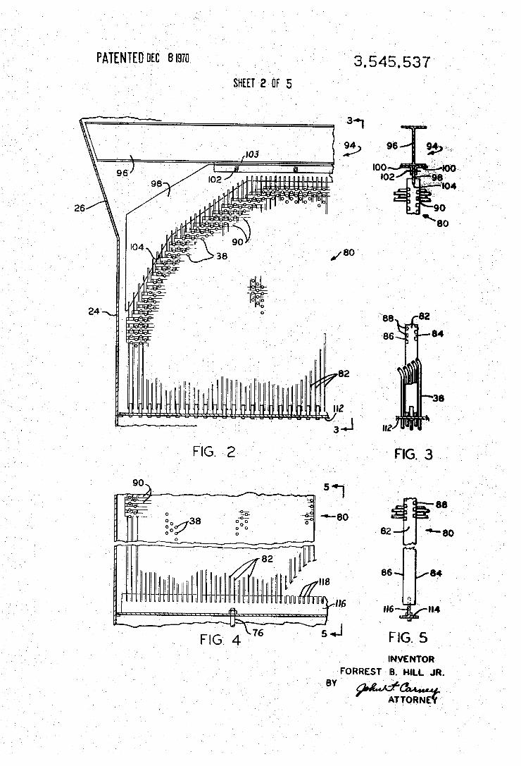
FIG. 1 is a side elevation of a shell and tube type vapor generator having a tube bundle incorporating the tube support structure of the present invention; FIG.2 is a partial elevational section taken along line 2-2 of
FIG.1; FIG.3 is a partial elevational section taken along line 3–3 of
FIG. 2; FIG. 4 is a partial elevational section taken along line 4-4 of
FIG. 1; . . . . -
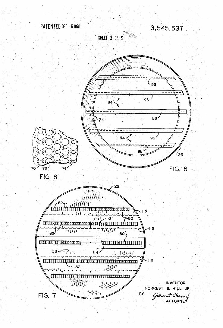
FIG.5 is a partial elevational section taken along line 5-5 of FIG. 4; FIG. 6 is a plansection taken along line 6-6 of FIG. 1; FIG.7 is a plansection taken along line 7-7 of FIG.1; FIG. 8 is a partial plan section taken along line 8-8 of FIG.
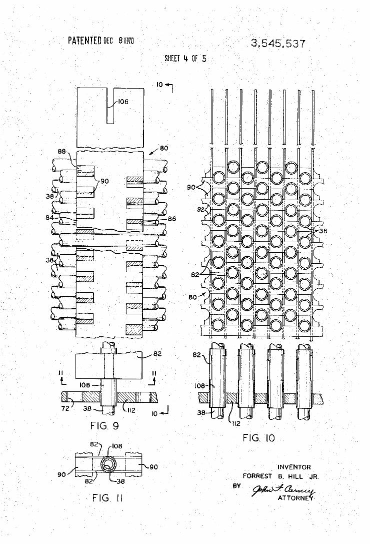
FIG.9 is a partial elevational view of the tube support struc ture of the present invention;
FIG. 10 is a partial elevational view taken along line 10-10 of FIG.9;
FIG. 11 is a plan section taken along line 11-11 of FIG. 9; and
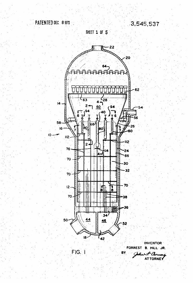
FIG. 12 is a partial isometric representation of the tube sup port structure of FIG.9. DESCRIPTION OF THE PREFERREDEMBODIMENT In FIG. 1 of the drawings, there is shown a shell and tube
type vapor generator 10 incorporating the present invention. The vapor generator 10 comprises a vertically elongated pres sure vessel defined by a lower cylindrical shell 12 and a larger diameter, upper cylindrical shell 14 integrally connected with the lower shell by means of a frustoconical transition member 16. The ends of the vessel are closed, at the bottom by means of hemispherically formed closure head 18 and at the top by a dome-shaped cover 20 containing a vapor outlet nozzle 22. The interior of the pressure vessel contains baffle plate mem bers 24, 26, and 28 that cooperate with the nozzles of the shells to form an inner vessel generation chamber 30 and an outer, annular downcomer passage 32. At the lower end of the lower shell 12, and intermediate it and closure head 18, is disposed a tube sheet 34 that extends transversely of the cen terline of the vessel and connects with the wall of the shell. The tube sheet 34 contains a plurality of tube openings 36 adapted to fixedly receive the ends of U-shaped heat exchange tubes 38 that form a longitudinally extending tube bundle 40 substantially filling the lower region of the vapor generation chamber 30. The tube openings 36 extend through the tube sheet 34 to place the tubes 38 in fluid communication with a heating fluid chamber 42 that occupies that region of the ves sel enclosed between the closure head 18 and the tube sheet 34 and which is divided into inlet and outlet portions 44 and
disposed on alternate spacing and adapted to receive elon- 75.46, respectively, by means of a diametrical plate 48. The tubes

3,545,537 3
38 of the tube bundle 40 are arranged such that their opposite ends communicate with one of the respective portions of the chamber 42 for the throughflow of heating fluid through the tubes. The chamber 42 is connected to a source of heating fluid (not shown) by means of inlet and outlet nozzles 50 and 52, respectively, that communicate with the respective chamber portions 44 and 46 and thereby effect circulation of heating fluid through the tubes. Feedwater is supplied to the unit through an inlet nozzle 54 that is shown penetrating the upper shell 14. A ring header 56 connects with the nozzle 54 and serves to distribute feedwater passed through the nozzle about the circumference of the downcomer passage 32 discharging it into the passage by means of downwardly directed discharge ports 58 that are spacedly disposed about the lower surface of the header. Flow of the feedwater from the downcomer passage 32 into the vapor generation chamber 30 is effected by the spaced relationship that exists between the lower end of the baffle plate 24 and the upper surface of the tube sheet 34. Within the vapor generation chamber 30 the feedwater is
caused to flow in heat exchange relation with the tubes 38 where heat is extracted from the heating fluid circulated therethrough to cause some of the feedwater to be trans formed into vapor. The so-created vapor-liquid mixture flows to the upper region of the vapor generation chamber 30 which is formed as a mixture collection chamber 60 as defined by the cooperation between the baffle plates 26 and 28. From the mixture collection chamber 60 the flowing mixture is passed to vapor-liquid separator apparatus, a multiplicity of such separators indicated as 62 being mounted upon baffle plate 28 and communicating with the chamber 60 by means of openings 63 provided in the plate. The separators 62 may be of any well-known construction and are arranged to discharge separated liquid downwardly upon the baffle plate 28 from whence it is returned to the downcomer passage 32 to be mixed with the incoming feedwater and recirculated through the unit. The separated vapor, on the other hand, is discharged from the separators in the upward direction and passes through appropriate contact drying apparatus 64 from whence it is passed out the vapor outlet nozzle 22 to a point of use. As is common in vapor generators of the disclosed type, the U tubes that comprise the tube bundle 40 each include a pair of straight, vertically extending leg portions 66 interconnected by a horizontally extending connecting portion 68. In the tube bundle 40 of the unit disclosed herein, the great majority of the tubes 38 have connecting portions 68 that are generally straight. Those tubes, however, that lie in the innermost tube rows may be formed, as shown, with connecting portions that are generally arcuate in shape. All of the tubes 38 are small diameter, thin walled tubes that are arranged, as shown in FIG. 2, in closely spaced layers with each layer containing a plurality of parallel tubes. In order to provide maximum heat transfer effectiveness, the tube layers of the present arrange ment are disposed such that the tubes therein have their cen ters located on a triangular pitch. Such arrangement, as can be seen from FIG.10, places the tubes of each tube layer in align ment with spaces between the tubes of the adjacent layer, thereby to expose a greater amount of heating surface to the flowing vaporizable fluid.
Because the distance between the secured ends of the tubes 38 in the tube sheet 34 and the top of the tube bundle 40 is of considerable magnitude as compared with the diameter of the tubes, means must be provided for spacedly supporting the tubes in order to protect them against damage caused by flow induced and/or mechanically-induced vibration and also to impart sufficient rigidity to the tubes in order to maintain their natural spaced relationship in the tube bundle. In the disclosed arrangement, a plurality of axially spaced horizontally extend ing plates 70 are disposed throughout a substantial portion of the height of the tube bundle 40 and operate to spacedly sup port the straight leg portion 66 of tubes 38. These spacer plates. 70, being of well-known construction, have surfaces that, as shown in FIG. 8, contain a plurality of aligned
4 openings 72 through which the leg portions 66 of the tubes 38 are passed. A number of small diameter openings 74 are disposed about each of the tube openings 72 and serve to ef. fect longitudinal flow of vaporizable fluid through the planes of the plates. Vertical support for the plate 70 is provided by appropriate connector means that attach the plates at circum
10
15
25
30
ferentially spaced positions about their outer peripheral edges to the inner surface of the baffle plate 24. Additional support for these plates may be provided intermediate their span by at tachment to tie rod 76 that connect at their lower ends to the tube sheet 34 and which extend longitudinally of the vapor generation chamber 30 for the principal purpose of supporting tube support structure attachment plates 112 as described hereinafter. According to the present invention means are provided to
spacedly support the laterally extending connecting portion 68 of the U-tubes 38 in the upper region of the tube bundle 40. In the arrangement illustrated in FIG. 1 of the drawings, five laterally spaced tube support structures indicated as 80 and 80' and constructed according to the invention are disclosed. It should be understood, however, that a greater or less number of tube support structure can be employed in various tube bundle applications without departing from the scope of the present invention. W.
Separate designations have been accorded to the tube sup port structures 80 and 80' herein for the reason that, while the structures both embody essentially the same structural con figuration, as explained hereinafter, different means are em ployed to anchor the lower ends of the structure due to the particular region of the tube bundle within which each is located, the former being in a region wherein the anchor means are secured by tubes 38 and the latter being disposed in
35
40
a region that is void of tubes. The tube support structures 80 and 80' each comprise a plu
rality of vertically elongated, thin, flat plate members 82 that are spacedly disposed in front-to-rear alignment between ad jacent layers of tubes 38 in the upper region of the tube bundle 40. As shown in FIGS. 2 through 5, the plate members 82 that comprise the respective support structures 80 or 80' are caused to extend perpendicularly of the connecting portion 68 of the U-tubes 38 between upper and lower structural support members as hereinafter described. The plate members 82 (FIGS. 9 and 12) are each formed on their oppositely spaced
5 side edges 84 and 86 with vertically spaced, rectangular
50
55
60
65
recesses 88, the recesses on the respective edges, being al ternately spaced from those on the opposite edge. The disposi tion of the plate members 82 of each support structure 80 or 80' is such as to place corresponding recesses on the plate members in horizontal front-to-rear alignment thus to sup: portingly receive tube spacer bars 90. The spacer bars 90 are horizontally elongated members that extend through the tube bundle 40 between adjacent tubes and perpendicular of the axis of the connection portion 68 thereof. The upper and lower surfaces of the spacer bars 90 are provided with arcuate recesses 92 that conform with the exterior of the tube surface 38, thereby to supportingly engage the tubes and maintain them in mutually spaced relation. Because the tubes 38 of the tube bundle 40 in the described embodiment are arranged in a triangular pitch disposition, the recesses 92 on the opposed surfaces of spacer bars 90 are alternately spaced. Alternative ly, were the tubes to be arranged with a square pitch, the recesses 92 on the surfaces of the spacer bars would be disposed in oppositely spaced relation. As can be seen best from examination of FIG. 12, each o
the connecting portions 68 of U-tubes 38 as it passes through
70
75
the plane of the respective tube support structure 80 or 80' is supportingly spaced from vertically adjacent tubes by one spacerbar 90 on one side edge of the plate member 82 whose tube engaging recess 92 is disposed on the undersurface of the bar and by another bar 90 on the opposite side edge of the plate member whose tube engaging recess is disposed on the upper surface of the bar. By means of this arrangement, each tube is effectively engaged about its full circumference by the

3,545,537 S
tube support structure yet adequate lateral and vertical spac ing is provided between the tube support members to effectin sufficient impedance to longitudinal and crossflow of vaporizable fluid through this region of the tube bundle. , Each of the tube support structures 80 or 80' is suspendedly
mounted within the unit by means of mounting assemblies in dicated generally in the respective FIGS. as 94. These assem blies each consist of a horizontally disposed structural member such as I-beam 96, that extends across the width of the vapor generation chamber 30 in overlying relation to its associated tube support structure and having its opposite ends fixedly secured to the inner surface of the chamber defining plate, here shown as baffle plate 26, as by means of welding or otherwise. A suspension plate 98 is slideably secured to the underside of I-beam 96 by means of oppositely spaced angle members 100 whose depending legs form a guideway that receives the upper edge of the plate 98. Within the space defined by the angle members 100, a slight clearance is pro vided between the upper end of the suspension plate 98 and the lower flange of beam 96. Connection between the plate 98 and anchors 100 is effected by means of threaded connectors 102 that cooperate with slotted openings 103 in the plate. In this way any upward expansion of the tube bundle relative to the mounting assembly, as will occur when the unit is placed in operation, will be readily accommodated. Attachment of the tube support structures 80 and 80' to the
mounting assembly 94 is effected in the manner shown in FIGS. 2 and 3 wherein, in the disclosed arrangement, the suspension plate 98 is formed with the lower end edge 104 having the general configuration of the outline of the upper end of the tube bundle 40, and the upper ends of the tube sup port structure plate members 82 are fixedly secured at longitu dinally spaced points along the length of the edge, as by weld ing. To facilitate the connection of the plate members 82 to the suspension plate 98, the upper ends of the former are pro vided with a vertical slot 106 (FIG. 9) to receive the lower end of the latter. At their lower ends each of the plate members 82 is connected to horizontally disposed anchor means (at tachment plates 112 with respect to structures 80 and anchor beam 114 with respect to structures 80') to preserve the spaced relation between the members at the bottom of the respective structures. The connections between the plate and anchor members are, however, such as will permit vertical movement of the tube support structure in response to relative thermal expansion between the tubes 38 and the mounting as sembly 94. The connection between the plate members 82 and attachment plate 112 is effected in the tube support structure indicated as 80 in the manner shown in FGS. 2, 3,9, and 10. With reference to the latter FIGS., it can be seen that the ver tical plate members 82 are arranged in pairs and the lower ends of the plates of each pair are weldedly secured in op positely spaced relation to the outer surface of a short, hollow, cylindrical sleeve 108, Sleeve 108 is formed with an inside diameter that enables it to be telescopically disposed over an adjacent tube 38 and an outside diameter that permits it to be slideably received in an opening 110 provided in its associated attachment plates 112. The attachment plates 112 are horizontally disposed plates located in the region of the tube bundle 40 immediately below the U-tube bend and have a peripheral configuration of chordal sections of a circle (FIG. 7). Vertical support for the respective plates 112 is provided by appropriate attachment means that secure the plates to the inner surface of baffle plate 26 and by tie rods 76 that connect with the plates at spaced points adjacent their chordal edge. The surface of the plates 112 is similar to that of the tube sup port plate 70 having a multiplicity of aligned tube openings 72 that permit passage of the leg portions 60 of tubes 38 and smaller diameter openings 74 thereabout to permit longitu dinal flow of vaporizable fluid through the plates. They differ, however, in that the aligned openings 110 that underlie the tube support structures 80 are oversized holes to slidingly receive the structures 108 and their enclosed tubes 38.
6 Connection of the lower end of the tube support structure
indicated as 80" differs from that of the tube support structure 80. As shown in FIG. 2, the bottom of the structure 80' is located in a region of the tube bundle 40 that is void of tubes
5 38. An inverted T-shaped anchor beam 114 extends through the tube bundle having its opposite ends secured by ap propriate attaching means to the inner surface of the downcomer baffle plate 24. The beam 114 may be supported at longitudinally spaced points intermediate its ends by tie rod
976. The upstanding leg 116 of the beam 114 is provided along the length of its upper end edge with slots 118 adapted to slidingly receive the lower ends of the tube support plate members 82, the latter having the same general configuration of the tube support plate members employed instructures 80, but being provided at their lower end with slotted edges that are slideably received in the T-beam slots 118. By means of the novel tube support structure of the present
invention, there is provided a simple, inexpensive apparatus operative to spacingly support the laterally extending portions of each of the U-tubes that occupy the upper region of a tube bundle employed in a vapor generator of the shell and tube type against the damaging effects of flow-induced and/or mechanically-induced vibration. Relative vertical movement between the tubes is prevented by the opposed disposition of the tube support bars between each vertically spaced tube portion while relative lateral movement between adjacent tubes is prevented by both the interposed vertical plate mem bers and the tube engaging recesses in the support bars. Ther mally-induced relative movement between the tubes and the shell enclosure is accommodated by the "floating' connection provided between the tube support structures and their as sociated supports. And finally, both heat transfer effectiveness and fluid flow efficiency are maintained at a high degree due to the presence of sufficient flow area through the the tube support structure due to the linear displacement existing between the members of the structure.
It will be understood that various changes in the details, materials, and arrangements of parts which have been herein described and illustrated in order to explain the nature of the invention may be made by those skilled in the art within the principle and scope of the invention as expressed in the ap pended claims.
I claim: 1. In combination, a shell and tube heat exhanger compris
ing: a. a substantially closed vessel; b. abundle of inverted U-tubes enclosed by said vessel, said
50 tubes being disposed in spaced layers of aligned mutually spaced tubes;
c. tube sheet means disposed at one end of said vessel for at taching the ends of said tubes;
d. tube support structure for suspendedly supporting the bend portion of the tubes in mutually spaced relation in cluding: -
i. vertically elongated plate members having laterally spaced side edges disposed between each of said tube layers, said plate members being alignedly arranged along a plane intersecting the planes of said tube layers,
ii. a row of mutually spaced, horizontally elongated spacer bars arranged along each side edge of said plate members and extending parallel to the plane of the as sembled plate members in interposed relation between the connecting portions of adjacent tubes in said tube layers,
iii. means for attaching said spacer bars to said plate members; and
e. means for connecting said plate members in relation to said vessel including: i. structural means disposed above said tube bundle and
extending tranversely of said vessel in parallel, overly ing relation to said tube support structure,
ii. means for attaching the opposed ends of said structural members in fixed relation to said vessel,
15
25
30
35
40
45
55
60
65
70
75

3,545,537 iii. a structure, elongated suspension plate substantially
collateral with said tube support structure, iv. means for attaching the upper ends of said plate mem
bers to said suspension plate, and v. means for expansably connecting said suspension plate to said structural means.
2. Apparatus as recited in claim 1 wherein said tube support structure includes spacer bars in each row having surfaces for engaging the bend portions of the tubes of each layer on cor responding sides thereof and the bars of the respective rows engaging the tubes on opposite sides thereof.
3. Apparatus as recited in claim 1 including means for securing the lower ends of said plate members in spaced rela tion, said means comprising: a.attachment plate means fixedly secured with respect to
said baffle plate means and extending transversely of said vapor generation chamber in intersecting relation to the leg portions of the tubes of said tube bundle;
b. means forming first openings in said attachment plate means for passage of the leg portions of said tubes;
c. means forming second openings disposed in said at
5
10
15
20
25
30
35
40
45
50
55
60
65
70
75
8 tachment plate means in underlying relation to said tube support structure;
d. a plurality of sleeves positioned in said second openings in longitudinal slideable relation therewith, said sleeves: being disposed between the lower ends of alternate plate members of said tube support structure; and
e. means for fixedly securing each of said sleeves to thead jacent pair of plate members.
4. Apparatus as recited in claim 3 wherein said sleeves are hollow, cylindrical members and each concentrically encloses the leg portion of an associated tube of said tube bundle.
5. Apparatus as recited in claim 1 including means for securing the lower ends of said plate members in spaced rela tion, said means comprising: a means forming an attachment beam extending transverse
ly of said vapor generation chamber in underlying, paral lel relation to said tube support structure; and
b. means forming longitudinally spaced slots in said beam for slideably receiving the lower ends of said plate mem bers.


![Modal analysis of a thin cylindrical shell with top mass · thin cylindrical shell with top mass [1]. This traineeship is part of the research project of N.J. Mallon. During this](https://img.dokumen.tips/doc/110x75/5e8dcf331b84e55f7c72b05f/modal-analysis-of-a-thin-cylindrical-shell-with-top-mass-thin-cylindrical-shell.jpg)