Embed Size (px)
Citation preview
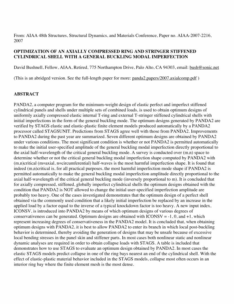
From: AIAA 48th Structures, Structural Dynamics, and Materials Conference, Paper no. AIAA-2007-2216, 2007 OPTIMIZATION OF AN AXIALLY COMPRESSED RING AND STRINGER STIFFENED CYLINDRICAL SHELL WITH A GENERAL BUCKLING MODAL IMPERFECTION David Bushnell, Fellow, AIAA, Retired, 775 Northampton Drive, Palo Alto, CA 94303, email: [email protected] (This is an abridged version. See the full-length paper for more: panda2.papers/2007.axialcomp.pdf ) ABSTRACT PANDA2, a computer program for the minimum-weight design of elastic perfect and imperfect stiffened cylindrical panels and shells under multiple sets of combined loads, is used to obtain optimum designs of uniformly axially compressed elastic internal T-ring and external T-stringer stiffened cylindrical shells with initial imperfections in the form of the general buckling mode. The optimum designs generated by PANDA2 are verified by STAGS elastic and elastic-plastic finite element models produced automatically by a PANDA2 processor called STAGSUNIT. Predictions from STAGS agree well with those from PANDA2. Improvements to PANDA2 during the past year are summarized. Seven different optimum designs are obtained by PANDA2 under various conditions. The most significant condition is whether or not PANDA2 is permitted automatically to make the initial user-specified amplitude of the general buckling modal imperfection directly proportional to the axial half-wavelength of the critical general buckling mode. A survey is conducted over (m,n) space to determine whether or not the critical general buckling modal imperfection shape computed by PANDA2 with (m,n)critical (m=axial, n=circumferential) half-waves is the most harmful imperfection shape. It is found that indeed (m,n)critical is, for all practical purposes, the most harmful imperfection mode shape if PANDA2 is permitted automatically to make the general buckling modal imperfection amplitude directly proportional to the axial half-wavelength of the critical general buckling mode (inversely proportional to m). It is concluded that for axially compressed, stiffened, globally imperfect cylindrical shells the optimum designs obtained with the condition that PANDA2 is NOT allowed to change the initial user-specified imperfection amplitude are probably too heavy. One of the cases investigated demonstrates that the optimum design of a perfect shell obtained via the commonly used condition that a likely initial imperfection be replaced by an increase in the applied load by a factor equal to the inverse of a typical knockdown factor is too heavy. A new input index, ICONSV, is introduced into PANDA2 by means of which optimum designs of various degrees of conservativeness can be generated. Optimum designs are obtained with ICONSV = -1, 0, and +1, which represent increasing degrees of conservativeness in the PANDA2 model. It is concluded that, when obtaining optimum designs with PANDA2, it is best to allow PANDA2 to enter its branch in which local post-buckling behavior is determined, thereby avoiding the generation of designs that may be unsafe because of excessive local bending stresses in the panel skin and stiffener parts. In most cases both nonlinear static and nonlinear dynamic analyses are required in order to obtain collapse loads with STAGS. A table is included that demonstrates how to use STAGS to evaluate an optimum design obtained by PANDA2. In most cases the elastic STAGS models predict collapse in one of the ring bays nearest an end of the cylindrical shell. With the effect of elastic-plastic material behavior included in the STAGS models, collapse most often occurs in an interior ring bay where the finite element mesh is the most dense.
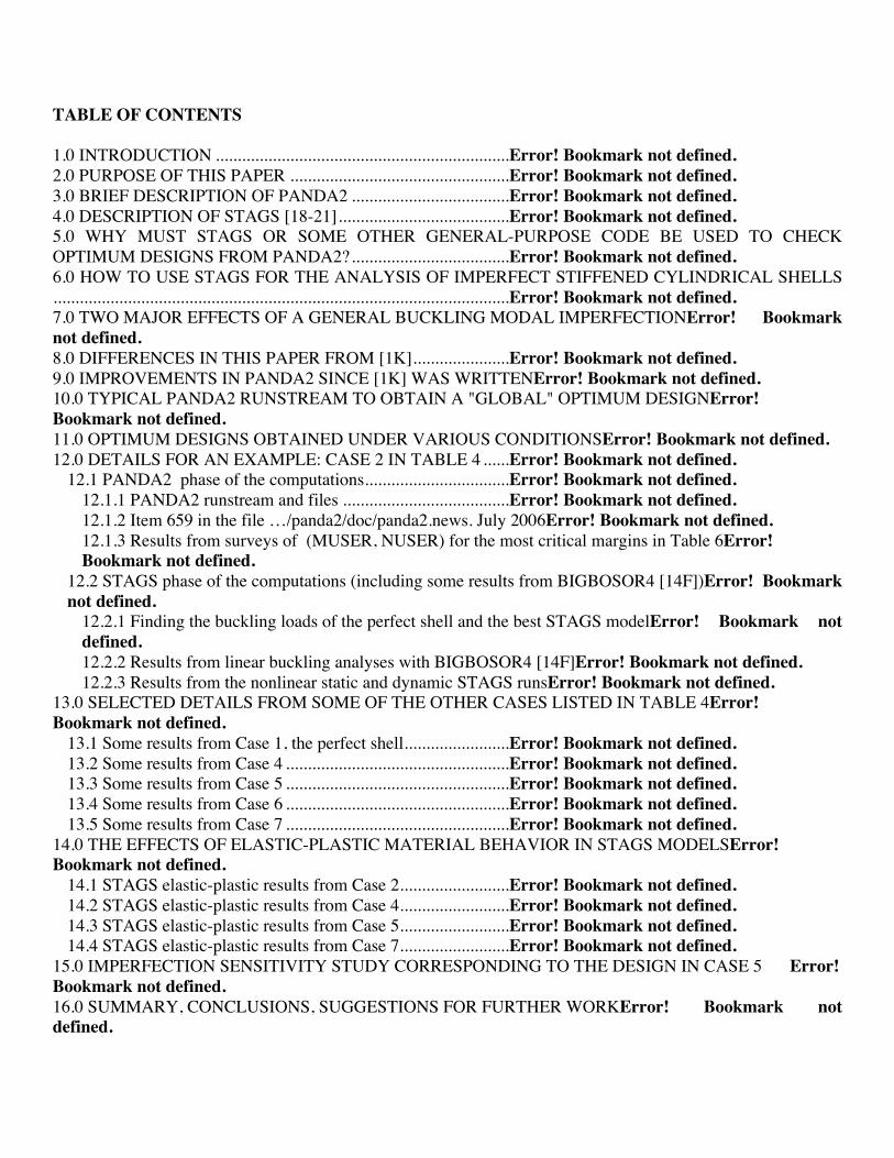
TABLE OF CONTENTS 1.0 INTRODUCTION ...................................................................Error! Bookmark not defined. 2.0 PURPOSE OF THIS PAPER ..................................................Error! Bookmark not defined. 3.0 BRIEF DESCRIPTION OF PANDA2 ....................................Error! Bookmark not defined. 4.0 DESCRIPTION OF STAGS [18-21].......................................Error! Bookmark not defined. 5.0 WHY MUST STAGS OR SOME OTHER GENERAL-PURPOSE CODE BE USED TO CHECK OPTIMUM DESIGNS FROM PANDA2?....................................Error! Bookmark not defined. 6.0 HOW TO USE STAGS FOR THE ANALYSIS OF IMPERFECT STIFFENED CYLINDRICAL SHELLS........................................................................................................Error! Bookmark not defined. 7.0 TWO MAJOR EFFECTS OF A GENERAL BUCKLING MODAL IMPERFECTIONError! Bookmark not defined. 8.0 DIFFERENCES IN THIS PAPER FROM [1K]......................Error! Bookmark not defined. 9.0 IMPROVEMENTS IN PANDA2 SINCE [1K] WAS WRITTENError! Bookmark not defined. 10.0 TYPICAL PANDA2 RUNSTREAM TO OBTAIN A "GLOBAL" OPTIMUM DESIGNError! Bookmark not defined. 11.0 OPTIMUM DESIGNS OBTAINED UNDER VARIOUS CONDITIONSError! Bookmark not defined. 12.0 DETAILS FOR AN EXAMPLE: CASE 2 IN TABLE 4 ......Error! Bookmark not defined.
12.1 PANDA2 phase of the computations.................................Error! Bookmark not defined. 12.1.1 PANDA2 runstream and files ......................................Error! Bookmark not defined. 12.1.2 Item 659 in the file …/panda2/doc/panda2.news. July 2006Error! Bookmark not defined. 12.1.3 Results from surveys of (MUSER, NUSER) for the most critical margins in Table 6Error! Bookmark not defined.
12.2 STAGS phase of the computations (including some results from BIGBOSOR4 [14F])Error! Bookmark not defined.
12.2.1 Finding the buckling loads of the perfect shell and the best STAGS modelError! Bookmark not defined. 12.2.2 Results from linear buckling analyses with BIGBOSOR4 [14F]Error! Bookmark not defined. 12.2.3 Results from the nonlinear static and dynamic STAGS runsError! Bookmark not defined.
13.0 SELECTED DETAILS FROM SOME OF THE OTHER CASES LISTED IN TABLE 4Error! Bookmark not defined.
13.1 Some results from Case 1, the perfect shell........................Error! Bookmark not defined. 13.2 Some results from Case 4 ...................................................Error! Bookmark not defined. 13.3 Some results from Case 5 ...................................................Error! Bookmark not defined. 13.4 Some results from Case 6 ...................................................Error! Bookmark not defined. 13.5 Some results from Case 7 ...................................................Error! Bookmark not defined.
14.0 THE EFFECTS OF ELASTIC-PLASTIC MATERIAL BEHAVIOR IN STAGS MODELSError! Bookmark not defined.
14.1 STAGS elastic-plastic results from Case 2.........................Error! Bookmark not defined. 14.2 STAGS elastic-plastic results from Case 4.........................Error! Bookmark not defined. 14.3 STAGS elastic-plastic results from Case 5.........................Error! Bookmark not defined. 14.4 STAGS elastic-plastic results from Case 7.........................Error! Bookmark not defined.
15.0 IMPERFECTION SENSITIVITY STUDY CORRESPONDING TO THE DESIGN IN CASE 5 Error! Bookmark not defined. 16.0 SUMMARY, CONCLUSIONS, SUGGESTIONS FOR FURTHER WORKError! Bookmark not defined.
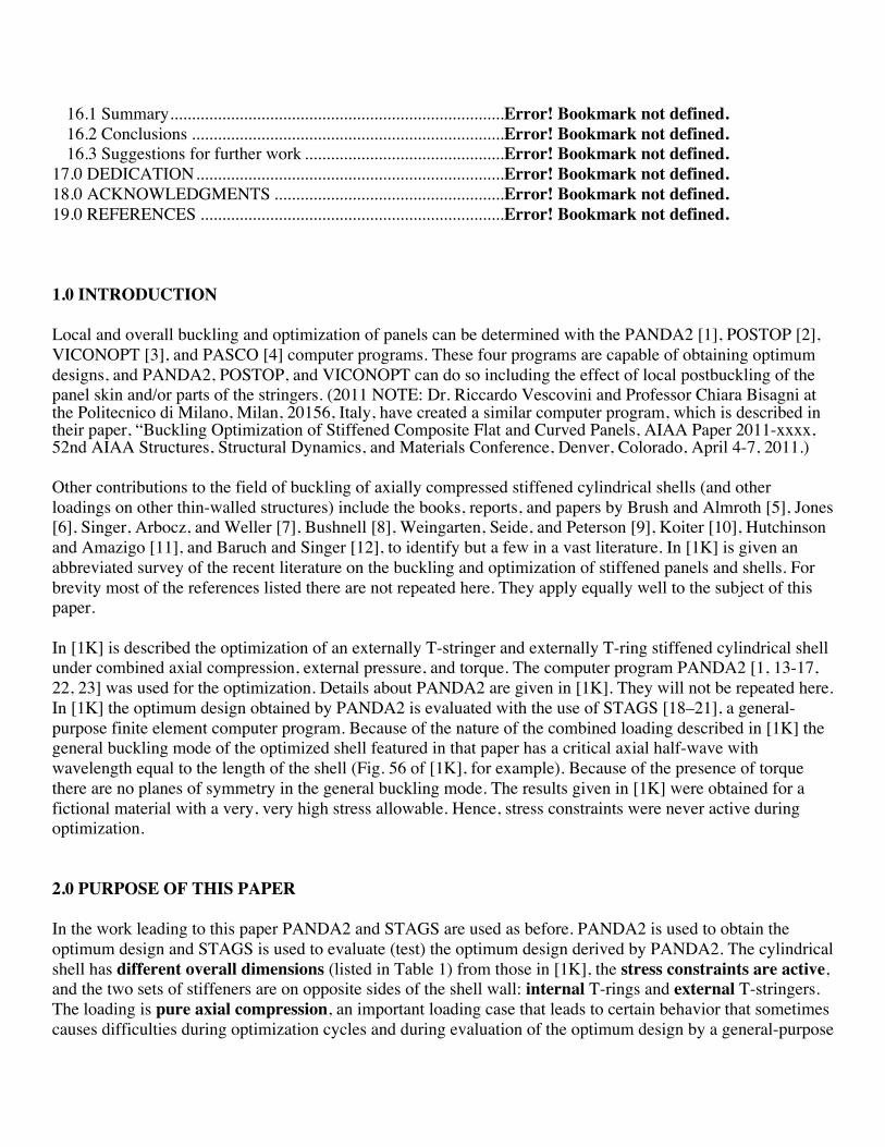
16.1 Summary.............................................................................Error! Bookmark not defined. 16.2 Conclusions ........................................................................Error! Bookmark not defined. 16.3 Suggestions for further work ..............................................Error! Bookmark not defined.
17.0 DEDICATION.......................................................................Error! Bookmark not defined. 18.0 ACKNOWLEDGMENTS .....................................................Error! Bookmark not defined. 19.0 REFERENCES ......................................................................Error! Bookmark not defined. 1.0 INTRODUCTION Local and overall buckling and optimization of panels can be determined with the PANDA2 [1], POSTOP [2], VICONOPT [3], and PASCO [4] computer programs. These four programs are capable of obtaining optimum designs, and PANDA2, POSTOP, and VICONOPT can do so including the effect of local postbuckling of the panel skin and/or parts of the stringers. (2011 NOTE: Dr. Riccardo Vescovini and Professor Chiara Bisagni at the Politecnico di Milano, Milan, 20156, Italy, have created a similar computer program, which is described in their paper, “Buckling Optimization of Stiffened Composite Flat and Curved Panels, AIAA Paper 2011-xxxx, 52nd AIAA Structures, Structural Dynamics, and Materials Conference, Denver, Colorado, April 4-7, 2011.) Other contributions to the field of buckling of axially compressed stiffened cylindrical shells (and other loadings on other thin-walled structures) include the books, reports, and papers by Brush and Almroth [5], Jones [6], Singer, Arbocz, and Weller [7], Bushnell [8], Weingarten, Seide, and Peterson [9], Koiter [10], Hutchinson and Amazigo [11], and Baruch and Singer [12], to identify but a few in a vast literature. In [1K] is given an abbreviated survey of the recent literature on the buckling and optimization of stiffened panels and shells. For brevity most of the references listed there are not repeated here. They apply equally well to the subject of this paper. In [1K] is described the optimization of an externally T-stringer and externally T-ring stiffened cylindrical shell under combined axial compression, external pressure, and torque. The computer program PANDA2 [1, 13-17, 22, 23] was used for the optimization. Details about PANDA2 are given in [1K]. They will not be repeated here. In [1K] the optimum design obtained by PANDA2 is evaluated with the use of STAGS [18–21], a general-purpose finite element computer program. Because of the nature of the combined loading described in [1K] the general buckling mode of the optimized shell featured in that paper has a critical axial half-wave with wavelength equal to the length of the shell (Fig. 56 of [1K], for example). Because of the presence of torque there are no planes of symmetry in the general buckling mode. The results given in [1K] were obtained for a fictional material with a very, very high stress allowable. Hence, stress constraints were never active during optimization. 2.0 PURPOSE OF THIS PAPER In the work leading to this paper PANDA2 and STAGS are used as before. PANDA2 is used to obtain the optimum design and STAGS is used to evaluate (test) the optimum design derived by PANDA2. The cylindrical shell has different overall dimensions (listed in Table 1) from those in [1K], the stress constraints are active, and the two sets of stiffeners are on opposite sides of the shell wall: internal T-rings and external T-stringers. The loading is pure axial compression, an important loading case that leads to certain behavior that sometimes causes difficulties during optimization cycles and during evaluation of the optimum design by a general-purpose

computer code such as STAGS. These difficulties arise mainly because the critical buckling mode of the optimized shell usually has several axial half-waves rather than just one axial half-wave, as was the case in the study described in [1K]. Figures 1a,b,c and 2 show the configuration treated in this paper, a typical general buckling mode (Fig. 1), and the cylindrical shell with a general buckling modal imperfection as deformed under the design load (Fig. 2). Because of the absence of in-plane shear loading (torque) and the absence of anisotropy in the cases explored here, there are multiple planes of symmetry in the general buckling mode of the perfect shell and hence in the imperfect shell with a general buckling modal imperfection shape derived from a linear bifurcation buckling analysis of the perfect shell. See Fig. 1b, for example. Therefore, STAGS models of the imperfect shell that include much less than 360 degrees of circumference are valid provided the symmetry planes at the two straight edges (generators) bound a circumferential sector that permits an integral number of circumferential half-waves with circumferential wavelength equal to that of the critical general buckling mode of the perfect, complete optimized cylindrical shell. For reasons described below, in most of the cases examined here the most refined models span a circumferential arc of one full circumferential wave of the critical general buckling mode, not just one half circumferential wave. It is emphasized that in this paper the stress constraints are active. They therefore influence the evolution of the design during optimization cycles. The shell material is aluminum with an allowable effective (von Mises) stress of 60 ksi. In all the PANDA2 runs the material remains elastic. PANDA2 cannot handle elastic-plastic material behavior. Most STAGS runs are with elastic models. Some STAGS models are processed in which elastic-plastic material behavior is accounted for (Figs. 81-95). Figure 2 displays a typical distribution of effective (von Mises) stress in a STAGS model of an elastic imperfect cylindrical shell previously optimized by PANDA2 and subjected to the design load, axial compression Nx = -3000 lb/in. Improvements to PANDA2 implemented since [1K] was written are briefly described in Section 9. In this paper several optimum designs are obtained for the same system: an elastic, imperfect, uniformly axially compressed, internal T-ring and external T-stringer stiffened, simply-supported aluminum cylindrical shell 75 inches long and 50 inches in diameter (Tables 1 and 2 and Figs. 1 and 2). Optimum designs are obtained with respect to three types of model choice: 1. Model choice type 1: Optimum designs are obtained for three values of a “conservativeness index”, ICONSV = –1, 0, and 1, which governs how conservative the PANDA2 model is (Item 676 in Section 9.0): a. with respect to knockdown factors to compensate for the inherent unconservativeness of smearing stringers and smearing rings, b. with respect to a knockdown factor for imperfection sensitivity computed from equations given by Arbocz in [1D], and c. with respect to a knockdown factor to compensate for truncation error in the double trigonometric series expansion of the alternative solution for general buckling [1G].

2. Model choice type 2: Optimum designs are obtained for two strategies with respect to the modeling of a general buckling modal imperfection [1K]: a. Strategy 1: the initial user-specified amplitude, Wimp, of the imperfection in the shape of the critical (lowest eigenvalue) general buckling mode of the perfect shell remains fixed during optimization cycles, and b. Strategy 2: the initial user-specified amplitude, Wimp, of the critical general buckling modal imperfection is changed during optimization cycles such that Wimp becomes proportional to the axial wavelength of the critical general buckling mode. This strategy is based on the assumption that general buckling modal imperfections with many axial waves are more detrimental that those with fewer axial waves, given the amplitude, Wimp. Imperfections with short axial wavelengths are probably easier to detect than those with long axial wavelengths, given the amplitude, Wimp. Therefore, fabricated shells with short-wavelength imperfections would more likely be discarded or repaired than fabricated shells with long-wavelength imperfections, given the amplitude, Wimp. 3. Model choice type 3: Optimum designs are obtained for two models of local postbuckling [1C]: a. Local postbuckling IS allowed to occur, and b. Local postbuckling is NOT allowed to occur. Not all combinations of these three types of model choices are explored, just enough to learn what the effect of one type of model choice is while the other two types of model choice remain the same. Many examples are provided to give the reader a “feel” for the behavior of axially compressed, stiffened, imperfect cylindrical shells. Predictions of the behavior of shells optimized by PANDA2 are validated by STAGS [18-21] and BOSOR4 [14] (2011 NOTE: now superseded by BIGBOSOR4) models. 3.0 BRIEF DESCRIPTION OF PANDA2 See [1A] and [1K] for more details. PANDA2 is a computer program for the minimum weight design of elastic, ring and stringer stiffened, composite, flat or cylindrical, perfect or imperfect panels and cylindrical shells subjected to multiple sets of combined in-plane loads, normal pressure, edge moments, and temperature. For most configurations the panels can be locally postbuckled [1C]. Previous work on PANDA2 is documented in [1A-L, 22, 23]. PANDA2 incorporates the theories of earlier codes PANDA [1B,13] and BOSOR4 (called “BIGBOSOR4” in this paper) [14]. The local postbuckling analysis [1C] is based on a model by Koiter [15] (different from Koiter’s “classical” asymptotic imperfection sensitivity theory in [10]). The optimizer used in PANDA2 is called ADS [16,17]. Panels are optimized subject to buckling and stress constraints and certain inequality constraints (Table 1). Details about PANDA2 are given in the recent references listed under [1] (see especially [1K]). Therefore, these details will not be repeated here. Only the most significant improvements in PANDA2 since the publication of [1K] are briefly enumerated in Section 9 of this paper. 4.0 DESCRIPTION OF STAGS [18-21]
In most of the PANDA2 references listed under [1] and in [22, 23] and in this paper optimum designs obtained by PANDA2 are evaluated later via STAGS models. STAGS (STructural Analysis of General Shells [18–21]) is a finite element code for general-purpose nonlinear analysis of stiffened shell structures of arbitrary shape and complexity. Its capabilities include stress, stability, vibration, and transient analyses with both material and geometric nonlinearities permitted in all analysis types. STAGS includes enhancements, such as a higher order thick shell element, more advanced nonlinear solution strategies, and more comprehensive post-processing features such as a link with STAPL, a postprocessor used to generate many of the figures in this paper: figures that display the STAGS model, such as Figs. 1a-c and 2, for example. Research and development of STAGS by Rankin, Brogan, Almroth, Stanley, Cabiness, Stehlin and others of the Computational Mechanics Department of the Lockheed Martin Advanced Technology Center has been under continuous sponsorship from U.S. government agencies for the past 40 years. During this time particular emphasis has been placed on improvement of the capability to solve difficult nonlinear problems such as the prediction of the behavior of axially compressed stiffened panels loaded far into their locally postbuckled states. STAGS has been extensively used worldwide for the evaluation of stiffened panels and shells loaded well into their locally postbuckled states. See [21], for example. A large rotation algorithm that is independent of the finite element library has been incorporated into STAGS [20B]. With this algorithm there is no artificial stiffening due to large rotations. The finite elements in the STAGS library do not store energy under arbitrary rigid-body motion, and the first and second variations of the strain energy are consistent. These properties lead to quadratic convergence during Newton iterations. Solution control in nonlinear problems includes specification of load levels or use of the advanced Riks-Crisfield path parameter [21] that enables traversal of limit points into the post-buckling regime. Two load systems with different histories (Load Sets A and B) can be defined and controlled separately during the solution process. Flexible restart procedures permit switching from one strategy to another during an analysis, including shifts from bifurcation buckling to nonlinear collapse analyses and back and shifts from static to transient and transient to static analyses with modified boundary conditions and loading. STAGS provides solutions to the generalized eigenvalue problem for buckling and vibration from a linear (Fig. 24) or nonlinear (Figs. 26, 27) stress state. Quadric surfaces can be modeled with minimal user input as individual substructures called "shell units" in which the analytic geometry is represented exactly. "Shell units" can be connected along edges or internal grid lines with partial or complete compatibility. In this way complex structures can be assembled from relatively simple units. Alternatively, a structure of arbitrary shape can be modeled with use of an "element unit". Geometric imperfections can be generated automatically in a variety of ways, thereby permitting imperfection- sensitivity studies to be performed. For example, imperfections can be generated by superposition of several buckling modes determined from previous linear and nonlinear STAGS analyses of a given case. (See Parts 4- 7 of Table 9 and Figs. 24, 26, and 27, for example). A variety of material models is available, including both plasticity and creep. STAGS handles isotropic and anisotropic materials, including composites consisting of up to 60 layers of arbitrary orientation. Four plasticity models are available, including isotropic strain hardening, the White Besseling (mechanical sublayer model),
kinematic strain hardening, and deformation theory. Two independent load sets, each composed from simple parts that may be specified with minimal input, define a spatial variation of loading. Any number of point loads, prescribed displacements, line loads, surface tractions, thermal loads, and "live" pressure (hydrostatic pressure which remains normal to the shell surface throughout large deformations) can be combined to make a load set. For transient analysis the user may select from a menu of loading histories, or a general temporal variation may be specified in a user-written subroutine. Boundary conditions (B.C.) may be imposed either by reference to certain standard conditions or by the use of single- and multi-point constraints. Simple support, symmetry, anti-symmetry, clamped, or user-specified B.C. can be defined on a "shell unit" edge. Single-point constraints that allow individual freedoms to be free, fixed, or a prescribed non-zero value may be applied to grid lines and surfaces in "shell units" or "element units". A useful feature for buckling analysis allows these constraints to differ for the prestress and eigenvalue analyses. Langrangian constraint equations containing up to 100 terms may be defined to impose multi-point constraints. STAGS has a variety of finite elements suitable for the analysis of stiffened plates and shells. Simple four node quadrilateral plate elements with a cubic lateral displacement field (called "410" and "411" elements) are effective and efficient for the prediction of postbuckling thin shell response. A linear (410) or quadratic (411) membrane interpolation can be selected. For thicker shells in which transverse shear deformation is important (and for the thin-shell cases described in this paper), STAGS provides the Assumed Natural Strain (ANS) nine node element (called "480" element). A two node beam element compatible with the four node quadrilateral plate element is provided to simulate stiffeners and beam assemblies. Other finite elements included in STAGS are described in the STAGS literature [18-21]. 5.0 WHY MUST STAGS OR SOME OTHER GENERAL-PURPOSE CODE BE USED TO CHECK OPTIMUM DESIGNS FROM PANDA2? PANDA2 uses many approximations and “tricks” in models for stress and buckling. Some of these are described in Sections 8 - 10 of [1K]. For example, knockdown factors are derived to compensate for the inherent unconservativeness of smearing stiffeners [1K] and to account for the effects of transverse shear deformation [1A]. The effect of initial local, inter-ring, and general imperfections in the shapes of critical local, inter-ring, and general buckling modes are accounted for in an approximate manner as described in [1D] and [1E]. The distribution of prebuckling stress resultants in the various segments of a discretized skin-stringer module [1A and Fig. 4 in this paper] and of a “skin”-ring discretized module [1G] of an imperfect and therefore initially bent stiffened shell are approximate. For example, stabilizing (tensile) axial and hoop resultants in the panel skin that arise from prebuckling bending of an initially globally imperfect shell are neglected in order to avoid the production of unconservative optimum designs. PANDA2 has been developed over the years with the philosophy that the use of many relatively simple approximate models will lead to optimum designs that are reasonable and for which no complicated “combined” modes of failure will inadvertently be missed. Because of the approximate nature of these multiple simple PANDA2 models, one MUST use STAGS or some other general-purpose finite element code to evaluate optimum designs obtained by PANDA2. The particular advantage of using STAGS is that there exists a PANDA2 processor called STAGSUNIT [1I]
that automatically generates input files, *.bin and *.inp, for STAGS. As described in [1I], the processor STAGSUNIT is written in such a way that "patches" (sub-domains) of various portions of a complete panel or shell can be analyzed with STAGS. The correct prebuckled state of a perfect panel is preserved independently of the size of the "patch" to be included in the STAGS sub-domain model. The minimum size "patch" must contain at least one stiffener spacing in each coordinate direction. In a stringer-stiffened shell stringers are always included along the two straight edges of the "patch". There may or may not be rings running along the two curved edges of the "patch", depending on input to STAGSUNIT provided by the user of PANDA2. Stiffeners that run along the four boundaries of the "patch" have half the stiffness and half the loading of those that lie within the "patch". It is primarily this characteristic of the STAGS models produced by STAGSUNIT that preserves the correct prebuckled state of the “patch” independently of its size. The STAGS models are constructed by the PANDA2 processor, STAGSUNIT, in such a way that all stiffeners are connected only to the panel skin. That is, where stiffeners intersect they simply pass through one another with no constraints between them along their lines of intersection, if any. This is a conservative model with respect to buckling. The same model is used in PANDA2. The STAGSUNIT processor can generate models in which all stiffeners may be composed of shell units, one or more sets of stiffeners may be composed of beams, or one or more sets of stiffeners may be “smeared” as prescribed by Baruch and Singer [12]. 6.0 HOW TO USE STAGS FOR THE ANALYSIS OF IMPERFECT STIFFENED CYLINDRICAL SHELLS In order to use STAGS to evaluate a shell with a general buckling modal imperfection, one must: (see the paper). 7.0 TWO MAJOR EFFECTS OF A GENERAL BUCKLING MODAL IMPERFECTION Much of the following appears in Section 11.1 on p. 19 of [1K]. It is repeated here because this section is especially important. It briefly describes the behavior of a stiffened cylindrical shell with a general buckling modal imperfection shape. This behavior plays a major role in the evolution of the design during optimization cycles in PANDA2. Here it is assumed that the shortest wavelength of the general buckling modal imperfection is greater than the greatest stiffener spacing, as holds in Figs. 1 and 2, for example (disregarding the component of stringer bending-torsional deformation displayed in the expanded insert in Fig. 1a). A general buckling modal imperfection in a stiffened shell has two major effects: 1. The imperfect stiffened panel or shell bends as soon as any loading is applied. This prebuckling bending causes significant redistribution of stresses between the panel skin and the various stiffener parts, thus affecting significantly many local and inter-ring buckling and stress constraints (margins). 2. The "effective" circumferential curvature of an imperfect cylindrical panel or shell depends on the amplitude of the initial imperfection, on the circumferential wavelength of the critical buckling mode of the perfect and of the imperfect shell, and on the amount that the initial imperfection grows as the loading increases from zero to the design load. The "effective" circumferential radius of curvature of the imperfect and loaded cylindrical shell is larger than its nominal radius of curvature because the larger "effective" radius
corresponds to the maximum local radius of the cylindrical shell with a typical inward circumferential lobe of the initial and subsequently load- amplified buckling modal imperfection. In PANDA2 this larger local "effective" radius of curvature is assumed to be the governing UNIFORM radius in the buckling equations pertaining to the imperfect shell. For the purpose of computing the general buckling load, the imperfect shell is replaced by a new perfect cylindrical shell with the larger “effective” circumferential radius. By means of this device a complicated nonlinear collapse analysis is converted into a simple approximate bifurcation buckling problem - a linear eigenvalue problem. For each type of buckling modal imperfection (general, inter-ring, local [1E]) PANDA2 computes a "knockdown" factor based on the ratio: (buckling load factor: panel with its "effective" circumferential radius)/ (buckling load factor: panel with its nominal circumferential radius) Figures 1a,b,c show a STAGS model of a typical general buckling modal imperfection shape (amplitude exaggerated) for an optimized “compound” model [1K] of an axially compressed cylindrical shell with external stringers and internal rings (Case 4 in Table 4 in this paper). In this compound model a 45-degree sector has both external stringers and internal rings modeled as branched shell units. A 315-degree sector, the remainder of the cylindrical shell, has smeared stringers and internal rings modeled as branched shell units. Figure 2 shows the deformed state of the imperfect compound model as loaded by the design load, Nx = -3000 lb/in axial compression (STAGS load factor PA is close to 1.0). One observes three characteristics: 1. The stresses in the imperfect axially compressed shell have been redistributed as the globally imperfect shell bends under the applied axial compression. The maximum effective (von Mises) stress in this case, sbar(max) = 66.87 ksi, occurs in the outstanding stringer flanges where the prebuckling deformation pattern of the imperfect shell has a maximum inward lobe. 2. The typical maximum “effective” circumferential radius also occurs where the deformation pattern has a maximum inward lobe. This larger-than-nominal circumferential radius is highlighted most clearly by the in-plane circumferential deformation of the interior ring located one ring spacing in from the right-hand curved edge of the STAGS model shown in Fig. 2. See the right-most expanded insert in Fig. 2. 3. There is an important phenomenon that occurs when imperfect cylindrical shells are optimized. This phenomenon has been described in previous papers [1K]. It occurs in the case of a stiffened cylindrical shell with an imperfection in the form of the critical general buckling mode of the perfect shell. The optimum design of an imperfect stiffened cylindrical shell has a general buckling load factor that is usually considerably higher than load factors that correspond to various kinds of local and “semi-local” buckling, such as local buckling of the panel skin and stiffener segments, rolling of the stiffeners, and inter-ring buckling. The general buckling margin of such a shell is usually not critical (near zero). In contrast, when a perfect stiffened cylindrical shell is optimized the general buckling load factor is usually very close to at least one local buckling load factor and is usually lower than many other local and “semi-local” buckling load factors. The general buckling margin of an optimized perfect shell is usually critical (near zero). The cases explored in this paper exhibit this characteristic. Take, for example, the optimum designs called Case 1 and Case 2 in Table 4. In Case 1 a perfect shell is optimized. The margins for the Case 1 optimum design are listed in Table 10. Several of the margins for local and “semi-local” buckling are essentially equal to or greater than that for general buckling, and the general buckling margin is near zero (critical). In Case 2 a shell with a general buckling modal imperfection is optimized. The margins for the imperfect optimized shell are listed in

Table 6 and those for the same optimum configuration but with the amplitude of the general buckling modal imperfection set equal to zero are listed in Table 7. In both Tables 6 and 7 the margin for general buckling is considerably higher than many of the margins corresponding to local and “semi-local” buckling. The general buckling margin of the optimized imperfect shell is well above zero (not critical). Why does this happen? The general buckling margin of optimized IMPERFECT stiffened shells is forced higher during optimization cycles because PREBUCKLING BENDING OF THE IMPERFECT SHELL increases with applied load approximately hyperbolically as the applied load approaches the general buckling load of the imperfect shell [1E]. If the general buckling load of the optimized imperfect shell were close to the design load, that is, if the general buckling margin were near zero (almost critical), there would be so much pre-buckling bending near the design load that LOCAL STRESS AND BUCKLING MARGINS FOR THE STIFFENER PARTS AND FOR THE PANEL SKIN WOULD BECOME NEGATIVE BECAUSE THESE PARTS OF THE STRUCTURE WOULD BECOME HIGHLY STRESSED. 8.0 DIFFERENCES IN THIS PAPER FROM [1K] 1. The loading is pure uniform axial compression 2. There are external T-shaped stringers and internal T-shaped rings 3. The stress constraint is active in this paper. sigbar(allowable) = 60000 psi. 4. The dimensions, loading, imperfection amplitude are listed in Table 1. (Decision variables defined in Table 2.) 5. Since [1K] was written PANDA2 has been improved as described in Section 9.0. 6. Elastic-plastic material behavior is accounted for in some STAGS models of the optimized shells. 9.0 IMPROVEMENTS IN PANDA2 SINCE [1K] WAS WRITTEN Bugs have been eliminated and there are some new “wrinkles” in PANDA2 strategy introduced since [1K] was written. These are described in the file called "panda2.news" [1L], which has numbered items that date from as early as 1987. For more details about the panda2.news items listed next, and for other less significant items not included in this section, see [1L]. The most significant new items include the following: Item 626: The strategy used in SUPEROPT [1D] was modified as follows: 1. The maximum constraint gradient of all active constraints for each design iteration is now printed in the *.OPP file. Also printed in the *.OPP file is a new line, “----------------------------------------------------------------------------------------------------AUTOCHANGE”, which appears in the *.OPP file for the first design iteration immediately following an execution of AUTOCHANGE [1D] during a SUPEROPT run. 2. A single execution of SUPEROPT now generates a maximum between 470 and 500 design iterations rather than between 270 and 300 iterations. This allows a better chance of finding a “global” optimum design. 3. During a SUPEROPT run the “starting” design is set equal to the best design determined so far at or

near Design Iteration Numbers. 150, 300, and 430, and the maximum permitted “move limits” are reduced temporarily from 0.1 to 0.02 at or near each of these same three Iteration Numbers. This new strategy helps PANDA2 “close in” on a FEASIBLE or ALMOST FEASIBLE local minimum- weight design. The “move limits” are re-expanded to 0.1 at the next execution of AUTOCHANGE [1D]. 4. The following classes of optimum designs now exist: “FEASIBLE”, “ALMOST FEASIBLE”, “MILDLY UNFEASIBLE”, “MORE UNFEASIBLE”, “MOSTLY UNFEASIBLE”, and “UNFEASIBLE”, whereas previously only “FEASIBLE”, “ALMOST FEASIBLE”, and “UNFEASIBLE” classes existed. A design is judged to be “FEASIBLE” if all margins exceed –0.01; a design is judged to be “ALMOST FEASIBLE” if all margins exceed –0.05 and the most negative margin is less than or equal to –0.01; a design is judged to be “MILDLY UNFEASIBLE” if all margins exceed –0.10 and the most negative margin is less than or equal to –0.05; a design is judged to be “MORE UNFEASIBLE” if all margins exceed –0.15 and the most negative margin is less than or equal to –0.10; a design is judged to be “MOSTLY UNFEASIBLE” if all margins exceed –0.20 and the most negative margin is less than or equal to –0.15; a design is judged to be “UNFEASIBLE” if the most negative margin is less than –0.20. PANDA2 still accepts as the “best” design that design with the minimum weight that belongs to either the “FEASIBLE” or “ALMOST FEASIBLE” class. Item 633: The knockdown factor for compensating for the inherent unconservativeness of smearing rings was made less conservative than previously. Item 634: The factor of safety for buckling of an outstanding flange of a stiffener as a beam on an elastic foundation (in which the web is the “elastic foundation”) was reduced from 3.0 to 1.2. The factor of safety for “rolling” of a stiffener without participation of the panel skin (See Fig. 6b,c in [1B]) was reduced from 1.6 to 1.4. Item 643: The STAGSUNIT processor (main program stagun.src) was modified to make it relatively easy to generate compound models of the type shown in Figs. 56-60 of [1K] and in Figs. 1, 2 and Figs. 61-63 here cylindrical shell. Complete directions for setting up compound models are included in Item 643 of [1L]. etc. etc (see the paper for more…. 19.0 PANDA2 AND STAGS REFERENCES [1] Bushnell, D., et al, (A) "PANDA2 - Program for minimum weight design of stiffened, composite, locally buckled panels", Computers and Structures, Vol. 25 (1987) pp. 469-605. See also: (B) "Theoretical basis of the PANDA computer program for preliminary design of stiffened panels under combined in-plane loads", Computers and Structures, v. 27, No. 4, pp 541-563, 1987; (C) "Optimization of composite, stiffened, imperfect panels under combined loads for service in the postbuckling regime", Computer Methods in Applied Mechanics and Engineering, Vol. 103, pp 43-114, 1993; (D) "Recent enhancements to PANDA2" 37th AIAA Structures, Dynamics, and Materials (SDM) Conference, April 1996; (E) "Approximate method for the optimum design of ring and stringer stiffened cylindrical panels and shells with local, inter-ring, and general buckling modal imperfections", Computers and Structures, Vol. 59, No. 3, 489-527, 1996, with W. D. Bushnell; (F) "Optimum design via PANDA2 of composite sandwich panels with honeycomb or foam cores", AIAA Paper 97-1142, AIAA 38th SDM Conference, April 1997; (G) "Additional buckling solutions in PANDA2", AIAA 40th SDM Conference, p 302-345, April 1999, with H. Jiang and N. F. Knight, Jr.; (H) "Minimum-weight design of a stiffened panel via PANDA2 and evaluation of the optimized panel via STAGS", Computers and Structures,
Vol. 50, 569-602 (1994); (I) "Optimization of perfect and imperfect ring and stringer stiffened cylindrical shells with PANDA2 and evaluation of the optimum designs with STAGS", AIAA Paper 2002-1408, pp 1562-1613, Proceedings of the 43rd AIAA SDM Meeting, April, 2002, with C. Rankin; (J) “Optimum design of stiffened panels with substiffeners, AIAA Paper 2005-1932, AIAA 46th SDM Conference, April 2005, with C. Rankin; (K) “Difficulties in optimization of imperfect stiffened cylindrical shells, AIAA Paper 2006-1943, AIAA 47th SDM Conference, April 2006, with C. Rankin; (L).../panda2/doc/panda2.news, a continually updated file distributed with PANDA2 that contains a log of all significant modifications to PANDA2 from 1987 on. [18] Almroth, B. O. and Brogan, F. A., "The STAGS computer code", NASA CR-2950, NASA Langley Research Center, Hampton, VA, 1978. [19] STAGS Brochure (2002) available online by request: [email protected] (pdf format). [20] (A) Rankin, C.C., Stehlin, P., and Brogan, F.A., "Enhancements to the STAGS computer code", NASA CR-4000, NASA Langley Research center, Hampton, VA, 1986. See also: (B) Rankin, C.C, “Application of Linear Finite Elements to Finite Strain Using Corotation.” AIAA Paper AIAA-2006-1751, 47th AIAA Structures, Structural Dynamics and Materials Conference, May 2006; (C) Rankin, C.C., Brogan, F.A., Loden, W.A., Cabiness, H.D., “STAGS User Manual – Version 5.0,” Rhombus Consultants Group, Inc., Palo Alto, CA, Revised January 2005 (on-line). Previously Report No. LMSC P032594, Lockheed Martin Missiles and Space Company, Palo Alto, CA, June 1998; (D) Rankin, C.C., “The use of shell elements for the analysis of large strain response, AIAA Paper 2007-2384, 48th AIAA Structures, Structural Dynamics and Materials Conference, Hawaii, April 2007. [21] Riks, E., Rankin C. C., Brogan F. A., "On the solution of mode jumping phenomena in thin walled shell structures", First ASCE/ASM/SES Mechanics Conference, Charlottesville, VA, June 6-9, 1993, in: Computer Methods in Applied Mechanics and Engineering, Vol. 136, 1996. Table 1 Geometry, material properties, and loading of the stiffened cylindrical shell. (PANDA2 names for dimensions such as H(STR), B(STR), etc., are defined in Table 2). Geometry (cylindrical shell):
Length = 75 inches Radius = 25 inches External T-shaped major stringers Internal T-shaped major rings
Material properties (aluminum):
Young's modulus = 10 msi Poisson ratio = 0.3 Maximum allowable effective (von Mises) stress = sbar(allowable) = 60 ksi; Stress constraints are
active. The material remains elastic in all the models explored in this paper. The effect of elastic-plastic material behavior is also determined for four of the STAGS models. (See the stress-strain curve is given in Fig. 81.)
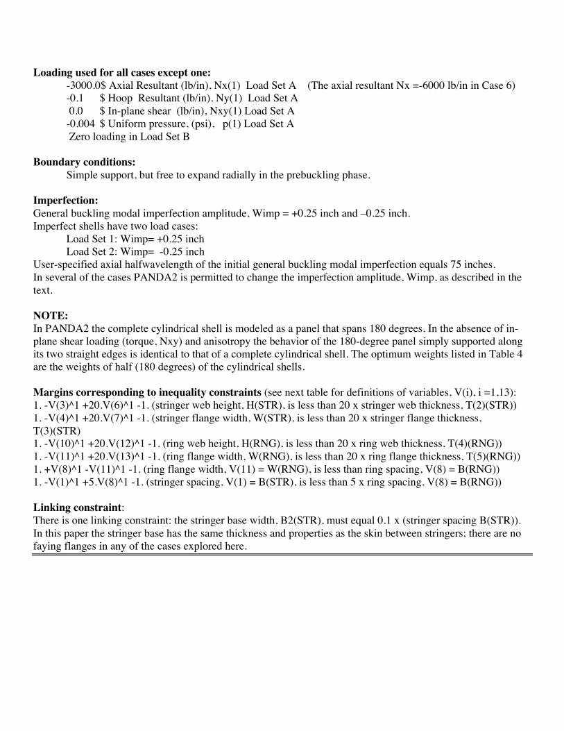
Loading used for all cases except one: -3000.0$ Axial Resultant (lb/in), Nx(1) Load Set A (The axial resultant Nx =-6000 lb/in in Case 6) -0.1 $ Hoop Resultant (lb/in), Ny(1) Load Set A 0.0 $ In-plane shear (lb/in), Nxy(1) Load Set A -0.004 $ Uniform pressure, (psi), p(1) Load Set A Zero loading in Load Set B
Boundary conditions:
Simple support, but free to expand radially in the prebuckling phase. Imperfection: General buckling modal imperfection amplitude, Wimp = +0.25 inch and –0.25 inch. Imperfect shells have two load cases:
Load Set 1: Wimp= +0.25 inch Load Set 2: Wimp= -0.25 inch
User-specified axial halfwavelength of the initial general buckling modal imperfection equals 75 inches. In several of the cases PANDA2 is permitted to change the imperfection amplitude, Wimp, as described in the text. NOTE: In PANDA2 the complete cylindrical shell is modeled as a panel that spans 180 degrees. In the absence of in-plane shear loading (torque, Nxy) and anisotropy the behavior of the 180-degree panel simply supported along its two straight edges is identical to that of a complete cylindrical shell. The optimum weights listed in Table 4 are the weights of half (180 degrees) of the cylindrical shells. Margins corresponding to inequality constraints (see next table for definitions of variables, V(i), i =1,13): 1. -V(3)^1 +20.V(6)^1 -1. (stringer web height, H(STR), is less than 20 x stringer web thickness, T(2)(STR)) 1. -V(4)^1 +20.V(7)^1 -1. (stringer flange width, W(STR), is less than 20 x stringer flange thickness, T(3)(STR) 1. -V(10)^1 +20.V(12)^1 -1. (ring web height, H(RNG), is less than 20 x ring web thickness, T(4)(RNG)) 1. -V(11)^1 +20.V(13)^1 -1. (ring flange width, W(RNG), is less than 20 x ring flange thickness, T(5)(RNG)) 1. +V(8)^1 -V(11)^1 -1. (ring flange width, V(11) = W(RNG), is less than ring spacing, V(8) = B(RNG)) 1. -V(1)^1 +5.V(8)^1 -1. (stringer spacing, V(1) = B(STR), is less than 5 x ring spacing, V(8) = B(RNG)) Linking constraint: There is one linking constraint: the stringer base width, B2(STR), must equal 0.1 x (stringer spacing B(STR)). In this paper the stringer base has the same thickness and properties as the skin between stringers; there are no faying flanges in any of the cases explored here.
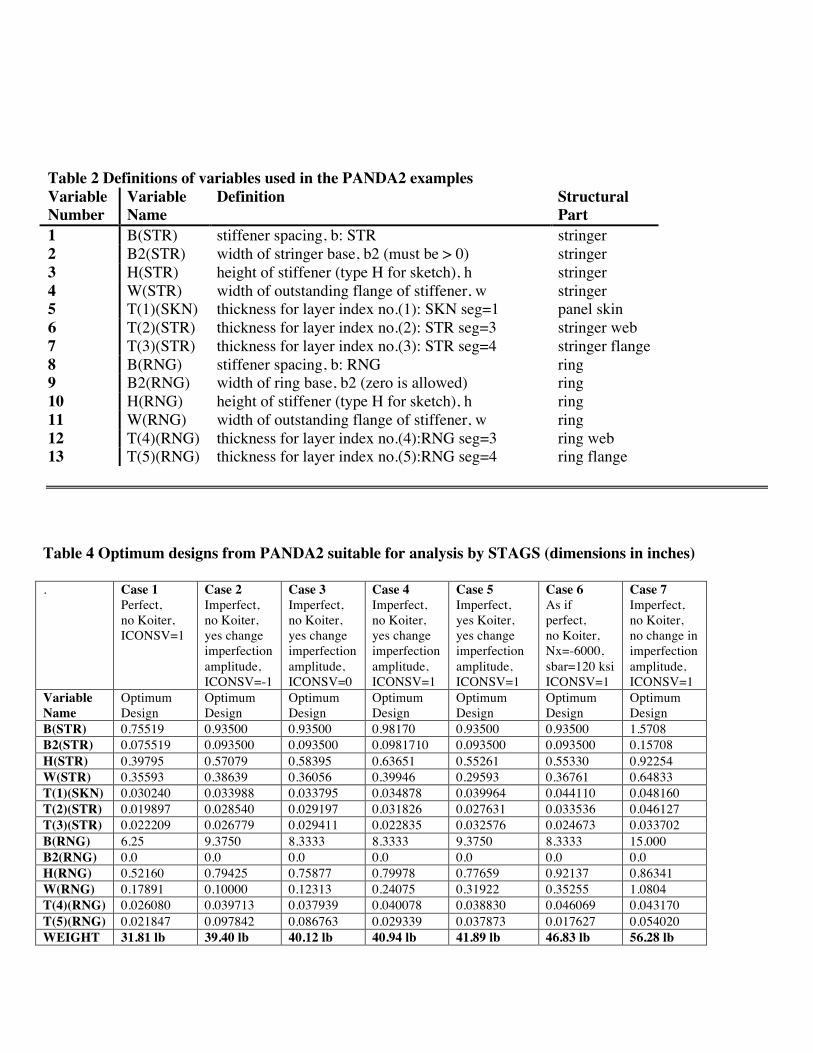
Table 2 Definitions of variables used in the PANDA2 examples Variable Number
Variable Name
Definition Structural Part
1 B(STR) stiffener spacing, b: STR stringer 2 B2(STR) width of stringer base, b2 (must be > 0) stringer 3 H(STR) height of stiffener (type H for sketch), h stringer 4 W(STR) width of outstanding flange of stiffener, w stringer 5 T(1)(SKN) thickness for layer index no.(1): SKN seg=1 panel skin 6 T(2)(STR) thickness for layer index no.(2): STR seg=3 stringer web 7 T(3)(STR) thickness for layer index no.(3): STR seg=4 stringer flange 8 B(RNG) stiffener spacing, b: RNG ring 9 B2(RNG) width of ring base, b2 (zero is allowed) ring 10 H(RNG) height of stiffener (type H for sketch), h ring 11 W(RNG) width of outstanding flange of stiffener, w ring 12 T(4)(RNG) thickness for layer index no.(4):RNG seg=3 ring web 13 T(5)(RNG) thickness for layer index no.(5):RNG seg=4 ring flange
Table 4 Optimum designs from PANDA2 suitable for analysis by STAGS (dimensions in inches)
. Case 1 Perfect, no Koiter, ICONSV=1
Case 2 Imperfect, no Koiter, yes change imperfection amplitude, ICONSV=-1
Case 3 Imperfect, no Koiter, yes change imperfection amplitude, ICONSV=0
Case 4 Imperfect, no Koiter, yes change imperfection amplitude, ICONSV=1
Case 5 Imperfect, yes Koiter, yes change imperfection amplitude, ICONSV=1
Case 6 As if perfect, no Koiter, Nx=-6000, sbar=120 ksi ICONSV=1
Case 7 Imperfect, no Koiter, no change in imperfection amplitude, ICONSV=1
Variable Name
Optimum Design
Optimum Design
Optimum Design
Optimum Design
Optimum Design
Optimum Design
Optimum Design
B(STR) 0.75519 0.93500 0.93500 0.98170 0.93500 0.93500 1.5708 B2(STR) 0.075519 0.093500 0.093500 0.0981710 0.093500 0.093500 0.15708 H(STR) 0.39795 0.57079 0.58395 0.63651 0.55261 0.55330 0.92254 W(STR) 0.35593 0.38639 0.36056 0.39946 0.29593 0.36761 0.64833 T(1)(SKN) 0.030240 0.033988 0.033795 0.034878 0.039964 0.044110 0.048160 T(2)(STR) 0.019897 0.028540 0.029197 0.031826 0.027631 0.033536 0.046127 T(3)(STR) 0.022209 0.026779 0.029411 0.022835 0.032576 0.024673 0.033702 B(RNG) 6.25 9.3750 8.3333 8.3333 9.3750 8.3333 15.000 B2(RNG) 0.0 0.0 0.0 0.0 0.0 0.0 0.0 H(RNG) 0.52160 0.79425 0.75877 0.79978 0.77659 0.92137 0.86341 W(RNG) 0.17891 0.10000 0.12313 0.24075 0.31922 0.35255 1.0804 T(4)(RNG) 0.026080 0.039713 0.037939 0.040078 0.038830 0.046069 0.043170 T(5)(RNG) 0.021847 0.097842 0.086763 0.029339 0.037873 0.017627 0.054020 WEIGHT 31.81 lb 39.40 lb 40.12 lb 40.94 lb 41.89 lb 46.83 lb 56.28 lb
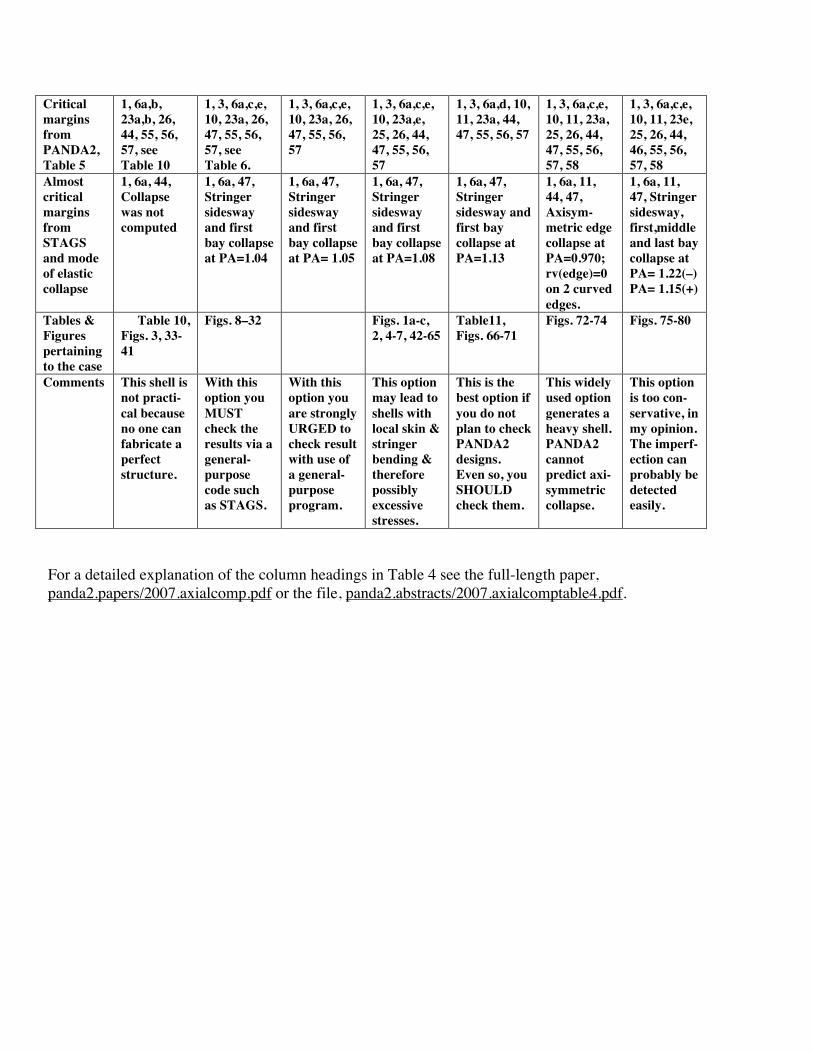
Critical margins from PANDA2, Table 5
1, 6a,b, 23a,b, 26, 44, 55, 56, 57, see Table 10
1, 3, 6a,c,e, 10, 23a, 26, 47, 55, 56, 57, see Table 6.
1, 3, 6a,c,e, 10, 23a, 26, 47, 55, 56, 57
1, 3, 6a,c,e, 10, 23a,e, 25, 26, 44, 47, 55, 56, 57
1, 3, 6a,d, 10, 11, 23a, 44, 47, 55, 56, 57
1, 3, 6a,c,e, 10, 11, 23a, 25, 26, 44, 47, 55, 56, 57, 58
1, 3, 6a,c,e, 10, 11, 23e, 25, 26, 44, 46, 55, 56, 57, 58
Almost critical margins from STAGS and mode of elastic collapse
1, 6a, 44, Collapse was not computed
1, 6a, 47, Stringer sidesway and first bay collapse at PA=1.04
1, 6a, 47, Stringer sidesway and first bay collapse at PA= 1.05
1, 6a, 47, Stringer sidesway and first bay collapse at PA=1.08
1, 6a, 47, Stringer sidesway and first bay collapse at PA=1.13
1, 6a, 11, 44, 47, Axisym-metric edge collapse at PA=0.970; rv(edge)=0 on 2 curved edges.
1, 6a, 11, 47, Stringer sidesway, first,middle and last bay collapse at PA= 1.22(–) PA= 1.15(+)
Tables & Figures pertaining to the case
Table 10, Figs. 3, 33-41
Figs. 8–32 Figs. 1a-c, 2, 4-7, 42-65
Table11, Figs. 66-71
Figs. 72-74 Figs. 75-80
Comments This shell is not practi-cal because no one can fabricate a perfect structure.
With this option you MUST check the results via a general-purpose code such as STAGS.
With this option you are strongly URGED to check result with use of a general-purpose program.
This option may lead to shells with local skin & stringer bending & therefore possibly excessive stresses.
This is the best option if you do not plan to check PANDA2 designs. Even so, you SHOULD check them.
This widely used option generates a heavy shell. PANDA2 cannot predict axi-symmetric collapse.
This option is too con-servative, in my opinion. The imperf-ection can probably be detected easily.
For a detailed explanation of the column headings in Table 4 see the full-length paper, panda2.papers/2007.axialcomp.pdf or the file, panda2.abstracts/2007.axialcomptable4.pdf.
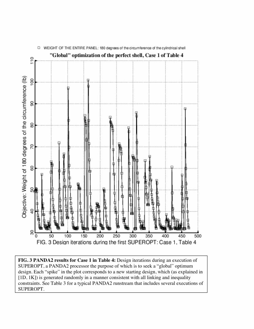
FIG. 3 PANDA2 results for Case 1 in Table 4: Design iterations during an execution of SUPEROPT, a PANDA2 processor the purpose of which is to seek a “global” optimum design. Each “spike” in the plot corresponds to a new starting design, which (as explained in [1D, 1K]) is generated randomly in a manner consistent with all linking and inequality constraints. See Table 3 for a typical PANDA2 runstream that includes several executions of SUPEROPT.
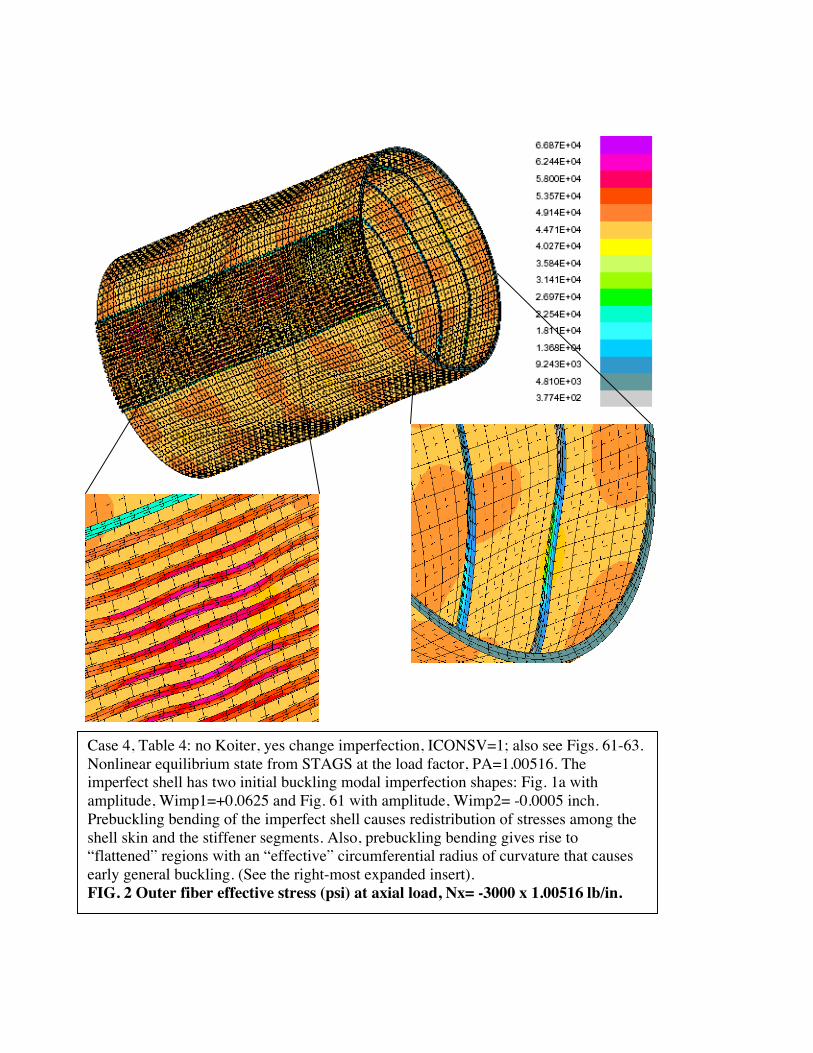
Case 4, Table 4: no Koiter, yes change imperfection, ICONSV=1; also see Figs. 61-63. Nonlinear equilibrium state from STAGS at the load factor, PA=1.00516. The imperfect shell has two initial buckling modal imperfection shapes: Fig. 1a with amplitude, Wimp1=+0.0625 and Fig. 61 with amplitude, Wimp2= -0.0005 inch. Prebuckling bending of the imperfect shell causes redistribution of stresses among the shell skin and the stiffener segments. Also, prebuckling bending gives rise to “flattened” regions with an “effective” circumferential radius of curvature that causes early general buckling. (See the right-most expanded insert). FIG. 2 Outer fiber effective stress (psi) at axial load, Nx= -3000 x 1.00516 lb/in.
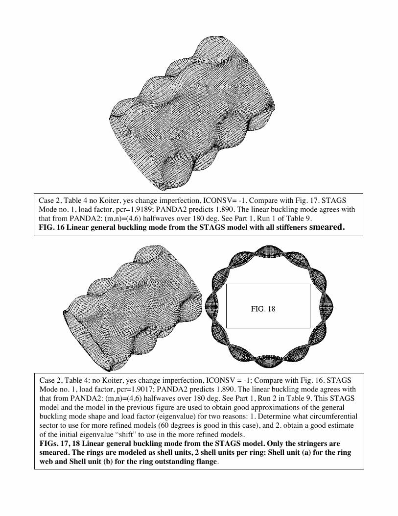
FIG. 18 End view
Case 2, Table 4 no Koiter, yes change imperfection, ICONSV= -1. Compare with Fig. 17. STAGS Mode no. 1, load factor, pcr=1.9189; PANDA2 predicts 1.890. The linear buckling mode agrees with that from PANDA2: (m,n)=(4,6) halfwaves over 180 deg. See Part 1, Run 1 of Table 9. FIG. 16 Linear general buckling mode from the STAGS model with all stiffeners smeared.
Case 2, Table 4: no Koiter, yes change imperfection, ICONSV = -1; Compare with Fig. 16. STAGS Mode no. 1, load factor, pcr=1.9017; PANDA2 predicts 1.890. The linear buckling mode agrees with that from PANDA2: (m,n)=(4,6) halfwaves over 180 deg. See Part 1, Run 2 in Table 9. This STAGS model and the model in the previous figure are used to obtain good approximations of the general buckling mode shape and load factor (eigenvalue) for two reasons: 1. Determine what circumferential sector to use for more refined models (60 degrees is good in this case), and 2. obtain a good estimate of the initial eigenvalue “shift” to use in the more refined models. FIGs. 17, 18 Linear general buckling mode from the STAGS model. Only the stringers are smeared. The rings are modeled as shell units, 2 shell units per ring: Shell unit (a) for the ring web and Shell unit (b) for the ring outstanding flange.
FIG. 18
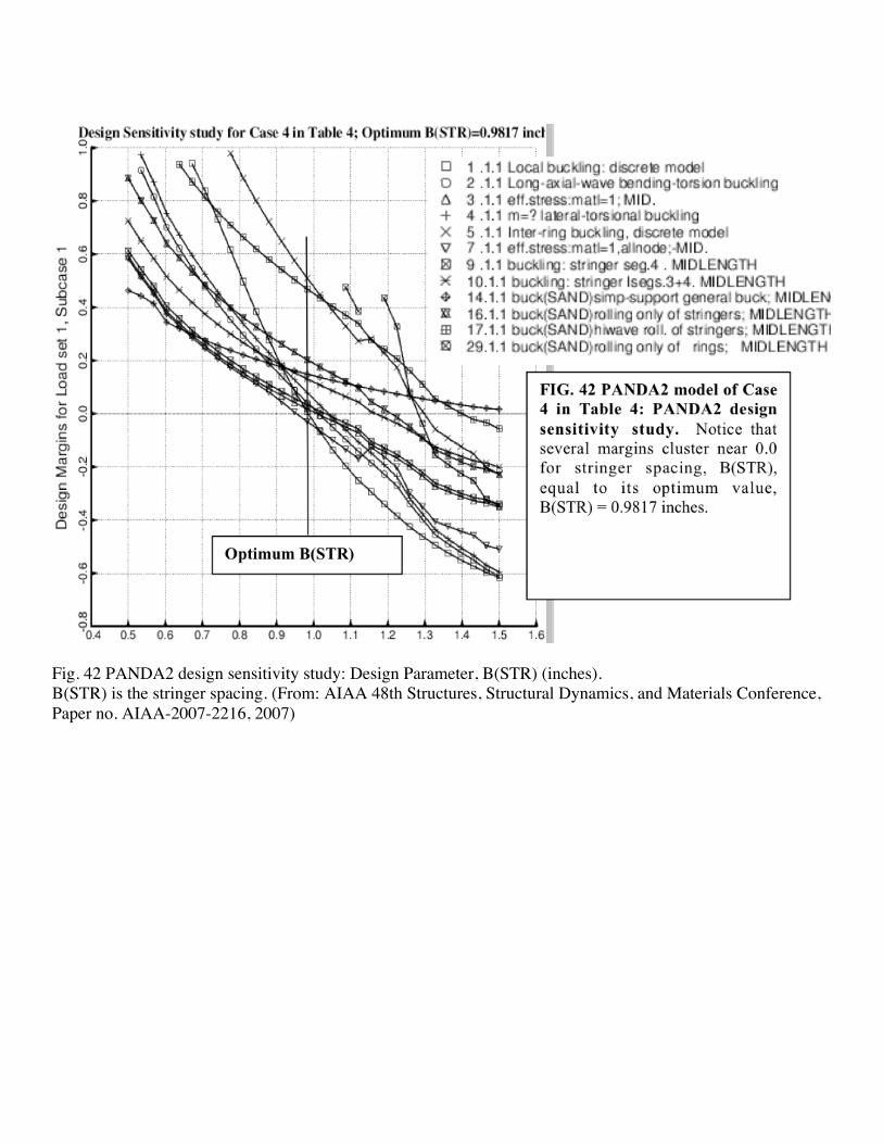
Fig. 42 PANDA2 design sensitivity study: Design Parameter, B(STR) (inches). B(STR) is the stringer spacing. (From: AIAA 48th Structures, Structural Dynamics, and Materials Conference, Paper no. AIAA-2007-2216, 2007)