Embed Size (px)
Citation preview

Vol-3 Issue-4 2017 IJARIIE-ISSN (O)-2395-4396
6272 www.ijariie.com 2150
MULTIDISPLAY-SYSTEM USING CC2500
SNEHAL DHONE, SUCHANCHI RAUT,GUNJAN KADU,SANKET ZADE
Snehhal Dhone, Electronics and Telecommunication Engineering, SVPCET, Nagpur Maharashtra, India
Susanchi Raut Electronics and Telecommunication Engineering, SVPCET, Nagpur Maharashtra, India
Gunjan Kadu, Electronics and Telecommunication Engineering, SVPCET, Nagpur Maharashtra, India
Sanket Zade,, Electronics and Telecommunication Engineering, SVPCET, Nagpur Maharashtra, India
ABSTRACT In the past, various techniques were used serial communication. Most commonly used techniques
included wired networks for multiple transmissions and reception. The main disadvantage of these
methods is that they were complicated and not portable. Hence, to get better accuracy, reliability, we used
wireless RF module which could ease the process of multiple transmission. The developed system consists of two
RF modules (minimum), a TTL converter, two Arduino Uno boards (minimum), two LCD displays (minimum)
and a personal computer or laptop. The three RF modules used in this project are all CC2500. Initially, the CCs
were configures using Flash Magic software in such a way that one of them acted as transmitter and the
other two act as receivers. But for the purpose of cost cutting, the transmitting CC was replaced with a TTL
converter which served the same purpose as of a transmitting CC. The PC is then used to give commands or
transmit message signals. Before that, we interface this set up with the two Arduino boards at the receiving
end along with two LCD displays. The transmitted data is received by the two CCs and then it goes to the
Arduino, which serves as an intermediate between the PC and the CC. And finally, the sent signal is received at
the VDU (visual display unit) and is flashed on the screens of the LCD.
Keyword: - CC2500,Visual Display Unit, RF Module
1. Introduction
Multi-display setups are very common in investment banks, particularly in market making, where
they allow the simultaneous display of several screens of prices as reference data, allowing the trader to keep an
eye on the market. Setups of 6 displays (2×3: 2 rows of 3) are common on interest rate trading desks, which
involve many numbers, while 8 displays (2×4: 2 rows of 4) are not uncommon. Financial multi-
display setups may also incorporate Bloomberg Terminals, or these may be adjunct to the main display. Now
that multi-monitor setups are more budget-friendly, it is not uncommon to see a wide range of business
professionals using multiple monitors to increase visual area. This advantage helps promote the concept
of a paperless by increasing the quantity of simultaneous media that can be viewed digitally, although
the advantage of viewing two documents simultaneously is also feasible on many larger widescreen monitors.
Multi- monitor gaming/simulation is also becoming more common; however, the hardware expense can be a
limiting factor. With multiple monitors present, each screen will have its own graphics buffer.
Because of its increasing popularity and the concept of paperless world, we have come up
with the idea of a multiple display system using an economical and reliable RF module. CC2500 satisfies all the
above mentioned requirements and works within a range as good as 25 metres with frequency of 2400-2483.5
MHz used in ISM/SRD band systems. The system will be developed to serially transmit data to multiple stations
and display it on their respective screens. Ideas for further developments of this multi-display system are put
forth.

Vol-3 Issue-4 2017 IJARIIE-ISSN (O)-2395-4396
6272 www.ijariie.com 2151
2. Description We reached the ultimate idea with the help of our project guide to design a multi-display system
using an RF module. Multi-monitor, also called multi- display and multi-head, is the use
of multiple physical display devices, such as monitors, televisions, and projectors, in order to increase
the area available for computer programs running on a single computer system. Research studies show that,
depending on the type of work, multi-head may increase the productivity by up to 50-70%.
Support for a multi-monitor setup is either achieved by installing multiple graphics cards into one
computer or by special display controllers that have the ability to feed multiple monitors independently with a
signal. Monitors supporting Display Port allow driving multiple monitors from only one external clock.
Display Port version 1.2 supports Multi- Stream Transport; this makes it possible to drive multiple displays on
one single Display Port connector using a multi-head cable or loop through.
The project is based on microcontroller board designs, using various microcontrollers. These systems
provide sets of digital and analog I/O pins that can interface to various expansion boards and other
circuits. The boards feature serial communication interfaces, including Universal Serial Bus (USB) on some
models, for loading programs from personal computers. For programming the microcontrollers, the Arduino
project provides an integrated development environment (IDE) based on a programming language named
Processing, which also supports the languages C and C++.
Here, we configure the two RF modules (CC) and interface it with LCDs and Arduino board so as to
obtain desired output.
3. COMPONENTS
3.1. CC2500 (RF MODULE)
3.1.1. DESCRIPTION:
The CC2500 is a low-cost 2.4GHz transceiver designed for very low-power wireless applications.
The circuit is intended for the 2400-2483.5 MHz ISM (Industrial, Scientific and Medical) and SRD (Short Range
Device) frequency band.
The RF transceiver is integrated with a highly configurable baseband modem. The modem supports various
modulation formats and has a configurable data rate up to 500 k Baud. CC2500 provides extensive hardware
support for packet handling, data buffering, burst transmissions, clear channel assessment, link quality
indication and wake-on-radio.
The main operating parameters and the 64-byte transmit/receive FIFOs of CC2500 can be controlled via an
SPI interface. In a typical system, the CC2500 will be used together with a microcontroller and a few
additional passive components.

Vol-3 Issue-4 2017 IJARIIE-ISSN (O)-2395-4396
6272 www.ijariie.com 2152
Fig 3.1(a). CC2500 RF module
3.1.2. FEATURES:
RF Performance
High sensitivity (-104 dBm at 2.4 k Baud, 1% packet error rate)
Low current consumption (13.3 mA in RX, 250 k Baud, input well above sensitivity limit)
Programmable output power up to +1 dBm
Excellent receiver selectivity and blocking performance
Programmable data rate from 1.2 to 500 k Baud
Frequency range: 2400 - 2483.5 MHz
Analog Features
OOK, 2-FSK, GFSK, and MSK supported
Suitable for frequency hopping and multichannel systems due to a fast settling frequency
synthesizer with 90 us settling time
Automatic Frequency Compensation (AFC) can be used to align the frequency synthesizer to
the received centre frequency
Integrated analog temperature sensor
Digital Features
Flexible support for packet oriented systems: On-chip support for sync word detection,
address check, flexible packet length, and automatic CRC handling
Efficient SPI interface: All registers can be programmed with one "burst" transfer
Digital RSSI output
Programmable channel filter bandwidth
Programmable Carrier Sense (CS) indicator

Vol-3 Issue-4 2017 IJARIIE-ISSN (O)-2395-4396
6272 www.ijariie.com 2153
Programmable Preamble Quality Indicator (PQI) for improved protection against false sync word
detection in random noise
Support for automatic Clear Channel Assessment (CCA) before transmitting (for listen-before-
talk systems)
Support for per-package Link Quality Indication (LQI)
Low-Power Features
400 nA SLEEP mode current consumption
Fast start-up time: 240 us from SLEEP to RX or TX mode (measured on EM design)
Wake-on-radio functionality for automatic low-power RX polling
Separate 64-byte RX and TX data FIFOs (enables burst mode data transmission)
General
Few external components: Complete on chip frequency synthesizer, no external filters or RF switch
needed
Green package: RoHS compliant and no antimony or bromine
Small size (QLP 4x4 mm package, 20 pins)
Suited for systems compliant with EN 300 328 and EN 300 440 class 2 (Europe), FCC CFR47
Part 15 (US), and ARIB STDT66 (Japan)
Support for asynchronous and synchronous serial receive/transmit mode for backwards
compatibility with existing radio communication protocols
APPLICATIONS
2400-2483.5 MHz ISM/SRD band systems
Consumer Electronics
Wireless game controllers
Wireless audio
Wireless keyboard and mouse
RF enabled remote controls
3.2. ARDUINO UNO
Arduino is an open-source platform used for building electronics projects. Arduino consists of both
a physical programmable circuit board (often referred to as a microcontroller) and a piece of
software, or IDE (Integrated Development Environment) that runs on your computer, used to write and upload
computer code to the physical board.
Vol-3 Issue-4 2017 IJARIIE-ISSN (O)-2395-4396
6272 www.ijariie.com 2154
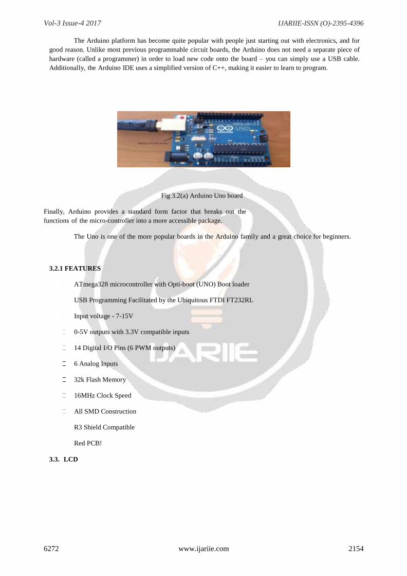
The Arduino platform has become quite popular with people just starting out with electronics, and for
good reason. Unlike most previous programmable circuit boards, the Arduino does not need a separate piece of
hardware (called a programmer) in order to load new code onto the board – you can simply use a USB cable.
Additionally, the Arduino IDE uses a simplified version of C++, making it easier to learn to program.
Fig 3.2(a) Arduino Uno board
Finally, Arduino provides a standard form factor that breaks out the
functions of the micro-controller into a more accessible package.
The Uno is one of the more popular boards in the Arduino family and a great choice for beginners.
3.2.1 FEATURES
ATmega328 microcontroller with Opti-boot (UNO) Boot loader
USB Programming Facilitated by the Ubiquitous FTDI FT232RL
Input voltage - 7-15V
0-5V outputs with 3.3V compatible inputs
14 Digital I/O Pins (6 PWM outputs)
6 Analog Inputs
32k Flash Memory
16MHz Clock Speed
All SMD Construction
R3 Shield Compatible
Red PCB!
3.3. LCD
Vol-3 Issue-4 2017 IJARIIE-ISSN (O)-2395-4396
6272 www.ijariie.com 2155
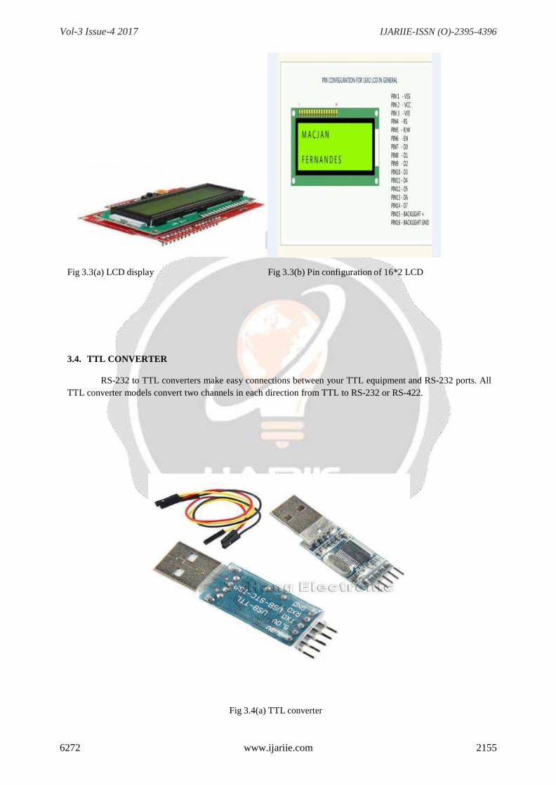
Fig 3.3(a) LCD display Fig 3.3(b) Pin configuration of 16*2 LCD
3.4. TTL CONVERTER
RS-232 to TTL converters make easy connections between your TTL equipment and RS-232 ports. All
TTL converter models convert two channels in each direction from TTL to RS-232 or RS-422.
Fig 3.4(a) TTL converter

Vol-3 Issue-4 2017 IJARIIE-ISSN (O)-2395-4396
6272 www.ijariie.com 2156
04. IMPLEMENTATION
4.1. SOFTWARE ASPECTS
4.1.1 Software tools
A. Flash MagicFlash Magic is Windows software from the Embedded Systems Academy that allows easy access to
all the ISP features provided by the devices. These features include
Erasing the Flash memory (individual blocks or the whole device)
Programming the Flash memory
Modifying the Boot Vector and Status Byte
Reading Flash memory
Performing a blank check on a section of Flash memory
Reading the signature bytes
Reading and writing the security bits
Direct load of a new baud rate (high speed communications)
Sending commands to place device in Boot loader mode
Flash Magic provides a clear and simple user interface to these features. Under Windows, only
one application may have access the COM Port at any one time, preventing other applications from using the
COM Port.
Flash Magic only obtains access to the selected COM Port when ISP operations are being performed.
This means that other applications that need to use the COM Port, such as debugging tools, may be used while
Flash Magic is loaded.
To establish communication between CC2500s follow the following steps for configuring CC2500:
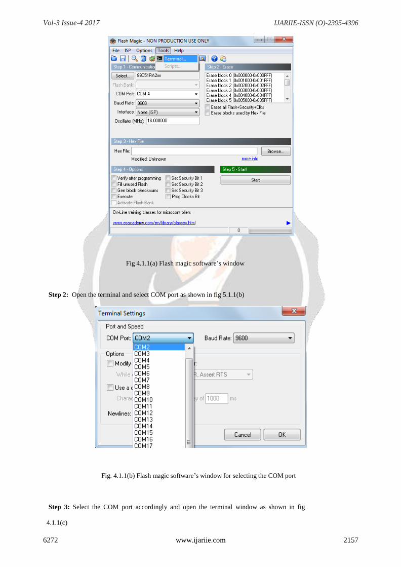
Step 1: Open the Flash magic Software and go to tools as shown in fig. 4.1.1(a).
Vol-3 Issue-4 2017 IJARIIE-ISSN (O)-2395-4396
6272 www.ijariie.com 2157
Fig 4.1.1(a) Flash magic software’s window
Step 2: Open the terminal and select COM port as shown in fig 5.1.1(b)
Fig. 4.1.1(b) Flash magic software’s window for selecting the COM port
Step 3: Select the COM port accordingly and open the terminal window as shown in fig
4.1.1(c)
Vol-3 Issue-4 2017 IJARIIE-ISSN (O)-2395-4396
6272 www.ijariie.com 2158
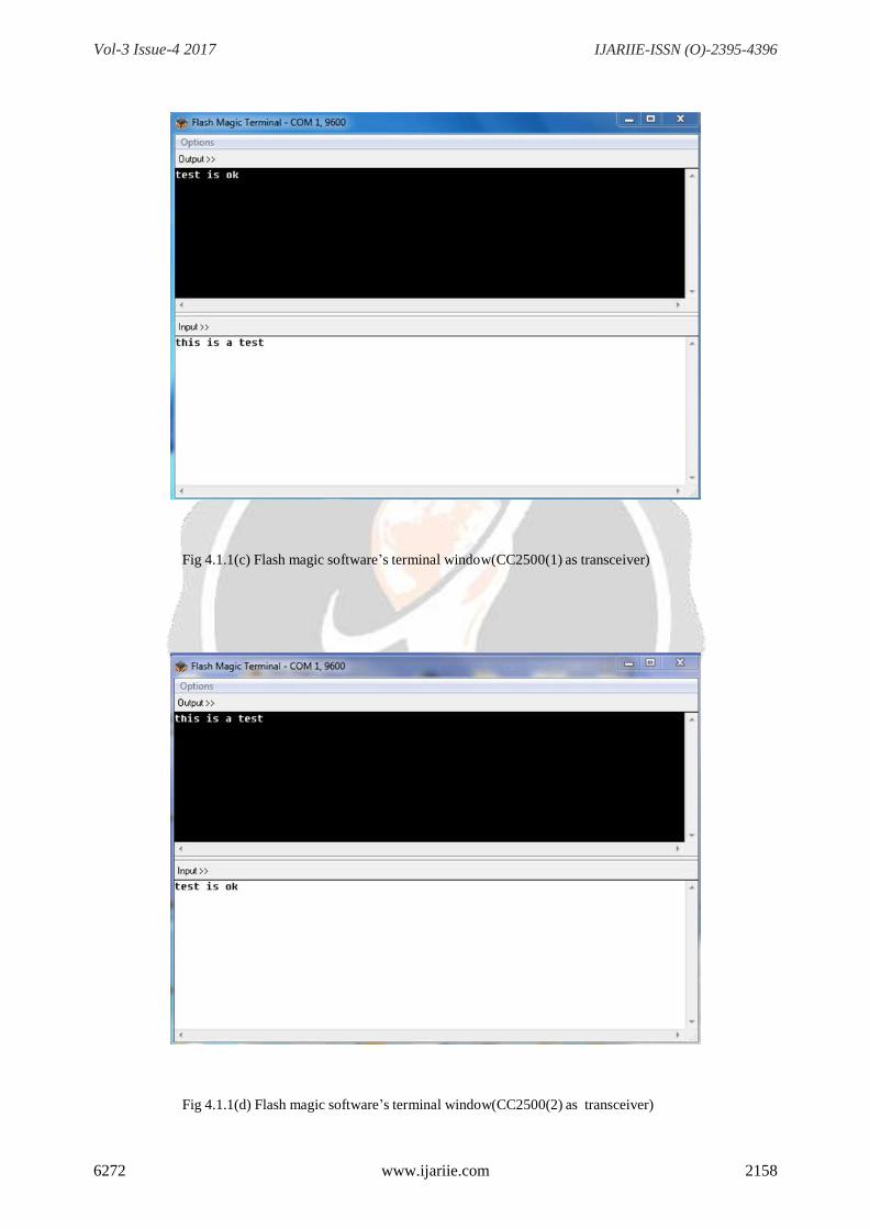
Fig 4.1.1(c) Flash magic software’s terminal window(CC2500(1) as transceiver)
Fig 4.1.1(d) Flash magic software’s terminal window(CC2500(2) as transceiver)

Vol-3 Issue-4 2017 IJARIIE-ISSN (O)-2395-4396
6272 www.ijariie.com 2159
B. Arduino(IDE)
Arduino is an open-source prototyping platform based on easy to use hardware and software. Arduino
boards are able to read inputs- light on a sensor, a finger on a button or a Twitter message- and turn it into an
output-activating a motor, turning ON and LED, publishing something online. You can tell your board what to
do by sending a set of instructions to the microcontroller on the board. To do so you use the Arduino
pogramming language(based on wring) and the Arduino Software(IDE) based on processing.
Fig 4.1.1(e) Arduino(IDE) Software window

Vol-3 Issue-4 2017 IJARIIE-ISSN (O)-2395-4396
6272 www.ijariie.com 2160
4.1.2 Design steps
#include <LiquidCrystal.h> LiquidCrystal
lcd(12, 11, 5, 4, 3, 2); void setup()
{
lcd.begin(16, 2);
Serial.begin(9600);
pinMode(9,OUTPUT);
digitalWrite(9,HIGH);
pinMode(8,OUTPUT);
digitalWrite(8,LOW);
pinMode(13,OUTPUT);
digitalWrite(13,LOW);
}
void loop()
{
if (Serial.available())
{
delay(100);
lcd.clear();
while (Serial.available() > 0)
{
lcd.write(Serial.read());
}
}
}
Vol-3 Issue-4 2017 IJARIIE-ISSN (O)-2395-4396
6272 www.ijariie.com 2161
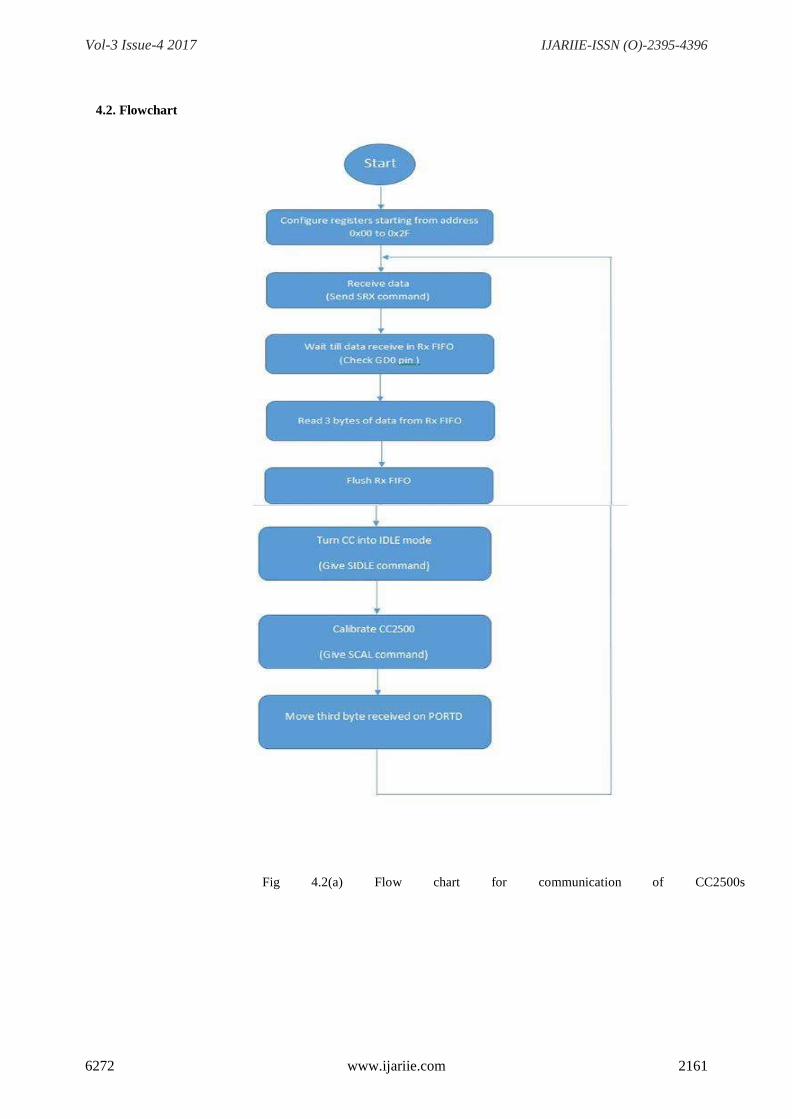
4.2. Flowchart
Fig 4.2(a) Flow chart for communication of CC2500s
Vol-3 Issue-4 2017 IJARIIE-ISSN (O)-2395-4396
6272 www.ijariie.com 2162
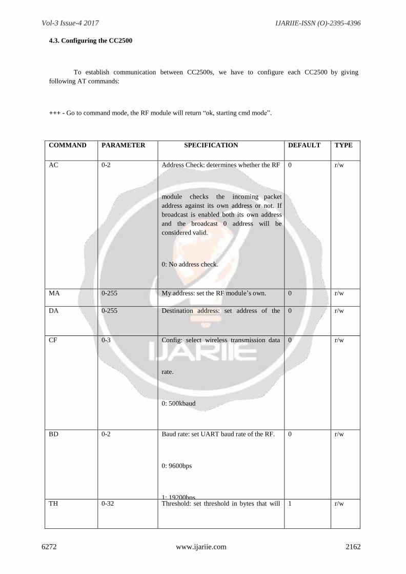
4.3. Configuring the CC2500
To establish communication between CC2500s, we have to configure each CC2500 by giving
following AT commands:
+++ - Go to command mode, the RF module will return “ok, starting cmd mode”.
COMMAND PARAMETER SPECIFICATION DEFAULT TYPE
AC 0-2 Address Check: determines whether the RF
module checks the incoming packet
address against its own address or not. If
broadcast is enabled both its own address
and the broadcast 0 address will be
considered valid.
0: No address check.
1: Address check, no broadcast.
2: Address check and broadcast.
0 r/w
MA 0-255 My address: set the RF module’s own. 0 r/w
DA 0-255 Destination address: set address of the
receiver.
0 r/w
CF 0-3 Config: select wireless transmission data
rate.
0: 500kbaud
1: 250kbaud
2: 10kbaud
3: 2.4kbaud
0 r/w
BD 0-2 Baud rate: set UART baud rate of the RF.
0: 9600bps
1: 19200bps
2: 38400bps
0 r/w
TH 0-32 Threshold: set threshold in bytes that will
trigger RF to start transmission.
1 r/w

Vol-2 Issue-1 2016 IJARIIE-ISSN(O)-2395-4396
6272 www.ijariie.com 2163
OF 0-3 0: payload only.
1: source, dest, payload.
2: payload len, source, dest, payload,
rssi, lqi.
3: same as 2 except for payload as
decimal and separated by comma’s.
0 r/w
MD 0-2 Mode: set working mode of the RF.
0: Transceive
1: Transmit only
2: Receive only
0 r/w
O 0 Online: return to data mode. w
CL 0-255 To select device channel ID. 0 r/w
RS - Restore: restore the configuration to
default settings.
- -

Vol-2 Issue-1 2016 IJARIIE-ISSN(O)-2395-4396
6272 www.ijariie.com 2164
4.4. Circuit diagram
Fig 4.4(a) Circuit diagram for Transmitter

Vol-2 Issue-1 2016 IJARIIE-ISSN(O)-2395-4396
6272 www.ijariie.com 2165
Fig 4.4(b) Circuit diagram for Receiver
5. RESULT
The study regarding the project in every aspect is done and the expected output from the device has
been generated. We have successfully designed a working circuit which displays received data that has
been transmitted by the one CC2500 in transmitter mode at multiple destinations where other CC2500s in
receiver mode are present i.e. one transmitter and multiple receivers.
The information you want to share with your friends or for office stuff is sent from the transmitter and received
at multiple receivers i.e. parallel communication, thus satisfying the objective of our project.
Vol-2 Issue-1 2016 IJARIIE-ISSN(O)-2395-4396
6272 www.ijariie.com 2166
6. CONCLUSION
The main objective of this project was to design an economical and reliable trans-receiving system using RF
technology which could be easily incorporated in the limited premises of an office or educational building.
Other methods used for serial communication are costly and have lesser range. In comparison, the use of
CC2500 gives more promising results as it is highly reliable for serial communication
7. REFERENCES
1. https://www.arduino.cc/en/main/arduinoBoardUno
2. Internetofthingsagenda.techtarget.com/definition/cc2500
3. www.engineersgarage.com/.../arduino/how-to-interface-cc2500-with-arduino
4. www.arduino.cc/en/tutorial


![[RF Communication Release] 2012 - Robosoft Systems · [RF Communication Release] 2012 ... see CC2500 datasheet for details. ... tion using CC2500 based RF modules. Configure the mod-](https://img.dokumen.tips/doc/110x75/5b2cf2d27f8b9abb6e8b92d3/rf-communication-release-2012-robosoft-rf-communication-release-2012-.jpg)