Embed Size (px)
Citation preview
iii
ABSORPTION CHILLR- DESIGN AND OPTIMIZATION OF
GENERATOR AND CONDENSER
SEYEDAHMAD TOHIDI
A thesis submitted in fulfillment of the
requirements for the award of the degree of
Master of Engineering (Mechanical)
Faculty of Mechanical Engineering
Universiti Teknologi Malaysia
JANUARY 2012

ii
To my father, mother, sister and brother for their enormous financial and emotional supports
iii
ACKNOWLEDGEMENTS
I would like to express my sincere appreciation to Prof .Dr. Md Nor
Musa as my supervisor and his support, guidance, sharing his experience
and encouragement throughout of my research. Without his support and
suggestions, t his thesis would not be as it is presented now.
I would also like to thank to my parents, who have always supported me
throughout my life.

iv
ABSTRACT
Since absorption chillers are more commodiouse than compression chillers,
the usage of them increases these days. In comparison with compression chillers these
type of chillers have lower coefficient of performance (COP). By improving the
performance of each component of these chillers such as generator, condenser, heat
exchanger and absorber the COP will increase. In this study , after designing generator
and condenser an optimization was done on these two components by using genetic
algorithm(GA). The parameters which consider for optimization were tube diameter,
shell diameter and baffle spacing.The main purpose is to find the optimum amount of
these three parameters so that the COP can be increased and the cost of absorption
chillers is decreased simultaneously. After optimization the COP of the chiller increases
from 0.62 to 0.66 and the price of chiller is reduced. These results indicate that GA is a
successful optimization technique for the optimization of generator and condenser in
absorption chillers.
v
ABSTRAK
Sejak pendingin penyerapan commodiouse lebih daripada pendingin mampatan,
penggunaan mereka meningkat ini hari perbandingan.in dengan pendingin pemampatan-
jenis penyejuk mempunyai pekali prestasi yang lebih rendah (COP). Dengan
meningkatkan prestasi setiap komponen ini penyejuk seperti penjana, pemeluwap,
penukar haba dan penyerap COP akan meningkat. Dalam kajian ini, selepas mereka
bentuk penjana dan pemeluwap pengoptimuman yang dilakukan ke atas komponen
kedua-dua dengan menggunakan algorythm genetik. Parameter yang
mempertimbangkan untuk aptimization diameter tiub, diameter shell dan maksud
sesekat spacing.the utama adalah untuk mencari jumlah optimum thease tiga parameter
supaya kenaikan COP dan kos pendingin penyerapan berkurangan simoltaneously.
Selepas pengoptimuman COP kenaikan pendingin 0.62-0.66 dan harga pendingin
mengurangkan. Keputusan ini menunjukkan bahawa GA teknik pengoptimuman yang
berjaya untuk pengoptimuman penjana dan pemeluwap dalam pendingin penyerapan.
vi
TABLE OF CONTENTS
CHAPTER TITLE PAGE
DECLARATION ii
DEDICATION iii
ACKNOWLEDGEMENTS iv
ABSTRACT v
ABSTRAK vi
TABLE OF CONTENTS vii
LIST OF TABLES viii
LIST OF FIGURES ix
1 INTRODUCTION 1
1.1 History of refrigeration 1
1.2 Why absorption chillers 2
1.3 What is absorption refrigeration 3
1.4 Some factors that should be conceder for choosing the refrigerant 4
1.5 A comparison of the mechanical coolers and absorption chiller 5
1.6 Absorption chiller disadvantages 5

vii
1.7 Absorption chiller refrigeration cycle 6
1.8 "Indirect fire" and "direct fire" absorption chillers 7
1.9 Commercially division of absorption chillers 7
1.10 Different type of water chillers 10
1.11 Generator 11
1.12 Condenser 12
1.13 Shell and tube heat exchangers 12
1.14 Combined heat and power (CHP) 15
1.15 Problem statement 16
1.16 Objectives 17
1.17 Scopes 17
2 LITERATURE REVIEW 18
3 METHODOLOGY 27
3.1 Finding heat transfer coefficient 27
3.1.1 One-phase heat transfer inside the tubes 28
3.1.2 Calculating heat transfer on the sell side of tub 29
3.1.3 Heat transfer during boiling 30
3.1.4 Heat transfer during condensation 32
3.1.5 Heat transfer in the tubes of generator 36
3.2 Calculating the pressure drop 37
3.2.1 Calculating the pressure drop in tube side 37
3.2.2 Calculating the pressure drop in the shell side 38
3.3 Designing process 39
3.4 Optimization process 39
viii
3.5 Genetic algorithm 44
3.5.1 A brief history of gas 45
3.5.2 What is a genetic algorithm 48
3.5.3 Methods of representation 49
3.5.4 Methods of selection 50
3.5.5 Methods of change 52
4 RESULT AND DISCUSSION 53
4.1 Thermodynamic analysis of the cycle 53
4.1.1 Calculation of mass flow rate and finding . refrigerant.properties 56
4.1.2 Calculating the properties and mass flow rate of . the solution in different step point of the cycle 59
4.1.3 Calculation of the heart transfer of each. . component in the cycle 61
4.1.4 Calculating mass flow rate for cooling tower, . cooled water and vapor consumption 65
4.1.5 Cycle coefficient of performance 66
4.2 Designing the condenser 66
4.3 Designing the generator 73
4.4 Optimization of condenser 78
4.5 Optimization of generator 87
5 CONCLUSION 96
REFERENCES 97
ix
LIST OF TABLES
TABLE NO. TITLE PAGE
1-1 A comparison of two solutions that can be used in refrigeration cycle 4
1-2 Comparison of COP and heat source temperature in single, double and . triple effect absorp 9
4-1 Two coefficients that are used to find tube numbers according to tube pass 80
4-2 A comparison between the optimized condenser and designed one 87
4-3 Two coefficients that are used to find tube numbers according to tube pass 89
4-4 A comparison between the optimized and designed generator 95
x
LIST OF FIGURES
FIGURE NO TITLE PAGE
1-1 Single effect absorption cycle 8
1-2 two-dimensional model of the kettle reboiler shell side thermal- hydraulics 11
1-3 Diagram of a typical water-cooled surface condenser 12
3-1 Film condensation on the tube 32
3-2 The different way that condensate will flow toward the lower tubes due to . gravity 33
3-3 Triangular (30°) and square (90°) layout for tubes 35
3-4 The graphs for the cost function of condenser and generator 42
3-5 Three simple program trees of the kind normally used in genetic . programming 49
3-6 Crossover and mutation 52
4-1 SSE100 absorption chillers working cycle 54
4-2 SSE100 absorption chillers diagram of P-T-X [12] 55
4-3 Kettle type reboiler 74
4-4 Optimum tube diameter for condenser 85
4-5 Optimum shell diameter for condenser 85
4-6 Optimum baffle spacing for condenser 86
xi
4-7 Best fitness value for optimizing condenser 86
4-8 Optimum tube diameter for generator 93
4-9 Optimum shell diameter for generator 93
4-10 Optimum baffle spacing for generator 94
4-11 Best fitness value for optimizing generator 94

xii
LIST OF SYMBOLS
Re - Reynolds number
Pr - Prandtl number
Nu - Dimensionless coefficient of heat transfer
�̇ - Mass flow rate
G - Mass flux
S - Flow surface
�� - Tube pass
�� - Tube numbers
L - Length
D - Diameter
Q - Heat load
w - Per unit mass work
�̇ - Power
W - Work
COP - Coefficient of performance
q” - Heat flux of per unit surface
R - Heat resistance
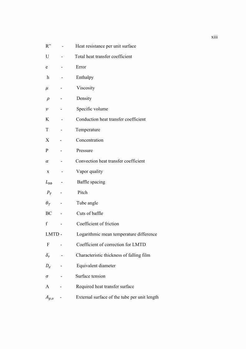
xiii
R” - Heat resistance per unit surface
U - Total heat transfer coefficient
e - Error
h - Enthalpy
� - Viscosity
- Density
- Specific volume
K - Conduction heat transfer coefficient
T - Temperature
X - Concentration
P - Pressure
� - Convection heat transfer coefficient
x - Vapor quality
� - Baffle spacing
�� - Pitch
�� - Tube angle
BC - Cuts of baffle
f - Coefficient of friction
LMTD - Logarithmic mean temperature difference
F - Coefficient of correction for LMTD
�� - Characteristic thickness of falling film
�� - Equivalent diameter
� - Surface tension
A - Required heat transfer surface
��,� - External surface of the tube per unit length

xiv
��,� - Inner surface of the tube per unit length
���� - Effective length
1
CHAPTER 1
INTRODUCTION
1.1 History of refrigeration
Before 19th century AD refrigeration was just limited to transfer ice from cold
region to warm areas and keep it in specific boxes for using in hot seasons. In 1834
the first manually refrigeration machine in England caused a change in the
refrigeration industry. Before that in 1824 a series of tests done by Michele faraday
to convert some stabilized gas to the liquid. Although faraday could not use those
experiences for cooling, they became a prelude for the future. In 1851 an American
made a machine which produced ice it was using air as refrigerant. In 1859 an
absorption cycle was used by Ferdinand Carre with ammonia as refrigerant and water
as absorbent. Americans used this system for the first time to made absorption
chillers. In 1860 the first ether sulfuric machine made for refrigeration in beverage
industry in Australia. Later on in 1880 the first company for making ice established.
In 1890 compression refrigeration and absorption refrigeration became really
common but they were very bulky and expensive. One of the reasons that mechanical
refrigeration did not develop in the early decades was the usage of steam to spin a
compressor. By inventing electric motors and improvement in non dangerous
refrigerant, refrigeration industry reached its peak. small Air refrigerators and

2
household freezers produced widely and still continue to evolve and progress. The
operation of absorption chillers is based on Michael faraday experiment in 1842. In
that time scientist thought that ammonia is just exists as vapor, faraday did some
experiment to make it liquid. During the experiment he understood that ammonia
absorb the ambient heat when it convert from vapor to liquid and cause refrigeration.
That was the start point for appearance of absorption refrigeration systems. For the
first time absorption refrigeration systems was invented by Ferdinand Carre in 1860.
1.2 Why absorption chillers
Refrigeration and cooling cycles are mostly based on mechanical vapor
compression. In Warm climate countries, where cooling needs a large amount of
electricity, the usage of alternative technologies could be preferred. Absorption
chillers get their energy from sun or waste heat of other devices such as turbine in
power plant to drive Cooling system. Absorption chillers are a good alternative for
compressor chillers when electricity is unavailable, expensive or unreliable, or where
compressor noise is a problem. Since absorption chillers have a lot of advantages in
comparison
with mechanical chillers, usage of them is more economical and
environmental friendly. Absorption chillers are a good choice these days, hence
optimizing them will be an important issue. In this study it is tried to design the
generator and condenser and optimizing generator in a single effect LiBr/H2o indirect
fired absorption chillers. The waste energy from a gas power plant is used to drive
the generator. This heat will be obtained from the hot gas which is expelling to
ambient from turbine in power plant. Let’s know more about absorption chillers.

3
1.3 What is Absorption Refrigeration
These kinds of chillers use heat instead of mechanical energy to provide
cooling. A thermal compressor includes an absorber, a generator, a pump and a
throttling device, and replace mechanical vapor compressor. In these chiller the
vapor that comes from evaporator absorb by solution in absorber, mix with solution
and become liquid, then the solution pump to generator. In generator solution will be
heated by the waste heat or solar source or other sources then re-vaporize so the
refrigerant separate from absorbent then this vapor will go to the condenser and the
refrigerant-depleted solution will go back to the absorber through a throttling device.
Two solution mostly use in absorption chillers, water/lithium bromide and
ammonia/water. The first solution mostly use for air conditioning and the second one
use for refrigeration purposes. Pair of lithium bromide /water is more common due to
high volatility, stability and relatively high latent heat, high safety factor of water and
the higher COP in the cycle. Since water freezes at zero degree centigrade this
solution cannot be used in low temperatures hence the temperature of exited water
from chiller cannot be less 7 degree of centigrade but this temperature is enough for
air conditioning. For obtaining lower temperature it is needed to use NH3/H2o as the
solution in the cycle.
Cop is coefficient of performance (chiller load/heat input). High amount of
cop indicate the optimized consumption of energy.
Crystallization: in the solution, LiBr is liquid in the common density but if it
is over concentrated in generator by giving heat to it, the inside crystals will increase
in size and block the way of solution. This is called crystallization.
4
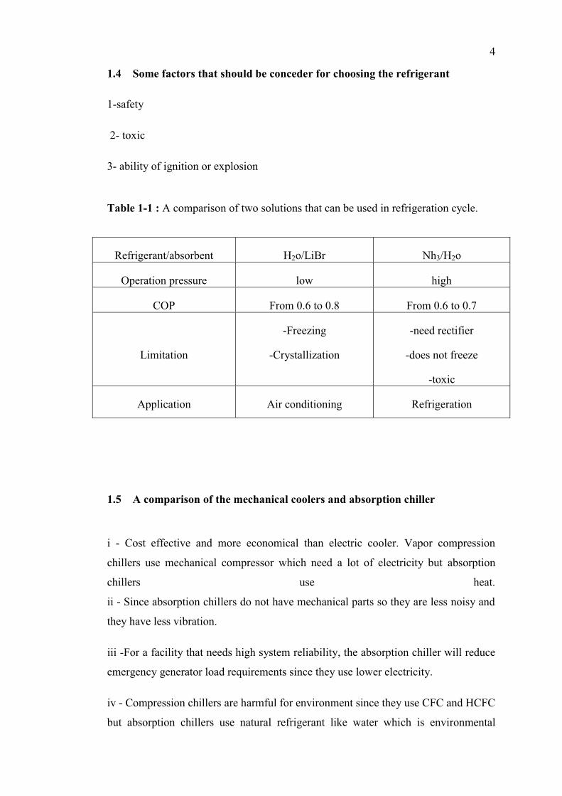
1.4 Some factors that should be conceder for choosing the refrigerant
1-safety
2- toxic
3- ability of ignition or explosion
Table 1-1 : A comparison of two solutions that can be used in refrigeration cycle.
Refrigerant/absorbent H2o/LiBr Nh3/H2o
Operation pressure low high
COP From 0.6 to 0.8 From 0.6 to 0.7
Limitation
-Freezing
-Crystallization
-need rectifier
-does not freeze
-toxic
Application Air conditioning Refrigeration
1.5 A comparison of the mechanical coolers and absorption chiller
i - Cost effective and more economical than electric cooler. Vapor compression
chillers use mechanical compressor which need a lot of electricity but absorption
chillers use heat.
ii - Since absorption chillers do not have mechanical parts so they are less noisy and
they have less vibration.
iii -For a facility that needs high system reliability, the absorption chiller will reduce
emergency generator load requirements since they use lower electricity.
iv - Compression chillers are harmful for environment since they use CFC and HCFC
but absorption chillers use natural refrigerant like water which is environmental

5
friendly.
v - Absorption chillers have lower coefficient of performance (COP = chiller load /
heat input)
1.6 Absorption chiller disadvantages
Although absorption chillers are really good but they have some
disadvantages. Their COP is less than compression chillers since they use water
which is less efficient refrigerant in comparison with fluorocarbon based refrigerants
that use in compression chillers. They have higher first cost than compression
chillers and they are larger than electric chiller with the same capacity.
Using absorption chillers for cooling the site is good when at least one of the
fallowing conditions applies
i -A combined heat and power CHP) unit exists, and you cannot use all the available
heat, or considering a new CHP plant.
ii - you have a large amount of Waste heat.
iii -When a low cost fuel source is available.
iv - When the efficiency of boiler is low due to a poor load.
v - when electrical load of the site is limit and expensive to upgrade.
vi - When your site needs more cooling, but it is expensive to overcome the electrical
and there is an adequate heat supply.
-In short, absorption chillers use when a free or low-cost heat source is available.
6
1.7 Absorption Chiller Refrigeration Cycle
A basic absorption cycle consists of two fluids, refrigerant and absorbent.
Commonly water is used as refrigerant and lithium bromide used as absorbent. These
fluids are separated and mixed in absorption cycle. In this cycle the low pressure
vapor (refrigerant) that comes from evaporator, absorbed by absorbent and release a
large amount of heat in absorber then this solution is pumped to the high operating
pressure generator and use lower electricity in comparison with mechanical chillers.
In generator heat is added to the solution and it is caused that refrigerant desorbs
from absorbent and vaporize.
The heat in generator is obtained from hot water, hot gases, steam or gas
burner. The high pressure refrigerant vapor then goes to the condenser, reject some
heat and convert to high pressure liquid. After that this liquid passes through an
expansion valve and looses the pressure to enter the evaporator. In the evaporator
this liquid refrigerant absorbs heat to become vapor and cause a useful cooling. The
remained liquid absorbent in generator pass through an expansion valve to reduce the
pressure then go to the absorber. In the way back, it gives some heat to the solution
which is comes from absorber in an heat exchanger. This will increase the efficiency.
This cycle will be repeated.
1.8 "Indirect fire" and "direct fire" absorption chillers
Indirect fire chillers use hot gases, hot water or steam as an input. These
inputs can come from a turbine, boiler or engine generator or other devices that have
waste energy. These chillers are good for CHP (combine heat and power) system for
buildings. The rejected heat from electric generator is used as an input for chiller
hence by using the waste energy the operating efficiency will increase.

7
Direct fired systems have natural gas burners so the rejected heat from these
chillers can provide the hot water or can be used to regenerate desiccant
dehumidifiers.
1.9 Commercially division of absorption chillers
There are two kinds of absorption chillers, single effect and multiple effects.
In single effect chillers all the heat that produced by absorbing the refrigerant in
absorber release to the environment but in multiple effect chillers this heat is also
used to provide refrigerant vapor in generator. More vapor generated from per unit of
input heat cause higher cooling capacity and better efficiency.
8
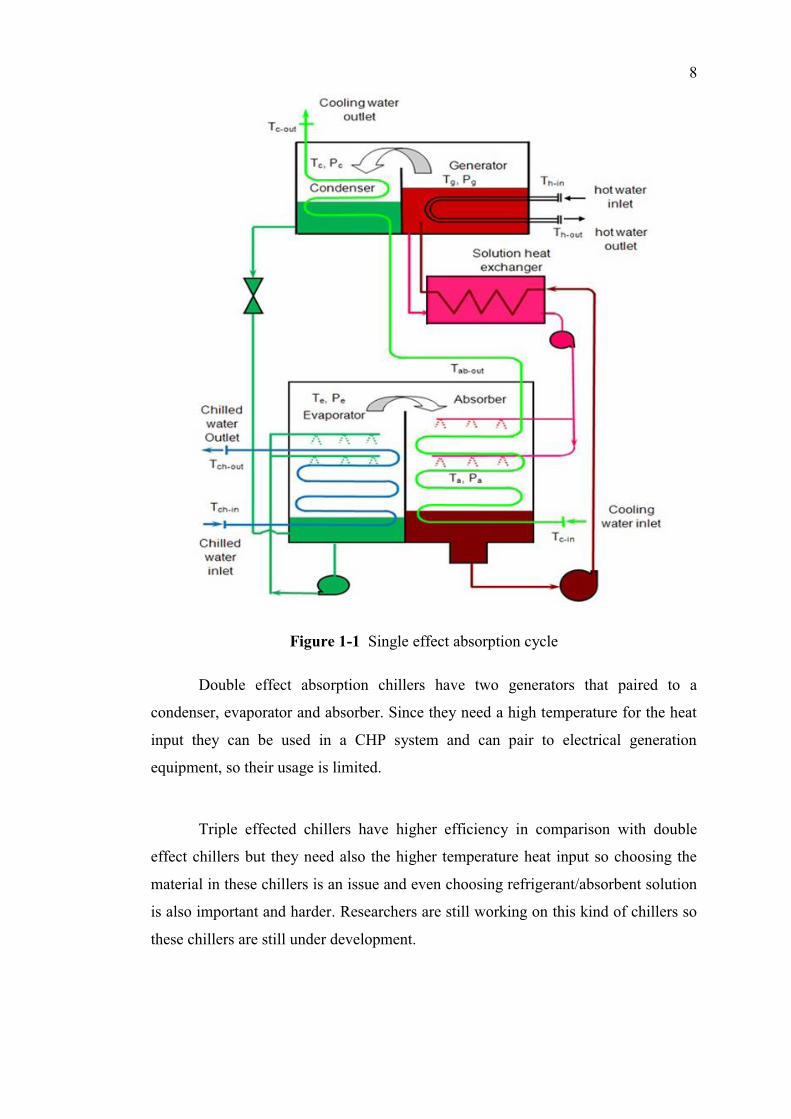
Figure 1-1 Single effect absorption cycle
Double effect absorption chillers have two generators that paired to a
condenser, evaporator and absorber. Since they need a high temperature for the heat
input they can be used in a CHP system and can pair to electrical generation
equipment, so their usage is limited.
Triple effected chillers have higher efficiency in comparison with double
effect chillers but they need also the higher temperature heat input so choosing the
material in these chillers is an issue and even choosing refrigerant/absorbent solution
is also important and harder. Researchers are still working on this kind of chillers so
these chillers are still under development.
9
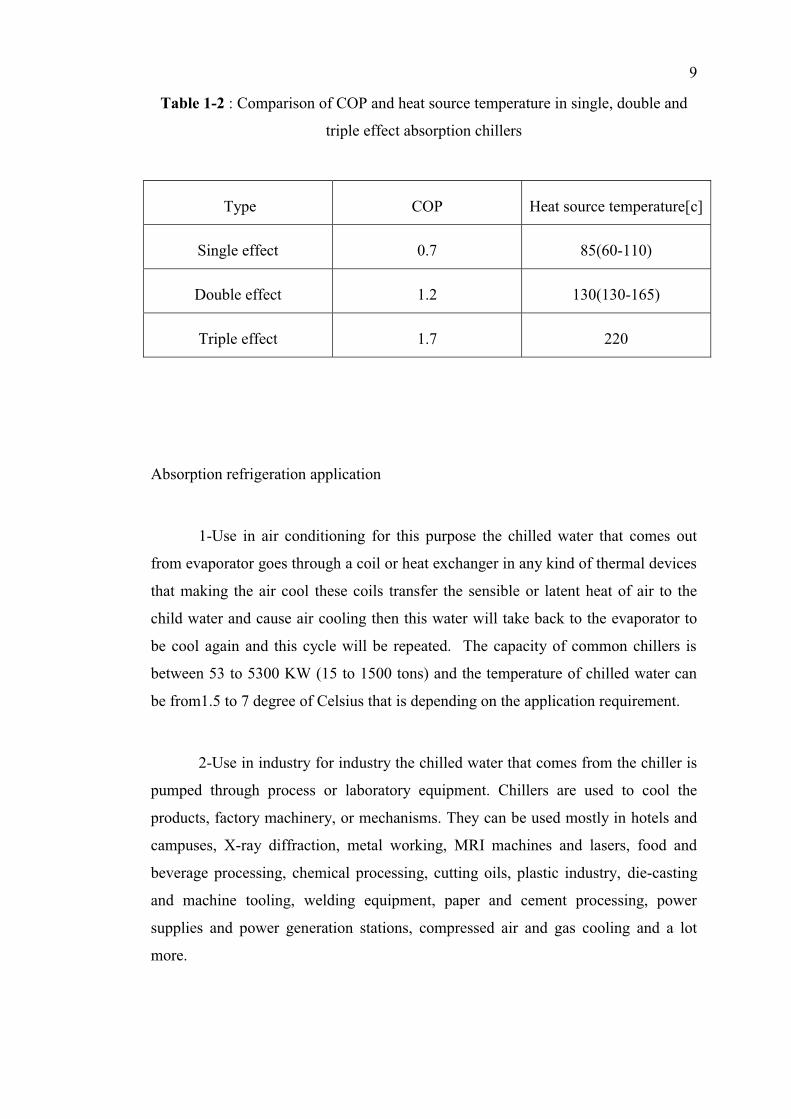
Table 1-2 : Comparison of COP and heat source temperature in single, double and
triple effect absorption chillers
Type COP Heat source temperature[c]
Single effect 0.7 85(60-110)
Double effect 1.2 130(130-165)
Triple effect 1.7 220
Absorption refrigeration application
1-Use in air conditioning for this purpose the chilled water that comes out
from evaporator goes through a coil or heat exchanger in any kind of thermal devices
that making the air cool these coils transfer the sensible or latent heat of air to the
child water and cause air cooling then this water will take back to the evaporator to
be cool again and this cycle will be repeated. The capacity of common chillers is
between 53 to 5300 KW (15 to 1500 tons) and the temperature of chilled water can
be from1.5 to 7 degree of Celsius that is depending on the application requirement.
2-Use in industry for industry the chilled water that comes from the chiller is
pumped through process or laboratory equipment. Chillers are used to cool the
products, factory machinery, or mechanisms. They can be used mostly in hotels and
campuses, X-ray diffraction, metal working, MRI machines and lasers, food and
beverage processing, chemical processing, cutting oils, plastic industry, die-casting
and machine tooling, welding equipment, paper and cement processing, power
supplies and power generation stations, compressed air and gas cooling and a lot
more.
10
1.10 Different type of water chillers
Water chillers can be air cooled, water cooled or evaporatively cooled. Water
cooled chillers are mostly use for indoor installation and they use an outdoor cooling
tower to reject the heat to the environment. Usage of cooling tower in these chillers
increase their thermodynamic effectiveness in comparison with air cooled chillers.
The reason is that heat rejection is happened near wet bulb temperature and the
amount of this heat is higher than the heat which is rejected near dry bulb
temperature.
Evaporatively cooled and air cooled chiller typically used for outside
installation. Air cooled chillers are cooled directly by the environment air which is
mechanically circulated around coils in condenser. Evaporatively cooled chillers are
the same as air cooled chillers; just in this case a mist of water is used over the
condenser coil which is helped better cooling so they are more efficient than air
cooled chillers. For these two kinds there is no need of cooling tower.
Efficiency: water cooled chillers > evaporatively cooled chillers > air cooled chillers
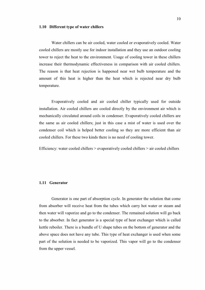
1.11 Generator
Generator is one part of absorption cycle. In generator the solution that come
from absorber will receive heat from the tubes which carry hot water or steam and
then water will vaporize and go to the condenser. The remained solution will go back
to the absorber. In fact generator is a special type of heat exchanger which is called
kettle reboiler. There is a bundle of U shape tubes on the bottom of generator and the
above space does not have any tube. This type of heat exchanger is used when some
part of the solution is needed to be vaporized. This vapor will go to the condenser
from the upper vessel.
11
Figure 1-2 A two-dimensional model of the kettle reboiler shell side thermal-
hydraulics.
There are different types of heat exchangers. One of them is shell and tube
heat exchanger. Since generator that is used in absorption cycle is one of these
exchangers it is worth to know more about this type of heat exchangers.
1.12 Condenser
In systems involving heat transfer, a condenser is a device or unit used to
condense a substance from its gaseous to its liquid state, typically by cooling it. In so
doing, the latent heat is given up by the substance, and will transfer to the condenser
coolant.

12
Figure 1-3 Diagram of a typical water-cooled surface condenser
1.13 Shell and tube heat exchangers
Shell and tube heat exchangers consist of a series of tubes. One set of these
tubes contains the fluid that must be either heated or cooled. The second fluid runs
over the tubes that are being heated or cooled so that it can either provide the heat or
absorb the heat required. A set of tubes is called the tube bundle and can be made up
of several types of tubes: plain, longitudinally finned, etc. Shell and tube heat
exchangers are typically used for high-pressure applications (with pressures greater
than 30 bar and temperatures greater than 260°C). This is because the shell and tube
heat exchangers are robust due to their shape.
There are several thermal design features that are to be taken into account
when designing the tubes in the shell and tube heat exchangers. These include:
13
-Tube diameter
Using a small tube diameter makes the heat exchanger both economical and
compact. However, it is more likely for the heat exchanger to foul up faster and the
small size makes mechanical cleaning of the fouling difficult. To prevail over the
fouling and cleaning problems, larger tube diameters can be used. Thus to determine
the tube diameter, the available space, cost and the fouling nature of the fluids must
be considered.
-Tube thickness
The thickness of the wall of the tubes is usually determined to ensure:
i- There is enough room for corrosion
ii- That flow-induced vibration has resistance
iii- Axial strength
iv- Availability of spare parts
v- Hoop strength (to withstand internal tube pressure)
vi- Buckling strength (to withstand overpressure in the shell)
-Tube length
heat exchangers are usually cheaper when they have a smaller shell diameter
and a long tube length. Thus, typically there is an aim to make the heat exchanger as
long as physically possible whilst not exceeding production capabilities. However,
there are many limitations for this, including the space available at the site where it is
going to be used and the need to ensure that there are tubes available in lengths that
are twice the required length (so that the tubes can be withdrawn and replaced). Also,
it has to be remembered that long, thin tubes are difficult to take out and replace.
14
-Tube pitch
when designing the tubes, it is practical to ensure that the tube pitch (i.e., the
centre-centre distance of adjoining tubes) is not less than 1.25 times the tubes'
outside diameter. A larger tube pitch leads to a larger overall shell diameter which
leads to a more expensive heat exchanger.
-Tube corrugation
This type of tubes, mainly used for the inner tubes, increases the turbulence
of the fluids and the effect is very important in the heat transfer giving a better
performance.
-Tube Layout
refers to how tubes are positioned within the shell. There are four main types
of tube layout, which are, triangular (30°), rotated triangular (60°), square (90°) and
rotated square (45°). The triangular patterns are employed to give greater heat
transfer as they force the fluid to flow in a more turbulent fashion around the piping.
Square patterns are employed where high fouling is experienced and cleaning is
more regular.
-Baffle Design
baffles are used in shell and tube heat exchangers to direct fluid across the
tube bundle. They run perpendicularly to the shell and hold the bundle, preventing
the tubes from sagging over a long length. They can also prevent the tubes from
vibrating. The most common type of baffle is the segmental baffle. The semicircular
segmental baffles are oriented at 180 degrees to the adjacent baffles forcing the fluid
to flow upward and downwards between the tube bundles. Baffle spacing is of large
thermodynamic concern when designing shell and tube heat exchangers. Baffles
must be spaced with consideration for the conversion of pressure drop and heat
transfer. For thermo economic optimization
15
It is suggested that the baffles be spaced no closer than 20% of the shell’s
inner diameter. Having baffles spaced too closely causes a greater pressure drop
because of flow redirection. Consequently having the baffles spaced too far apart
means that there may be cooler spots in the corners between baffles. It is also
important to ensure the baffles are spaced close enough that the tubes do not sag. The
other main type of baffle is the disc and donut baffle which consists of two
concentric baffles, the outer wider baffle looks like a donut, whilst the inner baffle is
shaped as a disk. This type of baffle forces the fluid to pass around each side of the
disk then through the donut baffle generating a different type of fluid flow.
1.14 Combined Heat and Power (CHP)
CHP plays an important part in meeting energy requirements and reducing
the environmental impact of power generation, providing numerous benefits to both
the user and the environment. A CHP scheme will dramatically cut costs because it
operates at much higher efficiencies than other forms of power generation. CHP, also
known as cogeneration, is a simple concept which involves a cost-efficient means of
generating both electrical and thermal energy from the same fuel source. The
electricity generated by the gas turbine generator can be used as an “island” solution
for stand-alone power supply in manufacturing plants and industrial facilities.
However, the gas turbine exhaust is packed with thermal energy which, in a CHP
solution, can be recovered in a heat exchanger to generate either steam or hot water
For further application. Municipal utilities can use the steam for district
heating, and industrial users benefit from using it in production processes, e.g. for
heating or drying. Alternatively steam can be used in absorption chillers to cool
industrial processes or warehousing facilities. A CHP system is one of the most
efficient ways of converting fuel into useful energy. You can expect a conversion
efficiency of up to 95% from a well designed scheme
16
All thermal power plants produce waste heat energy as a byproduct of the
useful electrical energy produced. The amount of waste heat energy equals or
exceeds the amount of electrical energy produced. Gas-fired power plants can
achieve 50% conversion efficiency while coal and oil plants achieve around 30-49%.
1.15 Problem statement
i) absorption chillers known to have low coefficient of performance (COP)
In comparison with compression chillers these kinds of absorbers have lower COP so
trying to increase the COP is one of the issues that should be work on it.
ii) The big size of absorption chillers.
Since absorption chillers are big, installing them everywhere is not possible; by
minimizing the size of absorption chillers this limitation will be eliminated.
iii) by increasing cop, cost will increase.
The cost of chiller is another factor that should be under consideration. The bigger
size the chillers have, the higher cost they have. For increasing COP the surface of
heat transfer in different component of chillers usually increase. The main issue is to
bring up COP while the cost reduces.
17
1.16 Objectives
i. designing generator and condenser
ii. optimizing design of generator
iii. optimizing design of condenser
iv. compare the performance of optimized generator and condenser with the
existing one.
1.17 scopes
i- litereture review on previous works for designing and optimizing heat exchangers.
ii- set the thermodynamic and physical properties based on exciting model for the
cycle.
iii- study and understand about genetic algorithm for optimization.