Embed Size (px)
Citation preview
SUBJECT:
EFFECTIVIN:
REASON:
COMPLIANCE:
CLASS II
SERVICE INSTRUCTIONS No. 1 175
ATA Code 77-00
ENGINE INDICATING - MODIFICATION AND CALIBRATION OF AIRCRAFT INSTRUMENT AND DEVELOPMENT INCORPORATED ENGINE INSTRUMENT CLUSTERS
NOTE
These Service Instructions supersede and cancel BEECHCRAFT Service lnstructions No. 1065.
BEECHCRAFT Duchess 76, serials ME-1 through ME-349; Skipper 77, serials WA-1 through WA-101 and WA-104; and any other Duchess 76 and Skipper 77 airplanes which may have installed a replacement engine instrument cluster manufactured by Aircraft Instrument and Development Incorporated with any of the following serial numbers:
MODEL ENGINE INSTRUMENT CLUSTER PART NUMBER
105-38901 1-5 (14 volt system)
or 1 05-38901 1 -31 (28 volt system)
NOTE
ENGINE INSTRUMENT CLUSTER SERIAL NUMBER
1 through 419, 1000 through 1068 and 1088 through 1091
1 through 279
These Service lnstructions affect only engine instrument clusters manufactured by Aircraft Instrument and Development Incorporated. Other engine instrument clusters are not affected.
To provide improved reliability of the engine instrument cluster.
At the owner's discretion, however, Beech Aircraft Corporation recommends that this modification be accomplished and the engine instrument cluster be recalibrated the next time the engine instrument cluster is removed from the airplane for any type of maintenance.
No BECP
301 11
Beech Alrcraft Corporat~on Issues servtce lnformatton for the benef~t of owners and flxed base operators In the form of three classes of Service lnstructlons CLASS I (Red Border) are changes tnspectlons, and rnod~ftcattons that could affect safety The factory cons~ders cornpl~ance mandatory CLASS II (Green Border) covers changes modlflcat~ons, Improvements or lnspectlons the factory feels will beneftt the owner and although h~ghly recommended, they are not cons~dered mandatory cornpl~ance, t~nless spec~fted at the tlrne of Issuance
8 Class I and II are malted to . , N v (a) BEECHCRAFT Aero or Avtat~on Centers and Intervat~onal 3 D~str~butors and Dealers 8 (b) Owners of record on the FAA Reg~stration lfst a i d the
BEECHCRAFT Internattonal Owner Notification Service List. (c) Those havlng a publications subscript~on.
CLASS Ill (No Border) covers changes whlch are opttonal, matntenance a~ds. product Improvement k~ts and miscellaneous servlce lnforrnat~on Cornpltance 1s at the owner or operators prerogarlve Coptes of Class Ill are dlstrtbuted per a and c above lnformat~on on Owner Not~ftcatton Service or Subscr~ptlons can be obtalned through any BEECHCRAFT Aero or Av~atlon Center, lnternat~onal Dlstrlbutor and Dealer or the Factory As Service lnstruct~ons are ~ssued. temporary notatlon In the Index should be made until the tndex 1s revlsed Warranty will be allowed only when spec~flcally deflned In the Servlce lnslructlons and In accordance wlth Beech Warranty Poltcy 43 M e m b e r 01 G A M A
Generat M.nvfaclurcr% Avw#non Anooot8on
Service lnstructions No. 1175
APPROVAL: FAA Approved.
MANPOWER: The following information is for planning purposes only:
Estimated man-hours: 4 hours. Suggested number of men: 1 man.
MATERIAL: The following parts required for this modification may be ordered through BEECHCRAFT Aero or Aviation Centers and International Distributors and Dealers.
WARRANTY:
PART NUMBER DESCRIPTION
Mylar Strip
QUANTITY PER AIRPLANE
12 (Duchess 76) 6 (Skipper 77)
'476 Black Vinyl Tape As Required
*PIN of Minnesota Mining and Manufacturing Company, 3M Center, St. Paul, Minnesota 55101. May be obtained from local sources.
The value of the parts required to incorporate these Service lnstructions on one airplane is to be advised. Prices, when issued, will be subject to change without notice.
BEECHCRAFT Warranty on a new airplane is 180 days from delivery or 180 days from the date noted on the Owner Warranty Card. Warranty credit for parts and labor to the extent noted under MATERIAL and MANPOWER will be allowed on BEECHCRAFTS within warranty at the time these Service lnstructions are released.
All warranty reimbursements are handled through franchised BEECHCRAFT Aero or Aviation Centers and International Distributors and Dealers. Owners and operators should arrange with these outlets to perform the work and have them submit the standard Beech Aircraft Corporation warranty claim form through BEECHCRAFT Parts and Equipment Marketing Wholesalers or International Distributors.
SPECIAL TOOLS:
WEIGHT AND BALANCE:
REFERENCES:
None.
None.
BEECHCRAFT Duchess 76 Maintenance Manual, PIN 105-590000-7 or subsequent, Chapter 77-00; BEECHCRAFT Skipper 77 Maintenance Manual, PIN 108-590000-7 or subsequent, Chapter 77-00; BEECHCRAFT Duchess 76 Wiring Diagram Manual (14 Volt), PIN 105-590000-158 or subsequent, Chapter 77-20; BEECHCRAFT Duchess 76 Wiring Diagram Manual (28 Volt), PIN 105-590000-21 or subsequent, Chapter 77-20; BEECHCRAFT Skipper 77 Wiring Diagram Manual, PIN 108-590000-158 or subsequent, Chapter 91 -1 5.
PUBLICATIONS AFFECTED: It is recommended that a note to "See Service Instructions No. 1175" be made in the following:
BEECHCRAFT Duchess 76 Maintenance Manual, PIN 105-590000-7 or subsequent, Chapter 77-00; BEECHCRAFT Skipper 77 Maintenance Manual, PIN 108-590000-7 or subsequent, Chapter 77-00; BEECHCRAFT Duchess 76 Parts Catalog, PIN 105-590000-9B or subsequent, Chapter 39-10; BEECHCRAFT Skipper 77 Parts Catalog, PIN 108-590000-9 or subsequent, Chapter 39-10.
Service Instructions No. 1175
ACCOMPLISHMENT These Service lnstructions may be accomplished as follows: INSTRUCTIONS:
1. Turn off andlor disconnect all electrical power and disconnect the battery.
2. Remove the instrument panel glareshield. 3. Inspect the engine instrument cluster and
determine if it was manufactured by Aircraft Instrument and Development Incorporated.
4. If the engine instrument cluster was not manufactured by Aircraft lnstrument and Development Incorporated, reinstall the glareshield and reconnect the battery. No further action i s necessary.
5. I f the engine instrument c luster was manufactured by Aircraft lnstrument and Development lncorporated but does not have one of the serial numbers listed under EFFECTIVITY, reinstall the glare shield and reconnect the battery. No further action is necessary.
6. If the engine instrument c luster w a s manufactured by Aircraft lnstrument and Development lncorporated and does have one of the serial numbers listed under EFFECTIVITY, continue with step 7.
7. Refer to the Maintenance Manual, Chapter 77-00 and remove the engine instrument cluster.
NOTE
Steps 8 through 15 must be accomplished by an appropriately rated instrument repair facility.
8. Refer to the wiring diagrams in Figures 4, 5 and 6 and repair the engine instrument cluster i f required.
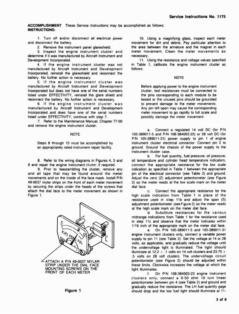
9. Prior to reassembling the cluster, remove any and all tape that may be found around the meter movements and on the inside of the face mask. Install PIN 49-0037 mylar strips on the front of each meter movement by securing the strips under the heads of the screws that attach the dial face to the meter movement as shown in Figure 1.
L ~ l T ~ ~ ~ A PIN 49-0037 MYLAR STRIP UNDER THE DIAL FACE MOUNTING SCREWS ON THE FRONT OF EACH METER
Figure 1
10. Using a magnifying glass, inspect each meter movement for dirt and debris. Pay particular attention to the area between the armature and the magnet in each meter movement. Clean the meter movements as necessary.
11. Using the resistance and voltage values specified in Table 1, calibrate the engine instrument cluster as follows:
NOTE
Before applying power to the engine instrument cluster, test resistances must be connected to the pins corresponding to each module to be tested or the unused pins should be grounded to prevent damage to the meter movements. Any pin left open may cause the corresponding meter movement to go rapidly to full scale and possibly damage the meter movement.
a. Connect a regulated 14 volt DC (for PIN 105-38901 1-5 and PIN 108-384003-23) or 28 volt DC (for PIN 105-38901 1-31) power supply to pin 1 of engine instrument cluster electrical connector. Connect pin 2 to ground. Ground the chassis of the power supply to the instrument cluster case.
b. For fuel quantity, fuel pressure, oil pressure, oil temperature and cylinder head temperature indicators, connect the appropriate resistance for the low scale indication as specified in Table 1 between the appropriate pin of the electrical connector (see Table 2) and ground. Adjust the zero (Z) adjustment potentiometer (see Figure 2) so the meter reads at the low scale mark on the meter dial face.
c. Connect the appropriate resistance for the high scale indication from Table 1 in place of the resistance used in step 1 1 b and adjust the span (S) adjustment potentiometer (see Figure 2) so the meter reads at the high scale mark on the meter dial face.
d. Substitute resistances for the various midrange indications from Table 1 for the resistance used in step llc and observe that the meter indicates within 1/16 inch of the appropriate mark on the meter dia! face.
e. On PIN 105-38901 1-5 and 105-38901 1-31 engine instrument clusters only, connect a variable power supply to pin 1 1 (see Table 2). Set the voltage at 14 or 28 volts, as applicable, and gradually reduce the voltage until the undervoltage light is illuminated. The light should illuminate at 12.2 + .1 volts on 14 volt clusters and 23.75 ?
.5 volts on 28 volt clusters. The undervoltage circuit potentiometer (see Figure 2) should be adjusted within these limits. Clockwise increases the voltage at which the light illuminates.
f. On PIN 108-384003-23 engine instrument clusters only, connect a 0-50 ohm 10 turn linear potentiometer between pin 4 (see Table 2) and ground and gradually reduce the resistance. The LH fuel quantity gage should drop and the low fuel light should illuminate at 1 1 -

Service Instructions No. 11 75
/ RH FUEL QUANTITY
DUCHESS 76 INSTRUMENT CLUSTER ADJUSTMENT POINTS (105-38901 1-5 & 105-38901 1-31)
DUCHESS 76 INSTRUMENT CLUSTER UNDER VOLTAGE CIRCUIT ADJUSTMENTS (1 05-38901 1-5 & 105-38901 1-31)
ZERO ADJUSTMENT
SPAN ADJUSTMENT SPAN ADJUSTMENT
ND SKIPPER 77 FUEL PRESSURE, OIL PRESSURE, OIL TEMPERATURE AND DUCHESS 76 LOADMETER CYLINDER HEAD TEMPERATURE GAGES OR SKIPPER 77 AMMETER
FUEL PRESSURE ZERO ADJUSTMENT
?
RH FUEL QUANTITY SPAN ADJUSTMENT
RH FUEL QUANTITY ZERO ADJUSTMENT
LH FUEL QUANTITY SPAN ADJUSTMENT
LH FUEL QUANTITY ZERO ADJUSTMENT
SKIPPER 77 INSTRUMENT CLUSTER ADJUSTMENT POINTS (1 08-384003-23)
r LOW FUEL POTENTIOMETER
SKIPPER 77 LOW FUEL LIGHT ADJUSTMENTS (1 08-384003-23)
Figure 2 Engine Instrument Cluster Adjustment Points

Service Instructions No. 1175
CHECKTO ASSURETHATTHE PIN 476 BLACK VINYL TAPE IS INTACT ALONG THE TOP EDGE OF THE INSIDE OF THE ENGINE INSTRUMENT CLUSTER
ENGINE INSTRUMENT CLUSTER CASE
Figure 3 Duchess 76 Engine lnstrument Cluster Case
50 MICRO AMP W 1 MA SHUNT I PIN 105-38901 1-29
RIGHT SIDE SAME RLP LENS EXCEPT OMIT 6 PM BEP SOCKET 7219 LAMPS
WIRED
-14 VDC
+14 VDC
CASE
Figure 4 Duchess 76 Engine Instrument Cluster Wiring Diagram
(1 05-38901 1-5 14 Volt)

Service Instructions No. 1175
50 MICRO AMP W 1 MA SHUNT
I PIN 105-38901 1-29
- OIL PRESS A@
W ERN
W RED
- 28 VDC
+ 28 VDC
Figure 5 Duchess 76 Engine Instrument Cluster Wiring Diagram
(1 05-38901 1-31 28 Volt)
12 ohms. Resistance must be reduced very gradually because the low fuel light has a 3 second delay before it illuminates after the threshold has been reached. Adjust the low fuel potentiometer (see Figure 2) to these limits. Connect the 0-50 ohm potentiometer between pin 8 (see Table 2) and ground and repeat the procedure for the RH fuel quantity gage. Check operation of the low fuel quantity light test switch in both the left and right positions.
g. Disconnect the power supply and ground from pins 1 and 2 on the engine instrument cluster electrical connector.
h. On PIN 105-38901 1-5 and PIN 105-38901 1 - 31 engine instrument clusters, apply voltages of 0, 25 and 50 millivolts to pins 9 + and 10- (see Table 2) and observe that the loadmeter indicates 0, 50% and 100% respectively. Meter indications should be within 1 11 6 inch of the appropriate mark on the meter dial face. Adjust the load meter span adjustment potentiometer (see Figure 2) as required to obtain the proper readings.
i. On PIN 108-384003-23 engine instrument clusters, apply voltages of 0, + 50 and - 50 millivolts to
pins 9+ and 10- (see Table 2) and observe that the ammeter indications are 0, CHG and DIS respectively. Meter indications should be within 1/16 inch of the appropriate mark on the meter dial face. Adjust the ammeter span adjustment potentiometer (see Figure 2) as required to obtain the proper readings.
12. Reassemble the engine instrument cluster into the engine instrument cluster case.
NOTE
On PIN 105-38901 1-5 and 105-38901 1-31 engine instrument clusters, check to assure the tape is intact along the top edge of the inside of the engine instrument cluster case (see Figure 3). If necessary, replace the tape with PIN 476 black vinyl tape. This tape reduces the possibility of the fuel quantity gages shorting against the engine instrument cluster case.
8uvbo lnmucmm No. 1175
13. Check the operation of the engine instrument cluster at a sufficient number of points as specified in step 11 to assure that reassembly has not caused any mechanical interference and all gages operate properly.
14. Seal the outside edge between the engine instrument cluster and the engine instrument cluster case with PIN 476 black vinyl tape.
15. Seal all adjustment holes in the engine instrument cluster case with PIN 476 black vinyl tape.
16. Refer to the Maintenance Manual, Chapter 77-00 and adjust the fuel quantity and fuel pressure gages as
required to match the airplane system. Reseal any adjustment holes as required with PIN 476 black vinyl tape.
17. Refer to the Maintenance Manual, Chapter 77-00 and reinstall the engine instrument cluster in the instrument panel.
18. Reinstall the glare shield and any other equipment or panels which may have been removed to accomplish these Service Instructions.
19. Ground run the airplane and check the engine instrument cluster for proper operation.
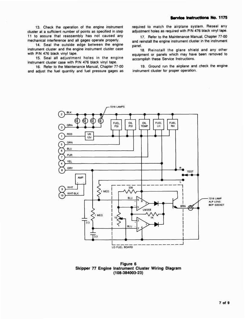
7219 U M P
BEP SOCKET I
Figure 6 Skipper 77 Engine Instrument Cluster Wiring Diagram
(1 08-384003-23)
Sewice Instructions No. 1175
MODEL 76 FUEL QTY
QTY
E 114
112 314 F
7
76 AND 77 FUEL PRESSURE
J
76 AND 77 OIL TEMPERATURE
MODEL 77 FUEL QTY
QTY I OHMS I TOL OHMS OHMS
6 25
38 48 61
TOL OHMS
-t 1.9
t 1.9 2 2.8
PSI
.5 8
12
MODEL 76 LOADMETER
TOL
t 1/16 IN -c 1.2 OHM
t 1.5 OHM t 1.5 OHM
-c 1.2 OHM
OHMS
12.9 54.5 76.8
TOL OHMS
t 1.4 r 1.4
t 1.4 t 1.4
OF
60 120 200 245
O/o
0 50
100 i
76 AND 77 OIL PRESSURE
OHMS
95.74 107.96 126.00
137.00
MODEL 76 CYL HD TEMP
VOLTAGE
0 MV 25 MV 50 MV
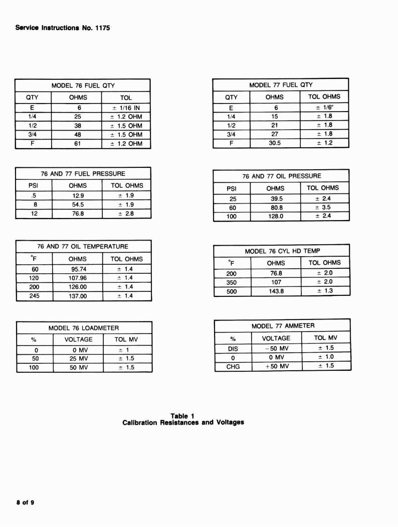
Table 1 Calibration Resistances and Voltages
TOL OHMS
+ 2.4 t 3.5 2 2.4
PSI
25 60
100
MODEL 77 AMMETER
TOL MV
t 1 t 1.5
-t 1.5
OHMS
39.5 80.8
128.0
TOL OHMS
t 2.0 - + 2.0 t 1.3
OF
200 350 500
OHMS
76.8 107
143.8
TOL MV
t 1.5 -t 1.0 t 1.5
O/o
DIS 0
CHG
VOLTAGE
-50 MV 0 MV
+50 MV
Service Instructions No. 1175
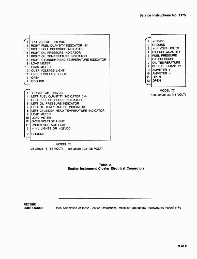
+ 14 VDC OR + 28 VDC RIGHT FUEL QUANTITY INDICATOR (IN) RIGHT FUEL PRESSURE INDICATOR RIGHT OIL PRESSURE INDICATOR RIGHT OIL TEMPERATURE INDICATOR RIGHT CYLINDER HEAD TEMPERATURE INDICATOR LOAD METER LOAD METER OVER VOLTAGE LIGHT UNDER VOLTAGE LIGHT OPEN GROUND
+ 14VDC OR + 28VDC LEFT FUEL QUANTITY INDICATOR (IN) LEFT FUEL PRESSURE INDICATOR LEFT OIL PRESSURE INDICATOR LEFT OIL TEMPERATURE INDICATOR LEFT CYLINDER HEAD TEMPERATURE INDICATOR LOAD METER LOAD METER OVER VOLTAGE LIGHT UNDER VOLTAGE LIGHT + 14V LIGHTS OR + 28VDC
GROUND
+ 14VDC GROUND + 14 VOLT LIGHTS LH FUEL QUANTITY FUEL PRESSURE OIL PRESSURE OIL TEMPERATURE RH FUEL QUANTITY AMMETER + AMMETER - OPEN OPEN
MODEL n 108-384003-23 (1 4 VOLT)
MODEL 76 105-38901 1-5 (1 4 VOLT) 105-38901 1-31 (28 VOLT)
Table 2 Engine Instrument Cluster Electrical Connectors
RECORD COMPLIANCE: Upon completion of these Service Instructions, make an appropriate maintenance record entry.