Embed Size (px)
Citation preview

IEEE TRANSACTIONS ON VLSI SYSTEMS, VOL. 1, NO. 11, DECEMBER 2005 1
Retargetable Pipeline Hazard Detection for
Partially Bypassed ProcessorsAviral Shrivastava, Eugene Earlie, Nikil Dutt, and Alex Nicolau
Submitted to IEEE Transactions on VLSI Systems - Special Section on Hardware/Software Codesign and
System Synthesis
This article is an extended version of CODES+ISSS 2004 paper titled, “Operation Tables for Scheduling in
the presence of Partial Bypassing”. This article extends the earlier work in several ways. It better motivates for
the need of Operation Tables. It more formally and completely describes the algorithms to use Operation Tables
for pipeline hazard detection. It presents more experimental results, and demonstrates the need and usefulness of
Operation Tables by varying the bypasses in a processor.
I. ABSTRACT
Register bypassing is a widely used feature in modern processors to eliminate certain data hazards.
Although complete bypassing is ideal for performance, it has significant impact on the cycle time, area,
and power consumption of the processor. Owing to the strict design constraints on the performance, cost
and the power consumption of embedded processor systems, architects seek a compromise between the
design parameters by implementing partial bypassing in processors. However, partial bypassing in processors
presents challenges for compilation. Traditional data hazard detection and/or avoidance techniques used in
retargetable compilers that assume a constant value of operation latency, break down in the presence of
partial bypassing. In this article, we present the concept of Operation Tables that can be used to accurately
detect data hazards, even in the presence of incomplete bypassing. Operation Tables integrate the detection
of all kinds of pipeline hazards in a unified framework, and can therefore be easily deployed in a compiler
to generate better schedules. Our experimental results on the popular Intel XScale embedded processor
running embedded applications from the MiBench suite, demonstrate that accurate pipeline hazard detection
by Operation Tables can result in up to 20% performance improvement over the best performing GCC
generated code. Finally we demonstrate the usefulness of Operation Tables over various bypass configurations
of the Intel XScale.
This work was partially funded by grants from Intel Corporation, UC Micro(03-028), and SRC contract 2003-HJ-1111
Aviral Shrivastava is a PhD Student at the University of California, Irvine.
IEEE TRANSACTIONS ON VLSI SYSTEMS, VOL. 1, NO. 11, DECEMBER 2005 2
Index Terms
Operation Table, Partial bypassing, bypasses, forwarding path, processor pipeline, partially bypassed processor,
pipeline hazard detection
II. INTRODUCTION
Bypasses, or forwarding paths are simple yet powerful and widely used feature in modern processors to eliminate
some data hazards [1]. With Bypasses, additional datapaths and control logic are added to the processor so that the
result of an operation is available for subsequent dependent operations even before it is written in the register file.
However, this benefit of bypassing is accompanied by significant impact on the wiring area on the chip, possibly
widening the pitch of the execution-unit datapaths. Datapaths including the bypasses often are timing critical and
cause pressure on cycle time, especially the single cycle paths. The delay of bypass logic can be significant for wide
issue machines. Due to extensive bypassing very wide multiplexors or buses with several drivers may be needed.
Apart from the delay, bypass paths increase the power consumption of the processor. Thus complete bypassing
may have a significant impact in terms of area, cycle time, and power consumption of the processor [2]. Partial
bypassing presents a trade-off between the performance, power and cost of a processor. Partial bypassing is therefore
an especially valuable technique for application specific embedded processors.
Embedded systems are characterized by strict multi-dimensional design constraints, including severe constraints
on time-to-market. Short time-to-market makes it imperative to reuse design parts both in hardware and software.
Design reuse in compilers, which is one of the most important, time consuming and costly software in an embedded
processor system, is facilitated primarily by the means of a retargetable compiler technology. A retargetable compiler,
as opposed to a normal compiler, also takes the processor description, as an input parameter. However partial
bypassing poses challenges for good quality code generation by retargetable compilers. A good compiler should
not only be able to use the bypasses present in the processor, but also avoid the penalty of the bypasses missing
in the processor. Although ad-hoc scheduling rules, like ”instruction patterns” can be used to generate code for
a processor with a given bypass configuration, a more formal and extensible technique is needed for retargetable
compilers. The key enabler for this is the ability to accurately detect pipeline hazards. A pipeline hazard detection
mechanism is a fundamental capability used in most retargetable scheduling algorithms. Traditional retargetable
compilers use the information about the structure of the processor to detect and avoid resource hazards [3], and
use constant operation latency of each operation to detect and avoid data hazards [4]. For each operation o, the
operation latency is defined as a positive integer ol ∈ I+, such that if any data-dependent operation is issued more
than ol cycles after issuing o, then there will be no data hazards.
For processors that have no bypassing, or have complete bypassing, the operation latency is a well defined constant.
However, for a partially bypassed processor, the operation latency cannot be specified by a constant. In fact the
operation latency of an operation depends on the two dependent operations, the dependent operand, the structure of
the pipeline and also on the presence/absence of the bypasses. Thus traditional retargetable pipeline hazard detection
IEEE TRANSACTIONS ON VLSI SYSTEMS, VOL. 1, NO. 11, DECEMBER 2005 3
techniques, that assume a constant operation latency break down in the presence of partial bypassing. There are no
existing retargetable pipeline hazard detection techniques for a partially bypassed processor.
In the absence of retargetable pipeline hazard detection mechanisms, it is possible to perform conservative
scheduling by using existing techniques. This can be done by using operation latencies obtained by assuming that
no bypasses are present. Although conservative scheduling will result in a legitimate schedule even for statically-
scheduled processors, it fails to exploit the bypasses present in the processor. The other option is to perform optimistic
scheduling using operation latencies obtained by assuming that all bypasses are present. Optimistic scheduling may
result in illegitimate schedules for statically scheduled (VLIW) processors, but it is able to use the bypasses present
in the processor. However, it incurs penalty due to the missing bypasses in the processor. In fact, it can be shown
that pipeline hazard detection using any constant value of operation latency is sub-optimal. Therefore an accurate
and retargetable pipeline hazard detection mechanism is needed.
Adding or removing bypasses in a processor is architecture independent (does not affect the instruction set).
As a result bypasses in a processor can be changed while still keeping the processor backward compatible. Thus,
tuning the bypass configuration is a lucrative option even while developing the next generation of the processor.
With incomplete bypassing becoming popular in modern embedded processors, developing retargetable compilers
is needed to generate good quality code for them. Bypass-sensitive retargetable code generation therefore not only
enables quick and easy adaptation of the compiler to minor changes in the design, but is of paramount importance
for rapid and automated design space exploration of processors with partial bypasses.
We solve the problem of retargetable pipeline hazard detection using Operation Tables (OTs). An OT is a mapping
between the operands of an operation to the resources and the registers of the processor. An OT captures which
processor resources an operation uses in each cycle of it’s execution. It can therefore be used to detect resource
hazards in a given schedule. An OT also captures the read/write/bypassing of processor registers and can therefore
be used to detect data hazards in a given schedule. Thus OTs are able to accurately detect all pipeline hazards in
an integrated manner. Most existing scheduling algorithms can leverage our integrated and accurate pipeline hazard
detection mechanism to generate better schedules.
In this article we propose the concept of Operation Tables. We explain how Operation Tables can be used to detect
all pipeline hazards even in the presence of partial bypassing in the processor. We perform several experiments on
the popular embedded processor, the Intel XScale, running embedded applications from the MiBench suite. Our
experimental results show that scheduling techniques based on Operation Table based pipeline hazard detection
can achieve up to 20% performance improvements. Further, we demonstrate the usefulness and applicability of our
Operation Table based pipeline hazard detection mechanism by varying the bypasses in the Intel XScale.
III. RELATED WORK
Bypassing was first described in the IBM Stretch [5]. Modern processors heavily use bypasses to avoid data
hazards and thereby improve performance. Cohn et. al [6] showed that partial bypassing helps reduce cost with
negligible reduction in the performance on the iWarp VLIW processor. Abnous et. al [7], [8] analyzed partial

IEEE TRANSACTIONS ON VLSI SYSTEMS, VOL. 1, NO. 11, DECEMBER 2005 4
bypassing between VLIW functional units in their 4-integer-unit VIPER processor. They argued that the bypassing
cost is minor as compared to the performance benefits achieved in RISC processors, but that complete bypassing
is too costly in VLIW processors.
Ahuja et al. [2] discuss the performance and cost trade-off of register bypasses in a RISC-like processor. They
manually performed bypass sensitive compilation (operation reordering) on a few benchmarks, and presented results
with a relatively coarse cache model. Buss et al. [9] reduce inter-cluster copy operations by placing operand chains
into the same cluster and assigning FUs to clusters such that the inter-cluster communication is minimized. The
work closest to ours is by Fan et al. [10], in which they describe their bypass customization framework based
on bypass sensitive compilation. They focus on VLIW processors and propose an FU-assignment technique to
make better use of partial bypasses. However they do not perform instruction reordering. In contrast we propose a
bypass-sensitive instruction-reordering technique that is applicable for a wide range of processors.
The concept of Operation Tables (OTs) proposed in this paper is similar to Reservation Tables (RTs). Reservation
Tables (RTs) [11] or Finite State Automata [12], [13] (generated from Reservation Tables) are used to detect resource
hazards in retargetable compiler frameworks [14], [15], [16], [3]. RTs model the structure of the processor including
the pipeline of the processor and the flow of operations in the pipeline. RTs can thus be used to model resource
hazards in a given schedule. However RTs do not model data in the schedule and are thus unable to detect data
hazards. Operation Tables, model both the resources and the register information of operations so that both data
and resource hazards can be effectively captured.
The rest of the paper is organized as follows: Section IV uses an example to explain why traditional pipeline
hazard detection mechanism breaks down in a partially bypassed processor; thus motivating for the need of Operation
Tables. Section V develops a processor pipeline and operation model. Section VI the uses these definitions to develop
the concept of Operation Tables. Section VII then describe our virtual register file based technique to describe the
processor bypasses in a succinct manner. Section VIII explains how Operation Tables can be used to accurately
detect all kinds of pipeline hazards, even in the presence of partial bypassing. Section IX explains the hazard
detection on a small schedule of instructions. Section X then details how our Operation Table based pipeline hazard
detection mechanism can be used in most existing scheduling algorithms to accurately detect pipeline hazards. We
modify the simple list scheduling algorithm to use our Operation Table based pipeline hazard detection mechanism.
Section XI divides our experiments into two parts. First we show that even a very simple scheduling algorithm
using Operation Tables can be used to generate good code over various benchmarks. In the second part we show
that our technique remains useful across various bypass configurations. We summarize and discuss some of our
future work in Section XII.
IV. MOTIVATION
Consider the three flavors of bypassing in a simple 5-stage pipeline shown in Figure 1, Figure 2 and Figure 3.
In all these pipelines we assume that the write in the register file takes place at the end of the cycle. Thus, if the
same register is read and written in a cycle, the old value is read.
IEEE TRANSACTIONS ON VLSI SYSTEMS, VOL. 1, NO. 11, DECEMBER 2005 5
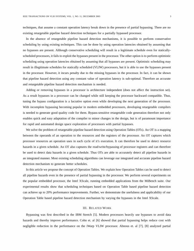
Consider the execution of an ADD operation in these pipelines. In absence of any hazards, if the ADD operation
is in F pipeline stage in cycle i, then it will be in OR pipeline stage in cycle i + 2. At this time it needs to read
the two source registers. The ADD operation will then write back the destination register in cycle i + 4, when it
reaches the WB pipeline stage. The result of the ADD operation can be read from the register file in and after cycle
i + 5.
pipeline pathdata path
F D OR EX WB
RF
Fig. 1. A 5-stage processor pipeline with no bypassing
The pipeline in Figure 1 does not have any bypasses. There is only one way to read operands, i.e., from RF.
Thus, the operation latency of ADD is 3 cycles. Any dependent operation should be scheduled at-least 3 cycles
after ADD to avoid any data hazard.
pipeline pathdata path
F OR EX WB
RF
D
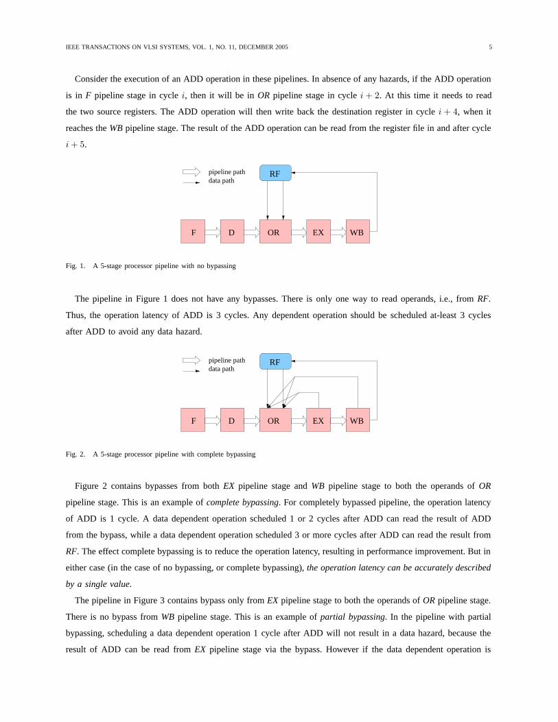
Fig. 2. A 5-stage processor pipeline with complete bypassing
Figure 2 contains bypasses from both EX pipeline stage and WB pipeline stage to both the operands of OR
pipeline stage. This is an example of complete bypassing. For completely bypassed pipeline, the operation latency
of ADD is 1 cycle. A data dependent operation scheduled 1 or 2 cycles after ADD can read the result of ADD
from the bypass, while a data dependent operation scheduled 3 or more cycles after ADD can read the result from
RF. The effect complete bypassing is to reduce the operation latency, resulting in performance improvement. But in
either case (in the case of no bypassing, or complete bypassing), the operation latency can be accurately described
by a single value.
The pipeline in Figure 3 contains bypass only from EX pipeline stage to both the operands of OR pipeline stage.
There is no bypass from WB pipeline stage. This is an example of partial bypassing. In the pipeline with partial
bypassing, scheduling a data dependent operation 1 cycle after ADD will not result in a data hazard, because the
result of ADD can be read from EX pipeline stage via the bypass. However if the data dependent operation is

IEEE TRANSACTIONS ON VLSI SYSTEMS, VOL. 1, NO. 11, DECEMBER 2005 6
pipeline pathdata path
D ORF WB
RF
EX
Fig. 3. A 5-stage processor pipeline with partial bypassing
scheduled 2 cycles after scheduling ADD, there is no way to read the result of ADD. There is a data hazard.
But again, if the data dependent operation is scheduled 3 or more cycles after ADD, then the result of the ADD
operation can be read from the RF. Thus the data hazard can be avoided by scheduling the data dependent operation
of ADD, 1 cycle after scheduling the ADD operation, or 3 or more cycles after scheduling the ADD operation.
In this case we specify the operation latency of ADD as 1, 3. In general, the operation latency of an operation
in a partially bypassed processor cannot be specified by a single value. It is a list of numbers, which indicate the
schedule-distance between the operation and the data-dependent operation to avoid any pipeline hazard. If the data
dependent operation is scheduled at any other schedule-distance, then there will be a pipeline hazard and a possible
loss in performance.
Thus due to incomplete bypassing, the operation latency of ADD cannot be accurately specified using just one
value. Unlike previous approaches that use a single value, in this paper we show how OTs can be used to accurately
pipeline hazards in the presence of such multi-valued operation latencies. The operation latency in the presence of
incomplete bypasses is very much linked to the structure of the pipeline and the presence and absence of bypasses,
and the path operation takes in the pipeline. Operation Tables define a binding between an operation and the
resources it may use and registers it will read/write/bypass in each cycle of it’s execution. Using a resource and
register model of a processor, OTs can be used to model both the data and resource hazards.
V. PROCESSOR MODEL
In this section, we define the processor and operation model. We will then define Operation Table for operations
on this processor model.
A. Pipeline Model
A pipelined processor can be divided into pipeline units by the pipeline registers. The processor pipeline can be
represented as a Directed Acyclic Graph (DAG) of the pipeline units, u i ∈ U which represent the nodes of the
DAG, and a directed edge (ui, uj) represents that operations may flow from unit u i to unit uj . There is a unique
”source node”, u0, to which there are no incoming edges. This unit generates operations. Further, some nodes are
”sink nodes”, which do not have any outgoing edges. These nodes represent writeback units. In the pipeline shown

IEEE TRANSACTIONS ON VLSI SYSTEMS, VOL. 1, NO. 11, DECEMBER 2005 7
C1 C2 C3 C4
C5
p1
p3 p4
p5
p6 p7
p9
p8
p2
LS
XWB
LWB
RF
F D OR
EX
Fig. 4. Example Pipeline
in Figure 4, F is the source unit and XWB and LWB are the writeback units. The operations flow along the block
arrows.
B. Operation Model
Each operation oi ∈ O supported by the processor is defined using an opcode o i.opcode and a list of source
and destination operands, oi.sourceOperands and oi.destOperands. The opcode defines the path of the operation
in the processor pipeline. Each source or destination operand, operand is defined by a 3-tuple, <arg, rf, rn>,
where arg is the argument of the operand, rf is the register file it belongs to, (or IMM for immediate operands),
and rn is the register number (or immediate value for immediate operands). The operand argument describes how
to read/write the operand. Thus the operation, ADD R1 R2 5, has opcode ADD, and has one destination operand
and two source operands. The destination operand is represented by <D1, RF, 1>. The first source operand is
represented as <S1, RF, 2>, and the third as <S2, IMM, 5>.
C. Pipeline Path of Operation
The pipeline path of an operation o i is the ordered list of units that an operation flows through, starting from the
unique source unit u0, to at least one of the writeback units. Each unit u i ∈ U contains a list of operations that
it supports, ui.opcodes. The add operation, ADD R1 R2 5 has opcode ADD, and the pipeline units F, D, OR, EX
and XWB have the ADD operation in the list of opcodes they support.
D. Register File
We define a register file as a group of registers that share the read/write circuitry. A processor may have multiple
register files. The processor in Figure 4 has a register file named RF.
E. Ports in Register File
A register file contains read ports and write ports to enable reading and writing of registers from and to the
register file. Register operands can be read from a register file rf via read ports, rf.readPorts, and can be written

IEEE TRANSACTIONS ON VLSI SYSTEMS, VOL. 1, NO. 11, DECEMBER 2005 8
Operation Table Definition
OperationTable := { otCycle }otCycle := unit ros wos bos dos
ros := ReadOperands { operand }wos := WriteOperands { operand }bos := BypassOperands { operand }dos := DestOperands { regNo }operand := regNo { path }path := port regConn port regFile
TABLE I
OPERATION TABLE DEFINITION
in rf via write ports, rf.writePorts. Register operands can be transferred via ports through register connections.
The register file RF in the processor in Figure 4, has two read ports (p6 and p7) and two write ports (p8 and p9).
F. Ports in Pipeline Units
A pipeline unit, ui can read register source operands via its read ports, u i.readPorts, write result operands
via its write ports, ui.writePorts, and bypass results via its bypass ports, ui.bypassPorts. Each port in a unit is
associated with an argument arg, which defines the operands that it can transfer. For example a readPort of a
unit with argument S1 can only read operands of argument S1. In the processor in Figure 4, pipeline unit OR has
2 read ports, p1 and p2 with arguments, S1 and S2 respectively. The units, XWB and LWB have write ports p4 and
p5 respectively with arguments D1, and D2 respectively while EX has a bypass port p3 with argument D1.
G. Register Connection
A register connection rc facilitates register transfer from a source port rc.srcPort to destination port rc.destPort.
In the processor diagram in Figure 4, the pipeline unit OR can read two register source operands, first from the
register file RF (via connection C1), and second from RF (via connection C2) as well as from EX (via connection
C5). The register connection C5 denotes a bypass.
H. Register Transfer Path
Register transfers can happen from a register file to a unit (register read), from a unit to a register file (a writeback
operation), and even between units (register bypass). The register transfers in our processor are modeled explicitly
via ports. A register transfer path is the list of all the resources used in a register transfer, i.e., the source port, the
register connection, the destination port, and the destination register file or unit.

IEEE TRANSACTIONS ON VLSI SYSTEMS, VOL. 1, NO. 11, DECEMBER 2005 9
VI. OPERATION TABLE
An Operation Table (OT) describes the execution of an operation in the processor. Table I describes the grammar
and structure OTs. An OT is a DAG of OTCycles, each OTcycle describes what happens in each execution cycle,
while the directed edges between OTCycles represent the time-order of OTCycles. Each OTCycle describes the
unit in which the operation is, and the operands it is reading ros, writing wos and bypassing bos in the execution
cycle. The destination operands dos are used to indicate the destination registers, and are required to model the
dynamic scheduling algorithms in the processor. Each operand that is transferred (i.e., read, written, or bypassed)
is defined in terms of the register number, regNo, and all the possible paths to transfer it. A path is descibed in
terms of the ports, register connections and the register file involved in the transfer of the operand.
Operation Table of ADD R1 R2 R3
1 F
2 D
3 OR
ReadOperands
R2
p1, C1, p6, RF
R3
p2, C2, p7, RF
p2, C5, p3, EX
DestOperands
R1, RF
4 EX
BypassOperands
R1
p3, C5, p2, OR
5 WB
WriteOperands
R1
p4, C3, p8, RF
TABLE II
OPERATION TABLE OF ADD R1 R2 R3
Table II shows the OT of the add operation, ADD R1 R2 R3 on the partially bypassed pipeline shown in Figure 4.
In the absence of any hazards, the add operation executes in 5 cycles, therefore the OT of the add operation contains
5 otCycles. In the first cycle of its execution, the add operation needs the F pipeline stage, and in the second cycle
it needs D pipeline stage. In the third cycle, the add operation occupies OR pipeline stage and needs to read its
source operands R2 and R3. All the paths to read each readOperand are listed. The first readOperand, R2 can
be read only from the RF via connection C1. There are two possible paths to read the second operand. First is
from RF via ports p7 and p2 and connection C2. The second path is from Ex via ports p3 and p2 and connection

IEEE TRANSACTIONS ON VLSI SYSTEMS, VOL. 1, NO. 11, DECEMBER 2005 10
C5. Since the sources are read in this cycle, the destOperands are listed. In the fourth cycle the add operation is
executed and needs EX pipeline stage. The result of the operation R1 is bypassed via connection C5. It can be read
as the second operand of the operation occupying the OR unit. WB pipeline stage is needed in the fifth cycle. In
the otCycle the result of the add operation R1 is written back to RF via connection C3.
VII. BYPASS REGISTER FILE
A. Size of Operation Table
The OT of an operation lists all the paths to read/write/bypass each operand. In the presence of bypasses, there
may be multiple ways to read an operand, and as a result, the OT may be large.
Consider a linear pipeline, with l pipeline stages. Suppose an operation has s source operands and d destination
operands. Further suppose that k pipeline stages can generate bypasses, and that the bypass value is available for
each operand.
In this case, the OT of the operation will have l lines, one for each pipeline stage. The operand read stage also
specifies ReadOperands. Other than 1 line to write “ReadOperands”, we need s lines for each operand. Further
there are k+1 paths to read each operand (from 1 register file, and from k bypasses). Thus 1+s+s×(K+1) lines
to specify the source operands. In addition we also need 2 lines to specify the “DestOperands”, and the destination
operand itself. Therefore, 1+s+s∗(k+1)+2 extra lines are required to specify the operand read stage. Thereafter
each pipeline stage that generates a bypass needs 3 lines to specify the “BypassOperands”, register number and the
path to bypass the operand. Thus 3k lines are needed to specify the bypassing of results. Finally we need another 3
lines to specify writing the result to the register file. The length of OT is l +(1+ s+ s× (k +1)+2)+3× (k+1).
In short, length(OT ) ∝ s× k.
Thus, the size of the OT will be large in long, extensively bypassed processors. Such large description of makes
specifying OTs error-prone. To reduce the complexity of specification, we have developed the concept of Bypass
Register File (BRF).
B. Bypass Register File
A Bypass Register File (BRF) is a virtual register file for each operand that can accept values from bypasses. All
the bypasses that can transfer the result to an operand, will now write into the BRF associated with the operand.
The operand needs to only read from the normal register files or the BRF. Thus there are only two ways to read an
operand. The semantics of BRF differ from a regular register file in the sense that the register values are valid for
only one cycle. Only one BRF is needed for each operand that can accept values from the bypasses. This greatly
reduces the complexity and redundancy in the specification of OTs.
Figure 5 shows the processor pipeline model with Bypass Register File abstraction. All the bypasses to port p2
of unit OR write into the BRF , and the second operand that has to be read via port p2, can now be read either
from the register file RF via connection C2, or from BRF via connection C6.

IEEE TRANSACTIONS ON VLSI SYSTEMS, VOL. 1, NO. 11, DECEMBER 2005 11
C2C1 C3 C4
C5
p1
p3 p4
p5
p6 p7
p9
p8
p2
p11p10
C6
OR
EX
LS
XWB
LWB
RF
BRF
F D
Fig. 5. Example Pipeline with BRF
Operation Table of ADD R1 R2 R3
1 F
2 D
3 OR
ReadOperands
R2
p1, C1, p6, RF
R3
p2, C2, p7, RF
p2, C6, p11, BRF
DestOperands
R1, RF
4 EX
BypassOperands
R1
p3, C5, p10, BRF
5 WB
WriteOperands
R1
p4, C3, p8, RF
TABLE III
OPERATION TABLE OF ADD R1 R2 R3
Table III shows the OT of the operation ADD R1 R2 R3 using the BRF abstraction. The only difference is
that the EX unit now bypasses the result to the BRF though ports p3, and p10, and connection C5, and that the
second operand in OR is read via the register file RF or via the BRF .
C. Size of OTs with BRF
In the presence of BRFs, the size of the operand read stage of pipeline will decrease. Now there are only 2 ways
to read each operand, one from the register file, and one from the BRF. Thus we just need 3 lines to specify each

IEEE TRANSACTIONS ON VLSI SYSTEMS, VOL. 1, NO. 11, DECEMBER 2005 12
operand (register number, and the two paths). Therefore only 1+3s lines are required to specify the read operands.
Summarizing, length(OT ) = l + (1 + 3s + 2) + 3× (k + 1). Thus length(OT ) ∝ s + k.
Thus BRFs are able to asymptotically decrease the size of OTs.
VIII. HAZARD DETECTION USING OPERATION TABLES
Operation Tables can be used to detect pipeline hazards in a processor, for a given schedule of instructions.
Hazard detection using OTs requires that the state of the machine (processor) be maintained to reflect the current
schedule. The state of the machine is defined in Table IV. A machineState is a ordered list (square brackets) of
macCycle. Each macCycle denotes the state of the machine resources (whether they are busy or free), and the
registers in the register files (whether they are available for read, or not). The state of the Bypass Register File also
a part of the macCycle.
Machine State
machineState := [macCycle]
macCycle := Resources, RF, BRF
TABLE IV
MACHINE STATE
The function DetectHazard described in Figure 6 is the main pipeline hazard detection function. It detects both
the data and resource hazards if the operation op is scheduled at time t in a given machineState. The function
DetectHazard tries to schedule each otCycle of the operation in the machine states starting from time t. It reports
a hazard if there is a hazard in scheduling any otCycle in the corresponding macCycle.
bool DetectHazard(machineState, Operation op, Time t)01: for (i = 0; i < op.OT.length; i + +)02: if (DetectCycleHazard(machineState[t + i], op.OT [i]))03: return TRUE04: endIf05: endFor06: return FALSE
Fig. 6. Detect Hazard when an operation is scheduled
The function DetectCycleHazard, described in Figure 7 detects a hazard when an otCycle is scheduled in
a macCycle. The function reports a hazard if a resource that is required in the otCycle is not present in the
macCycle. A hazard is reported if any readOperand cannot be read (lines 04-07), or writeOperand cannot be
written (lines 08-12). To avoid WAW (Write After Write), a hazard is reported when a destOperand is not present
in the Register File (lines 13-18).

IEEE TRANSACTIONS ON VLSI SYSTEMS, VOL. 1, NO. 11, DECEMBER 2005 13
bool DetectCycleHazard(macCycle, otCycle)/* resource hazard */01: if (otCycle.Resources �⊂ macCycle.Resources)02: return TRUE
/* all sources can be read*/03: foreach (ro ∈ otcycle.ReadOperands)04: if (AvailRP (ro.Register, ro.Paths, macCycle) == φ))05: return TRUE06: endIf07: endFor
/* all dests can be written */08: foreach (wo ∈ otcycle.WriteOperands)09: if (AvailWP (wo.Register, wo.Paths, macCycle) == φ))10: return TRUE11: endIf12: endFor
/* dest is not available */13: foreach (do ∈ otcycle.DestOperands)14: regF ile = do.RegisterF ile15: if (do.Register �∈ macCycle.regF ile)16: return TRUE17: endIf18: endFor
/* no hazard */19: return FALSE
Fig. 7. Detecting Hazards when a cycle of Operation Table is scheduled
The function AvailRP in Figure 8 tells whether the register reg can be read via any paths in the macCycle.
A register can be read by a path if the register is present in the RegFile (line 04) and all the resources required
to read the register from the RegFile are available (line 03). A register can be read if it can be read by any path
(line 01, 05). Similarly, the function AvailWP indicates if the register reg can be written via any of the paths in
the macCycle. The register can be written in the RegFile in cycle macCycle (line 13) if all the resources in any
path (line 10) are available in the macCycle (line 12).
The function DetectHazard is thus able to tell, if there is a hazard in scheduling an operation in certain cycle,
given the state of the machine. For this to function correctly, the state of the machine needs to be maintained. The
function AddOperation in Figure 9 updates the machine state after scheduling operation op in cycle t. It finds
the earliest macCycle to schedule each otCycle without a hazard (lines 03-04), and then updates the macCycle.
Each machineState is updated by scheduling an otCycle by the function AddCycle (line 06).
The function AddCycle in Figure 10 updates a macCycle by scheduling an otCycle in it. A macCycle is
updated by removing all the Resources required in otCycle from the Resources in macCycle (line 01). All the

IEEE TRANSACTIONS ON VLSI SYSTEMS, VOL. 1, NO. 11, DECEMBER 2005 14
path AvailRP(reg, paths, macCycle)01: foreach (path ∈ paths)02: regF ile = path.RegisterF ile03: if (path.Resources ⊂ macCycle.Resources)04: if (reg ∈ macCycle.regF ile)05: return path06: endIf07: endIf08: endFor09: return φ
path AvailWP(reg, paths, macCycle)10: foreach (path ∈ paths)11: regF ile = path.RegisterF ile12: if (path.Resources ⊂ macCycle.Resources)13: return path14: endIf15: endFor16: return φ
Fig. 8. Finding the available read and write path
void AddOperation(machineState, op, t)01: j = t02: for (i = 0; i < op.OT.length; i + +)03: while (DetectHazard(machineState[j], op.OT [i])04: j + +05: endWhile06: AddCycle(machineState[j], op.OT [i])07: endFor
Fig. 9. Update the state of the machine
required resources for the operand reads (lines 02-05) and writes (lines 06-11) are also marked as busy. If there are
DestOperands, RemRegFromRegFile removes the Register from RF in the later cycles (lines 12-15). The
function AddRegToRegF ile, adds the WriteOperands to RF in the later cycles (line 10).
In the next sections we show that the DetectHazard function, and the AddOperation function can be used to
detect all the pipeline hazards using Operation Tables. Thereafter we discuss how these fundamental functions can
be used to improve most existing standard scheduling algorithms.
IX. ILLUSTRATIVE EXAMPLE
Consider scheduling the sequence of three operations in the pipeline in Figure 5.
MUL R1 R2 R3 (R1← R2×R3)
ADD R4 R2 R3 (R4← R2 + R3)
SUB R5 R4 R2 (R5← R4−R2)

IEEE TRANSACTIONS ON VLSI SYSTEMS, VOL. 1, NO. 11, DECEMBER 2005 15
void AddCycle(macCycle, opcycle)/* make the resources busy */01: macCycle.Resources− = macCycle.Resources
/* mark the resources used in read as busy */02: foreach (ro ∈ otcycle.ReadOperands)03: path = AvailRP (ro.Register, ro.Paths, macCycle)04: macCycle.Resources− = path.Resources05: endFor
/* mark the resources used in write as busy */06: foreach (wo ∈ otcycle.WriteOperands)07: reg = wo.Register08: path = AvailWP (wo.Register, wo.Paths, macCycle)09: macCycle.Resources− = path.Resources10: AddRegToRegF ile(reg, path.RegisterF ile, j)11: endFor
/* remove the dest register */12: foreach (do ∈ otcycle.DestOperands)13: reg = do.Register14: regF ile = do.RegisterF ile15: RemRegToRegF ile(reg, regF ile, j)16: endFor
Fig. 10. Update a machine cycle
The OTs of ADD and SUB are similar, except for the register indices. The MUL operation uses the same
resources but spends two cycles in the EX pipeline stage. An operation bypasses the results only after the execution
has finished. Thus a valid bypass from EX pipeline stage will be generated only in the second cycle of execution
of MUL.
Since MUL occupies the EX pipeline stage for two cycles, a resource hazard should be detected between the
MUL and ADD operation. SUB requires the result of ADD operation as the first operand, for which there is no
bypass, so there should be a data hazard. We illustrate the detection of hazards by scheduling these three operations
in-order. Initially We assume that all the resources are free and that all the registers are available in the RF. There
is no hazard when MUL is scheduled in the first cycle. Table V shows the machineState after MUL is scheduled
by AddOperation.
If we try to schedule ADD in the next cycle, DetectHazard detects a resource hazard. There is a resource hazard
when the fourth otCycle of ADD is tried in the fifth macCycle. The resource EX is not free in the macCycle.
Table VI shows the machineState after scheduling ADD in the second cycle using AddOperation.
Now in the existing schedule in Table VI, if we try to schedule SUB in the third cycle, there is a data conflict.
The third otCycle of SUB cannot read R4 from RF. AvailRP returns φ because even though the connection C1 is

IEEE TRANSACTIONS ON VLSI SYSTEMS, VOL. 1, NO. 11, DECEMBER 2005 16
Cycle Busy Resources !RF BRFMUL R1 R2 R3 ADD R4 R2 R3 SUB R5 R4 R2
1 F - -2 D - -3 OR, p1, C1, p6, p2, C2, p7 - -4 EX R1 -5 EX, p3, C4, p10 R1 R16 WB, p4, C3, p8 R1 -7 - -8 - -9 - -
10 - -11 - -
TABLE V
SCHEDULE AFTER SCHEDULING MUL R1 R2 R3
Cycle Busy Resources !RF BRFMUL R1 R2 R3 ADD R4 R2 R3 SUB R5 R4 R2
1 F - -2 D F - -3 OR, p1, C1, p6, p2, C2, p7 D - -4 EX OR, p1, C1, p6, p2, C2, p7 R1 -5 EX, p3, C4, p10 Resource Hazard R1, R4 R16 WB, p4, C3, p8 EX, p3, C4, p10 R1, R4 R47 WB, p4, C3, p8 R4 -8 - -9 - -
10 - -11 - -
TABLE VI
SCHEDULE AFTER SCHEDULING ADD R4 R4 R3
free, R4 is not present in RF. The data hazard is resolved in the eighth cycle of machineState. Table VII shows
machineState after SUB is scheduled in the third cycle using AddOperation.
Thus Operation Tables can be used to accurately detect both data and resource conflicts, even in the presence of
incomplete bypassing.
X. INTEGRATING OTS IN A SCHEDULER
Detection of pipeline hazards is a fundamental problem in scheduling. Our OT-based approach generates accurate
hazard detection information, allowing any traditional scheduling algorithm to perform better. For the sake of
illustration, we demonstrate how to modify a simple list scheduling algorithm to use Operation Tables. We believe
OTs can similarly be integrated into other scheduling formulations. The scheduling problem is to schedule the
vertices of a data dependence graph G = (V, E), where each vertex corresponds to an operation, and there is an
edge between vi and vj if vj uses the result of vi. Vertex v0 and vn are the unique start and end vertices. The
function parents(v) gives a list of all the parents of v.
Figure 11 maintains three sets of vertices, U , the unscheduled vertices, F , the frontier vertices or the vertices
that are ready to be scheduled, and S, the vertices that have been scheduled (line 01). We initialize the algorithm by
scheduling the vertex start vertex v0. Therefore, U = V −v0, F = φ, and S = v0. The schedule time for each vertex

IEEE TRANSACTIONS ON VLSI SYSTEMS, VOL. 1, NO. 11, DECEMBER 2005 17
Cycle Busy Resources !RF BRFMUL R1 R2 R3 ADD R4 R2 R3 SUB R5 R4 R2
1 F - -2 D F - -3 OR, p1, C1, p6, p2, C2, p7 D F - -4 EX OR, p1, C1, p6, p2, C2, p7 D R1 -5 EX, p3, C4, p10 Resource Hazard Data Hazard R1, R4 R16 WB, p4, C3, p8 EX, p3, C4, p10 Data Hazard R1, R4 R47 WB, p4, C3, p8 Data Hazard R4 -8 OR, p1, C1, p6, p2, C2, p7 R5 -9 EX, p3, C4, p10 R5 R510 WB, p4, C3, p8 R5 -11 - -
TABLE VII
SCHEDULE AFTER SCHEDULING SUB R5 R4 R2
is initialized to 0 (schedT ime[v] = 0, ∀v ∈ V ) (lines 02-04). For scheduling, the frontier set of unscheduled vertices
is computed in each step. All unscheduled vertices (v ∈ U ) whose parents have been scheduled (parents(v) ⊂ S)
belong to the frontier set. (line 06) The vertices in the frontier set are sorted by some priority function (line 07), and
the vertex with the least cost is picked for scheduling (line 08). The minimum schedule time for v is the maximum
of the schedule time plus the latency of each parent vertex p (line 09). The vertex v is then scheduled in the first
cycle, when it does not cause a hazard (lines 10-13). Different implementations of list scheduling mainly differ in
the priority function for the frontier set.
ListSchedule(V)01: U = V − v0; F = φ; S = v0
/* initialize */02: foreach (v ∈ V )03: schedT ime[v] = 004: endFor
/* list schedule */05: while (U �= φ)06: F = {v|v ∈ U, parents(v) ⊂ S}07: F.sort() /* some priority function */08: v = F.pop()09: t = MAX(schedT ime(p) + p.OL), p ∈ parents(v)10: while (DetectHazard(v, t))11: t + +12: endWhile13: schedT ime[v] = t14: endWhile
Fig. 11. Original List Scheduling Algorithm
However in the presence of partial bypassing, the operation latency of an operation is not sufficient to avoid all the
data hazards; Operation Tables are needed. The traditional list scheduling algorithm can be very easily modified to

IEEE TRANSACTIONS ON VLSI SYSTEMS, VOL. 1, NO. 11, DECEMBER 2005 18
make use of the DetectHazard and AddOperation functions to schedule using Operation Tables. Figure 12 shows
the same list scheduling algorithm that uses Operation Tables for pipeline hazard detection. The only modification
required is to change the DetectHazard function (line 09) and the AddOperation function (line 12). Our new
Operation Table based DetectHazard function defined in Figure 6 is used. The AddOperation function is needed
to update the machineState that is a input parameter in the DetectHazard function.
ListScheduleUsingOTs(V)01: U = V − v0; F = φ; S = v0
/* initialize */02: foreach (v ∈ V )03: schedT ime[v] = 004: endFor
/* list schedule */05: while (U �= φ)05: F = {v|v ∈ U, parents(v) ⊂ S}06: F.sort() /* some priority function */07: v = F.pop()08: t = MAX(schedT ime(p)), p ∈ parents(v)09: while (DetectHazard(machineState, v.OT, t))10: t + +11: endWhile12: AddOperation(machineState, v.OT, t)13: schedT ime[v] = t14: endWhile
Fig. 12. List Scheduling algorithm using Operation Tables
Thus we have demonstrated the integration of the Operation Table based pipeline hazard detection mechanism
into the standard list scheduling algorithm. Pipeline hazard detection being a very important and distinct part in
most scheduling algorithms enables easy swapping by our more accurate OT-based technique. Thus most existing
scheduling algorithms should be able to leverage the accurate pipeline hazard detection mechanism to generate
better schedules.
XI. EXPERIMENTS
To demonstrate the need and efficacy of Operation Tables, we perform experiments on the popular embedded
processor, the Intel XScale [17], employed in wireless and hand-held devices. The Intel XScale provides high
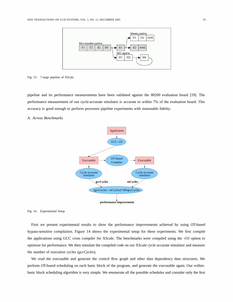
code density, high performance and low power, all at the same time. Figure 13 shows the 7-stage out-of-order
superpipeline of XScale. XScale implements dynamic scheduling using register scoreboarding, and has a partially
bypassed pipeline. We present experimental results on the benchmarks from MiBench [18] suite, which are the
representative of typical embedded applications. To estimate the performance of compiled code we have developed
a cycle-accurate simulator of the Intel XScale processor pipeline. Our simulator structurally models the Intel XScale
IEEE TRANSACTIONS ON VLSI SYSTEMS, VOL. 1, NO. 11, DECEMBER 2005 19
Fig. 13. 7-stage pipeline of XScale
pipeline and its performance measurements have been validated against the 80200 evaluation board [19]. The
performance measurement of our cycle-accurate simulator is accurate to within 7% of the evaluation board. This
accuracy is good enough to perform processor pipeline experiments with reasonable fidelity.
A. Across Benchmarks
OT-basedCompiler
Executable Executable
Application
GCC -O3
simulatorCycle-accurate
simulatorCycle-accurate
(gccCycles - otCycles)*100/gccCycles
gccCycles otCycles
performance improvement
Fig. 14. Experimental Setup
First we present experimental results to show the performance improvements achieved by using OT-based
bypass-sensitive compilation. Figure 14 shows the experimental setup for these experiments. We first compile
the applications using GCC cross compiler for XScale. The benchmarks were compiled using the -O3 option to
optimize for performance. We then simulate the compiled code on our XScale cycle accurate simulator and measure
the number of execution cycles (gccCycles).
We read the executable and generate the control flow graph and other data dependency data structures. We
perform OT-based scheduling on each basic block of the program, and generate the executable again. Our within-
basic block scheduling algorithm is very simple. We enumerate all the possible schedules and consider only the first

IEEE TRANSACTIONS ON VLSI SYSTEMS, VOL. 1, NO. 11, DECEMBER 2005 20
1000 schedules. The instructions are re-ordered to match with the best performing schedule and the new executable
is generated. We simulate the new executable on the same XScale cycle accurate simulator and measure the number
of execution cycles (otCycles). The percentage performance improvement is computed as gccCycles−otCyclesgccCycles ×100.
We perform exhaustive scheduling within the basic blocks. Exhaustive scheduling must have exponential time
complexity, but data dependencies limit the number of possible schedules. As a result the OT-based rescheduling
time for all the benchmarks is below 1 minute.
Performance Improvement
0
5
10
15
20
25
Basicmath
Bitcount
Qsort
Susan.smoothing
Susan.corners
Susan.edges
Dijkstra
Benchmarks
Fig. 15. Experimental Results
Figure 15 plots the percentage performance improvement over various benchmarks. The graph shows that our
code generation scheme can generate up to 20% better performing code than the best performing code generated
by GCC. susan.corners is an image processing algorithm that finds the corners in a given image. Our compiler
was able to detect data conflicts in two innermost loops of the corner detection algorithm, and was able to find a
schedule that avoided the conflict. In the bitcount benchmark, the scheduling could not find a better schedule than
GCC in the frequently executed loops. It could find at least one instance of data hazard (undetected by GCC) in
some other loop, and was able to avoid it, but since the loop was not among the most frequently executed loop
the performance difference was not significant. In the qsort benchmark, although our detection hazard could detect
some sub-optimal schedules, it was not possible to avoid them by re-ordering alone. We surmise that if OT-based
hazard detection technique is implemented as a first-class technique in the main compiler flow, much better results
can be achieved. Another reason that reduces the effectiveness of our schedule is due to the variation of latencies
of operations, especially the memory latencies. OT-based compiler generates a precise schedule for a given flow of
instructions in the pipeline and their latencies. Any variation in the latencies disturbs the quality of the schedule
generated. In the benchmark susan.edges, the high rate of cache misses disturbed the generated schedule so much
that very little improvement was achieved. Although the benefits achieved by a scheduler using OTs may be small,
it is always beneficial. In fact for our set of benchmarks, OT-based compiler on an average generates 8% better
IEEE TRANSACTIONS ON VLSI SYSTEMS, VOL. 1, NO. 11, DECEMBER 2005 21
performing schedule than the best performing schedule generated by GCC.
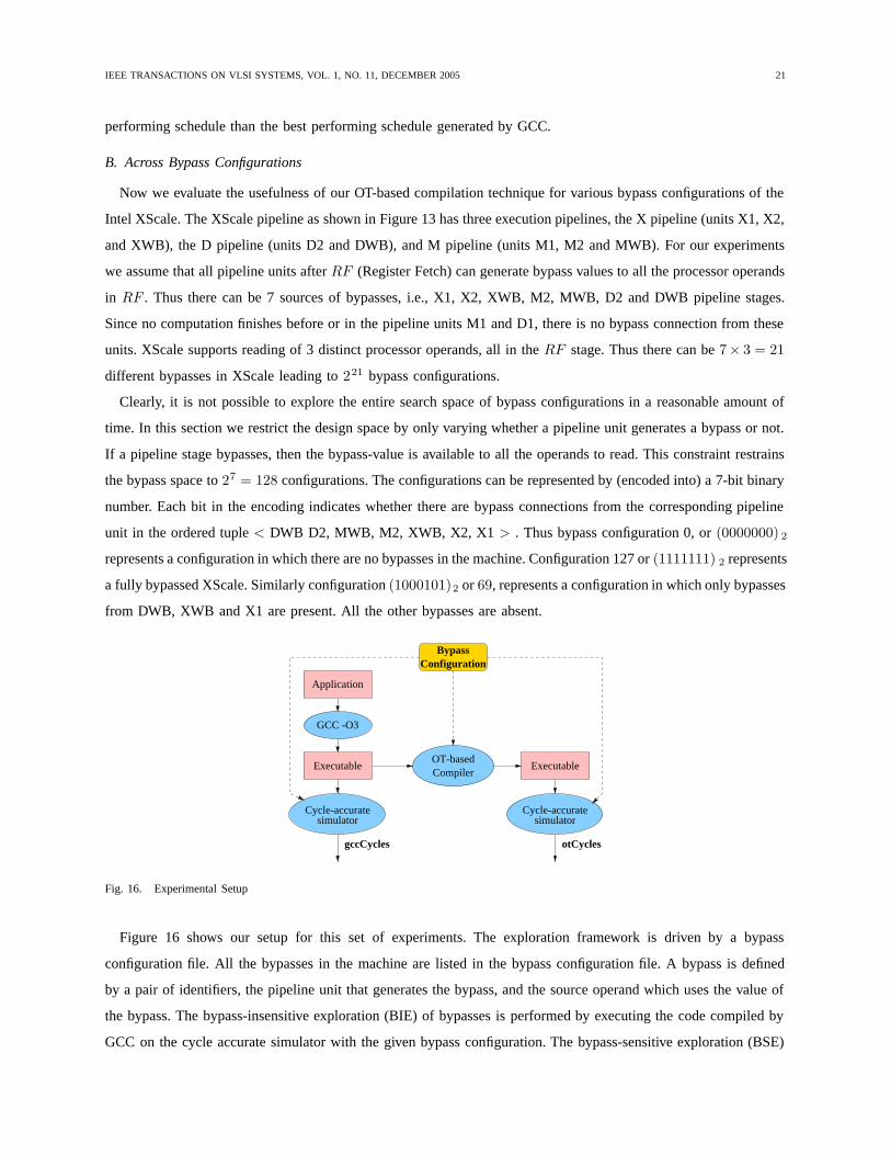
B. Across Bypass Configurations
Now we evaluate the usefulness of our OT-based compilation technique for various bypass configurations of the
Intel XScale. The XScale pipeline as shown in Figure 13 has three execution pipelines, the X pipeline (units X1, X2,
and XWB), the D pipeline (units D2 and DWB), and M pipeline (units M1, M2 and MWB). For our experiments
we assume that all pipeline units after RF (Register Fetch) can generate bypass values to all the processor operands
in RF . Thus there can be 7 sources of bypasses, i.e., X1, X2, XWB, M2, MWB, D2 and DWB pipeline stages.
Since no computation finishes before or in the pipeline units M1 and D1, there is no bypass connection from these
units. XScale supports reading of 3 distinct processor operands, all in the RF stage. Thus there can be 7× 3 = 21
different bypasses in XScale leading to 221 bypass configurations.
Clearly, it is not possible to explore the entire search space of bypass configurations in a reasonable amount of
time. In this section we restrict the design space by only varying whether a pipeline unit generates a bypass or not.
If a pipeline stage bypasses, then the bypass-value is available to all the operands to read. This constraint restrains
the bypass space to 27 = 128 configurations. The configurations can be represented by (encoded into) a 7-bit binary
number. Each bit in the encoding indicates whether there are bypass connections from the corresponding pipeline
unit in the ordered tuple < DWB D2, MWB, M2, XWB, X2, X1 > . Thus bypass configuration 0, or (0000000) 2
represents a configuration in which there are no bypasses in the machine. Configuration 127 or (1111111) 2 represents
a fully bypassed XScale. Similarly configuration (1000101)2 or 69, represents a configuration in which only bypasses
from DWB, XWB and X1 are present. All the other bypasses are absent.
BypassConfiguration
Application
GCC -O3
Executable
simulatorCycle-accurate
OT-basedCompiler
Executable
simulatorCycle-accurate
gccCycles otCycles
Fig. 16. Experimental Setup
Figure 16 shows our setup for this set of experiments. The exploration framework is driven by a bypass
configuration file. All the bypasses in the machine are listed in the bypass configuration file. A bypass is defined
by a pair of identifiers, the pipeline unit that generates the bypass, and the source operand which uses the value of
the bypass. The bypass-insensitive exploration (BIE) of bypasses is performed by executing the code compiled by
GCC on the cycle accurate simulator with the given bypass configuration. The bypass-sensitive exploration (BSE)
IEEE TRANSACTIONS ON VLSI SYSTEMS, VOL. 1, NO. 11, DECEMBER 2005 22
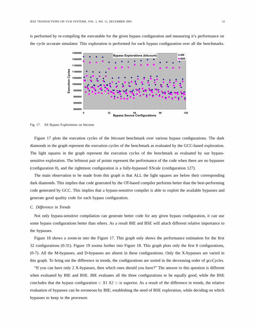
is performed by re-compiling the executable for the given bypass configuration and measuring it’s performance on
the cycle accurate simulator. This exploration is performed for each bypass configuration over all the benchmarks.
Bypass Explorations (bitcount)
800000
850000
900000
950000
1000000
1050000
1100000
1150000
1200000
1250000
0 32 64 96 128Bypass Source Configurations
Exe
cuti
on
Cy
cles
BIE
BSE
Fig. 17. All Bypass Explorations on bitcount
Figure 17 plots the execution cycles of the bitcount benchmark over various bypass configurations. The dark
diamonds in the graph represent the execution cycles of the benchmark as evaluated by the GCC-based exploration.
The light squares in the graph represent the execution cycles of the benchmark as evaluated by our bypass-
sensitive exploration. The leftmost pair of points represent the performance of the code when there are no bypasses
(configuration 0), and the rightmost configuration is a fully-bypassed XScale (configuration 127).
The main observation to be made from this graph is that ALL the light squares are below their corresponding
dark diamonds. This implies that code generated by the OT-based compiler performs better than the best-performing
code generated by GCC. This implies that a bypass-sensitive compiler is able to exploit the available bypasses and
generate good quality code for each bypass configuration.
C. Difference in Trends
Not only bypass-sensitive compilation can generate better code for any given bypass configuration, it can use
some bypass configurations better than others. As a result BIE and BSE will attach different relative importance to
the bypasses.
Figure 18 shows a zoom-in into the Figure 17. This graph only shows the performance estimation for the first
32 configurations (0-31). Figure 19 zooms further into Figure 18. This graph plots only the first 8 configurations,
(0-7). All the M-bypasses, and D-bypasses are absent in these configurations. Only the X-bypasses are varied in
this graph. To bring out the difference in trends, the configurations are sorted in the decreasing order of gccCycles.
“If you can have only 2 X-bypasses, then which ones should you have?” The answer to this question is different
when evaluated by BIE and BSE. BIE evaluates all the three configurations to be equally good, while the BSE
concludes that the bypass configuration < X1 X2 > is superior. As a result of the difference in trends, the relative
evaluation of bypasses can be erroneous by BIE; establishing the need of BSE exploration, while deciding on which
bypasses to keep in the processor.

IEEE TRANSACTIONS ON VLSI SYSTEMS, VOL. 1, NO. 11, DECEMBER 2005 23
Slice of Bypass Explorations (bitcount)
900000
950000
1000000
1050000
1100000
1150000
1200000
1250000
0 8 16 24 32Bypass Configuration
Exe
cuti
on
Cyc
les
BIE
BSE
Fig. 18. All Bypass Explorations on bitcount
X Bypass Exploration (bitcount)
850000
900000
950000
1000000
1050000
1100000
1150000
1200000
-XWB X1 X2
XWB X2X2 X1
XWB X1
XWB X2 X1
Bypass Configuration
Exe
cuti
on
Cyc
les
BIE
BSE
Fig. 19. All Bypass Explorations on bitcount
Similar trends of the effectiveness of our OT-based compiler can be seen in other benchmarks also. Figure 20
shows the results of bypass configuration exploration on qsort application.
Thus OT-based compilers are not only able to generate good code across benchmarks, but also across different
bypass configurations. Further, BIE can lead to incorrect design decisions, and therefore BSE is neccessary. Operation
Tables provide the neccessary technology to perform BSE.
XII. SUMMARY
Although register bypassing increases performance by eliminating certain data hazards, it has significant impact
on the wiring area, cost, power and complexity of the processor. As a result, designers are implementing partial
bypassing in modern embedded processors. In the presence of partial bypassing, the operation latency is no longer
a constant. Therefore traditional pipeline hazard detection mechanisms that use constant operation latency break
down in the presence of partial bypassing.
In this article we presented the concept of Operation Tables. Operation Table is a mapping between an operation
and the processor resources and registers. Operation Tables can be used to accurately detect all the pipeline hazards

IEEE TRANSACTIONS ON VLSI SYSTEMS, VOL. 1, NO. 11, DECEMBER 2005 24
Bypass Explorations (qsort)
200000
220000
240000
260000
280000
300000
320000
0 32 64 96 128
Bypass Configurations
Exe
cuti
on
Cyc
les
BIE
BSE
Fig. 20. All Bypass Explorations on qsort
even in a partially bypassed processor. In this article we have shown that our accurate pipeline hazard detection
mechanism is generic and can be used in most existing scheduling algorithms. Our experiments on MiBench and
the Intel XScale show that OT-based pipeline hazard detection mechanism can be used to achieve up to 20%
performance improvements over the best performing code generated by GCC. Further, we have demonstrated the
show usefulness and effectiveness of our technique over various bypass configurations.
The decision of adding/removing bypasses is now done either manually, or by using a simulation-only exploration.
Simulation-only exploration is performed by executing the same binary on processor models with varying bypass
configurations. However since the application is not recompiled, this leads to an error in the evaluation of the
effectiveness of the bypass configuration. Thus a Compiler-in-the-Loop exploration of the partial bypass design
space is needed. We are currently developing an automated framework for such exploration.
REFERENCES
[1] P. Hennessy and D. A. Patterson, Computer Architecture: A Quantitative Approach, 1990.[2] P. Ahuja, D. W. Clark, and A. Rogers, “The performance impact of incomplete bypassing in processor pipelines,” in Proc. of Symposium
on Microarchitecture MICRO-28, 1995.[3] P. Grun, A. Halambi, N. Dutt, and A. Nicolau, “RTGEN: An algorithm for automatic generation of reservation tables from architectural
descriptions,” in ISSS, 1999.[4] S. Muchnick, Advanced Compiler Design and Implementation, 1998.[5] E. Bloch, “The engineering design of the stretch computer,” in Proc. of Eastern Joint Computer Conference, 1959, pp. 48–59.[6] R. Cohn, T. Gross, M. Lam, and P. Tseng, “Architecture and compiler tradeoffs for a long instruction word microprocessor,” in Proc. of
ASPLOS, 1989.[7] A. Abnous and N. Bagerzadeh, “Pipelining and bypassing in a vliw processor,” in IEEE trans. on Parallel and Distributed Systems, 1995.[8] J. Gray, A. Naylor, A. Abnous, and N. Bagherzadheh, “Viper: A vliw integer microprocessor,” in IEEE Journal of Solid State Circuits,
1993, pp. 1377–1383.[9] M. Buss, R. Azavedo, P. Centoducatte, and G. Araujo, “Tailoring pipeline bypassing and functional unit mapping for application in clustered
vliw architectures,” in Proc. of CASES, 2001.[10] K. Fan, N. Clark, M. Chu, K. V. Manjunath R. Ravindran, M. Smelyanskiy, and S. Mahlke, “Systematic register bypass customization
for application-specific processors,” in Proc. of IEEE Intl. Conf. on ASSAP, 2003.[11] E. S. Davidson, “The design and control of pipelined function generators,” Int. IEEE Conf. on Systems Networks and Computers, pp.
19–21, 1971.[12] T. Muller, “Employing finite automata for resource scheduling,” in Proc. of Symposium on Microarchitecture MICRO-27, 1993.[13] T. A. Proebsting and C. W. Fraser, “Detecting pipeline structural hazards quickly,” in Proc. of ACM SIGPLAN-SIGACT Symp. on PLDI,
1994.[14] P. G. Lowney, S. M. Freudenberger, . T. J. Karzes, W. D. Lichtenstein, . R. P. Nix, J. S. O’Donnell, and . J. C. Ruttenberg, “The Multiflow
Trace Scheduling compiler,” The Journal of Supercomputing”, vol. 7, no. 1-2, pp. 51–142, 1993.[15] The Trimaran Compiler Infrastructure for Instruction Level Parallelism, The Trimaran Consortium.[16] A. Halambi, P. Grun, V. Ganesh, A. Khare, N. Dutt, and A. Nicolau, “EXPRESSION: A language for architecture exploration through
compiler/simulator retargetability,” in Proceedings of Design Automation and Test in Europe, 1999.

IEEE TRANSACTIONS ON VLSI SYSTEMS, VOL. 1, NO. 11, DECEMBER 2005 25
[17] Intel XScale(R) Core Developer’s Manual, Intel Corporation, http://www.intel.com/design/intelxscale/273473.htm.[18] M. R. Guthaus, J. S. Ringenberg, D. Ernst, T. M. Austin, T. Mudge, and R. B. Brown, “Mibench: A free, commercially representative
embedded benchmark suite,” in IEEE Workshop in workload characterization, 2001.[19] Intel 80200 Processor based on Intel XScale Microarchitecture, Intel Corporation, http://www.intel.com/design/iio/manuals/273411.htm.