Embed Size (px)
Citation preview
Power and Thermal-Aware Workload Allocationin Heterogeneous Data Centers
Abdulla M. Al-Qawasmeh, Sudeep Pasricha, Member, IEEE, Anthony A. Maciejewski, Fellow, IEEE, andHoward Jay Siegel, Fellow, IEEE
Abstract—Many of today’s data centers experience physical limitations on the power needed to run the data center. The first problem thatwe study is maximizing the performance (quantified by the reward collected for completing tasks by their individual deadlines) of adata center that is subject to total power consumption (of compute nodes and CRAC units) and thermal constraints. The second problemthat we study is how to minimize the power consumption in a data center while guaranteeing that the overall performance does not dropbelowa specified threshold. For both problems,wedevelop novel optimization techniques for assigning the performance states of cores atthe data center level to optimize the operation of the data center. The resourceallocation (assignment) techniques in this paper are thermalaware as they consider effects of performance state assignments on temperature and power consumption by the CRAC units. Oursimulation studies show that in some cases our assignment technique achieves about 17%average improvement in the reward collected,andabout 9% reduction in power consumption compared to anassignment technique that only considers putting a core in the performancestate with the highest performance or turning the core off.
Index Terms—Thermal-aware, performance states, data center, CRAC, heterogeneous computing
1 INTRODUCTION
OVER the last decade, the power consumption of datacenters has been increasing at a rapid rate. In a report
by the EPA [18], it is estimated that the power consumed byservers and data centers has more than doubled between theyears 2000 and 2006. In 2006, it is estimated that the powerconsumed by servers and data centers was 61 billion kWh,which is equal to 1.5%of the total U.S. electricity consumptionthat year. This amounts to billion in annual electricitycosts, equivalent to thepower consumption costs of 5.8millionaverageU.S. households.Motivated by the need to reduce thepower consumption of data centers, many researchers havebeen investigating methods to increase the energy efficiencyin computing at different levels: chip, server, rack, and datacenter (e.g., [2], [7], [8], [10], [14], [21], [24], [28], [29], [32], [36],[40], [45]).
In some cases, there are physical limitations on the amountof power available for data centers. For example, MorganStanley is no longer able physically to get the power needed torun a new data center in Manhattan [11]. In a survey of datacenters [19], 31% identify power availability as a key factorlimiting server deployment. The EPA report also indicatesthat about 50% of the power consumed in data centers is dueto the infrastructure for power delivery and cooling.
Therefore, minimizing the power consumed by the coolinginfrastructure, can lead to significant overall power savings.
This paper studies two problems. In Problem 1, we maxi-mize the performance of a data center that is subject to both atotal power consumption constraint ( ) and thermal con-straints. The power consumption of the data center is the sumof the power consumption of both Computer Room AirConditioning (CRAC) units and compute nodes. We quantifythe performance of the data center as the total rewardcollected from completing tasks in a workload by their indi-vidual deadlines.We consider a data center in the steady statewhere task flow rates, temperatures at compute nodes andCRAC units, and the power consumption of compute nodesbecome constant;we assume that the steady statemay take ondifferent values during subsequent time intervals. Therefore,the performance is equivalently quantified by the total rate atwhich reward is collected (the total reward rate). In Problem 2,we minimize the power consumption of a data center whileguaranteeing that the total reward rate does not drop below aspecified threshold ( 1).
Performance states (P-states) of cores provide a trade-offbetween the power consumed by a core and its performance[23]. Lower P-states consume more power and provide better perfor-mance. The relationship between the performance and powerconsumption of the P-states is non-linear. In most cases, thelowest P-state (P0) is not the P-state with the best trade-offbetween performance and power consumption [30], [41].
P-state assignments in data centers are mainly done at thecompute node level. In cases where the workload fluctuates,the P-state of one or more cores is increased when the node’sutilization drops below a specified threshold (e.g., [17], [35],
• A.M.Al-Qawasmeh, S. Pasricha, A.A.Maciejewski, andH.J. Siegel are withthe Department of Electrical and Computer Engineering, Colorado StateUniversity, Fort Collins, CO 80523.E-mail: [email protected], sudeep, aam, [email protected].
• H.J. Siegel is also with the Department of Computer Science, Colorado StateUniversity, Fort Collins, CO 80523.
Manuscript received 20 Sept. 2012; revised 31 Mar. 2013; accepted 12 May2013. Date of publication 21 May 2013; date of current version 16 Jan. 2015.Recommended for acceptance by D. Bader.For information on obtaining reprints of this article, please send e-mail to:[email protected], and reference the Digital Object Identifier below.Digital Object Identifier no. 10.1109/TC.2013.116
1. Appendix C, which can be found on the Computer Society DigitalLibrary at https://doi.ieeecomputersociety.org/10.1109/TC.2013.116,provides a list of notations used in this paper.
IEEE TRANSACTIONS ON COMPUTERS, VOL. 64, NO. 2, FEBRUARY 2015 477
0018-9340 © 2013 IEEE. Personal use is permitted, but republication/redistribution requires IEEE permission.See http://www.ieee.org/publications_standards/publications/rights/index.html for more information.

[40]. However, in a power or performance constrained datacenter where the workload assigned to a core is constant, theutilization of each core (that is not turned off) in a specificP-state will be close to 100% to avoid idle time. This is becausewe want to execute as many tasks as possible to obtain themaximum performance for a given power consumption. Inthis paper, we show that our technique of assigning theP-states when considering the whole data center increasesthe overall performance (in terms of increased reward orreduced power consumption) of the data center.
The power consumed by compute nodes in the data centeris dissipated as heat that is removed by the CRAC units. Ourapproach of assigning tasks and P-states to cores is thermalaware as it considers the temperature evolution effects ofP-state assignments, which in turn affects the power con-sumed by the CRAC units. For both problems studied in thispaper, we show how each assignment can be expressed as anexact optimization problem. The P-state assignment part ofthe problem introduces integer constraints. The integer con-straints make each assignment problem not scalable withrespect to the number of cores in the data center. A simplerelaxation of the integer constraints may introduce additionalbinary constraints that make each assignment problem notscalable. To address this, we propose novel and scalableassignment techniques for both problems. Each techniqueinvolves solving a set of scalable optimization problems. Ourtechniques are compared against a technique that only con-siders putting a core in the lowest P-state or turning off thecore. We show that using our techniques results in notableperformance improvements.
In summary, we make the following novel contributions.Our first contribution is that we model data centers that arepower or reward constrained. The second contribution is thatwe express each assignment problemat the data center level asanoptimizationproblem that includes P-state assignment. Thedecisionsof thisoptimizationproblemare: theP-statesof cores,thedesirednumberoftasksperunit timeallocatedtoacore,andtheoutletCRACtemperatures.Theknownsolution techniquesto both optimization problems are not scalable due to integerconstraints imposed by the P-states. The third contribution is ascalable assignment technique to find near-optimal solutionsfor each problem. The fourth contribution is a dynamic sched-uler that assigns tasks to cores such that the actual rate of taskexecution is as close as possible to the desired rate. Finally, thefifth contribution of this research is showing, through simula-tions, the performance gains of applying our techniques tosolve Problems 1 and 2 as opposed to current techniques.
The rest of this paper is organized as follows. Section 2discusses related work. The data center model is described inSection 3. In Section 4, the thermal constraints in the datacenter are described. The assignment problems and our solu-tion to the problems are given in Section 5. Section 6 describesthe simulation set up. Simulation results are shown inSection 7. Conclusions are given in Section 8.
2 RELATED WORK
In [40], a control system for minimizing the power consump-tion in blade server enclosures is proposed. The powerconsumption of the blade server is minimized using threetechniques: blade server consolidation, adjusting the speeds
of the fans, and assigning P-states to processors. The P-stateassignment is based on a simple utilization-based technique.Aprocessor is assigned aP-state so that the utilization is neverhigher than 80%. However, as discussed in the introduction,this technique is not effective in a power or performanceconstrained data center because the utilization of each coreshould be close to 100%. The other two techniques (bladeserver consolidation and adjusting the speeds of the fans) canbe used in future work in combination with our assignmenttechnique to reduce the power consumption.
In [36], it is shown that using an integrated approach tomanaging the cooling and computational resources in a datacenter is more efficient than if the two resources were man-aged independently. Their technique is similar to ours in thatit trades-off power consumption with QoS (reward). Theytrade-off power bydeciding the amount of compute resourceswill be turned on at a compute node. In this paper, we extendthat work in two directions. First, we consider a powerconstrained data center and a reward constrained data center.Second, we show how assigning P-states at the data centerlevel results in improved performance.
The P-state assignment problem for optimizing some ob-jective in a computer systemhas been studiedwidely (e.g., [7],[8], [13], [41], [45], [46]). The primary difference between ourwork and these studies is that our work considers the powerconsumed by the CRAC units in addition to the powerconsumed by compute nodes.
The thermal-aware scheduling problem has been previ-ously researched (e.g., [2], [14], [32], [34]). However, unlikeour study, none of these papers consider P-state assignment.
Many other techniques to increase the energy efficiency ofdata centers exist. For example, the Open Compute Projectstarted by Facebook proposes the following two techniques:1) using a 480Velectrical distribution system to reduce energyloss and 2) reusing hot aisle air in the winter to heat offices.Another example proposed by the Sustainable EcosystemsResearch Group at HP is to use water evaporation for coolinginsteadofusing compressors.Manyof these techniques canbeused in conjunction with our technique to obtain furtherperformance gains.
3 DATA CENTER MODEL
3.1 OverviewIn this section, we give a detailed description of the workloadand the different components of the data center. Data centersare typically arranged in a hot-aisle/cold-aisle configuration,as depicted in Fig. 1. CRAC units draw hot air from the topand deliver cold air through the perforated floor tiles in thecold aisles. Compute nodes draw air from the cold aisles. Thepower consumption of compute nodes causes the tempera-ture inside of the compute nodes to rise. The hot air inside acompute node is expelled into the hot aisle.Due to complex airflow patterns in a data center, some of the hot air exiting acompute node re-circulates into another compute node.
3.2 WorkloadWe assume that we have a set of known task types. Thearrival rate of tasks of type is given by . The types of tasksand their arrival rates in real-world data centers may changeover time (e.g., depending on the time of day). Thismay cause
478 IEEE TRANSACTIONS ON COMPUTERS, VOL. 64, NO. 2, FEBRUARY 2015

the data center to operate at less than capacity at times and beoverloaded at other times. In this paper, we assume thathistoric data can be used to identify the types of tasks thatthe data center will be executing and estimate the arrival ratesof each of the task types in different time intervals in the future(e.g., [26]). In each of these time intervals, the arrival rate oftasks of each type remains constant. When the arrival rates oftasks change (i.e., we enter a new time interval), the assign-ment problems in this paper will be solved again for the newarrival rates.
A reward is collected for completing a task of type bythe task’s individual deadline. The deadline of a task of typeis givenby: . The value of wouldbe specified by the user. In addition, we assume tasks can bedropped if their deadlines cannot be satisfied. The goal ofProblem 1 in this paper is to maximize the total reward that iscollectedgiven a constraint on the total power consumptionofthe data center (the power consumption of compute nodesand CRAC units). The goal of Problem 2 in this paper is tominimize the total power consumption given a constraint onthe total reward collected.
3.3 Compute NodesLet the number of compute nodes in the data center be .Each compute node has a number of identical cores. Eachcompute node belongs to a specific compute node type .Compute nodes with the same type are identical (i.e., theyhave the same number and type of cores, and the same powerconsumption characteristics). The characteristic of computenodes (e.g., number of cores, the power consumption proper-ties, and/or the computational performance of cores) differsacross compute node types. The total number of cores in thedata center is . We use a global index for cores. Let
be the type of the compute node to which core belongs.Because all coreswithin a compute node are identical, we alsorefer to as being the type of core .
Thepower consumption of a compute node is the sumof itsbase power consumption and the power consumption of itscores. The base power consumption is used to model non-compute devices (e.g., disks, fans). The power consumed bythe non-compute devices is not affected by the utilization of
the cores [33]. Let be the base power consumption of acompute node of type . We assume that compute nodes arenot turned off during the execution of a workload. Therefore,the base power consumption will always be incurred even ifthe compute node is not executing any tasks.
Each core of type in the data center can be put in one ofP-states. P-state 0 is theP-statewith thehighest clock frequencyand highest power consumption. Each consecutive P-statehas a lower clock frequency and lower power consumption.We also consider the case where we can turn off the core.
Wemodel thecasewhere thecore is turnedoffbyaddingoneadditional P-state to the availableP-states of a core. The turned-off P-statewill be thehighestP-state (e.g., for coreswithP-statesfrom P0 to P5, the turned-off state will be P6). The powerconsumption of a core of type running in P-state is .
In some cases, the power consumption of a core is also afunction of the task type that it executes. For example, I/Ointensive tasks usually consume less power than other tasks[33]. In thiswork,we assume that the power consumption of acore is dependent on its type and P-state alone. However, it ispossible to extendourmodel to capture the effect of a task type(e.g., I/O or compute intensive task types) on core powerconsumption. A third index would have to be added to torepresent the effect of a task type on the power consumptionof a core. For example, for an I/Obound task type 1 the powerconsumption of a core of type running in P-state iswhich will be less than the power consumption of the samecore when it runs a CPU bound task type 2 (i.e., ).Introducing this third index will increase the size of ourassignment problems. However, the same assignment tech-niques will still be applicable.
Let be the assigned P-state of core . Let be theset of indices of cores that belong to compute node . Thepower consumption of compute node , , is given by:
The first term refers to the baseline power for a computenode j of type and the second term refers to the activeoperational power that depends on the P-state.
3.4 Estimated Computational SpeedWe assume that the estimated computational speed ( ) ofa task of type on a core of type running in P-state , ECS( , ,), is known. ECS( , , ) represents the number of tasks of typethat can be completed per time unit on a core of type when
running in P-state . The estimated computational speed isequal to the reciprocal of the estimated time to compute (ETC)[4], [5]. The assumption of ETC information is a commonpractice in resource allocation research (e.g., [9], [15], [22], [25],[27], [37], [42]). The ETC values for a given system can beobtained from user supplied information, experimental data,or task profiling and analytical benchmarking [3], [22], [27],[42]. Obviously, when the core is turned-off, the ECS of a taskof any type is 0, i.e., ECS for all and .
3.5 Computer Room AC UnitsWe assume that the number of CRAC units in a data center isNCRAC. CRACunits are used to remove the heat generated bythe compute nodes. The power consumed by a CRAC unit is
Fig. 1. A hot-aisle/cold-aisle data center layout.
AL-QAWASMEH ET AL.: POWER AND THERMAL-AWARE WORKLOAD ALLOCATION IN HETEROGENEOUS DATA CENTERS 479
equal to the ratio of the amount of heat removed at that CRACunit to theCoefficient ofPerformance (CoP) of thatCRACunit [32].
The amount of heat removed by a CRACunit depends onthe inlet air temperature, (which is directly affectedby the heat generated by compute nodes), and the assignedoutlet air temperature, (which is the temperatureof the cool air to be generated by the CRAC). Let be thedensity of air, be the specific heat capacity of air, and
be the air flow rate at CRAC unit . The amount ofheat removed per unit time at CRAC unit is equal to [39]:
The CoP of a CRAC unit is a function of its outlet tempera-ture [32]. The power consumed by CRAC unit , , isgiven by [32]
When the inlet air temperature of a CRAC unit is less thanor equal to the assigned outlet temperature (there is no heat tobe removed) the power consumption is 0.
4 THERMAL CONSTRAINTS
Due to the lawof energy conservation, thepower consumedata compute nodewill be dissipated as heat causing an increasein the temperature of the air going through the compute node.To maintain the reliability of the CRACs and compute nodes,CRAC units must remove the heat generated by the computenodes so that the inlet air temperature of the CRACs andcompute nodes are kept at or belowa redline temperature. Let
and be the inlet and outlet air temperatures atcompute node , respectively. Let be the air flow rate atcompute node . The outlet air temperature of compute nodeis given by [39]
Air flow patterns in data centers are complex. The inlettemperatures of CRAC units and compute nodes are affectedby the outlet temperatures of other CRAC units and computenodes [39]. Let
andUsing the “Abstract Heat Flow Model” proposed in [39], wecan compute each element of as a linear combination of theelements of , i.e.,
The values in matrix A can be estimated using sensormeasurements [39]. Let be the vector of redline
temperature constraints on inlet air temperatures, whichgives the constraint
The inequality is element-wise (i.e., element in vectormust be less than or equal to element in vector )
5 ASSIGNMENT PROBLEMS
5.1 OverviewGiven a workload composed of a set of tasks arriving atdifferent times, the goal of assignment Problem 1 is to maxi-mize the total reward rate subject to a constraint on themaximum total power consumption. The goal of assignmentProblem 2 is to minimize the power consumption of the datacenter subject to a constraint on the minimum reward rate.Both problems are subject to thermal constraints (i.e., theredline temperatures at the inlets must not be exceeded). Thedecisions that both assignment problems must make are:1) the P-states of cores, 2) the task to core assignments, and3) the outlet temperatures of the CRAC units.
Because we assume the arrival rates of task types remainrelatively constant during the steady state, the decision vari-ables will remain constant. When the arrival rates change,then we will have a new time interval and another optimiza-tion problem that we will have to solve to obtain the newvalues of the decision variables.
Temperature evolution in the data center is in orders ofminutes,while the execution of a task is in orders of seconds ormilliseconds. To make workload assignments tractable, pre-vious research (e.g., [2], [36]) has used a two-stage assignmentapproach. The first stage manages the power and the thermalevolution in the data center, while the second stage performsworkload balancing. In this paper, we apply the two-stageassignment approach for both of our assignment problems. Inthe first stage, our approach assigns the P-states of cores, thedesired execution rate of task types on cores, and the outlettemperatures of CRAC units. The first stage guarantees thatthe thermal constraints and the power constraint for Problem1 or the reward constraint for Problem 2 are not violated. Inthe second stage, our approach implements a dynamic sched-uler that assigns tasks to cores so that the actual execution rateof each task type on each core approaches the desired execu-tion rate set by the first step. The dynamic scheduler can alsomake the decision to drop a task. The two-stage assignment isdepicted in Fig. 2.
In Section 5.2, we focus on the first-stage assignmentproblem for solving Problem 1. The difference between thefirst-stage assignment for Problem 1 and Problem 2 is shownin Section 5.3. In Section 5.4, we propose a dynamic schedulerto assign incoming tasks to cores.
5.2 First-Stage Assignment: Problem 15.2.1 OverviewIn Section 5.2.2, we formulate the assignment problem as anexact mixed integer nonlinear program (MINLP). Because thesolution techniques for solving the exact MINLP are notscalable, we propose a scalable technique tofind near-optimalsolutions. The technique divides Stage 1 into three steps. The
480 IEEE TRANSACTIONS ON COMPUTERS, VOL. 64, NO. 2, FEBRUARY 2015

first step assigns power budgets to compute nodes, CRACoutlet temperatures, and the fraction of time each core spendsrunning tasks of each type. The second step converts thepower budget assignment into a P-state assignment for eachcore. Finally, Step 3 uses the exact P-state assignment in Step 2to assigns the desired execution rate of each task type on eachcompute node.
5.2.2 Problem FormulationThe decisions made at the first stage are: the outlet tempera-ture of each CRAC unit ( ), the P-state of each core( ), and the desired rate of executing tasks of each type oneach core. The desired rates are organized in a matrix .Entry ER( , ) represents the desired execution rate of tasks oftype on core .Once aP-state of a core is assigned,we assumethat it is not changed. Therefore, the first stage assignment isconsidered as static assignment.
The following equation shows the assignment problem forProblem 1:
subject to:
1. ,
.2.
and
3. .
4. .
5. .
The objective function is the total reward rate. The firstconstraint guarantees that the desired execution rate of tasktypes on a core will not exceed the core’s ability to completethe tasks. When the estimated execution time of a task of typeon a core of type running in P-state (i.e., 1/ECS( , , ))
is greater than , no task of type can make its deadline oncore even if its execution starts immediately after its arrival.Therefore, if , then Constraint 2 guaranteesthat to avoid executing tasks of type on core .Constraint 3 guarantees that the sum of the desired executionrate of a task type on all cores does not exceed its arrival rate.The power constraint is guaranteed by Constraint 4. Finally,Constraint 5 guarantees the thermal constraints.
Note that there are two cases where ECS values can be 0.First, when is the turned-off P-state, the ECS of any tasktype on core is 0. Second, a core type may not be able toexecute certain task types (for example, due to certain re-quired software not being installed on the correspondingnode type). When an ECS value is 0, 1/ECS will not bedefined. However, we can solve this issue by assuming thatthe ECS value is a “small enough” positive number.
The problem in Equation 7 is a MINLP for the followingtwo reasons. First, the above problem contains integer con-straints due to the requirement that the P-states be integers.Second, the measured CoP of the CRAC units at the HP LabsUtility Data Center as a function of CRAC output tempera-ture, , is given by [32]
For this CoP, the power consumption of the CRAC units(Equation 3) is nonlinear (and non-convex), which makesconstraint 4 a nonlinear (and non-convex) constraint.
MINLPs belong to the class of NP-hard problems. Findingthe optimal solution of such problems is computationallyinfeasible for large problem sizes. For example, consider acompute node that has 32 cores and that each core can be putin one of 5 P-states. This gives us P-stateassignment combinations.
In the following subsections, we show how the Stage 1assignment is divided into three steps to relax the integerP-state constraints. In the first step, instead of assigningP-states to cores, we assign power consumption to cores. Thismakes the assignment problem simpler. The decision vari-ables in the first step are the power consumption of eachcompute node, the outlet temperature of eachCRACunit, andthe fractionof time each computenode spendson tasksof eachtype. The second step converts the compute node powerassignment into a P-state assignment. The third step assignsthedesired execution rate of each task typeoneach core for theP-state assignment obtained from the second step.
5.2.3 Step 1 AssignmentRelaxing the integer P-state constraint means that we allow acore to be assigned a continuous P-state value rather than adiscrete one. Therefore, we have to define core power con-sumption and ECS functions for continuous P-states. Anotherequivalent assignment problem is to assume that cores can beassigned a continuous power value between zero and thepower consumption in P-state 0. We use this equivalent
Fig. 2. The assignment problem in the data center. The first stage assignsthe outlet temperatures of CRAC units, the P-states of cores, and thedesired execution rate of task types on cores. The second stage assignsthe incoming tasks to cores based on the desired execution rate set by thefirst step or drops tasks that cannot make their deadline.
AL-QAWASMEH ET AL.: POWER AND THERMAL-AWARE WORKLOAD ALLOCATION IN HETEROGENEOUS DATA CENTERS 481

assignment problem because it makes the representation ofthe assignment problem easier (we relate power directly withperformance), and it eliminates the need to define powerconsumption functions for continuous P-states.
For the relaxedproblem, theECSof a task of type on coreis a continuous function of the power consumption of the core.Let be the power assigned to core . Let
be the ECS for a task of type running ona core of type as a continuous function of . Tominimize the difference between the integer solution and therelaxed solution of the Step 1 assignment, we select sothat it goes through the points
Each of these points is the power consumption of a P-stateand the ECS at that P-state. Intuitively, one can view the valueof when is not equal to the power consumptionof any P-state, is to assume that the core can switch between aP-state with power consumption lower than and aP-state with a power consumption higher than suchthat the averagepower consumption is equal to. Therefore,wechose to represent using a piecewise linear function.
For example, assume a core of type with four P-states. Thepower consumption of P-states 0, 1, 2, and 3 is 0.15, 0.1, 0.05,and 0 Watts (W), respectively. The ECS values fortask type for each of the four P-states are 1.2, 0.9, 0.5, and 0,respectively. The function is a linear piecewise functionthat goes through the points (0, 0), (0.05, 0.5), (0.1, 0.9), and(0.15, 1.2). This function is shown in Fig. 3.
Because for both Problems 1 and 2 a higher ECS valuewillresult in a better solution, if the function is concave,then the computational expense of the optimization can begreatly reduced by representing the function withlinear constraints. The function, however, is notguaranteed to be concave. In that case, an equivalent repre-sentation is only achieved by introducing additional binaryconstraints. The introduction of the binary constraintswouldmake the Stage 1 optimization problem computationallyinfeasible for a large number of cores. For instance, considerthe example shown in Fig. 4 where the number of P-states isfour (i.e., ). The ECS values for the P-states 0, 1, 2, and 3are 1.2, 0.9, 0.2, and0, respectively. This function is not aconcave function.
The non-concavity of an function is caused by aP-state that has an ECS to power consumption ratio that isless than its next lower P-state. We call this P-state a “bad”P-state.For the function in Fig. 4, P-state 2 is a “bad”P-state because the ratio of its ECS to its power consumption
is 4, where the ratio of P-state 1’s ECS to its power consump-tion is 9. If we ignore P-state 2 (the “bad” P-state), then the
functionwill be concave. This case is shown in Fig. 5.Weignore “bad”P-states (i.e., donot assign a core a “bad”P-state)so that we can reduce the computational complexity of theStep 1 assignment.
In general, when the “bad” P-states are not ignored, theStep 1 assignmentwill still avoid “bad”P-states. For example,consider the case where a compute node of type has twocores. Assume that the compute node can assign a maximumof 0.1W total power to its cores. Assume that there is only onetask type and it has a reward of 1, i.e., . If the function inFig. 4 is the ECS of that compute node, then the optimalsolution in this case would be to put one of the cores in P-state1 (i.e., assign 0.1 W power to it) and the other in P-state 3 (i.e.,assign 0Wpower to it). Thiswill result in a total reward rate of0.45, which is the same as when “bad” P-states are ignored.It should be noted that the optimal value when the “bad”P-states are ignored is never better than the optimal valuewhen the “bad” P-states are not ignored.
Let be the desired fraction of time that corespends executing tasks of type . The desired execution rate oftask type on core , , is equal to
The Step 1 (relaxed) optimization problem is obtained fromEquation 7 by replacing with
and with . The effect ofConstraint 2 is captured by considering a P-state of coretype a “bad” P-state for task type if .
Fig. 3. An example function.Fig. 4. An example of a non-concave function.
Fig. 5. An illustration of the calculation of the function in Fig. 4 whenthe “bad” P-state is ignored.
482 IEEE TRANSACTIONS ON COMPUTERS, VOL. 64, NO. 2, FEBRUARY 2015
Equation 9 and its constraints represent the Step 1 optimiza-tion problem.
subject to:
1. , .
2. .
3. .
4. .
Because all the cores within a compute node are homoge-nous,wecanreduce the time tofindasolution forEquation9byassuming that all coreswithin a compute nodewill be assignedthe same value of DF for each task type and the same powerconsumption ( . This reduces the size of matrix DFand the number of ECS functions to be equal to .
The problem in Equation 9 is an NLP. To avoid locally
optimal solutions that have (i.e., core is not
fully utilized), we substitute the inequality in Constraint 1with an equality. Even with this change, a solution to Equa-tion 9 may be locally (and not globally) optimal. Differentlocally optimal solutions may be obtained from differentinitial starting points. Therefore, we try multiple randomstarting points. Details on how we decided on the numberof random start points are in Section 7 (simulation results).
5.2.4 Step 2 AssignmentThe purpose of the Step 2 assignment is to convert the powerassigned to a core into a P-state. The solution to Step 1guarantees that the power and thermal constraints are satisfied.Therefore, thepowerconsumptionat anycomputenodeshouldbe kept at or below the power consumption that resulted fromthe Step 1 assignment. We design the following heuristic toconvert the values into a P-state assignment:
1. For each core , assign it the highest possible P-state thatresults in a power consumption greater than or equal to
.2. For each compute node
While the power consumption calculated byEquation 1is greater than the power consumption that resultedfrom Step 1
Increase the P-state of the core with the smallestP-state the next non-bad P-states.
Because the functions are concave, the ECS to powerconsumption ratio of a P-state will always be lower than orequal to that of a higher P-state. Therefore, in Step 2 of theprocedure above we increase the P-state of the core with thelowest P-state. In cases where there are multiple task typesassigned to a core, we only ignore the bad P-states of the tasktype that gives the most reward rate on that core.
5.2.5 Step 3 AssignmentIn Step 3, we solve Equation 7 to determine the optimaldesired execution rate of task types on cores (i.e., the optimal
ER matrix) using the outlet temperature of CRACs that isdetermined in Step 1 and the discrete P-state assignmentdetermined in Step 2, which make the solution to Equation 7a simple linear program (LP).
5.3 First-Stage Assignment: Problem 2The exact formulation of the first-stage assignment for Prob-lem 2 is similar to the formulation of Problem 1 (given inEquation 7) except that the objective function for Problem 2 istominimize power consumption subject to a constraint on theminimum total reward rate. The exact formulation of Problem2 is also a MINLP. Therefore, we propose a three-step ap-proach for solving Problem 2. Similar to the first step ofProblem 1, the first step of Problem 2 uses the functionsto relax the integer P-state assignment constraints.
Step 2 of the first-stage assignment for Problem 2 convertsthe power consumption assignment of cores into a discreteP-state assignment. To guarantee that the total reward rateconstraint is not violated, the conversion at a specific computenode must guarantee that the cores in their assigned P-stateswill collectively be capable of executing task types at a ratethat is greater than or equal to the total desired execution ratethat is set by Step 1 for compute node .
A simple way to guarantee that the total reward rateconstraint is not violated at a compute node is to assigneach core in compute node to thehighest possible P-state thatresults in a power consumption greater than or equal to
. This guarantees the total reward rate constraintbecause we assume that .
Onemay be able to improve this simple P-state assignment(i.e., reduce the power consumption) by incrementing theP-state of some cores. However, incrementing the P-state ofany core will require reassigning the desired execution rate oftask types among the compute node cores so that the totalreward rate constraint is satisfied. We show how a mixedinteger program can be used to find the optimal P-stateassignment that satisfies the total reward rate constraints.Because finding the optimal solution of a mixed integerprogram is an NP-hard problem, we design a heuristic pro-cedure that can be used to find a near-optimal solution.
Let the reassigned desired execution rates of task types oncores be arranged inmatrix . Entry representsthe reassigned desired execution rate of task type on core .For cores in compute node , the following mixed integerprogram finds the optimal P-state assignment and reas-signed desired execution rates for cores that belong tocompute node :
subject to:
1.
2.and .
3. , .
Constraints 1 and 2 are similar to Constraints 1 and 2 inEquation 7. Constraint 3 guarantees that the total availableexecution rate for each task type at compute node is greaterthan or equal to the total desired execution rate set by Step 1.The problem in Equation 10 contains integer constraints due
AL-QAWASMEH ET AL.: POWER AND THERMAL-AWARE WORKLOAD ALLOCATION IN HETEROGENEOUS DATA CENTERS 483
to the P-state assignment that makes it computationallyintractable for many of today’s compute nodes that containa large number of cores. However, for a fixed P-state assign-ment, the problem in Equation 10 is a LP feasibility problem.We use the LP feasibility problem to test whether a specificP-state assignment satisfies the total reward rate constraints.
Wedesigned the followingprocedure to convert the powerconsumption of cores into a P-state assignment:
1. For each core , assign it the highest possible P-state thatresults in a power consumption greater than or equal to
.2. For each compute node
a. Until a feasible solution exists for Problem 10Increase the P-state of the core with the smallestP-state to the next non-bad P-state.
The output of Step 2 is a P-state assignment and the matrixRER (which now becomes the new ER). Similar to Step 2 ofProblem 1, Step 2 of Problem 2 avoids “bad” P-states.
The P-state assignment of Step 2 may violate the thermalconstraints. Therefore, Step 3 solves the exact optimizationproblem for Problem 2. Because the P-state and desiredexecution rates are determined, the exact optimization prob-lem becomes an NLP (due to the power consumption ofCRAC units).
5.4 Second Stage AssignmentThe second stage assignment for both Problems 1 and 2 is thesame. Thedynamic scheduler at the second step keeps track ofthe actual execution rate of each task type on each core inmatrix . The goal of the dynamic scheduler is tomake theratio of as close as possible to 1 for eachtask type and core .
For each incoming task , thedynamic schedulermaps to acore that can complete it before its deadline and has theminimum AER( value that is less than or equalto 1. If no such core exists, then the dynamic scheduler drops .
6 SIMULATION SETUP
6.1 OverviewWeconducted simulation studies to evaluate the effectivenessof our assignment technique. In this section,we showhow theparameters of the simulations were generated.
Real-worlddata centers can varywidely in the number andtype of compute nodes, the number and type of CRAC units,and the arrival rate and type of task types. For illustrationpurposes,we set upour simulationswith eight task types, twocompute node types, and three CRAC units.
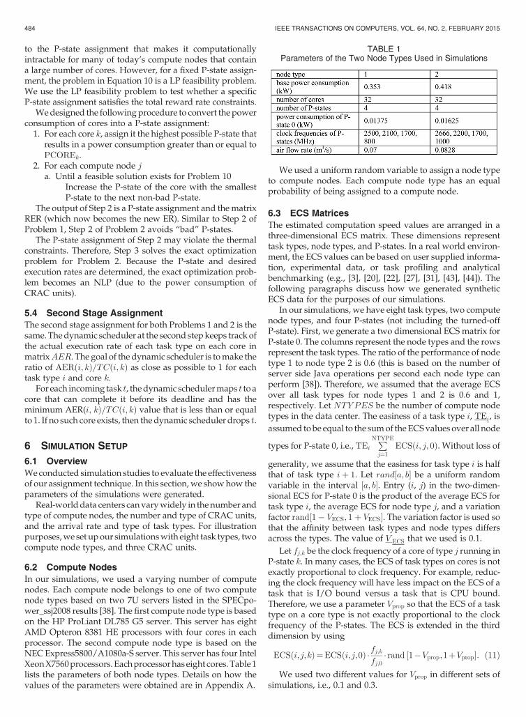
6.2 Compute NodesIn our simulations, we used a varying number of computenodes. Each compute node belongs to one of two computenode types based on two 7U servers listed in the SPECpo-wer_ssj2008 results [38]. The first compute node type is basedon the HP ProLiant DL785 G5 server. This server has eightAMD Opteron 8381 HE processors with four cores in eachprocessor. The second compute node type is based on theNEC Express5800/A1080a-S server. This server has four IntelXeonX7560processors. Eachprocessorhas eight cores. Table 1lists the parameters of both node types. Details on how thevalues of the parameters were obtained are in Appendix A.
We used a uniform random variable to assign a node typeto compute nodes. Each compute node type has an equalprobability of being assigned to a compute node.
6.3 ECS MatricesThe estimated computation speed values are arranged in athree-dimensional ECS matrix. These dimensions representtask types, node types, and P-states. In a real world environ-ment, the ECS values can be based on user supplied informa-tion, experimental data, or task profiling and analyticalbenchmarking (e.g., [3], [20], [22], [27], [31], [43], [44]). Thefollowing paragraphs discuss how we generated syntheticECS data for the purposes of our simulations.
In our simulations, we have eight task types, two computenode types, and four P-states (not including the turned-offP-state). First, we generate a two dimensional ECS matrix forP-state 0. The columns represent the node types and the rowsrepresent the task types. The ratio of the performance of nodetype 1 to node type 2 is 0.6 (this is based on the number ofserver side Java operations per second each node type canperform [38]). Therefore, we assumed that the average ECSover all task types for node types 1 and 2 is 0.6 and 1,respectively. Let be the number of compute nodetypes in the data center. The easiness of a task type , , isassumed to be equal to the sumof the ECSvalues over all node
types for P-state 0, i.e., . Without loss of
generality, we assume that the easiness for task type is halfthat of task type . Let be a uniform randomvariable in the interval . Entry ( , ) in the two-dimen-sional ECS for P-state 0 is the product of the average ECS fortask type , the average ECS for node type , and a variationfactor . The variation factor is used sothat the affinity between task types and node types differsacross the types. The value of that we used is 0.1.
Let be the clock frequency of a core of type running inP-state . In many cases, the ECS of task types on cores is notexactly proportional to clock frequency. For example, reduc-ing the clock frequency will have less impact on the ECS of atask that is I/O bound versus a task that is CPU bound.Therefore, we use a parameter so that the ECS of a tasktype on a core type is not exactly proportional to the clockfrequency of the P-states. The ECS is extended in the thirddimension by using
We used two different values for in different sets ofsimulations, i.e., 0.1 and 0.3.
TABLE 1Parameters of the Two Node Types Used in Simulations
484 IEEE TRANSACTIONS ON COMPUTERS, VOL. 64, NO. 2, FEBRUARY 2015
Using Equation 11 may result in a P-state that has a higherECS value for a specific task type and a specific core type thana lowerP-state. Toprevent this case, if an entry ( , , ) is higherthan entry ( , , ), then we generate a random number
for until it is less than. We start by generating the ECS for P-state 1
then P-state 2 and so on.
6.4 Task TypesThe number of task types in all of our simulations is assumedto be eight. The reward for completing a task of type by itsdeadline is assumed to be equal to the reciprocal of itseasiness, i.e.,
Wealso have conducted simulations to showhowdifferentreward values will affect the performance of our assignmenttechniques (see Section 7.2.5).
Now we show how the values that are used to calculatethe deadline of individual tasks are generated. Letand be theminimumandmaximumECSvalues fortask type over all core types and all P-states except theturned-off P-state. is given by
is given by
The value of is given by
We used Equation 15 to compute because it guaranteesthat there is at least one core type that canmake thedeadline ofa task of type . There is also a chance of generating a task typesuch that some of its tasks’ deadlines can be met by all coretypes running at their lowest frequency.
The last parameter that needs to be generated for a tasktype is its arrival rate, . Let be the ECS obtainedfor a task type if all cores in the data center are used equallyby every task type and all cores are running in P-state 0. Thevalue of is given by
Our goal is to assign arrival rates for task types such thatthe data center can complete all the arriving tasks whenrunning at full capacity (i.e., all cores in P-state 0) but wouldbe oversubscribed if there is a power constraint (i.e., there isnot enough power to run all cores in P-state 0). This is notsimple to achieve. Therefore,weuse to approximatethe arrival rates. In addition, to introduce some randomness inthe assigned arrival rate of task type , we use a parameter,
. Once the arrival rate for a task type is assigned, itremains constant. The arrival rate of task type is given by
The value of that we used is 0.3.
6.5 Cross Interference CoefficientsIn [39], for two compute nodes and , the cross interferencecoefficient, , is the percentage of air recirculated fromcompute node to compute node . Computational FluidDynamics (CFD) simulationswere used in [39] to obtain crossinterference coefficients for a small data center (ten racks withfive compute nodes in each rack, and one CRAC unit). Thetime consumed for a single run of aCFDsimulationwas aboutan hour with a CFD simulation required for each of the 50compute nodes [39]. In our simulations, we use 150 computenodes and three CRAC units. The amount of time to run theCFD simulations for each data center in our simulations isprohibitive. In Appendix B, we show how an LP feasibilityproblem can be used to generate the cross interference coeffi-cients. Our goal is not to propose a method of calculating thecross interference coefficients for a real data center. Rather,our goal is to generate cross interference coefficients forsimulation studies that are based on realistic informationabout the air flows in data centers.
6.6 Power and Thermal ConstraintsTo set a reasonable power constraint in our simulations forProblem 1, we need to find the minimum and maximumpower consumption of the data center. The minimum powerconsumption occurs when all cores in the data center areturned off. The maximum power consumption occurs whenall cores are running in P-state 0. The minimum and maxi-mum power consumption of the data center can be foundusing the NLP problem below solved for the two extremevalues of . The solution for this problemwill provide thepower consumption bounds of the data center. The decisionvariables are the outlet temperatures of CRAC units. Becauseit is an NLP problem, our solution to the problem will notnecessarily provide the global minimum. Therefore, the solu-tions are considered an upper bound of the minimum andmaximum power consumption of the data center.
subject to
Let and be the upper bounds on the minimumandmaximumpower consumption of the data center, respec-tively. Let be a “power multiplier” that takes values in theinterval [0,1]. The powermultiplier allowsus to select a powerconstraint that is between the minimum and the maximumpower consumption bounds. The power constraint, , isgiven by
The redline inlet air temperature was set at 25 Celsius forcompute nodes and 40 Celsius for CRAC units.
6.7 Total Reward ConstraintTo set a reasonable total reward rate constraint for Problem 2,we need to find the maximum possible total reward rate thatoccurs when all cores are running in P-state 0. Let
AL-QAWASMEH ET AL.: POWER AND THERMAL-AWARE WORKLOAD ALLOCATION IN HETEROGENEOUS DATA CENTERS 485
be the average fraction of a core in compute node that is usedto execute task of type . The effective number of cores atcompute node that are used to execute tasks of type , ,is equal . The maximum reward rate can befound using the following LP:
Subject to
1. ,
2. , ,
3. .
6.8 CRAC unitsIn our simulations,we assumed that there are 3 homogeneousCRAC units. The CoP for each CRAC unit is given by Equa-tion 8. The air flow rate of each CRAC unit is set so that thesum of the air flow rates of the compute nodes is equal to thesumof theflow rates of theCRACunits. The layout of the datacenter is given in Fig. 1.
7 SIMULATION RESULTS
7.1 Comparison OverviewOne may choose to run all cores in the data center in P-state 0without considering the power consumption implications.Although this approach is simple andwill result in the highestreward rate, itmayviolate the power constraint and result in alower reward rate per power consumption. We show this inthe next subsection.
We performed simulations for the first-stage assignmentproblem and compared our technique with a technique thatonly considers putting a core in P-state 0 or turning off thecore. The authors in [36] show how the fraction of the“computational resources” at a compute node can be usedto compute the power consumption of a compute node andthe QoS obtained from that compute node. Our techniquessolvedifferent assignmentproblems than the technique in [36]and our techniques consider P-state assignments. We adaptthe technique in [36] by relating the effective number of coresused at a compute node to the reward rate obtained from thatcompute node and the total power consumed at that node asdescribed by Equations 21 and 22. We compare our techni-ques with the one adapted from [36].
The power consumption of compute node is given by
The reward rate for a task of type at compute node isequal to The comparison technique forsolving Problem 1 is given by
Subject to
1. ,
2. , ,
3. ,
4. .
Constraint 1 guarantees that the execution rate for a tasktype is not higher than its arrival rate. The effective number ofcores used at a compute node must not exceed the totalnumber of cores at that compute node. This is guaranteedby Constraint 2. Constraints 3 and 4 are the power andthermal constraints, respectively. The deadline constraintscan be dealt with by setting whenever
Equation 22 is an NLP problem dueto the power consumption of CRAC units. The comparisontechnique for solving Problem 2 is similar to the comparisontechnique for solving Problem 1 except that the objective is tominimize power consumption while guaranteeing that thetotal reward rate does not drop below .
7.2 Results7.2.1 OverviewWe have conducted simulations to compare our techniqueagainst the one described in Equation 22. We illustrate theeffect of the following three parameters on the performance:1) static power consumption of cores, 2) the variation of theECS values from being proportional to the clock frequency ofcores, and 3) the reward and power constraints. Note that thestatic power consumption is part of the total power consump-tion of a core and is different than the base power consumptionof a compute node. The static power consumption is part ofthe second term in Equation 1. The total power consumptionof a compute node is equal to the sum of its base powerconsumption and the sum of the static and dynamic powerconsumption of its cores. The results in this section show thepercentage increase in the reward rate or the percentagedecrease in the power consumption that our techniqueachieves in comparison to the one described in Equation 22.
7.2.2 Random Starting PointsBecause the Step 1 assignments of both Problems 1 and 2 areNLPs, their solutions may be locally optimal. The quality ofthe locally optimal solution is affected by the starting point ofthe NLP optimization. To determine an appropriate numberof starting points to use, we have conducted 20 simulations,each using 100 randomly generated starting points. For eachsimulation, we determined the number of random startingpoints needed to obtain a solution that is within 1% of the bestsolution. The upper limit of a 95% confidence interval of thenumber of solutionswas 11.45, soweused 11 random startingpoints for our simulations and one starting point that is thesolution of Equation 22.
The Problem in Equation 22 is a NLP due to the powerconsumption of the CRAC units. Therefore, the solutions tothe problemsmaybe locally optimal.Abrute force discretizedoptimization of a problem that has three CRAC units,
486 IEEE TRANSACTIONS ON COMPUTERS, VOL. 64, NO. 2, FEBRUARY 2015

150 compute nodes, and eight task types, is computationallyintractable. However, tests on smaller problems, i.e., twoCRAC units, 40 compute nodes, and eight task types, haveshown no improvement. Therefore, we only use a singlestarting point to find the solution to Equation 22.
7.2.3 Main Results for Problems 1 and 2Figs. 6 and 7 show the percentage increase in the reward ratefor Problem 1 and the percentage reduction in power con-sumption for Problem 2 that our technique achieves. Each barin Figs. 6 and 7 represents the average of 20 simulations. Errorbars are added to show a 95% confidence interval around theaverage.
Both figures show that as the static power consumptionof P-state 0 increases, the relative performance of ourtechnique decreases. Because P-state 0 runs at a higher
voltage and frequency, the percentage of dynamic powerconsumption is usually higher than that of the otherP-states. Therefore, the static power as a percentage of theoverall power consumption for the other P-states will behigher compared to that of P-state 0. The static powerconsumption is not related to the frequency, so the higherP-states will have a lower performance (in terms of clockfrequency) to power consumption ratio compared toP-state 0. When the performance to power consumptionratio of P-state 0 is the highest among all the P-states, theassignment technique of Equation 22 will perform as wellas our technique. The static power percentages for all theP-states of each node type are shown in Table 2. The staticpower consumption of the P-states in each node type iscalculated using the static power of P-state 0. For oursimulations, we assumed three different static power con-sumption percentages for P-state 0 (10, 20, and 30%). Referto Appendix A for details about the calculation of the staticpower.
Figs. 6 and 7 also show that the relative performance of ourtechnique increases as increases from 0 to 0.3. For a givencore type, a higher value of gives a higher affinity ofP-states to task types (i.e., some P-states will be better suitedfor specific task types than others). Therefore, more rewardrateperpower consumption canbeobtainedbymatching tasktypes with their better suited P-states.
The reason that our technique achieves higher increase inreward rate for Problem 1 compared to the decrease in powerconsumption for Problem 2 is that there is a lower bound onthe minimum power.
The lower bound occurs when all cores are turned off andall compute nodes are only consuming the base power.However, the minimum reward rate of the data center iszero, which also happens when all cores are turned off.Because the minimum power is greater than zero, Problem2 leaves less opportunity for improvement than Problem 1. Ifwe do not consider the minimum power consumption of thedata center for both our technique and the technique inEquation 22, then percentage power reduction that our tech-nique achieves over the technique in Equation 22 will be onaverage 1.58 times higher on average.
The simple approach of running all cores in the data centerat P-state 0 will result in a violation of the power constraint forProblem 1 and higher power consumption for Problem 2. Forexample, when P-state 0 static power is 10% of its total powerconsumption and is 0.1, the simple approach resulted in aviolation of the power constraint by 42% for Problem 1 and apower consumption of 75% higher than our approach forProblem 2.
Fig. 6. This figure shows the results for Problem 1 (maximizing rewardrate). The average percentage improvement obtained by using the three-step assignment given in Section 5.2 versus the assignment that is basedon [36] (given in Equation 22) is shown. A 95% confidence interval isshown for each average percentage improvement. The static powerconsumption of P-state 0 as a percentage of the total processing corepower consumption is increased from10% to30%.Eachgroupof columnscompares the resultswhen the valueof is 0, 0.1, and0.3. Thenumberof compute nodes, task types, and CRAC units for each simulation is 150,eight, and three, respectively.
Fig. 7. This figure shows the results for Problem 2 (minimizing powerconsumption). The average percentage improvement obtained by usingthe three-step assignment given inSection 5.3 versus the assignment thatis based on [36] (given in Equation 22) is shown. A 95% confidenceinterval is shown for each average percentage improvement. The staticpower consumption of P-state 0 as a percentage of the total processingpower consumption is increased from10% to30%.Eachgroupof columnscompares the results when the value of is 0,0.1, and 0.3. The numberof compute nodes, task types, and CRAC units for each simulation is 150,eight, and three, respectively.
TABLE 2Static Power Consumption of P-States of Cores in Each Node
Type as a Percentage
AL-QAWASMEH ET AL.: POWER AND THERMAL-AWARE WORKLOAD ALLOCATION IN HETEROGENEOUS DATA CENTERS 487
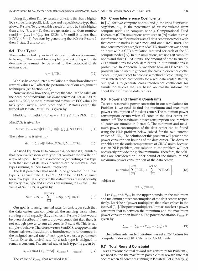
7.2.4 Effect of Power and Reward ConstraintsWe also have conducted simulations to show the effect ofincreasing the power and reward constraints on the perfor-mance of our techniques. For these simulations, the staticpower consumption of P-state 0 was set to 10% of its totalpower consumption and was set to 0.3. These simula-tions are shown in Figs. 8 and 9.
As the power constraint gets tighter (i.e., the powermultiplier value gets lower) the relative performance of ourtechnique improves. This is because when power is scarce,managing it intelligently can lead to substantial performancegains. As the power constraint gets looser, our technique willstart assigning lower P-states to take advantage of the availablepower. Therefore, the performance of our technique will becloser to the performance of the technique in Equation 22 untilthey are both equal when the power multiplier is equal to 1.
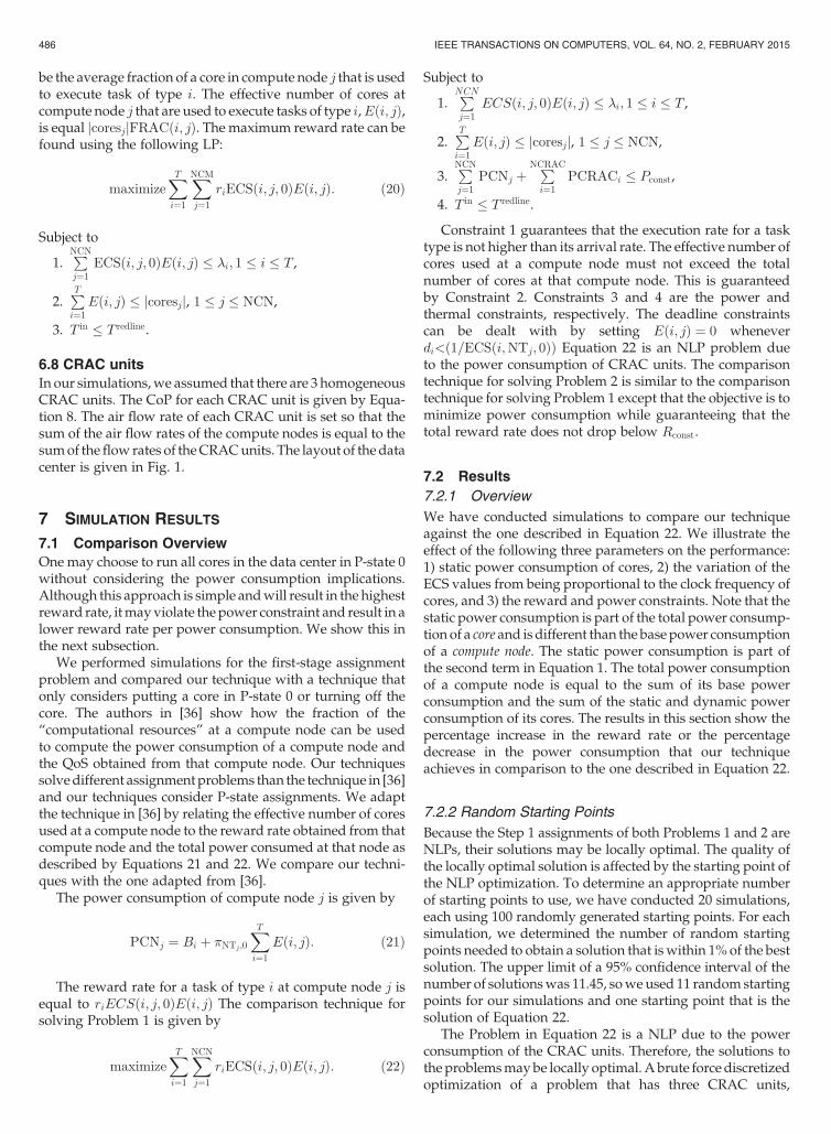
As shown in Fig. 9, when the reward constraint is low, therelative performance of our technique is low. This is becausethere is a lower bound on the minimum power consumptionof the data center. However, as the reward constraint in-creases, the power needed to satisfy the reward rate constraintbecomes higher and more power savings can be obtainedusing our technique. Even when the reward rate constraint isat 90% of themaximumpossible, our technique achieves 8.6%improvement.When the reward rate constraint is 100% of themaximum possible, both our technique and the one in Equa-tion 22will run all cores in the data center at P-state 0 to satisfythe constraint. Therefore, our approach will have no rewardrate improvements.
Figs. 8 and 9 also show the reward rate per power con-sumption ratio for different power and reward rate con-straints. When the power multiplier is low (i.e., tighter powerconstraint) or the reward rate multiplier is low (i.e., looserreward rate constraint) solutions to Problem 1 and Problem 2are bothdriven to consume less power and collect less reward.Because of the minimum power consumption of the datacenter is not zero, the ratio of the reward rate to powerconsumption decreases more with the reduction in rewardrate than it does increase with the reduction in total power
consumption. This explains the low reward rate to powerconsumption ratio when the power multiplier is low or thereward rate multiplier is low.
There are two reasons that cause the ratio of reward rate topower consumption to decline for a higher value of a powerconstraint for Problem 1 or a higher value of a reward rateconstraint for Problem 2. The first reason is that our tech-nique will run the cores at lower P-states that are not powerefficient so that all the power that is available is used (inProblem 1) or the reward rate constraint is satisfied (inProblem 2). The second reason is that our technique willassign tasks of types that have low reward rates because allthe higher reward rate tasks are fully assigned. The simpleapproach of running all cores in the data center at P-state 0will be equivalent to the case where the reward rate con-straint is 100% of the maximum and the case where thepower multiplier is 1. The simple approach will result in areward rate per power consumption ratio equal to 19.43 thatis less than the highest ratio which is equal to 21.6 forProblem 1 (Fig. 8) and 21.4 for Problem 2 (Fig. 9).
7.2.5 Effect of RewardIn all the results discussed previously, the reward of a tasktype was assumed to be equal to the reciprocal of its easiness(see Equation 12).We have conducted two sets of simulationsfor Problem 1 to show the effect of different task type rewardvalues on the performance results of our technique. Thefollowing are the common parameters between both sets ofsimulations (which are identical to those from Fig. 6):
1. The number of task types, CRAC units, and computenodes is eight, three, and 150, respectively.
2. The static power percentage for P-state 0 is 10%.3. The power multiplier is 0.5.4. Each set of simulations has 20 cases.In the first set of simulations, we calculated eight reward
values using Equation 12. The reward value of a task typewasassigned randomly with no replacement from the set of eightreward values. The average increase in reward rate that ourtechnique achieved compared to the one in Equation 22 was
Fig. 8. This figure shows the percentage increase in reward rate that ourapproach achieves over the technique in Equation 22 and the reward rateper power consumption for our technique for Problem 1 (maximizingreward rate). The power multiplier is increased from 0.1 to 1 with a stepof 0.1. The static power of P-state 0 is 10% and is 0.3. Each point inthe figure represents a simulation case for one data center. The number ofcompute nodes, task types, and CRAC units for each simulation is 150,eight, and three, respectively.
Fig. 9. This figure shows the percentage reduction in power consumptionthat our approach achieves over the technique in Equation 22 and thereward rate per power consumption for our technique for Problem 2(minimizing power). The reward rate as a percentage of the maximumpossible reward rate is increases from10% to100%.Thestatic powerofP-state 0 is 10% and is 0.3. Each point in the figure represents asimulation case for one data center. The number of compute nodes, tasktypes, and CRAC units for each simulation is 150, eight, and three,respectively.
488 IEEE TRANSACTIONS ON COMPUTERS, VOL. 64, NO. 2, FEBRUARY 2015

13%. This reward rate increase is less than the reward rateincrease for the same static power (10%) and (0.3) in Fig. 6(in that case it was 18.5%). The reason for this lower rewardrate increase is that whenwe assign reward values randomly,we will have some tasks that have faster average executionrates and havemore reward. Both heuristics (ours and the onebased on Equation 22) execute the easier tasks that have themost reward. Even though our heuristic executes more tasksthan the one based on Equation 22, the difference in totalreward rate is not as large because the extra tasks are moredifficult and have a smaller reward rate. This effect was evenmore pronounced in our second set of simulations were weassigned task types a reward value that was equal to itseasiness (i.e., easier tasks will have more reward).
7.2.6 Scalability AnalysisIn our approach, the step that consumes the most time is Step1.We conducted a scalability analysis for the execution timeofStep 1 for Problem 1 (the execution time for Problem 2 wassimilar to Problem 1). Table 3 shows the execution times inseconds for different numbers of compute nodes. The numberof task types remains fixed at eight task types. In Table 4, wehave increased the number of task types as the number ofcompute nodes was increased. The execution times for eachcase in both Tables 3 and 4 are averaged acrossfive simulationruns. All the simulations were run on a laptop computer witha Core i7 processor running at a clock frequency of 2.8 GHz.The number of CRAC units was fixed at three CRAC units.
Tables 3 and 4 show that the execution time is sensitive toboth the number of task types and the number of computenodes. Recall that the task type arrival rate is a function of thenumber and type of compute nodes (which determines thetotal number of cores) and the number of task types ( ), asshown in Equation 16. As increases, the arrival rate of eachtask type decreases (Equation 16). However, the total work-load remains relatively constant.
Because the calculation of Step 1 is done offline (i.e., theassignment decisions are made before tasks arrive) based onestimated task arrival rates obtained from historical data foreach task type, it is feasible to execute it for a longer timecompared to online techniques. Furthermore, if Step 1 isparallelized (for example, by calculating the solutions tomultiple starting points in parallel), then the time consumedby it can be significantly reduced.
7.2.7 Unexecuted WorkloadBecause of the power constraint in Problem 1 and the reduc-tion of power consumption in Problem 2, a portion of theworkload will not be executed. The task types that are notexecuted are the ones with low reward per power
consumption ratio. In many cases, these task types were thesame for our technique and the technique in Equation 22.However, there are some caseswere thiswas not the case. Thisis because our technique considers higher P-states that mayhave a better reward per power consumption for differenttask type than the technique in Equation 22.
Both our technique and the technique in Equation 22 exe-cute more tasks for Problem 1 compared to Problem 2. This isbecause in Problem 1 the goal is to execute as many tasks aspossible to maximize the reward. However, in Problem 2 thegoal is to minimize the power consumption which will resultin less tasks being executed because we are not concernedwith collecting reward at a rate higher than the reward rateconstraint.
7.2.8 SummaryOur results show an average improvement over the compari-son technique of up to 17% for Problem 1 (maximizingreward) and up to 9% for Problem 2 (minimizing power).Higher percentage increase in reward rate can be achieved fordata centers with tighter power constraints. Because today’sdata centers are large, these improvements can mean hun-dreds of thousands of dollars in additional revenue or powersavings. For example, the average cost of electricity in theU.S.for the industrial sector is [16]. If we achieve 9%power savings in a data center that has an average powerconsumption of 5MW, then that will result in aboutin annual savings.
8 CONCLUSION
In this paper, we study two assignment problems. The firstproblemmaximizes the reward collected for completing tasksby their deadlines with a constraint on the maximum totalpower consumption. The second problem minimizes powerconsumption with a constraint on the minimum reward rate.We show how the P-states can be assigned at the data centerlevel and divide each assignment problem into two stages.Thefirst stage assigns theP-states of cores, thedesirednumberof tasks per unit time allocated to a core, and the outlet CRACtemperatures. The second stage assigns individual tasks asthey arrive at thedata center to cores so that the actual numberof tasks per unit time allocated to a core approaches thedesired number set by the first stage.
We formulate the first-stage assignment as a MINLP.Because theMINLP is not scalable with respect to the numberof cores, we propose a multi-step, scalable assignment tech-nique. At the second stage, we propose a dynamic schedulerto assign tasks entering the data center to cores.
TABLE 3Execution Times for Step 1 of Problem 1 as the Number of
Compute Nodes Varies
Table 4Execution Times for Step 1 of Problem 1 as the Number of
Compute Nodes and the Number of Task Types Vary
AL-QAWASMEH ET AL.: POWER AND THERMAL-AWARE WORKLOAD ALLOCATION IN HETEROGENEOUS DATA CENTERS 489
Inmany data centerswhere static and dynamic core powerconsumptions are considered, P-state 0 is not the P-state withthe highest performance to power consumption ratio. There-fore, using the assignment techniques in this paper will resultin a better total reward over a technique that chooses betweenputting a core in P-state 0 or turning it off.
We conducted simulations to show the effectiveness of ourtechnique over a technique based on [36] which did notconsider multiple P-states. In some cases, our techniqueachieved 17% average improvement for the problem of maxi-mizing reward and 9% average improvement for the problemof minimizing the power consumption. In a large data center,these improvements can mean hundreds of thousands ofdollars in additional revenue from additional productivity(Problem 1) or power savings (Problem 2).
In our work, we assume that there is always enoughmemory to run all the tasks assigned to the cores in a specificcompute node. One way this work can be extended is to takeinto account memory limitations.
ACKNOWLEDGMENTS
The authors thank Mark Oxley and Ryan Friese for theirvaluable comments on this work. This research was sup-ported by the NSF under Grant CNS-0905399, and by theColorado State University George T. Abell Endowment. Apreliminary version of portions of this material appeared inthe Heterogeneity in Computing Workshop 2012.
REFERENCES
[1] AMD Family 10h Server and Workstation Processor Power and ThermalData Sheet. Publication # 43374, Revision 3.19, June 2010.
[2] Z. Abbasi, G. Varsamopoulos, and E.K.S. Gupta, “Thermal AwareServer Provisioning and Workload Distribution for Internet DataCenters,” Proc. 19th ACM Int’l Symp. High Performance DistributedComputing (HPDC’10), pp. 130-141, 2010.
[3] S. Ali, T.D. Braun, H.J. Siegel, A.A. Maciejewski, N. Beck, L. Bölöni,M. Maheswaran, A.I. Reuther, J.P. Robertson, M.D. Theys, andB. Yao, “Characterizing Resource Allocation Heuristics for Hetero-geneous Computing Systems,” Advances in Computers, Parallel, Dis-tributed, and Pervasive Computing, vol. 63, pp. 91-128, 2005.
[4] A.M.Al-Qawasmeh, A. A.Maciejewski, andH. J. Siegel, “Character-izingHeterogeneousComputingEnvinronmentsUsing SingularVal-ue Decomposition,” Proc. 19th Heterogeneity in Computing Workshop(HCW 2010), 24th Int’l Parallel and Distributed Processing Symp., Work-shops and PhD Forum (IPDPSW 2010), pp. 1-9, Apr. 2010.
[5] A.M. Al-Qawasmeh, A.A.Maciejewski, andH.J. Siegel, “Character-izing Task-Machine Affinity in Heterogeneous Computing Envir-onments,” Proc. 20th Heterogeneity in Computing Workshop (HCW2011), 25th Int’l Parallel and Distributed Processing Symp., Workshopsand PhD Forum (IPDPSW 2011), pp. 34-44, Apr. 2011.
[6] A.M. Al-Qawasmeh, A.A. Maciejewski, H. Wang, J. Smith,H.J. Siegel, and J. Potter, “Statistical Measures for Quantifying Taskand Machine Heterogeneities,” J. Supercomputing, Special Issue onAdvances in Parallel and Distributed Computing, vol. 57, no. 1,pp. 34-50, July 2011.
[7] J. Apodaca, D. Young, L. Briceno, J. Smith, S. Pasricha, A.A.Maciejewski, H.J. Siegel, S. Bahirat, B. Khemka, A. Ramirez, andY. Zou, “Stochastically Robust Static Resource Allocation for EnergyMinimization with a Makespan Constraint in a HeterogeneousComputing Environment,” Proc. 9th ACS/IEEE Int’l Conf. ComputerSystems and Applications (AICCSA‘11), p. 10, Dec. 2011.
[8] H. Aydin, R. Melhem, D. Mosse, and P. Mejia-Alvarez, “DynamicandAggressive SchedulingTechniques for Power-AwareReal-TimeSystems,” Proc. 22nd IEEE Real-Time Systems Symp. (RTSS‘01),pp. 95-105, Dec. 2001.
[9] H.Barada, S.M. Sait, andN.Baig,“TaskMatchingandScheduling inHeterogeneous Systems Using Simulated Evolution,” Proc. 10thHeterogeneous Computing Workshop (HCW 2001), 15th IEEE Int’lParallel and Distributed Processing Symp. (IPDPS 2001), pp. 875-882,Apr. 2001.
[10] A. Beloglazov, J. Abawajy, and R. Buyya, “Energy-Aware ResourceAllocation Heuristics for Efficient Management of Data Centers forCloud Computing,” Future Generation Computer Systems, vol. 28,no. 5, pp. 755-768, May 2012.
[11] D. Brown and C. Reams, “Toward Energy-Efficient Computing,”Communications of the ACM, vol. 53, no. 3, p. 14, Mar. 2010.
[12] J.A. Butts andG.S. Sohi, “AStatic PowerModel forArchitects,”Proc.33rd Ann. ACM/IEEE Int’l Symp. Microarchitecture (MICRO 33),pp. 191-201, Dec. 2000.
[13] K. W. Cameron, R. Ge, and X. Feng, “High-Performance, Power-AwareDistributedComputing for Scientific Applications,”Comput-er, vol. 26, no. 11, pp. 40-47, Nov. 2005.
[14] J. Choi, S. Govindan, J. Jeong, B. Urgaonkar, andA. Sivasubramaniam, “Power Consumption Prediction and Power-Aware Packing in Consolidated Environments,” IEEE Trans.Computers, vol. 59, no. 12, pp. 1640-1654, Dec. 2010.
[15] M.K. Dhodhi, I. Ahmad, and A. Yatama, “An Integrated Techniquefor TaskMatching and Scheduling onto Distributed HeterogeneousComputing Systems,” Parallel and Distributed Computing, vol. 62,no. 9, pp. 1338-1361, Sep. 2002.
[16] Energy Information Administration. http://www.eia.gov/electrici-ty/data.cfm, last accessed, 2012.
[17] E. N. Elnozahy, M. Kistler, and R. Rajamony, “Energy-EfficientServer Clusters,” Proc. Second Int’l Workshop Power-Aware ComputerSystems, pp. 179-197, 2002.
[18] Environmental Protection Agency. Report to Congress on Serverand Data Center Energy Efficiency, http://www.energystar.gov/ia/partners/prod_development/downloads/EPA_Datacenter_Report_Congress_Final1.pdf, Last accessed, 2011.
[19] D. Filani, J. He, S. Gao, M. Rajappa, A. Kumar, P. Shah, andR. Nagappan, “Dynamic Data Center Power Management: Trends,Issues,andSolutions,” IntelTechnologyJ.,vol.12,no.1,pp.59-67,2008.
[20] R.F. Freund andH.J. Siegel, “Heterogeneous Processing,”Computer,vol. 26, pp. 13-17, June 1993.
[21] S.K. Grag, C.S. Yeo, A. Anadsivam, and R. Buyya, “Environment-Conscious Scheduling of HPC Applications on Distributed Cloud-Oriented Data Centers,” Parallel and Distributed Computing, vol. 71,no. 6, pp. 732-749, June 2011.
[22] A. Ghafoor and J. Yang, “A Distributed Heterogeneous Supercom-puting Management System,” Computer, vol. 26, no. 6, pp. 78-86,June 1993.
[23] Hewlett-Packard Corporation, Intel Corporation, Microsoft Corpo-ration, Phoenix Technologies Ltd., and Toshiba Corporation Std.(Apr. 2010). Advanced Configuration and Power Interface Specification,Rev. 4.0a, http://www.acpi.info/DOWNLOADS/ACPIspec40a.pdf, last accessed, 2012.
[24] J.-W. Jang, M. Jeon, H.-S. Kim, H. Jo, J.-S. Kim, and S. Maeng,“Energy Reductions in Consolidated Servers through Memory-AwareVirtualMachine Scheduling,” IEEE Trans. Computers, vol. 60,no. 4, Apr. 2011.
[25] M. Kafil and I. Ahmad, “Optimal Task Assignment in Heteroge-neous Distributed Computing Systems,” IEEE Concurrency, vol. 6,no. 3, pp. 42-51, July 1998.
[26] X. Kang, H. Zhang, G. Jiang, H. Chen, X. Meng, and K. Yoshihira,“Understanding Internet Video Sharing Site Workload: A Viewfrom Data Center Design,” J. Visual Comm. Image Representation,vol. 21, no. 2, pp. 129-138, Feb. 2010.
[27] A. Khokhar, V.K. Prasanna, M.E. Shaaban, and C. Wang, “Hetero-geneous Computing: Challenges and Opportunities,” Computer,vol. 26, no. 6, pp. 18-27, June 1993.
[28] J.-K. Kim, H.J. Siegel, A.A. Maciejewski, and R. Eigenmann, “Dy-namic ResourceManagement in Energy ConstrainedHeterogeneousComputing SystemsUsing Voltage Scalling,” IEEE Trans. Parallel andDistributed Systems, Special Issue on Power-Aware Parallel and Distribut-ed Systems, vol. 19, no. 11, pp. 1445-1457, Nov. 2008.
[29] Y. Lin and L. He, “Dual-VDD Interconnect with Chip-Level TimeSlackAllocation for FPGAPowerReduction,” IEEETrans. Computer-Aided Design of Integrated Circuits and Systems, vol. 25, no. 10,pp. 2023-2034, Oct. 2006.
[30] J.R. Lorch and A.J. Smith, “Improving Voltage Scaling AlgorithmsWith PACE,” ACM SIGMETRICS Performance Evaluation Rev.,vol. 29, no. 1, pp. 50-61, June 2001.
490 IEEE TRANSACTIONS ON COMPUTERS, VOL. 64, NO. 2, FEBRUARY 2015
[31] M. Maheswaran, T.D. Braun, and H.J. Siegel, “Heterogeneous Dis-tributed Computing,” Encyclopedia of Electrical and Electronics Engi-neering. New York: John Wiley & Sons, vol. 8, pp. 679-690, 1999.
[32] J. Moore, J. Chase, P. Ranganathan, and R. Sharma, “MakingScheduling ‘Cool’: Temperature-Aware Workload Placement inData Centers,” Proc. USENIX Ann. Technical Conf. (ATEC‘05),10 pp., 2005.
[33] T. Mukherjee, G. Varsamopoulos, S.K.S. Gupta, and S. Rungta,“Measurement-Based Power Profiling of Data Center Equipment,”Proc. IEEE Int’l Conf. Cluster Computing, pp. 476-477, Sep. 2007.
[34] E. Pakbaznia, M. Ghasemazar, and M. Pedram, “Temperature-Aware Dynamic Resource Provisioning in a Power-Optimized Da-tacenter,” Proc. Conf. Design, Automation and Test in Europe 2010,pp. 124-129, 2010.
[35] V. Pallipadi andA. Starikovsky, “TheOn-DemandGovernor,” Proc.2006 Linux Symp., pp. 215-229, 2006.
[36] L. Parolini,N. Tolia, B. Sinopoli, andB.H.Krogh, “ACyber-PhysicalSystems Approach to Energy Management in Data Centers,” Proc.1st ACM/IEEE Int’l Conf. Cyber-Physical Systems, pp. 168-177, 2010.
[37] H. Singh andA. Youssef, “Mapping and SchedulingHeterogeneousTask Graphs using Genetic Algorithms,” Proc. 5th IEEE Heteroge-neous Computing Workshop (HCW‘96), pp. 86-97, 1996.
[38] Standard Performance Evaluation Corporation (SPEC). SPECpower_ssj2008, http://www.spec.org/power_ssj2008, last accessed, 2011.
[39] Q. Tang, T. Mukherjee, S.K.S. Gupta, and P. Cayton, “Sensor-BasedFast Thermal Evaluation Model for Energy Efficient High-Perfor-mance Datacenters,” Proc. 4th Int’l Conf. Intelligent Sensing andInformation Processing (ICISIP 2006), pp. 203-208, Dec. 2006.
[40] N. Tolia, Z. Wang, P. Ranganathan, C. Bash, and M. Marwah,“Unified Thermal and Power Management in Server Enclosures,”Proc. ASME/Pacific Rim Technical Conf. Exhibition on Packaging andIntegration of Electronic and Photonic Systems, MEMS, and NEMS(InterPACK), 10 pp., July 2009.
[41] C. Xian, Y.-H. Lu, and Z. Li, “Dynamic Voltage Scaling for Multi-tasking Real-Time Systems with Uncertain Execution Time,” IEEETrans. Computer-Aided Design of Integrated Circuits and Systems,vol. 27, no. 8, pp. 1467-1478, Aug. 2008.
[42] D. Xu, K. Nahrstedt, and D. Wichadakul, “QoS and Contention-AwareMulti-ResourceReservation,”ClusterComputing, vol. 4, no. 2,pp. 95-107, Apr. 2001.
[43] J. Yang, I. Ahmad, and A. Ghafoor, “Estimation of Execution Timeson Heterogeneous Supercomputer Architectures,” Proc. Int’l Conf.Parallel Processing, vol. 1, pp. 219-225, Aug. 1993.
[44] J. Yang, A. Khokhar, S. Sheikh, and A. Ghafoor, “Estimating Execu-tion Time for Parallel Tasks in Heterogeneous Processing (HP)Environment,” Proc. Heterogeneous Computing Workshop, pp. 23-28,Apr. 1994.
[45] B.D. Young, J. Apodaca, L.D. Briceño, J. Smith, S. Pasricha, A.A.Maciejewski, H.J. Siegel, B. Khemka, S. Bahirat, A. Ramirez, andY. Zou, “Deadline and Energy Constrained Dynamic ResourceAllocation in a Heterogeneous Computing Environment,” J. Super-computing, vol. 63, no. 2, pp. 326-347, Feb. 2013.
[46] H. Yu, B. Veeravalli, and Y. Ha, “Dynamic Scheduling of Imprecise-Computation Tasks in Maximizing QoS under Energy Constraintsfor Embedded Systems,” Proc. 2008 Asia and South Pacific DesignAutomation Conf. (ASPDAC‘08), pp. 452-455, Mar. 2008.
Abdulla M. Al-Qawasmeh received the BSdegree in computer science and informationsystems from Jordan University of Science andTechnology, Irbid, Jordan, in 2005, theMSdegreein computer science from the University ofHoustonClear Lake, in 2008, and the PhD degreein computer engineering from Colorado StateUniversity. He currently holds the position of se-nior software developer at Service Logix and LeadSoftwareDeveloper at step2compliance.Hisworkis focused on Web and cloud-based applications.
His research interests include robust, power, and energy-efficient sched-uling techniques in heterogeneous computing systems and data centersand the characterization of heterogeneous computing systems.
Sudeep Pasricha (M’02) received the BE degreein electronics and communication engineeringfrom Delhi Institute of Technology, Delhi, India,in 2000, and the MS and the PhD degrees incomputer science from the University of Califor-nia, Irvine, in 2005 and 2008, respectively. He iscurrently an assistant professor of Electrical andComputer Engineering at Colorado State Univer-sity, Fort Collins, with a joint appointment in theDepartment of Computer Science. His researchinterests are in the areas of energy efficiency and
fault tolerant design for high performance computing, embeddedsystems,andmobile computing. He is currently an advisory board member of ACMSIGDA, information director of the ACM Transactions on Design Automa-tion of Electronic Systems (TODAES), editor of the ACM SIGDA E-news,organizing committee member of the NOCS, RTCSA, AICCSA, andICECS conferences and ICCAD CADathalon, and technical programcommittee member of the DAC, DATE, CODES+ISSS, ISQED, NOCS,NoCArc, VLSI Design, and GLSVLSI conferences and the SIGDA DACPhD Forum. He holds an affiliate faculty member position at the Center forEmbeddedComputer Systems,University of California, Irvine.Hewas therecipient of theAFOSRYoung InvestigatorAward in 2012, andBestPaperAwards at the IEEE AICCSA 2011, IEEE ISQED 2010, and ACM/IEEEASPDAC 2006 conferences.
Anthony A. Maciejewski received the BSEE,MS, and PhD degrees from The Ohio StateUniversity, in 1982, 1984, and 1987, respectively.From 1988 to 2001, he was a professor of Electri-cal and Computer Engineering at Purdue Univer-sity, West Lafayette. He is currently a professorand head of the Department of Electrical andComputer Engineering at Colorado State Univer-sity. He is a fellow of the IEEE, with researchinterests that include robotics and high perfor-mance computing. His complete vita is available
at: http://www.engr.colostate.edu/~aam.
Howard Jay Siegel received the BS degree fromthe Massachusetts Institute of Technology (MIT),and the MA, MSE, and PhD degrees from Prince-ton University. He was appointed the Abell En-dowed chair distinguished professor of Electricaland Computer Engineering at Colorado StateUniversity (CSU) in 2001, where he is also aprofessor of computer science. From 1976 to2001, he was a professor at Purdue University.He is a fellow of the IEEE and a fellow of the ACM.He has coauthored over 400 technical papers. His
research interests include robust computing systems, resource allocationin computing systems, heterogeneous parallel and distributed computingand communications, parallel algorithms, and parallel machine intercon-nection networks.Hewasa co-editor-in-chief of the Journal of Parallel andDistributed Computing, and was on the Editorial Boards of both the IEEETransactions on Parallel and Distributed Systems and the IEEE Transac-tions on Computers. He has been an international keynote speaker andtutorial lecturer and has consulted for industry and government. Home-page: www.engr.colostate.edu/~hj.
▽ For more information on this or any other computing topic,please visit our Digital Library at www.computer.org/publications/dlib.
AL-QAWASMEH ET AL.: POWER AND THERMAL-AWARE WORKLOAD ALLOCATION IN HETEROGENEOUS DATA CENTERS 491