Embed Size (px)
Citation preview

IEEE TRANSACTIONS ON COMPUTER-AIDED DESIGN OF INTEGRATED CIRCUITS AND SYSTEMS 1
PAGURUS: Low-Overhead Dynamic InformationFlow Tracking on Loosely Coupled Accelerators
Luca Piccolboni, Student Member, IEEE, Giuseppe Di Guglielmo, Member, IEEE,and Luca P. Carloni, Fellow, IEEE
Abstract—Software-based attacks exploit bugs or vulnerabili-ties to get unauthorized access or leak confidential information.Dynamic information flow tracking (DIFT) is a security techniqueto track spurious information flows and provide strong securityguarantees against such attacks. To secure heterogeneous systems,the spurious information flows must be tracked through all theircomponents, including processors, accelerators (i.e., application-specific hardware components) and memories. We present PAGU-RUS, a flexible methodology to design a low-overhead shell circuitthat adds DIFT support to accelerators. The shell uses a coarse-grain DIFT approach, thus not requiring to make modificationsto the accelerator’s implementation. We analyze the performanceand area overhead of the DIFT shell on FPGAs and we propose ametric, called information leakage, to measure its security guaran-tees. We perform a design-space exploration to show that we cansynthesize accelerators with different characteristics in terms ofperformance, cost and security guarantees. We also present a casestudy where we use the DIFT shell to secure an accelerator run-ning on a embedded platform with a DIFT-enhanced RISC-V core.
Index Terms—Hardware Accelerators, Dynamic Taint Analysis,Dynamic Information Flow Tracking, Software Attacks, Security.
I. INTRODUCTION
HETEROGENEOUS systems-on-chip (SoCs) include mul-tiple processor cores and application-specific hardware
components, known as hardware accelerators, to reduce powerconsumption and increase performance [1]–[4]. Several accel-erators and accelerator-rich architectures have been developedfor different applications, including neural networks [5], [6],database processing [7], [8], graph processing [9], [10], andbiomedical applications [11]. There exist two main models ofaccelerators [12]. Tightly coupled accelerators are embeddedwithin the processor cores as application-specific functionalunits [13]. They are well-suited for fine-grain computations onsmall data sets. They require to extend the instruction set archi-tecture of the processor cores to include special instructions andmanage their execution. Loosely coupled accelerators, instead,reside outside the processor cores. They typically achieve highspeed-ups with coarse-grain computations on big data sets [14].They are called by software applications through device drivers.
Software-based attacks can exploit security vulnerabilities orbugs in software applications, e.g., buffer overflows and formatstrings, to obtain unauthorized control of applications, inject
The authors are within the Department of Computer Science, ColumbiaUniversity, New York, 10027, NY, USA. Emails: [email protected],[email protected], [email protected]. This article was presentedin the International Conference on Hardware/Software Codesign and SystemSynthesis (CODES+ISSS) 2018 and appears as part of the ESWEEK-TCADspecial issue. Accepted July 2, 2018. DOI: 10.1109/TCAD.2018.2857321
malicious code, etc. [15]. Dynamic information flow tracking(DIFT), also known as dynamic taint analysis in the literature,has been proposed as a promising security technique to protectsystems against software attacks [16], [17]. DIFT is based onthe observations that (1) it is impossible to prevent the injectionof untrustworthy data in software applications (e.g., data comingfrom software users), and (2) it is very difficult to cover all thepossible exploits that use such data. It is better to monitor, i.e.,track, the suspicious data flows during the application executionto ensure that they are not exploited and do not cause a securityviolation. In such a protection scheme, the data flows from theuntrustworthy sources are marked as spurious. A security policyimposes what the system is allowed to do with spurious data.For example, a policy can enforce that spurious data values arenever used as pointers, thus avoiding buffer-overflow attacks.
Several implementations of DIFT have been proposed inthe literature. DIFT has been implemented in hardware [16],[18]–[20] as well as software [21], [22]. DIFT has been shownto be effective in protecting systems against several software-based attacks, including leakage of information [23] and codeinjection [24]. DIFT is now implemented on different types ofarchitectures [19], [25], including smartphones [23], [26]. Mostof the approaches on hardware-based DIFT focused only onsecuring processor cores and the associated logic, i.e., tightlycoupled accelerators, memories and communication channels.Loosely coupled accelerators, however, have been shown to bevulnerable to attacks [27], [28] and to date there have been onlytwo works [29], [30] on DIFT considering such accelerators.We propose PAGURUS as a methodology to extend the supportof DIFT to loosely coupled accelerators in heterogeneous SoCs.
Contributions. We make the following contributions:
(1) we present PAGURUS, a flexible methodology to designa low-overhead DIFT shell that secures loosely coupledaccelerators; a shell is a hardware circuit whose design isindependent from the design of the accelerators, thus sim-plifying the integration of DIFT in heterogeneous SoCs;we analyze the performance and cost overhead of the shellby synthesizing and running it on FPGAs: the shell has alow impact on execution time and area of the accelerators;
(2) we define the metric of information leakage for acceler-ators to quantitatively measure the security of the DIFTshell: we show that, for any given accelerator, it is possibleto find the minimum number of tags (required by DIFT)so that no information leakage is possible; we also showthat few tags interleaved in the accelerators data are oftensufficient to guarantee the absence of information leakage;

IEEE TRANSACTIONS ON COMPUTER-AIDED DESIGN OF INTEGRATED CIRCUITS AND SYSTEMS 2
Fig. 1. Example of a simple stack-based buffer-overflow attack.
(3) we perform a design-space exploration where we considerperformance, cost and information leakage as optimizationgoals for the accelerators design: this study shows how tostrengthen the security of hardware-accelerated applica-tions in exchange of lower performance and higher cost;
(4) we present a case study where the DIFT shell has beenused to protect an accelerator integrated on a embeddedSoC [31] we extended with DIFT: this shows why a holis-tic DIFT approach is necessary for heterogeneous SoCs.
II. PRELIMINARIES
This section provides the background. We first describe howDIFT prevents a buffer-overflow attack in practice. Then, wepresent the architecture of the SoCs and accelerators we target.Finally, we discuss our assumptions and the attack model.
A. Dynamic Information Flow Tracking (DIFT)
DIFT is a security technique implemented either in hardwareor software to prevent software-based attacks [16], e.g., bufferoverflows. It has been also used, for instance, to avoid leakageof information [23] and secure Web applications [32]. The keyidea is to use tags to mark as spurious the data generated byuntrustworthy channels, e.g., the input provided by the user tothe application. DIFT decouples the concepts of policy (what todo) and mechanism (how to do it). The security policy defineswhich are the untrustworthy channels and the restrictions toapply on using the data marked as spurious. The mechanismensures that the untrustworthy data are marked as spurious andthe tags are propagated in the rest of the system. The presenceof tags is transparent to both software users and programmers.
Example II.1. Consider the stack-based buffer-overflow attackof Fig. 1. While there are other ways to prevent such attack,e.g., non-executable stack, this simple example illustrates apossible application of DIFT. If the user specifies a number ofiterations num higher than 10, then the function pointer funccan be overwritten. In this case, another function (foo) can beexecuted (see the stack reported on the right) instead of the oneintended (bar) in a normal execution (stack on the left). Thefigure reports the commands used to run the program in thetwo cases. DIFT can prevent this kind of attacks by markingthe input of the program (argv) as spurious and by enforcinga policy to avoid using spurious data as pointers. When suchviolations are detected the processor raises an exception.
Fig. 2. Architecture of the tile-based systems-on-chip targeted in this work.
Several implementations of DIFT have been proposed inthe state of the art, as reported in Section IX. Most of theseimplementations target only processor cores, rather than entireSoCs. Among them, two schemes can be used to manage thetags [29]. With the coupled scheme, the tag is stored physicallywith its associated data (same address), i.e., the memory wordis extended to accommodate the tag. Thus, registers, cachesand communication channels are also extended [18]. With thedecoupled scheme, instead, the tags are stored separately fromthe data (different addresses). Typically, the tags are stored ina protected region in memory [19]. In our case, as we move toSoCs, we define a variation of the decoupled scheme where thetags are interleaved with the data. The tags have the same bitwidth of a memory word. They are inserted by the operatingsystem and the software programmers remain unaware of theirpresence. With respect to a coupled scheme, an interleavedscheme allows designers to analyze the effect of changing thetag offset, i.e., the number of words between two consecutivetags in memory. This affects the security guarantees as wellas the performance and cost of the accelerators (Section V).In addition, this scheme does not require a major modificationof the underlying architecture to accommodate the tags. Thus,in this paper, we focus mainly on such interleaved scheme. Toshow the flexibility of our design methodology, however, wepresent the case study of an embedded platform that has beenextended with DIFT by using a coupled scheme (Section VII).
B. Systems-on-Chip (SoCs) and Accelerators
System-on-Chip Architecture. We target a tile-based archi-tecture [1] as the one shown in Fig. 2. Each tile implements aprocessor core (e.g., SPARC V8, RISC-V), a loosely coupledaccelerator, or some accessory functionality such as a memorycontroller. We assume that the processor core supports DIFT asdescribed, for example, in [16]. We aim at extending DIFT toloosely coupled accelerators by leveraging prior works on pro-cessor cores. The components in our target SoC communicateby means of a network-on-chip or a bus. The accelerators aremanaged by the operating system (Linux) trough device drivers.
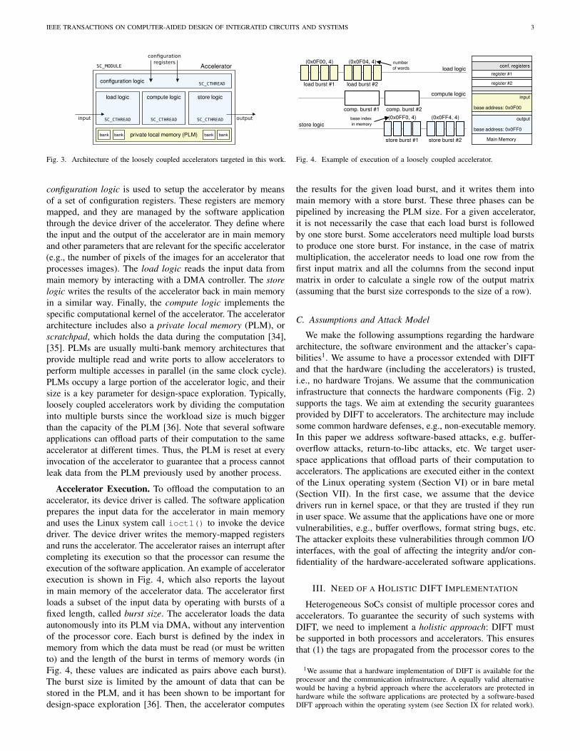
Accelerator Architecture. This paper focuses on looselycoupled accelerators that have an architecture similar to theone reported in [14]. We designed our accelerators in SystemC,an IEEE-standard object-oriented programming language basedon C++ [33]. Fig. 3 shows the architecture, which is commonacross all the accelerators we have implemented. An acceleratoris specified as a SystemC module (i.e., SC_MODULE), and thelogic is divided into four components (i.e., SC_CTHREAD). The
IEEE TRANSACTIONS ON COMPUTER-AIDED DESIGN OF INTEGRATED CIRCUITS AND SYSTEMS 3
Fig. 3. Architecture of the loosely coupled accelerators targeted in this work.
configuration logic is used to setup the accelerator by meansof a set of configuration registers. These registers are memorymapped, and they are managed by the software applicationthrough the device driver of the accelerator. They define wherethe input and the output of the accelerator are in main memoryand other parameters that are relevant for the specific accelerator(e.g., the number of pixels of the images for an accelerator thatprocesses images). The load logic reads the input data frommain memory by interacting with a DMA controller. The storelogic writes the results of the accelerator back in main memoryin a similar way. Finally, the compute logic implements thespecific computational kernel of the accelerator. The acceleratorarchitecture includes also a private local memory (PLM), orscratchpad, which holds the data during the computation [34],[35]. PLMs are usually multi-bank memory architectures thatprovide multiple read and write ports to allow accelerators toperform multiple accesses in parallel (in the same clock cycle).PLMs occupy a large portion of the accelerator logic, and theirsize is a key parameter for design-space exploration. Typically,loosely coupled accelerators work by dividing the computationinto multiple bursts since the workload size is much biggerthan the capacity of the PLM [36]. Note that several softwareapplications can offload parts of their computation to the sameaccelerator at different times. Thus, the PLM is reset at everyinvocation of the accelerator to guarantee that a process cannotleak data from the PLM previously used by another process.
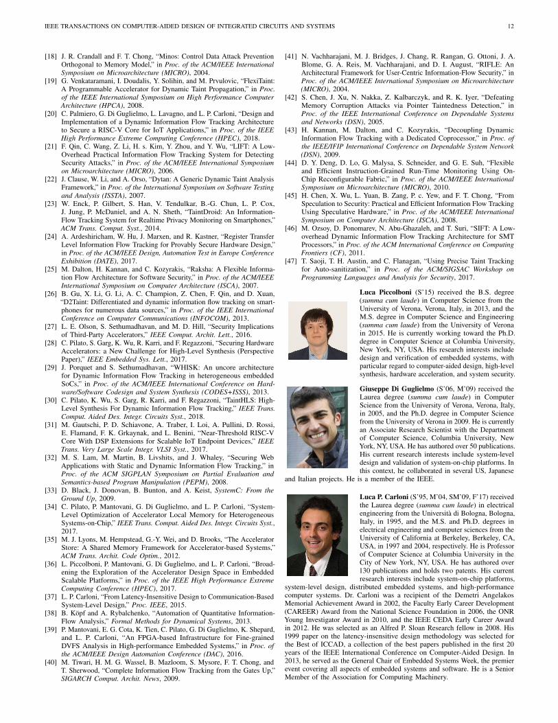
Accelerator Execution. To offload the computation to anaccelerator, its device driver is called. The software applicationprepares the input data for the accelerator in main memoryand uses the Linux system call ioctl() to invoke the devicedriver. The device driver writes the memory-mapped registersand runs the accelerator. The accelerator raises an interrupt aftercompleting its execution so that the processor can resume theexecution of the software application. An example of acceleratorexecution is shown in Fig. 4, which also reports the layoutin main memory of the accelerator data. The accelerator firstloads a subset of the input data by operating with bursts of afixed length, called burst size. The accelerator loads the dataautonomously into its PLM via DMA, without any interventionof the processor core. Each burst is defined by the index inmemory from which the data must be read (or must be writtento) and the length of the burst in terms of memory words (inFig. 4, these values are indicated as pairs above each burst).The burst size is limited by the amount of data that can bestored in the PLM, and it has been shown to be important fordesign-space exploration [36]. Then, the accelerator computes
Fig. 4. Example of execution of a loosely coupled accelerator.
the results for the given load burst, and it writes them intomain memory with a store burst. These three phases can bepipelined by increasing the PLM size. For a given accelerator,it is not necessarily the case that each load burst is followedby one store burst. Some accelerators need multiple load burststo produce one store burst. For instance, in the case of matrixmultiplication, the accelerator needs to load one row from thefirst input matrix and all the columns from the second inputmatrix in order to calculate a single row of the output matrix(assuming that the burst size corresponds to the size of a row).
C. Assumptions and Attack Model
We make the following assumptions regarding the hardwarearchitecture, the software environment and the attacker’s capa-bilities1. We assume to have a processor extended with DIFTand that the hardware (including the accelerators) is trusted,i.e., no hardware Trojans. We assume that the communicationinfrastructure that connects the hardware components (Fig. 2)supports the tags. We aim at extending the security guaranteesprovided by DIFT to accelerators. The architecture may includesome common hardware defenses, e.g., non-executable memory.In this paper we address software-based attacks, e.g. buffer-overflow attacks, return-to-libc attacks, etc. We target user-space applications that offload parts of their computation toaccelerators. The applications are executed either in the contextof the Linux operating system (Section VI) or in bare metal(Section VII). In the first case, we assume that the devicedrivers run in kernel space, or that they are trusted if they runin user space. We assume that the applications have one or morevulnerabilities, e.g., buffer overflows, format string bugs, etc.The attacker exploits these vulnerabilities through common I/Ointerfaces, with the goal of affecting the integrity and/or con-fidentiality of the hardware-accelerated software applications.
III. NEED OF A HOLISTIC DIFT IMPLEMENTATION
Heterogeneous SoCs consist of multiple processor cores andaccelerators. To guarantee the security of such systems withDIFT, we need to implement a holistic approach: DIFT mustbe supported in both processors and accelerators. This ensuresthat (1) the tags are propagated from the processor cores to the
1We assume that a hardware implementation of DIFT is available for theprocessor and the communication infrastructure. A equally valid alternativewould be having a hybrid approach where the accelerators are protected inhardware while the software applications are protected by a software-basedDIFT approach within the operating system (see Section IX for related work).

IEEE TRANSACTIONS ON COMPUTER-AIDED DESIGN OF INTEGRATED CIRCUITS AND SYSTEMS 4
Fig. 5. Example of leakage of information if gray is executed in hardware.
accelerators and vice versa, and (2) the policies are enforced(i.e., the tags are checked) in both processors and accelerators.
Example III.1. Consider the code reported in Fig. 5 that canbe used, for example, in a video-surveillance system. Supposethat ref contains a face image that is compared with the imagepassed through argv. We want to enforce a DIFT policy thatensures that ref cannot be leaked for any reason. Before thecomparison, ref is converted to the same format of the inputimage, e.g., from RGB to grayscale. The function for the con-version is initially implemented in software (gray_software).The processor, which supports DIFT, guarantees that when thisimage is manipulated it is properly tagged. In other words, thetags are propagated and no leaks are possible. Suppose that theconversion is now implemented with an equivalent acceleratorto improve performance (gray_hardware). If the acceleratoris not extended with DIFT, ref is vulnerable to leaks.
IV. DIFT SHELL FOR ACCELERATORS
We designed the DIFT shell to be double decoupled withrespect to the accelerator, and to be flexible. In this section,we first discuss the shell architecture and how it encapsulatesthe accelerator. Then, we discuss such design choices.
A. Implementation of the DIFT Shell
Shell Architecture. We designed the DIFT shell in SystemCwith an architecture similar to the accelerators. Fig. 6 showshow the shell encapsulates the accelerator and distinguishes thedata flows (black solid arrows) from the tag flows (red dashedarrows). The logic is divided into three main components. Theconfiguration logic (configuration shell in Fig. 6 to distinguishit from the configuration logic of the accelerator of Fig. 3) setsup the shell through a set of configuration registers. The shellhas 2×N+2 memory-mapped registers, where N is the numberof registers of the accelerator. Each register of the acceleratoris tagged to ensure that it cannot be easily compromised byan attacker since it can contain sensitive information such asthe addresses in main memory where the inputs and outputsof the accelerator reside. Note that the registers containing thetags are not visible to the software applications and they aremanaged by the device driver. We have also two additionalconfiguration registers. The register src_tag is used to specifythe value of the tags interleaved in the input of the acceleratorand in the configuration registers. The register dst_tag has
Fig. 6. Architecture of the DIFT shell.
the value of the tags to be interleaved in the output of theaccelerator. The values of these two registers are not visibleto the software applications. They are managed by the devicedriver of the accelerator. In particular, these values are passedfrom the processor when the device driver is called. In this waythe tags can be propagated similarly to the case in which theaccelerator functionality is executed in software. This is a formof coarse-grain DIFT, where the output tags of the acceleratorsare determined solely on the basis of the input tags2. There areother two components in the shell of Fig. 6. The load logic(load shell) receives the read requests of the accelerator and itmodifies them to consider the tags, i.e., the shell modifies thebase address in memory and the length of the requests to includethe tags if necessary. Then, it passes the values to the acceleratorwhile checking that the tag values interleaved with input data inmain memory match the value specified in src_tag. In case ofmismatch, it immediately stops the execution of the accelerator.The store logic (store shell) intercepts the write requests ofthe accelerator in a similar way and writes the results of theaccelerator by interleaving the tags with the value in dst_tag.
Tag Interleaving. We use an interleaved scheme to handlethe tags (Section II-A): the tags are interleaved in memory witha fixed tag offset. However, interleaving the tags uniformly inmemory by starting always from the same location is not secure.An attacker could infer the locations of the tags, for instanceby executing the accelerator repeatedly. The attacker couldthen replace the input of the accelerator with malicious data byskipping the tag locations. Therefore, in our implementation ofthe DIFT shell, we keep a fixed distance (in words) betweentwo consecutive tags in memory, but we randomize the locationof the first tag interleaved in the input data at every executionof the accelerator to make it not predictable. The DIFT shellneeds to know the offset of the first tag embedded in the inputin order to check the tags and pass only the data values to theaccelerator. To do that, we add another configuration register tothe shell of Fig. 6. The location of the first tag is generated witha pseudo-random number generator. We chose to use a singletag value for the input (src_tag) and a single tag value for theoutput (dst_tag) of the accelerator. However, (1) the patternwith which the tags are interleaved in the input and output of theaccelerator and (2) the number of different values for the tagscan be customized to offer stronger security guarantees without
2In Section VIII we compare coarse-grain and fine-grain DIFT approaches.

IEEE TRANSACTIONS ON COMPUTER-AIDED DESIGN OF INTEGRATED CIRCUITS AND SYSTEMS 5
Fig. 7. Example of execution of the DIFT shell.
requiring any modification to the accelerator implementation.Alternatively, it is possible to use data-dependent tags insteadof a randomized approach, i.e., the values of src_tag anddst_tag can be calculated by applying a crypto hash functionto the inputs and outputs of a specific accelerator execution.
Shell Execution. Fig. 7 shows an example of execution ofthe DIFT shell encapsulating an accelerator. We consider thecase where the tag offset is equal to one, i.e., the size of theinput and output of the accelerator is doubled to add to eachvalue a tag in the next memory location. This correspondsto the case where we have the maximum number of tags inmemory. The load requests of the accelerator consist of twomemory words. The shell modifies such requests by doublingthe amount of data to include the tags. While doing so, theshell verifies that the tags from the main memory contain thevalue specified in src_tag. Similarly, the store requests fromthe accelerator (two memory words) are modified to interleavethe tags with the value in dst_tag, thus marking the outputs.
B. Adaptability of the DIFT Shell
Double Decoupling. Inspired by the principles of latency-insensitive design [37], we designed the DIFT shell to be doubledecoupled from the accelerator implementation, i.e., the designof the accelerator is independent from the design of the shell,and the design of the shell is independent from the design of theaccelerator. Besides the I/O interface, the shell needs to knowonly the number of configuration registers of the accelerator,which is usually decided at design time. This allows designersto rapidly integrate DIFT in their accelerators. Designers canalso easily extend third-party intellectual property (IP) coreswith DIFT in their SoCs, simplifying the implementation of aholistic DIFT approach. For example, the generation of the shelland the connection with the accelerator, in our implementation,is done automatically. This design choice makes the designof the shell be independent from the accelerators design aswell, which guarantees the reusability of the shell. Note thatthe tags are not propagated into the logic of the accelerators,which remain completely unaware of the tags. This guaranteesa minimal area overhead, but it could limit the set of policiesa designer may want to support, as discussed in Section VIII.
Flexibility. The DIFT shell is flexible because the interfaceto communicate with the network-on-chip or bus (Section II-B)
is decoupled from the internal logic. In addition, the shell andthe accelerator expose the same interface, allowing designers toeasily replace an accelerator with its encapsulated version. Notealso that the shell can be easily customized to the needs of thespecific accelerator, for example to (1) improve performance or(2) strengthen security. In Section IV-A we presented an imple-mentation of the shell that uses an interleaved scheme for thetags. The shell can be adapted to work with different schemes aswell. We show an example of this customization in Section VII.
V. A SECURITY METRIC FOR ACCELERATORS
In this section we define a security metric for acceleratorsto quantitatively evaluate the security guarantees provided bythe DIFT shell. This metric is a valuable parameter for a multi-objective design-space exploration of accelerators, where notonly performance and cost but also security is a critical aspect.
A. Information Leakage: Metric DefinitionDefinition V.1. The information leakage is the amount of datathat can be produced as output by an accelerator before itsshell realizes that the input has been corrupted by an attacker.
Example V.1. To calculate the information leakage for a givenaccelerator execution, we consider the worst-case scenario: thefirst tag is inserted in the farthest location in main memory,according to the value of the tag offset, from the beginning ofthe input data of the accelerator. In other words, the tag is atthe memory location with address base_addr+tag_offset,where base_addr is the first address in main memory wherethe input of the accelerator is stored. This scenario is depictedin Fig. 8 (a). An attacker could try to corrupt the input data ofthe accelerator in memory. However, in doing so, the attackerwould inadvertently overwrite the first tag as well (Fig. 8 (b)).In fact, the attacker cannot easily determine the exact distancebetween two consecutive tags in memory and the initial offsetof the tags, thanks to the randomized approach we adopted forthe DIFT shell (Section IV). Thus, the information leakage isthe percentage of output values (produced by the acceleratorbefore the shell realizes that it has been compromised) withrespect to the total amount of values the accelerator wouldgenerate if it was not compromised. This corresponds to theamount of output produced by the accelerator before the shellstops its execution (Fig. 8 (c)). The shell realizes that it hasbeen compromised when it reads the first tag, which has beenoverwritten by the attacker3. This calculation represents anupper bound to the information leakage. Note that the samereasoning can be applied when the attacker tries to corrupt theinput of the accelerator not by starting from base_addr.
The generic security concept of “information leakage” hasbeen adapted to our context with Definition V.1. Note that thisdefinition applies to the decoupled scheme that we discussed inSection II-A, where the tags are interleaved in memory with thedata. This definition does not apply to the coupled scheme sinceeach data is stored with its tag. For such a scheme we can adoptthe concept of security proportionality [29]. Next, we describehow information leakage is influenced by different factors.
3In this example, without loss of generality, we are assuming that theaccelerator starts to read the input from the first memory location (base_addr).

IEEE TRANSACTIONS ON COMPUTER-AIDED DESIGN OF INTEGRATED CIRCUITS AND SYSTEMS 6
Fig. 8. The metric of information leakage for loosely coupled accelerators.
B. Information Leakage: Metric Analysis
We perform a quantitative information-flow analysis [38] tomeasure the information leakage caused by the acceleratorswhen protected with the DIFT shell. In our analysis, we foundthat information leakage depends on the following factors.
(1) Tag Density. The more tags we interleave in the input dataof the accelerator, the higher is the likelihood that the shellhits a tag that has been corrupted before producing an output.
The information leakage is expected to decrease as the tagdensity increases. The tag density is thus a key parameter fora multi-objective design-space exploration that considers cost,performance, and security of accelerators. In fact, by increasingthe number of tags in memory we guarantee potentially a lowerinformation leakage because it is more likely that the attackerreplaces a tag (as shown in Fig. 8). This, however, negativelyaffects the performance (more input/output to process) and cost(overhead for the tags in memory) of executing the accelerator.
(2) Algorithm. The algorithm implemented by the acceleratordefines the amount of inputs needed to calculate an output.This affects the memory access pattern, and thus the security.
Example V.2. Consider two algorithms: (1) image conversionfrom RGB to grayscale values, and (2) matrix multiplication.For (1) to calculate one grayscale value we need only the RGBvalue in the corresponding position in the input image. For(2), instead, we need to load a row and a column of the inputmatrices to calculate a single value of the output matrix.
The information leakage is expected to be higher for thoseaccelerators that require fewer input values to calculate thecorresponding output value. In fact, accelerators usually workin bursts. If an accelerator needs fewer input to calculate anoutput, a lower number of load bursts is required to producea corresponding store burst. Thus, it is more likely that theaccelerator produces outputs before the shell finds an invalid tag.
(3) Implementation. The specific way in which the acceleratorimplements the algorithm can affect the information leakage.
Example V.3. Consider an accelerator performing the conver-sion from RGB to grayscale. If it operates in bursts of 16pixels, each load burst of 16 pixels produces a store burst of16 pixels (for an efficient use of the PLM). Similarly, if theaccelerator uses bursts of 1024 pixels, each load of 1024 pixelsproduces a store burst of 1024 pixels. Assume there is one tag
Table IWORKLOADS OF THE ACCELERATORS.
small medium large
MEAN 128×128 512×512 2048×2048GRAY 128×128 512×512 2048×2048
MULTS 128×128 512×512 2048×2048
every 1024 pixels in the input image in main memory: in thefirst case, the accelerator leaks data before encountering a tagthat has been compromised (in the worst-case scenario), while,in the second case, the accelerator does not cause leakage.
The information leakage is expected to decrease as the burstsize increases. In fact, the larger are the bursts, the higher is theprobability of finding a tag. The burst size affects performanceand cost as well. Larger bursts require larger PLMs for storingdata during the computation (higher cost), but they improve theefficiency of data transfers because few large bursts via DMAare generally much more efficient than many small bursts [36].
(4) Workload Size. The workload size determines the totalamount of data the accelerator needs to process. This affectsthe memory access pattern, and thus the information leakage.
If the accelerator works on relatively small inputs, the inputset can be entirely stored in the PLM. The accelerator does notneed to work in bursts and it cannot cause information leakage(if there is at least one tag in the input). If the accelerator workson relatively large inputs (the common case for loosely coupledaccelerators), then it is necessary to work in bursts, and theleakage is affected by the burst size as described in Example V.3.
VI. EXPERIMENTAL EVALUATION
This section presents the results. We first describe the setupfor the experiments (Section VI-A). Then, we discuss the resultsof three design-space explorations that show how the informa-tion leakage (VI-B), the space overhead (VI-C), and the perfor-mance and cost of accelerators (VI-D) vary depending on theaccelerator, the tag density, the burst size and the workload size.
A. Experimental Setup
We designed three accelerators (Section II-B): GRAY, MEAN,and MULTS. GRAY converts a RGB image into a grayscale image.MEAN calculates the arithmetic mean over the columns of atwo-dimensional matrix. MULTS performs the multiplicationof a two-dimensional matrix by its transpose. All the inputsand outputs of the accelerators are 64-bit fixed points, exceptfor the GRAY input values that are three 16-bit integer values(RGB). We chose to implement and analyze these acceleratorssince they exhibit different input/output behaviors. In particular,GRAY needs a single load burst to produce a store burst sinceit operates in streaming. In contrast, MEAN and MULTS requiremultiple load bursts. MULTS differ from MEAN because it needsto access the same data multiple times (at maximum two rows,or a portion of two rows depending on the burst size, can bestored in the PLMs), and it needs the entire input to produce fewoutput values. We designed the accelerators in SystemC. Weperformed high-level synthesis with Cadence Stratus HLS 17.20

IEEE TRANSACTIONS ON COMPUTER-AIDED DESIGN OF INTEGRATED CIRCUITS AND SYSTEMS 7
211
212
213
214
215
216
217
218
219
220
221
222
223
224
0%
20%
40%
60%
80%
100%
26
27
28
29
210
211
212
213
info
rmation leakage (
%)
burst size (bytes)
mean - small
0%
20%
40%
60%
80%
100%
26
27
28
29
210
211
212
213
burst size (bytes)
mean - medium
0%
20%
40%
60%
80%
100%
26
27
28
29
210
211
212
213
burst size (bytes)
mean - large
25
26
27
28
29
210
211
212
213
214
215
216
217
218
219
220
221
222
223
0%
20%
40%
60%
80%
100%
26
27
28
29
210
211
212
213
info
rmation leakage (
%)
burst size (bytes)
gray - small
0%
20%
40%
60%
80%
100%
26
27
28
29
210
211
212
213
burst size (bytes)
gray - medium
0%
20%
40%
60%
80%
100%
26
27
28
29
210
211
212
213
burst size (bytes)
gray - large
212
213
214
215
216
217
218
219
220
221
222
223
224
0%
20%
40%
60%
80%
100%
26
27
28
29
210
211
212
213
info
rmation leakage (
%)
burst size (bytes)
mults - small
0.0%
0.2%
0.4%
0.6%
0.8%
1.0%
1.2%
1.4%
1.6%
0%
20%
40%
60%
80%
100%
26
27
28
29
210
211
212
213
burst size (bytes)
mults - medium
0.0%
0.1%
0.2%
0.3%
0.4%
0.5%
0%
20%
40%
60%
80%
100%
26
27
28
29
210
211
212
213
burst size (bytes)
mults - large
0.00%
0.02%
0.04%
0.06%
0.08%
0.10%
0.12%
0.14%
Fig. 9. Measurements of information leakage for the three accelerators and workloads reported in Table I. The legend indicates the values of the tag offset.
and logic synthesis with Xilinx Vivado 2017.4. We targeteda Virtex-7 XC7V2000T FPGA. We adopted the same system-level design flow for synthesizing the DIFT shell.
B. Quantitative Security Analysis
We performed a design-space exploration of the three ac-celerators by considering three metrics: information leakage,burst size and tag density. For each accelerator we consideredthree workloads, whose characteristics are reported in Table I.Note that the size of the workloads determines the number ofbursts of the specific accelerator. For example, in the case ofMEAN with burst size of 27 bytes, 1024 bursts are necessaryto load the input matrix for the workload “small” (size: 217
bytes). The results are reported in Fig. 9. Each graph reportsthe results for a specific accelerator and workload. The x-axis of each graph reports the burst size in bytes (log scale).The y-axis reports the percentage of information leakage. Thecolors/shapes indicate the distance between two consecutivetags in memory, i.e., the tag offset (the larger is the tag offset,the lower is the tag density). We calculated the informationleakage as described in Example V.1 (the worst-case scenario).For this, we did not randomize the location of the first tagin memory to determine an upper bound of the informationleakage. For each accelerator and workload we can identify themaximum value of tag offset that guarantees 0% of informationleakage. This corresponds to the case where we interleave at
least one tag in the sequence of load bursts that are necessaryto calculate a single store burst. Note that the tag offset forall the accelerators is relatively high compared to what wewould expect for software applications, due to the fact that theaccelerators work in bursts. From these experiments we canalso determine the minimum value of tag offset that produces100% of information leakage. This corresponds to the casewhere there are no tags in the input of the accelerator. Betweenthe maximum and the minimum values of the tag offset, theinformation leakage depends on the burst size. The larger isthe burst size, the lower is the information leakage because itis more likely to find a tag in main memory. The informationleakage gradually decreases by increasing the burst size untilit reaches 0%, where the total size of the load bursts necessaryto produce a store burst has become large enough to hit atag in the input. By looking at the behaviors of the differentaccelerators we notice that: for MEAN, the information leakagequickly decreases since it is a reduction operation; for GRAY, wehave more information leakage because for one store burst weneed only a single load burst; MULTS exhibits the lowest leakagebecause the algorithm needs to access most of the input matrixto produce the first store burst. In fact, to produce the first row ofthe output matrix, MULTS needs to read all the rows of the inputmatrix, i.e., the entire input. Therefore, it can leak only fewoutput values before realizing that a tag has been overwritten.
Remarks. This experiment shows that, for any given accel-

IEEE TRANSACTIONS ON COMPUTER-AIDED DESIGN OF INTEGRATED CIRCUITS AND SYSTEMS 8
211
212
213
214
215
216
217
218
219
220
221
222
223
224
0%
20%
40%
60%
80%
100%
21
22
23
24
max burst size
min burst size
info
rmation leakage (
%)
space overhead (# tags)
mean - small
0%
20%
40%
60%
80%
100%
21
22
23
24
25
26
space overhead (# tags)
mean - medium
0%
20%
40%
60%
80%
100%
21
22
23
24
25
26
27
28
space overhead (# tags)
mean - large
25
26
27
28
29
210
211
212
213
214
215
216
217
218
219
220
221
222
223
0%
20%
40%
60%
80%
100%
22
24
26
28
210
info
rmation leakage (
%)
space overhead (# tags)
gray - small
0%
20%
40%
60%
80%
100%
22
24
26
28
210
212
214
space overhead (# tags)
gray - medium
0%
20%
40%
60%
80%
100%
22
24
26
28
210
212
214
216
218
space overhead (# tags)
gray - large
212
213
214
215
216
217
218
219
220
221
222
223
224
0%
20%
40%
60%
80%
100%
21
22
23
24
info
rmation leakage (
%)
space overhead (# tags)
mults - small
0.0%
0.2%
0.4%
0.6%
0.8%
1.0%
1.2%
1.4%
1.6%
0%
20%
40%
60%
80%
100%
21
22
23
24
25
space overhead (# tags)
mults - medium
0.0%
0.1%
0.2%
0.3%
0.4%
0.5%
0%
20%
40%
60%
80%
100%
21
22
23
24
25
26
space overhead (# tags)
mults - large
0.00%
0.02%
0.04%
0.06%
0.08%
0.10%
0.12%
0.14%
Fig. 10. Measurements of space overhead for the three accelerators and workloads reported in Table I. The legend indicates the values of the tag offset.
erator with a certain burst size, it is possible to determine thetag offset that guarantees a target information leakage. Thiscan be determined automatically and permits to choose the tagoffset for the DIFT shell depending on the characteristics ofthe specific accelerator and the workload it needs to execute.
C. Space Overhead Analysis
We performed a design-space exploration of the acceleratorsand workloads of Table I by considering three metrics: infor-mation leakage, space overhead and tag density. We measuredthe space overhead in terms of number of tags added to theinput and output of the accelerators in main memory. Theresults are reported in Fig. 10. Each graph reports the resultsfor a specific accelerator and workload. The x-axis reports thenumber of tags added to the input and output of the accelerator(log scale), the y-axis reports the percentage of informationleakage, and the colors/shapes indicate the tag offset. Sincethe information leakage depends on the burst size (Fig. 9), wereported the information leakage for the smallest and the largestbursts considered in Fig. 9, i.e., 26 and 213 bytes respectively.Protecting MULTS requires the lowest space overhead sincethe accelerator accesses quickly the entire input and few tagsembedded in the input are sufficient to reduce significantly theinformation leakage. MEAN exhibits similar space overheadsbecause it is a reduction operation. However, MEAN presentsmuch higher information leakage due to its access pattern. GRAY
is more difficult to protect compared to the other acceleratorsbecause it needs a single load burst for each store burst. Thus,a higher number of tags must be embedded in the input of theaccelerator to reduce the information leakage. Another aspect tonote is that for GRAY and MULTS there is no much difference ofinformation leakage for the smallest and the largest bursts, whilefor MEAN the burst size highly affects the information leakage.
Remarks. This experiment shows that few tags embeddedin the input and output of the accelerators are often sufficientto reduce significantly the information leakage of accelerators.
D. Performance and Cost Analysis
Performance. In order to analyze performance and costwe completed a third design-space exploration by consideringthree metrics: execution time, burst size and tag density. Foreach accelerator we used the workloads in Table I. The resultsare reported in Fig. 11. Each graph reports the results for aspecific accelerator and workload. The x-axis of each graphreports the burst size in bytes (log scale), the y-axis reportsthe execution time normalized to the slowest implementation,and the color/shape indicates the tag offset. The executiontime reported in these experiments corresponds to the timerequired by the accelerator to process the given workload inhardware. To measure the execution time for each combinationof accelerator, burst size and tag offset, we leveraged theEmbedded Scalable Platforms (ESP) methodology [1], [39]

IEEE TRANSACTIONS ON COMPUTER-AIDED DESIGN OF INTEGRATED CIRCUITS AND SYSTEMS 9
20
26
212
no tags
1.0
1.2
1.4
1.6
1.8
2.0
26
27
28
29
210
211
212
213
norm
aliz
ed e
xecution tim
e
burst size (bytes)
mean - small
1.0
1.5
2.0
2.5
3.0
3.5
26
27
28
29
210
211
212
213
burst size (bytes)
mean - medium
1.0
1.5
2.0
2.5
3.0
26
27
28
29
210
211
212
213
burst size (bytes)
mean - large
20
26
212
no tags
1.0
1.2
1.4
1.6
1.8
2.0
2.2
2.4
26
27
28
29
210
211
212
213
norm
aliz
ed e
xecution tim
e
burst size (bytes)
gray - small
1.0
1.2
1.4
1.6
1.8
2.0
2.2
2.4
26
27
28
29
210
211
212
213
burst size (bytes)
gray - medium
1.0
1.2
1.4
1.6
1.8
2.0
2.2
2.4
2.6
26
27
28
29
210
211
212
213
burst size (bytes)
gray - large
20
26
212
no tags
1.0
1.2
1.4
1.6
1.8
2.0
2.2
2.4
2.6
2.8
26
27
28
29
210
211
212
213
norm
aliz
ed e
xecution tim
e
burst size (bytes)
mults - small
1.0
1.2
1.4
1.6
1.8
2.0
2.2
2.4
2.6
2.8
26
27
28
29
210
211
212
213
burst size (bytes)
mults - medium
1.0
1.2
1.4
1.6
1.8
2.0
2.2
2.4
2.6
26
27
28
29
210
211
212
213
burst size (bytes)
mults - large
Fig. 11. Measurements of execution time for the three accelerators and workloads reported in Table I. The legend indicates the values of the tag offset.
to design an SoC that includes a processor core (LEON3), amemory controller, and the specific accelerator. We ran theseexperiments on the FPGA by booting Linux on the processorcore. The accelerators are called through their correspondingdevice drivers. We considered three values (1, 64, 4096) as tagoffset and compared the execution time with respect to the casein which the accelerators do not use the DIFT shell. The graphsin Fig. 11 show that the overhead in execution time increasesas the tag offset decreases. In fact, having more tags augmentsthe time required by the accelerator to read the input data frommain memory and store back the results. The overhead of DIFTis relatively small for all the different workload sizes, and weexpect that with larger tag offsets it would be even smaller.For workload sizes much smaller than the ones reported inTable I, we expect that the overhead of DIFT would be highersince the execution times of the accelerator would be shorterand using tags would have a more significant impact on suchexecutions. Note that, however, loosely coupled acceleratorstypically work on relatively large data sets, as the ones used inour experiments, for which DIFT has a low overhead. Note thatin some graphs, the accelerators with DIFT seem to be fasterthan the baseline. However, this effect is caused by the noiseof the operating system running system processes concurrentlyto the accelerators. Finally, note that by increasing the burstsize, the accelerators become faster since it is more efficientperforming few large bursts rather than many small bursts [36].
Cost. The DIFT shell is independent from the acceleratorsdesign and has a fixed area. For the Xilinx XC7V2000T FPGA,the shell requires only ∼1600 LUTs and ∼1400 flops/latches.
Remarks. This experiment shows that the area overheadof DIFT is negligible, while the overhead in execution timeis affected by the tag density and the workload size. The tagdensity is thus an optimization parameter for the acceleratorsdesign: designers can strengthen or weaken the security of accel-erators in exchange of lower or higher performance, respectively.
VII. PULPINO CASE STUDY
To show the flexibility of PAGURUS, we extended an open-source embedded SoC called PULPino [31] to support DIFT.We extended the RI5CY processor core in PULPino to supporttagging [20], and we integrated one of our accelerators. Weimplemented a buffer-overflow attack and show why a holisticDIFT approach is needed to prevent software-based attacks.While more convoluted and critical attacks can be implemented,the software-based attack discussed here is representative of thevulnerabilities that can be exploited in heterogeneous SoCs.
A. Extending PULPino with DIFT
We extended RI5CY, which is an in-order single-issue corewith 4 pipeline stages. We modified each stage to propagateand check the tags. We extended the registers of RI5CY as

IEEE TRANSACTIONS ON COMPUTER-AIDED DESIGN OF INTEGRATED CIRCUITS AND SYSTEMS 10
Fig. 12. Buffer-overflow attack on the PULPino SoC [31]. In scenario (1),mean is executed in software. In scenario (2) and (3), mean is executed inhardware without the DIFT shell (2) and with the DIFT shell (3).
well. We added new assembly instructions for initializing thetags stored in the register file and in the data memory. In thiscase study, we used a coupled scheme to manage the tags.We extended the PULPino platform buses to accommodate tagtransfers in parallel with the regular data transfers. We usedfour bits as width of the tag to support the byte addressingmode of RISC-V and to distinguish only the spurious data fromthe non-spurious data at the byte level. We also integrated theMEAN accelerator by adapting its interface to the AXI4 interfaceof PULPino. We designed two versions of this platform. Inthe first, we did not encapsulate the MEAN accelerator with theDIFT shell. In the second we added the DIFT shell. We syn-thesized the platforms by targeting a Xilinx XC7Z020 FPGA.
B. Attacking PULPino with DIFT
We implemented a buffer-overflow attack on the PULPinoplatform extended with DIFT. The code is reported in Fig. 12.A buffer-overflow attack occurs in the function load_input.Similarly to the attack of Fig. 1, the attacker overwrites the input(ld_data) with the base address of the function foo. Notethat, differently from the attack of Fig. 1, this attack cannot beprevented with non-executable stack because the data structuresreside in global memory. Other attacks, such as heap overflow,can be implemented in a similar way. The attacker calls thefunction mean by specifying that the size of the input is 5× 5.The accelerator produces the output (st_data), but it alsooverwrites the function pointer func since the output buffercan store only 4 values and not 5 (this causes a second bufferoverflow). The function mean can be implemented in hardwareor software. In both cases, we want to enforce a policy thatspecifies that spurious values can never be used as pointers. Wetested the following scenarios by running the code in bare metal:(1) mean is performed in software: the buffer-overflow attack
is capable of overwriting the function pointer func (seethe data in main memory reported on the left); however,since the data coming from argv are spurious their use asa pointer is not permitted. Thus, an exception is raised;
(2) mean is performed in hardware with the accelerator MEANnot protected with the DIFT shell: in this case the tagsare not propagated from the input to the output of the
accelerator (see the data in main memory reported on theright) and the attack is not prevented (func is not tagged);
(3) mean is performed in hardware with the accelerator MEANprotected by the DIFT shell: in this case the attack isprevented as in the first case (memory reported on theleft) thanks to the tag propagation performed by the shell.
VIII. DISCUSSIONS
This section discusses the benefits and limits of PAGURUS.
A. Coarse-grain Versus Fine-grain DIFT
We designed the DIFT shell to extend the support of DIFTto accelerators. The design of the accelerator is independentfrom the design of the shell, and the design of the shell remainsindependent from the design of the accelerator. Essentially, inour approach, the accelerator is a black box and the tags arenot propagated inside the accelerator. The shell is responsibleof the tagging. It communicates with the processor core, whichdecides the output tags given the input tags (at the accelerator-level granularity). This implementation can be called coarse-grain DIFT, by using the same terminology currently used forprocessor cores (the tags are computed at the instruction-levelgranularity) [16]. The alternative is fine-grain DIFT, where theinternal logic of the accelerator (or the processor) is augmentedto support tagging at the gate-level granularity, e.g., [30], [40].
Both approaches have advantages and disadvantages. On onehand, fine-grain DIFT allows a significant reduction of the falsepositives because it is not necessary to take conservative choicesto implement policies [30]. On the other hand, extending thelogic has a significant impact on both area and power. This isespecially true for accelerators, where up to 90% of the areais occupied by the PLM [35], which needs to be extended tosupport tagging. As a result, up to 31% of additional logic foraccelerators can be necessary [30]. Coarse-grain DIFT causesmore false positives. We showed, however, that the overhead inarea is negligible and no modifications are required to the accel-erators, i.e., our approach can also be used for third-party IPs.
B. Tightly Coupled Accelerators
In this paper we focused on loosely coupled accelerators.Tightly coupled accelerators are required to support DIFT aswell to secure heterogeneous SoCs and avoid attacks similar tothe one we implemented on PULPino (Section VII). Similarlyto the case of loosely coupled accelerators, two alternative im-plementations are possible. With coarse-grain DIFT, the tightlycoupled accelerators are black boxes and the tags are computedat the instruction-level granularity. With fine-grain DIFT,instead, the internal logic of the accelerators is extended [30].We argue that these alternatives have the same advantagesand disadvantages discussed for loosely coupled accelerators.
IX. RELATED WORK
DIFT, also called dynamic taint analysis, is a security tech-nique to prevent several software-based attacks [16], [21], [41],[42]. Several variations of DIFT have been proposed. Most ofthese approaches focus on supporting DIFT on processor cores.For example, there are approaches that extend the processor

IEEE TRANSACTIONS ON COMPUTER-AIDED DESIGN OF INTEGRATED CIRCUITS AND SYSTEMS 11
cores and propagate the tags through the entire architecture byextending caches, memories, and communication channels [18],[20], [25], [41]. They differ on the target architecture, on howthey manage the tags (coupled or decoupled scheme) and onthe bit widths of the tags [29]. Other approaches adopt a co-processor to decouple the verification and the propagation ofthe tags from the main processor core [19], [43], [44]. Someapproaches are optimized for specific types of architectures,e.g., speculative processors [45], SMT processors [46], andsmarthphones [23], [26]. There exist also software-only imple-mentations of DIFT [21], [22], [41], [47], whose overhead isusually high [17]. Finally, there are approaches that explorethe implementation of DIFT for tag propagation at differentdesign abstraction levels [24], [40] to minimize the numberof false positives. All these approaches are complementary toPAGURUS. In fact, PAGURUS can be used to easily extend thesupport for DIFT, implemented on processors, to accelerators.
Most of the approaches on hardware-based DIFT focus onsupporting DIFT on processor cores rather than entire SoCs.To the best of our knowledge, there are only two works in theliterature in the direction of a holistic DIFT implementation.WHISK [29] targets SoCs with loosely coupled accelerators.WHISK implements fine-grain DIFT on accelerators, differentlyfrom PAGURUS that realizes a coarse-grain DIFT approach.PAGURUS interleaves the tags with the data, while in WHISKthe tags are stored in a different region of memory. Finally,while we define the concept of information leakage which isan accelerator-dependent metric, in WHISK the authors usedthe concept of security proportionality, which is the amount oftags supplied as input to the accelerator. Another work relatedto accelerators is TaintHLS [30], which is a methodology toautomatically add support for fine-grain DIFT on acceleratorsdeveloped with high-level synthesis. TaintHLS cannot be usedto secure hard IP cores as well as soft IP cores designed at RTLwithout licensable high-level descriptions. Also, by using a fine-grain approach, TaintHLS can incur in significant area overhead(up to 31%) because the accelerators logic must be extended.
X. CONCLUDING REMARKS
We presented PAGURUS, a flexible methodology to design acircuit shell that extends DIFT to loosely coupled accelerators.The design of the DIFT shell is independent from the design ofthe accelerators and vice versa. This allows designers to quicklysupport DIFT on their accelerators in heterogeneous SoCs. Westudied the effect of the shell on the cost and performance of theaccelerators by running experiments on a FPGA. We showedthat the cost of the shell is negligible compared to the cost ofthe accelerators. The performance overhead depends on the tagdensity, which is a parameter that can be tuned by designers tostrengthen or weaken the security guarantees of the particularaccelerator. To quantitatively measure such security guarantees,we defined a metric, called information leakage. We performeda multi-objective design-space exploration and showed that wecan synthesize implementations of accelerators encapsulatedwith the DIFT shell that present different trade-offs in termsof performance, cost and information leakage. We also showedthat, for any given accelerator, it is possible to determine the
minimum amount of tagging for DIFT that guarantees absenceof information leakage. Finally, we presented a case studywhere we extended PULPino to support DIFT and we showedthe effectiveness of the DIFT shell in preventing a buffer-overflow attack that exploits a loosely coupled accelerator.
ACKNOWLEDGMENT
The authors would like to thank the anonymous reviewers fortheir valuable comments and helpful suggestions. The authorswould like also to thank Simha Sethumadhavan and VasileiosKemerlis for their valuable feedback and Paolo Mantovani forthe support with the experimental framework. This work wassupported in part by DARPA SSITH (HR0011-18-C-0017).
REFERENCES
[1] L. P. Carloni, “The Case for Embedded Scalable Platforms,” in Proc. ofthe ACM/IEEE Design Automation Conference (DAC), 2016.
[2] M. Horowitz, “Computing’s energy problem (and what we can do aboutit),” in Proc. of the IEEE International Solid-State Circuits Conference(ISSCC), 2014.
[3] J. Cong, M. A. Ghodrat, M. Gill, B. Grigorian, K. Gururaj, and G. Rein-man, “Accelerator-Rich Architectures: Opportunities and Progresses,” inProc. of the ACM/IEEE Design Automation Conference (DAC), 2014.
[4] B. Khailany, E. Krimer, R. Venkatesan, J. Clemons, J. S. Emer, M. Fojtik,A. Klinefelter, M. Pellauer, N. Pinckney, Y. S. Shao, S. Srinath, C. Torng,S. Xi, Y. Zhang, and B. Zimmer, “A Modular Digital VLSI Flow for High-Productivity SoC Design,” in Proc. of the ACM/IEEE Design AutomationConference (DAC), 2018.
[5] B. Reagen, P. Whatmough, R. Adolf, S. Rama, H. Lee, S. K. Lee, J. M.Hernndez-Lobato, G. Y. Wei, and D. Brooks, “Minerva: Enabling Low-Power, Highly-Accurate Deep Neural Network Accelerators,” in Proc.of the ACM/IEEE International Symposium on Computer Architecture(ISCA), 2016.
[6] Y. H. Chen, T. Krishna, J. S. Emer, and V. Sze, “Eyeriss: An Energy-Efficient Reconfigurable Accelerator for Deep Convolutional NeuralNetworks,” IEEE J. Solid-State Circuits, 2017.
[7] B. Sukhwani, H. Min, M. Thoennes, P. Dube, B. Brezzo, S. Asaad, andD. E. Dillenberger, “Database Analytics: A Reconfigurable-ComputingApproach,” IEEE Micro, 2014.
[8] L. Wu, A. Lottarini, T. K. Paine, M. A. Kim, and K. A. Ross, “TheQ100 Database Processing Unit,” IEEE Micro, 2015.
[9] J. Ahn, S. Hong, S. Yoo, O. Mutlu, and K. Choi, “A Scalable Processing-in-memory Accelerator for Parallel Graph Processing,” in Proc. of theACM/IEEE International Symposium on Computer Architecture (ISCA),2015.
[10] T. J. Ham, L. Wu, N. Sundaram, N. Satish, and M. Martonosi,“Graphicionado: A High-Performance and Energy-Efficient Acceleratorfor Graph Analytics,” in Proc. of the ACM/IEEE International Symposiumon Microarchitecture (MICRO), 2016.
[11] D. J. Pagliari, M. R. Casu, and L. P. Carloni, “Accelerators for BreastCancer Detection,” ACM Trans. Embed. Comput. Syst., 2017.
[12] E. G. Cota, P. Mantovani, G. Di Guglielmo, and L. P. Carloni, “AnAnalysis of Accelerator Coupling in Heterogeneous Architectures,” inProc. of the ACM/IEEE Design Automation Conference (DAC), 2015.
[13] S. Srinivasan, L. Zhao, R. Illikkal, and R. Iyer, “Efficient InteractionBetween OS and Architecture in Heterogeneous Platforms,” SIGOPSOper. Syst. Rev., 2011.
[14] L. Piccolboni, P. Mantovani, G. Di Guglielmo, and L. P. Carloni, “COS-MOS: Coordination of High-Level Synthesis and Memory Optimizationfor Hardware Accelerators,” ACM Trans. Embedded Comput. Syst., 2017.
[15] M. E. Whitman, “Enemy at the Gate: Threats to Information Security,”Commun. ACM, 2003.
[16] G. E. Suh, J. W. Lee, D. Zhang, and S. Devadas, “Secure ProgramExecution via Dynamic Information Flow Tracking,” in Proc. of theACM International Conference on Architectural Support for ProgrammingLanguages and Operating Systems (ASPLOS), 2004.
[17] J. Newsome and D. Song, “Dynamic Taint Analysis for AutomaticDetection, Analysis, and Signature Generation of Exploits on CommoditySoftware,” in Proc. of the Network and Distributed System SecuritySymposium (NDSS), 2005.
IEEE TRANSACTIONS ON COMPUTER-AIDED DESIGN OF INTEGRATED CIRCUITS AND SYSTEMS 12
[18] J. R. Crandall and F. T. Chong, “Minos: Control Data Attack PreventionOrthogonal to Memory Model,” in Proc. of the ACM/IEEE InternationalSymposium on Microarchitecture (MICRO), 2004.
[19] G. Venkataramani, I. Doudalis, Y. Solihin, and M. Prvulovic, “FlexiTaint:A Programmable Accelerator for Dynamic Taint Propagation,” in Proc.of the IEEE International Symposium on High Performance ComputerArchitecture (HPCA), 2008.
[20] C. Palmiero, G. Di Guglielmo, L. Lavagno, and L. P. Carloni, “Design andImplementation of a Dynamic Information Flow Tracking Architectureto Secure a RISC-V Core for IoT Applications,” in Proc. of the IEEEHigh Performance Extreme Computing Conference (HPEC), 2018.
[21] F. Qin, C. Wang, Z. Li, H. s. Kim, Y. Zhou, and Y. Wu, “LIFT: A Low-Overhead Practical Information Flow Tracking System for DetectingSecurity Attacks,” in Proc. of the ACM/IEEE International Symposiumon Microarchitecture (MICRO), 2006.
[22] J. Clause, W. Li, and A. Orso, “Dytan: A Generic Dynamic Taint AnalysisFramework,” in Proc. of the International Symposium on Software Testingand Analysis (ISSTA), 2007.
[23] W. Enck, P. Gilbert, S. Han, V. Tendulkar, B.-G. Chun, L. P. Cox,J. Jung, P. McDaniel, and A. N. Sheth, “TaintDroid: An Information-Flow Tracking System for Realtime Privacy Monitoring on Smartphones,”ACM Trans. Comput. Syst., 2014.
[24] A. Ardeshiricham, W. Hu, J. Marxen, and R. Kastner, “Register TransferLevel Information Flow Tracking for Provably Secure Hardware Design,”in Proc. of the ACM/IEEE Design, Automation Test in Europe ConferenceExhibition (DATE), 2017.
[25] M. Dalton, H. Kannan, and C. Kozyrakis, “Raksha: A Flexible Informa-tion Flow Architecture for Software Security,” in Proc. of the ACM/IEEEInternational Symposium on Computer Architecture (ISCA), 2007.
[26] B. Gu, X. Li, G. Li, A. C. Champion, Z. Chen, F. Qin, and D. Xuan,“D2Taint: Differentiated and dynamic information flow tracking on smart-phones for numerous data sources,” in Proc. of the IEEE InternationalConference on Computer Communications (INFOCOM), 2013.
[27] L. E. Olson, S. Sethumadhavan, and M. D. Hill, “Security Implicationsof Third-Party Accelerators,” IEEE Comput. Archit. Lett., 2016.
[28] C. Pilato, S. Garg, K. Wu, R. Karri, and F. Regazzoni, “Securing HardwareAccelerators: a New Challenge for High-Level Synthesis (PerspectivePaper),” IEEE Embedded Sys. Lett., 2017.
[29] J. Porquet and S. Sethumadhavan, “WHISK: An uncore architecturefor Dynamic Information Flow Tracking in heterogeneous embeddedSoCs,” in Proc. of the ACM/IEEE International Conference on Hard-ware/Software Codesign and System Synthesis (CODES+ISSS), 2013.
[30] C. Pilato, K. Wu, S. Garg, R. Karri, and F. Regazzoni, “TaintHLS: High-Level Synthesis For Dynamic Information Flow Tracking,” IEEE Trans.Comput. Aided Des. Integr. Circuits Syst., 2018.
[31] M. Gautschi, P. D. Schiavone, A. Traber, I. Loi, A. Pullini, D. Rossi,E. Flamand, F. K. Grkaynak, and L. Benini, “Near-Threshold RISC-VCore With DSP Extensions for Scalable IoT Endpoint Devices,” IEEETrans. Very Large Scale Integr. VLSI Syst., 2017.
[32] M. S. Lam, M. Martin, B. Livshits, and J. Whaley, “Securing WebApplications with Static and Dynamic Information Flow Tracking,” inProc. of the ACM SIGPLAN Symposium on Partial Evaluation andSemantics-based Program Manipulation (PEPM), 2008.
[33] D. Black, J. Donovan, B. Bunton, and A. Keist, SystemC: From theGround Up, 2009.
[34] C. Pilato, P. Mantovani, G. Di Guglielmo, and L. P. Carloni, “System-Level Optimization of Accelerator Local Memory for HeterogeneousSystems-on-Chip,” IEEE Trans. Comput. Aided Des. Integr. Circuits Syst.,2017.
[35] M. J. Lyons, M. Hempstead, G.-Y. Wei, and D. Brooks, “The AcceleratorStore: A Shared Memory Framework for Accelerator-based Systems,”ACM Trans. Archit. Code Optim., 2012.
[36] L. Piccolboni, P. Mantovani, G. Di Guglielmo, and L. P. Carloni, “Broad-ening the Exploration of the Accelerator Design Space in EmbeddedScalable Platforms,” in Proc. of the IEEE High Performance ExtremeComputing Conference (HPEC), 2017.
[37] L. P. Carloni, “From Latency-Insensitive Design to Communication-BasedSystem-Level Design,” Proc. IEEE, 2015.
[38] B. Kopf and A. Rybalchenko, “Automation of Quantitative Information-Flow Analysis,” Formal Methods for Dynamical Systems, 2013.
[39] P. Mantovani, E. G. Cota, K. Tien, C. Pilato, G. Di Guglielmo, K. Shepard,and L. P. Carloni, “An FPGA-based Infrastructure for Fine-grainedDVFS Analysis in High-performance Embedded Systems,” in Proc. ofthe ACM/IEEE Design Automation Conference (DAC), 2016.
[40] M. Tiwari, H. M. G. Wassel, B. Mazloom, S. Mysore, F. T. Chong, andT. Sherwood, “Complete Information Flow Tracking from the Gates Up,”SIGARCH Comput. Archit. News, 2009.
[41] N. Vachharajani, M. J. Bridges, J. Chang, R. Rangan, G. Ottoni, J. A.Blome, G. A. Reis, M. Vachharajani, and D. I. August, “RIFLE: AnArchitectural Framework for User-Centric Information-Flow Security,” inProc. of the ACM/IEEE International Symposium on Microarchitecture(MICRO), 2004.
[42] S. Chen, J. Xu, N. Nakka, Z. Kalbarczyk, and R. K. Iyer, “DefeatingMemory Corruption Attacks via Pointer Taintedness Detection,” inProc. of the IEEE International Conference on Dependable Systemsand Networks (DSN), 2005.
[43] H. Kannan, M. Dalton, and C. Kozyrakis, “Decoupling DynamicInformation Flow Tracking with a Dedicated Coprocessor,” in Proc. ofthe IEEE/IFIP International Conference on Dependable System Network(DSN), 2009.
[44] D. Y. Deng, D. Lo, G. Malysa, S. Schneider, and G. E. Suh, “Flexibleand Efficient Instruction-Grained Run-Time Monitoring Using On-Chip Reconfigurable Fabric,” in Proc. of the ACM/IEEE InternationalSymposium on Microarchitecture (MICRO), 2010.
[45] H. Chen, X. Wu, L. Yuan, B. Zang, P. c. Yew, and F. T. Chong, “FromSpeculation to Security: Practical and Efficient Information Flow TrackingUsing Speculative Hardware,” in Proc. of the ACM/IEEE InternationalSymposium on Computer Architecture (ISCA), 2008.
[46] M. Ozsoy, D. Ponomarev, N. Abu-Ghazaleh, and T. Suri, “SIFT: A Low-overhead Dynamic Information Flow Tracking Architecture for SMTProcessors,” in Proc. of the ACM International Conference on ComputingFrontiers (CF), 2011.
[47] T. Saoji, T. H. Austin, and C. Flanagan, “Using Precise Taint Trackingfor Auto-sanitization,” in Proc. of the ACM/SIGSAC Workshop onProgramming Languages and Analysis for Security, 2017.
Luca Piccolboni (S’15) received the B.S. degree(summa cum laude) in Computer Science from theUniversity of Verona, Verona, Italy, in 2013, and theM.S. degree in Computer Science and Engineering(summa cum laude) from the University of Veronain 2015. He is currently working toward the Ph.D.degree in Computer Science at Columbia University,New York, NY, USA. His research interests includedesign and verification of embedded systems, withparticular regard to computer-aided design, high-levelsynthesis, hardware acceleration, and system security.
Giuseppe Di Guglielmo (S’06, M’09) received theLaurea degree (summa cum laude) in ComputerScience from the University of Verona, Verona, Italy,in 2005, and the Ph.D. degree in Computer Sciencefrom the University of Verona in 2009. He is currentlyan Associate Research Scientist with the Departmentof Computer Science, Columbia University, NewYork, NY, USA. He has authored over 50 publications.His current research interests include system-leveldesign and validation of system-on-chip platforms. Inthis context, he collaborated in several US, Japanese
and Italian projects. He is a member of the IEEE.
Luca P. Carloni (S’95, M’04, SM’09, F’17) receivedthe Laurea degree (summa cum laude) in electricalengineering from the Universita di Bologna, Bologna,Italy, in 1995, and the M.S. and Ph.D. degrees inelectrical engineering and computer sciences from theUniversity of California at Berkeley, Berkeley, CA,USA, in 1997 and 2004, respectively. He is Professorof Computer Science at Columbia University in theCity of New York, NY, USA. He has authored over130 publications and holds two patents. His currentresearch interests include system-on-chip platforms,
system-level design, distributed embedded systems, and high-performancecomputer systems. Dr. Carloni was a recipient of the Demetri AngelakosMemorial Achievement Award in 2002, the Faculty Early Career Development(CAREER) Award from the National Science Foundation in 2006, the ONRYoung Investigator Award in 2010, and the IEEE CEDA Early Career Awardin 2012. He was selected as an Alfred P. Sloan Research fellow in 2008. His1999 paper on the latency-insensitive design methodology was selected forthe Best of ICCAD, a collection of the best papers published in the first 20years of the IEEE International Conference on Computer-Aided Design. In2013, he served as the General Chair of Embedded Systems Week, the premierevent covering all aspects of embedded systems and software. He is a SeniorMember of the Association for Computing Machinery.