Embed Size (px)
Citation preview

IEEE SIGNAL PROCESSING LETTERS, VOL. 22, NO. 5, MAY 2015 549
Pilot Signal Design for Massive MIMO Systems: AReceived Signal-To-Noise-Ratio-Based ApproachJungho So, Donggun Kim, Yuni Lee, Student Member, IEEE, and Youngchul Sung, Senior Member, IEEE
Abstract—In this letter, the pilot signal design for mas-sive MIMO systems to maximize the training-based receivedsignal-to-noise ratio (SNR) is considered under two channelmodels: block Gauss-Markov and block independent and iden-tically distributed (i.i.d.) channel models. First, it is shown thatunder the block Gauss-Markov channel model, the optimal pilotdesign problem reduces to a semi-definite programming (SDP)problem, which can be solved numerically by a standard convexoptimization tool. Second, under the block i.i.d. channel model, anoptimal solution is obtained in closed form. Numerical results showthat the proposed method yields noticeably better performancethan other existing pilot design methods in terms of received SNR.
Index Terms—Channel estimation, Gauss–Markov model,Kalman filter, massive MIMO, pilot design.
I. INTRODUCTION
E FFICIENT channel estimation is a crucial problem formassive multiple-input multiple-output (MIMO) sys-
tems [1] and there is active research going on in this area[1]–[4]. While much research is conducted on time-divisionduplexing (TDD) massive MIMO systems [1]–[4], recentlysome researchers considered the problem of efficient channelestimation and pilot signal design for more challenging fre-quency-division duplexing (FDD) massive MIMO systems inwhich the number of channel parameters to estimate may bemuch larger than the resource allocated to training. To quicklyacquire a reasonable channel estimate with limited trainingresources, the authors in [5]–[7] exploited the channel spatialand temporal correlation under the framework of Kalmanfiltering with the state-space channel model. In particular, theauthors in [5], [6] considered the pilot signal design under thestate-space (i.e., Gauss-Markov) channel model to minimizethe channel estimation error, and showed that the channel canbe estimated efficiently by properly designing the pilot signaland exploiting the channel statistics. However, minimizing thechannel estimation error is not the ultimate metric of data com-munication. Hence, in this letter, we consider the optimal pilotsignal design under the framework of the state-space channel
Manuscript received June 12, 2014; revised October 04, 2014; accepted Oc-tober 17, 2014. Date of publication October 21, 2014; date of current versionOctober 30, 2014. This work was supported by the ICT R&D program of MSIP/IITP under Grant 14-000-04-001Development of 5G Mobile CommunicationTechnologies for Hyperconnected smart services. The associate editor coordi-nating the review of this manuscript and approving it for publication was Prof.Zoltan Safar.The authors are with Department of Electrical Engineering, KAIST, Dae-
jeon 305-701, South Korea (e-mail: [email protected]; [email protected]; [email protected]; [email protected]).Color versions of one or more of the figures in this paper are available online
at http://ieeexplore.ieee.org.Digital Object Identifier 10.1109/LSP.2014.2364180
model to maximize the received SNR1for data transmission,which is sometimes a final goal of data communication.Notation: We will make use of standard notational conven-
tions. Vectors and matrices are written in boldface with ma-trices in capitals. All vectors are column vectors. For a matrix, , , , , , , and in-
dicate the transpose, conjugate transpose, inverse, trace, rank,-th largest eigenvalue, and -th element of , respectively.
denotes the linear subspace spanned by the columns of, and is the orthogonal complement of . For
a random vector , denotes the expectation of , andmeans that is circularly-symmetric com-
plex Gaussian-distributed with mean and covariance matrix. and denote an identity matrix and an all-zero matrix,respectively.
II. SYSTEM MODEL AND BACKGROUND
In this letter, we consider the same massive MISO system asthat considered in [5], [7], [10]. The transmitter has transmitantennas, the receiver has a single receive antenna ( ),and each transmit-receive antenna pair has flat fading. Underthis model the received signal at symbol time is given by
(1)
where is the transmit signal vector at symboltime , is the channel vector at symbol time ,and is the additive Gaussian noise at symbol time from
with the noise variance . For the channelmodel, we assume the stationary2 block Gauss-Markov vectorprocess [5], [7]. That is, the channel vector is constant overone block and changes to a different state at the next blockaccording to the following model:
(2)
where is the channel vector for the -th block, is
the temporal fading coefficient, and is theinnovation vector at the -th block independent of .We assume that one block consists of symbols: The firstsymbols are used for training and the following
1In the multiple-input single-output MISO case, the training-based capacityis a monotone increasing function of the training-based received SNR [8]. Atraining approach based on received SNRwas considered in the context of feed-back in [7], [9]. The difference of this letter from [7], [9] is that we here ob-tained an optimal pilot signal under the state-space channel model based on thetraining-based received SNR defined in [8], which is different from the SNRdefinition used in [7].2We assume that stationarity holds at least locally [11], [12]. That is, the
channel statistics vary much slowly than channel’s fast fading.
1070-9908 © 2014 IEEE. Personal use is permitted, but republication/redistribution requires IEEE permission.See http://www.ieee.org/publications_standards/publications/rights/index.html for more information.

550 IEEE SIGNAL PROCESSING LETTERS, VOL. 22, NO. 5, MAY 2015
symbols are used for unknown data transmission. Thus, we havefor . It is easy to verify
the assumed time-wise stationarity, i.e.,, for the considered channel parameter setup.
captures the spatial correlation of the channel and dependson the antenna geometry and the scattering environment [13].We assume that and are known to the system. (Please see[5] regarding this assumption.) Let be the eigen-decomposition of , where is a matrix composedof orthonormal columns and the matrix contains allthe non-zero eigenvalues of , i.e., is the rank of . Sinceall are contained in the same subspace ,we can model the -th block channel as because ofthe assumed stationarity. Then, the channel dynamic (2) can berewritten in terms of as
(3)
with . (This random vector process is again astationary process with for all ).By stacking the symbol-wise received signal in (1) corre-
sponding to the training period of each block, we have
(4)
where ,, and .
The total power allocated to the training period of each blockis given by , which means that each pilotsymbol has power on average. Since , there is noloss in setting because the signal power allocatedto will simply be lost without affecting the receivedsignal . Hence, we have
(5)
where is a matrix and we assume , i.e., thenumber of symbols contained in one channel coherence timeis smaller than the channel rank as in typical massive MIMOsystems. Then, the measurement model (4) is rewritten as
(6)
and the power constraint on is given by. Thus, the original state-space model (2) and
(4) is equivalent to the new model (3) and (6) under the knownstationary subspace condition . Under the state-spacemodel (3) and (6), the optimal minimum mean-square-error(MMSE) channel estimation is given by Kalman filtering[14]. That is, the MMSE estimate and its estimation errorcovariance matrix are updated as follows [14]:
(7)
where ,, , and .
III. PROBLEM FORMULATION
In this section, we consider the pilot design problem to max-imize the received SNR for the data transmission period underthe assumption that and are given and the transmit beam-forming is used for the considered MISO channel during thedata transmission period, i.e.,
(8)
where and are the transmit beamforming vector and datasymbol for symbol time . Here, we assume and
. From here on, we set for simplicity.Again due to , we can set without anyperformance loss. From now on, we use instead of for
. First, following the framework in[8], we derive the received SNR during the data transmissionperiod. The true channel at symbol time is expressed as
(9)
where is the block number corresponding to symbol time, with obtained from (7)
is the MMSE estimate for (this is true be-cause
), andis the channel estimation error. Substituting (8) and (9) into (1),we have
(10)
The key point in [8] is that in the right-hand side (RHS) of (10),the term is known to the receiver and the terms
and are unknown. Hence, the training-basedreceived SNR is defined as [5], [8]
(11)
where , since . The op-timal beamforming vector that maximizes is given bysolving a generalized eigenvalue problem. In general, a closed-form solution to a generalized eigenvalue problem is not avail-able. However, since the rank of in the numer-ator of the RHS of (11) is one, one can easily solve the problemin this case, and the optimal beamforming vector and thecorresponding optimal are given by
(12)
(13)
Note that the optimal received SNR is the same for all data sym-bols , of each block. Hence, weshall use the notation for . Also, note from (13)that the optimal SNR is a function of symbol SNR , the errorcovariance matrix and the channel estimate .Hence, simply minimizing the trace of may not be op-timal to maximize the received SNR due to the term .Using the fact that both and are functions of
SO et al.: PILOT SIGNAL DESIGN FOR MASSIVE MIMO SYSTEMS 551
the pilot signal , as seen in (7), we can express the optimalas a function of , given by
(14)
Our goal is to design the sequence of pilotmatrices to maximize . However, is a function ofall previous pilot signal matrices via and , and thedesign problem is a complicated joint problem. Thus, as in [5],[10], we adopt the greedy sequential approach and the designproblem is explicitly formulated as follows.Problem 1: Given the channel statistics information, and, and all previous pilot matrices , designsuch that
subject to(15)
Here, the expectation in (15) is to average out the randomnessin the random vector .
IV. THE PROPOSED DESIGN METHOD
To solve Problem 1, we begin with the following proposition.Proposition 1: The pilot design problem (15) is equivalent to
the following optimization problem:
subject to(16)
where and .
Note that and are not functions of the design variable .Proof: From (13) the average received SNR, ,
with the optimal beamforming vector can be expressed as
(17)
Since is a Gaussian random vector with mean andcovariance matrix given by
(18)
where the second equality holds by the matrix inversion lemma,is given by
(19)
The error covariance matrix is expressed as
(20)
Substituting (19) and (20) to (17), we have
(21)
Here, we used and .Since the first term of the RHS of (21) is independent of andthe second term of the RHS of (21) iswith and defined in the proposition, the problem (15) isequivalent to the problem (16).Note that the problem (16) is not a convex optimization
problem. To tackle the problem (16), we use the semi-definiterelaxation (SDR) technique [15]. First, introducing a new vari-able , we change the optimization problem (16) as
subject to (22)
Then, dropping the rank constraint in the problem (22), wechange the problem to the following optimization problem:
subject to (23)
Since and are positive-definite matrices, the problem (23)is a convex optimization problem and can be solved by a stan-dard convex optimization solver. To obtain a solution matrixof size from the solution of (23), we use a random-ization technique. That is, we generate i.i.d. random vectorsaccording to the distribution . After the generationof these random vectors, we stack the vectors to make amatrix . Since and can be obtained by the standardKalman recursion, only solving the problem (23) and applyingthe randomization technique are additionally necessary to de-sign the received-SNR-optimized pilot sequence.
A. The Block I. I. D. Channel Case
The block i.i.d. channel case [13] is a special case of themodel (2) or (3) with . Under this model, the Kalmanrecursion (7) is still valid although the recursion does not prop-agate, i.e., and for every . Hence,Proposition 1 is valid under the block i.i.d. channel model. Inthis case, is a diagonal matrix and thus, the matricesand in Proposition 1 are diagonal. In this case, the opti-
mization problem (16) can be solved efficiently without solving(22) based on the following proposition.Proposition 2: There exists an optimal solution to the
problem (16) in the form of , where is a
552 IEEE SIGNAL PROCESSING LETTERS, VOL. 22, NO. 5, MAY 2015
permutation matrix and is a “diagonal” matrix inthe form of
. . . (24)
when and are diagonal matrices.Proof: The proof is similar to that of [13, Theorem 3].
Since is a positive definite matrix, the objective function ofthe problem (16) can be rewritten as
(25)
where . Let
, and. Then, the objective
function (25) can be rewritten as ,since the trace of a matrix is the sum of its eigenvalues. It isshown in [13, Theorem 3] that is lower bounded by
, i.e. , based on the Schur con-vexity of . This lower bound can be achieved when is adiagonal matrix. To make a diagonal matrix,should be a diagonal matrix, since and are diagonalmatrices. Therefore, the minimum value of the objective func-tion can be achieved when is a diagonal matrix. Bydecomposing the diagonal matrix of rankless than or equal to , we have a solution to (16) in the formof . (The locations of the non-zero elements ofdetermine .)Using Proposition 2, the Lagrange multiplier technique and
the fact that , we obtain the optimaldiagonal elements of given by
(26)
(27)
Since the object function in (16) can be rewritten asand the term is a monotone in-
creasing function of , the indices with the smallestvalues should be selected for possibly non-zero
’s. Let this index set be denoted by . Then, the La-grange multiplier is obtained to satisfy the power constraint
by the bisection method. The proposedindex selection here corresponds to selecting the dominanteigen-directions of since .Interestingly, this index selection method coincides with theresult in [13] minimizing the channel estimation MSE. (Thechannel estimation MSE minimizing problem is equivalent to(16) with redefined and .) In both receivedSNR maximization and channel estimation MSE minimization,the dominant channel eigen-directions should be used forpilot patterns, but the power allocation is a bit different.Remark 1: By Proposition 2, in MISO systems with the
block i.i.d. channel model, a received-SNR-optimal pilot signalis given by . Hence, there is no need to mix mul-tiple channel eigen-directions at a symbol time to improve theperformance. At each symbol time, it is sufficient to use one
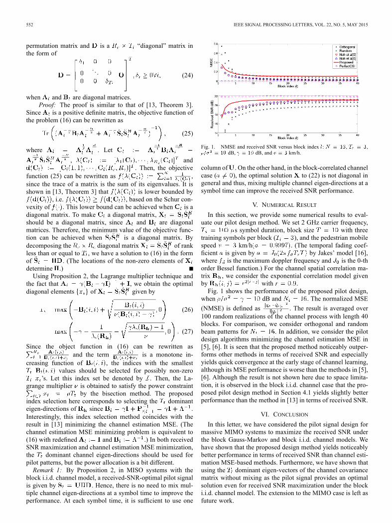
Fig. 1. NMSE and received SNR versus block index : , ,dB, dB, and km/h.
column of . On the other hand, in the block-correlated channelcase ( ), the optimal solution to (22) is not diagonal ingeneral and thus, mixing multiple channel eigen-directions at asymbol time can improve the received SNR performance.
V. NUMERICAL RESULT
In this section, we provide some numerical results to eval-uate our pilot design method. We set 2 GHz carrier frequency,
s symbol duration, block size with threetraining symbols per block ( ), and the pedestrian mobilespeed km/h . (The temporal fading coef-ficient is given by by Jakes’ model [16],where is the maximum doppler frequency and is the 0-thorder Bessel function.) For the channel spatial correlation ma-trix , we consider the exponential correlation model givenby with .Fig. 1 shows the performance of the proposed pilot design,
when dB and . The normalized MSE
(NMSE) is defined as . The result is averaged over100 random realizations of the channel process with length 40blocks. For comparison, we consider orthogonal and randombeam patterns for . In addition, we consider the pilotdesign algorithms minimizing the channel estimation MSE in[5], [6]. It is seen that the proposed method noticeably outper-forms other methods in terms of received SNR and especiallyyields quick convergence at the early stage of channel learning,although its MSE performance is worse than the methods in [5],[6]. Although the result is not shown here due to space limita-tion, it is observed in the block i.i.d. channel case that the pro-posed pilot design method in Section 4.1 yields slightly betterperformance than the method in [13] in terms of received SNR.
VI. CONCLUSION
In this letter, we have considered the pilot signal design formassive MIMO systems to maximize the received SNR underthe block Gauss-Markov and block i.i.d. channel models. Wehave shown that the proposed design method yields noticeablybetter performance in terms of received SNR than channel esti-mation MSE-based methods. Furthermore, we have shown thatusing the dominant eigen-vectors of the channel covariancematrix without mixing as the pilot signal provides an optimalsolution even for received SNR maximization under the blocki.i.d. channel model. The extension to the MIMO case is left asfuture work.
SO et al.: PILOT SIGNAL DESIGN FOR MASSIVE MIMO SYSTEMS 553
REFERENCES[1] F. Rusek, D. Persson, B. K. Lau, E. G. Larsson, O. Edfors, F.
Tufvesson, and T. L. Marzetta, “Scaling up MIMO: Opportunities andchallenges with very large arrays,” IEEE Signal Process. Mag., vol.30, no. 1, pp. 40–60, Jan. 2013.
[2] T. L. Marzetta, “Noncooperative cellular wireless with unlimited num-bers of base station antennas,” IEEE Trans. Wireless Commun., vol. 9,no. 11, pp. 3590–3600, Nov. 2010.
[3] J. Hoydis, S. ten Brink, andM. Debbah, “MassiveMIMO in the UL/DLof cellular networks: How many antennas do we need,” IEEE J. Sel.Areas Commun., vol. 31, no. 2, pp. 160–171, Feb. 2013.
[4] C. Shepard, H. Yu, N. Anand, L. E. Li, T. L. Marzetta, R. Yang, andL. Zhong, “Argos: Practical many-antenna base stations,” in Proc. Mo-biCom, Istanbul, Turkey, Aug. 2012.
[5] S. Noh, M. D. Zoltowski, Y. Sung, and D. J. Love, “Pilot beam patterndesign for channel estimation in massive MIMO systems,” IEEE J. Sel.Topics Signal Process., vol. 8, no. 5, pp. 787–801, Oct. 2014.
[6] S. Noh, M. D. Zoltowski, Y. Sung, and D. J. Love, “Training signaldesign for channel estimation in massive MIMO systems,” in Proc.ICASSP, Florence, Italy, May 2014.
[7] J. Choi, D. J. Love, and P. Bidigare, “Downlink training techniquesfor FDDmassive MIMO systems: Open-Loop and closed-loop trainingwith memory,” IEEE J. Sel. Topics Signal Process., vol. 8, no. 5, pp.802–814, Oct. 2014.
[8] B. Hassibi and B. M. Hochwald, “Howmuch training is needed in mul-tiple-antenna wireless links,” IEEE Trans. Inf. Theory, vol. 49, no. 4,pp. 951–963, Apr. 2003.
[9] D. J. Love, J. Choi, and P. Bidigare, “A closed-loop training approachfor massive MIMO beamforming systems,” in Proc. IEEE CISS, Bal-timore, MD, USA, Mar. 2013.
[10] S. Noh, M. D. Zoltowski, Y. Sung, and D. J. Love, “Optimal pilotbeam pattern design for massive MIMO systems,” in Proc. IEEEASILOMAR, Pacific Grove, CA, USA, Nov. 2013.
[11] S. Stein, “Fading channel issues in system engineering,” IEEE J. Sel.Areas Commun., vol. 5, no. 1, pp. 68–89, Feb. 1987.
[12] A. F. Molish, Wireless Communications. Hoboken, NJ, USA: Wiley,2010.
[13] J. H. Kotecha and A. M. Sayeed, “Transmit signal design for op-timal estimation of correlated MIMO channels,” IEEE Trans. SignalProcess., vol. 52, no. 2, pp. 546–557, Feb. 2004.
[14] T. Kailath, A. H. Sayed, and B. Hassibi, Linear Estimation. UpperSaddle River, NJ, USA: Prentice-Hall, 2000.
[15] Z. Luo,W.Ma, A.M. So, Y. Ye, and S. Zhang, “Semidefinite relaxationof quadratic optimization problems,” IEEE Signal Process. Mag., vol.27, no. 3, pp. 20–34, May 2010.
[16] W. C. Jakes, Microwave Mobile Communication. New York, NY,USA: Wiley, 1974.