Embed Size (px)
Citation preview

IEEE JOURNAL OF SOLID-STATE CIRCUITS, VOL. 40, NO. 11, NOVEMBER 2005 2305
A 1.25-inch 60-Frames/s 8.3-M-PixelDigital-Output CMOS Image Sensor
Isao Takayanagi, Member, IEEE, Miho Shirakawa, Koji Mitani, Masayuki Sugawara, Member, IEEE, Steinar Iversen,Jørgen Moholt, Junichi Nakamura, Senior Member, IEEE, and Eric R. Fossum, Fellow, IEEE
Abstract—The ultrahigh-definition television (UDTV) camerasystem requires an image sensor having four times higher resolu-tion and two times higher frame rate than the conventional HDTVsystems. Also, an image sensor with a small optical format andlow power consumption is required for practical UDTV camerasystems. To respond to these requirements, we have developed an8.3-M-pixel digital-output CMOS active pixel sensor (APS) forthe UDTV application. It features an optical format of 1.25 inch,low power consumption of less than 600 mW at dark, while repro-ducing a low-noise, 60-frames/s progressive scan image. The imagesensor is equipped with 1920 on-chip 10-bit analog-to-digitalconverters and outputs digital data stream through 16 paralleloutput ports. Design considerations to reproduce a low-noise,high-resolution image at high frame rate of 60 fps are described.Implementation and experimental results of the 8.3-M-pixelCMOS APS are presented.
Index Terms—Active pixel sensor, CMOS image sensor, HDTV,parallel architecture.
I. INTRODUCTION
WITH SATELLITE digital broadcasting using a 2-mil-lion-pixel High-Definition Television (HDTV) format,
and digital cinemas being reduced to practical use, a 4 k 2k format is considered as the next-generation format [1], [2].Technology developments toward the ultrahigh-definitionimage capture have thus been actively performed [3]–[6].Examples of ultrahigh-resolution image sensors, of which res-olution exceeds the HDTV standard, include a 2.5-inch opticalformat CCD image sensor with 4080 (H) 2040 (V) pixels[3], [6] and a 35-mm optics compatible CMOS image sensorwith 3840 (H) 2160 (V) pixels [4], operating in a progressivescanning mode at 60 frames/s and at 30 fps, respectively. Due tothe large format sizes of these sensors, it was difficult to realizecompact camera systems. Also, a CCD-based camera headconsumes power of greater than 10 W per channel. Loweringthe sensor power consumption would offer a significant benefit.It simplifies camera-head design and prevents the heat genera-tion inside a camera head, and thus can avoid an unnecessaryincrease of temperature.
Manuscript received August 11, 2004; revised June 15, 2005.I. Takayanagi and J. Nakamura are with the Japan Imaging Design Center, Mi-
cron Japan Ltd., Tokyo 144–8721, Japan (e-mail: [email protected]).M. Shirakawa, K. Mitani, and M. Sugawara are with the NHK Science and
Technical Laboratories, Setagaya-ku, Tokyo 175-8510, Japan.S. Iversen and J. Moholt are with Micron Europe Ltd., Norway, Oslo
NO-0349, Norway.E. R. Fossum is with the Department of Electrical Engineering, University of
Southern California, Los Angeles, CA 90089 USA.Digital Object Identifier 10.1109/JSSC.2005.857375
Fig. 1. Distribution of image sensor formats for video applications. Note thatour sensor is positioned at 60 fps and 8 M-pixels.
A data rate exceeding 500 MHz, that is 8 times higher thanthat of the HDTV, is required to achieve a 60-fps operationwith a pixel count of over 8 million pixels. The image sen-sors cited above have parallel analog output ports to realize thiseffective data rate. For example, the CCD sensor [3] has 16parallel output ports, each operating at 37.125 MHz. However,this analog approach complicates analog processing circuits ina camera head. A full digital output scheme could alleviate thisdifficulty. Therefore, a smaller format sensor with lower powerconsumption and full digital interface is highly demanded.
In order to respond to this demand, we have developed a 1.25-inch, 8.3-M-pixel digital-output CMOS image sensor, whichcan operate at 60 fps in a progressive scanning mode. The sensorspecification matches the standard Real-time HRI-01 [1] thatwas proposed by ITU (International Telecommunication Unit)for next-generation extremely high-resolution motion picturesin 1995.
Fig. 1 shows how each imaging application is mapped as afunction of the frame rate and the number of pixels. The devel-oped sensor covers most of the imaging applications, includingUltraHigh Definition TV (UDTV) and digital cinema applica-tions.
In this paper, design considerations to realize a large-formathigh-resolution high-frame-rate digital-output CMOS imagesensor are described in Section II. Implementation of the imagesensor is presented in Section III, followed by descriptions ofcharacterization results in Section IV.
II. DESIGN CONSIDERATIONS
A. Choice of Optical Format
Previous sensors had relatively large pixel sizes (8.4 m [3],[6], 7.5 m [4]), which required a large lens, thus making itdifficult to realize a compact and lightweight camera system.
0018-9200/$20.00 © 2005 IEEE

2306 IEEE JOURNAL OF SOLID-STATE CIRCUITS, VOL. 40, NO. 11, NOVEMBER 2005
Also, the large die sizes require a stitching technique to fabricatethe devices, where multiple photolithography processes usingseveral reticle sets are needed.
We selected a 1.25-inch optical format so that the die size ofthe chip fits into the standard reticle window of 20 mm 20 mm,while attempting to design a pixel as large as possible from anoptical performance point of view. In order to fit the imagingarray having 8.3 M (3840(H) 2160 (V)) pixels to the 1.25-inchformat, a pixel size of 4.2 m was chosen [7], [8].
B. Digital Output Versus Analog Output
It is obvious that a full digital interface eliminates complexityassociated with designing analog front-end circuits. In partic-ular, the benefit gains more in case the sensor having a multipleoutput ports to obtain sufficient effective data rate. In addition,the digital output scheme could have an advantage in power con-sumption over the analog output counterpart as described below.Assuming the digital output buffer has sufficient driving capa-bility, the power consumed by digital output pads isgiven by
(1)
where is the number of ADC bits, is the transition prob-ability for the th bit for a given illumination level, is theload capacitance, is the digital power supply voltage, and
is the effective data rate. On the other hand, the power con-sumed by an analog output buffer is represented by
(2)
where is the analog power supply voltage, is a currentflowing through , and is the time period, most likely aframe time, respectively. If we consider an average value of theoutput current over the frame time, (2) is rewritten as
(3)
where the average current is a function of , which is therequired frequency bandwidth for the output buffer. Assuminga single-pole buffer, the frequency bandwidth is given by
(4)
With a formula of the transconductance of a MOS transistorof
(5)
where denotes the mobility, the gate capacitance per unitarea, the width and the length of a primary transistor in thebuffer. From (4) and (5), one can obtain
(6)
It is seen in (6) that the required current is proportional to thesquare of the frequency bandwidth. Comparing (1) and (2) with
Fig. 2. Power consumption of output buffers as a function of data rate.Parameters: V = 3:3 V, C = 15 pF, � � C = 60 �A/V ;m = 4; � =0:25;N = 10. For analog buffers, (W=L) = 400; 600; 800; 1000;1200.
other equations, it is concluded that the digital output schemeconsumes less than the analog output scheme in the case of
(7)
where , is an effective transition probability[see (1)], and is a factor that relates the frequency bandwidth
and the data rate . An example illus-trating the relationship (7) is shown in Fig. 2, where the iden-tical capacitive loads for both cases are assumed. Fromthe figure, it is shown that power consumption of the digital ap-proach is lower than that of the analog counterpart when the datarate greater than a few tens of MHz is required.
C. Rationale of Column Parallel On-Chip Analog-to-DigitalConversion
In this subsection, power consumption and noise of two ar-chitectures of CMOS image sensors with on-chip analog-to-dig-ital converters (ADCs) are analyzed: one is with only one ADC(called the “serial ADC” type) and the other with column par-allel ADCs, where an ADC is placed in each column and whereall ADCs operate in parallel. The serial ADC operates at a pixeloutput rate, while each ADC in the column parallel architectureoperates at the row rate. Let us take an image sensor, having
pixels and operating at frames/s.1) Power Consumption: Conversion rates for the serial and
column-parallel approaches are approximately given by
Hz (8)
Hz (9)
where , and 1 H denote the conversionrates of the serial and column-parallel architectures and the rowtime, respectively. Assuming a CMOS operational transcon-ductance amplifier (OTA) is used in an ADC, the impact of theconversion rates on the power consumption is analyzed. Thegain bandwidth (GBW) of the CMOS OTA is given by
(10)

TAKAYANAGI et al.: A 1.25-INCH, 60-FRAMES/S, 8.3-M-PIXEL DIGITAL-OUTPUT CMOS IMAGE SENSOR 2307
Fig. 3. Imaging array architecture of a CMOS image sensor.
where and are the transconductance given by (5), and theeffective load capacitance, respectively. Now, as the bias current
increases to obtain the required GBW that is determinedfrom the conversion rate , so must , in orderto keep the same effective gate-source voltage . Therefore,(10) is rewritten as
(11)
and thus goes up linearly with GBW, which yields iden-tical power consumption for both architectures from (8) and (9),since GBW is proportional to and there are ADCsoperating in parallel in the column-parallel architecture.
However, when we consider the parasitic capacitance at theinput node of an OTA, the bias requirements in the serial ADCarchitecture become much greater, since the feedback factor ofthe amplifier degrades due to a larger input transistor and muchlarger parasitic capacitance connecting to the input node of theOTA. In addition, increasing further in the serial ADC ap-proach may be limited at a certain practical point, which in turnmakes proportional to . In this case, goes up with
and thus the column-parallel approach is expected toprovide lower power consumption.
2) Noise: In the switched capacitor circuit, the samplingprocess folds the noise from the high-frequency region to thefrequency region below the sampling frequency. Amplifierthermal noise is proportional to and the noiseafter sampling is given by
(12)
The noise associated with a sample-and-hold operationhas the same relationship as (12). Thus, noise level is indepen-dent of the sampling rate and the noise levels in both architec-tures are expected to be the same. However, it is very difficult toapply noise cancellation techniques to high-speed signal chainsthat would be used in the serial ADC architecture.
3) Conclusion: Although, in reality, different types of ADCshould be considered to match the requirements and/or con-straints of each architecture, it can be concluded from the dis-cussions above that the column parallel architecture is expectedto provide/yield both lower power consumption and lower noiselevels than those of the serial ADC architecture, when the sameADC topology is used for both architectures.
D. Large Array Effect
If a large-format array is built based on the architecture shownin Fig. 3, a problem would occur due to the drop along thepower and ground lines. When a row is selected for readout,the pixel bias currents flow from to . During thisreadout period, voltages along the line cannot remain at theground level due to parasitic resistance.
The bias current is given by
(13)
where is the gate-source voltage for the th load transistor,MLD, is the voltage at the column , and isthe threshold voltage. Thus, as the rise due to the par-asitic resistance on the ground line, the bias current decreases.The output voltage change due to the raised is approxi-mately given by
(14)
where is the voltage change on the line. This outputvoltage change could be suppressed by the correlated doublesampling (CDS). The main concern is that the decreased biascurrents due to the reduced effective of may resultin variations in time constant for charging and discharging a

2308 IEEE JOURNAL OF SOLID-STATE CIRCUITS, VOL. 40, NO. 11, NOVEMBER 2005
Fig. 4. Internal bock diagram of 8-M-pixel UDTV image sensor having a shared ADC architecture. Pixel pitch is 4.2 �m. Layout pitches ofamplifier/sample-and-hold and ADC are 8.2 �m and 16.8 �m, respectively.
sample-and-hold capacitor . The time constant of chargingthe sample-and-hold capacitor is approximately given by
(15)
where is a parasitic capacitance on a column line. Thus,a resulting voltage on the hold capacitor may change when thepulsewidth of the sample-and-hold pulse is comparable to thetime constant. This may happen since a higher resolution imagesensor requires narrower pulse widths to obtain a given framerate.
Another concern is the source follower gain variation due tothe variation in bias currents.
The same mechanism of the voltage change applies to theline. However, it affects the output voltage little since the
driver transistor operates in its saturation region and thusthe drain voltage has minimal affect on the drain current. Thecontribution from a change of to the pixel follower outputis approximated as
(16)
where is the drain-source resistance of . A value ofis several tens to hundreds in a pixel source fol-
lower circuit, thus an output change due to thedegradation can be neglected.
On the other hand, a possible problem with the voltage changeon the line is associated with the photodiode reset op-eration. In case of the “hard reset” where the reset transistor
operates in its linear region, a local voltage is sam-pled on the photodiode capacitance. Thus, the initial photodiodevoltages on a row will/may not be identical. In addition, if the
line is contaminated by noise, that noise is sampled ona photodiode.
Fig. 5. Chip layout.
These issues associated with the power drop and the groundbounce need to be addressed in designing high-performancelarge-format CMOS image sensors.
E. I/O Pins and Package
Large spike currents could flow when column parallel circuitshave a simultaneous transition from one state to the other, whichintroduces fluctuations on bias/reference voltages. Among thebias/reference voltages, of biggest concern is the primary ref-erence voltage to the column parallel ADCs and analog .In order to stabilize the possible fluctuations on bias/referencevoltages, it is preferable that each of several important bias/ref-erence voltages has a multiple number of pads. In addition,placing several decoupling capacitors as close as possible to thebonding pads for the above-mentioned bias/reference voltagescould help.

TAKAYANAGI et al.: A 1.25-INCH, 60-FRAMES/S, 8.3-M-PIXEL DIGITAL-OUTPUT CMOS IMAGE SENSOR 2309
Fig. 6. Operation sequence for row cycles.
III. IMPLEMENTATION
A. Overall Architecture
A UDTV system [7], [8] requires 8.3 million pixels, 60 fpsoperation in the progressive scanning mode, which translatesto approximately 500 MHz pixel readout rate. In order to elim-inate the difficulty of handling analog signals with such a widefrequency bandwidth, ADCs are implemented on-chip. Theon-chip analog-to-digital (A/D) conversion scheme also offersa possibility of lower power consumption than an analog-outputscheme as described in Section II-B. A block diagram of theUDTV sensor and a layout plot are shown in Figs. 4 and 5,respectively. A sensor architecture with column-parallel suc-cessive-approximation 10-bit ADCs, column-parallel 2 SRAMbanks [9], and 16 parallel output ports was adopted to achievethe high throughput of over 5 Gb/s. The total number of pixelsis 3936 2196, with the effective number of pixels being3840 2160. Although the sensor reported in [9] achieved9.75 Gb/s, with a 7.0 m pixel and master clock frequencyof 66 MHz, which exceeds the data throughput of 5.2 Gb/sfor this UDTV application, the smaller pixel size of 4.2 mand the larger number of pixels required us to implementseveral improvements and customization. These include anewly designed smaller pixel, a sufficient number of opticalblack pixels to obtain precise black level clamp, implemen-tation of a column-gain stage, a shared-ADC scheme withsample-and-hold circuits, operational timing modification forlow-noise performance, noise-robust bias circuits, and carefulbus routing for high-quality image reproduction. One 10-bitADC is shared by two columns and the column parallel signalprocessors are split into two banks, each having 984 ADCs atthe top and bottom of the array. This architecture allows theimaging array to be located at the center of the chip.
Fig. 6 shows a row timing diagram. The one row time is ap-proximately 7.5 s. Following the column-analog gain stage,which is activated at the beginning of a row time, a signal voltageand an offset voltage after the pixel reset are sampled and held(“Gain & SH”). These two samples are used to suppress pixel-wise FPN. The gaining and the sample-and-hold operations areperformed in parallel for all columns. No data readout is per-formed during this period to avoid potential digital noise inter-ference, since this analog processing period is critical to obtainlow-noise performance.
Two A/D conversion cycles (“ADC1” and “ADC2”) follow inthe remaining period since one ADC is shared by two columnsas shown in Fig. 4. The digital data is sequentially sampled intothe front-end memory SRAM 1 as soon as it is available fromthe ADC during digitization, and is shifted into the back-endmemory SRAM 2 for readout when the digitization is com-plete. The back-end memory SRAM 2 is read out differentiallyusing on-chip sense-amplifiers to output a digital data stream.This configuration permits the readout of the previous row dataduring the “ADC” periods. The timing control circuits generateall the required pulses from four input pulses, namely, a masterclock, a frame trigger, a row trigger, and a shutter trigger. Sev-eral test modes were also implemented.
B. Pixel
The 4.2- m pixel consists of a deep n-well/p-substrate pho-todiode with on-chip microlens and three transistors, namely adriver transistor , a reset transistor , and a row selecttransistor , as shown in Fig. 3. The fill factor of the photo-diode without the microlens is about 40%. In order to obtainhigh-precision optical black level clamp, optical black pixelswith a light shield, consisting of a metal layer and black filtermaterial, are implemented at the periphery of the effective pixelarray.
C. Pixel Bias Circuits With Immunity From Power/GroundNoise
In order to avoid the possible shading and noise mixturefrom power supplies, we have implemented a bias stabilizationscheme for the pixel bias voltage and for the bias current of apixel source follower amplifier, as illustrated in Fig. 7.
As mentioned in Section II, when fluctuates tempo-rary, a photodiode latches the deviation as a temporal noise. Itis well known that the noise associated with pixel power supplycan be suppressed by using a photodiode soft reset [10], wherethe reset transistor operates in its subthreshold region.However, the soft reset has a drawback of image lag that causesa significant problem in high-end video systems. A fill-and-spilloperation, where the hard reset and the soft reset are performedsequentially, improves the image-lag but it needs an additionaloperation for the pixel readout period and makes it difficult toachieve the 60 frames/s over 2000 rows. Accordingly, we chose

2310 IEEE JOURNAL OF SOLID-STATE CIRCUITS, VOL. 40, NO. 11, NOVEMBER 2005
Fig. 7. Block diagram of bias stabilization scheme.
the hard reset operation to realize low image lag and fast pixeloperation. It requires a clean pixel power supply voltage and weachieved this with the bias configuration, as shown in Fig. 7.
A voltage regulator is implemented in each column that sup-plies pixel power voltage that is referenced to a ref-erence voltage . The is kept quiet withoutany use for power supply (no current draw), and thus the voltageregulators can supply a stable and uniform pixel power voltageto each pixel. In order to perform the photodiode hard reset,
supplied from the regulator is set to approximately200 mV lower than so that operatesin its linear mode.
A Similar method is also used in a pixel bias current gener-ator configuration. A current generator is implemented in eachcolumn. The current generator supplies a bias current refer-encing to a reference ground REFGND that is isolated from thenoisy power GND bus. The pixel bias current is set at 15 Ato drive a large parasitic capacitance on the vertical signal line.Multiplied by the number of column parallel circuits of 1968in each top and bottom readout block, the total pixel bias cur-rent consumed in each block is then 29.5 mA during the pixelreadout. The bias current flows through the ground bus line thatis more than 16.5 mm (4.2 m 3936) long. When the groundline is grounded at both ends of the array, a voltage increase atthe center of the ground bus line is given by
(17)
where and are the wire length and width of theground bus line, respectively, is the metal sheet resis-tance, and is the total bias current. With mm,
m, mA, and sq.,the peak voltage increase is estimated to be about 60 mV. If thebias current generator refers to the power ground voltage and thecommon bias voltage , the resulting bias current decreasesby 3–6 A, assuming for the bias transistor of 50–100 A/V.
On the other hand, much more uniform bias currents can beobtained by referring to the reference ground (REFGND) asshown in Fig. 7, which means that the proposed schemeis immune from the ground bounce. In addition to thecommon/power noise rejection and the immunity from spatialvoltage deviation, another benefit from the scheme is isolationbetween columns. Since individual voltage/bias generators areimplemented in each column, an identical pixel operation isguaranteed, which avoids a possible noise coupling betweencolumns through common/power nodes.
D. Column Amplifier
Prior to the ADCs, an analog gain stage, which uses acapacitive feedback inverter amplifier with five gain settings
, is employed. The gain isdefined as a total analog gain from the photodiode to the ADCinputs. At the lowest gain of 0.7, an ADC input window of750 mV covers a full linear output range of the pixel source fol-lower. The individual regulation scheme described in the pixelbias circuit above is also introduced in the column amplifiercircuit. Fixed-pattern noise (FPN) generated in each pixel andthe column analog signal chain is suppressed before the A/Dconversion.
E. Analog-to-Digital Converter
The column parallel ADC is based on a charge redistributionsuccessive approximation (SA) ADC [11], which requires only
conversion steps for -bit resolution, thus suitable for high-speed operation. A binary-scaled capacitor bank is equipped forsignal (consisting of light dependent signal and an offset) and acapacitor which value is close to the sum of the binary-scaledcapacitors is equipped for the offset signal. A comparator com-pares these two values in the successive approximation proce-dures and generates digital codes. A comparator offset voltagecan be suppressed by using a calibration capacitor digital-to-analog converter. The automatic calibration routine is run for

TAKAYANAGI et al.: A 1.25-INCH, 60-FRAMES/S, 8.3-M-PIXEL DIGITAL-OUTPUT CMOS IMAGE SENSOR 2311
Fig. 8. Full output image.
every frame to compensate for temperature drifting. Calibrationvalues can also be manually written to and read from the ADCsthrough a dedicated serial interface. Details of the column par-allel SA ADC are reported in [9].
In a column parallel A/D conversion, large spike currentscould flow at a simultaneous transition of significant bits, forwhich larger binary-scaled capacitor is switched on or off.Therefore, on-chip decoupling capacitors are implemented forprimary reference voltages for the ADCs. Off-chip decouplingcapacitors are also used as described in Section II-E.
F. Digital Control
Three digital control signals control the sensor operation,namely, Frame trigger, Row trigger, and Shutter trigger. Thesesignals are fed to an on-chip timing generator, each triggering aframe sequence, a row sequence and electronic rolling shuttertiming. The default operation is a 60-fps progressive scan.However, a 30-fps progressive scanning mode is also possibleby adjusting the input timing of Frame trigger and Row trigger.
IV. PERFORMANCE
A. Sensitivity
At the column analog gain setting of 1.0 and the ADCinput window of 750 mV, sensitivity with on-chip microlens ismeasured to be 4.2 k bits/lux-s (3.0 V/lux s) using a 2700 Klight source and an IR-cut filter of which cut-off wavelengthis 650 nm. Conversion gain of 0.06 LSB/e is extracted fromthe photon shot noise measurement, which corresponds to43 V/e at the pixel electrode. Random noise and dynamic
TABLE ISUMMARY OF NOISE (gain = 1:0; 60 fps)
TABLE IIPOWER CONSUMPTION (V = 3:3 V, 60 fps)
range are measured to be 2.5 and 52 dB, respectively.The random noise is equivalent to noise electrons of 42 e .
When analog gain is set at 0.7, random noise is measured tobe 1.8 and dynamic range increases to 55 dB, whichsuggests the noise is determined by the pixel noise. The numberof saturation signal charge is 25 000 e .
B. Noise
Both random noise (RN) and fixed pattern noise (FPN) aremeasured under dark conditions with the following procedure.First, the random noise component is removed by averaging
2312 IEEE JOURNAL OF SOLID-STATE CIRCUITS, VOL. 40, NO. 11, NOVEMBER 2005
TABLE IIISPECIFICATION AND PERFORMANCE OF THE 8.3-M-pixel CMOS APS
output data over 32 frames. With this data set, row-random FPNand column-random FPN are calculated by averaging 100 dataover the vertical direction and over the horizontal direction,respectively. The pixel random FPN is then extracted by sub-tracting the row- and column-random FPN from the total FPNvalue. Due to the readout architecture shown in Fig. 4, two- andfour-column cycle FPN were expected to appear. As summa-rized in Table I, the column random FPN is a dominant FPNcomponent but a 4-column cycle FPN is not found to be sig-nificant. Also seen from Table I is that the pixel random FPN issufficiently suppressed by on-chip FPN suppression circuit. Thetotal FPN is less than the random noise level [13].
Temporal random noise is measured by subtracting the abovementioned FPN data from the original video signal. Since thereset-noise component is estimated to be 35 e , the resultssuggest the random noise is dominated by the reset noise. It isconfirmed that the effect of the bias stabilization circuits workwell as no shading is detected.
C. Power Consumption
Power consumption [13] was measured to be less than600 mW at dark, including the power consumed by outputdrivers when the sensor operates at 60 fps in a progressivescanning mode with master clock frequency of 49.5 MHz and3.3-V supply. Table II summarizes the power consumption ofeach circuit block. The power consumed by the interface blockincludes those of input buffers for clocks, a timing generator,in addition to that of output buffers. When the sensor is atdark, it is 66 mW. When the sensor is illuminated, power
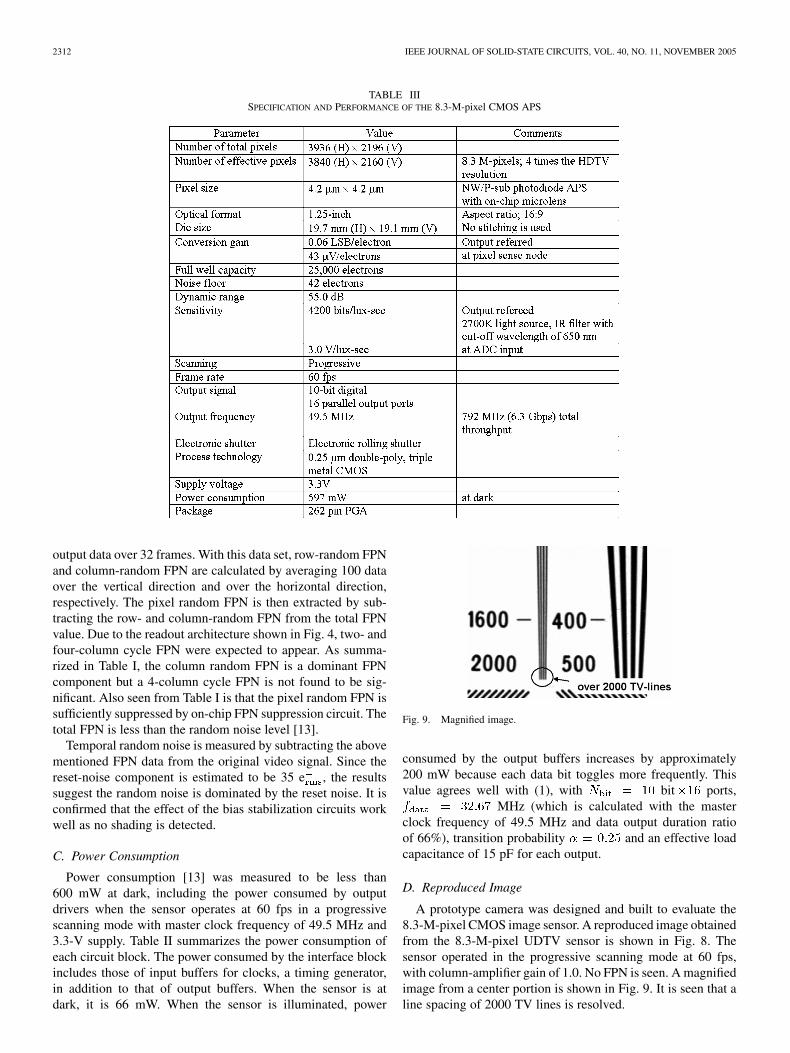
Fig. 9. Magnified image.
consumed by the output buffers increases by approximately200 mW because each data bit toggles more frequently. Thisvalue agrees well with (1), with bit ports,
MHz (which is calculated with the masterclock frequency of 49.5 MHz and data output duration ratioof 66%), transition probability and an effective loadcapacitance of 15 pF for each output.
D. Reproduced Image
A prototype camera was designed and built to evaluate the8.3-M-pixel CMOS image sensor. A reproduced image obtainedfrom the 8.3-M-pixel UDTV sensor is shown in Fig. 8. Thesensor operated in the progressive scanning mode at 60 fps,with column-amplifier gain of 1.0. No FPN is seen. A magnifiedimage from a center portion is shown in Fig. 9. It is seen that aline spacing of 2000 TV lines is resolved.

TAKAYANAGI et al.: A 1.25-INCH, 60-FRAMES/S, 8.3-M-PIXEL DIGITAL-OUTPUT CMOS IMAGE SENSOR 2313
Fig. 10. Photograph of the image sensor in a 262-pin ceramic PGA package.
A photograph of the image sensor sample in a 262-pin ce-ramic PGA package is shown in Fig. 10. A custom packagewas designed and built, where several decoupling capacitors canbe coupled to the critical bias/reference voltages mentioned inSection II-D at one end of a bonding wire on a bottom plate ofthe package cavity. This particular sensor sample is without theglass lid and the black filter for demonstration purposes.
Specifications and performance are summarized in Table III.
V. CONCLUSION
We have developed an 8.3-M-pixel digital-output CMOSAPS for UDTV application. It features a small optical formatof 1.25-inch, low power consumption of less than 600 mW atdark, while reproducing a low-noise, 60-frames/s progressivescan image. The digital output scheme with a column parallelon-chip ADC architecture permits much lower power con-sumption than the analog output scheme used in CCD imagesensors. This advantage is enhanced as data rate increases. Inaddition, image quality will be improved in the near future byusing a pinned photodiode, which features low read noise andlow dark current. This image sensor will pave the way to futuredigital cinema systems and tele-medicine applications as wellas UDTV systems.
ACKNOWLEDGMENT
The authors acknowledge F. Okano, A. Krymski, N. E. Bock,J. Solhusvik, P. O. Pahr, G. Strand, T. Bales, and Y. Mo for theirvaluable discussions.
REFERENCES
[1] Extremely High Resolution Imagery, Rec. ITU-R BT. 1201, 1995.[2] Digital Cinema System Specification, Digital Cinema Initiatives, LLC,
2005.[3] C. Smith, M. Farrier, K. Mitani, Q. Tang, and G. Ingram, “An 8 M-CCD
for an ultra high definition TV camera,” in Program IEEE Workshopon Charge-Coupled Devices and Advanced Image Sensors, Japan, Jun.1999, pp. 175–178.
[4] S. Stough and W. Hill, “High-performance electro-optic camera proto-type,” SMPTE J., pp. 140–146, Mar. 2001.
[5] K. Mitani, M. Sugawara, and F. Okano, “Experimental ultrahigh-defi-nition color camera system with three 8M-pixel CCDs,” SMPTE J., pp.148–153, Apr. 2002.
[6] A. Theuwissen, J. Coghill, L. Ion, F. Shu, H. Siefken, and C. Smith,“Ultra-high resolution image capturing and processing for digital cine-matography,” IEEE ISSCC Dig. Tech. Papers, pp. 162–163, Feb. 2003.
[7] I. Takayanagi, M. Shirakawa, K. Mitani, M. Sugawara, S. Iversen, J.Moholt, J. Nakamura, and E. R. Fossum, “A 1�1/4 inch 8.3 M pixeldigital output CMOS APS for UDTV application,” IEEE ISSCC Dig.Tech. Papers, pp. 216–217, Feb. 2003.
[8] S. Iversen, J. Moholt, J. Solhusvik, I. Takayanagi, J. Nakamura,E. R. Fossum, M. Shirakawa, K. Mitani, and M. Sugawara, “An8.3-megapixel, 10-bit, 60 fps CMOS APS,” presented at the IEEEWorkshop on Charge-Coupled Devices and Advanced Image Sensors,Elmau, Germany, May 2003.
[9] A. I. Krymski, N. E. Bock, N. Tu, D. V. Blerkom, and E. R. Fossum, “Ahigh-speed, 240-frames/s, 4.1-megapixel CMOS sensor,” IEEE Trans.Electron Devices, vol. 50, no. 1, pp. 130–135, Jan. 2003.
[10] B. Pain, G. Yang, M. Ortiz, C. Wrigley, B. Hancock, and T. Cun-ningham, “Analysis and enhancement of low-light-level performanceof photodiode-type CMOS active pixel imagers operated with sub-threshold reset,” in Program IEEE Workshop on Charge-CoupledDevices and Advanced Image Sensors, Jun. 1999, pp. 140–143.
[11] Z. Zhou, B. Pain, and E. R. Fossum, “CMOS active pixel sensor withon-chip successive approximation analog-to-digital converter,” IEEETrans. Electron Devices, vol. 44, no. 10, pp. 1759–1763, Oct. 1997.
[12] M. Shirakawa, T. Yamashita, K. Mitani, M. Sugawara, I. Takayanagi, J.Nakamura, S. Iversen, J. Moholt, and E. R. Fossum, “Design consider-ation of FPN suppression circuit for a 1.25 8.3 M-pixel digital outputCMOS APS,” presented at the IEEE Workshop on Charge-Coupled De-vices and Advanced Image Sensors, Elmau, Germany, May 2003.
[13] I. Takayanagi and J. Nakamura, “Ultra-high definition video CMOSimage sensor,” ITE Tech. Report, vol. 27, no. 67, pp. 1–4, Nov. 2003.In Japanese.
Isao Takayanagi (M’02) received the M.S. degree inphysics from Gakushuin University, Tokyo, Japan, in1987.
He joined Olympus Optical Co., Ltd. in 1987 andwas engaged in research and development of activepixel imagers including static induction transistor(SIT) imagers, charge modulation device (CMD)imagers and amplified MOS imagers (AMI). Heworked on pixel device physics and modeling,imager technology development, on-chip imageprocessing and scientific imagers. In 2000, he joined
Photobit Corporation and was engaged in contract R&D where he performedcustom CMOS imager designs. Since 2001, he has been with the Japan ImagingDesign Center, Micron Japan Ltd., Tokyo.
Mr. Takayanagi is a member of the Institute of Image Information and Tele-vision Engineers in Japan and the Japan Society of Applied Physics.
Miho Shirakawa received the Masters degree inengineering from the Tokyo Institute of Technology,Tokyo, Japan, in 1993.
From 1993 to 2003, she worked for NHK Scienceand Technical Laboratories. From 1993 to 1997, shedeveloped high breakdown voltage CMOS sensorsto build up high-gain avalanche rushing amorphousphotoconductors. From 2001 to 2003, she wasengaged in developing UDTV camera systems,especially in design of noise reduction circuits for an8.3-M-pixel CMOS APS. Since 2003, she has been
with NHK Broadcast Engineering Department, Tokyo.
2314 IEEE JOURNAL OF SOLID-STATE CIRCUITS, VOL. 40, NO. 11, NOVEMBER 2005
Kohji Mitani received B.S. and M.S. degrees inelectronic engineering in 1985 and 1987, respec-tively, and the Ph.D. degree in 1999, from KyotoUniversity, Kyoto, Japan.
In 1987, he joined the Science and TechnicalResearch Laboratories, NHK, Tokyo. Since then,he has been working on solid-state image sensorcameras. His research interests include very highdata rate image pickup methods, particularly a veryhigh resolution and very high frame rate imageacquisition system.
Dr. Mitani is a member of the Institute of Image Information and TelevisionEngineers of Japan.
Masayuki Sugawara (M’03) received the B.S. andM.S. degrees in electric communication engineeringand the Ph.D. degree in electronic engineering fromTohoku University, Sendai, Japan, in 1981, 1983, and2003, respectively.
He joined NHK (Japan Broadcasting Corpora-tion), Tokyo, Japan, in 1983. Since 1987, he has beenresearching solid-state image sensor and HDTVcamera at the Science and Technical ResearchLaboratories, NHK. At present, he is engaged in theresearch of ultrahigh-definition TV systems.
Steinar Iversen received the M.S.E.E. degreein electronics engineering from the NorwegianUniversity of Science and Technology (NTNU),Trondheim, Norway, in 1998.
He worked for the Norwegian Defense ResearchEstablishment (FFI) from November 1998 and joinedthe Oslo, Norway, office of Photobit Corporation,Pasadena, CA, in August 1999, where he worked onseveral custom CMOS image sensor design projects.Since November 2001, he has been with NorwayImaging Design Center, Micron Europe Ltd., Oslo,
working with digital design as well as leading one custom CMOS image sensordevelopment.
Jørgen Moholt received the B.S.E.E. degree inelectronics engineering from Vestfold UniversityCollege, Horten, Norway, in 1995 and the M.S.E.E.in electronics engineering from the NorwegianUniversity of Science and Technology (NTNU),Trondheim, Norway, in 1998.
He worked for Nordic VLSI ASA, Oslo, Norway,from January 1999 and joined the Oslo, Norway,office of Photobit Corporation, Pasadena, CA,in November 1999, where he worked on severalcustom CMOS image sensor design projects. Since
November 2001, he has been with Norway Imaging Design Center, MicronEurope Ltd., Oslo, working in several areas of analog CMOS design.
Junichi Nakamura (M’92–SM’01) received theB.S. and M.S. degrees in electronics engineeringfrom the Tokyo Institute of Technology, Tokyo,Japan, in 1979 and 1981, respectively, and the Ph.D.in electronics engineering from the University ofTokyo, Tokyo, Japan, in 2000.
He joined Olympus Optical Company, Tokyo, in1981. After working on optical image processing, hewas involved in developments of active pixel sensors,including static induction transistor (SIT) image sen-sors and MOS type image sensors. From September
1993 to October 1996, he was resident at the NASA Jet Propulsion Laboratory,California Institute of Technology, Pasadena, as Distinguished Visiting Scien-tist. In 2000, he joined Photobit Corporation, Pasadena, CA, where he led sev-eral custom sensor developments. Since November 2001, he has been with JapanImaging Design Center, Micron Japan, Ltd., Tokyo.
Dr. Nakamura served as Technical Program Chairman for the 1995, 1999, and2005 IEEE Workshop on Charge-Coupled Devices and Advanced Image Sen-sors and as a member of Subcommittee on Detectors, Sensors and Displays forthe IEDM 2002 and 2003. He is a member of the Institute of Image Informationand Television Engineers of Japan.
Eric R. Fossum (S’80–M’84-SM’91–F’98) receivedthe B.S. degree in physics and engineering fromTrinity College, Hartford, CT, in 1979 and thePh.D. degree in electrical engineering from YaleUniversity, New Haven, CT, in 1984.
As a member of the Electrical Engineering fac-ulty at Columbia University, New York, from 1984 to1990, he and his students performed research on CCDfocal-plane image processing and high speed III–VCCDs. In 1990, he joined the NASA Jet PropulsionLaboratory (JPL), California Institute of Technology,
Pasadena, and managed JPL’s image sensor and focal-plane technology researchand advanced development. He led the invention and development of CMOS ac-tive pixel sensor (APS) camera-on-a-chip and subsequent transfer of the tech-nology to US industry. In 1996, he joined Photobit Corporation as Chief Scien-tist, a company he helped found in 1995, and became CEO of Photobit Tech-nology Corporation in 2000. While at Photobit, he and his staff commercializedthe technology that is now used in camera-phones, web cameras, high-speedcameras, automobiles, biomedical equipment, and digital still cameras. In late2001, Photobit was acquired by Micron Technology Inc., and Dr. Fossum wasnamed a Senior Micron Fellow. He left Micron in 2003 and is currently Ad-junct Professor of Electrical Engineering–Electrophysics at the University ofSouthern California (USC), Los Angeles, and teaches undergraduate physicalelectronics and quantum mechanics. He has also served as Adjunct Professorof Electrical Engineering at the University of California, Los Angeles. He hasserved as primary thesis adviser to 13 graduated Ph.D.s. He is actively involvedwith Trinity College Engineering Advisory Council. He has published 234 tech-nical papers and holds 91 U.S. patents.
Dr. Fossum received Yale’s Becton Prize in 1984, the IBM Faculty Devel-opment Award in 1984, the National Science Foundation Presidential YoungInvestigator Award in 1986, the JPL Lew Allen Award for Excellence in 1992,and the NASA Exceptional Achievement Medal in 1996. He was inducted intothe US Space Foundation Technology Hall of Fame in 1999. In 2003 he receivedthe Photographic Society of America’s highest award, the PSA Progress Medal,and received the Progress Medal from the Royal Photographic Society in 2004.He founded the biannual IEEE Workshops on CCDs and Advanced Image Sen-sors and the SPIE Conferences on Infrared Readout Electronics. He has servedon program committees for the IEDM, ISSCC, and SPIE conferences. He hasserved as associate editor for IEEE Trans. on VLSI, guest editor for IEEE JSSC,and was Guest Editor-in-Chief for IEEE Trans. on Electron Devices Special Is-sues on Solid-State Image Sensors published in October 1997 and January 2003.