Embed Size (px)
Citation preview

1© Luciano Bononi 2005 Sistemi e Reti Wireless
IEEE 802.11 PCF
� A Point Coordinator (PC) resides in the Access Point and controls frame transfers during a Contention Free Period (CFP)
� Beacon at TBTT (Target Beacon Transmisison Time) from PC starts the CFP period.
� A CF-Poll frame is used by the PC to invite a station to send data (listmaintained by the PC). At least one CF-Poll sent in a CFP (if list is not null)
� A CF-End frame is sent to end the CFP period.� In between, data transfer takes place to and from PC to to and from one
or more STA.� The CFP alternates with a Contention Period (CP) in which data transfers
happen as per the rules of DCF� This CP must be large enough to send at least one maximum-sized
packet including RTS/CTS/ACK
2© Luciano Bononi 2005 Sistemi e Reti Wireless
IEEE 802.11 PCF Access
� At the beginning of each CFP, the PC shall sense the medium. When the medium is determined to be idle for one PIFS period, the PC shall transmit a Beacon frame containing the CF Parameter Set element and a DTIM element.
� After the initial beacon frame, the PC shall wait for at least one SIFS period, and then transmit one of the following: � a data frame, � a CF-Poll frame, � a Data+CF-Poll frame, or � a CF-End frame.
� If the CFP is null, i.e., there is no traffic buffered and no polls to send at the PC, a CF-End frame shall be transmitted immediately after the initial beacon.
� STAs receiving directed, error-free frames from the PC are expected to respond after a SIFS period

3© Luciano Bononi 2005 Sistemi e Reti Wireless
IEEE 802.11 PCF and NAV
� STAs at each TBTT receives CF parameter set ( within a beacon) which contains CF-Duration.
� STA set their NAV for that period so that they do not try to acquire channel in during CFP
� STA s reset their NAV on receiving CF-END frame.
4© Luciano Bononi 2005 Sistemi e Reti Wireless
IEEE 802.11 PCF

5© Luciano Bononi 2005 Sistemi e Reti Wireless
IEEE 802.11 PCF (example)
6© Luciano Bononi 2005 Sistemi e Reti Wireless
IEEE 802.11 PCF (frames)
The PC may transmit any of the following frame types to CF Pollable STAs:
� — Data, used to send data from the PC� — Data+CF_ACK, used to send data from the PC nd the PC
needs to acknowledge the receipt of a frame received from a CF-Pollable STA
� — Data+CF_Poll, used to send data from the PC when the addressed recipient is the next STA to be permitted to transmit during this CFP and there is no previous frame to acknowledge;
� — Data+CF_ACK+CF_Poll,� — CF_Poll,� — CF_ACK+CF_Poll,� — CF_ACK,� — Any management frame that is appropriate for the AP to send
under the rules for that frame type.

7© Luciano Bononi 2005 Sistemi e Reti Wireless
IEEE 802.11 PCF
� Polling List� The polling list is maintained by PC for CF-Poll-able
STAs� The STA registers with polling list of PC with
association message and gets an AID i..e.Association ID, from the PC
� Polling List Processing� The PC shall send a CF-Poll to at least one STA during
each CFP when there are entries in the polling list.� Poll by ascending AID value.
� Polling List Update Procedure� Association/ Re-association
8© Luciano Bononi 2005 Sistemi e Reti Wireless
IEEE 802.11 DCF vs. PCF throughput
� Overheads to throughput and delay in DCF mode come from losses due to collisions and backoff
� These increase when number of nodes in the network increases
� RTS/CTS frames cost bandwidth but large data packets (>RTS threshold) suffer fewer collisions
� RTC/CTS threshold must depend on number of nodes� Collision risk� Frame duration (RTS threshold)
� Overhead in PCF modes comes from wasted polls� Polling mechanisms have large influence on
throughput
9© Luciano Bononi 2005 Sistemi e Reti Wireless
IEEE 802.11 PCF (power save)
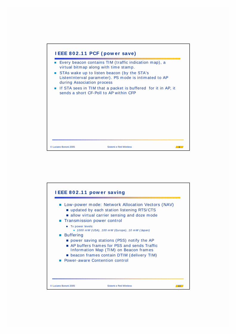
� Every beacon contains TIM (traffic indication map), a virtual bitmap along with time stamp.
� STAs wake up to listen beacon (by the STA’s ListenInterval parameter). PS mode is intimated to AP during Association process
� If STA sees in TIM that a packet is buffered for it in AP, it sends a short CF-Poll to AP within CFP
10© Luciano Bononi 2005 Sistemi e Reti Wireless
IEEE 802.11 power saving
� Low-power mode: Network Allocation Vectors (NAV)� updated by each station listening RTS/CTS� allow virtual carrier sensing and doze mode
� Transmission power control� Tx power levels:
� 1000 mW (USA), 100 mW (Europe), 10 mW (Japan)
� Buffering� power saving stations (PSS) notify the AP� AP buffers frames for PSS and sends Traffic
Information Map (TIM) on Beacon frames� beacon frames contain DTIM (delivery TIM)
� Power-aware Contention control

11© Luciano Bononi 2005 Sistemi e Reti Wireless
IEEE 802.11 power saving (ad hoc scenario)
sleep(doze)
active(awake)
ATIM ATIM ATIM
beaconATIMframe
ATIMack
Station B become virtual AP
sleep(doze)
active(awake)power saving state
power saving state
traffic requestacknowledged
traffic exchanged
time
Station A
virtual AP
Beacon Interval (1) Beacon Interval (2) Beacon Interval (3)
(beacons 1,2)
Station B
(beacon 3)virtual AP
12© Luciano Bononi 2005 Sistemi e Reti Wireless
Range Extension between BSS cells and DS
IEEE 802.11: Distribution System(DS)
AP: Access PointBSS: Basic Service SetESS: Extended Service SetDS: Network to transmit packets between BSSs to realize ESSs.
Portal: logical entity to integrate IEEE 802.11 network and the distributionsystem (dedicated device or access point)

13© Luciano Bononi 2005 Sistemi e Reti Wireless
IEEE 802.11 Wireless LAN
� Technical features: 802.11 Base Standard (1997)� 3 PHY (physical) layer definitions:
� FHSS, DSSS, (IR)� 1-2 Mbps� 2.400-2.4835 GHz (unlicensed ISM band)
� Technical features: 802.11 Evolution a and b (1998)� IEEE 802.11a:� extension of performance and range� support voice, data and video applications� data rates: 6, 12, 18, 24, 36, 48, 54 Mbps� DSSS in the 5GHz band
14© Luciano Bononi 2005 Sistemi e Reti Wireless
IEEE 802.11 status
MAC
MIB
DSSS FH IRPHY
WEP
LLC
MAC Mgmt
802.11b5,11 Mbps
802.11g20+ Mbps
802.11a6,9,12,18,24
36,48,54 Mbps
OFDM
802.11isecurity
802.11fInter Access Point Protocol
802.11eQoS enhancements

15© Luciano Bononi 2005 Sistemi e Reti Wireless
IEEE 802.11 Standard PHY and MAC
2.4 GHz radioFreq. Hopping
Spread Spectrum
2.4 GHz radioDirect
SequenceSpread
Spectrum
Infra-Red
1 Mbit/s2 Mbit/s
2 Mbit/s1 Mbit/s
1 Mbit/s2 Mbit/s
Legend: italic (and red) = optional
Higher data rate extension in 2.4 GHz
802.11b
Higher data rate extension in 5 GHz802.11a
11 & 5.5Mbit/s
6-12-18...54Mbit/s
Single MAC protocol
16© Luciano Bononi 2005 Sistemi e Reti Wireless
Tecnologie e Standard (1)
Mobilità
InternoPremise
Ufficio
Esterno
veicolo
pedestre
statico
0.5 Mbps 2 Mbps 50 Mbps 155 400 Mbps
WPANIEEE
802.15.1Bluetooth
WLANWi-Fi: IEEE 802.11
HiperLAN1, IEEE 802.11a (5Ghz)IEEE 802.11b/g (2.4 Ghz)
(1-108 Mbps)
WWANIEEE 802.20 MBWA
HiperMAN
WMAN WiMAXIEEE 802.16
BWA
250 Km/h
Satellite
PCS: GSM
TDMA IS-136
CDMA IS-95
HSCSD GPRSEDGE
CDMA IS-95B
UMTS
WCDMA - WTDMA
CDMA2000 (1X-3X)
CDPD
1G 2G 2.5G 3G
Euro
paU
SAA
sia/
Pac .
Gia
ppon
e NMTTACSAMPSJTACSNTTC
EL
LU
LA
RE
LAST MILE LMDS MMDS
WPAN802.15.3a
UWB
bitrate
Mobilità
InternoPremise
Ufficio
Esterno
veicolo
pedestre
statico
0.5 Mbps 2 Mbps 50 Mbps 155 400 Mbps
WPANIEEE 802.15.1
(Bluetooth)WLAN
Wi-Fi: IEEE 802.11HiperLAN1, IEEE 802.11a (5Ghz)
IEEE 802.11b/g (2.4 Ghz)(1-108 Mbps)
WWANIEEE 802.20 MBWA
HiperMAN
WMAN WiMAXIEEE 802.16
BWA
250 Km/h
Satellite
PCS: GSM
TDMA IS-136
CDMA IS-95
HSCSD GPRSEDGE
CDMA IS-95B
UMTS
WCDMA - WTDMA
CDMA2000 (1X-3X)
CDPD
1G 2G 2.5G 3G
Euro
paU
SAA
sia/
Pac .
Gia
ppon
e NMTTACSAMPSJTACSNTTC
EL
LU
LA
RE
LAST MILE LMDS MMDS
WPAN802.15.3a
UWB
bitrate
802.15.4(ZigBee)

17© Luciano Bononi 2005 Sistemi e Reti Wireless
Tecnologie e Standard (2)
Gruppi di standardizzazione IEEE 802.11 Descrizione
IEEE 802.11 lo standard originale: bitrate da 1 a 2 Mbps, spettro 2.4 Ghz, livello fisico sia radio che infrarosso
IEEE 802.11a 54 Mbit/s, 5 GHz, lanciato nel 2001
IEEE 802.11b sviluppo di IEEE 802.11 (1999), da 5.5 a 11 Mbps
IEEE 802.11d estensioni per roaming internazionale
IEEE 802.11e estensioni per qualità del servizio
IEEE 802.11f standard per Inter Access Point Protocol (IAPP[2])
IEEE 802.11g 54 Mbit/s, 2.4 GHz, retrocompatibile con IEEE 802.11b
IEEE 802.11h selezione dinamica dei canali e controllo della potenza trasmissiva (compatibile con direttive europee)
IEEE 802.11i integrazioni e estensioni per la sicurezza (2004)
IEEE 802.11j estensioni per direttive giapponesi
IEEE 802.11k estensioni per misurazione dei parametri radio
IEEE 802.11n estensioni per throughput elevati (oltre 200 Mbps) mediante tecnologia MIMO (trasmettitori e ricevitori multipli)
IEEE 802.11p accesso wireless per sistemi veicolari (WAVE)
IEEE 802.11r estensioni per roaming veloce
IEEE 802.11s estensioni per reti wireless mesh
IEEE 802.11t metodi e metriche per misurazione e predizione delle prestazioni
IEEE 802.11u internetworking con reti non 802.11 (cellulari)
IEEE 802.11v gestione e amministrazione delle reti wireless
18© Luciano Bononi 2005 Sistemi e Reti Wireless
Tecnologie e Standard (3)
UWB Bluetooth Wi-fi Wi-fi Wi-fi WiMAX WiMAX EDGE CDMA UMTS
Standard 802.15.3a 802.15.1 802.11a 802.11b 802.11g 802.16d 802.16e 2,5G 3G 3G
contesto WPAN WPAN WLAN WLAN WLAN WMAN (fisso)
WMAN (mobile)
WWAN WWAN WWAN
MAX bitrate
110-480 Mbps
720 Kbps 54 Mbps 11-22 Mbps
54-108 Mpbs
75 Mbps (20 Mhz)
30 Mbps (10 Mhz)384 Kbps 2,4 Mbps 10 Mbps
distanza 10 m 10 m 100 m 100 m 100 m 10 km 5 km 5 km 5 km 5 km
spettro 7,5 Ghz 2,4 Ghz (ISM)
5 Ghz 2,4 Ghz (ISM)
2,4 Ghz (ISM)
11 Ghz 2-6 Ghz 1800 Mhz
multi multi

19© Luciano Bononi 2005 Sistemi e Reti Wireless
Hiperlan/2
� European Telecommunications Standardisation Institute [ETSI] specification
� Broadband Radio Access Networks [BRAN] project
� Hiperlan/2 Global Forum [H2GF]:� open industry forum to create a global standard for
high speed WLAN products
20© Luciano Bononi 2005 Sistemi e Reti Wireless
What is HiperLAN/2?
� A next generation Wireless LAN technology� Operates in the 5 GHz band, with a portion
of dedicated spectrum allocated world-wide� Broadband communication, up to 54
Mbit/s transmission rate at radio interface� Connection-oriented with support for QoS

21© Luciano Bononi 2005 Sistemi e Reti Wireless
HiperLAN/2 - The Vision
Roaming
Airport
Hotel & Conference
Publicspace
Office
Home
Trainstation
Wide area Cellular Datacom
Local Area WLAN Datacom
HiperLan/2 Global Forum
22© Luciano Bononi 2005 Sistemi e Reti Wireless
Goals
� Certified interoperable products on the market early 2002
� Corporate and public networks as the first target� Ensure spectrum allocated on all major markets� Wireless LAN = HiperLAN/2

23© Luciano Bononi 2005 Sistemi e Reti Wireless
Hiperlan/2
� Timetable:� final specification: Sept. 1999� test: year 2000� first product: year 2001 (full market:
year 2002)
� World-wide market estimate for WLAN products[H2GF]:
� $ 1 Bn (year 2000)� $ 2 Bn (year 2002) (not counting embedded
solutions)
24© Luciano Bononi 2005 Sistemi e Reti Wireless
Hiperlan/2
� The Hiperlan/2 network architecture:
Fixed Network (e.g. a LAN)
Access Point (AP) Mobile Terminal (MT)
The Hiperlan/2 radio network
25© Luciano Bononi 2005 Sistemi e Reti Wireless
Hiperlan/2
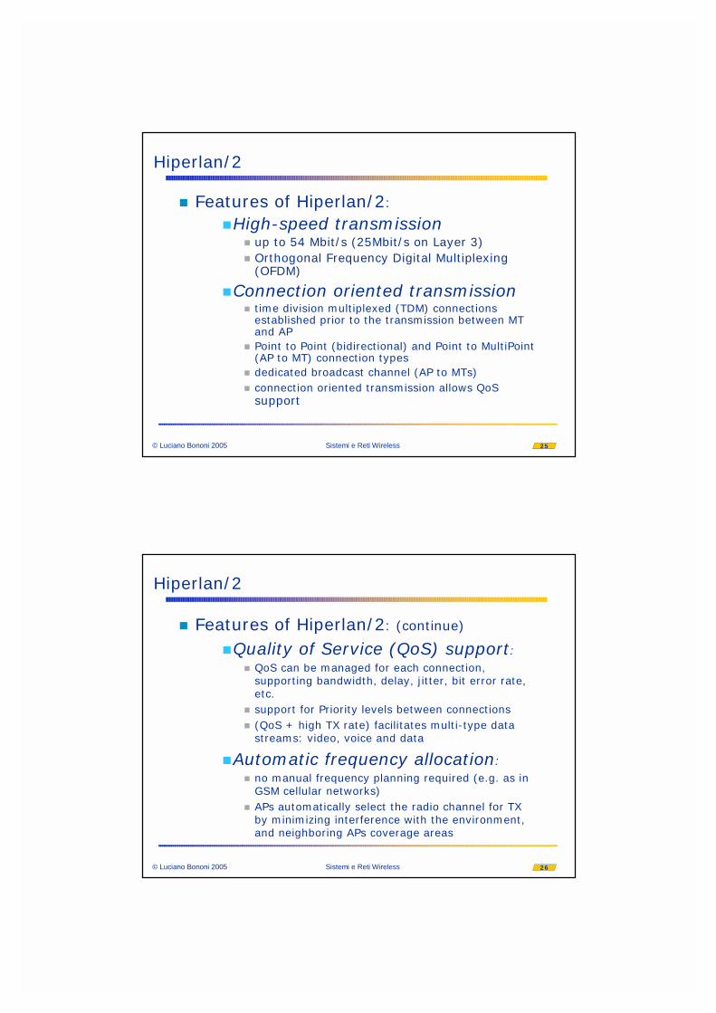
� Features of Hiperlan/2:
�High-speed transmission� up to 54 Mbit/s (25Mbit/s on Layer 3)� Orthogonal Frequency Digital Multiplexing
(OFDM)
�Connection oriented transmission� time division multiplexed (TDM) connections
established prior to the transmission between MT and AP
� Point to Point (bidirectional) and Point to MultiPoint (AP to MT) connection types
� dedicated broadcast channel (AP to MTs)� connection oriented transmission allows QoS
support
26© Luciano Bononi 2005 Sistemi e Reti Wireless
Hiperlan/2
� Features of Hiperlan/2: (continue)
�Quality of Service (QoS) support:� QoS can be managed for each connection,
supporting bandwidth, delay, jitter, bit error rate, etc.
� support for Priority levels between connections� (QoS + high TX rate) facilitates multi-type data
streams: video, voice and data
�Automatic frequency allocation:� no manual frequency planning required (e.g. as in
GSM cellular networks)� APs automatically select the radio channel for TX
by minimizing interference with the environment, and neighboring APs coverage areas

27© Luciano Bononi 2005 Sistemi e Reti Wireless
Hiperlan/2
� Features of Hiperlan/2: (continue)
�Security support:� MT association with the AP covering the area� Authentication supported (provided some directory
service function)� Encryption supported against eaves-dropping and
attacks
�Mobility support:� Handover (defined on a best SNR policy): packet
loss and re-association can occur
28© Luciano Bononi 2005 Sistemi e Reti Wireless
Hiperlan/2
� Features of Hiperlan/2: (continue)
� Network and Application independency:� Hiperlan/2 protocol stack is flexible� can be used as “last hop” wireless segment of Ethernet,
or access network to 3G cellular network� All apps. running over a fixed infrastructure are supported
� power save:� MT-initiated negotiation of sleep (low energy) periods� AP bufferizes traffic to sleeping MT and manages Wake-up
signals

29© Luciano Bononi 2005 Sistemi e Reti Wireless
Hiperlan/2
� Hiperlan/2 protocol architecture:� Convergence layer (CL)� Data Link Control (DLC)
� Association Control Function (ACF)� DLC user Connection Control (DCC)� Radio Resource Control (RRC)� Error Control (EC)
� Physical (PHY)
PHY layer
MAC sublayerTransport channels
Logical channels
RRC ACF DCCEC
RLC (radio link control)
Data Link Control (DLC) layer
Convergence Layer (CL)
30© Luciano Bononi 2005 Sistemi e Reti Wireless
Hiperlan/2
� Convergence layer (CL):� adapts service request from upper layers to
the service offered by DLC� converts higher layer packets to fixed size
packets used within the DLC� makes Hiperlan/2 suitable as radio access
network for a diversity of fixed networks:� Ethernet, IP-based, UMTS, etc. (packet based
CL) � ATM (cell-based CL)
31© Luciano Bononi 2005 Sistemi e Reti Wireless
Hiperlan/2
� MAC sublayer� Logical Transport Channels: on top Transport Channels� SBCH: slow broadcast channel (downlink)
� encryption seeds, handover acks, MAC-id to new assoc. MTs
� DCCH: dedicated control channel (bidirectional)� signalling for connection control and association
� UDCH: user data channel (bidirectional)� user data PDUs, ARQ (acks), reliable ordered delivery for
Convergence Layer CL
� LCCH: link control channel (bidirectional)� info for Error Control (EC) in UDCH
� ASCH: association control channel (uplink)� (re)association request during handover by MTs
32© Luciano Bononi 2005 Sistemi e Reti Wireless
Hiperlan/2
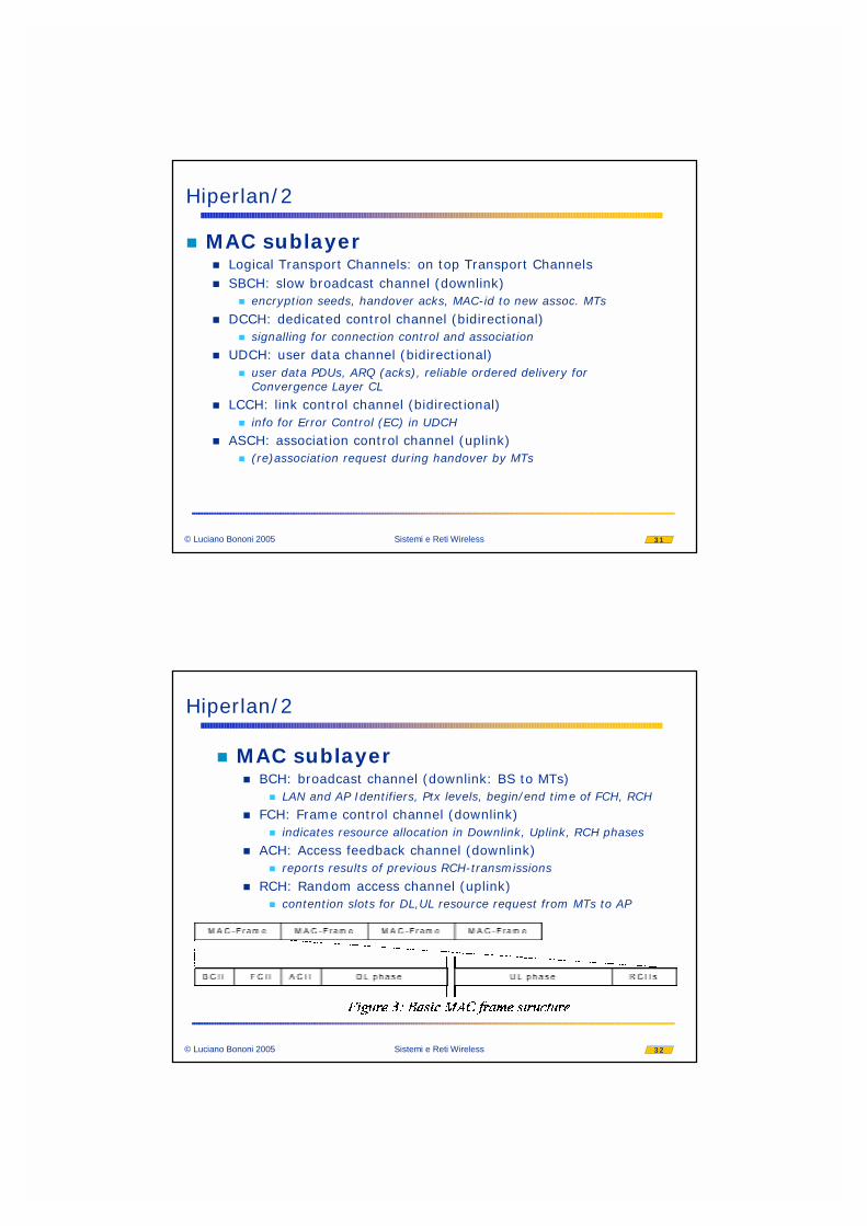
� MAC sublayer� BCH: broadcast channel (downlink: BS to MTs)
� LAN and AP Identifiers, Ptx levels, begin/end time of FCH, RCH
� FCH: Frame control channel (downlink)� indicates resource allocation in Downlink, Uplink, RCH phases
� ACH: Access feedback channel (downlink)� reports results of previous RCH-transmissions
� RCH: Random access channel (uplink)� contention slots for DL,UL resource request from MTs to AP

33© Luciano Bononi 2005 Sistemi e Reti Wireless
Hiperlan/2
� MAC sublayer� Uplink UL,downlink DL (bidirectional)
� sequence of PDU trains� DLC user PDU (U-PDU): 54 Bytes (48 Bytes payload)
� referred to as Long transport CHannel (LCH)
� DLC control PDU (C-PDU): 9 Bytes� referred to as Short transport CHannel (SCH)
34© Luciano Bononi 2005 Sistemi e Reti Wireless
Hiperlan/2
� MAC sublayer: the RCH contention based access (MT to BS)� Two Elimination phases
yield Backoff
blue station start TX
green and blue survive and backoff
red & yellow detect green and blue yield and stop

35© Luciano Bononi 2005 Sistemi e Reti Wireless
Hiperlan/2
� Association and transmission
AP MT
Unique ID (AP scope) for each DLC connection
Association request
Resource request (K u-pdu waiting)
contention slots of RCH
poll/resource grant for each DLC connection
36© Luciano Bononi 2005 Sistemi e Reti Wireless
Hiperlan/2
� PHY layer: data rates� OFDM: Orthogonal Frequency Division
Multiplexing� good for highly dispersive channels� channel spacing 20Mhz
� high bit rate per channel� 19 channels in Europe’s spectrum� 52 subcarriers per channel (48xData, 4xpilot)

37© Luciano Bononi 2005 Sistemi e Reti Wireless
Hiperlan/2
� Single cell coverage area:� 30 meters (indoor), 150 meters (outdoor)
� Spectrum allocation: in 5 GHz band� world-wide roaming in 5.15 - 5.25 GHz
Hiperlan 5.15-5.35
EUROPE
JAPAN
US
High Speed Wireless Access 5.15-5.25
Hiperlan 5.470-5.725
U-NII 5.15-5.35 U-NII 5.725-5.825
GHz
38© Luciano Bononi 2005 Sistemi e Reti Wireless
Hiperlan/2
� Example applications:� Corporate LAN:
� extension (last segment) of Ethernet LAN and IP routers
� Hot Spots: airports, hotels, conference sites
� access to 3G cellular networks� covering hot spots and Wide areas with W-CDMA
� Home network:� wireless infrastructure for home devices� QoS and high-speed support video streams and
datacom applications

39© Luciano Bononi 2005 Sistemi e Reti Wireless
Hiperlan/2
� Performance test:� influenced by number of frequencies,
propagation, interference, link adaptation, etc.
� Office environment test:� < 20Mbps [ETSI requirement] (no link
adaptation)� up to 35 Mbps (with link adaptation)
� Exhibition hall:� > 20 Mbps (with link adaptation)
40© Luciano Bononi 2005 Sistemi e Reti Wireless
IEEE 802.11 vs. HiperLANCharacteristic 802,11 802.11b 802.11a HiperLAN/2Spectrum 2.4 GHz 2.4 GHz 5 GHz 5 GHz~Max physical rate 2 Mb/s 11 Mb/s 54 Mb/s 54 Mb/s~Max data rate, layer 3 1.2 Mb/s 5 Mb/s 32 Mb/s 32 Mb/sMedium access control/Media sharing
Central resource control/ TDMA/TDD
Connectivity Conn.-less Conn.-less Conn.-less Conn.-orientedMulticast Yes Yes Yes Yes1
QoS support (PCF)2 (PCF)2 (PCF)2 ATM/802.1p/RSVP/ DiffServ (full control)
Frequency selection Frequency-hopping or DSSS
DSSS Single carrier Single carrier with Dynamic Frequency Selection
Authentification No No No NAI/IEEE address/X.509Encryption 40-bit RC4 40-bit RC4 40-bit RC4 DES, 3DESHandover support (No)3 (No)3 (No)3 (No)4
Fixed network support Ethernet Ethernet Ethernet Ethernet, IP, ATM, UMTS, FireWire, PPP5
Management 802.11 MIB 802.11 MIB 802.11 MIB HiperLAN/2 MIBRadio link quality control No No No Link adaptation
5. Ethernet supported in first release.
2. Point Control Function, a concept defined in 802.11 to allow certain time slots being allocated for realtime-critical traffic.
1. Two different modes supported, multicast via a dedicated MAC-ID (same as for 8202.11) and N*unicast for improved quality.
Carrier sense - CSMA/CA
3. Requires signalling over the fixed network, which is still proprietary. 4. Requires signalling over the fixed network, to be specified by H2GF.