Embed Size (px)
Citation preview

ENGINEERING FOR RURAL DEVELOPMENT Jelgava, 26.-28.05.2021.
1648
IDENTIFICATION OF ELECTRO-HYDRAULIC LOAD-SENSING SERVO SYSTEM
Alexander Mitov, Tsonyo Slavov, Jordan Kralev, Ilcho Angelov
Technical University of Sofia, Bulgaria
[email protected], [email protected]
Abstract. The paper presents the results of the identification procedure for obtaining a model of an electro-
hydraulic load-sensing servo position system for power steering of mobile machinery. The studied system consists
of an axial-piston variable displacement pump that supplies the load-sensing electro-hydraulic power steering
system. The pump is equipped with a hydro-mechanical pressure controller type DR, which makes it possible to
realize a meter-in flow control circuit with the load-sensing function. When the external resistance force acting on
the cylinder piston increases, the pump controller limits the displacement volume, and hence the flow rate supplied
to the system. The purpose of the identification is to reach a linear state-space model that accurately describes the
dynamic behaviour of the system. The system is represented with one input and two outputs. The output signals
are measurable variables: the spool position in the proportional valve and the piston position of the servo cylinder.
To evaluate the parameters of the model, open-loop experiments were performed with the studied system, which
was realized on a laboratory test rig. The input signal for identification experiment is a random binary signal (RBS)
to achieve good excitation of the plant. Validation of the model obtained has been carried out based on independent
data-set. The aim of the present work is to reach a model that is suitable for the design of embedded controllers
for the electro-hydraulic load-sensing servo systems.
Keywords: system identification, electro-hydraulic, load-sensing, servo system.
Introduction
In recent years, the development of the hydraulic drive systems is mainly focused on increasing
their energy efficiency. One approach to achieve this aim is by introducing a sensitivity to varying in
the external load, which acts on the actuator devices [1]. This approach is primarily applicable to mobile
technology, as the energy efficiency of the hydraulic system is directly related to fuel consumption.
From the point of view of the way of flow control in the load-sensing (LS) systems there are two main
strategies: meter-in or meter-out flow control circuit. Assuming that in both strategies a variable
displacement pump is used, they differ in the way of distribution in the LS valve and the place of its
connection. The first type of this flow control valve, its throttling element (orifice or spool type) is
connected to the inlet port of the valve for automatically maintaining a constant pressure drop (pre-
compensated valve). The second type is carried out by the same components, but the throttling element
is connected to the outlet of the valve for maintaining a constant pressure drop (post-compensated valve).
The connection of the LS shuttle is essential for the functionality of these systems. There are also hybrid
LS systems, which are a combination of the above varieties.
In the load-sensing hydraulic drive systems of mobile machines, the LS valve can be integrated not
only in the manifold controlling the working movements of the machine, but also in the hydraulic
steering unit, thus providing a load-sensitive function of the steering system. In steering systems, this
valve is called a LS resolver or flow rate amplifier. On the other hand, the introduction of digital control
in the steering systems of mobile machines together with their load-sensing allow to achieve even greater
efficiency of the entire hydraulic drive system, which is the main consumer of energy, as it serves the
movement, working and steering function of the machine. Another reason for the introduction of digital
control is the need for precise remote control of mobile machines. This requires the introduction of
different types of feedback for measurable variables in the steering system. These feedbacks guarantee
a better performance of the closed-loop control system. The basis of this type of system is a multivariable
embedded controller, which unlike conventional ones, determines the parameters of the electrical
control signal supplied to the electro-hydraulic control module (EHCM), providing pilot digital control.
This module is practically an electro-hydraulic converter between the microcontroller and the hydraulic
power steering system.
In previous studies, the authors have investigated the workability and control performance of the
electro-hydraulic power steering system (EHPS) without the load-sensing function, which is powered
by a fixed displacement pump and an external priority valve. The possibility to develop EHPS with
higher energy efficiency motivates the authors to begin series of studies of embedded control systems
for load-sensing EHPS, in which the performance strongly depends on the embedded controller. For this
DOI: 10.22616/ERDev.2021.20.TF356

ENGINEERING FOR RURAL DEVELOPMENT Jelgava, 26.-28.05.2021.
1649
purpose, a new, different architecture of EHPS with LS function has been developed, which is
implemented by a variable displacement axial-piston pump equipped with a hydro-mechanical pressure
controller (type DR), electro-hydraulic control block (EHCB) with built-in not only the priority valve,
but also the LS resolver (LS valve). In essence, a meter-in flow control circuit is implemented. The
inclusion of EHCB in conventional hydro-mechanical steering allows the automation of older generation
mobile machines, while improving their energy efficiency.
In contrast to the studied EHPS, current development uses feedback on a steering cylinder piston
position, position of the spool in the proportional valve and the flow rate supplying the EHCB, which
does not participate directly in the control task, but allows to perform an energy analysis of the entire
electro-hydraulic steering system.
Before a design of embedded controller, it is necessary to study a suitable mathematical model [2].
Due to the complex architecture of the system and the presence of complex relation between the
elements in hydraulic devices (which lead to nonlinearities), the authors use the system identification
“black box” approach [3; 4] to evaluate a model suitable for the synthesis of robust controllers in
subsequent developments. The main purpose of this article is to present the results of the identification
procedure performed on the experimental data obtained from a new type of EHPS. For the purposes of
experimental investigation, the authors have developed the electrohydraulic system through a new
laboratory test rig.
Hardware layout for identification
• Electro-hydraulic servo position system.
The chosen approach for identification in order to obtain an adequate “black box” type
mathematical model of the studied load-sensing electro-hydraulic servo system requires experimental
investigation for measuring a data-set [5]. For this purpose, the authors have designed and developed a
new laboratory test rig for implementation of the studied system. The architecture of the electro-
hydraulic system is shown in Fig. 1. The source of hydraulic energy in the developed system is a variable
displacement axial-piston pump 3 equipped with a hydro-mechanical pressure controller (type DR) 4.
The pump supplies the conventional hydrostatic steering unit 11 (type closed-centre no reaction).
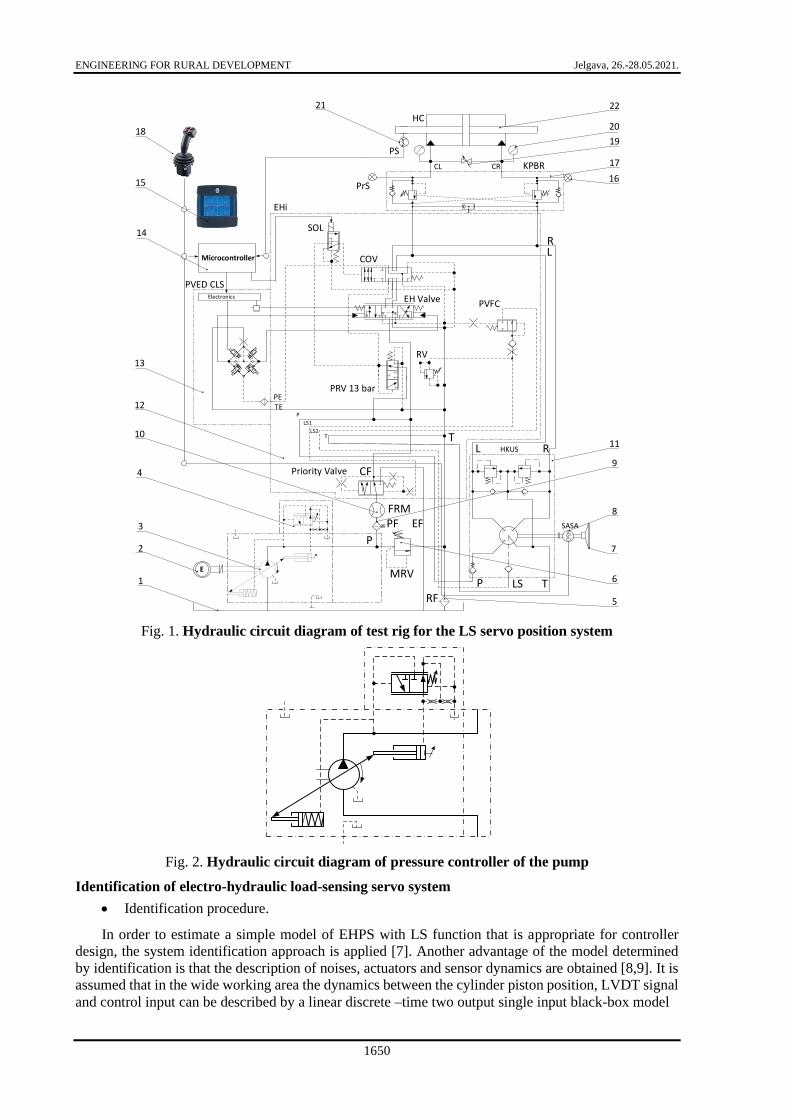
Hydraulic schematic solution of a well-known controller is shown in Fig. 2. EHCB 12 is connected to
the steering unit, which is pilot operated by the EHUM 13 (type PVE) [6]. The EHCB 12 has a built-in
pilot operated proportional spool valve with tracking function, which controls the piston position of a
double-acting hydraulic servo cylinder 22. The cylinder piston serves to drive a steerable axis like in
modern mobile machines. In order to realize different load disturbances, a hydraulic block 17 with over-
centre valves is included, enabling different pressures to be maintained in the both working chambers
of the cylinder during the movement of its piston. The pressure is measured by manometers 20 and by
sensors 16 for dynamic recording. The maximum value of the pressure in the system is limited both by
the pump controller 4 and by the main direct operated pressure-relief valve 6. The pilot pressure in
EHCM is 13bar and is supported by three-way pressure reducing valve (PRV) integrated in EHCB 12.
The system allows operation in three main modes in terms of generating a control action: mechanical
mode (via the steering wheel 7), digital mode (via the electronic joystick 18) and combined mode, which
achieves a variable steering ratio from the steering wheel to the steering cylinder, resp. the steer axle of
the machine. The setting of the various modes is done by switching a mode selection solenoid valve
(SOL), which serves for pilot hydraulic control of the main mode selection valve (COV). The load-
sensing (meter-in) function is performed by the integrated LS resolver valve (PVFC).
In digital mode, the control voltage signal to the EHCM can also be generated by a programmable
industrial controller 14, which has an embedded control algorithm.
In contrast to the EHPS studied in previous works, this system uses feedback on the piston position
21 of the steering cylinder, on the position of the spool (PVED CLS – LVDT) of the proportional valve
and flow rate feedback, which is not directly involved in the control task, but allows to perform an
energy analysis of the entire electro-hydraulic steering system. For this reason, the flow rate signal
measured by a gear flow meter 10 showing the flow rate from the variable displacement pump 3 is also
included in the identification data set, and the actual flow rate consumed by the EHSU depends on the
priority valve (line CF).
ENGINEERING FOR RURAL DEVELOPMENT Jelgava, 26.-28.05.2021.
1650
Electronics
E
RL HKUS
SASA
Microcontroller
P LS T
P
T
P
LS1
LS2T
PRV 13 barPETE
RV
EH Valve
COV
SOL
EHi
PVED CLS
PVFC
Priority Valve
KPBR
RL
CL CR
EF
CF
FRMPF
MRV1
12
RF
2
3
4
10
13
14
15
18
21 22
19
17
11
9
8
6
5
7
HC
PS
PrS
20
16
Fig. 1. Hydraulic circuit diagram of test rig for the LS servo position system
Fig. 2. Hydraulic circuit diagram of pressure controller of the pump
Identification of electro-hydraulic load-sensing servo system
• Identification procedure.
In order to estimate a simple model of EHPS with LS function that is appropriate for controller
design, the system identification approach is applied [7]. Another advantage of the model determined
by identification is that the description of noises, actuators and sensor dynamics are obtained [8,9]. It is
assumed that in the wide working area the dynamics between the cylinder piston position, LVDT signal
and control input can be described by a linear discrete –time two output single input black-box model

ENGINEERING FOR RURAL DEVELOPMENT Jelgava, 26.-28.05.2021.
1651
( 1) ( ) ( ) ( ) ( ) ( ) ( )
( ) ( ) ( ) ( ) ( ) ( )
x k A x k B u k K e k
y k C x k D u k e k
+ = + +
= + +, (1)
where x =x[x1 x2 … xn]T – state vector;
u – control signal that is the voltage applied to the control input of PVE;
y =[ yLVDT ypos]T – output signal;
yLVDT – output of the LVDT sensor;
ypos – cylinder piston position;
e(k) =[e1 e2]T – residual vector;
e1 and e2 – residuals respect to the LVDT and cylinder position, respectively);
A, B, C, D and K – matrices with appropriate dimensions and
θ = θ[θ1 θ2 … θn]T – vector of model parameters.
The necessary for identification input-output data are collected in real time via developed by the
authors embedded system for testing of control algorithms that is presented in detail in [10]. The
experiment is performed in accordance with the scheme presented in Fig.3. The input signal is random
binary sequence (RBS) with the amplitude 4000mV . It is well known that the type of the input signal
guarantees the persistent excitation of the plant. Thus, the obtained input-output data can be used for
derivation of the plant model. The experiment sample rate is 100 Hz. Part of measured data are separated
in two data sets. The first one is used for model estimation and the second one is used for model
validation [11]. The estimation data set of length 4500 is presented in Fig. 4.
ELECTRO-HYDRAULIC SERVO
SYSTEM
RBSLVDT
y
pistonyu
Fig. 3. Hydraulic circuit diagram of pressure
controller of the pump
Fig. 4. Estimation data set (y1 –lvdt, y2-
cylinder piston position)
First, we assume that the “true” order of model (1) is between 1 and 10. To reduce the number of
parameters to be estimated, the model (1) is parametrized by observable canonical form. We estimate
model parameters by the prediction error method that minimizes the prediction error [3]
ˆ( ) ( ) ( , )e k y k y k = − . (2)
In equation (2) the vector ˆ( , )y k is the predicted output that is obtained by predictor
ˆ ˆ ˆ( 1, ) ( ) ( , ) ( ) ( ) ( )( ( ) ( ) ( , )),
ˆ ˆ( , ) ( ) ( , )
ex k A x k B u k K y k C x k
y k C x k
+ = + + −
= (3)
where Ke(θ) is a Kalman filter gain, which is determined as a positive definite solution of Riccati
equation.
Appropriate model order is chosen on the basis of the model’s Hankel singular values that is
presented in Fig.5. It seems that the suggested model order is 3rd, but the singular values are negligibly
small for orders higher than 8th. Due to that we estimate models of orders 3, 4, 5 and 8. The logarithmic
amplitude frequency responses of the estimated model are depicted in Fig. 6.

ENGINEERING FOR RURAL DEVELOPMENT Jelgava, 26.-28.05.2021.
1652
Fig. 5. Hankel singular values of estimated
models with orders between 1 and 10
Fig. 6. Logarithmic amplitude frequency
responses of estimated models
As it can be seen, the frequency responses of all estimated models are almost the same and to choose
the appropriate model some validation tests should be performed.
• Model validation.
To confirm that the estimated models are described sufficiently well, dynamics of EHPS and noise,
several validation tests are performed: Correlation test of the model residuals; Test whether there is
significant gain between the residue error and control signal in the frequency domain. This test is based
on logarithmic amplitude frequency response of the estimated model from the input signal to model
residuals; Akaike predictive error calculated from model residuals,
1
11
( ) ( )
1
NT
k
d
NFPE e k e kdN
N=
+
=
+ , (4)
where d – number of estimated parameters and N is the data length;
Comparison of model output and measured output by index
2
2
100 1 %my y
FITy y
−= −
−
, (5)
where ym – model output and y is the mean of y.
The first two tests are used to decide whether the estimated model parameters are unbiased and
whether the model describes EHPS dynamics sufficiently well. From various models that pass the first
two tests and have almost the same FPE and FIT, the best model is one of the lowest order. In Fig.7 and
Fig 8 the results from the first two tests are presented and in Fig 9 the results obtained by the third test
are depicted. As it can be seen from Fig.7, all models except the one of 3rd order pass residual error tests,
which means that the estimated model parameters of these models are unbiased. Fig.8 shows that the
estimated models are described sufficiently well, but the index FIT for 3rd order model is smaller than
the ones for others models (Fig. 9). The FPE indices for models of 3rd, 4th, 5th and 8th orders are 3 3 3 33.08 10 ,1.87 10 ,1.80 10 ,1.73 10− − − − . Finally, according to the adopted criteria the best model is the
estimated one from the 4rd order. Its matrices take the values
5
0 1 0 0 0.0231 1.5999 0.0031
2.1432 2.1207 1.4618 1.4624 0.4533 1 0 0 0 0 1.7777 0.0084, 10 , , ,
0 0 0 1 0.2308 0 0 1 0 0 0.5023 0.9847
0.3563 0.3524 0.0464 0.9532 0.4971 1.4377 0.986
A B C D K−
− − − − = = = = = − − − − − 6
(6)
and the covariance matrix is 0.0039 0.0007
( )0.0007 0.4739
TM ee−
= −
.

ENGINEERING FOR RURAL DEVELOPMENT Jelgava, 26.-28.05.2021.
1653
Fig. 7. Residual error test of estimated models Fig. 8. Frequency response of estimated
model from input signal to model residuals
Fig. 9. Frequency response of estimated model from input signal to model residuals
Conclusions
The general result of this article is a linear state space model of the electro-hydraulic load-sensing
servo system for power steering of mobile machines. The single input and two outputs models are
obtained by presented in the article system identification procedure based on the experimentally
measured input-output data-set. For the aim of identification, the authors have developed the studied
electro-hydraulic system as a laboratory test rig. The validation of the identified model is based on
several tests, and it was successfully performed. The aim of the authors is to use the evaluated model in
their next developments, which will be focused on the design and implementation of embedded robust
controllers for EHPS with LS. The presented “black box” identification approach can be used for
mathematical description of different types of electro-hydraulic drive.
Acknowledgements
The authors would like to thank the Research and Development Sector at the Technical University
of Sofia for the financial support.
References
[1] Findeisen D., Helduser S. Ölhydraulik, 6. Auflage, Springer-Vieweg, 2015.
[2] Jelali M., Kroll A. Hydraulic Servo-Systems. Modelling, Identification and Control. Springer
London, 2004.
[3] Ljung L. System Identification: Theory for the User. Second edition. Prentice-Hall Inc., Englewood
Cliffs, NJ, 1999.

ENGINEERING FOR RURAL DEVELOPMENT Jelgava, 26.-28.05.2021.
1654
[4] Witters M., Swevers J. Black-box model identification for a continuously variable, electro-
hydraulic semi-active damper, Mechanical Systems and Signal Processing, Vol. 24, 2010, pp. 4-18.
[5] Sjöberg J., Zhang Q., Ljung L., Benveniste A., Delyon B., Glorennec P.-Y., Juditsky A. Nonlinear
black-box modeling in system identification: a unified overview, Automatica, Vol. 31 (12), 1995,
pp. 1691-1724.
[6] Danfoss Inc., Steering, EHi steering valve, Technical Information, BC00000379en-US0202, 2018.
[7] Proca A., Keyhani A. Identification of power steering system dynamic models. – Mechatronics,
Vol. 8, 1998, Elsevier, pp. 255-270.
[8] Ziaei K., Sepehri N. Modeling and identification of electrohydraulic servos. Mechatronics, Vol. 10
(7), 2000, pp.761-772.
[9] Kaddissi C., Kenne J., Saad M. Identification and Real-Time Control of an Electrohydraulic Servo
System Based on Nonlinear Backstepping. Transactions on Mechatronics, 12(1), 2007, pp.12-22.
[10] Mitov Al., Kralev J., Slavov Ts., Angelov Il. Design of H-infinity tracking controller for application
in autonomous steering of mobile machine, 19th International Scientific Conference Engineering for
Rural Development (ERD 2020), Jelgava, Latvia, 2020, pp. 871-876.
[11] Zhao P., Wang S., Li X., Zhang B. A novel method of parameter identification of nonlinear
electrohydraulic servo systems, Proceedings of International Conference on Fluid Power and
Mechatronics, Beijing, 2011, pp. 547-551.