Embed Size (px)
Citation preview
Electro-upsettingUnits for
Forming Technology
2 LASCO Electro-upsetting
LASCO solutions…
Electro-upsetting
In electro-upsetting a high electric current at low frequency is passed through a bar section which is lim-ited by contact electrodes of dif-ferent potential and heated due to high current density and ohmic resistance. Axial force applied by a hydraulic piston simultaneous-ly causes the gathering of volume which results in an increasing dis-tance between the electrodes. At the same time the anvil electrode must retreat to allow space for the increasing volume.
Apart from free and form upset-ting at the bar end material can be gathered at any position along the bar length.
Free upsetting
Form upsetting
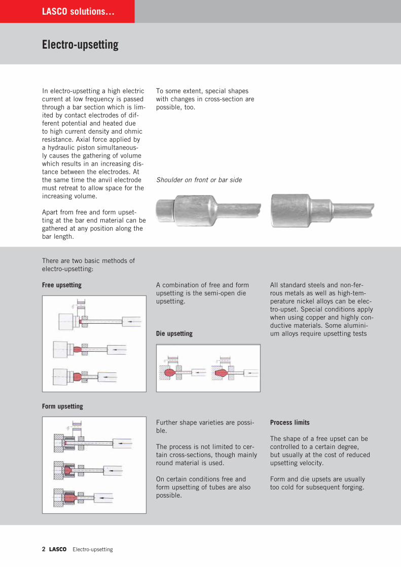
To some extent, special shapes with changes in cross-section are possible, too.
Shoulder on front or bar side
A combination of free and form upsetting is the semi-open die upsetting.
Further shape varieties are possi-ble.
The process is not limited to cer-tain cross-sections, though mainly round material is used.
On certain conditions free and form upsetting of tubes are also possible.
Process limits
The shape of a free upset can be controlled to a certain degree, but usually at the cost of reduced upsetting velocity.
Form and die upsets are usually too cold for subsequent forging.
All standard steels and non-fer-rous metals as well as high-tem-perature nickel alloys can be elec-tro-upset. Special conditions apply when using copper and highly con-ductive materials. Some alumini-um alloys require upsetting tests
There are two basic methods of electro-upsetting:
Die upsetting
Electro-upsetting LASCO 3
...in detail
Preconditions and advantages of electro-upsetting
A conductive surface is neces-sary for an optimum upsetting and heating rate. Appropriate surface quality can be reached by drawing, centerless grinding and peeling.
Milled, sand-blasted or reeled sur-faces have a negative effect on the lifetime of the contact tools and the working speed.
A preferably rectangular end face is a precondition for fault-less material gathering. In cer-tain cases chamfering is advisable. Depending on the bar diameter suitable end faces can be reached by shearing or sawing.
Advantages
By using electro-upsetting some of the well-known technical limitations and disadvantages of mechanical upsetters can be eliminated and the operating efficiency can be increased.
� Simultaneous heating and upsetting in one machine.
� Almost no restrictions of length in one operation.
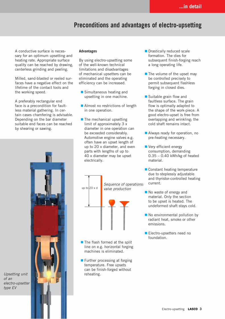
� The mechanical upsetting limit of approximately 3 x diameter in one operation can be exceeded considerably. Automotive engine valves e.g. often have an upset length of up to 20 x diameter, and even parts with lengths of up to 40 x diameter may be upset electrically.
� The flash formed at the split line on e.g. horizontal forging machines is eliminated.
� Further processing at forging temperature. Free upsets can be finish-forged without reheating.
� Drastically reduced scale formation. The dies for subsequent finish-forging reach a long operating life.
� The volume of the upset may be controlled precisely to permit subsequent flashless forging in closed dies.
� Suitable grain flow and faultless surface. The grain flow is optimally adapted to the shape of the work-piece. A good electro-upset is free from overlapping and wrinkling; the cold shaft remains intact.
� Always ready for operation, no pre-heating necessary.
� Very efficient energy consumption, demanding 0.35 – 0.40 kWh/kg of heated material.
� Constant heating temperature due to steplessly adjustable and thyristor-controlled heating current.
� No waste of energy and material. Only the section to be upset is heated. The undeformed shaft stays cold.
� No environmental pollution by radiant heat, smoke or other emissions.
� Electro-upsetters need no foundation.
up to 20 x dSequence of operations: valve production
Upsetting unit of an electro-upsetter type EV
4 LASCO Electro-upsetting
Designs…
LASCO electro-upsetter
LASCO builds electro-upsetters in horizontal and vertical arrangement as well as special designs.
EH = horizontal electro-upsetterEV = vertical electro-upsetter
Another feature of this machine type is the nominal capacity of the transformer.
EH 63 = horizontal electro-upsetter with a nominal transformer capacity of 63 kVA
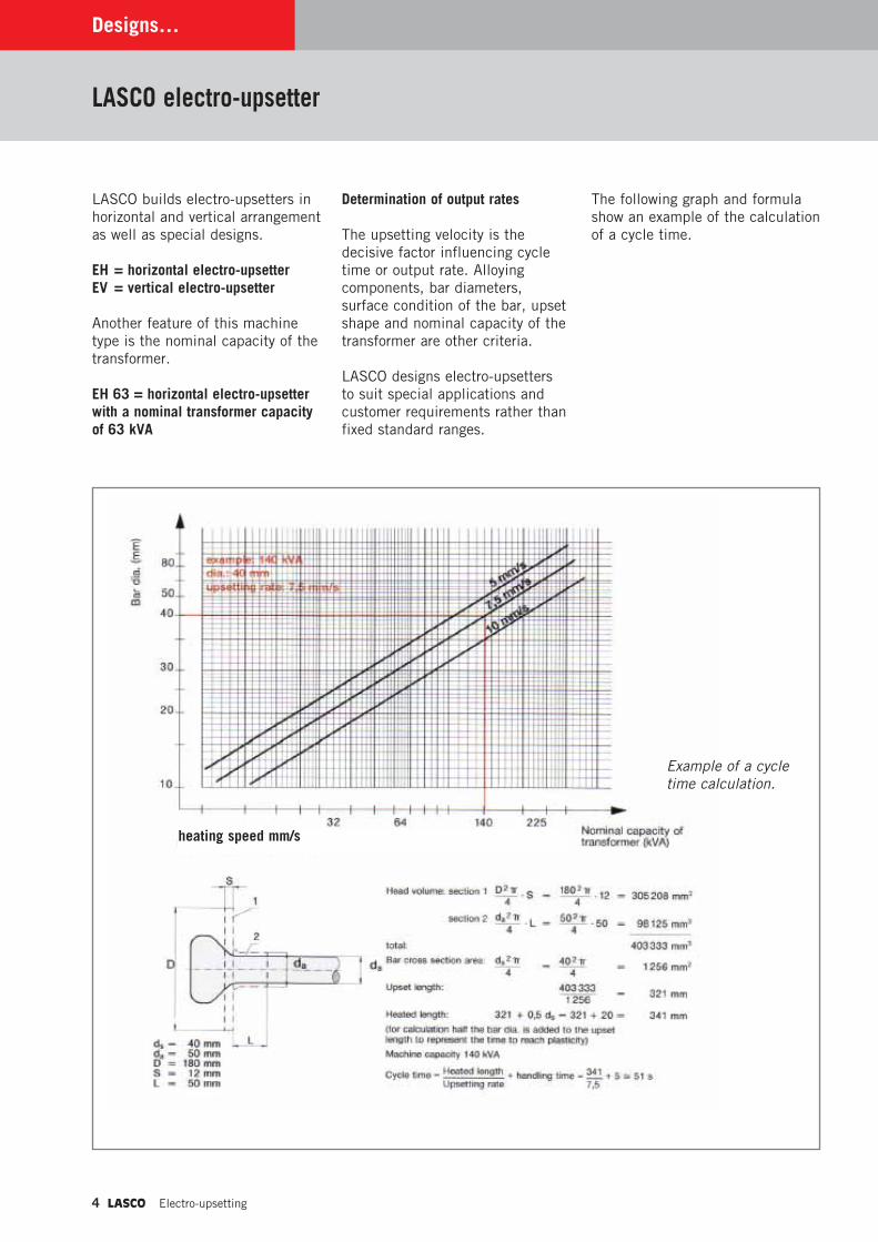
Determination of output rates
The upsetting velocity is the decisive factor influencing cycle time or output rate. Alloying components, bar diameters, surface condition of the bar, upset shape and nominal capacity of the transformer are other criteria.
LASCO designs electro-upsetters to suit special applications and customer requirements rather than fixed standard ranges.
The following graph and formula show an example of the calculation of a cycle time.
Example of a cycle time calculation.
heating speed mm/s
Electro-upsetting LASCO 5
…and options
Operating features and control
After the bar has been placed between the clamping electrodes and the foot switch has been actuated an automatic operating cycle starts.
The clamping electrodes close, the upsetting piston pushes the bar against the anvil plate and the heating current begins to flow when sufficient contact pressure has been reached.
The parameters upsetting and retraction speed as well as heating current are controlled by a servo drive and programmable control independently. Both the upsetting and the retraction stroke of the anvil electrode are divided into various variable sections. The upsetting process can be adapted optimally to the technical requirements.
When the program has finished the work-piece is released.
The programmable logic control system offers the following operating features:
� Operator guidance via colour screen.
� Input and display of process data and functions via foil keyboard.
� Display of operational status and preconditions for start of production.
� Fault messages displayed on a special diagnostic screen.
� Fault warning in clear text.
� System for the acquisition of working data with shift, charge and countdown batch counter. Additionally production and interruption periods are indicated.
� Filing of process data under product numbers.
� Overview of product numbers.
� Availability and modification of product numbers in similar forging processes.
� Profibus-system with diagnostics capability.
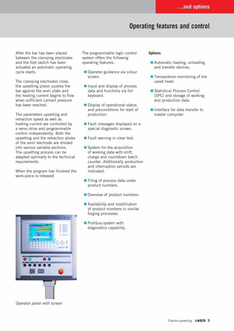
Operator panel with screen
Options
� Automatic loading, unloading and transfer devices.
� Temperature monitoring of the upset head.
� Statistical Process Control (SPC) and storage of working and production data.
� Interface for data transfer to master computer.
6 LASCO Electro-upsetting
LASCO concepts…
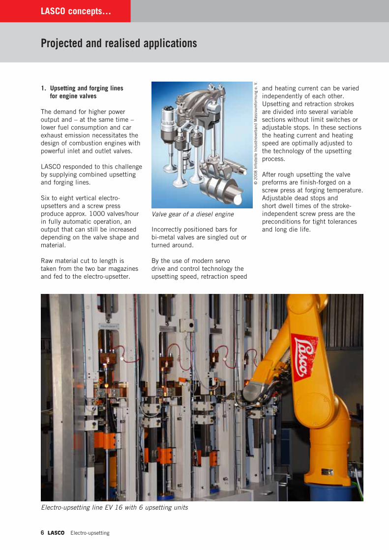
1. Upsetting and forging lines for engine valves
The demand for higher power output and – at the same time – lower fuel consumption and car exhaust emission necessitates the design of combustion engines with powerful inlet and outlet valves.
LASCO responded to this challenge by supplying combined upsetting and forging lines.
Six to eight vertical electro-upsetters and a screw press produce approx. 1000 valves/hour in fully automatic operation, an output that can still be increased depending on the valve shape and material.
Raw material cut to length is taken from the two bar magazines and fed to the electro-upsetter.
Incorrectly positioned bars for bi-metal valves are singled out or turned around.
By the use of modern servo drive and control technology the upsetting speed, retraction speed
and heating current can be varied independently of each other. Upsetting and retraction strokes are divided into several variable sections without limit switches or adjustable stops. In these sections the heating current and heating speed are optimally adjusted to the technology of the upsetting process.
After rough upsetting the valve preforms are finish-forged on a screw press at forging temperature. Adjustable dead stops and short dwell times of the stroke-independent screw press are the preconditions for tight tolerances and long die life.
Projected and realised applications
Valve gear of a diesel engine
Electro-upsetting line EV 16 with 6 upsetting units
© 2
00
8 I
nfos
telle
Ind
ustr
ieve
rban
d M
assi
vum
form
ung
e. V
.
Electro-upsetting LASCO 7
9
6
5
3
4
2
1
8
7
2
1
4
3
5
…in detail
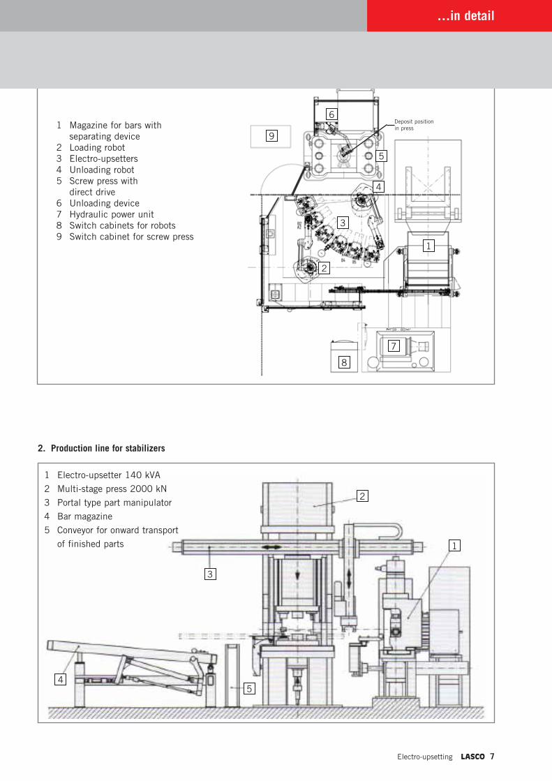
2. Production line for stabilizers
1 Magazine for bars with separating device 2 Loading robot 3 Electro-upsetters 4 Unloading robot 5 Screw press with direct drive 6 Unloading device 7 Hydraulic power unit 8 Switch cabinets for robots 9 Switch cabinet for screw press
1 Electro-upsetter 140 kVA
2 Multi-stage press 2000 kN
3 Portal type part manipulator
4 Bar magazine
5 Conveyor for onward transport
of finished parts
Deposit position in press
8 LASCO Electro-upsetting
LASCO concepts…
Projected and realised applications
High safety requirements for sta-bilizers used in trucks, busses and railway wagons made LASCO design and supply this flexible pro-duction line:
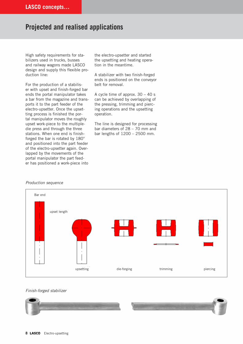
For the production of a stabilis-er with upset and finish-forged bar ends the portal manipulator takes a bar from the magazine and trans-ports it to the part feeder of the electro-upsetter. Once the upset-ting process is finished the por-tal manipulator moves the roughly upset work-piece to the multiple-die press and through the three stations. When one end is finish-forged the bar is rotated by 180° and positioned into the part feeder of the electro-upsetter again. Over-lapped by the movements of the portal manipulator the part feed-er has positioned a work-piece into
the electro-upsetter and started the upsetting and heating opera-tion in the meantime.
A stabilizer with two finish-forged ends is positioned on the conveyor belt for removal.
A cycle time of approx. 30 – 40 s can be achieved by overlapping of the pressing, trimming and pierc-ing operations and the upsetting operation.
The line is designed for processing bar diameters of 28 – 70 mm and bar lengths of 1200 – 2500 mm.
Production sequence
Finish-forged stabilizer
die-forging
Bar end
upset length
upsetting trimming piercing
Electro-upsetting LASCO 9
…in detail
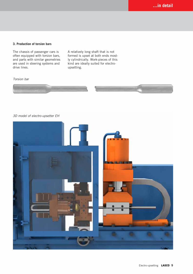
3. Production of torsion bars
The chassis of passenger cars is often equipped with torsion bars, and parts with similar geometries are used in steering systems and drive lines.
Torsion bar
A relatively long shaft that is not formed is upset at both ends most-ly cylindrically. Work-pieces of this kind are ideally suited for electro-upsetting.
3D model of electro-upsetter EH
10 LASCO Electro-upsetting
LASCO concepts…
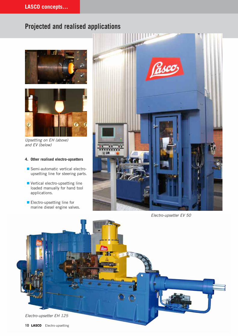
4. Other realised electro-upsetters
� Semi-automatic vertical electro-upsetting line for steering parts.
� Vertical electro-upsetting line loaded manually for hand tool applications.
� Electro-upsetting line for marine diesel engine valves.
Projected and realised applications
Upsetting on EH (above) and EV (below)
Electro-upsetter EV 50
Electro-upsetter EH 125
Electro-upsetting LASCO 11
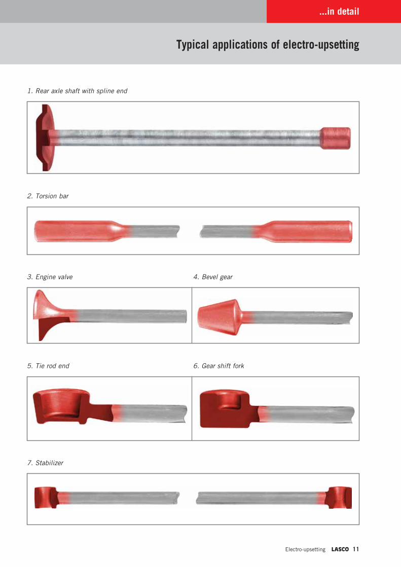
1. Rear axle shaft with spline end
2. Torsion bar
3. Engine valve 4. Bevel gear
5. Tie rod end 6. Gear shift fork
7. Stabilizer
...in detail
Typical applications of electro-upsetting
www.lasco.com
Headquarters:LASCO Umformtechnik GmbHHahnweg 13996450 COBURGGERMANYPhone +49 9561 642-0Fax +49 9561 642-333E-mail [email protected] www.lasco.com
LASCO FRANCE1, allée des Cèdres78860 SAINT NOM LA BRETÈCHEFRANCEPhone +33 1 3080-0528 Fax +33 1 3080-0584 E-mail [email protected]
LASCO USALASCO Engineering Services L.L.C.615 Harbor AvenueMONROE, MI 48162 USAPhone +1 734 241-0094Fax +1 734 241-1316E-mail [email protected] www.lascoUSA.com
LASCO CHINALASCO (Beijing) Forming Technology Co. Ltd.Huateng Tower, Unit 1706AJia 302, 3rd Area of Jinsong,Chaoyang District100021 BEIJINGP.R. CHINAPhone +86 10 8773 0378Fax +86 10 8773 0379E-mail [email protected]
Oct
ober
20
12