Embed Size (px)
Citation preview

S09N-8590-00IBM Mobile Systems
ThinkPad 240 Hardware Maintenance Manual December 2000

i

Before using this information and the product it supports,be sure to read the general information under “Read ThisFirst” on page 1.
Second Edition (October 1999)
The following paragraph does not apply to the UnitedKingdom or any country where such provisions areinconsistent with local law:
INTERNATIONAL BUSINESS MACHINES CORPO-RATION PROVIDES THIS PUBLICATION "AS IS"WITHOUT ANY WARRANTY OF ANY KIND, EITHEREXPRESS OR IMPLIED, INCLUDING, BUT NOT LIMITEDTO, THE LIMITED WARRANTIES OFMERCHANTABILITY OR FITNESS FOR A PARTICULARPURPOSE. Some states do not allow disclaimers orexpress or implied warranties in certain transactions; there-fore, this statement may not apply to you.
This publication could include technical inaccuracies ortypographical errors. Changes are periodically made to theinformation herein; these changes will be incorporated innew editions of the publication. IBM may make improve-ments or changes in the products or the programsdescribed in this publication at any time.
It is possible that this publication may contain referencesto, or information about, IBM products (machines and pro-grams), programming, or services that are not announcedin your country. Such references or information must notbe construed to mean that IBM intends to announce suchIBM products, programming, or services in your country.
Requests for technical information about IBM productsshould be made to your IBM Authorized Dealer or yourIBM Marketing Representative.
Copyright International Business Machines Corpo-ration 1999. All rights reserved. Note to US GovernmentUsers — Documentation related to restricted rights — Use,duplication, or disclosure is subject to restrictions set forthin GSA ADP Schedule Contract with IBM Corp.
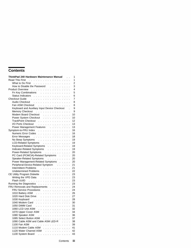
Contents
ThinkPad 240 Hardware Maintenance Manual . . 1Read This First . . . . . . . . . . . . . . . . . . 1
What to Do First . . . . . . . . . . . . . . . . 2How to Disable the Password . . . . . . . . . 3
Product Overview . . . . . . . . . . . . . . . . . 4Fn Key Combinations . . . . . . . . . . . . . 5Status Indicators . . . . . . . . . . . . . . . . 6
Checkout Guide . . . . . . . . . . . . . . . . . 7Audio Checkout . . . . . . . . . . . . . . . . 8Fan ASM Checkout . . . . . . . . . . . . . . 8Keyboard and Auxiliary Input Device Checkout . 9Memory Checkout . . . . . . . . . . . . . . . 9Modem Board Checkout . . . . . . . . . . . . 10Power System Checkout . . . . . . . . . . . . 10TrackPoint Checkout . . . . . . . . . . . . . . 12I/O Ports Checkout . . . . . . . . . . . . . . 13Power Management Features . . . . . . . . . 13
Symptom-to-FRU Index . . . . . . . . . . . . . . 16Numeric Error Codes . . . . . . . . . . . . . . 16Error Messages . . . . . . . . . . . . . . . . 18No Beep Symptoms . . . . . . . . . . . . . . 19LCD-Related Symptoms . . . . . . . . . . . . 19Keyboard-Related Symptoms . . . . . . . . . . 19Indicator-Related Symptoms . . . . . . . . . . 19Power-Related Symptoms . . . . . . . . . . . 20PC Card (PCMCIA)-Related Symptoms . . . . . 20Speaker-Related Symptoms . . . . . . . . . . 20Power Management-Related Symptoms . . . . . 20Peripheral-Device-Related Symptom . . . . . . 21Intermittent Problems . . . . . . . . . . . . . 21Undetermined Problems . . . . . . . . . . . . 22
CE Utility Program Diskette . . . . . . . . . . . . 23Writing the VPD Data . . . . . . . . . . . . . 23Flash UUID . . . . . . . . . . . . . . . . . . 23
Running the Diagnostics . . . . . . . . . . . . . . 23FRU Removals and Replacements . . . . . . . . . 24
FRU Service Procedures . . . . . . . . . . . . 241010 Battery ASM . . . . . . . . . . . . . . . 261020 Hard Disk Drive . . . . . . . . . . . . . 271030 Keyboard . . . . . . . . . . . . . . . . 281040 Modem Card . . . . . . . . . . . . . . . 301050 DIMM Card . . . . . . . . . . . . . . . 311060 LCD Unit ASM . . . . . . . . . . . . . . 321070 Upper Cover ASM . . . . . . . . . . . . 341080 Speaker ASM . . . . . . . . . . . . . . 361085 Select Button ASM . . . . . . . . . . . . 371090 Cable ASM and Cable ASM LED-R . . . . 381100 Fan ASM . . . . . . . . . . . . . . . . 391110 Modem Cable ASM . . . . . . . . . . . . 411120 Water Channel ASM . . . . . . . . . . . 421130 System Board . . . . . . . . . . . . . . 43
Contents iii

1135 Rear Bracket . . . . . . . . . . . . . . . 451140 PCMCIA Slots . . . . . . . . . . . . . . 461150 LCD Bezel ASM . . . . . . . . . . . . . 471160 LCD Inverter ASM . . . . . . . . . . . . 481170 LCD Panel ASM (LCD Type A and B) . . . 491180 LCD FPC ASM (LCD Type A) . . . . . . . 511185 LCD FPC ASM (LCD Type B) . . . . . . . 521190 Hinge ASM . . . . . . . . . . . . . . . 53
Computer Parts Listing . . . . . . . . . . . . . . 54LCD Unit Parts Listing (LCD Type A) . . . . . . . . 58LCD Unit Parts Listing (LCD Type B) . . . . . . . . 59Service Tools . . . . . . . . . . . . . . . . . . . 59Notices . . . . . . . . . . . . . . . . . . . . . . 61Trademarks . . . . . . . . . . . . . . . . . . . 61
iv ThinkPad 240

ThinkPad 240 HardwareMaintenance Manual
About This Manual
This manual contains service and reference information forthe IBM ThinkPad 240 products. Use this manual alongwith the diagnostics tests to troubleshoot problems effec-tively.
There are two models of LCD panel used with theThinkPad 240: LCD Type A and LCD Type B. Check thelast five letters of the unit's serial number you are servicingto determine the model.
LCD Type A:
All ThinkPad 240 computers that have serial numberswhose last five alphanumeric characters are "00001" to"YZZZZ" are fitted with Type A panels.
Note: The number range is from 00001 to 99999, and theletter range is from AAAAA to YZZZZ.
LCD Type B:
All ThinkPad 240 computers that have serial numberswhose last five letters are "ZAAAA" to "ZZZZZ" are fittedwith Type B panels.
The servicer need only check the fifth letter from the end.If the fifth letter from the end is "0 — Y" (inclusive), thenthe LCD panel is Type A. If the fifth letter from the end is"Z", then the LCD panel is Type B.
The manual is divided into sections as follows:
� The introduction section provides general information,guidelines, and safety information required to servicecomputers.
� The product-specific section includes service, refer-ence, and product-specific parts information.
This manual is intended for trained servicers who arefamiliar with ThinkPad products. Use this manual alongwith the PC Doctor to troubleshoot problems effectively.
Read This FirstBefore you go to the checkout guide, be sure to read thissection.
Important Notes
� Only certified trained personnel should servicethe computer.
� Read the entire FRU service procedures beforereplacing any FRUs.
ThinkPad 240 1

� Use new nylon-coated screws when you replaceFRUs.
� Be extremely careful during write operations suchas copying, saving, or formatting. Drives in thecomputer that you are servicing might have beenrearranged or the drive startup sequence might havebeen altered. If you select an incorrect drive, data orprograms might be overwritten.
� Replace FRUs only for the correct model. Whenyou replace a FRU, make sure the model of the com-puter and FRU part number are correct by referring tothe FRU parts list.
� A FRU should not be replaced because of asingle, unreproducible failure. Single failures canoccur for a variety of reasons that have nothing to dowith a hardware defect, such as: cosmic radiation,electrostatic discharge, or software errors. FRUreplacement should be considered only when a recur-ring problem exists. If this is suspected, clear theerror log and run the test again. Do not replace anyFRUs if log errors do not reappear.
Be careful not to replace a non-defective FRU.
What to Do FirstThe servicer must include the following in the partsexchange form or parts return form that is attached to thereturned FRU:
1. Name and phone number of servicer
2. Date of service
3. Date when part failed
4. Date of purchase
5. Failure symptoms, error codes appearing on thedisplay, and beep symptoms
6. Procedure index and page number in which the failingFRU was detected
7. Failing FRU name and part number
8. Computer type, model number and serial number
9. Customer's name and address
Before checking problems with the computer, determinewhether or not the damage applies to the warranty byreferring to the following:
Note for Warranty: During the warranty period, the cus-tomer may be responsible for repair costs if the computerdamage was caused by misuse, accident, modification,unsuitable physical or operating environment, or impropermaintenance by the customer. The following list providessome common items that are not covered under warranty
2 ThinkPad 240

and some symptoms that may indicate that the systemwas subjected to stresses beyond normal use:
The following is not covered under warranty:
� LCD panel cracked by applying excessive force orfrom being dropped
� Scratched (cosmetic) parts
� Cracked or broken plastic parts, broken latches,broken pins, or broken connectors caused by exces-sive force
� Damage caused by liquid spilled into the system
� Damage caused by the improper insertion of a PCCard or the installation of an incompatible card
� Damaged or bent PC Card eject button
� Fuses blown by attachment of a non-supporteddevice
� Forgotten computer password (making the computerunusable)
The following symptoms might indicate damage caused bynon-warranted activities:
� Missing parts might be a symptom of unauthorizedservice or modification.
� Hard disk drive spindles can become noisy frombeing subjected to excessive force or from beingdropped.
How to Disable the PasswordThere are three passwords used at a typical customer site:the Supervisor Password, the hard disk drive password,and the Power On password.
� Power On password:
1. Power off the computer.
2. Remove the battery pack and AC Adapter.
3. Open the keyboard and disconnect the keyboardconnector from the system board, see “1030Keyboard” on page 28.
4. Short the jumper JP1. See the following figure:
ThinkPad 240 3

5. Close the keyboard.
6. Power on the computer and wait until POSTends.
7. Verify that the password prompt does notappear.
� Supervisor and hard disk drive passwords:
The Supervisor Password and hard disk drive pass-word are security features that are used to protect thesystem and the hard disk drive data from unauthor-ized access. No overriding capability is provided, so itcannot be replaced if they are forgotten. If the cus-tomer forgets the Supervisor Password, the systemboard must be replaced. If the customer forgets thehard disk drive password, the hard disk drive must bereplaced.
Product OverviewThe following shows an overview of the system features ofthe ThinkPad 240 computer.
Feature Description
Processor Intel** Celeron** processor
366 MHz, 128KB L2 cache
Bus architecture PCI Bus
Memory 64 MB SDRAM onboard only
32 MB, 64 MB or 128 MB DIMMcard (max. 192 MB)
BIOS ROM up to 512 Kbytes
Video � 10.4–inch, 16M colors,800x600 pixel TFT color LCD
4 ThinkPad 240

Feature Description
Audio � 16–bit audio
� Internal speaker
� Internal microphone
Hard disk drive � 3.2/6.4GB, 2.5–inch, IDEinterface
I/O ports � External monitor
� Headphone/line-out
� Line-in
� Microphone-in
� Mouse/keyboard
� Parallel
� Serial
� USB
� RJ11
� External diskette drive
Infrared transfer IrDA 1.1
Internal modem 56Kbps (depends on the model)
PC Card (PCMCIA) One Type II
CardBus support
AC Adapter 56–Watt type
Fn Key CombinationsThe following table shows the Fn key and function keycombinations and their corresponding functions.
The Fn key works independently of the operating system.The operating system obtains the status through thesystem management interface to control the system.
Fn + Result
F3 Standby mode
F4 Suspend mode
F5 Decrease brightness
F6 Increase brightness
F7 Switch between the LCD, the external monitor,and both the LCD and external monitor.
F8 Switch power mode
F9 Hibernation mode
F10 Print screen
F11 Scroll lock
F12 Pause
0 (zero) Activates the system request function
-(minus)
Enables the numeric keypad
= Signals a break
ThinkPad 240 5
Fn + Result
Uparrow
Page up
Downarrow
Page down
Leftarrow
Home
Rightarrow
End
Insert Decreases the internal speaker volume
Delete Increases the internal speaker volume
Back-space
Mutes the internal speaker
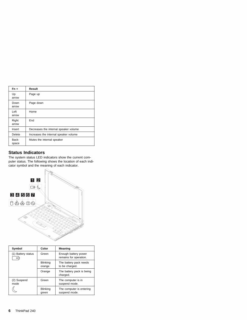
Status IndicatorsThe system status LED indicators show the current com-puter status. The following shows the location of each indi-cator symbol and the meaning of each indicator.
ThinkPad
Symbol Color Meaning
(1) Battery status Green Enough battery powerremains for operation.
Blinkingorange
The battery pack needsto be charged.
Orange The battery pack is beingcharged.
(2) Suspendmode
Green The computer is insuspend mode.
Blinkinggreen
The computer is enteringsuspend mode.
6 ThinkPad 240

Symbol Color Meaning
(3) Drive in use Orange Data is being read fromor written to the harddisk drive. Do not enterhibernation mode orpower off the computerwhen this indicator is on.
(4) Numeric lock Green The numeric keypad onthe keyboard is enabled.You enable or disablethe keypad by pressingand holding the Fn key,and pressing the NumLkkey. For details, see theUser's Reference.
(5) Caps lock Green Caps Lock mode isenabled. All alphabeticcharacters (A-Z) areentered in capital letterswithout the Shift keybeing pressed. Youenable or disable theCaps Lock mode bypressing and holding theFn key, and pressing theCaps Lock key.
(6) Scroll lock Green Scroll Lock mode isenabled. The Arrowkeys can be used asscreen-scroll functionkeys. The cursor cannotbe moved with theArrow keys. Not allapplication programssupport this function.You enable or disableScroll Lock mode bypressing and holding theFn key, and pressing theScrLk key.
(7) Power on Green The computer is opera-tional. This indicator isalways on when thecomputer is on and notin suspend mode.
Checkout GuideUse the following procedure as a guide for computer prob-lems.
Note: The diagnostic tests are intended to test only IBMproducts. Non-IBM products, prototype cards, ormodified options can give false errors and invalidsystem responses.
ThinkPad 240 7
1. Obtain the failing symptoms in as much detail as pos-sible.
2. Verify the symptoms by attempting to recreate thefailure by running the diagnostic test or by repeatingthe same operation.
Note: To run the diagnostics, refer to “Running theDiagnostics” on page 23
3. Use the following table with the verified symptom todetermine which page to go to. Search the symptomscolumn and find the description that best matchesyour symptom; then go to the page shown in the "Goto" column.
Symptoms (Verified) Go to
Power failure. (Thepower-on indicator does notgo on or stay on.)
“Power System Checkout”on page 10, then use tablein “Power-RelatedSymptoms” on page 20.
POST does not complete.No beeps or errorcodes/messages are indi-cated.
“Symptom-to-FRU Index” onpage 16, then use table in“No Beep Symptoms” onpage 19.
POST beeps, but no errorcodes are displayed.
“Symptom-to-FRU Index” onpage 16.
POST detected an error anddisplayed numeric errorcodes.
“Symptom-to-FRU Index” onpage 16, then use table in“Numeric Error Codes” onpage 16.
The diagnostic test detectedan error and displayed aFRU code.
“Running the Diagnostics”on page 23.
Other symptoms (such asLCD display problems).
“Symptom-to-FRU Index” onpage 16.
Symptoms cannot be recre-ated (intermittent problems).
Use the customer-reportedsymptoms, and go to“Symptom-to-FRU Index” onpage 16.
Audio CheckoutDo as follows:
1. Boot from the diagnostics diskette and start theprogram.
2. Go to Interactive Tests on the main menu and selectthe Internal Speaker test.
3. If no sound is heard, replace the speaker.
Fan ASM CheckoutTo check the fan ASM, do the following:
1. Boot from the diagnostics diskette and start theprogram.
8 ThinkPad 240

2. Go to Diagnostics on the main menu and selectOther Devices .
3. Follow the description in the window. If the testdetects a fan ASM problem, replace the fan.
Keyboard and Auxiliary Input DeviceCheckoutNote: Remove the external keyboard if the internal key-
board is to be tested.
If the internal keyboard does not work or an unexpectedcharacter appears, make sure that the flexible cableextending from the keyboard is correctly seated on theconnector.
If the keyboard cable connection is correct, run the Key-board Test. See “Running the Diagnostics” on page 23 fordetails.
If the test detects a keyboard problem, do the followingone at a time to correct the problem. Do not replace a non-defective FRU.
1. Replace the keyboard.
2. Replace the system board.
The following auxiliary input devices are supported for thiscomputer:
� Numeric keypad
� Mouse (PS/2 compatible)
� External keyboard (with keyboard/mouse cable)
If any of these devices do not work, reseat the cable con-nector and repeat the failing operation.
If the problem does not reoccur, replace the device andthen the system board.
Memory CheckoutDIMM are available for increasing memory capacity.
Onboard (MB) Slot (MB) Total Memory(MB)
32 0 32
32 32 64
32 64 96
32 128 160
64 0 64
64 32 96
64 64 128
64 128 192
ThinkPad 240 9

Memory errors might stop system operation, show errormessages on the screen, or hang the system.
Use the following procedure to isolate memory problems:
1. Turn off the computer and remove any installed DIMMfrom its slot.
2. Boot from the diagnostics diskette and start theprogram.
3. Go to Diagnostics on the main menu and selectMemory Test. If an error appears, replace the systemboard.
4. Turn off the computer and reinstall the DIMM; thenturn on the computer. Verify the memory size; thentest the memory. If an error appears, replace theDIMM.
Note: Make sure that the DIMM is properly installed intothe connector. A loose connection can cause anerror.
Modem Board CheckoutDo the following to isolate the problem to the systeminternal modem:
1. Boot from the diagnostics diskette and start theprogram.
2. Go to Diagnostics on the main menu and selectOther Devices .
3. Follow the description in the window.
4. If the test detects a modem problem, replace themodem card.
Power System CheckoutTo verify the symptom of the problem power on the com-puter using each of the following power sources:
1. Remove the battery ASM.
2. Connect the AC Adapter and check that power is sup-plied.
3. Disconnect the AC Adapter and install the chargedbattery ASM; then check that power is supplied by thebattery ASM.
If you suspect a power problem, refer to the appropriatepower supply check listed below:
� “Checking the AC Adapter” on page 11
� “Checking the Operational Charging” on page 11
� “Checking the Battery ASM” on page 11
10 ThinkPad 240

Checking the AC Adapter: You are herebecause the computer fails only when the AC Adapter isused:
� If the power-on indicator does not turn on, check thepower cord of the AC Adapter for correct continuityand installation.
� If the operational charge does not work, go to“Checking the Operational Charging.”
Unplug the AC Adapter cable from the computer andmeasure the output voltage at the plug of the AC Adaptercable. See the following figure.
If the voltage is not correct, replace the AC Adapter.
If the voltage is within the range, do the following:
� Replace the system board.
� If the problem is not corrected, go to “UndeterminedProblems” on page 22
Note: An audible noise from the AC Adapter does notalways indicate a defective adapter.
Checking the Operational Charging: Tocheck operational charging, use a discharged battery pack(battery ASM) or a battery ASM that has less than 50% ofthe total power remaining when installed in the computer.
Perform operational charging. If the battery status indicatordoes not turn on, remove the battery ASM and let it returnto room temperature. Reinstall the battery ASM.
If the charge indicator still does not turn on, replace thebattery ASM. If the charge indicator still does not turn on,replace the system board. Then reinstall the battery ASM.If the reinstalled battery ASM is not charged, go to the nextsection.
Checking the Battery ASM: Do the following:
1. Power off the computer.
2. Remove the battery ASM and measure the voltagebetween battery terminals 1(+) and 5(-). See the fol-lowing figure:
Pin Voltage (V dc)
1 +15.5 to +17.0
2 Ground
ThinkPad 240 11

Note: Signal lines, not used in these steps, are usedfor communications between the system andthe battery.
3. If the voltage is less than 10.6V, the battery ASM hasbeen discharged, recharge the battery ASM. If thevoltage is still less than 10.6V, replace the battery.
TrackPoint CheckoutIf the external mouse is connected, the TrackPoint doesnot work. In this case, please detach the external mouse tocheck the TrackPoint.
If this does not correct the TrackPoint problem, continuewith the following:
After you use the TrackPoint, the pointer drifts on thescreen for a short time. This self-acting pointer movementcan occur when a slight, steady pressure is applied to theTrackPoint pointer. This symptom is not a hardwareproblem. No service actions are necessary if the pointermovement stops in a short period of time.
If a click button problem or pointing stick problem occurs,do the following:
1. Boot from the diagnostics diskette and start theprogram.
2. Go to Interactive Tests on the main menu and selectMouse .
3. Follow the instructions in the message window.
If either the pointing stick or the click button does not work,do the following actions one at a time to correct theproblem. Do not replace a non-defective FRU.
1. Reseat the keyboard Touchbutton cables.
2. Replace the keyboard.
3. Replace the system board.
12 ThinkPad 240

I/O Ports CheckoutNote: Be sure to enable the serial and parallel ports in
the BIOS setup utility before performing diagnosticstests on the I/O ports.
Also, be sure to write down the I/O address for theserial port to identify the port in the diagnostic test.
Do perform a diagnostics checkout on the I/O ports:
1. Boot from the diagnostics diskette and start theprogram.
2. Go to Diagnostics on the main menu and selectSerial Ports or Parallel Ports .
Note: If you want to do a check on the infrared port,select Serial Ports .
3. In the Serial Port Test Category, you can check fouritems:
� Registers and Interrupts
� Internal Loopback
� External Loopback
� FIFO Buffers (16550A)
Move the cursor to the item you want to check, andpress Enter. Then follow the instructions on thescreen.
Note: To do an External Loopback test, you musthave a Loopback plug.
4. In the Parallel Port Test Category, you can check twoitems:
� Command And Data Port
� External Loopback And IRQ
Move the cursor to the item you want to check, andpress Enter. Then follow the instructions on thescreen.
Note: To do an External Loopback And IRQ test,you must have a Loopback plug.
Power Management FeaturesThree power management modes are available in the com-puter system to reduce power consumption and to prolongbattery life.
Standby Mode: In standby mode, the followingoccurs:
� The LCD backlight turns off.
� The hard disk drive motor stops.
Events that cause the computer to enter standby mode:
� Standby mode requested by the Fn key (Fn+F3).
ThinkPad 240 13

The computer exits standby and resumes operation whenany key is pressed.
Suspend Mode: In suspend mode, the followingoccurs:
� The LCD is powered off.
� The hard disk drive is powered off.
� The CPU stops.
Events that cause the computer to enter suspend mode:
� Suspend mode requested by the Fn key (Fn+F4).
� The Lid is closed.
� The specified time has elapsed.
� Battery low occurs and hibernation conditions areinsufficient.
Note: When battery is low, the battery status indi-cator blinks orange.
Note: In the IBM BIOS Setup Utility, the computer can beset to suspend when the lid is closed.
The following events cause the computer to resume opera-tion from suspend mode:
� The Lid is opened.
� The real time clock alarm is signaled.
� The ring indicator (RI) is signaled by a PC Carddevice or the internal modem.
� The Fn key is pressed.
� Power switch is pressed.
The computer also exits suspend mode when the battery iscritically low or timer conditions are satisfied for enteringhibernation mode.
Hibernation Mode: For Windows NT user:
A Windows NT user cannot create a hibernation file in aWindows NT system that uses the NTFS format system. Ifyou want to use hibernation mode, you should reinstallWindows NT with a FAT format system. Also, if bootmanager is installed, the computer cannot enterhibernation mode.
Note: Before using hibernation mode, you need ahibernation file.
In hibernation mode, the following occurs:
� The system status, RAM, VRAM, and setup data arestored on the hard disk.
� The system is powered off.
Events that cause the computer to enter hibernation mode:
� Hibernation mode requested by function key (Fn+F9).
14 ThinkPad 240

� Timer conditions are satisfied in suspend mode whenhibernate by timer is enabled.
� A critically low battery condition occurs.
� The power switch is pressed. (BIOS Setup)
The computer exits hibernation mode and resumes opera-tion when the power-on switch is pressed. When power isturned on, the hibernation file in the boot record on thehard disk drive is read and the system status is restoredfrom the hard disk drive.
The power switch must be pressed to cause the computerto resume operation from hibernation mode.
How to Create the Hibernation Function: Do asfollows:
� Turn off the computer.
� Insert the hibernation utility diskette into the diskettedrive (you can create the diskette using the DisketteFactory).
� Turn on the computer.
� Follow the instructions on the screen.
Note: If you change the memory size, you need torecreate the hibernation file or partition. Forpartition-based hibernation, use the hibernationutility to delete the partition first before creating anew one.
ThinkPad 240 15

Symptom-to-FRU IndexThe Symptom-to-FRU Index lists the symptoms and errorsand the possible causes. The most likely cause is listedfirst.
Note: Perform the FRU replacement or actions in thesequence shown in the FRU/Action columns. If aFRU replacement does not solve the problem, putthe original part back in the computer. Do notreplace a non-defective FRU.
This index can also be used to help you decide the nextpossible FRUs to be replaced when servicing a computer.
Numeric error codes show the errors detected in POST orsystem operation (runtime). In the following error codes, Xcan be any number. If no codes are available, use narra-tive symptoms.
If the symptom is not listed, go to “UndeterminedProblems” on page 22.
Note: For IBM devices not supported by diagnostic codesin this ThinkPad computer, see the manual for thatdevice.
Numeric Error CodesThe following is a list of the message that the BIOS candisplay. Most of them occur during POST. Some of themdisplay information about a hardware device, e.g., theamount of memory installed. Others may indicate aproblem with a device, such as the way it has been config-ured. Following the list are explanations of the messagesand remedies for reported problems.
If the system fails after you make changes in the Setupmenus, reset the computer, enter Setup and install Setupdefaults or correct the error.
Symptom/Error FRU/Action in Sequence
0200
Failure FixedDisk
1. Reseat hard disk drive.
2. Load Setup Defaults in BIOS SetupUtility.
3. Hard disk drive
4. System board
0211
Stuck Key
Go to “Keyboard and Auxiliary InputDevice Checkout” on page 9.
0211
Keyboarderror
Go to “Keyboard and Auxiliary InputDevice Checkout” on page 9.
0212
KeyboardControllerFailed
Go to “Keyboard and Auxiliary InputDevice Checkout” on page 9.
16 ThinkPad 240

Symptom/Error FRU/Action in Sequence
0213
Keyboardlocked —Unlock keyswitch
Unlock external keyboard.
0220
Monitor typedoes notmatch CMOS— Run Setup
Load Setup Defaults in BIOS Setup Utility.
0230
Shadow RAMFailed atoffset:nnnn
System board
0231
System RAMFailed atoffset:nnnn
1. DIMM
2. System board
0232
ExtendedRAM Failedat offset:nnnn
1. DIMM
2. System board
0250
Systembattery isdead
System board
0251
SystemCMOSchecksumbad —Default con-figurationused
System board
0260
System timererror
1. Run BIOS Setup Utility to reconfigurethe system, then reboot the system.
2. System board
0270
Real timeclock error
1. Run BIOS Setup Utility to reconfigurethe system, then reboot the system.
2. System board
0280
Previous bootincomplete —Default con-figurationused
1. Load Setup Defaults in the BIOSSetup Utility.
2. System board
ThinkPad 240 17

Symptom/Error FRU/Action in Sequence
0281
Memory sizefound byPOST dif-fered fromCMOS
1. Load Setup Defaults in the BIOSSetup Utility.
2. DIMM
3. System board
02D0
Systemcache error— Cache dis-abled
System board
02F0
CPU ID:
System board
02F5
DMA TestFailed
1. DIMM
2. System board
02F6
Software NMIFailed
1. DIMM
2. System board
02F7
Fail-SafeTimer NMIFailed
1. DIMM
2. System board
Error MessagesSymptom/Error FRU/Action in Sequence
DeviceAddress Con-flict
1. Load Setup Defaults in BIOS SetupUtility.
2. System board
AllocationError for:device
1. Load Setup Defaults in BIOS SetupUtility.
2. System board
Failing Bits:nnnn
1. DIMM
2. System board
InvalidSystem Con-figurationData
System board
I/O deviceIRQ conflict
1. Load Setup Defaults in BIOS SetupUtility.
2. System board
Operatingsystem notfound
1. Enter BIOS Setup Utility and see ifthe hard disk drive and diskette driveA: are properly identified.
2. Hard disk drive
3. System board
18 ThinkPad 240

No Beep SymptomsSymptom/Error FRU/Action in Sequence
No beep, power-onindicator on, LCDblank, no POST
� Ensure every connector isconnected tightly and cor-rectly.
� DIMM
� System board
No beep, power-onindicator off, LCDblank during POST
� Battery ASM
� AC Adapter
� System board
No beep, power-onindicator on, LCDblank during POST
� Reseat DIMM.
� System board
No beep duringPOST but systemruns correctly.
Speaker
LCD-Related SymptomsSymptom/Error FRU/Action in Sequence
LCD backlight notworking
LCD too dark
LCD brightnesscannot be adjusted
LCD contrast cannotbe adjusted
1. Reseat the LCD connector.
2. LCD FPC ASM
3. LCD inverter
4. LCD
5. System board
LCD screen unread-able
Character missingpels
Screen abnormal
Wrong color dis-played
1. Reseat the LCD connector.
2. LCD FPC ASM
3. LCD inverter
4. LCD
5. System board
LCD has extra hori-zontal or vertical linesdisplayed.
1. LCD FPC ASM
2. LCD inverter
3. LCD
4. System board
Keyboard-Related SymptomsSymptom/Error FRU/Action in Sequence
Keyboard (one ormore keys) doesn'twork.
1. Reseat the keyboard cable.
2. Keyboard
3. System board
Indicator-Related Symptoms
ThinkPad 240 19

Symptom/Error FRU/Action in Sequence
Indicator incorrectlyremains off or on, butsystem runs cor-rectly.
1. Reseat the LED cable.
2. LED cable
3. System board
Power-Related SymptomsSymptom/Error FRU/Action in Sequence
Power shuts downduring operation.
1. Battery
2. AC Adapter
3. System board
The system will notpower on.
1. Battery ASM
2. AC Adapter
3. System board
The system will notpower off.
1. System board
Battery can't becharged.
� Battery
� System board
PC Card (PCMCIA)-Related SymptomsSymptom/Error FRU/Action in Sequence
System cannot detectthe PC Card(PCMCIA)
1. PC Card (PCMCIA) slotsassembly
2. System board
Speaker-Related SymptomsSymptom/Error FRU/Action in Sequence
Speakers make noiseor no sound comesfrom system.
1. Speaker
2. System board
In DOS or Windowsmultimedia programs,no sound comes fromthe computer.
1. Speaker
2. System board
Power Management-Related SymptomsSymptom/Error FRU/Action in Sequence
The system will notenter hibernationmode.
1. Keyboard (if control is fromthe keyboard)
2. Hard disk drive
3. System board
The system will notwake up fromhibernation mode.
1. Keyboard (if control is fromthe keyboard)
2. Hard disk drive
3. System board
20 ThinkPad 240

Symptom/Error FRU/Action in Sequence
The system will notenter suspend modeafter closing the LCD.
1. LED Card ASM (R)
2. System board
Battery fuel-gaugedoes not go higherthan 90%.
1. Remove battery ASM and letit cool for 2 hours.
2. Refresh battery (continueusing battery in BIOS Setupmode until power off, thencharge battery).
3. Battery
4. System board
System configurationdoes not match theinstalled devices.
1. Load Setup Defaults andreboot the system.
System hangsintermittently.
1. Fan ASM
2. System board
Peripheral-Device-Related Symptom
Note: If you cannot find a symptom or an error in this listand the problem remains, see “UndeterminedProblems” on page 22.
Symptom/Error FRU/Action in Sequence
External display doesnot work correctly.
System board
USB does not workcorrectly.
System board
Print problems � Run printer self-test.
� Printer driver
� Printer cable
� System board
Serial or parallel portdevice problems
� Device driver
� Device cable
� Device
� System board
Intermittent ProblemsIntermittent system hang problems can be caused by avariety of reasons that have nothing to do with a hardwaredefect, such as cosmic radiation, electronic discharge, orsoftware errors. FRU replacement should be consideredonly when a recurring problem exists.
When analyzing an intermittent problem, do the following:
1. Run the diagnostic test for the system board in loopmode at least 10 times.
2. If no error is detected, do not replace any FRUs.
ThinkPad 240 21

3. If any error is detected, replace the FRU shown bythe FRU code. Rerun the test to verify that no moreerrors exist.
Undetermined ProblemsYou are here because the diagnostic tests did not identifywhich adapter or device failed, which installed devices areincorrect, whether a short circuit is suspected, or whetherthe system is inoperative. Follow these procedures toisolate the failing FRU (do not isolate non-defective FRUs).
Verify that the power supply being used at the time of thefailure is operating correctly. (See “Power SystemCheckout” on page 10.)
1. Power off the computer.
2. Visually check for damage. If any problems are found,replace the FRU.
3. Remove or disconnect all of the following devices:
a. Non-IBM devices
b. Printer, mouse, and other external devices
c. Battery ASM
d. Hard disk drive
e. DIMM
f. PC Cards (PCMCIA)
4. Power on the computer.
5. Determine if the problem has changed.
6. If the problem does not recur, reconnect the removeddevices one at a time until you find the failing FRU.
7. If the problem remains, replace the following FRUsone at a time. Do not replace a non-defective FRU.
a. System board
b. LCD panel ASM
22 ThinkPad 240

CE Utility Program Diskette
Writing the VPD DataThe EEPROM on the system board contains the VitalProduct Data (VPD) — that is, a computer serial numberand a system board serial number. When you replace thesystem board, restore the computer serial number usingthe VPD Data Utility in the ThinkPad CE Utility Diskette.The serial number label is attached to the computer.
Flash UUIDThe EEPROM on the system board contains the UniversalUnique ID (UUID) — that is, for Microsoft or Internet use.When you replace the system board using the Flash UUIDUtility in the ThinkPad CE Utility Diskette. The UUID utilitywill automatically assign the UUID via Windows.
Running the DiagnosticsUse either the TrackPoint or the cursor move keys tointeract with the tests.
1. Connect the external floppy disk drive to the com-puter.
2. Insert the PC Doctor startup disk into the diskettedrive.
3. Power-on the computer.
4. From the PC DOS 7.0 Startup Menu, select 1.ThinkPad 240 and press Enter.
The PC-Doctor diagnostic program will load.
5. At the main menu, select the test to run.
6. Press Enter to run the test selected.
7. After starting a test, do not press any key untilprompted, then follow the instructions on the screen.
8. When the test is completed, press Esc to return tothe main menu.
9. Select Quit/Exit Diags to exit the diagnostics utility.
ThinkPad 240 23
FRU Removals and ReplacementsThis section contains information about removals andreplacements.
� Do not damage any parts. Only certified and trainedpersonnel should service the computer.
� The arrows in this section show the direction of move-ment to remove a FRU, or to turn a screw to releasethe FRU. The arrows are marked in numeric order, insquare callouts, to show the correct sequence ofremoval.
� When other FRUs must be removed before the failingFRU is removed, they are listed at the top of thepage.
� To replace a FRU, reverse the removal procedureand follow any notes that pertain to replacement.
� When replacing a FRU, use the correct screw size, asshown in the procedures.
Safety Notice 1:
Before the computer is powered on after FRU replace-ment, make sure all screws, springs, or other small parts,are in place and are not left loose inside the computer.Verify this by shaking the computer and listening for rat-tling sounds. Metallic parts or metal flakes can cause anelectrical short circuit.
Safety Notice 4:
The battery can cause a fire, explosion, or severe burn. Donot recharge it, remove its polarized connector, disas-semble it, heat it above 100°C (212 °F), incinerate it, orexpose its cell contents to water. Dispose of the battery asrequired by local ordinances or regulations. Use only thebattery in the appropriate parts listing. Use of an incorrectbattery can result in ignition or explosion of the battery.
Safety Notice 8:
Before removing any FRU, power-off the computer, unplugall power cords from electrical outlets, remove the batteryASM, and then disconnect any interconnecting cables.
An electrostatic discharge (ESD) strap (P/N 6405959) mustbe used to establish personal grounding.
FRU Service ProceduresReview the following procedures before replacing anyFRU.
24 ThinkPad 240

LCD FRU Replacement Notice: The TFT LCDfor the notebook computer contains over 2,359,296 thin-film transistors (TFTs). A small number of missing, discol-ored, or lighted dots (on all the time) is characteristic ofTFT LCD technology, but excessive pixel problems cancause viewing concerns. The LCD should be replaced ifthe number of missing, discolored, or lighted dots in anybackground is 8 or more.
Replacing the System Board: When youreplace the system board, restore the computer serialnumber using the VPD Data Utility and reassign the UUIDusing the Flash UUID Utility in the ThinkPad 240 ThinkPadHardware Maintenance Diskette.
Note: Do not power off the computer while restoring theVPD.
Important Notice
This computer uses special nylon-coated screws withthe following characteristics:
� They maintain tight connections.
� They do not easily come loose, even with shockor vibration.
� They need additional force to tighten.
� They should be used only once.
Do the following when you service this computer:
� Have a screw kit (10L1956) available.
� Always use new screws if you are instructed.
� Use a torque screwdriver if you have one.
ThinkPad 240 25

1010 Battery ASMTo remove the battery ASM:
1. Slide the release lock as shown.
2
1
2
1
2. Slide the release latch as shown.
3. Remove the battery ASM.
Reverse the steps described above when installing a newbattery pack.
26 ThinkPad 240

1020 Hard Disk DriveWarning
� Do not drop or apply any shock to the hard disk drive.The hard disk drive is sensitive to physical shock.Incorrect handling can cause damage and permanentloss of data on the drive.
� Before removing the drive, have the user make abackup copy of all the information on the drive if pos-sible.
� Never remove the drive while the system is operatingor is in suspend mode.
To remove the hard disk drive:
1. Remove the two screws from the hard disk cover.
2. Slide the hard disk drive module as shown.
3. Lift as shown to remove the hard disk drive module.
StepSize (Quan-tity)
Head &Color Torque
1 M2.5 x 7L (2) Flat head,black
2.5 kgf-cm
Note: Make sure you use the correct screw for replacement.
ThinkPad 240 27

1030 Keyboard� 1010 Battery ASM
To remove the keyboard:
1. Remove the three screws securing the keyboard.
2. Turn the notebook over; then lift the keyboard asshown.
Thi
nkP
adThi
nkP
ad
3. Remove the keyboard stopper sheet screw.
4. Disconnect the keyboard connector from the systemboard. Remove the keyboard from the lower case.
28 ThinkPad 240

Thi
nkP
adThi
nkP
ad
StepSize (Quan-tity)
Head &Color Torque
1 M2.0 x 9L (3) Flat head,black
2.5 kgf-cm
3 M2.5 x 6L (1) Flat head,silver
2.5 kgf-cm
Note: Make sure you use the correct screw for replacement.
ThinkPad 240 29

1040 Modem Card� 1010 Battery ASM
� 1030 Keyboard
To remove the modem card:
1. Carefully release the latches on both sides of themodem card.
Thi
nkP
adThi
nkP
ad
2. Disconnect the modem cable from the connector.
3. Gently remove the modem card.
30 ThinkPad 240

1050 DIMM Card� 1010 Battery ASM
� 1030 Keyboard
To remove the memory card:
1. Carefully release the latches on both sides of thememory card.
Thi
nkP
adThi
nkP
ad
2. Gently remove the memory card.
ThinkPad 240 31

1060 LCD Unit ASMNote: Refer to “ThinkPad 240 Hardware Maintenance
Manual” on page 1 for information on LCD Type Aand LCD Type B panel designations.
� 1010 Battery ASM
� 1030 Keyboard
Note: The Cu tape must be reseated firmly after the LCDunit ASM is replaced .3/.
To remove the LCD unit ASM:
1. Remove the screws as shown.
2
1
2. Turn the notebook over; then remove the hingecovers.
3. Remove the Cu tape from the FPC cable.
4. Disconnect the LCD FPC cable from the systemboard.
5. Remove the LCD hinge screws.
6. Raise the upper cover enough to remove the FPCcable. Remove the LCD unit.
32 ThinkPad 240

StepSize (Quan-tity)
Head &Color Torque
1 M2.0 x 4L (2) Flat head,black
2.5 kgf–cm
5 M2.5 x 6 L(4)
Flat head,silver
3.5 kgf-cm
Note: Make sure you use the correct screw for replacement.
ThinkPad 240 33

1070 Upper Cover ASM� 1010 Battery ASM
� 1020 Hard Disk Drive
� 1030 Keyboard
� 1060 LCD Unit ASM
To remove the upper cover ASM:
1. Remove the screw cover.
2. Remove the screw.
3. Remove the other screw as shown.
4. Turn the notebook over; then remove the two screws.
StepSize (Quan-tity)
Head &Color Torque
2 M2.0 x 4L (1) Flat head,black
2.5 kgf-cm
3 M2.5 x 7L (1) Flat head,black
2.5 kgf-cm
4 M2.0 x 4L Flat head,black
2.0 kgf-cm
Note: Make sure you use the correct screw for replacement.
34 ThinkPad 240
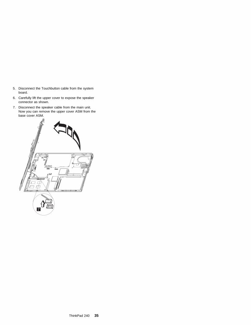
5. Disconnect the Touchbutton cable from the systemboard.
6. Carefully lift the upper cover to expose the speakerconnector as shown.
7. Disconnect the speaker cable from the main unit.Now you can remove the upper cover ASM from thebase cover ASM.
ThinkPad 240 35

1080 Speaker ASM� 1010 Battery ASM
� 1020 Hard Disk Drive
� 1030 Keyboard
� 1060 LCD Unit ASM
� 1070 Upper Cover ASM
To remove the speaker:
1. Remove the three screws securing the speaker.
2. Remove the securing tape from the cable.
3. Gently lift the speaker away from the upper cover.
StepSize (Quan-tity)
Head &Color Torque
1 M2.0 x 3L (3) Flat head,silver
2.5 kgf-cm
Note: Make sure you use the correct screw for replacement.
36 ThinkPad 240

1085 Select Button ASM� 1010 Battery ASM
� 1020 Hard Disk Drive
� 1030 Keyboard
� 1060 LCD Unit ASM
� 1070 Upper Cover ASM
To remove the select button ASM:
1. Remove the three screws as shown.
2. Remove the select button ASM from the top coverASM.
StepSize (Quan-tity)
Head &Color Torque
1 M2.5 x 2.5L(3)
Flat head,silver
2.0 kgf-cm
Note: Make sure you use the correct screw for replacement.
ThinkPad 240 37

1090 Cable ASM and Cable ASM LED-R� 1010 Battery ASM
� 1020 Hard Disk Drive
� 1030 Keyboard
� 1060 LCD Unit ASM
� 1070 Upper Cover ASM
To remove the hinge LED cable:
1. Disconnect the LED cable, then lift it as shown. (Thecable is fixed with double-sided tape.)
To remove the cable ASM LED-R:
1. Remove the screw.
2. Disconnect the LED board, then lift it as shown.
StepSize (Quan-tity)
Head &Color Torque
1 M2.0 x 7L (1) Flat head,silver
2.0 kgf-cm
Note: Make sure you use the correct screw for replacement.
38 ThinkPad 240

1100 Fan ASM� 1010 Battery ASM
� 1020 Hard Disk Drive
� 1030 Keyboard
� 1060 LCD Unit ASM
� 1070 Upper Cover ASM
� 1090 Cable ASM and Cable ASM LED-R
Warning
Do not apply pressure on the fan blades or hub assembly;doing so can damage the fan bearings.
To remove the fan ASM:
1. Remove the two screws securing the fan ASM.
2. Carefully lift the fan ASM.
3. Disconnect the cable from the system board.
Warning
When reassembling the fan, ensure that you insert thescrews in the order shown in the following illustration:
StepSize (Quan-tity)
Head &Color Torque
1 M2.0 x 7L (2) Flat head,silver
2.0 kgf-cm
ThinkPad 240 39

StepSize (Quan-tity)
Head &Color Torque
Note: Make sure you use the correct screw for replacement.
40 ThinkPad 240

1110 Modem Cable ASM� 1010 Battery ASM
� 1020 Hard Disk Drive
� 1030 Keyboard
� 1060 LCD Unit ASM
� 1070 Upper Cover ASM
To remove the modem cable ASM:
� Disconnect the modem cable from the system board.Remove the cable as shown.
ThinkPad 240 41
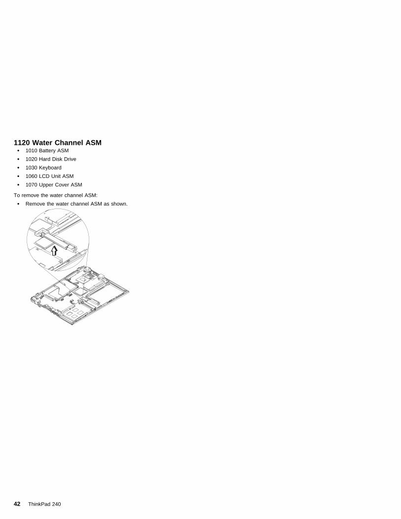
1120 Water Channel ASM� 1010 Battery ASM
� 1020 Hard Disk Drive
� 1030 Keyboard
� 1060 LCD Unit ASM
� 1070 Upper Cover ASM
To remove the water channel ASM:
� Remove the water channel ASM as shown.
42 ThinkPad 240

1130 System Board� 1010 Battery ASM
� 1020 Hard Disk Drive
� 1030 Keyboard
� 1060 LCD Unit ASM
� 1070 Upper Cover ASM
� 1090 Cable ASM and Cable ASM LED-R
� 1100 Fan ASM
� 1120 Water Channel ASM
Note: See “Replacing the System Board” on page 25before proceeding.
1. Remove the screws as shown.
2. Turn the notebook over; remove the two screws fromthe diskette drive connector.
3. Remove the screw from the PCMCIA slot.
4. Remove the battery terminal screw.
5. Gripping firmly as shown, separate the base coveraround the sides from the system board.
ThinkPad 240 43

6. Remove the system board from the base cover ASM.
StepSize (Quan-tity)
Head &Color Torque
1 M2.0 x 4L (5) Flat head,black
2.5 kgf-cm
2 M2.0 x 6L (2) Flat head,black
2.0 kgf-cm
3 M2.0 x 4L (1) Flat head,black
2.0 kgf-cm
4 M2.0 x 8L (1) Flat head,black
2.0 kgf-cm
Note: Make sure you use the correct screw for replacement.
44 ThinkPad 240

1135 Rear Bracket� 1010 Battery ASM
� 1020 Hard Disk Drive
� 1030 Keyboard
� 1060 LCD Unit ASM
� 1070 Upper Cover ASM
� 1090 Cable ASM and Cable ASM LED-R
� 1100 Fan ASM
� 1120 Water Channel ASM
� 1130 System Board
Note: See “Replacing the System Board” on page 25before proceeding.
1. Remove the six hexagonal studs as shown.
2. Remove the microphone.
3. Remove the rear bracket.
StepSize (Quan-tity)
Head &Color Torque
1 M2.5 x 4.5L(6)
Hex head,silver
4.0 kgf-cm
Note: Make sure you use the correct screw for replacement.
ThinkPad 240 45

1140 PCMCIA Slots� 1010 Battery ASM
� 1020 Hard Disk Drive
� 1030 Keyboard
� 1060 LCD Unit ASM
� 1070 Upper Cover ASM
� 1090 Cable ASM and Cable ASM LED-R
� 1100 Fan ASM
� 1120 Water Channel ASM
� 1130 System Board
Warning
Special care must be taken when disconnecting thePCMCIA card not to cause a short or damage the con-nector.
To remove the PCMCIA slots:
1. Remove the screw securing the PCMCIA slot board.
2. Use a flat-bladed screwdriver to disconnect thePCMCIA card from the connector.
3. Carefully remove the PCMCIA card.
StepSize (Quan-tity)
Head &Color Torque
1 M2.0 x 7L (1) Flat head,silver
2.0 kgf-cm
Note: Make sure you use the correct screw for replacement.
46 ThinkPad 240

1150 LCD Bezel ASM� 1010 Battery ASM
1. Remove the screw cap covers.
2. Remove the screws as shown.
Thi
nkP
adThi
nkP
ad
A
3. Gripping as shown, remove the LCD bezel.
4. The LCD latches must be opened as shown toremove the bezel.
Thi
nkP
adThi
nkP
ad
5. Remove the bezel from the LCD unit.
StepSize (Quan-tity)
Head &Color Torque
2 M2.5 x 5L (2) Flat head,black
2.5 kgf-cm
2A M2.5 x 5L (2) Flat head,black
1.5 kgf-cm
Note: Make sure you use the correct screw for replacement.
ThinkPad 240 47

1160 LCD Inverter ASM� 1010 Battery ASM
� 1150 LCD Bezel ASM
To remove the LCD inverter ASM:
1. Disconnect the flex cable from the inverter card.
2. Disconnect the FPC cable from the inverter card.
Thi
nkP
ad
3. Remove the inverter card. (The inverter card is fixedto the rear cover with double-sided tape.)
48 ThinkPad 240

1170 LCD Panel ASM (LCD Type A andB)Note: Refer to “ThinkPad 240 Hardware Maintenance
Manual” on page 1 for information on LCD Type Aand LCD Type B panel designations.
� 1010 Battery ASM
� 1030 Keyboard
� 1150 LCD Bezel ASM
� 1160 LCD Inverter ASM
To remove the LCD Panel:
1. Remove the screws as shown.
2
1
2. Turn the notebook over; remove the CU tape and dis-connect the FPC cable.
3. Remove the four screws securing the LCD Panel.
Thi
nkP
ad
4. Lift the top cover enough to pass the FPC connectorthrough.
ThinkPad 240 49
5. Remove the LCD panel.
StepSize (Quan-tity)
Head &Color Torque
1 M2.0 x 4L (2) Flat head,black
2.5 kgf–cm
3(LCDTypeA)
M2.5 x 4L (4) Flat head,silver
3.0 kgf–cm
3(LCDTypeB)
M2.0 x 4L (4) Flat head,silver
3.0 kgf–cm
Note: Make sure you use the correct screw for replacement.
50 ThinkPad 240

1180 LCD FPC ASM (LCD Type A)Note: Refer to “ThinkPad 240 Hardware Maintenance
Manual” on page 1 for information on LCD Type Aand LCD Type B panel designations.
� 1010 Battery ASM
� 1030 Keyboard
� 1150 LCD Bezel ASM
� 1160 LCD Inverter ASM
� 1170 LCD Panel ASM (LCD Type A and B)
Note: When replacing the flex cable in the following pro-cedure, the labelled face of the cable must faceaway from the LCD panel.
1. Remove the tape from the FPC cable.
2. Disconnect the FPC connector from the LCD panel.
Bs1 FPC 1A P/N DEPC1222AA
Career B through Bs1 FPC 1A P/N DEPC1222AA
3. Disconnect the flex cable from the LCD panel.
ThinkPad 240 51

1185 LCD FPC ASM (LCD Type B)Note: Refer to “ThinkPad 240 Hardware Maintenance
Manual” on page 1 for information on LCD Type Aand LCD Type B panel designations.
� 1010 Battery ASM
� 1030 Keyboard
� 1150 LCD Bezel ASM
� 1160 LCD Inverter ASM
� 1170 LCD Panel ASM (LCD Type A and B)
1. Remove the tape from the FPC cable.
2. Open the fasteners on the FPC cable holder.
3. Disconnect the FPC connector from the LCD panel.
52 ThinkPad 240

1190 Hinge ASM� 1010 Battery ASM
� 1030 Keyboard
� 1060 LCD Unit ASM
� 1150 LCD Bezel ASM
1. Remove the screws as shown.
2. Remove the hinge ASM.
StepSize (Quan-tity)
Head &Color Torque
1 M2.5 x 4L (2) Flat head,silver
3.5 kgf–cm
Note: Make sure you use the correct screw for replacement.
ThinkPad 240 53

Computer Parts Listing
a
b
c
d
Index Description FRUNumber
a —d
See MISC PARTS list 10L1955
1 HINGE CAP L/R 10L1954
2 UPPER COVER ASM 10L1944
3 REAR BRACKET 10L1952
4 LED CARD ASM (L) 10L1303
5 SERIAL/VGA CAP 10L1951
6 STD BATTERY PACK 02K6606
7 PCMCIA SLOT 10L1945
8 DISKETTE DRIVE CONNECTORLID
10L1953
9 TRACKPOINT CAP 84G6536
10 See Keyboard list
11 SELECT BUTTON ASM 10L1958
54 ThinkPad 240

Index Description FRUNumber
12 FAN ASM 10L1957
13 SPEAKER ASM 02K6307
14 LED CARD ASM (R) 10L1304
15 SYSTEM BOARD ASM 32 MB(Model 1)
10L1302
15 SYSTEM BOARD ASM 64 MB(Model 2)
30L2766
15 SYSTEM BOARD ASM 64 MB(Model 3)
08K3426
15 SYSTEM BOARD ASM 64 MB(Model 4)
08K3143
16 MODEM CARD ASM 10L1305
17 BASE COVER ASM 10L1946
BASE COVER ASM PRC 10L1948
BASE COVER ASM Korea 10L1949
18 HARD DISK DRIVE ASM 3.2 GB(Model 1)
05K9117
HARD DISK DRIVE ASM 6.4 GB(Model 2)
05K9119
HARD DISK DRIVE DOOR 10L1950
Description FRUNumber
AC ADAPTER
AC Adapter 56W (2 PIN) 02K6554
AC Adapter 56W (2 PIN) 02K6548
AC Adapter 56W (3 PIN) 02K6555
AC Adapter 56W (3 PIN) 02K6550
KEYBOARD
KBD ASM US English 02K6302
KBD ASM Japanese 02K6303
KBD ASM Traditional Chinese 02K6304
KBD ASM Korean 02K6305
KBD ASM Canadian French 02K6306
KBD ASM UK English 02K4938
KBD ASM German 02K4939
KBD ASM French 02K4940
Miscellaneous
Screw Kit 10L1956
MODEM CABLE ASM INTERNAL 05K2860
TELEPHONE CABLE US 27L0478
TELEPHONE CABLE Australia 27L0479
ThinkPad 240 55

Description FRUNumber
TELEPHONE CABLE UK 27L0480
TELEPHONE CABLE Germany 27L0481
TELEPHONE CABLE France 27L0482
32 MB DIMM 42H2819
64 MB DIMM 10L1313
128 MB DIMM 01K1153
EXTERNAL DISKETTE DRIVE CABLE 12J1711
EXTERNAL DISKETTE DRIVE ASM 05K898905K8990
LARGE BATTERY 02K6607
MISC PARTS
(a) MODEM DOOR
(b) SHUTTER (PCMCIA)
(c) SPRING SHUTTER
(d) WATER CHANNEL
(e) FPC HOLDER (upper)
(f) FPC HOLDER (lower)
(g) HOOK KNOB - R
(h) SPRING HOOK - R
(i) HOOK KNOB - L
(j) SPRING-HOOK - L
10L1955
Others
Power cord (Japan 2 PIN) 13H5273
Power cord (Argentina, Australia, Papua NewGuinea, New Zealand, Paraguay, Uruguay)
76H3514
Power cord (Bahamas, Barbados, Bermuda,Bolivia, Canada, Cayman Islands, Colombia,Costa Rica, Dominican Republic, Ecuador, ElSalvador, Guatemala, Guyana, Haiti,Honduras,Jamaica, Korea (South), Mexico,Netherlands, Antilles, Nicaragua, Panama,Peru, Philippines, Saudi Arabia, Suriname,Taiwan, Trinidad (West Indies), U.S.A.,Venezuela)
76H3516
Power cord (Austria, Belgium, Bulgaria,Czech Republic, Egypt, Finland, France,Germany, Greece, Hungary, Iceland,Indonesia, Netherlands, Norway, Poland,Portugal, Romania, Slovakia, Spain, Sweden,Turkey, former Yugoslavia)
76H3518
Power cord (Denmark) 76H3520
Power cord (Bangladesh, Pakistan, SouthAfrica, Sri Lanka)
76H3522
56 ThinkPad 240
Description FRUNumber
Power cord (Abu Dhabi, Albania, Antigua,Bahrain, Brunei, Dubai, Fiji, Hong Kong,India, Ireland, Kenya, Kuwait, Macao,Malaysia, Nigeria, Oman, People's Republicof China, Qatar, Singapore, United Kingdom)
76H3524
Power cord (Switzerland) 76H3528
Power cord (Israel) 76H3532
Power cord (Chile, Italy) 76H3530
Power cord (Korea) 76H3535
Power cord (PRC) 02K0539
ThinkPad 240 57

LCD Unit Parts Listing (LCD Type A)
e
fg
h
i
j
Note: Refer to “ThinkPad 240 Hardware MaintenanceManual” on page 1 for information on LCD Type Aand LCD Type B panel designations.
Index Computer FRUNumber
e — j See MISC PARTS list 10L1955
1 LCD BEZEL ASM 10L1941
LCD BEZEL ASM Korea 10L1942
2 LCD UNIT-TFT 10.4-inch 05K9523
3 LCD CABLE ASM 05K2859
4 HINGE ASM L/R 10L1943
5 LCD REAR COVER ASM 10L1939
LCD REAR COVER ASM Korea 10L1940
LCD REAR COVER ASM Korea(Hitachi panel)
08K5925
6 INVERTER CARD ASM 10L1306
58 ThinkPad 240

LCD Unit Parts Listing (LCD Type B)
e
fg
h
i
j
Note: Refer to “ThinkPad 240 Hardware MaintenanceManual” on page 1 for information on LCD Type Aand LCD Type B panel designations.
Index Computer FRUNumber
e — j See MISC PARTS list 10L1955
1 LCD BEZEL ASM 10L1941
LCD BEZEL ASM Korea 10L1942
2 LCD UNIT-TFT 10.4-inch 05K9589
3 LCD CABLE ASM 27L0489
4 HINGE ASM L/R 10L1943
5 LCD REAR COVER ASM 08K5820
LCD REAR COVER ASM Korea 10L1940
LCD REAR COVER ASM Korea(Hitachi panel)
08K5925
6 INVERTER CARD ASM 10L1431
Service Tools
Description FRU No.
Diagnostic Diskette N/A
CE Utility Diskette N/A
ThinkPad 240 59

Description FRU No.
Tri-Connector Wrap Plug 72X8546
PC Test Card 35G4703
Audio Wrap Cable 66G5180
Screwdriver Kit 95F3598
USB Parallel Test Cable 05K2580
Torque Screwdriver 05K4695
5 mm Socket Wrench 05K4694
Screwdriver 27L8126
60 ThinkPad 240

NoticesReferences in this publication to IBM products, programs,or services do not imply that IBM intends to make theseavailable in all countries in which IBM operates. Any refer-ence to an IBM product, program, or service is notintended to state or imply that only IBM product, program,or service may be used. Subject to IBM's valid intellectualproperty or other legally protectable rights, any functionallyequivalent product program, or service may be usedinstead of the IBM product, program, or service. The evalu-ation and verification of operation in conjunction with otherproducts, except those expressly designated by IBM, arethe responsibility of the user.
IBM may have patents or pending patent applications cov-ering subject matter in this document. The furnishing ofthis document does not give you any license to thesepatents. You can send license inquiries, in writing, to:
IBM Director of LicensingIBM Corporation500 Columbus AvenueThornwood, NY 10594U.S.A.
TrademarksThe following terms are trademarks or service marks ofIBM Corporation in the United States and other countries:
IBMPS/2ThinkPadTrackPointTrackPoint IV
The following terms are trademarks or service marks ofother companies as follows:
Intel Intel CorporationMylar E.I. Du Pont de Nemours and CompanyPCMCIA Personal Computer Memory Card Interface
AssociationPentium Intel Corporation
ThinkPad 240 61
IBM
Part Number: 09N8590
Printed in U.S.A.
S09N-8590-ðð


![IBM - CertKill · s@lm@n IBM Exam C8010-240 IBM Sterling Configurator V9.1, Deployment Version: 6.0 [ Total Questions: 112 ]](https://img.dokumen.tips/doc/110x75/5acb756f7f8b9a27628b53b5/ibm-certkill-lmn-ibm-exam-c8010-240-ibm-sterling-configurator-v91-deployment.jpg)