Embed Size (px)
DESCRIPTION
N3700 Hardware and Service Guide
Citation preview

IBM System Storage N series
N3700 Hardware and Service Guide
GA32-0515-03
���


IBM System Storage N series
N3700 Hardware and Service Guide
GA32-0515-03
���

Note:
Before using this information and the product it supports, be sure to read the general information in “Notices” on page 65.
Fourth Edition (September 2006)
© Copyright International Business Machines Corporation 2005, 2006. All rights reserved.
US Government Users Restricted Rights – Use, duplication or disclosure restricted by GSA ADP Schedule Contract
with IBM Corp.

Safety and environmental notices
This section contains information about:
v “Safety notices and labels”
v “Laser safety” on page vi
v “Rack safety” on page vii
v “Product recycling and disposal” on page viii
v “Battery return program” on page ix
v “Cable warning” on page x
Safety notices and labels
When using this product, observe the danger, caution, and attention notices
contained in this guide. The notices are accompanied by symbols that represent the
severity of the safety condition.
The following sections define each type of safety notice and provide examples.
The following notices and statements are used in IBM® documents. They are listed
below in order of increasing severity of potential hazards. Follow the links for more
detailed descriptions and examples of the danger, caution, and attention notices in
the sections that follow.
v Note: These notices provide important tips, guidance, or advice.
v “Attention notices” on page v: These notices indicate potential damage to
programs, devices, or data.
v “Caution notices” on page v: These statements indicate situations that can be
potentially hazardous to you.
v “Danger notices”: These statements indicate situations that can be potentially
lethal or extremely hazardous to you. Safety labels are also attached directly to
products to warn of these situations.
v In addition to these notices, “Labels” on page iv may be attached to the product
to warn of potential hazards.
Danger notices
A danger notice calls attention to a situation that is potentially lethal or extremely
hazardous to people. A lightning bolt symbol accompanies a danger notice to
represent a dangerous electrical condition. A sample danger notice follows.
DANGER
An electrical outlet that is not correctly wired could place
hazardous voltage on metal parts of the system or the devices
that attach to the system. It is the responsibility of the customer
to ensure that the outlet is correctly wired and grounded to
prevent an electrical shock.
A comprehensive danger notice provides instructions on how to avoid shock
hazards when servicing equipment. Unless instructed otherwise, follow the
procedures in the following danger notice.
© Copyright IBM Corp. 2005, 2006 iii

DANGER
Electrical voltage and current from power, telephone, and
communication cables are hazardous.
To avoid a shock hazard:
v Do not connect or disconnect any cables or perform
installation, maintenance, or reconfiguration of this product
during an electrical storm.
v Connect all power cords to a properly wired and grounded
electrical outlet. Ensure outlet supplies proper voltage and
phase rotation according to the system rating plate.
v Connect any equipment that will be attached to this product to
properly wired outlets.
v When possible, use one hand only to connect or disconnect
signal cables.
v Never turn on any equipment when there is evidence of fire,
water, or structural damage.
v Disconnect the attached power cords, telecommunications
systems, networks, and modems before you open the device
covers, unless instructed otherwise in the installation and
configuration procedures.
v Connect and disconnect cables as described below when
installing, moving, or opening covers on this product or
attached devices.
To Disconnect:
1. Turn everything OFF (unless instructed otherwise).
2. Remove power cords from the outlet.
3. Remove signal cables from connectors.
4. Remove all cables from devices.
To Connect:
1. Turn everything OFF (unless instructed otherwise).
2. Attach all cables to devices.
3. Attach signal cables to connectors.
4. Attach power cords to outlet.
5. Turn device ON.
Labels
As an added precaution, safety labels are often installed directly on products or
product components to warn of potential hazards.
The actual product safety labels may differ from these sample safety labels:
DANGER
Hazardous voltage, current, or energy levels are present
inside any component that has this label attached.
Do not service, there are no serviceable parts.
iv IBM System Storage N series: N3700 Hardware and Service Guide

DANGER
Multiple power cords
To remove all power to the device, disconnect all power cords.
Caution notices
A caution notice calls attention to a situation that is potentially hazardous to people
because of some existing condition. A caution notice can be accompanied by
different symbols, as in the examples below:
If the symbol is... It means...
A hazardous electrical condition with less severity than
electrical danger.
A generally hazardous condition not represented by other
safety symbols.
A hazardous condition due to the use of a laser in the
product. Laser symbols are always accompanied by the
classification of the laser as defined by the U. S.
Department of Health and Human Services (for example,
Class I, Class II, and so forth).
Sample caution notices:
CAUTION:
This product is equipped with a 3–wire (two conductors and
ground) power cable and plug. Use this power cable with a properly
grounded electrical outlet to avoid electrical shock.
CAUTION:
Data processing environments can contain equipment transmitting
on system links with laser modules that operate at greater than
Class 1 power levels. For this reason, never look into the end of an
optical fiber cable or open receptacle.
Attention notices
An attention notice indicates the possibility of damage to a program, device, or
system, or to data. An exclamation point symbol may accompany an attention
notice, but is not required. A sample attention notice follows:
Attention: Do not bend a fibre-optic cable to a radius less than 5 cm (2
in.); you can damage the cable. Tie wraps are not recommended for
optical cables because they can be easily overtightened, causing
damage to the cable.
Safety and environmental notices v

Laser safety
This equipment contains Class 1 laser products, and complies with FDA radiation
Performance Standards, 21 CFR Subchapter J and the international laser safety
standard IEC 825-2.
CAUTION:
This product contains a Class 1M laser. Do not view directly with optical
instruments. (C0280)
CAUTION:
Data processing environments can contain equipment transmitting on
system links with laser modules that operate at greater than Class 1
power levels. For this reason, never look into the end of an optical fiber
cable or open receptacle.
Attention: In the United States, use only SFP or GBIC optical transceivers that
comply with the FDA radiation performance standards, 21 CFR Subchapter J.
Internationally, use only SFP or GBIC optical transceivers that comply with IEC
standard 825–1. Optical products that do not comply with these standards may
product light that is hazardous to the eyes.
Usage restrictions
The optical ports of the modules must be terminated with an optical connector or
with a dust plug.
vi IBM System Storage N series: N3700 Hardware and Service Guide

Rack safety
Rack installation
DANGER
v Always lower the leveling pads on the rack cabinet.
v Always install stabilizer brackets on the rack cabinet.
v To avoid hazardous conditions due to uneven mechanical
loading, always install the heaviest devices in the bottom of
the rack cabinet. Always install servers and optional devices
starting from the bottom of the rack cabinets.
v Rack-mounted devices are not to be used as a shelf or work
space. Do not place any object on top of rack-mounted
devices.
v Each rack cabinet might have more than one power cord. Be
sure to disconnect all power cords in the rack cabinet before
servicing any device in the rack cabinet.
v Connect all devices installed in a rack cabinet to power
devices installed in the same rack cabinet. Do not plug a
power cord from a device installed in one rack cabinet into a
power device installed in a different rack cabinet.
CAUTION:
v Do not install a unit in a rack where the internal rack ambient
temperatures will exceed the manufacturer’s recommended
ambient temperature for all your rack-mounted devices.
v Do not install a unit in a rack where the air flow is compromised.
Ensure that air flow is not blocked or reduced on any side, front,
or back of a unit used for air flow through the unit.
v Consideration should be given to the connection of the
equipment to the supply circuit so that overloading of the
circuits does not compromise the supply wiring or overcurrent
protection.
v To provide the correct power connection to a rack, refer to the
rating labels located on the equipment in the rack to determine
the total power requirement of the supply circuit.
v This drawer is a fixed drawer and should not be moved for
servicing unless specified by manufacturer. Attempting to move
the drawer partially or completely out of the rack may cause the
rack to become unstable or cause the drawer to fall out of the
rack.
Safety and environmental notices vii

Rack relocation (19″ rack)
CAUTION:
Removing components from the upper positions in the rack cabinet improves
rack stability during relocation. Follow these general guidelines whenever you
relocate a populated rack cabinet within a room or building:
v Reduce the weight of the rack cabinet by removing equipment starting at
the top of the rack cabinet. When possible, restore the rack cabinet to the
configuration of the rack cabinet as you received it. If this configuration is
not known, you must do the following:
– Remove all devices in the 32U position and above.
– Ensure that the heaviest devices are installed in the bottom of the rack
cabinet.
– Ensure that there are no empty U-levels between devices installed in the
rack cabinet below the 32U level.
– If the rack cabinet you are relocating is part of a suite of rack cabinets,
detach the rack cabinet from the suite.
– Inspect the route that you plan to take when moving the rack to
eliminate potential hazards.
– Verify that the route that you choose can support the weight of the
loaded rack cabinet. Refer to the documentation that came with your
rack cabinet for the weight of a loaded rack cabinet.
– Verify that all door openings are at least 760 x 2030 mm (30 x 80 in.).
– Ensure that all devices, shelves, drawers, doors, and cables are secure.
– Ensure that the four leveling pads are raised to their highest position.
– Ensure that there is no stabilizer bracket installed on the rack cabinet
during movement.
– Do not use a ramp inclined at more than ten degrees.
– Once the rack cabinet is in the new location, do the following:
- Lower the four leveling pads.
- Install stabilizer brackets on the rack cabinet.
- If you removed any devices from the rack cabinet, repopulate the rack
cabinet from the lowest position to the highest position.
– If a long distance relocation is required, restore the rack cabinet to the
configuration of the rack cabinet as you received it. Pack the rack
cabinet in the original packaging material, or equivalent. Also, lower the
leveling pads to raise the casters off of the pallet and bolt the rack
cabinet to the pallet.
Product recycling and disposal
This unit must be recycled or discarded according to applicable local and national
regulations. IBM encourages owners of information technology (IT) equipment to
responsibly recycle their equipment when it is no longer needed. IBM offers a
variety of product return programs and services in several countries to assist
equipment owners in recycling their IT products. Information on IBM product
recycling offerings can be found on IBM’s Internet site at:
www.ibm.com/ibm/environment/products/prp.shtml
viii IBM System Storage N series: N3700 Hardware and Service Guide

Notice: This mark applies only to countries within the European Union (EU) and
Norway.
This appliance is labelled in accordance with European Directive 2002/96/EC
concerning waste electrical and electronic equipment (WEEE). The Directive
determines the framework for the return and recycling of used appliances as
applicable throughout the European Union. This label is applied to various products
to indicate that the product is not to be thrown away, but rather reclaimed upon end
of life per this Directive.
In accordance with the European WEEE Directive, electrical and electronic
equipment (EEE) is to be collected separately and to be reused, recycled, or
recovered at end of life. Users of EEE with the WEEE marking per Annex IV of the
WEEE Directive, as shown above, must not dispose of end of life EEE as unsorted
municipal waste, but use the collection framework available to customers for the
return, recycling and recovery of WEEE. Customer participation is important to
minimize any potential effects of EEE on the environment and human health due to
the potential presence of hazardous substances in EEE. For proper collection and
treatment, contact your local IBM representative.
Battery return program
This product may contain sealed lead acid, nickel cadmium, nickel metal hydride,
lithium, or lithium ion battery. Consult your user manual or service manual for
specific battery information. The battery must be recycled or disposed of properly.
Recycling facilities may not be available in your area. For information on disposal of
batteries outside the United States, contact your local waste disposal facility or go
to the following Web site:
www.ibm.com/ibm/environment/products/batteryrecycle.shtml
In the United States, IBM has established a return process for reuse, recycling, or
proper disposal of used IBM sealed lead acid, nickel cadmium, nickel metal hydride,
Safety and environmental notices ix

and other battery packs from IBM Equipment. For information on proper disposal of
these batteries, contact IBM at 1-800-426-4333. Please have the IBM part number
listed on the battery available prior to your call.
For Taiwan:
Cable warning
WARNING: Handling the cord on this product or cords associated with
accessories sold with this product, will expose you to lead, a chemical
known to the State of California to cause cancer, and birth defects or
other reproductive harm. Wash hands after handling.
x IBM System Storage N series: N3700 Hardware and Service Guide

Contents
Safety and environmental notices . . . . . . . . . . . . . . . . . iii
Safety notices and labels . . . . . . . . . . . . . . . . . . . . . iii
Danger notices . . . . . . . . . . . . . . . . . . . . . . . . iii
Labels . . . . . . . . . . . . . . . . . . . . . . . . . . . iv
Caution notices . . . . . . . . . . . . . . . . . . . . . . . . v
Attention notices . . . . . . . . . . . . . . . . . . . . . . . . v
Laser safety . . . . . . . . . . . . . . . . . . . . . . . . . . vi
Usage restrictions . . . . . . . . . . . . . . . . . . . . . . . vi
Rack safety . . . . . . . . . . . . . . . . . . . . . . . . . . vii
Rack installation . . . . . . . . . . . . . . . . . . . . . . . vii
Rack relocation (19″ rack) . . . . . . . . . . . . . . . . . . . . viii
Product recycling and disposal . . . . . . . . . . . . . . . . . . . viii
Battery return program . . . . . . . . . . . . . . . . . . . . . . ix
Cable warning . . . . . . . . . . . . . . . . . . . . . . . . . . x
Figures . . . . . . . . . . . . . . . . . . . . . . . . . . . xv
Tables . . . . . . . . . . . . . . . . . . . . . . . . . . . xvii
About this document . . . . . . . . . . . . . . . . . . . . . . xix
Who should read this document . . . . . . . . . . . . . . . . . . xix
Supported features . . . . . . . . . . . . . . . . . . . . . . . xix
How this document is organized . . . . . . . . . . . . . . . . . . xix
Getting information, help, and service . . . . . . . . . . . . . . . . xx
Before you call . . . . . . . . . . . . . . . . . . . . . . . . xx
Using the documentation . . . . . . . . . . . . . . . . . . . . xx
Web sites . . . . . . . . . . . . . . . . . . . . . . . . . . xx
Accessing online technical support . . . . . . . . . . . . . . . . xxi
Hardware service and support . . . . . . . . . . . . . . . . . . xxi
Supported servers and operating systems . . . . . . . . . . . . . . xxi
Firmware updates . . . . . . . . . . . . . . . . . . . . . . . xxi
Fire suppression systems . . . . . . . . . . . . . . . . . . . xxi
Conventions and terminology used in this document . . . . . . . . . . . xxi
Terminology . . . . . . . . . . . . . . . . . . . . . . . . . xxii
Command conventions . . . . . . . . . . . . . . . . . . . . . xxii
Formatting conventions . . . . . . . . . . . . . . . . . . . . xxii
Keyboard conventions . . . . . . . . . . . . . . . . . . . . . xxiii
How to send your comments . . . . . . . . . . . . . . . . . . . xxiii
Chapter 1. Preparing for the installation . . . . . . . . . . . . . . . 1
Understanding the differences between early and current N3700 CPU modules 1
Required manuals, tools and equipment . . . . . . . . . . . . . . . . 2
Handling static-sensitive devices . . . . . . . . . . . . . . . . . . . 2
Planning and organizing the installation . . . . . . . . . . . . . . . . 3
Hardware specifications . . . . . . . . . . . . . . . . . . . . . 3
Rules for installing the N3700 in a rack . . . . . . . . . . . . . . . 4
Guide to the installation process . . . . . . . . . . . . . . . . . . 5
Chapter 2. Connecting an N3700 storage system . . . . . . . . . . . 7
Handling fiber-optic cables . . . . . . . . . . . . . . . . . . . . . 7
Connecting your N3700 storage system to a network . . . . . . . . . . . 7
Connecting expansion units . . . . . . . . . . . . . . . . . . . . . 7
Connecting your N3700 storage system to a power source . . . . . . . . . 8
© Copyright IBM Corp. 2005, 2006 xi

Connecting to third-party devices or Fibre Channel switches . . . . . . . . 8
Rules for connecting the third-party devices . . . . . . . . . . . . . . 8
Connecting your N3700 storage system to an ASCII terminal console . . . . . 9
ASCII terminal console wiring . . . . . . . . . . . . . . . . . . . 9
DB-9 to RJ-45 console adapter pin connections . . . . . . . . . . . . 9
Connecting to an ASCII terminal console . . . . . . . . . . . . . . 10
Chapter 3. Configuring an N3700 storage system . . . . . . . . . . . 11
Configuring the N3700 storage system . . . . . . . . . . . . . . . . 11
System setup information worksheet . . . . . . . . . . . . . . . . 11
Disk assignments . . . . . . . . . . . . . . . . . . . . . . . 12
Disk ownership worksheet . . . . . . . . . . . . . . . . . . . . 13
Booting your N3700 storage system for the first time . . . . . . . . . . 14
Setup script questions . . . . . . . . . . . . . . . . . . . . . 16
Configuring the Fibre Channel port . . . . . . . . . . . . . . . . . 17
N3700 storage system active-active (clustered) configurations . . . . . . 17
Configuring for initiator mode . . . . . . . . . . . . . . . . . . . 18
Chapter 4. Monitoring your system . . . . . . . . . . . . . . . . 19
Monitoring the front operation panel . . . . . . . . . . . . . . . . . 19
Location of LEDs . . . . . . . . . . . . . . . . . . . . . . . 19
About the disk shelf ID display . . . . . . . . . . . . . . . . . . 20
Interpreting the front panel LEDs . . . . . . . . . . . . . . . . . 20
Monitoring the power supply . . . . . . . . . . . . . . . . . . . . 21
Location of LEDs . . . . . . . . . . . . . . . . . . . . . . . 21
Interpreting power supply LEDs . . . . . . . . . . . . . . . . . . 22
Monitoring the Fibre Channel disk . . . . . . . . . . . . . . . . . . 22
Location of LEDs . . . . . . . . . . . . . . . . . . . . . . . 22
Interpreting Fibre Channel disk LEDs . . . . . . . . . . . . . . . . 23
Monitoring the CPU module . . . . . . . . . . . . . . . . . . . . 23
Location of LEDs on the CPU module . . . . . . . . . . . . . . . 23
Interpreting Ethernet LEDs on an N3700 storage system . . . . . . . . 24
Interpreting Fibre Channel LEDs on an N3700 storage system . . . . . . 24
Chapter 5. Replacing N3700 storage system devices . . . . . . . . . . 27
Replacing a disk . . . . . . . . . . . . . . . . . . . . . . . . 27
About replacing a disk in your storage system . . . . . . . . . . . . 27
Removing a disk . . . . . . . . . . . . . . . . . . . . . . . 27
Installing a disk . . . . . . . . . . . . . . . . . . . . . . . . 27
Replacing a drive blank cover or N3700 load board . . . . . . . . . . . 28
Removing a drive blank cover or N3700 load board . . . . . . . . . . 28
Installing a drive blank cover or N3700 load board . . . . . . . . . . . 28
Replacing the CPU module . . . . . . . . . . . . . . . . . . . . 28
Location of the CPU module and blank filler module . . . . . . . . . . 29
CPU module contents . . . . . . . . . . . . . . . . . . . . . 29
Reasons for removing the CPU module . . . . . . . . . . . . . . . 29
Removing the CPU module . . . . . . . . . . . . . . . . . . . 30
Procedures for installing the CPU module . . . . . . . . . . . . . . 31
Moving the Data ONTAP software . . . . . . . . . . . . . . . . 32
Installing the module in a non-active-active system . . . . . . . . . 32
Installing the module in an active-active (clustered) system with cf disabled 33
Hot-swapping a module in an active-active (clustered) system while in
takeover mode . . . . . . . . . . . . . . . . . . . . . . 34
Replacing the battery on the CPU module . . . . . . . . . . . . . . . 35
Replacing the SDRAM DIMM on the CPU module . . . . . . . . . . . . 37
Required memory configuration . . . . . . . . . . . . . . . . . . 37
xii IBM System Storage N series: N3700 Hardware and Service Guide

Replacing the SDRAM DIMM . . . . . . . . . . . . . . . . . . 37
Replacing the CompactFlash card on the CPU module . . . . . . . . . . 38
Replacing the CompactFlash card . . . . . . . . . . . . . . . . . 38
Replacing a power supply . . . . . . . . . . . . . . . . . . . . . 39
Rules for replacing power supplies . . . . . . . . . . . . . . . . 39
Removing a power supply . . . . . . . . . . . . . . . . . . . . 40
Installing a power supply . . . . . . . . . . . . . . . . . . . . 40
Chapter 6. Error messages and troubleshooting . . . . . . . . . . . 43
Where to get more information . . . . . . . . . . . . . . . . . . . 43
Startup error messages . . . . . . . . . . . . . . . . . . . . . . 43
POST messages . . . . . . . . . . . . . . . . . . . . . . . 43
Boot messages . . . . . . . . . . . . . . . . . . . . . . . . 44
POST error messages . . . . . . . . . . . . . . . . . . . . . 44
Environmental EMS messages . . . . . . . . . . . . . . . . . . . 47
Netboot process for the N3700 storage system . . . . . . . . . . . . . 50
Configuration requirements for netboot servers . . . . . . . . . . . . 50
Performing the netboot process from a remote image . . . . . . . . . . 50
Booting your N3700 storage system from a backup firmware image . . . . . 50
Booting with a backup firmware image . . . . . . . . . . . . . . . 50
Troubleshooting the N3700 storage system . . . . . . . . . . . . . . 51
Appendix A. Recommended power line sizes . . . . . . . . . . . . . 55
Recommended AC power line sizes . . . . . . . . . . . . . . . . . 55
Appendix B. Power cord list for N series products . . . . . . . . . . 57
Appendix C. Parts list for the N3700 . . . . . . . . . . . . . . . . 59
Subassemblies and parts . . . . . . . . . . . . . . . . . . . . . 59
Hard disk drives . . . . . . . . . . . . . . . . . . . . . . . . 59
Cables and connectors . . . . . . . . . . . . . . . . . . . . . . 60
Power cords . . . . . . . . . . . . . . . . . . . . . . . . . . 60
Appendix D. IBM System Storage N series documentation . . . . . . . 61
N7600 and N7800 storage systems library . . . . . . . . . . . . . . . 61
N3700 storage system library . . . . . . . . . . . . . . . . . . . 61
N5200 and N5500 filer storage systems library . . . . . . . . . . . . . 61
EXN1000 and EXN2000 expansion units library . . . . . . . . . . . . . 61
Data ONTAP 7.2 gateway storage systems library . . . . . . . . . . . . 61
Data ONTAP 7.1 gateway storage systems library . . . . . . . . . . . . 62
Data ONTAP 7.2 library . . . . . . . . . . . . . . . . . . . . . . 62
Data ONTAP 7.1 library . . . . . . . . . . . . . . . . . . . . . . 63
Other N series and N series-related documents . . . . . . . . . . . . . 63
Notices . . . . . . . . . . . . . . . . . . . . . . . . . . . 65
Edition notice . . . . . . . . . . . . . . . . . . . . . . . . . 66
Trademarks . . . . . . . . . . . . . . . . . . . . . . . . . . 66
Important notes . . . . . . . . . . . . . . . . . . . . . . . . . 67
Electronic emission notices . . . . . . . . . . . . . . . . . . . . 68
Federal Communications Commission (FCC) Class A Statement . . . . . 68
Industry Canada Class A Emission Compliance Statement . . . . . . . . 68
Avis de conformité à la réglementation d’Industrie Canada . . . . . . . . 68
European Union (EU) Electromagnetic Compatibility Directive . . . . . . . 68
Australia and New Zealand Class A statement . . . . . . . . . . . . 69
Germany Electromagnetic Compatibility Directive . . . . . . . . . . . 69
People’s Republic of China Class A Electronic Emission Statement . . . . 69
Contents xiii

Taiwan Class A warning statement . . . . . . . . . . . . . . . . . 70
Japan VCCI Class A ITE Electronic Emission Statement . . . . . . . . . 70
Korean Class A Electronic Emission Statement . . . . . . . . . . . . 70
Power cords . . . . . . . . . . . . . . . . . . . . . . . . . . 70
Index . . . . . . . . . . . . . . . . . . . . . . . . . . . . 73
xiv IBM System Storage N series: N3700 Hardware and Service Guide

Figures
1. Port labeling for early N3700 CPU module designs . . . . . . . . . . . . . . . . . . . 1
2. Port labeling for current N3700 CPU module designs . . . . . . . . . . . . . . . . . . 2
3. SES bays example . . . . . . . . . . . . . . . . . . . . . . . . . . . . . . 13
4. Disk shelf ID display and the front panel LEDs . . . . . . . . . . . . . . . . . . . . 19
5. LED indications of normal and fault conditions . . . . . . . . . . . . . . . . . . . . 20
6. Power supply LED location . . . . . . . . . . . . . . . . . . . . . . . . . . . 22
7. Fibre Channel disk LEDs . . . . . . . . . . . . . . . . . . . . . . . . . . . . 23
8. Ethernet and Fibre Channel LEDs . . . . . . . . . . . . . . . . . . . . . . . . 24
9. CPU module contents . . . . . . . . . . . . . . . . . . . . . . . . . . . . . 29
10. Cam mechanism . . . . . . . . . . . . . . . . . . . . . . . . . . . . . . . 31
11. CompactFlash card . . . . . . . . . . . . . . . . . . . . . . . . . . . . . . 32
12. Battery housing in CPU module . . . . . . . . . . . . . . . . . . . . . . . . . 36
13. Releasing DIMM latches . . . . . . . . . . . . . . . . . . . . . . . . . . . . 37
14. CompactFlash card removal . . . . . . . . . . . . . . . . . . . . . . . . . . . 38
15. Releasing the power supply handle . . . . . . . . . . . . . . . . . . . . . . . . 40
16. Raising the power supply handle . . . . . . . . . . . . . . . . . . . . . . . . . 41
17. Pinhole reset button . . . . . . . . . . . . . . . . . . . . . . . . . . . . . . 51
© Copyright IBM Corp. 2005, 2006 xv

xvi IBM System Storage N series: N3700 Hardware and Service Guide

Tables
1. N3700 characteristics hardware specifications . . . . . . . . . . . . . . . . . . . . 3
2. Installation process procedures . . . . . . . . . . . . . . . . . . . . . . . . . . 5
3. RJ-45 connection pinout for the ASCII terminal wiring . . . . . . . . . . . . . . . . . . 9
4. Console adapter pin number connections . . . . . . . . . . . . . . . . . . . . . . 10
5. Communication parameters . . . . . . . . . . . . . . . . . . . . . . . . . . . 10
6. System setup worksheet . . . . . . . . . . . . . . . . . . . . . . . . . . . . 11
7. Disk shelf 1 and disk shelf 2 disk ownership worksheet . . . . . . . . . . . . . . . . . 13
8. Disk shelf 3 and disk shelf 4 disk ownership worksheet . . . . . . . . . . . . . . . . . 13
9. N3700 front panel LEDs . . . . . . . . . . . . . . . . . . . . . . . . . . . . 20
10. Power supply LED interpretation . . . . . . . . . . . . . . . . . . . . . . . . . 22
11. Fibre Channel disk LED interpretation . . . . . . . . . . . . . . . . . . . . . . . 23
12. Ethernet LED interpretation . . . . . . . . . . . . . . . . . . . . . . . . . . . 24
13. Fibre Channel LED interpretation . . . . . . . . . . . . . . . . . . . . . . . . . 24
14. CompactFlash card testing options . . . . . . . . . . . . . . . . . . . . . . . . 39
15. Corrective action documentation . . . . . . . . . . . . . . . . . . . . . . . . . 43
16. POST error message descriptions . . . . . . . . . . . . . . . . . . . . . . . . 45
17. Environmental EMS messages . . . . . . . . . . . . . . . . . . . . . . . . . . 47
18. 110V, single phase recommended conductor sizes . . . . . . . . . . . . . . . . . . 55
19. 220V, single phase recommended conductor sizes . . . . . . . . . . . . . . . . . . 55
20. American Wire Gage to Harmonized Cordage equivalents . . . . . . . . . . . . . . . . 55
21. Subassembly and part FRUs and descriptions . . . . . . . . . . . . . . . . . . . . 59
22. HDDs FRUs and descriptions . . . . . . . . . . . . . . . . . . . . . . . . . . 59
23. Cable and connector FRUs and descriptions . . . . . . . . . . . . . . . . . . . . 60
24. Power cord FRUs and descriptions . . . . . . . . . . . . . . . . . . . . . . . . 60
© Copyright IBM Corp. 2005, 2006 xvii

xviii IBM System Storage N series: N3700 Hardware and Service Guide

About this document
This guide describes how to connect, manage, and troubleshoot an IBM System
Storage™ N3700 (model number 2863-A10 or 2863-A20) storage system.
For information about installation and setup, see the Installation and Setup
Instructions that came with your system.
Compliance ID 2863–NAS covers the following models: 2863–A10, 2863–A20, and
2863–001.
Who should read this document
This guide is for qualified system administrators and service personnel who are
familiar with IBM storage systems.
Supported features
IBM System Storage N series filers and expansion boxes are driven by NetApp®
Data ONTAP® software. Some features described in the product software
documentation are neither offered nor supported by IBM. Please contact your local
IBM representative or reseller for further details.
Information about supported features can also be found at the following Web site:
www.ibm.com/storage/support/nas/
A listing of currently available N series products and features can be found at the
following Web site:
www.ibm.com/storage/nas/
How this document is organized
This document contains the following chapters:
v Chapter 1, “Preparing for the installation,” on page 1 provides an overview of the
entire system installation process, hardware specifications, and the appropriate
documentation references for the procedures.
v Chapter 2, “Connecting an N3700 storage system,” on page 7 describes how to
connect an N3700 storage system.
v Chapter 3, “Configuring an N3700 storage system,” on page 11 describes how to
configure an N3700 storage system.
v Chapter 4, “Monitoring your system,” on page 19 describes how to monitor your
system based on the LEDs for your system.
v Chapter 5, “Replacing N3700 storage system devices,” on page 27 describes
how to replace disks and other devices in your N3700 storage system.
v Chapter 6, “Error messages and troubleshooting,” on page 43 lists error
messages you might encounter during the boot process and provides
troubleshooting information.
v Appendix A, “Recommended power line sizes,” on page 55 discusses how to
determine the power line lengths running from your N3700 storage system to the
power source.
© Copyright IBM Corp. 2005, 2006 xix
v Appendix B, “Power cord list for N series products,” on page 57 lists the feature
codes for the power cords for the N3700.
v Appendix C, “Parts list for the N3700,” on page 59 lists the FRU part numbers
and descriptions for the N3700 unit.
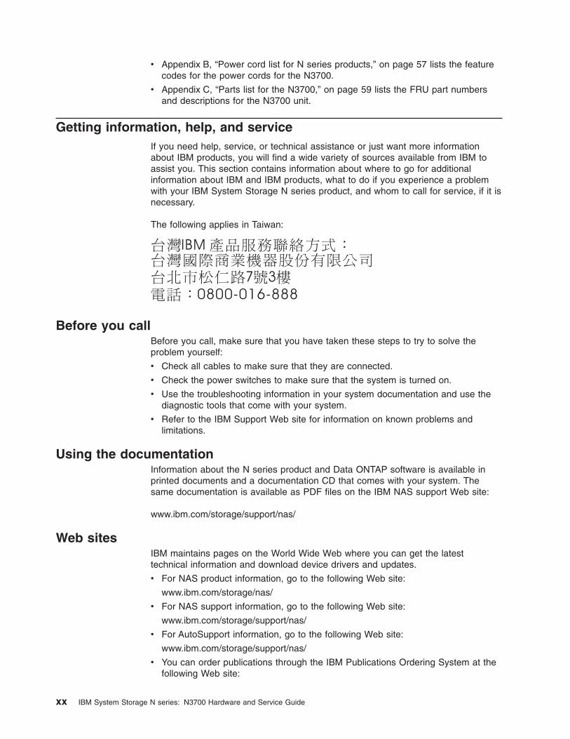
Getting information, help, and service
If you need help, service, or technical assistance or just want more information
about IBM products, you will find a wide variety of sources available from IBM to
assist you. This section contains information about where to go for additional
information about IBM and IBM products, what to do if you experience a problem
with your IBM System Storage N series product, and whom to call for service, if it is
necessary.
The following applies in Taiwan:
Before you call
Before you call, make sure that you have taken these steps to try to solve the
problem yourself:
v Check all cables to make sure that they are connected.
v Check the power switches to make sure that the system is turned on.
v Use the troubleshooting information in your system documentation and use the
diagnostic tools that come with your system.
v Refer to the IBM Support Web site for information on known problems and
limitations.
Using the documentation
Information about the N series product and Data ONTAP software is available in
printed documents and a documentation CD that comes with your system. The
same documentation is available as PDF files on the IBM NAS support Web site:
www.ibm.com/storage/support/nas/
Web sites
IBM maintains pages on the World Wide Web where you can get the latest
technical information and download device drivers and updates.
v For NAS product information, go to the following Web site:
www.ibm.com/storage/nas/
v For NAS support information, go to the following Web site:
www.ibm.com/storage/support/nas/
v For AutoSupport information, go to the following Web site:
www.ibm.com/storage/support/nas/
v You can order publications through the IBM Publications Ordering System at the
following Web site:
xx IBM System Storage N series: N3700 Hardware and Service Guide

www.elink.ibmlink.ibm.com/public/applications/publications/
cgibin/pbi.cgi/
Accessing online technical support
For online Technical Support for your IBM N series product, visit the following Web
site:
www.ibm.com/storage/support/nas/
Hardware service and support
You can receive hardware service through IBM Integrated Technology Services.
Visit the following Web site for support telephone numbers:
www.ibm.com/planetwide/
Supported servers and operating systems
IBM N series products attach to many servers and many operating systems. To
determine the latest supported attachments, visit the following Web site and access
the IBM System Storage N series interoperability matrix:
www.ibm.com/storage/support/nas/
Firmware updates
As with all devices, it is recommended that you run the latest level of firmware,
which is embedded in Data ONTAP. If there are changes, they will be posted to the
following Web site:
www.ibm.com/storage/support/nas/
Note: If you do not see new changes on the Web site, you are running the latest
level of firmware.
Verify that the latest level of firmware is installed on your machine before contacting
IBM for technical support.
Fire suppression systems
A fire suppression system is the responsibility of the customer. The customer’s own
insurance underwriter, local fire marshal, or a local building inspector, or both,
should be consulted in selecting a fire suppression system that provides the correct
level of coverage and protection. IBM designs and manufactures equipment to
internal and external standards that require certain environments for reliable
operation. Because IBM does not test any equipment for compatibility with fire
suppression systems, IBM does not make compatibility claims of any kind nor does
IBM provide recommendations on fire suppression systems.
Conventions and terminology used in this document
This guide uses the following terminology, command conventions, format
conventions and keyboard conventions:
About this document xxi

Terminology
In this and other IBM N series documents, the term filer or storage system
describes IBM N series models that either contain internal disk storage or attach to
the disk storage expansion units specifically designed for the IBM N series storage
systems.
Note: In previous releases, the EXN2000 expansion unit was referred to as the
EXP600 expansion unit.
This guide uses the following terms:
v AT-FCX refers to the controller module of the serial advanced technology
attachment (SATA) storage expansion unit (EXN1000).
v Active-Active configuration (sometimes referred to as clustered configuration)
refers to a High Availability system with at least two nodes that share resources
to provide redundancy.
v CPU module refers to the system controller module that executes the software
on an N3700. The CPU modules are at the rear-center of the N3700 storage
system.
v Device carrier refers to the container that encases a fan/power supply unit or a
disk.
v Disk applies to any hard disk drive.
v Disk shelf or expansion unit refers to any shelf or expansion unit containing hard
disk drives.
v ESH2 refers to the controller module of the fibre-channel disk storage expansion
unit (EXN2000).
v Loop refers to the daisy-chained disk shelves (expansion units) connected to an
N3700 storage system.
v Node refers to a CPU module when used in an active-active (clustered)
configuration.
v System and storage system refer to the N3700 storage system (filer), either by
itself or with additional disk shelves.
v SES refers to SCSI enclosure services.
Command conventions
You can enter commands on the system console or from any client that can obtain
access to the storage system using a Telnet session. In examples that illustrate
commands executed on a UNIX® workstation, the command syntax and output
might differ, depending on your version of UNIX.
Formatting conventions
The following table lists different character formats used in this guide to set off
special information.
xxii IBM System Storage N series: N3700 Hardware and Service Guide
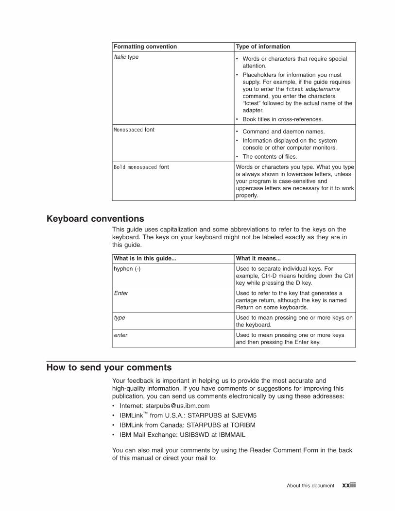
Formatting convention Type of information
Italic type v Words or characters that require special
attention.
v Placeholders for information you must
supply. For example, if the guide requires
you to enter the fctest adaptername
command, you enter the characters
“fctest” followed by the actual name of the
adapter.
v Book titles in cross-references.
Monospaced font v Command and daemon names.
v Information displayed on the system
console or other computer monitors.
v The contents of files.
Bold monospaced font Words or characters you type. What you type
is always shown in lowercase letters, unless
your program is case-sensitive and
uppercase letters are necessary for it to work
properly.
Keyboard conventions
This guide uses capitalization and some abbreviations to refer to the keys on the
keyboard. The keys on your keyboard might not be labeled exactly as they are in
this guide.
What is in this guide... What it means...
hyphen (-) Used to separate individual keys. For
example, Ctrl-D means holding down the Ctrl
key while pressing the D key.
Enter Used to refer to the key that generates a
carriage return, although the key is named
Return on some keyboards.
type Used to mean pressing one or more keys on
the keyboard.
enter Used to mean pressing one or more keys
and then pressing the Enter key.
How to send your comments
Your feedback is important in helping us to provide the most accurate and
high-quality information. If you have comments or suggestions for improving this
publication, you can send us comments electronically by using these addresses:
v Internet: [email protected]
v IBMLink™ from U.S.A.: STARPUBS at SJEVM5
v IBMLink from Canada: STARPUBS at TORIBM
v IBM Mail Exchange: USIB3WD at IBMMAIL
You can also mail your comments by using the Reader Comment Form in the back
of this manual or direct your mail to:
About this document xxiii

International Business Machines Corporation
Information Development
Dept. GZW
9000 South Rita Road
Tucson, AZ 85744–0001
U.S.A.
xxiv IBM System Storage N series: N3700 Hardware and Service Guide

Chapter 1. Preparing for the installation
This chapter provides an overview of the entire IBM System Storage N series
N3700 system installation process, hardware specifications, and the appropriate
documentation references for the procedures. Refer to the Installation and Setup
Instructions for your storage system for further information about installing your
equipment.
This chapter discusses the following topics:
v “Understanding the differences between early and current N3700 CPU modules”
v “Required manuals, tools and equipment” on page 2
v “Handling static-sensitive devices” on page 2
v “Planning and organizing the installation” on page 3
Understanding the differences between early and current N3700 CPU
modules
N3700 storage systems with system serial numbers between 13-00001 and
13-01000 shipped with an early CPU module design. (In general, these are N3700
systems that shipped prior to January 31, 2006.) Current N3700 systems (with
system serial numbers 13-01001 and higher) ship with the current CPU module
design, which uses different Fibre Channel connectors. (In general, these are
N3700 systems that shipped after January 31, 2006.)
Regardless of the CPU module design, all N3700 storage systems offer the same
functionality. Field repairs or upgrades may use the current CPU module design on
any N3700 system.
The early CPU module is easily distinguished from the current CPU module design
by the rear port labeling, shown in Figure 1. The early CPU module uses an
integrated SFP for Fibre Channel Port C (used for third-party devices), and it uses a
special HSS connector for Fibre Channel Port B to connect the N3700 to expansion
units.
The current CPU module design uses pluggable SFP connections for both Fibre
Channel ports. The current CPU module labeling is shown in Figure 2 on page 2.
The SFP required for connections to the Fibre Channel Port C (used for third-party
devices) is included with all N3700s that ship with the current CPU module design.
For Port B (used for connections to expansion units), an SFP is required only for
connections using optical cables (recommended). The SFP for Port B is shipped
with the cables ordered with your expansion unit.
Example: No additional disk shelves
Figure 1. Port labeling for early N3700 CPU module designs
© Copyright IBM Corp. 2005, 2006 1

Attention: Depending on the design of your N3700 CPU module, direct
connections to expansion units must be made with either Fibre Channel copper
cables or Fibre Channel optical cables, as described in the following bullets:
v For direct connections to N3700 early CPU module designs: Use
NAS-to-EXP Fibre Channel copper cables (FC #2020 or 2022). For attachment to
an N3700 Model A10, one NAS-to-EXP Fibre Channel copper cable is required.
For attachment to an N3700 Model A20, two NAS-to-EXP Fibre Channel copper
cables are required.
v For direct connections to N3700 current CPU module designs: Use an
LC-to-LC Fibre Channel optical cable and two SFPs for attachment to an N3700
Model A10. Use two LC-to-LC Fibre Channel optical cables and four SFPs for
attachment to an N3700 Model A20.
Required manuals, tools and equipment
You need the following manuals:
v Installation and Setup Instructions for your N3700 storage system
v IBM System Storage N series Data ONTAP Software Setup Guide for your
version of Data ONTAP, if applicable
v IBM System Storage N series Data ONTAP Cluster Installation and
Administration Guide or IBM System Storage N series Data ONTAP Active-Active
Configuration Guide for your version of Data ONTAP, if applicable
You need to supply the following tools and equipment:
v Ethernet LAN cables
v Fibre Channel cables
v Console (for example, a PC or laptop) and a serial null modem cable
v #2 Phillips screwdriver
v Pointed tool for setting termination switches
v 7-mm nut driver
v Grounding leash and ESD strap
Note: To verify your shipping contents, see the IBM System Storage N3700
Installation and Setup Instructions.
Handling static-sensitive devices
CAUTION:
The N3700 uses electronic components that are sensitive to static electricity.
Static discharge from your clothing or other fixtures around you can damage
these components. Put on an antistatic ESD strap and grounding leash to free
yourself of static electricity before touching any electronic components.
C BATerm
On
Off
B
Example: No additional disk shelves
Figure 2. Port labeling for current N3700 CPU module designs
2 IBM System Storage N series: N3700 Hardware and Service Guide

Attention: Static electricity can damage electronic devices and your system. To
avoid damage, keep static-sensitive devices in their static-protective packages until
you are ready to install them.
To reduce the possibility of electrostatic discharge (ESD), observe the following
precautions:
v Limit your movement. Movement can cause static electricity to build up around
you.
v Handle the device carefully, holding it by its edges or its frame.
v Do not touch solder joints, pins, or exposed printed circuitry.
v Do not leave the device where others can handle and possibly damage the
device.
v While the device is still in its static-protective package, touch it to an unpainted
metal part of the system unit for at least two seconds. This drains static electricity
from the package and from your body.
v Remove the device from its package and install it directly into your system unit
without setting it down. If it is necessary to set the device down, place it in its
static-protective package. Do not place the device on your system unit cover or
on a metal table. Take additional care when handling devices during cold weather
because heating reduces indoor humidity and increases static electricity.
Planning and organizing the installation
This section identifies the shipment contents and the rules and regulations you
need to observe for the proper installation of your N3700. It also provides an
overview of the entire system installation process and the appropriate
documentation references for the procedures.
For detailed information, see the following topics:
v “Hardware specifications”
v “Rules for installing the N3700 in a rack” on page 4
v “Guide to the installation process ” on page 5
Hardware specifications
The following table lists the characteristics and requirements for your hardware.
DANGER
Three people are required to lift the N3700 during installation. Do not
remove the disk drives or drive blank covers to reduce the weight.
Table 1. N3700 characteristics hardware specifications
Physical characteristics
Weight With maximum
number of disk drives
78.8 lbs (35.8 kg)
Empty 50.6 lbs (23 kg)
Rack units 3U
Height 5.25 in. (13.3 cm)
Width 17.6 in. (44.8 cm)
Depth 20 in. (50.9 cm)
Chapter 1. Preparing for the installation 3

Table 1. N3700 characteristics hardware specifications (continued)
Clearance dimensions
Front-cooling All versions 6 in. (15.3 cm)
Rear-cooling All versions 12 in. (30.5 cm)
Rear-maintenance All versions 12 in. (30.5 cm)
Environmental requirements
Note: Operating at the extremes of the following environmental requirements might
increase the risk of device failure.
Operating temperature maximum range 50° F to 104° F
(10° C to 40° C)
Operating temperature recommended range 68° F to 77° F
(20° C to 25° C)
Nonoperating temperature range -40° F to 149° F
(-40° C to 65° C)
Relative humidity 10 to 90%
noncondensing
Recommended operating temperature
relative humidity range
40 to 55%
Maximum wet bulb temperature 28° C (82° F)
Maximum altitude 3050 m (10,000 ft.)
Acoustic level 56.4 dBA @ 23° C
5.64 bels @ 23° C
Electrical requirements
Input voltage, V 100-120/200-240
Input current actual, A 4/2
Maximum electrical power 100 to 120 VAC, 7
A/200 to 240 VAC,
3.5 A; 50/60Hz
Input power actual, with all drives writing, W 440
Input power actual, by JEL measurements,
W
389
Thermal dissipation, BTU/hr 1,215
Inrush current, A @ V 25 @ 110/50 @ 220
Rules for installing the N3700 in a rack
You need to observe the following rules and restrictions when installing an N3700 in
a standard 19-inch (48.26 cm) equipment rack with mounting rails:
4 IBM System Storage N series: N3700 Hardware and Service Guide

32 kg (70.5 lb)
CAUTION:
Use safe practices when lifting.
v You must work with two other people.
DANGER
The N3700 unit is extremely heavy. To avoid injuring yourself or
damaging the N3700, you must work with at least two other people when
you install the N3700 in the rack.
v Install the N3700 storage system at the bottom of the rack. Installing the N3700
storage system at the bottom of the rack adds support for the expansion units.
DANGER
Install the equipment from the bottom up when installing it in a movable
rack. This helps prevent the rack from tipping over and seriously injuring
you or someone else.
v When installing expansion units in a rack, do not exceed the maximum storage
limit for your N3700 storage system.
v Make sure that the ID on the back panel of each expansion unit matches the ID
specified on its label.
v Always install the expansion units fully loaded. Do not remove the disk drives or
drive blank covers to reduce the weight.
v For information on grounding expansion units, refer to the IBM System Storage
N3700 Installation and Setup Instructions.
Guide to the installation process
The following table provides a guide to the storage system installation process.
Refer to the IBM System Storage N3700 Installation and Setup Instructions for
complete installation details.
Table 2. Installation process procedures
Stage Procedure
Is the procedure
required? For instructions, see...
1 Install the N3700 storage
system in a freestanding
rack.
Yes The Installation and
Setup Instructions that
came with your N3700
storage system.
2 Connect the N3700
storage system to the
network.
Yes “Connecting your N3700
storage system to a
network” on page 7, or
the Installation and
Setup Instructions for
your storage system.
Chapter 1. Preparing for the installation 5
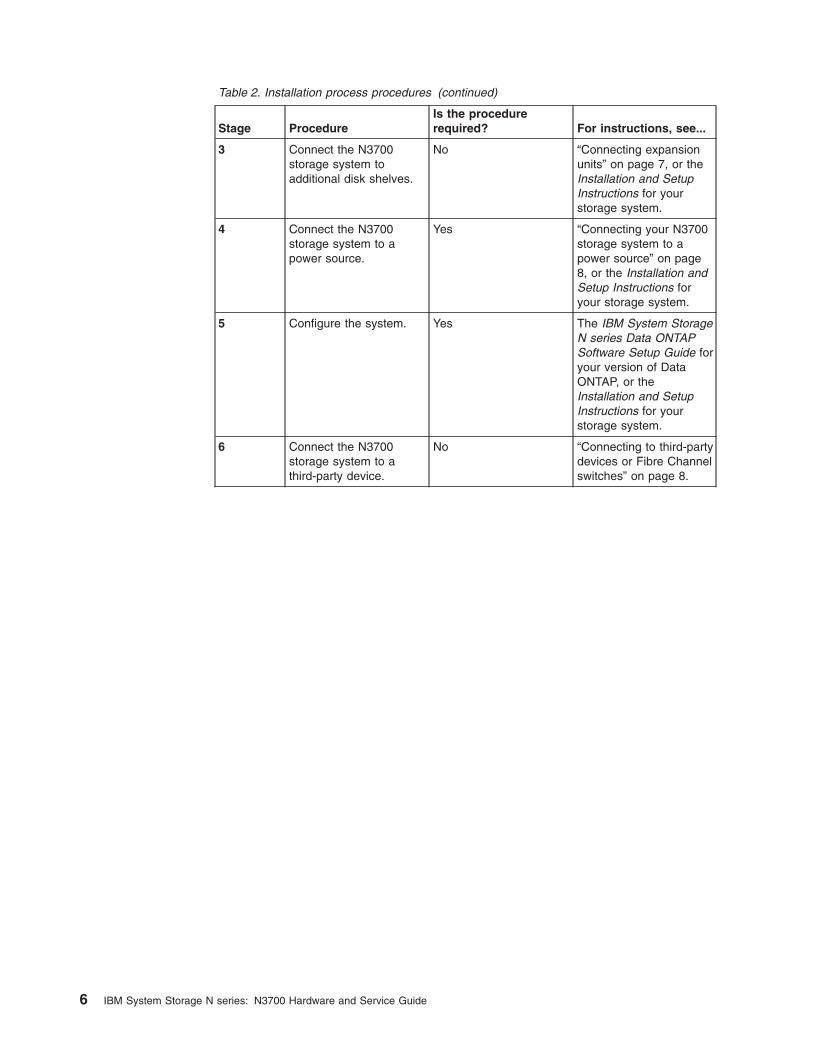
Table 2. Installation process procedures (continued)
Stage Procedure
Is the procedure
required? For instructions, see...
3 Connect the N3700
storage system to
additional disk shelves.
No “Connecting expansion
units” on page 7, or the
Installation and Setup
Instructions for your
storage system.
4 Connect the N3700
storage system to a
power source.
Yes “Connecting your N3700
storage system to a
power source” on page
8, or the Installation and
Setup Instructions for
your storage system.
5 Configure the system. Yes The IBM System Storage
N series Data ONTAP
Software Setup Guide for
your version of Data
ONTAP, or the
Installation and Setup
Instructions for your
storage system.
6 Connect the N3700
storage system to a
third-party device.
No “Connecting to third-party
devices or Fibre Channel
switches” on page 8.
6 IBM System Storage N series: N3700 Hardware and Service Guide

Chapter 2. Connecting an N3700 storage system
This chapter describes how to connect an N3700 storage system in the following
topics:
v “Handling fiber-optic cables”
v “Connecting your N3700 storage system to a network”
v “Connecting expansion units”
v “Connecting your N3700 storage system to a power source” on page 8
v “Connecting to third-party devices or Fibre Channel switches” on page 8
v “Connecting your N3700 storage system to an ASCII terminal console” on page 9
Handling fiber-optic cables
Before you use fiber-optic cables, read the following precautions.
Attention: To avoid damage to the fiber-optic cables, follow these guidelines:
v Do not route the cable along a folding cable-management arm.
v When attaching to a device on slide rails, leave enough slack in the cable so that
it does not bend to a radius of less than 38 mm (1.5 in.) when extended or
become pinched when retracted.
v Route the cable away from places where it can be snagged by other devices in
the rack cabinet.
v Do not overtighten the cable straps or bend the cables to a radius of less than 38
mm (1.5 in.).
v Do not put excess weight on the cable at the connection point. Be sure that the
cable is well supported.
CAUTION:
Data processing environments can contain equipment transmitting on
system links with laser modules that operate at greater than Class 1
power levels. For this reason, never look into the end of an optical fiber
cable or open receptacle.
Connecting your N3700 storage system to a network
Each node of your N3700 storage system connects to the network. If you have an
active-active (clustered) system both nodes need to connect to the network. For
information that describes how to connect your N3700, refer to the Installation and
Setup Instructions for your storage system.
Connecting expansion units
You can connect additional expansion units to an N3700. For information that
describes how to connect your N3700 storage system up to a maximum of three
expansion units, see the Installation and Setup Instructions for your storage system.
On all N3700 storage systems, Port B is designated for use in connections to
expansion units.
Note: The N3700 only operates at 1 Gbps. Make sure that the speed setting
switches on the expansion units are set to 1Gb.
© Copyright IBM Corp. 2005, 2006 7

The N3700 load board feature enables the N3700 (A10 and A20) to operate in a
SATA-only storage environment. If the N3700 load board is ordered, the N3700 is
ordered with no Fibre Channel hard drives and only EXN1000s (SATA drives) are
attached to the storage controller.
Attention: If your N3700 storage system shipped with load boards, exactly two
load boards are installed in the system. The two load boards must be installed in
bays 0 and 1.
Attention: Depending on the design of your N3700 CPU module, direct
connections to expansion units must be made with either Fibre Channel copper
cables or Fibre Channel optical cables, as described in the following bullets. Copper
or optical cables are ordered with the expansion unit.
v For direct connections to N3700 early CPU module designs: Use
NAS-to-EXP Fibre Channel copper cables (FC #2020 or 2022). For attachment to
an N3700 Model A10, one NAS-to-EXP Fibre Channel copper cable is required.
For attachment to an N3700 Model A20, two NAS-to-EXP Fibre Channel copper
cables are required.
v For direct connections to N3700 current CPU module designs: Use an
LC-to-LC Fibre Channel optical cable and two SFPs for attachment to an N3700
Model A10. Use two LC-to-LC Fibre Channel optical cables and four SFPs for
attachment to an N3700 Model A20.
For more information about the differences between the early and current N3700
CPU module designs, see “Understanding the differences between early and
current N3700 CPU modules” on page 1.
Connecting your N3700 storage system to a power source
The N3700 storage systems and expansion unit disk shelves are shipped with
redundant power supplies, referred to as PSU1 and PSU2. Each power supply has
its own AC power cord. You should have separate circuit breakers for each power
supply to ensure power redundancy.
For information on connecting your N3700 to a power source, see the Installation
and Setup Instructions for your storage system.
Connecting to third-party devices or Fibre Channel switches
You can connect third-party devices to your N3700 storage system through an
optical Fibre Channel interface using any Fibre Channel port on the back of the
chassis. Refer to the documentation that comes with the third-party device for
connection information.
Attention: On all N3700 storage systems, Port C is designated for use in
connections to third-party devices.
Rules for connecting the third-party devices
Observe the following rules for connecting the third-party devices:
v Port C is designated for use in connections to third-party devices. Port C is the
leftmost port on the bottom CPU module.
v For N3700 storage systems with the current CPU module design, you must plug
an SFP module into port C before cabling or terminating it.
8 IBM System Storage N series: N3700 Hardware and Service Guide

Note: N3700 storage systems with the current CPU module design ship with the
SFP module required for Port C. The early CPU module design uses an
integrated SFP for Fibre Channel Port C, so no external SFP module is
required for connections to Port C in early CPU module designs.
For more information about the differences between the early and current N3700
CPU module designs, see “Understanding the differences between early and
current N3700 CPU modules” on page 1.
v Use a fiber-optic cable that is:
– Appropriate to the Fibre Channel connection on your N3700 storage system
– Of an approved length for the third-party device
Note: See the documentation for the third-party device.
v Check the Interoperability Matrix at the following Web site to verify support for
your third-party device:
www.ibm.com/storage/support/nas/
An unsupported tape backup device might cause the N3700 storage system to
halt.
v For additional information about Fibre Channel cables, see the following Web
site:
www.ibm.com/storage/support/nas/
Connecting your N3700 storage system to an ASCII terminal console
The ASCII terminal console enables you to monitor the boot process, helps you
configure your N3700 storage system after it boots, and enables you to perform
system administration.
ASCII terminal console wiring
The following table lists the RJ-45 connection pinout of the N3700 console port on
the CPU module for use in connecting to your ASCII terminal console.
Table 3. RJ-45 connection pinout for the ASCII terminal wiring
Pin number Signal
1 Connected to pin 8
2 Not connected
3 TXD (from N3700 storage system)
4 GND
5 GND
6 RXD (to N3700 storage system)
7 Not connected
8 Connected to pin 1
DB-9 to RJ-45 console adapter pin connections
You use the included DB-9 to RJ-45 console adapter to connect an ASCII terminal
console to your N3700 storage system. Its purpose is to convert the RJ-45 pinout
on the N3700 storage system to a DB-9 pinout.
The following table lists the console adapter pin number connections between the
DB-9 male connector and the RJ-45 connector.
Chapter 2. Connecting an N3700 storage system 9

Table 4. Console adapter pin number connections
DB-9 male Connects
to
RJ-45
Pin number Signal Pin number Signal
1 Not connected - 1 Not connected
4 Not connected - 2 Not connected
3 TXD
3 TXD
5 GND
4 GND
6 Not connected - 5 Not connected
2 RXD
6 RXD
7 Not connected - 7 Not connected
8 Not connected - 8 Not connected
9 Not connected - - -
Connecting to an ASCII terminal console
To connect an ASCII terminal console to the N3700 storage system, complete the
following steps.
1. Use the following communications parameters.
Table 5. Communication parameters
Parameter Setting
Baud 9600
Data bit 8
Parity None
Stop bits 1
Flow control None
Note: See your terminal documentation for information about changing your
ASCII console terminal settings.
2. Connect a DB-9 serial cable to the DB-9 end of the DB-9 to RJ-45 console
adapter. Then connect the RJ-45 end of the console adapter to the console port
on the N3700 storage system CPU module. Finally, connect the other end of the
serial cable to the ASCII terminal.
10 IBM System Storage N series: N3700 Hardware and Service Guide

Chapter 3. Configuring an N3700 storage system
This chapter describes how to configure an N3700 storage system in the following
topics:
v “Configuring the N3700 storage system”
v “Configuring the Fibre Channel port” on page 17
Configuring the N3700 storage system
These instructions address the initial setup of Data ONTAP software on a N3700
storage system. The instructions include planning worksheets and installation
procedures for the following tasks:
v Gathering and recording information about the two nodes in “System setup
information worksheet.”
v Assigning disks to each node, as needed, in “Disk assignments” on page 12.
v Configuring the system at initial boot by completing the instructions in “Booting
your N3700 storage system for the first time” on page 14.
Attention: If you have a dual-controller N3700 (2863–A20), assign disks to each
node using the “Disk ownership worksheet” on page 13.
System setup information worksheet
You need the following information to complete the setup script. See “Setup script
questions” on page 16 for an example of the setup script questions.
Attention: If you are configuring a single-controller N3700 (2863–A10), complete
information for Node B only. Node A is not present in the N3700 2863–A10.
Table 6. System setup worksheet
Setup parameters Node B
Node A (not present in
N3700 2863–A10)
Host name:
Network configuration information
Virtual interfaces:
IP address-first interface,
e0a:
IP address-second interface,
e0b:
Netmask-first interface, e0a:
Netmask-second interface,
e0b:
Media type/speed (100tx-fd,
100tx, auto [100/1000])-first
interface, e0a:
Media type/speed (100tx-fd,
100tx, auto
[100/1000])-second interface,
e0b:
Flow control (none, receive,
send, full)-e0a:
© Copyright IBM Corp. 2005, 2006 11

Table 6. System setup worksheet (continued)
Setup parameters Node B
Node A (not present in
N3700 2863–A10)
Flow control (none, receive,
send, full)-e0b:
Enable jumbo frames?-first
interface, e0a:
Enable jumbo
frames?-second interface,
e0b:
IP address or name of default
gateway:
IP address or name of
administration host: (Leave
blank for root access to /etc
from any NFS client)
Where is filer located? (Text
string)
Do you want to run DNS
resolver?
Do you want to run NIS
client?
Disk assignments
In the N3700 storage system, each node must have ownership of at least one SES
disk in each disk shelf in the system. For example, in a single disk shelf system,
Node A could own the disk in bay 0, and Node B would then own the disk in bay 1.
In a factory-configured system, one node has ownership of one SES bay disk and
the other node owns the second SES bay disk. In addition, each node has
ownership of one parity disk and one spare disk. Node B owns disks 0b.16, 0b.18,
and 0b.20, and Node A owns disks 0b.17, 0b.19, and 0b.21. The balance of the
disks are unowned.
If you add storage to your N3700 storage system, it arrives with unowned disks.
You must assign ownership of the SES disks to the appropriate node.
Notes:
1. Always install the hard disk drives sequentially in adjacent drive bays in the
N3700, starting with drive bay 0 and continuing from right to left.
2. You can change the disk ownership pattern after initial setup. For information
about how to change disk ownership, see the IBM System Storage N series
Data ONTAP Storage Management Guide for your version of Data ONTAP.
Figure 3 on page 13 identifies the SES bays in the N3700 storage system or in an
expansion unit disk shelf.
Note: N3700 systems with the load board feature must contain no Fibre Channel
disks. If the load feature is ordered for your N3700, all disk drive bays except
bays 0 and 1 contain disk drive blanks. Bays 0 and 1 contain N3700 load
boards.
12 IBM System Storage N series: N3700 Hardware and Service Guide

Disk ownership worksheet
Complete the following worksheet to determine disk assignments for your
active-active (clustered) configuration. Identify any disks whose ownership you want
to change, and mark in the worksheet which node will own the disk. You should use
this sheet to check ownership during the setup process.
Table 7. Disk shelf 1 and disk shelf 2 disk ownership worksheet
Bay Disk shelf 1 Disk shelf 2
Disk ID Node A Node B Disk ID Node A Node B
0 0b.16 SES disk 0b.32 SES disk
1 0b.17 SES disk 0b.33 SES disk
2 0b.18 0b.34
3 0b.19 0b.35
4 0b.20 0b.36
5 0b.21 0b.37
6 0b.22 0b.38
7 0b.23 0b.39
8 0b.24 0b.40
9 0b.25 0b.41
10 0b.26 0b.42
11 0b.27 0b.43
12 0b.28 0b.44
13 0b.29 0b.45
Table 8. Disk shelf 3 and disk shelf 4 disk ownership worksheet
Bay Disk shelf 3 Disk shelf 4
Disk ID Node A Node B Disk ID Node A Node B
Disk 0b.29
These disks are owned by one node (e.g. node A)
These disks are owned by the other node (e.g. node B)
SES bays
Bay 0Disk 0b.16Bay 1
Disk 0b.17
These disks are unowned and must be assigned to either node in order to work
Bay 14
Figure 3. SES bays example
Chapter 3. Configuring an N3700 storage system 13

Table 8. Disk shelf 3 and disk shelf 4 disk ownership worksheet (continued)
0 0b.48 SES disk 0b.64 SES disk
1 0b.49 SES disk 0b.65 SES disk
2 0b.50 0b.66
3 0b.51 0b.67
4 0b.52 0b.68
5 0b.53 0b.69
6 0b.54 0b.70
7 0b.55 0b.71
8 0b.56 0b.72
9 0b.57 0b.73
10 0b.58 0b.74
11 0b.59 0b.75
12 0b.60 0b.76
13 0b.61 0b.77
Booting your N3700 storage system for the first time
To boot your active-active (clustered) configuration for the first time, complete the
following steps for the appropriate node.
1. Complete the system setup worksheet for each node, as described in “System
setup information worksheet” on page 11.
2. Complete the disk ownership worksheet, as described in “Disk ownership
worksheet” on page 13.
3. Check that the disk shelf IDs and terminate switches are properly set, and
confirm that the system is properly grounded.
Confirm that the system console is properly connected and running.
4. Turn on the power first to the disk shelves, if applicable, and then to the N3700
storage system.
Result: The system begins to boot and stops at the first installation question,
which is displayed on each node’s console window:
Please enter the new hostname []:
5. Answer the installation questions for each node:
Node B
Go to the system console for Node B and answer the installation
questions for that node, using the information you collected in the
“System setup information worksheet” on page 11. When asked for the
takeover address, make sure that you enter the IP address for Node A,
if you have an active-active (clustered) configuration.
Node A (if an active-active [clustered] configuration)
Go to the system console for Node A and answer the installation
questions for that node, using the information you collected in the
“System setup information worksheet” on page 11. When asked for the
takeover address, make sure that you enter the IP address for Node
B.
Note: When you encounter the Timezone question, you can press Enter to
accept the default setting, if you do not know how to set the timezone.
14 IBM System Storage N series: N3700 Hardware and Service Guide
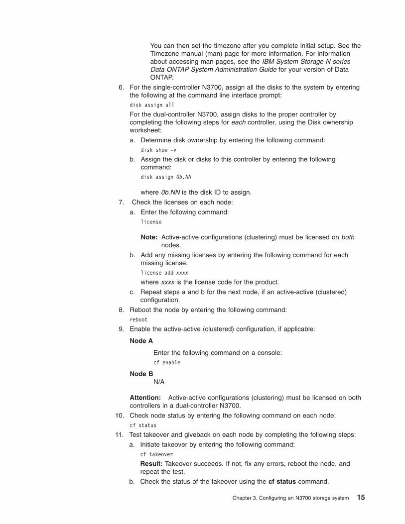
You can then set the timezone after you complete initial setup. See the
Timezone manual (man) page for more information. For information
about accessing man pages, see the IBM System Storage N series
Data ONTAP System Administration Guide for your version of Data
ONTAP.
6. For the single-controller N3700, assign all the disks to the system by entering
the following at the command line interface prompt:
disk assign all
For the dual-controller N3700, assign disks to the proper controller by
completing the following steps for each controller, using the Disk ownership
worksheet:
a. Determine disk ownership by entering the following command:
disk show -v
b. Assign the disk or disks to this controller by entering the following
command:
disk assign 0b.NN
where 0b.NN is the disk ID to assign.
7. Check the licenses on each node:
a. Enter the following command:
license
Note: Active-active configurations (clustering) must be licensed on both
nodes.
b. Add any missing licenses by entering the following command for each
missing license:
license add xxxx
where xxxx is the license code for the product.
c. Repeat steps a and b for the next node, if an active-active (clustered)
configuration.
8. Reboot the node by entering the following command:
reboot
9. Enable the active-active (clustered) configuration, if applicable:
Node A
Enter the following command on a console:
cf enable
Node B
N/A
Attention: Active-active configurations (clustering) must be licensed on both
controllers in a dual-controller N3700.
10. Check node status by entering the following command on each node:
cf status
11. Test takeover and giveback on each node by completing the following steps:
a. Initiate takeover by entering the following command:
cf takeover
Result: Takeover succeeds. If not, fix any errors, reboot the node, and
repeat the test.
b. Check the status of the takeover using the cf status command.
Chapter 3. Configuring an N3700 storage system 15
c. Give back the node by entering the following command:
cf giveback
d. Check the status of the active-active (clustered) configuration using the cf
status command.
e. Repeat steps a through c for the next node.
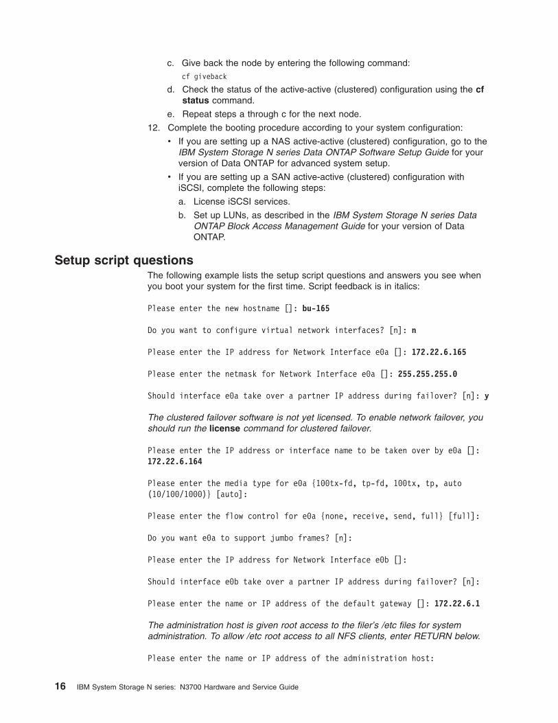
12. Complete the booting procedure according to your system configuration:
v If you are setting up a NAS active-active (clustered) configuration, go to the
IBM System Storage N series Data ONTAP Software Setup Guide for your
version of Data ONTAP for advanced system setup.
v If you are setting up a SAN active-active (clustered) configuration with
iSCSI, complete the following steps:
a. License iSCSI services.
b. Set up LUNs, as described in the IBM System Storage N series Data
ONTAP Block Access Management Guide for your version of Data
ONTAP.
Setup script questions
The following example lists the setup script questions and answers you see when
you boot your system for the first time. Script feedback is in italics:
Please enter the new hostname []: bu-165
Do you want to configure virtual network interfaces? [n]: n
Please enter the IP address for Network Interface e0a []: 172.22.6.165
Please enter the netmask for Network Interface e0a []: 255.255.255.0
Should interface e0a take over a partner IP address during failover? [n]: y
The clustered failover software is not yet licensed. To enable network failover, you
should run the license command for clustered failover.
Please enter the IP address or interface name to be taken over by e0a []:
172.22.6.164
Please enter the media type for e0a {100tx-fd, tp-fd, 100tx, tp, auto
(10/100/1000)} [auto]:
Please enter the flow control for e0a {none, receive, send, full} [full]:
Do you want e0a to support jumbo frames? [n]:
Please enter the IP address for Network Interface e0b []:
Should interface e0b take over a partner IP address during failover? [n]:
Please enter the name or IP address of the default gateway []: 172.22.6.1
The administration host is given root access to the filer’s /etc files for system
administration. To allow /etc root access to all NFS clients, enter RETURN below.
Please enter the name or IP address of the administration host:
16 IBM System Storage N series: N3700 Hardware and Service Guide

Please enter timezone [GMT]: PST8PDT
Where is the filer located? []: orlab
Do you want to run DNS resolver? [n]: y
Please enter DNS domain name [xxx]:
You can enter up to three nameservers
Please enter the IP address for first nameserver []:
Do you want another nameserver? [y]: n
Do you want to run NIS client? [n]: n
Press the Return key to continue.
Setting the administrative (root) password for bu-165 ...
New password:
Retype new password:
Configuring the Fibre Channel port
The N3700 storage system CPU module provides two independent Fibre Channel
ports, identified as B and C:
v You use the B port to communicate to the expansion unit.
v The C port has an external optical connector on the rear of the N3700 storage
system. You can configure the C port to be used in initiator mode to
communicate with tape backup devices, such as in a TapeSAN backup
configuration.
Note: For N3700 storage systems with the current CPU module design, you must
plug an SFP module into port C before cabling or terminating it. Port C is the
leftmost port on the bottom CPU module.
Fibre Channel port C does not support mixed initiator/target mode. The default
mode for port C is initiator mode. You do not need to configure the port.
N3700 storage system active-active (clustered) configurations
N3700 storage system active-active (clustered) configurations must be cabled to
switches that support public loop topology. To connect an N3700 storage system to
a fabric topology that includes switches that only support point-to-point topology,
such as McDATA Director class switches, you must connect the active-active
(clustered) configuration to an edge switch and use this switch as a bridge to the
fabric. For information about specific switch models supported and fabric
configuration guidelines, see the IBM System Storage N series Data ONTAP Block
Access Management Guide for your version of Data ONTAP at the following Web
site:
www.ibm.com/storage/support/nas/
Chapter 3. Configuring an N3700 storage system 17
Configuring for initiator mode
To configure the N3700 storage system for initiator mode, complete the following
steps.
1. Remove the FCP license by entering the following command:
license delete fcp
Example:
n3700a> license delete fcp
Fri Dec 5 14:59:02 EST [n3700a: fcp.service.shutdown:info]: FCP service
shutdown
cf.takeover.on_panic is changed to off
A reboot is required for TapeSAN service to become available.
unlicensed fcp.
FCP disabled.
n3700a> Fri Dec 5 14:59:02 EST [n3700a: rc:notice]: fcp unlicensed
2. Reboot the system by entering the following command:
reboot
3. After the reboot, verify that port C is in initiator mode by entering the following
command:
sysconfig
Example:
n3700a> sysconfig
NetApp Release xxx: Mon Aug 25 02:20:04 PDT 2003
System ID: 0084165669 (n3700a); partner ID: 0084165671 (n3700b)
System Serial Number: 379589 (n3700a)
slot 0: System Board
Processors: 2
Processor revision: B2
Processor type: 1250
Memory Size: 1022 MB
slot 0: FC Host Adapter 0b
14 Disks: 952.0GB
1 shelf with EFH
slot 0: FC Host Adapter 0c
slot 0: SB1250-Gigabit Dual Ethernet Controller
e0a MAC Address: 00:a0:98:00:d5:90 (100tx-fd-up)
e0b MAC Address: 00:a0:98:00:d5:91 (auto-unknown-cfg_down)
slot 0: NetApp ATA/IDE Adapter 0a (0x00000000000001f0)
0a.0 122MB
Note: In the above example, Fibre Channel port C is identified as FC Host
Adapter 0c.
4. Enable port C by entering the following command.
storage enable adapter 0c
Example:
n3700a> storage enable adapter 0c
Mon Dec 8 08:55:09 GMT [rc:notice]: Onlining Fibre Channel adapter 0c.
host adapter 0c enable succeeded
For more information about configuring your SAN, see the IBM System Storage N
series Data ONTAP Block Access Management Guide for your version of Data
ONTAP.
18 IBM System Storage N series: N3700 Hardware and Service Guide

Chapter 4. Monitoring your system
This chapter identifies the location of the various LEDs on your N3700 storage
system and explains how to interpret LEDs for basic monitoring.
Note: The quick reference card in the slide-out tray at the base of your N3700
storage system describes the functions of each LED on your N3700 storage
system and the suggested course of action.
This chapter discusses the following topics:
v “Monitoring the front operation panel ”
v “Monitoring the power supply” on page 21
v “Monitoring the Fibre Channel disk” on page 22
v “Monitoring the CPU module ” on page 23
Monitoring the front operation panel
The front operation panel has five LEDs and a disk shelf ID display. The LEDs
indicate whether your system is functioning normally or whether there are problems
with the hardware. You can also identify any hardware failure associated with the
front operation panel of the N3700 storage system from the error messages
displayed on your system console.
Location of LEDs
Figure 4 shows the location of the disk shelf ID display and the front panel LEDs.
Note: See “Interpreting the front panel LEDs” on page 20 for an explanation of
what the LEDs mean.
Power
FaultLoop ALoop BSystem
Disk shelf ID display
Figure 4. Disk shelf ID display and the front panel LEDs
© Copyright IBM Corp. 2005, 2006 19

About the disk shelf ID display
The disk shelf ID display shows the current disk shelf number setting from the rear
shelf ID switch on the back of the N3700 storage system. For the N3700 storage
system, the default and recommended setting for the ID switch is “1.”
Interpreting the front panel LEDs
The following illustration is of the first sheet of the quick reference cards that come
with your N3700. It shows the normal and fault conditions that the LEDs indicate
and recommends a corrective action.
Use the following table to interpret the front panel LEDs on an N3700 storage
system.
Table 9. N3700 front panel LEDs
Description
N3700 storage system LEDs
Action item Power Activity A Status A Activity B Status B
Normal
operation
Green on Green on
or flashing
Amber off Green on
or flashing
Amber off None
NOTE:
NOTE:
Populate drive bays 0 & 1 for enclosure service.
Drive bays 0 & 1
Legend
ON
OFF
CONTINUOUSBEEP
20 SEC. INTER.
1 SEC. BEEP
FLASH
ON OR OFF
N3700
Verify that Data ONTAP software is bootedand check console messages. If the failure stillexists, contact IBM Service and Support.
TM
Figure 5. LED indications of normal and fault conditions
20 IBM System Storage N series: N3700 Hardware and Service Guide

Table 9. N3700 front panel LEDs (continued)
Description
N3700 storage system LEDs
Action item Power Activity A Status A Activity B Status B
System fault
detected
Green on Green off Amber on Green on
or flashing
Amber off 1. Check the LEDs on the
modules at the rear of the
N3700 storage system.
2. Check the system console
for detailed messages.
3. Run diagnostics on the
system. See the IBM System
Storage N series Diagnostics
Guide for more information.
4. Contact IBM technical
support.
System fault
detected
Green on Green on
or flashing
Amber off Green off Amber on
Monitoring the power supply
The N3700 storage system power supply has four LEDs. The LEDs indicate
whether the power supply or the integrated fan module is functioning normally or
whether there are problems with the hardware. You can also identify any hardware
failure associated with the power supplies from the error messages displayed on
your system console.
A normal functioning power supply shows the green LED on the far left as on, with
the rest of the amber LEDs off. A power supply fault turns on the appropriate amber
LED, and causes the LED to turn off.
Location of LEDs
Each power supply is encased in a device carrier and housed at the rear of your
N3700 storage system. Figure 6 on page 22 shows the location of the power supply
LEDs.
Chapter 4. Monitoring your system 21

Interpreting power supply LEDs
The following table describes how to interpret the power supply LEDs.
Table 10. Power supply LED interpretation
Fault
condition Description
LEDs
PSU status
normal
AC missing for
this PSU
Fan
fault
Output voltage, current,
temperature fault
N Normal operation On Off Off Off
1 Power supply
failure
Off Off Off On
2 Fan failure Off Off On Off
3 No power to this
PSU
Off On Off On
Monitoring the Fibre Channel disk
The N3700 storage system Fibre Channel disk has two LEDs. The LEDs indicate
whether the disk is functioning normally or whether there are problems with the
hardware.
Location of LEDs
Figure 7 on page 23 shows the location of the Fibre Channel disk LEDs.
PSU status normal
Power
Fan LED
AC LED
Figure 6. Power supply LED location
22 IBM System Storage N series: N3700 Hardware and Service Guide

Interpreting Fibre Channel disk LEDs
Use the following table to interpret the disk LEDs.
Table 11. Fibre Channel disk LED interpretation
LED 1
(green) LED 2 (amber) State
Off Off No drive installed.
On/Blink off Off Drive installed and operational.
On Flashes 1 second on and 1 second off SES device identification set.
On or off On SES device fault bit set.
On or off Flashes 3 seconds on and 1 second
off
Disk port isolated (either port).
Monitoring the CPU module
The CPU module has several LEDs. The LEDs indicate whether the CPU module,
Fibre Channel ports, and network connections are functioning normally.
Location of LEDs on the CPU module
Figure 8 on page 24 shows the location of the Ethernet and Fibre Channel LEDs at
the rear of the CPU module.
Amber Green
Figure 7. Fibre Channel disk LEDs
Chapter 4. Monitoring your system 23

Interpreting Ethernet LEDs on an N3700 storage system
Use the following table to interpret the Ethernet port LEDs on the N3700 storage
system CPU module.
Table 12. Ethernet LED interpretation
Link LED (green) Activity LED (amber) State
Off Off Network connection is not
present.
On Off Network connection is
present but there is no data
input or output occurring.
On On/blinking Network connection is
present and data input and
output is occurring.
Interpreting Fibre Channel LEDs on an N3700 storage system
Use the following table to interpret the Fibre Channel LEDs on the N3700 storage
system CPU module.
Table 13. Fibre Channel LED interpretation
Fault LED
(amber)
Fibre Channel
B LED (green)
Fibre Channel
C LED (green) State Action
Off On On Normal None.
Off Off On Loop B fault Fibre Channel B
loop is open and
needs to be
fixed.
Off On Off Loop C fault Fibre Channel C
loop is open and
needs to be
fixed.
On On On CPU module
fault
See Note below.
1
Fibre Channel C LEDFault LED
Fibre Channel B LED
Activity LED (amber)Link LED (green)
Figure 8. Ethernet and Fibre Channel LEDs
24 IBM System Storage N series: N3700 Hardware and Service Guide

Table 13. Fibre Channel LED interpretation (continued)
Fault LED
(amber)
Fibre Channel
B LED (green)
Fibre Channel
C LED (green) State Action
On Off On Loop B fault and
module fault
See Note below.
On On Off Loop C fault and
module fault
See Note below.
Note: Perform the following steps until the problem is resolved:
1. Check the cables at the rear of the system.
2. Make sure that the 1 Gb/2 Gb switches are set to 1 Gb.
3. Check all terminate switches. Last shelf in the loop must be set to On. All
other shelves must be set to Off.
4. If Fibre Channel C port is unused, install the Fibre Channel terminator or
ignore the Fibre Channel C LED. It is alright for the LED to be off if the
port is not used.
5. Run diagnostics to isolate the failure and decide whether CPU module
replacement is necessary. See the IBM System Storage N series
Diagnostics Guide for more information.
6. Call IBM technical support to replace the CPU module.
Chapter 4. Monitoring your system 25

26 IBM System Storage N series: N3700 Hardware and Service Guide

Chapter 5. Replacing N3700 storage system devices
This chapter describes how to replace disks, CPU modules, and other devices in
your N3700 storage system.
This chapter discusses the following topics:
v “Replacing a disk”
v “Replacing a drive blank cover or N3700 load board” on page 28
v “Replacing the CPU module” on page 28
v “Replacing the SDRAM DIMM on the CPU module” on page 37
v “Replacing the CompactFlash card on the CPU module” on page 38
v “Replacing a power supply” on page 39
Replacing a disk
You can replace a disk in your storage system or disk shelf for any reason.
However, the most common reason is disk failure. If a disk fails, the N3700 storage
system logs a warning message to the system console indicating which disk failed.
About replacing a disk in your storage system
Replacing a disk in the storage system consists of the following procedures:
v “Removing a disk”
v “Installing a disk”
Removing a disk
To remove a disk, complete the following steps.
1. Enter one of the following commands, as appropriate.
v To remove a disk that is a member of a volume, enter disk fail disk_name.
v To remove a spare disk, enter disk remove disk_name.
Either command causes the amber fault LED on the disk to illuminate. For more
information about LEDs, see “Monitoring the Fibre Channel disk” on page 22.
For more information about disk commands, see the IBM System Storage N
series Data ONTAP Storage Management Guide for your version of Data
ONTAP.
2. Wait 30 seconds for the disk to stop spinning.
3. Put on the antistatic ESD strap and grounding leash.
4. To remove the disk, press down on its release mechanism with one hand while
grasping the top flange of the storage system with the other hand. Gently slide
the disk out of your storage system.
CAUTION:
When removing a disk, use two hands to support its weight.
Attention: If you have any empty disk drive bays, make sure to install a cover
over the empty slot to ensure proper cooling.
Installing a disk
To install a disk, complete the following steps.
1. Put on the antistatic ESD strap and grounding leash.
2. Orient the device carrier so that the release mechanism is at the top.
© Copyright IBM Corp. 2005, 2006 27

Note: The disks on your storage system use special drive keys to prevent the
use of nonqualified disks in your storage system. If the device carrier
does not slide into the open guide slot, check to make sure that the disk
drive is qualified for use in your N3700 storage system.
3. Insert the device carrier into the guide slot in the N3700 storage system and
gently push it in until it stops. Lift the handle on the drive carrier to engage the
drive with the backplane, and push it until you see the release mechanism click
into place.
Attention: Do not slam the device carrier into place.
4. From the console screen, assign the disk to the CPU module receiving the disk
by entering the following command:
disk assign disk_name
Replacing a drive blank cover or N3700 load board
Replacing a drive blank cover or N3700 load board in the storage system consists
of the following procedures:
v “Removing a drive blank cover or N3700 load board”
v “Installing a drive blank cover or N3700 load board”
Attention: If your N3700 storage system shipped with load boards, exactly two
load boards are installed in the system. The two load boards must be installed in
bays 0 and 1.
Removing a drive blank cover or N3700 load board
To remove a drive blank cover or N3700 load board, complete the following steps.
1. Put on the antistatic ESD strap and grounding leash.
2. To remove the drive blank cover or N3700 load board, press down on its
release mechanism with one hand while grasping the top flange of the storage
system with the other hand. Gently slide the device out of your storage system.
CAUTION:
When removing a drive blank cover or N3700 load board, use two hands
to support its weight.
Attention: If you have any empty disk drive bays, make sure to install a cover
over the empty slot to ensure proper cooling.
Installing a drive blank cover or N3700 load board
To install a drive blank cover or N3700 load board, complete the following steps.
1. Put on the antistatic ESD strap and grounding leash.
2. Orient the drive blank cover or N3700 load board so that the release
mechanism is at the top.
3. Insert the drive blank cover or N3700 load board into the guide slot in the
N3700 storage system and gently push it in until it stops. Lift the handle on the
drive carrier to engage the device with the backplane, and push it until you see
the release mechanism click into place.
Attention: Do not slam the drive blank cover or N3700 load board carrier into
place.
Replacing the CPU module
Call IBM technical support if you need to replace the CPU module
28 IBM System Storage N series: N3700 Hardware and Service Guide
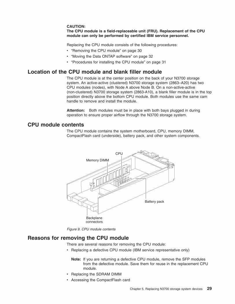
CAUTION:
The CPU module is a field-replaceable unit (FRU). Replacement of the CPU
module can only be performed by certified IBM service personnel.
Replacing the CPU module consists of the following procedures:
v “Removing the CPU module” on page 30
v “Moving the Data ONTAP software” on page 32
v “Procedures for installing the CPU module” on page 31
Location of the CPU module and blank filler module
The CPU module is at the center position on the back of your N3700 storage
system. An active-active (clustered) N3700 storage system (2863–A20) has two
CPU modules (nodes), with Node A above Node B. On a non-active-active
(non-clustered) N3700 storage system (2863-A10), a blank filler module is in the top
position directly above the bottom CPU module. Both modules use the same cam
handle to remove and install the module.
Attention: Both modules must be in place with both bays plugged in during
operation to ensure proper airflow through the N3700 storage system.
CPU module contents
The CPU module contains the system motherboard, CPU, memory DIMM,
CompactFlash card (underside), battery pack, and other system components.
Reasons for removing the CPU module
There are several reasons for removing the CPU module:
v Replacing a defective CPU module (IBM service representative only)
Note: If you are returning a defective CPU module, remove the SFP modules
from the defective module. Save them for reuse in the replacement CPU
module.
v Replacing the SDRAM DIMM
v Accessing the CompactFlash card
Backplaneconnectors
CPU
Battery pack
Memory DIMM
Figure 9. CPU module contents
Chapter 5. Replacing N3700 storage system devices 29

v System upgrade and conversion options (IBM service representative only)
Removing the CPU module
To remove the CPU module, complete the following steps.
1. Do one of the following:
v Before removing the CPU module, on a non-active-active (non-clustered)
2863-A10, shut down the N3700 storage system by entering the following
command at the console:
halt
Attention: Always use the halt command to perform a clean shutdown.
v If you are performing an unplanned CPU module replacement on a
non-active-active (non-clustered) 2863-A10, if possible, shut down the N3700
storage system by entering the following command at the console:
halt
v Before removing the CPU module on an active-active (clustered) N3700
storage system, determine which module is to be replaced. From the partner
CPU module, perform a takeover operation by entering the following
command:
cf takeover
v Before removing the CPU module on an active-active (clustered) N3700
storage system, where the partner node did or did not perform a takeover,
proceed to Step 2.
2. Put on the antistatic ESD strap and attach the grounding leash to the N3700
storage system chassis.
3. Disconnect all cables to the CPU module that you are replacing.
Note: If you are using SFPs, make sure you remove them as well.
4. At the rear-center of your N3700 storage system, using your thumb and index
finger of both hands, press the cam mechanism levers in the middle of the CPU
module to release it.
Figure 10 on page 31 shows how to release the cam mechanism.
30 IBM System Storage N series: N3700 Hardware and Service Guide

5. Carefully pull the cam handle so that the CPU module slides out from the
chassis. The CPU module has a travel distance of approximately 10 inches
(25.4 centimeters).
6. To finish servicing a component on the CPU module, see the appropriate
procedure in this chapter and then proceed to “Procedures for installing the
CPU module.”
Note: To replace a defective CPU module, contact your IBM service
representative.
Procedures for installing the CPU module
Attention: Before you can install the replacement CPU module, you need to
move the CompactFlash card from the old CPU module to the replacement CPU
module, as described in “Moving the Data ONTAP software” on page 32.
There are three separate cases to consider when installing a CPU module. To
correctly install the new CPU module, you must first perform the tasks in “Moving
the Data ONTAP software” on page 32, and then choose one of the following three
procedures, based on your system criteria:
v “Installing the module in a non-active-active system” on page 32
v “Installing the module in an active-active (clustered) system with cf disabled” on
page 33
v “Hot-swapping a module in an active-active (clustered) system while in takeover
mode” on page 34
Figure 10. Cam mechanism
Chapter 5. Replacing N3700 storage system devices 31

Moving the Data ONTAP software
The Data ONTAP software is installed on the CompactFlash card of the old CPU
module. The CompactFlash card on the replacement CPU module is blank. To get
the correct version of Data ONTAP onto the replacement CPU module, you need to
move the CompactFlash card from the old CPU module to the replacement CPU
module.
To install the correct version of Data ONTAP onto the replacement CPU module,
complete the following steps.
1. Put on the antistatic ESD strap and grounding leash.
2. On the bottom side of the old CPU module, remove the CompactFlash card.
Use your thumb to apply pressure to the exposed surface of the card, while
gently sliding the card out of the socket.
3. Repeat the same procedure by removing the CompactFlash card from the
replacement CPU module.
4. Install the old CompactFlash card into the replacement CPU module by
orienting the card so that the pin slots on the card engage properly with the pins
inside the socket, and then gently sliding the card into place until it is firmly
seated in the socket.
Attention: Damage to the card socket and card can result if you do not orient
the card properly during insertion.
5. Install the blank CompactFlash card from the replacement CPU module into the
old CPU module and return the old CPU module to IBM.
6. Proceed with one of the following sections to install your replacement CPU
module:
v “Installing the module in a non-active-active system”
v “Installing the module in an active-active (clustered) system with cf disabled”
on page 33
v “Hot-swapping a module in an active-active (clustered) system while in
takeover mode” on page 34
Installing the module in a non-active-active system
To install the CPU module in a non-active-active (non-clustered) system, complete
the following steps.
Bottom ofCPU module
CompactFlashcard
Figure 11. CompactFlash card
32 IBM System Storage N series: N3700 Hardware and Service Guide

1. Put on the antistatic ESD strap and grounding leash.
2. Connect all cables to the CPU module before inserting the module into its CPU
module bay. For more information, see “Connecting your N3700 storage
system to a network” on page 7.
3. From the back of your N3700 storage system, slide the module into the CPU
module bay and push the cam mechanism levers into place.
4. Set the terminate switch on the CPU module to the proper position.
5. If power was removed, reconnect the power to your N3700 storage system
and turn on the power switch on both power supplies. See “Connecting your
N3700 storage system to a power source” on page 8.
6. At the console screen, bring your system to the CFE (common firmware
environment) prompt, or halt the system if it tries to autoboot Data ONTAP, by
entering the following command:
halt
7. Run diagnostics on the new CPU module by entering the following command:
boot_diags
8. At the diagnostics prompt, run all tests by entering the following command:
all
Note: The RTC (real-time clock) uses the same battery as NVMEM. If the
battery is disconnected and drained, the RTC loses its time, which can
cause some tests to fail on startup. One solution is to ignore the
message and set the clock in Data ONTAP later, or set the clock from
within diagnostics and repeat the diagnostics tests.
9. Exit diagnostics by entering the following command:
exit
See the IBM System Storage N series Diagnostics Guide at the following Web
site for more information:
www.ibm.com/storage/support/nas/
10. Boot Data ONTAP by entering the following command:
boot_ontap
11. Press Ctrl-C to enter the maintenance menu.
12. Select option 5 to enter maintenance mode.
13. Fix disk ownership.
To see all disks and the old CPU module name, enter the following command:
disk show -v
14. Reassign disk ownership by entering the following command:
disk reassign -o systemname
15. Shut down the N3700 storage system by entering the following command at
the console:
halt
16. Boot Data ONTAP by entering the following command:
boot_ontap
Installing the module in an active-active (clustered) system with
cf disabled
To install the CPU module in an active-active (clustered) configuration system
where the partner node has not performed a takeover, complete the following steps.
1. Put on the antistatic ESD strap and grounding leash.
Chapter 5. Replacing N3700 storage system devices 33

2. Connect all cables to the CPU module before inserting the module into its CPU
module bay. For more information, see “Connecting your N3700 storage
system to a network” on page 7.
3. From the back of your N3700 storage system, slide the module into the CPU
module bay and push the cam mechanism levers into place.
4. Set the terminate switch on the CPU module to the proper position.
5. If power was removed, reconnect the power to your N3700 storage system
and turn on the power switch on both power supplies. See “Connecting your
N3700 storage system to a power source” on page 8.
6. Press Ctrl-C to stop rebooting.
7. Run diagnostics on the new CPU module by entering the following command:
boot_diags
8. At the diagnostics prompt, run all tests by entering the following command:
all
9. Exit diagnostics by entering the following command:
exit
See the IBM System Storage N series Diagnostics Guide at the following Web
site for more information:
www.ibm.com/storage/support/nas/
10. Boot Data ONTAP by entering the following command:
boot_ontap
11. Press Ctrl-C to enter the maintenance menu.
12. Select option 5 to enter maintenance mode.
13. Fix disk ownership.
To see all disks and the old CPU module name, enter the following command:
disk show -v
14. Reassign disk ownership by entering the following command:
disk reassign -o systemname
15. Shut down the N3700 storage system by entering the following command at
the console:
halt
16. Boot Data ONTAP by entering the following command:
boot_ontap
Hot-swapping a module in an active-active (clustered) system
while in takeover mode
To install the CPU module in an active-active (clustered) system where the partner
node has performed a takeover, complete the following steps.
1. Put on the antistatic ESD strap and grounding leash.
2. Connect all cables to the CPU module before inserting it into the module bay.
For more information, see “Connecting your N3700 storage system to a
network” on page 7.
3. Set the terminate switch on the CPU module to the proper position.
4. From the back of your N3700 storage system, slide the module into the
module bay and push the cam mechanism levers into place.
5. If you installed a new CompactFlash card, the card might not contain any data,
in which case you need to boot your N3700 storage system from a remote
image.
34 IBM System Storage N series: N3700 Hardware and Service Guide
6. Capture the output from the console. Be sure to write down the system ID
number, as shown in bold in the following example. The output should look
something like this:
Loading: 0xffffffff80001000/8500653 Entry at 0xffffffff80001000
Closing network.
Starting program at 0xffffffff80001000
Press CTRL-C for special boot menu
.
.
WARNING: there do not appear to be any disks attached to the system.
Check that disks have been assigned ownership to this system (ID 84166052)
using the ’disk show’ and ’disk assign’ commands from maintenance mode
No root volume found.
Rebooting...
7. Press Ctrl-C to stop rebooting.
8. Reassign disk ownership for the new CPU module from the partner node with
the new system ID, by entering the following commands at the takeover
prompt:
priv set advanced
9. Enter the following command using the recorded system ID from Step 6, for
example:
disk reassign -d 84166052
The console screen should display something resembling the following:
node x(takeover)> priv set advanced
node x(takeover)*> disk reassign -d 84166083
Disk ownership will be updated on all disks previously belonging to Filer
with serial number 12345.
Would you like to continue (y/n)?
10. Select y.
11. Verify disk ownership. Make sure that all disks that were supposed to be
reassigned, were reassigned.
To see all disks, enter the following command:
disk show -v
12. The new CPU module should see the disk on the next reboot, accompanied by
the following message:
Waiting for cluster giveback
From the partner node, enter the following command:
cf giveback
Note: If the giveback does not succeed, see the IBM System Storage N series
Data ONTAP System Administration Guide and IBM System Storage N
series Data ONTAP Software Setup Guide for your version of Data
ONTAP for additional information.
Replacing the battery on the CPU module
If the battery inside your CPU module fails, you need to replace it. Replacing the
battery consists of the following tasks:
v Removing the CPU module
v Replacing the battery
Chapter 5. Replacing N3700 storage system devices 35

v Reinstalling the CPU module
To replace the battery, complete the following steps:
1. Put on the antistatic ESD strap and grounding leash.
2. Remove the CPU module by following the procedure in “Removing the CPU
module” on page 30.
3. Disconnect the battery wire from the CPU module motherboard.
4. At the side of the CPU module, remove the four screws holding the battery
housing, and remove the battery. See Figure 12.
CAUTION:
Danger of explosion if battery is incorrectly replaced. Replace only with
the same or equivalent type recommended by the manufacturer. Dispose
of used batteries according to manufacturer’s instructions. For more
information, see “Battery return program” on page ix.
5. Install the new battery by placing it into the battery housing, and secure the
battery housing to the CPU module using the four screws.
6. Reconnect the battery wire to the CPU module.
7. Reinstall the CPU module.
8. After turning on your system, run diagnostics on the new battery. See the IBM
System Storage N series Diagnostics Guide for more information.
Note: The battery is rechargeable, and diagnostics might indicate a low charge
after installation. This is normal. The battery will reach a full charge after
your storage system has been turned on for several hours.
9. Check and set the date and time values on your storage system. Replacing the
battery will likely cause these values to get reset.
Batteryconnection
Battery
Batteryhousing
Figure 12. Battery housing in CPU module
36 IBM System Storage N series: N3700 Hardware and Service Guide

Replacing the SDRAM DIMM on the CPU module
The SDRAM DIMM is on the CPU module motherboard. You must remove the CPU
module from the chassis before replacing the DIMM.
Required memory configuration
The N3700 storage system supports one 1 GB, 2.5V 184P DDR SDRAM DIMM.
The DIMM slot is inside the CPU module.
Attention: All DIMMs must be listed on the IBM Approved Parts List. Contact IBM
Sales to obtain this list. Unapproved DIMMs have not been tested for reliability and
might cause system downtime.
Replacing the SDRAM DIMM
To remove the SDRAM DIMM, complete the following steps.
1. Put on the antistatic ESD strap and grounding leash.
2. Perform a clean system shutdown before removing the DIMM.
Attention: Perform a clean system shutdown before removing the DIMM.
Removing the DIMM without first performing a clean system shutdown can
result in data loss.
3. Remove the CPU module containing the DIMM to be replaced.
Follow the procedure in “Removing the CPU module” on page 30.
4. Unplug the battery pack cable from the motherboard before removing the
DIMM.
5. Push apart the latches on either side of the DIMM to release the DIMM from
its slot, as shown in Figure 13.
6. Pull the DIMM out of the slot.
7. Set the old DIMM aside in an antistatic bag.
8. Pick up the new DIMM by its top corners to avoid damaging the components.
9. Insert the DIMM straight into the slot. The DIMM fits tightly in the slot, but
should go in easily. If not, realign the DIMM with the slot and try again.
Attention: Visually inspect the DIMM to verify that it is evenly aligned and
fully inserted into the slot; otherwise, the edge connector on the DIMM does
not make complete contact with the slot.
10. Push carefully but firmly on the top edge of the DIMM until the latches snap
into place.
Figure 13. Releasing DIMM latches
Chapter 5. Replacing N3700 storage system devices 37

11. Plug the battery cable back into the motherboard.
12. Reinstall the CPU module. See “Procedures for installing the CPU module” on
page 31.
13. After turning on your system, run diagnostics on the SDRAM DIMM. See the
IBM System Storage N series Diagnostics Guide for more information.
Replacing the CompactFlash card on the CPU module
The CompactFlash card is on the back side of the CPU module. Replacing the
CompactFlash card consists of the following tasks:
v Removing the CPU module
v Replacing the CompactFlash card
v Reinstalling the CPU module
Replacing the CompactFlash card
To replace the CompactFlash card, complete the following steps.
1. Put on the antistatic ESD strap and grounding leash.
2. Remove the CPU module by following the procedure in “Removing the CPU
module” on page 30.
3. On the bottom side of the CPU module, remove the CompactFlash card. Use
your thumb to apply pressure to the exposed surface of the card, while gently
sliding the card out of the socket, as shown in Figure 14.
4. Install the CompactFlash card by orienting the card correctly so that the
pin-slots on the card engage properly with the pins inside the socket, and gently
sliding the card into place until it is firmly seated in the socket.
Attention: Damage to the card socket and/or card can result if you do not
orient the card properly during insertion.
5. Reinstall the CPU module. See “Procedures for installing the CPU module” on
page 31.
6. Boot your N3700 storage system from a remote image. Refer to “Performing the
netboot process from a remote image” on page 50 for more information.
7. Copy the correct Data ONTAP boot files to the CompactFlash card by entering
the following command:
Bottom ofCPU module
CompactFlashcard
Figure 14. CompactFlash card removal
38 IBM System Storage N series: N3700 Hardware and Service Guide

download
8. Test the CompactFlash card by using one of the following two options:
Table 14. CompactFlash card testing options
Option 1 Option 2
1. Reboot the N3700 storage system and
let it autoboot by entering the following
command:
reboot
2. After Data ONTAP boots, copy the boot
files to the secondary backup area of the
CompactFlash card by entering the
following command:
download
1. Shut down the N3700 storage system by
entering the following command at the
console:
halt
2. Run diagnostics by entering the following
command:
boot_diags
See the Diagnostics Guide for more
information.
3. When finished, exit diagnostics by
entering the following command:
exit
4. Boot Data ONTAP by entering the
following command:
boot_ontap
Replacing a power supply
Follow these procedures to replace a power supply in your N3700 storage system
or disk shelf:
v “Removing a power supply” on page 40
v “Installing a power supply” on page 40
Rules for replacing power supplies
When replacing the power supply in your N3700 storage system, observe the
following rules:
v You do not need to turn off the power to the N3700 storage system when you
replace one power supply at a time.
v If you are replacing both power supplies, replace them one at a time to avoid
powering down your N3700 storage system.
v Although a single fan failure in one of the power supplies is not a critical event, it
is recommended that you install a new power supply when one of the two fans in
either power supply stops working.
v When hot-swapping power supplies, replace and install the power supplies within
two minutes of each other.
Attention: Your N3700 storage system can run with one power supply for a
maximum of two minutes. The airflow through your N3700 storage system is
degraded when only one power supply is present and operating. Therefore, if the
power supplies are not replaced within two minutes of each other, the system halts
and no data is accessible.
v Have the replacement power supply close by and ready to install before
removing the old one.
Chapter 5. Replacing N3700 storage system devices 39
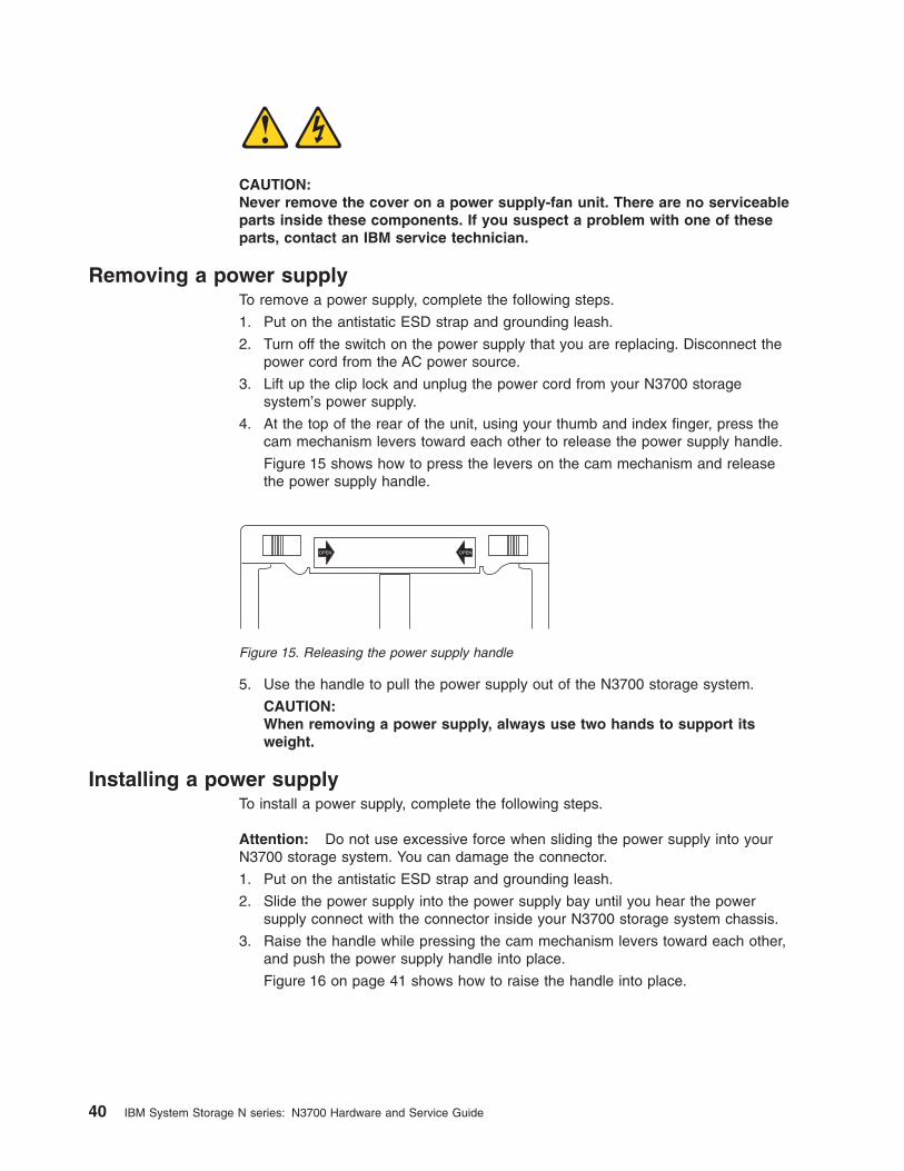
CAUTION:
Never remove the cover on a power supply-fan unit. There are no serviceable
parts inside these components. If you suspect a problem with one of these
parts, contact an IBM service technician.
Removing a power supply
To remove a power supply, complete the following steps.
1. Put on the antistatic ESD strap and grounding leash.
2. Turn off the switch on the power supply that you are replacing. Disconnect the
power cord from the AC power source.
3. Lift up the clip lock and unplug the power cord from your N3700 storage
system’s power supply.
4. At the top of the rear of the unit, using your thumb and index finger, press the
cam mechanism levers toward each other to release the power supply handle.
Figure 15 shows how to press the levers on the cam mechanism and release
the power supply handle.
5. Use the handle to pull the power supply out of the N3700 storage system.
CAUTION:
When removing a power supply, always use two hands to support its
weight.
Installing a power supply
To install a power supply, complete the following steps.
Attention: Do not use excessive force when sliding the power supply into your
N3700 storage system. You can damage the connector.
1. Put on the antistatic ESD strap and grounding leash.
2. Slide the power supply into the power supply bay until you hear the power
supply connect with the connector inside your N3700 storage system chassis.
3. Raise the handle while pressing the cam mechanism levers toward each other,
and push the power supply handle into place.
Figure 16 on page 41 shows how to raise the handle into place.
OPEN OPEN
Figure 15. Releasing the power supply handle
40 IBM System Storage N series: N3700 Hardware and Service Guide

4. Lift up the clip lock and plug the power cord into the power receptacle and
fasten it with the clip lock.
5. Plug the other end of the power cord into a grounded AC power source.
6. Turn on the power switch and confirm proper operation by checking the power
supply LEDs. See “Monitoring the power supply” on page 21.
7. After turning on your system, run diagnostics. See the IBM System Storage N
series Diagnostics Guide for more information.
Figure 16. Raising the power supply handle
Chapter 5. Replacing N3700 storage system devices 41

42 IBM System Storage N series: N3700 Hardware and Service Guide

Chapter 6. Error messages and troubleshooting
This chapter lists error messages you might encounter during the boot process.
Note: If you contact IBM technical support, please have the console messages
available.
This chapter discusses the following topics:
v “Startup error messages”
v “Environmental EMS messages” on page 47
v “Booting your N3700 storage system from a backup firmware image” on page 50
v “Troubleshooting the N3700 storage system ” on page 51
Where to get more information
The following table lists the documentation that can help you with some of the
corrective actions.
Table 15. Corrective action documentation
If you are troubleshooting... Then...
A hardware problem and need to access
your N3700 storage system
SeeChapter 5, “Replacing N3700 storage
system devices,” on page 27.
Expansion Unit problems See the hardware guide that came with your
expansion shelf.
Software problems See the IBM System Storage N series Data
ONTAP System Administration Guide and the
Data ONTAP Storage Management Guide for
your version of Data ONTAP.
Startup error messages
When you apply power to your N3700 storage system, it verifies the hardware that
is in the system, loads the operating system, and displays the Power-On Self-Test
(POST) messages on the system console.
POST messages
POST is a series of tests run from the motherboard PROM. These tests check the
hardware on the motherboard and differ depending on your system configuration.
The following series of messages are examples of POST messages displayed on
the console.
POST Messages:
HyperTransport: 400MHz
CPU type 0x1040102: 650MHz
Total memory: 0x40000000 bytes (1024MB)
Starting AUTOBOOT press any key to abort...
Loading: Failed.
Loading: 0xffffffff80001000/8604573 Entry at 0xffffffff80..
Starting program at 0xffffffff80001000
Press CTRL-C for special boot menu
© Copyright IBM Corp. 2005, 2006 43

Note: If the messages are not appearing on your system console, verify that you
are using the DB-9 to RJ-45 adapter.
Boot messages
After the boot is successfully completed, your N3700 storage system loads the
operating system. The following message is an example of the boot messages and
questions that appear on the system console of an N3700 storage system at first
boot. The exact boot messages that appear on your system console depend on
your system configuration.
Release x.x.x: Mon Oct 20 04:06:00: PDT 2003
System ID: 0084170726 ();partner ID: 0084170777
System Serial Number: 999999
slot 0: System board
Processors: 1
Processor revision: B2
Processor type: 1250
Memory size: 1022 MB
slot 0: FC Host Adapter 0b
14 disks: 952.0 GB
1 shelf with EFH
slot 0: FC Host Adapter 0b
slot 0: SB1250 Gigabit Dual Ethernet Controller
e0a MAC Address: 00:a0:98:00:e9:b3 (auto-unknow
e0a MAC Address: 00:a0:98:00:e9:b4 (auto-unknow
slot 0: NetApp ATA/IDE Adapter 0a (0x00000000000001f0)
0a.0 245MB
Please enter the new hostname []: hw-166
Do you want to configure virtual network interfaces? [n]:
Please enter the IP address for Network Interface e0a []: 172.22.6.166
Please enter the netmask for Network Interface e0a []:
Should interface e0a take over a partner IP address during failover? [n]: y
Please enter the IP address or interface name to be taken over by e0a []: 172.22.6.167
Please enter media type for e0a {100tx-fd, tp-fd, 100tx, tp, auto (10/100/1000)} [auto]:
Please enter flow control for e0a {none, receive, send, full} [full]:
Do you want e0a to support jumbo frames? [n]:
Please enter the IP address for Network Interface e0b []:
Should interface e0b take over a partner IP address during failover? [n]:
Would you like to continue setup through the web interface? [n]:
Please enter the name or IP address of the default gateway []:
The administration host is given root access to the filer’s
/etc files for system administration. To allow /etc root access
to all NFS clients enter RETURN below.
Please enter the name or IP address of the administration host:
Please enter timezone [GMT]:
Where is the filer located? []: orlab
Do you want to run DNS resolver? [n]: y
Please enter DNS domain name []:
You may enter up to 3 nameservers
Please enter the IP address for first nameserver []:
Do you want another nameserver? [y]: n
Do you want to run NIS client? [n]:
POST error messages
The following table describes the extended POST error messages that might
appear on the system console if your N3700 storage system encounters CPU-level
system errors during the POST process.
44 IBM System Storage N series: N3700 Hardware and Service Guide

Note: Always power-cycle your N3700 storage system when you receive any of the
following errors. If the system repeats the error message, follow the
corrective action for that error message.
Table 16. POST error message descriptions
Error message or code Description Corrective action
[RAMX] No physical memory was
found by the system.
This indicates that the
system doesn’t see any
memory. Try resetting the
DIMM. See “Replacing the
SDRAM DIMM on the CPU
module” on page 37.
[Cerr] Cache error. These are cache errors.
These errors indicate a bad
CPU. If a power-cycle
doesn’t fix the problem, call
your IBM service
representative to replace the
CPU module.
[Cer2] Cache error.
[EXC!] Exception. This indicates that the
system took an exception
while in firmware. If it is
repeatable, this is likely a
software bug in the firmware.
Contact IBM technical
support and provide a log of
the error. If you can’t get past
this error, boot the system
using the backup firmware
image.
[RUN!] CFE (common firmware
environment) is jumping to
executable code.
This is not an error, but
rather a progress state
indicator used to help
troubleshoot the problem.
[HELO] Very early Init code. If the system stops on one of
these error codes, there is
likely a hardware problem.
First, try Step 1 below. If this
doesn’t fix the problem,
proceed to the subsequent
steps until the problem is
fixed.
1. Power off the system,
then power it back on.
2. Try booting with the
backup firmware image.
See “Booting your N3700
storage system from a
backup firmware image”
on page 50.
3. Call your IBM service
representative to replace
the CPU module.
[L1CI] L1 cache INIT.
[L2CI] L2 Cache INIT.
[TST1] Simple POST test: cache of
both levels and tags.
[CPU1] CPU1 INIT.
[cpu1] CPU1 entering IDLE loop.
Chapter 6. Error messages and troubleshooting 45

Table 16. POST error message descriptions (continued)
Error message or code Description Corrective action
[DRAM] Running on CPU0, on
memory segment 0 (that is,
program is now running in
RAM rather than flash
memory).
If the system stops on one of
these error codes, the
memory is bad or the
NVLOG subsystem
malfunctioned. To test this,
reseat the DIMM and
disconnect the battery. See
Chapter 5, “Replacing N3700
storage system devices,” on
page 27.
If that fails to clear the
problem, replace the DIMM.
See “Replacing the SDRAM
DIMM on the CPU module”
on page 37.
[Zero] Zero memory...no NVMEM.
[Keep] Keep memory...preserve
NVMEM.
[ZBSS] Zero the BSS segment.
[CODE] Zero and copy the code
segment from flash to
memory.
[DATA] Zero and copy the data
segment from flash to
memory.
[RELO] Jump to the new code
segment.
[L12F] Flush and enable caches.
[MAIN] Jump to the main CFE
memory.
[KMEM] Initialize CRDs heap.
[NVCL] Clear memory that isn’t
owned by NVMEM or CFE.
[CONS] Attach console device. Check the connection
between your N3700 storage
system and the console
device. Replace the cable if it
is defective.
[CIOK] Copy right etc. A message of this type
doesn’t indicate a specific
failure, but a general failure
of some system component.
1. Try booting with the
backup firmware image.
See “Booting your N3700
storage system from a
backup firmware image”
on page 50.
2. Call your IBM service
representative to replace
your CPU module.
[AREN] Physical memory map INIT.
[DEVI] Misc devices INIT.
[ENVI] Environmental variable
subsystem INIT.
46 IBM System Storage N series: N3700 Hardware and Service Guide

Table 16. POST error message descriptions (continued)
Error message or code Description Corrective action
[PCIH] PCI host bridge INIT. If the system stops with one
of these error codes, there is
likely a problem with either
the SB1250 chip or the
ISP2312 FC-AL chip.
1. Try booting with the
backup firmware image.
See “Booting your N3700
storage system from a
backup firmware image”
on page 50.
2. Otherwise, call your IBM
service representative to
replace the CPU module.
[PCIB] PCI try to init P2P bridges.
[PCIS] PCI device scan.
[CFE ] This message is written when
CFE jumps to the exception
handler, for whatever reason.
This is caused by either bad
hardware or a bad flash
memory.
1. Power-cycle the system.
2. Try booting with the
backup firmware image.
See “Booting your N3700
storage system from a
backup firmware image”
on page 50.
3. Otherwise, call your IBM
service representative to
replace the CPU module.
Environmental EMS messages
The following table describes the environmental EMS messages that might appear
on the system console if your N3700 storage system encounters extremes in its
operational environment.
Table 17. Environmental EMS messages
Name Parameters Description Corrective action Syslog SNMP
monitor.chassis
Fan.ok
NOTICE
fru_name
STRING
This message is
issued when the
chassis fans are
OK.
No corrective
action needed.
LOG_NOTICE:
Chassis FRU is
ok
#366: Chassis
FRU is ok
monitor.chassis
Fan.slow
ALERT
fru_name
STRING
This is a warning
message that is
issued when a
chassis fan is
spinning too
slowly.
The fan unit
should be
replaced.
LOG_ALERT:
Chassis FRU
contains at least
one fan spinning
slowly
#365: Chassis
FRU contains at
least one fan
spinning slowly
monitor.chassis
Fan.stop
ALERT
fru_name
STRING
This is a warning
message that is
issued when a
chassis fan is
stopped.
The fan unit
should be
replaced.
LOG_ALERT:
Chassis FRU
contains at least
one stopped fan
#364: Chassis
FRU contains at
least one stopped
fan
Chapter 6. Error messages and troubleshooting 47

Table 17. Environmental EMS messages (continued)
Name Parameters Description Corrective action Syslog SNMP
monitor.chassis
Fan.removed
ALERT
fan_name
STRING
This is a warning
message that is
issued when a
chassis fan is
removed.
The fan unit
should be
replaced.
LOG_ALERT:
Chassis FRU is
removed
#363: Chassis
FRU is removed
monitor.chassis
Temperature.ok
NOTICE
This message is
issued when the
chassis
temperature is
normal.
No corrective
action needed.
LOG_NOTICE:
Chassis
temperature is ok
#376: Chassis
temperature is ok
monitor.chassis
Temperature
.warm
ALERT
describe_
toowarm
STRING
This is a warning
message that is
issued when the
chassis
temperature is too
warm.
Check to see if air
conditioning units
are needed, or
whether they are
functioning
properly.
LOG_ALERT:
Chassis
temperature is too
warm
#372: Chassis
temperature is too
warm
monitor.chassis
Temperature
.cool
ALERT
describe_ toocool
STRING
This is a warning
message that is
issued when the
chassis
temperature is too
cool.
Raise the ambient
temperature
around the N3700
storage system.
LOG_ALERT:
Chassis
temperature is too
cool
#372: Chassis
temperature is too
cool
monitor.shut
down.chassis
OverTemp
CRIT
describe_ toohot
STRING
This message is
issued just before
shutdown,
indicating the
chassis
temperature is too
hot.
Check to see if air
conditioning units
are needed, or
whether they are
functioning
properly.
LOG_CRIT:
Chassis
temperature is too
hot
#371: Chassis
temperature is too
hot
monitor.shut
down.chassis
UnderTemp
CRIT
describe_ toocold
STRING
This message is
issued just before
shutdown when
the chassis
temperature
becomes too cold.
Raise the ambient
temperature
around the N3700
storage system.
LOG_CRIT:
Chassis
temperature is too
cold
#371: Chassis
temperature is too
cold
monitor.cpu
Fan.ok
INFO
cpu_number
INT
This message
indicates that a
CPU fan is OK.
No corrective
action needed.
LOG_INFO: CPU
Fan OK
#386: CPU Fan
OK
monitor.cpu
Fan.degraded
NOTICE
cpu_number
INT
This message
indicates that a
CPU fan is
degraded.
The CPU fan or
the system
motherboard
might need to be
replaced. See the
hardware and
service guide that
came with your
system.
LOG_NOTICE:
CPU Fan is slow
#383: CPU Fan is
slow
48 IBM System Storage N series: N3700 Hardware and Service Guide

Table 17. Environmental EMS messages (continued)
Name Parameters Description Corrective action Syslog SNMP
monitor.cpu
Fan.failed
NOTICE
cpu_number
INT
This message
indicates that a
CPU fan is
degraded.
The CPU fan or
the system
motherboard
might need to be
replaced. See the
hardware and
service guide that
came with your
system.
LOG_NOTICE:
CPU Fan is
stopped
#381: CPU Fan is
stopped
monitor.chassis
PowerSupplies
.ok
INFO
This message
indicates that all
power supplies
are OK.
No corrective
action needed.
LOG_INFO:
Chassis power
supplies OK
#396: Chassis
power supplies
OK
monitor.chassis
PowerSupply
.off
NOTICE
ps_number
INT
This message
indicates that a
power supply is
turned off.
Turn the power
supply on.
LOG_NOTICE:
Chassis power
supply off
#395: Chassis
power supply is
off
monitor.chassis
PowerSupply
. notPresent
NOTICE
ps_number
INT
This message
indicates that a
power supply is
not present.
Add a power
supply to the
N3700 storage
system.
LOG_NOTICE:
Chassis power
supply not
present
#394: Chassis
power supply is
not present
monitor.chassis
PowerSupply
. degraded
NOTICE
ps_number
reasonText
INT STRING
This message
indicates that a
power supply is
degraded.
A replacement
power supply
might be required.
Contact IBM
technical support
for further
instruction.
LOG_NOTICE:
Chassis power
supply is
degraded
#392: Chassis
power supply is
degraded
monitor.chassis
Power.ok
NOTICE
This messages
indicates that the
motherboard
power is OK.
No corrective
action needed.
LOG_NOTICE:
Chassis power is
OK
#406: Chassis
power is OK
monitor.chassis
Power.degraded
NOTICE
reasonText
STRING
This message
indicates that a
power supply is
degraded.
Replace the
power supplies.
1
LOG_NOTICE:
Chassis power is
degraded
#403: Chassis
power is
degraded
1 Degraded power might be caused by bad power supplies, bad wall power, or bad
components on the motherboard. If spare power supplies are available, try
replacing them to see whether that alleviates the problem. Otherwise, contact IBM
technical support for further instruction.
Chapter 6. Error messages and troubleshooting 49

Netboot process for the N3700 storage system
The netboot process enables you to boot your N3700 storage system from a
remote server if your CompactFlash media becomes damaged or unusable.
Configuration requirements for netboot servers
You can configure a system to serve boot images to IBM devices that support the
netboot process. To do so, you must configure the following items:
v HTTP and/or TFTP services on your system
v The rest of your netbooting environment to use the system as the netboot source
For example, you might configure BOOTP, DHCP, bootparamd, and/or rarpd,
depending on the specific procedure you are using.
Note: For more information about the netbooting process, see the IBM System
Storage N series System Administration Guide for your version of Data
ONTAP.
Performing the netboot process from a remote image
To perform the netboot process on an N3700 storage system from a remote image,
complete the following steps:
1. Place a Data ONTAP boot image on a local HTTP server. You can copy the
boot image from the N3700 storage system boot directory, /etc/boot/netapp-mips, or download it from the following Web site:
www.ibm.com/storage/support/nas/
2. At the N3700 storage system CFE prompt, enter one of the following
commands:
Using DHCP:
ifconfig e0a -auto
Using manual configuration:
ifconfig e0a -addr=filer_addr -mask=netmask -gw=gateway -dns=dns_addr
-domain=dns_domain
3. At the CFE prompt, enter the following command:
netboot URL
Example:
netboot http://myserver/bootimages/netapp/netapp-mips
Result: You should then see normal boot messages during the netboot process.
Note: If you performed the netboot process because your CompactFlash card is
blank or corrupted, be sure to execute the Data ONTAP download
command to copy the correct files from the disks to the CompactFlash card.
See the IBM System Storage Data ONTAP System Administration Guide for
your version of Data ONTAP for more details.
Booting your N3700 storage system from a backup firmware image
This procedure boots your N3700 storage system using a stored backup firmware
image and should only be used as a last resort.
Booting with a backup firmware image
To boot using a backup firmware image, complete the following steps:
50 IBM System Storage N series: N3700 Hardware and Service Guide

1. With the system powered off, insert a paper clip into the tiny, unmarked hole
between the console and Ethernet ports. Make sure that you can feel the button
pushing in.
2. While the button is pressed with the paper clip, turn on power to the N3700
storage system.
3. Remove the paper clip from the hole.
The result is that the N3700 storage system begins booting, showing its
progress on the console screen.
Troubleshooting the N3700 storage system
Use this table to troubleshoot specific problems with your system.
Problem Possible cause Solution
CFE (common firmware
environment) won’t boot.
Last console status code
might be [ZBSS], [L12F], or
[CERR].
This indicates that something
is wrong with the memory
DIMM.
To fix this problem, begin with the first procedure in
the following list. If that doesn’t solve the problem,
continue down to the next troubleshooting tip on the
list until the problem is solved.
v Unplug the battery in the CPU module for 5
seconds, plug the battery back in, and try booting
the N3700 storage system.
Note: Unplugging the battery might reset the clock.
v Reseat the DIMM on the CPU module.
v Replace the DIMM.
v Call your IBM service representative to replace the
CPU module.
CFE comes up but [CERR]
is printed out when booting
the kernel
This is a problem with
NVMEM. NVMEM is mainly
for power outages. Handling
the CPU module outside the
shelf while NVMEM is valid
might corrupt memory.
v If the CPU module was not handled, contact IBM
technical support.
v Otherwise, unplug the battery in the CPU module
for 5 seconds, plug the battery back in, and try
booting the N3700 storage system.
Note: Unplugging the battery might reset the clock.
CFE comes up but can’t
boot anything from the
CompactFlash card.
Contents of the CompactFlash
card are not correct.
Try entering this command at the CFE prompt, which
is equivalent to dir c: from a PC:
test fatfs ide0.0
If no errors occur and nothing is shown on the
console, the contents of the CompactFlash card are
not valid or the CompactFlash card is blank. Reinstall
Data ONTAP. Refer to “Netboot process for the N3700
storage system” on page 50 for more information.
If there is an error, replace the CompactFlash card.
Pinhole button
Figure 17. Pinhole reset button
Chapter 6. Error messages and troubleshooting 51

Problem Possible cause Solution
Real-Time Clock (RTC)
loses its time.
The rechargeable battery for
NVMEM also powers the
real-time clock. If this battery
is disconnected for more than
a few seconds or the battery
is discharged, the real-time
clock might be reset.
Plug the battery back in to the motherboard and reset
the clock to the correct time.
The N3700 storage system
does not recognize any of
the installed disk drives.
The 1 Gb/2 Gb switch is not
set to the 1 Gb position.
1. Power off the N3700 storage system.
2. Move the switch to the 1 Gb position. See Step 6
of “Connecting your N3700 storage system to a
network” on page 7.
3. Power on the N3700 storage system.
My IBM service
representative replaced a
CPU module and now the
new module can’t see the
disks
The disk ownership
mechanism ties disks to CPU
module system IDs. If your
IBM service representative
replaced a CPU module with
a new one in, the disks are
still stamped with the system
ID of the old module.
Perform a disk reassign command. Use the help
command to get the exact syntax.
I have unowned disks; why
didn’t Data ONTAP use them
to reconstruct a failed drive?
The disks need to be
“SPARES,” not “unowned.”
Assign the disks as spares.
The battery is discharged
and Data ONTAP won’t boot.
The battery voltage is too low
to hold data for 3 days during
a power-out condition.
If you turn on the machine
and let it sit at the firmware
(CFE) prompt, it does not turn
on the charger. You need to
boot Data ONTAP to get the
software to turn on the battery
charger.
You have two main options at this point:
1. Leave the N3700 storage system alone for a few
hours to let the battery charge.
2. Press Ctrl-C to override this check.
Executing a priv set advanced command and an nv
command shows you the current status of the battery
(if you pressed Ctrl-C to override the stall condition).
You can also try out the environ chassis Battery
command (note that “Battery” is case-sensitive).
In either case, the battery charger is turned on and
recharges the battery over the next few hours.
CFE failed, creating a POST
code.
CFE firmware runs a series of
Power-On-Self-Tests (POST)
before trying to load Data
ONTAP. If any of the POSTs
fail, a code is printed.
See “POST error messages” on page 44 for a
description of the error.
52 IBM System Storage N series: N3700 Hardware and Service Guide

Problem Possible cause Solution
Fibre Channel adapter B
appears to be unattached or
disconnected.
You have an open loop. Fibre
Channel needs a
closed/completed loop to
communicate.
v Check the terminate switch on the CPU module. If
an expansion shelf is attached to your system, the
terminate switch should be OFF. If there’s no
expansion shelf, you must have the terminate
switch set to ON.
v If you have expansion shelves, the last shelf must
have its terminate switch set to ON. All other
shelves in the loop (including the CPU module)
must have the terminate switches set to OFF.
v If that doesn’t fix it, you might have a faulty shelf,
drive, or cable. Try removing items until the loop
closes and then add them back until you see the
failure. While removing/adding, be sure to set the
terminate switches appropriately.
v If that still doesn’t fix it, you might have a bad
adapter on the CPU module (rare case). Call your
IBM service representative to replace the CPU
module.
The N3700 storage system
won’t stop beeping.
It is the kernel’s responsibility
to “ping” the ops panel
occasionally so the ops
panel’s watchdog timer
doesn’t start beeping.
Push the MUTE button on the back of the shelf to stop
the beeping. If beeping continues, contact IBM
technical support.
Chapter 6. Error messages and troubleshooting 53

54 IBM System Storage N series: N3700 Hardware and Service Guide

Appendix A. Recommended power line sizes
This appendix discusses how to determine the power line lengths running from your
N3700 storage system to the power source.
Recommended AC power line sizes
Longer AC power feeds need to be properly designed to preserve voltage levels to
the equipment. The wiring from the breaker panel to the power strip, which supplies
power to your N3700 storage system and disk shelves, can often exceed 50 feet.
Note: Total AC wire length = breaker to wall or ceiling outlet + extension cable or
ceiling drop.
The following table lists the recommended conductor size for 2% voltage drop for a
particular distance in feet (taken from the Radio Engineer’s Handbook).
Table 18. 110V, single phase recommended conductor sizes
110V, single-phase 20A circuit 30A circuit 40A circuit 50A circuit
25 feet 12 AWG 10 AWG 8 AWG 8 AWG
50 feet 8 AWG 6 AWG 6 AWG 4 AWG
75 feet 6 AWG 4 AWG 4 AWG 2 AWG
Table 19. 220V, single phase recommended conductor sizes
220V, single-phase 20A circuit 30A circuit 40A circuit 50A circuit
25 feet 14 AWG 12 AWG 12 AWG 10 AWG
50 feet 12 AWG 10 AWG 8 AWG 8 AWG
75 feet 10 AWG 8 AWG 6 AWG 6 AWG
The following table list the approximate equivalent wire gauge (American Wire
Gauge (AWG) to Harmonized Cordage).
Table 20. American Wire Gage to Harmonized Cordage equivalents
AWG 8 10 12
Harmonized, mm-mm
1 4.0 2.5 1.5
1 mm-mm = millimeter squared
© Copyright IBM Corp. 2005, 2006 55

56 IBM System Storage N series: N3700 Hardware and Service Guide

Appendix B. Power cord list for N series products
The following list details the power cord feature codes (FCs) for N series products.
FC 9000 (All countries)
Power cord, Rack PDU
v 27 inches
v Rated 250 V/15 A
v Product end uses C14; PDU end uses C13.
FC 9001 Europe and others
Provides power cords for Austria, Belgium, Bolivia, Bulgaria, Chile, Croatia,
Czech Republic, Egypt, Estonia, European Union, Finland, France,
Germany, Greece, Hungary, Iceland, Indonesia, Latvia, Lebanon, Lithuania,
Luxemburg, Morocco, Netherlands, Norway, Peru, Poland, Portugal,
Romania, Russia, Slovakia, Slovenia, Spain, Suriname, Sweden, Turkey
v 2.5 m (9 feet), unshielded, rated 250 V/10 A.
v Attached plug EL 211 (CEE 7-VII) designed for 200-240 V ac input.
FC 9002 United Kingdom and others
Provides power cords for United Kingdom, Costa Rica, Cyprus, Guyana,
Hong Kong, Ireland, Kuwait, Malta, Oman, Singapore, Sri Lanka
v 2.5 m (9 feet), unshielded, rated 250 V/10 A.
v Attached plug EL 210 (13A fuse) designed for 200-240 V ac input.
FC 9003 Japan
Provides power cords for Japan
v 1.83 m (6 feet), unshielded, rated 125 V/15 A.
v Attached plug EL 302 (JIS C3306) designed for 100-110 V ac input.
FC 9004 U.S., Six Feet (2 m)
Provides power cords for U.S., Canada, Mexico, Belize, Columbia, Ecuador,
El Salvador, Guatemala, Honduras, Korea, Nicaragua, Panama, Philippines,
Puerto Rico, Saudi Arabia, Thailand, Venezuela
v 1.83 m (6 feet), unshielded, rated 125 V/15 A.
v Attached plug EL 302 (Nema 5-15P) designed for 100-120 V ac input.
FC 9005 Australia, New Zealand
Provides power cords for Australia, New Zealand, Uruguay
v 2.5 m (9 feet), unshielded, rated 250 V/10 A.
v Attached plug EL 206 (AS 3112) designed for 200-240 V ac input.
FC 9006 Switzerland, Liechtenstein
Provides power cords for Switzerland, Liechtenstein
v 2.5 m (9 feet), unshielded, rated 250 V/10 A.
v Attached plug EL 203 (SEV 1011) designed for 200-240 V ac input.
FC 9007 Argentina
Provides power cords for Argentina
v 2.5 m (9 feet), unshielded, rated 250 V/10 A.
v Attached plug EL 219 (IRAM 2073) designed for 200-240 V ac input.
FC 9008 China
Provides power cords for China
v 2.5 m (9 feet), unshielded, rated 250 V/10 A.
© Copyright IBM Corp. 2005, 2006 57

v Attached plug EL 602 (GB 2099/GB 1002) designed for 200-240 V ac
input.
FC 9009 Denmark
Provides power cords for Denmark
v 2.5 m (9 feet), unshielded, rated 250 V/10 A.
v Attached plug EL 213 (DHCR 107-2-D1) designed for 200-240 V ac
input.
FC 9010 India, Pakistan, South Africa
Provides power cords for India, Macau, Pakistan, South Africa
v 2.5 m (9 feet), unshielded, rated 250 V/10 A.
v Attached plug EL 208 (BS 164-1, BS 546) designed for 200-240 V ac
input.
FC 9011 Israel
Provides power cords for Israel
v 2.5 m (9 feet), unshielded, rated 250 V/10 A.
v Attached plug EL 212 (SI 32) designed for 200-240 V ac input.
FC 9012 Italy
Provides power cords for Italy
v 2.5 m (9 feet), unshielded, rated 250 V/10 A.
v Attached plug EL 502 (CEI 23-16) designed for 200-240 V ac input.
FC 9013 North America (250 V)
Provides power cords for U.S.
v 1.83 m (6 feet), unshielded, rated 250 V/15 A.
v Attached plug EL 309 (NEMA 6-15P) designed for 200-240 V ac input.
FC 9014 Brazil
Provides power cords for Brazil
v 2.5 m (9 feet), unshielded, rated 250 V/10 A.
v Attached plug EL 211 (NBR 6147/2000) designed for 200-240 V ac input
FC 9015 Taiwan
Provides 125 V power cords for Taiwan
v 2.5 m (9 feet), unshielded, rated 125 V/15 A.
v Attached plug EL 302 (CNS 10917-3) designed for 100-120 V ac input.
FC 9016 Taiwan (250 V)
Provides 250 V power cords for Taiwan
v 1.83 m (6 feet), unshielded, rated 250 V/10 A.
v Attached plug EL 610 (CNS 10917, CNS 690) designed for 250 V ac
input.
58 IBM System Storage N series: N3700 Hardware and Service Guide

Appendix C. Parts list for the N3700
This appendix lists the FRU part numbers and descriptions for the N3700.
Subassemblies and parts
This table lists the subassembly and part FRU numbers and descriptions for the
N3700.
Table 21. Subassembly and part FRUs and descriptions
FRU Description
23R3464 ESH2 Controller
95P3015 CPU Module (supported only for early N3700 systems)
23R3946 CPU Module (supported for current N3700 systems)
23R4608 1 GB DIMM
23R4609 Compact Flash 256MB
23R4400 N3700 Bezel
23R4610 Battery
23R4544 Redundant Power Supply (AC) with Fans
95P3021 N3700 Service Card
23R4335 N3700 SFP (for use in Port C)
23R3471 Short-wave SFP (for use in Port B)
23R3461 Console Cable
23R4543 Drive blank cover
23R9270 N3700 load board
Hard disk drives
This table lists the FRU numbers and descriptions of hard disk drives for the
N3700.
Table 22. HDDs FRUs and descriptions
FRU Description
23R2964 72GB 10k FC HDD
23R2965 144GB 10k FC HDD
23R2966 300GB 10k FC HDD
23R2967 72GB 15k FC HDD
23R2968 144BG 15k FC HDD
© Copyright IBM Corp. 2005, 2006 59

Cables and connectors
This table lists the cable and connector FRU numbers and descriptions for
expansion unit cables and connectors used in connection with the N3700. These
FRUs are ordered with the expansion units.
Table 23. Cable and connector FRUs and descriptions
FRU Description
23R4601 FC Copper NAS to EXP Patch Cable, 0.5m
1
23R4602 FC Copper NAS to EXP Patch Cable, 3m
1
23R3463 FC Copper SFP to SFP Patch Cable, 0.5m
23R3465 FC Copper SFP to SFP Patch Cable, 3m
23R3471 Short-wave SFP (for use in Port B)
23R6217 1m Optical Cable, Pair, LC/LC Ends
23R5834 2m Optical Cable, Pair, LC/LC Ends
23R5835 5m Optical Cable, LC/LC Ends
1 FC Copper NAS to EXP patch cables are supported only for direct connections to
expansion units from N3700 storage systems with system serial numbers between
13-00001 and 13-01000 (in general, these are N3700 systems shipped prior to January 31,
2006).
Power cords
This table lists the power cord FRU numbers and descriptions for the N3700.
Table 24. Power cord FRUs and descriptions
FRU Description
23R3487 Power Cord, Rack PDU, 27″, 250V/10A, C13
23R3488 Power Cord, EU, 2.5m, 250V/10A, EL 211 (CEE 7-VII)
23R3489 Power Cord, UK, 2.5m, 250V/10A, EL 210 (13A Fuse)
23R3490 Power Cord, Japan, 1.83m, 125V/15A, EL 302 (JIS C3306)
23R3491 Power Cord, US, 1.83m, 125V/15A, EL 302 (Nema 5-15P)
23R3492 Power Cord, ANZ, 2.5m, 250V/10A, EL 206 (AS 3112)
23R3493 Power Cord, Swiss, 2.5m, 250V/10A, EL203 (SEV 1011)
23R3494 Power Cord, Argentina, 2.5m, 250V/10A, EL 219 (IRAM 2073)
23R3495 Power Cord, China, 2.5m, 250V/10A, EL 602 (GB 2099/GB1002)
23R3496 Power Cord, 2.5m, 250V/10A, EL213 (DHCR 107-2-D1)
23R3497 Power Cord, India/SAfrica, 2.5m, 250V/10A, EL 208 (BS164-1, BS
546)
23R3498 Power Cord, Israel 2.5m, 250V/10A, EL 212 (SI 32)
23R3499 Power Cord, Italy 2.5m, 250V/10A, EL 502 (CEI 23-16)
23R3500 Power Cord, US 94″, 250V/15A, EL 309 (NEMA 6-15P)
23R3418 Power Cord, Brazil 2.5m, 250V/10A, EL 211 (NBR6147/2000)
23R3420 Power Cord, Taiwan 2.5m, 125V/15A, EL 302 (CNS 10917-3)
23R5897 Power Cord, Taiwan 1.83m, 250V/10A, EL 610 (CNS 10917, CNS
690)
60 IBM System Storage N series: N3700 Hardware and Service Guide

Appendix D. IBM System Storage N series documentation
The following lists present an overview of the IBM System Storage N series
hardware and Data ONTAP product libraries, as well as other related documents.
You can access the documents listed in these tables at the following Web site:
www.ibm.com/storage/support/nas/
N7600 and N7800 storage systems library
v IBM System Storage N7600 and N7800 Hardware and Service Guide,
GC26-7953
v IBM System Storage N7600 and N7800 Filer Installation and Setup Instructions,
GC26-7954
v IBM System Storage N7600 and N7800 Gateway Installation and Setup
Instructions, GC26-7956
N3700 storage system library
v IBM System Storage N3700 Hardware and Service Guide, GA32-0515
v IBM System Storage N3700 Installation and Setup Instructions, GA32-0517
N5200 and N5500 filer storage systems library
v IBM System Storage N5200 and N5500 Hardware and Service Guide,
GC26-7785
v IBM System Storage N5200 and N5500 Filer Installation and Setup Instructions,
GC26-7784
v IBM System Storage N5200 and N5500 Gateway Installation and Setup
Instructions, GC26-7838
EXN1000 and EXN2000 expansion units library
v IBM System Storage EXN1000 Storage Expansion Unit Hardware and Service
Guide, GC26-7802
v IBM System Storage EXN2000 Storage Expansion Unit Hardware and Service
Guide, GA32-0516
v IBM System Storage EXN1000 and EXN2000 Installation and Setup Instructions,
GC26-7786
Data ONTAP 7.2 gateway storage systems library
v IBM System Storage N series Data ONTAP 7.2 Gateway Planning Guide,
GC26-7957
v IBM System Storage N series Data ONTAP 7.2 Gateway Integration Guide for
IBM Storage, GC26-7959
v IBM System Storage N series Data ONTAP 7.2 Gateway Integration Guide for
Hitachi Storage, GC26-7960
v IBM System Storage N series Data ONTAP 7.2 Gateway Integration Guide for
HP Storage, GC26-7961
© Copyright IBM Corp. 2005, 2006 61

v IBM System Storage N series Data ONTAP 7.2 Gateway Software Upgrade
Guide, GC26-7958
v IBM System Storage N series Data ONTAP 7.2 Gateway Software Setup,
Installation, and Management Guide, GC26-7962
v IBM System Storage N series Data ONTAP 7.2 Gateway Connecting Your
System, GC26-7990
v IBM System Storage N series Data ONTAP 7.2 Gateway Release Notes,
GC26-7955
Data ONTAP 7.1 gateway storage systems library
v IBM System Storage N series Gateway Planning Guide, GC26-7839
v IBM System Storage N series Gateway Integration Guide for IBM Storage,
GC26-7840
v IBM System Storage N series Gateway Integration Guide for Hitachi Storage,
GC26-7841
v IBM System Storage N series Gateway Integration Guide for HP Storage,
GC26-7858
v IBM System Storage N series Gateway Software Upgrade Guide, GC26-7859
v IBM System Storage N series Gateway Software Setup, Installation, and
Management Guide, GC26-7886
v IBM System Storage N series Gateway Release Notes, GC26-7837
Data ONTAP 7.2 library
v IBM System Storage N series Data ONTAP 7.2 Release Notes, GC26-7963
v IBM System Storage N series Data ONTAP 7.2 Active-Active Configuration
Guide, GC26-7964
v IBM System Storage N series Data ONTAP 7.2 File Access and Protocols
Management Guide, GC26-7965
v IBM System Storage N series Data ONTAP 7.2 Storage Management Guide,
GC26-7966
v IBM System Storage N series Data ONTAP 7.2 Data Protection Online Backup
and Recovery Guide, GC26-7967
v IBM System Storage N series Data ONTAP 7.2 Data Protection Tape Backup and
Recovery Guide, GC26-7968
v IBM System Storage N series Data ONTAP 7.2 MultiStore Management Guide,
GC26-7969
v IBM System Storage N series Data ONTAP 7.2 Network Management Guide,
GC26-7970
v IBM System Storage N series Data ONTAP 7.2 Commands: Manual Page
Reference, Volume 1, GC26-7971
v IBM System Storage N series Data ONTAP 7.2 Commands: Manual Page
Reference, Volume 2, GC26-7972
v IBM System Storage N series Data ONTAP 7.2 Upgrade Guide, GC26-7976
v IBM System Storage N series Data ONTAP 7.2 Block Access Management Guide
for iSCSI & FCP, GC26-7973
v IBM System Storage N series Data ONTAP 7.2 System Administration Guide,
GC26-7974
v IBM System Storage N series Data ONTAP 7.2 Software Setup Guide,
GC26-7975
62 IBM System Storage N series: N3700 Hardware and Service Guide

v IBM System Storage N series Data ONTAP 7.2 Core Commands Quick
Reference, GC26-7977
Data ONTAP 7.1 library
v IBM System Storage N series Data ONTAP Release Notes, GC26-7862
v IBM System Storage N series Data ONTAP Cluster Installation and
Administration Guide , GC26-7790
v IBM System Storage N series Data ONTAP 7.1 File Access and Protocols
Management Guide, GA32-0520
v IBM System Storage N series Data ONTAP 7.1 Storage Management Guide,
GA32-0521
v IBM System Storage N series Data ONTAP 7.1 Data Protection Online Backup
and Recovery Guide, GA32-0522
v IBM System Storage N series Data ONTAP 7.1 Data Protection Tape Backup and
Recovery Guide, GA32-0523
v IBM System Storage N series Data ONTAP 7.1 MultiStore Management Guide,
GA32-0524
v IBM System Storage N series Data ONTAP 7.1 Network Management Guide,
GA32-0525
v IBM System Storage N series Data ONTAP 7.1 Commands: Manual Page
Reference, Volume 1, GA32-0526
v IBM System Storage N series Data ONTAP 7.1 Commands: Manual Page
Reference, Volume 2, GA32-0527
v IBM System Storage N series Data ONTAP 7.1 Upgrade Guide, GC26-7791
v IBM System Storage N series Data ONTAP 7.1 Block Access Management Guide
for iSCSI & FCP, GA32-0528
v IBM System Storage N series Data ONTAP 7.1 System Administration Guide,
GA32-0529
v IBM System Storage N series Data ONTAP 7.1 Software Setup Guide,
GA32-0530
v IBM System Storage N series Data ONTAP 7.1 Core Commands Quick
Reference, GA32-0531
Other N series and N series-related documents
v IBM System Storage N series Filer Release Notes 7.1.0.1P1, GC26-7983
v IBM System Storage N series Error Messages and Troubleshooting, GC26-7984
v IBM System Storage N series Diagnostics Guide, GC26-7789
v IBM System Storage N series Introduction and Planning Guide, GA32-0543
v IBM System Storage N series AutoSupport Overview, GC26-7854
v IBM System Storage N series: Event-triggered AutoSupport messages for Data
ONTAP 7.1, GC26-7932
v IBM System Storage N series: Changing the cluster cfmode Setting in Fibre
Channel SAN Configurations, GC26-7876
v IBM System Storage N series Fibre Channel Configuration Guide, GC26-7835
v IBM System Storage Translated Safety Notices, GA27-4338
v IBM System Storage N series Statement of Limited Warranty In 9 Languages
GC26-7986-00 23R8907
Appendix D. IBM System Storage N series documentation 63

v IBM System Storage N series Statement of Limited Warranty In 29 Languages
GC26-7987-00
v IBM Statement of Limited Warranty Customer Notice, G550-0423-00 17R8112
v IBM Storage Solution Rack 2101 Model 200 Installation and Service Guide,
SY27-7622
64 IBM System Storage N series: N3700 Hardware and Service Guide

Notices
This information was developed for products and services offered in the U.S.A.
IBM may not offer the products, services, or features discussed in this document in
other countries. Consult your local IBM representative for information on the
products and services currently available in your area. Any reference to an IBM
product, program, or service is not intended to state or imply that only that IBM
product, program, or service may be used. Any functionally equivalent product,
program, or service that does not infringe on any IBM intellectual property right may
be used instead. However, it is the user’s responsibility to evaluate and verify the
operation of any non-IBM product, program, or service.
IBM may have patents or pending patent applications covering subject matter
described in this document. The furnishing of this document does not give you any
license to these patents. You can send license inquiries, in writing to:
IBM Director of Licensing
IBM Corporation
North Castle Drive
Armonk, N.Y. 10504-1785
U.S.A.
For additional information, visit the web at:http://www.ibm.com/ibm/licensing/contact/
The following paragraph does not apply to the United Kingdom or any other
country where such provisions are inconsistent with local law:
INTERNATIONAL BUSINESS MACHINES CORPORATION PROVIDES THIS
PUBLICATION “AS IS” WITHOUT WARRANTY OF ANY KIND, EITHER EXPRESS
OR IMPLIED, INCLUDING, BUT NOT LIMITED TO, THE IMPLIED WARRANTIES
OF NON-INFRINGEMENT, MERCHANTABILITY OR FITNESS FOR A
PARTICULAR PURPOSE. Some states do not allow disclaimer of express or
implied warranties in certain transactions, therefore, this statement may not apply to
you.
This information could include technical inaccuracies or typographical errors.
Changes are periodically made to the information herein; these changes will be
incorporated in new editions of the publication. IBM may make improvements and/or
changes in the product(s) and/or the program(s) described in this publication at any
time without notice.
Any references in this information to non-IBM web sites are provided for
convenience only and do not in any manner serve as an endorsement of those web
sites. The materials at those web sites are not part of the materials for this IBM
product and use of those web sites is at your own risk.
IBM may use or distribute any of the information you supply in any way it believes
appropriate without incurring any obligation to you.
Any performance data contained herein was determined in a controlled
environment. Therefore, the results obtained in other operating environments may
vary significantly. Some measurements may have been made on development-level
systems and there is no guarantee that these measurements will be the same on
generally available systems. Furthermore, some measurement may have been
© Copyright IBM Corp. 2005, 2006 65

estimated through extrapolation. Actual results may vary. Users of this document
should verify the applicable data for their specific environment.
Information concerning non-IBM products was obtained from the suppliers of those
products, their published announcements or other publicly available sources. IBM
has not tested those products and cannot confirm the accuracy of performance,
compatibility or any other claims related to non-IBM products. Questions on the
capabilities of non-IBM products should be addressed to the suppliers of those
products.
If you are viewing this information in softcopy, the photographs and color
illustrations may not appear.
Edition notice
© COPYRIGHT INTERNATIONAL BUSINESS MACHINES CORPORATION, 2005,
2006. All rights reserved.
U.S. Government Users — Use, duplication or disclosure restricted by GSA ADP
Schedule Contract with IBM Corp.
Trademarks
The following terms are trademarks of International Business Machines Corporation
in the United States, other countries, or both:
IBM IBMLink
IBM logo System Storage
Microsoft®, Windows®, and Windows NT® are trademarks of Microsoft Corporation
in the United States, other countries, or both.
UNIX is a registered trademark of The Open Group in the United States and other
countries.
NetApp, the Network Appliance logo, the bolt design, NetApp–the Network
Appliance Company, Data ONTAP, DataFabric, FAServer, FilerView, MultiStore,
NearStore, NetCache, SecureShare, SnapManager, SnapMirror, SnapMover,
SnapRestore, SnapVault, SyncMirror, and WAFL are registered trademarks of
Network Appliance, Inc. in the United States, and/or other countries. gFiler, Network
Appliance, SnapCopy, Snapshot, and The Evolution of Storage are trademarks of
Network Appliance, Inc. in the United States and/or other countries and registered
trademarks in some other countries. ApplianceWatch, BareMetal, Camera-to-Viewer,
ComplianceClock, ComplianceJournal, ContentDirector, ContentFabric, EdgeFiler,
FlexClone, FlexVol, FPolicy, HyperSAN, InfoFabric, LockVault, Manage ONTAP,
NOW, NetApp on the Web, ONTAPI, RAID-DP, RoboCache, RoboFiler,
SecureAdmin, Serving Data by Design, SharedStorage, Simulate ONTAP, Smart
SAN, SnapCache, SnapDirector, SnapDrive, SnapFilter, SnapLock, SnapMigrator,
SnapSuite, SnapValidator, SohoFiler, vFiler, VFM, Virtual File Manager, VPolicy, and
Web Filer are trademarks of Network Appliance, Inc. in the United States and other
countries. NetApp Availability Assurance and NetApp ProTech Expert are service
marks of Network Appliance, Inc. in the United States. Spinnaker Networks, the
Spinnaker Networks logo, SpinAccess, SpinCluster, SpinFS, SpinHA, SpinMove,
and SpinServer are registered trademarks of Spinnaker Networks, LLC in the
66 IBM System Storage N series: N3700 Hardware and Service Guide

United States and/or other countries. SpinAV, SpinManager, SpinMirror,
SpinRestore, SpinShot, and SpinStor are trademarks of Spinnaker Networks, LLC in
the United States and/or other countries.
Apple is a registered trademark and QuickTime is a trademark of Apple Computer,
Inc. in the United States and/or other countries. Microsoft is a registered trademark
and Windows Media is a trademark of Microsoft Corporation in the United States
and/or other countries. RealAudio, RealNetworks, RealPlayer, RealSystem,
RealText, and RealVideo are registered trademarks and RealMedia, RealProxy, and
SureStream are trademarks of RealNetworks, Inc. in the United States and/or other
countries.
All other brands or products are trademarks or registered trademarks of their
respective holders and should be treated as such.
Network Appliance is a licensee of the CompactFlash and CF Logo trademarks.
Network Appliance NetCache is certified RealSystem compatible.
Other company, product, or service names may be trademarks or service marks of
others.
Important notes
Processor speeds indicate the internal clock speed of the microprocessor; other
factors also affect application performance.
CD-ROM drive speeds list the variable read rate. Actual speeds vary and are often
less than the maximum possible.
When referring to processor storage, real and virtual storage, or channel volume,
KB stands for approximately 1000 bytes, MB stands for approximately 1 000 000
bytes, and GB stands for approximately 1 000 000 000 bytes.
When referring to hard disk drive capacity or communications volume, MB stands
for 1 000 000 bytes, and GB stands for 1 000 000 000 bytes. Total user-accessible
capacity may vary depending on operating environments.
Maximum internal hard disk drive capacities assume the replacement of any
standard hard disk drives and population of all hard disk drive bays with the largest
currently supported drives available from IBM.
Maximum memory may require replacement of the standard memory with an
optional memory module.
IBM makes no representation or warranties regarding non-IBM products and
services that are ServerProven®, including but not limited to the implied warranties
of merchantability and fitness for a particular purpose. These products are offered
and warranted solely by third parties.
IBM makes no representations or warranties with respect to non-IBM products.
Support (if any) for the non-IBM products is provided by the third party, not IBM.
Some software may differ from its retail version (if available), and may not include
user manuals or all program functionality.
Notices 67

Electronic emission notices
The following statements apply to this product. The statements for other products
intended for use with this product will appear in their accompanying manuals.
Federal Communications Commission (FCC) Class A Statement
Note: This equipment has been tested and found to comply with the limits for a
Class A digital device, pursuant to Part 15 of the FCC Rules. These limits are
designed to provide reasonable protection against harmful interference when the
equipment is operated in a commercial environment. This equipment generates,
uses, and can radiate radio frequency energy and, if not installed and used in
accordance with the instruction manual, may cause harmful interference to radio
communications. Operation of this equipment in a residential area is likely to cause
harmful interference, in which case the user will be required to correct the
interference at his own expense.
Properly shielded and grounded cables and connectors must be used in order to
meet FCC emission limits. IBM is not responsible for any radio or television
interference caused by using other than recommended cables and connectors or by
unauthorized changes or modifications to this equipment. Unauthorized changes or
modifications could void the user’s authority to operate the equipment.
This device complies with Part 15 of the FCC Rules. Operation is subject to the
following two conditions: (1) this device may not cause harmful interference, and (2)
this device must accept any interference received, including interference that may
cause undesired operation.
Industry Canada Class A Emission Compliance Statement
This Class A digital apparatus complies with Canadian ICES-003.
Avis de conformité à la réglementation d’Industrie Canada
Cet appareil numérique de la classe A est conform à la norme NMB-003 du
Canada.
European Union (EU) Electromagnetic Compatibility Directive
This product is in conformity with the protection requirements of EU Council
Directive 89/336/EEC on the approximation of the laws of the Member States
relating to electromagnetic compatibility. IBM cannot accept responsibility for any
failure to satisfy the protection requirements resulting from a non-recommended
modification of the product, including the fitting of non-IBM option cards.
This product has been tested and found to comply with the limits for Class A
Information Technology Equipment according to European Standard EN 55022. The
limits for Class A equipment were derived for commercial and industrial
environments to provide reasonable protection against interference with licensed
communication equipment.
Attention: This is a Class A product. In a domestic environment this product may
cause radio interference in which case the user may be required to take adequate
measures.
Properly shielded and grounded cables and connectors must be used in order to
reduce the potential for causing interference to radio and TV communications and
to other electrical or electronic equipment. Such cables and connectors are
68 IBM System Storage N series: N3700 Hardware and Service Guide

available from IBM authorized dealers. IBM cannot accept responsibility for any
interference caused by using other than recommended cables and connectors.
Australia and New Zealand Class A statement
Attention: This is a Class A product. In a domestic environment this product may
cause radio interference in which case the user may be required to take adequate
measures.
Germany Electromagnetic Compatibility Directive
Zulassungsbescheinigung laut dem Deutschen Gesetz über die
elektromagnetische Verträglichkeit von Geräten (EMVG) vom 18. September
1998 (bzw. der EMC EG Richtlinie 89/336)
Dieses Gerät ist berechtigt, in Übereinstimmung mit dem Deutschen EMVG das
EG-Konformitätszeichen - CE - zu führen.
Verantwortlich für die Konformitätserklärung nach Paragraph 5 des EMVG ist die:
IBM Deutschland Informationssysteme GmbH 70548 Stuttgart.
Informationen in Hinsicht EMVG Paragraph 4 Abs. (1) 4:
Das Gerät erfüllt die Schutzanforderungen nach EN 55024 und
EN 55022 Klasse A.
EN 55022 Klasse A Geräte müssen mit folgendem Warnhinweis versehen werden:
″Warnung: dies ist eine Einrichtung der Klasse A. Diese Einrichtung kann im
Wohnbereich Funkstörungen verursachen; in diesem Fall kann vom Betreiber
verlangt werden, angemessene Maßnahmen durchzuführen und dafür
aufzukommen.″
Anmerkung: Um die Einhaltung des EMVG sicherzustellen, sind die Geräte wie in
den IBM Handbüchern angegeben zu installieren und zu betreiben.
People’s Republic of China Class A Electronic Emission Statement
Notices 69

Taiwan Class A warning statement
Japan VCCI Class A ITE Electronic Emission Statement
Korean Class A Electronic Emission Statement
Power cords
For your safety, IBM provides a power cord with a grounded attachment plug to use
with this IBM product. To avoid electrical shock, always use the power cord and
plug with a properly grounded outlet.
IBM power cords used in the United States and Canada are listed by Underwriter’s
Laboratories (UL) and certified by the Canadian Standards Association (CSA).
For units intended to be operated at 115 volts: Use a UL-listed and CSA-certified
cord set consisting of a minimum 18 AWG, Type SVT or SJT, three-conductor cord,
a maximum of 15 feet in length and a parallel blade, grounding-type attachment
plug rated 15 amperes, 125 volts.
For units intended to be operated at 230 volts (U.S. use): Use a UL-listed and
CSA-certified cord set consisting of a minimum 18 AWG, Type SVT or SJT,
three-conductor cord, a maximum of 15 feet in length and a tandem blade,
grounding-type attachment plug rated 15 amperes, 250 volts.
70 IBM System Storage N series: N3700 Hardware and Service Guide

For units intended to be operated at 230 volts (outside the U.S.): Use a cord set
with a grounding-type attachment plug. The cord set should have the appropriate
safety approvals for the country in which the equipment will be installed.
IBM power cords for a specific country or region are usually available only in that
country or region.
Notices 71

72 IBM System Storage N series: N3700 Hardware and Service Guide

Index
Aabout this document xix
AC power line sizes 55
AC power supplies 8
active-active configuration tasks 11
adapter, DB-9 to RJ-45 console 9
ASCII terminal console connection 9, 10
attention notice v
Bbackup firmware image, booting from a 50
blank filler module 29
boot messages 44
booting your active-active (clustered) configuration 14
Ccaution notices v
Class A electronic emission notice 68
clearance dimensions 4
clustered configuration tasks 11
comments, how to send xxiii
CompactFlash cardreplacement of 38
configuring for an active-active (clustered)
configuration 11
configuring the Fibre Channel port 17
connectionsASCII terminal console 9, 10
console 9, 10
expansion units 7
N3700 storage system 7
power source 8
third-party devices 8
conventionscommand xxii
formatting xxii
keyboard xxiii
CPU modulebattery pack 29
cabling to expansion units 1, 7
connecting to third-party devices 1, 8
contents of a 29
differences between early and current designs 1
hot-swapping a 34
installation of a 32
interpreting LEDs on an N3700 storage system 23
location of Ethernet LEDs 23
location of Fibre Channel LEDs on the N3700
storage system 23
location of LEDs on the 23
location of the 29
reasons for removing a 29
removing a 30
replacement of a 28
Ddanger notices iii
Data ONTAP 7.1documentation 63
Data ONTAP 7.1 gateway library 62
Data ONTAP 7.2documentation 62
Data ONTAP 7.2 gateway library 61
DB-9 to RJ-45console adapter 9
pin connections 9
device carrier xxii
DIMMsreplacement of 37
required memory configuration for 37
disk ownership worksheet 13
disk reservation and ownership 12
disk shelf ID 20
disksinstallation of 27
interpreting LEDs on 23
location of LEDs on 22
removal of 27
documentationData ONTAP 7.1 63
Data ONTAP 7.1 gateway 62
Data ONTAP 7.2 62
Data ONTAP 7.2 gateway 61
EXN1000 and EXN2000 expansion units 61
IBM System Storage N series 61
N series-related documents 63
N3700 storage system 61
N5200 and N5500 storage systems 61
N7600 and N7800 storage systems 61
drive blank coverinstallation of 28
removal of 28
Eelectrical requirements 4
Electronic emission noticesAustralia and New Zealand Class A statement 69
European Union EMC Directive conformance
statement 68
Federal Communications Commission (FCC)
statement 68
Industry Canada Class A emission compliance
statement 68
Japanese Voluntary Control Council for Interference
(VCCI) statement 70
Korean Class A warning statement 70
Taiwanese Class A warning statement 70
environmental notices iii
environmental requirements 4
error messagesPOST error messages 44
© Copyright IBM Corp. 2005, 2006 73

EXN1000 and EXN2000 expansion units library 61
expansion unit cablingdifferences between early and current N3700 CPU
module designs 2, 7
FFCC Class A notice 68
fiber-optic cablehandling 7
Fibre Channel port configuring 17
fire suppression xxi
firmware image, booting from a backup 50
front operation panelinterpreting LEDs on the 20
location of LEDs on the 19
monitoring the 19
Hhandling static-sensitive devices 3
hardware service and support xxi
hardware specifications 3
IIBM Safety Information 63
installationCompactFlash card 38
disk 27
drive blank cover 28
load board 28
POST messages 43
power supplies 40
preparation for 1
procedures for 5
rack vii
startup sequence for 43
tools 2
intellectual property 65
Llabels, safety iv
laser safety vi
LED interpretationdisks 23
front operation panel 20
N3700 storage system Ethernet port 24
N3700 storage system Fibre Channel 24
power supply 22
LED locationsCPU module 23
disks 22
Ethernet 23
front operation panel 19
N3700 storage system Fibre Channel 23
power supply 21
license, patents 65
licensingaddress 65
Web address 65
load board 8
installation of 28
removal of 28
Mmessages
boot 44
POST error messages 44
module, CPUbattery pack 29
contents of a 29
installation of a 32
location of Ethernet LEDs 23
location of Fibre Channel LEDs on the N3700
storage system 23
location of LEDs on the 23
location of the 29
reasons for removing a 29
removing a 30
mute button 53
NN series
related documents 63
N series documentation 61
N3700 storage system library 61
N5200 and N5500 storage systems library 61
N7600 and N7800 storage systems library 61
notes, important 67
noticesattention v
caution v
danger iii
electronic emission 68
FCC, Class A 68
safety and environmental iii
types iii
Ooperation panel
interpreting LEDs on the 20
location of LEDs on the 19
monitoring the front 19
optical port terminators vi
Ppatents 65
physical characteristics 3
POST error messages, specificAREN 46
Cer2 45
Cerr 45
CFE 47
74 IBM System Storage N series: N3700 Hardware and Service Guide

POST error messages, specific (continued)CIOK 46
CODE 46
CONS 46
cpu1 45
CPU1 45
DATA 46
DEVI 46
DRAM 46
ENVI 46
EXC! 45
HELO 45
Keep 46
KMEM 46
L12F 46
L1CI 45
L2CI 45
MAIN 46
NVCL 46
PCIB 47
PCIH 47
PCIS 47
RAMX 45
RELO 46
RUN! 45
TST1 45
ZBSS 46
Zero 46
powergrounded electrical outlet 41
separate circuit breakers for 8
power cords 70
feature codes 57
power supplies 8
cam release mechanism on the 40
installation of 40
interpreting LEDs for the 22
location of LEDs on 21
power cord with 41
power switch for 41
removal of 40
rules for replacing 39
Rrack installation vii
safety vii
rack relocationsafety viii
removal ofCompactFlash card 38
CPU module 30
disks 27
drive blank cover 28
load board 28
power supplies 40
replacement ofCompactFlash card 38
CPU module 28
disks 27
N3700 storage system devices 27
replacement of (continued)power supplies 39
SDRAM DIMM 37
requirementsmemory configuration 37
restrictions, usage vi
Ssafety
environmental notices iii
labels iii
laser vi
notices iii
rack vii
rack installation vii
rack relocation viii
safety labels iv
SDRAM DIMM, replacement of 37
static-sensitive devices, handling 3
system messagesboot 44
POST 44
system setup worksheet 11
Ttasks by document title 61
terminatorsoptical ports vi
terminology xxii
third-party devicesconnection differences between early and current
N3700 CPU module designs 2
rules for connecting 8
trademarks 66
troubleshooting 43, 51
UUnited States electronic emission Class A notice 68
United States FCC Class A notice 68
usage restrictions vi
WWeb sites, related xx
Index 75

76 IBM System Storage N series: N3700 Hardware and Service Guide

Readers’ Comments — We’d Like to Hear from You
IBM System Storage N series
N3700 Hardware and Service Guide
Publication No. GA32-0515-03
Overall, how satisfied are you with the information in this book?
Very Satisfied Satisfied Neutral Dissatisfied Very Dissatisfied
Overall satisfaction h h h h h
How satisfied are you that the information in this book is:
Very Satisfied Satisfied Neutral Dissatisfied Very Dissatisfied
Accurate h h h h h
Complete h h h h h
Easy to find h h h h h
Easy to understand h h h h h
Well organized h h h h h
Applicable to your tasks h h h h h
Please tell us how we can improve this book:
Thank you for your responses. May we contact you? h Yes h No
When you send comments to IBM, you grant IBM a nonexclusive right to use or distribute your comments in any
way it believes appropriate without incurring any obligation to you. IBM or any other organizations will only use the
personal information that you supply to contact you about the issues that you state on this form.
Name
Address
Company or Organization
Phone No.

Readers’ Comments — We’d Like to Hear from You GA32-0515-03
GA32-0515-03
���
Cut or FoldAlong Line
Cut or FoldAlong Line
Fold and Tape Please do not staple Fold and Tape
Fold and Tape Please do not staple Fold and Tape
NO POSTAGENECESSARYIF MAILED IN THEUNITED STATES
BUSINESS REPLY MAIL FIRST-CLASS MAIL PERMIT NO. 40 ARMONK, NEW YORK
POSTAGE WILL BE PAID BY ADDRESSEE
International Business Machines Corporation
Information Development
Dept. GZW
9000 South Rita Road
Tuscon, AZ
U.S.A. 85744-0001
_ _ _ _ _ _ _ _ _ _ _ _ _ _ _ _ _ _ _ _ _ _ _ _ _ _ _ _ _ _ _ _ _ _ _ _ _ _ _ _ _ _ _ _ _ _ _ _ _ _ _ _ _ _ _ _ _ _ _ _ _ _ _ _ _ _ _ _ _ _ _ _ _ _ _ _ _ _ _ _ _ _ _ _ _ _ _ _ _
_ _ _ _ _ _ _ _ _ _ _ _ _ _ _ _ _ _ _ _ _ _ _ _ _ _ _ _ _ _ _ _ _ _ _ _ _ _ _ _ _ _ _ _ _ _ _ _ _ _ _ _ _ _ _ _ _ _ _ _ _ _ _ _ _ _ _ _ _ _ _ _ _ _ _ _ _ _ _ _ _ _ _ _ _ _ _ _ _
__
__
__
__
__
__
__
__
__
__
__
__
__
__
__
__
__
__
__
__
__
__
__
__
__
__
__
__
__
__
__
__
__
__
__
__
__
__
__
__
__
__
__
__
__
__
__
__
__
_


���
NA 210-01254_A0, Printed in USA
GA32-0515-03