Embed Size (px)
Citation preview

IAEA/ANLInterregional Training Course
Technical and Administrative PreparationsRequired for Shipment of Research Reactor
Spent Fuel to Its Country of Origin
Argonne National LaboratoryArgonne, IL
13 - 24 January 1997
Lecture L.13.5
Experience on Wet Storage Spent Fuel Sippingat IEA-R1 Brazilian Research Reactor
Roberto Frajndlich
Instituto de Pesquisas Energeticas e Nucleares
IPEN - CNEN/SP
International Atomic Energy AgencyVienna, Austria
Argonne National LaboratoryIllinois, USA

Experience on Wet Storage Spent Fuel Sipping at IEA-R1 BrazilianResearch Reactor
ROBERTO FRAJNDLICH
Divisão de Operação do reator IEA-R1Instituto de Pesquisas Energéticas e Nucleares
IPEN-CNEN/SPTravessa R 400 - Cidade UniversitáriaSão Paulo - SP - Brasil - 05598/900
* e.mail - frajndli@ net.ipen.br
To be presented at the IAEA/USA Interregional Training Course“Technical and Administrative Preparations Required for Shipment of Research
Reactor Spent Fuel to Its Country of Origin”13-24 January 1997; Argonne, Illinois, USA
This paper was written by J.A.Perrotta; L.A.A.Terremoto; C.A.Zeituniand presented by J.A.Perrotta at the
“Technical Committee Meeting to Collect and Evaluate Informationon Procedures and Techniques for the Management of Failed Fuels
from Research and Test Reactors”Budapest, Hungary29-31 October 1996

Experience on Wet Storage Spent Fuel Sipping at IEA-R1 BrazilianResearch Reactor
J.A.Perrotta; L.A.A.Terremoto; C.A.Zeituni
Divisão de Engenharia do NúcleoInstituto de Pesquisas Energéticas e Nucleares
IPEN-CNEN/SPTravessa R 400 - Cidade UniversitáriaSão Paulo - SP - Brasil - 05598/900
* e.mail - [email protected]
Abstract
IEA-R1 Research Reactor of Instituto de Pesquisas Energéticas e Nucleares
(IPEN/CNEN-SP) is a pool type reactor of B&W design operating since 1957 at 2
MW of power. Irradiated fuels have been stored at the facility along the various
years of operation. Nowadays there are 40 spent fuel assemblies at dry storage, 79
spent fuel assemblies at wet storage and 30 fuel assemblies in core. The oldest
fuels are of USA origin, made with U-Al alloy both of LEU and HEU MTR fuel
type. Many of these fuel assemblies present corrosion pits along lateral fuel
plates. These pits have their origin by galvanic corrosion between fuel plate and
stainless steel storage rack although the excellent pool water characteristic would
inhibit this occurrence of corrosion. Radiological analysis of pool water have
been indicating low activity of 137Cs. According to the decision to send back the
old fuels to USA, sipping tests with spent fuel assemblies were performed in
order to evaluate their 137Cs leaking rate, if any. This paper describes the
procedure and methodology used to perform sipping test with the fuel assemblies
at the storage pool, and presents the results obtained for the 137Cs sipping water
activity for each fuel assembly. Discussion is made correlating corrosion pits to
the activity values measured. A 137Cs leaking rate is determined which can be
compared to the criteria established for canning spent fuel assemblies before
shipment.

INTRODUCTION
The IEA-R1 is a pool type, light water moderated, and graphite reflected researchreactor. It was designed and built by Babcok & Wilcox Co. in accordance with specificationfurnished by the Brazilian Nuclear Energy Commission, and financed by the US Atoms forPeace Program.
The first criticality occurred on September 16th, 1957, being the first criticalityachieved in South America. Although designed to operate at 5 MW, IEA-R1 has beenoperating at 2 MW since its beginning. In these 39 years of operation IEA-R1 has been usedto perform research in nuclear and solid state physics, radiochemistry and radiobiology,production of some radioisotopes and to give irradiation services to the scientific communityand also industry.
Since startup to present time (September 1996), 181 core configurations have beeninstalled and around 150 fuel element assemblies used. The reactor operated 40 hours perweek (8 hours/day) in most of its life time, but since the beginning of this year is operating inone continuous cycle of 64 hours per week.
Concerning fuel utilization it is possible to analyze the reactor history in four cycles.The first cycle corresponds to the first core of the reactor. It was composed of U-Al
alloy fuel with 20wt% enrichment, having 19 curved fuel plates produced by B&W. Thesefuel assemblies failed at the earlier stages of the reactor operation, due to pitting corrosioncaused by brazing flux used to fix the fuel plates to the support plates. These fuels werereplaced, in 1958, by new ones, also produced by B&W. They were identical to the earlierones (U-Al alloy, 20wt% enrichment, 19 curved fuel plates) but brazing was not used forassembling. The fuel plates were fixed mechanically to the support plates. These fuelsoperated with good performance up to the discharge burnup used at that time.
The second cycle corresponds to a complete substitution of the core. Fuel made withU-Al alloy, 93 wt% enrichment , having 18 flat fuel plates were bought from UNC (USA). Atthis time the core was converted from LEU to HEU. Some of these fuels are still operating inthe core. In the middle of this cycle the control rod mechanical concept was also changedfrom rod type to fork type (plate type). The control fuel element assemblies were fabricatedby CERCA (France), using U-Al alloy, 93 wt% enrichment, and flat plates.
The third cycle is characterized by the restriction of HEU fuel supply. IPEN bought,from NUKEM (Germany), 5 fuel element assemblies of UAlx-Al dispersion type, with20wt% enrichment and having 18 flat fuel plates per fuel element assembly. The amount of235U in the LEU fuel plate was almost the same as the HEU fuel plate and the geometry of thefuel element assembly was the same. With this partial LEU core load, the HEU fuels, thatstayed in core, began to have higher burnup and the numbers of fuel element assemblies usedin the reactor core had to be increased due to reactivity needs.
The fourth cycle has began with IPEN decision of fabricating its own fuel and toreplace, gradually, the high burnup HEU fuels in the core. IPEN had already, at that time,good knowledge and experience in core engineering, fuel engineering and fuel fabrication, sothe decision to produce MTR fuels to the IEA-R1 was a natural way to maintain the reactor inoperation. The IPEN fuels are of U3O8-Al dispersion type, with 20wt% enrichment andgeometrically identical to LEU fuel from the third cycle.
Table 1 summarizes the different fuel element assemblies used in IEA-R1 core. It alsoshows the present position of these fuels in the facility: spent fuel dry storage, spent fuelpool, reactor core.
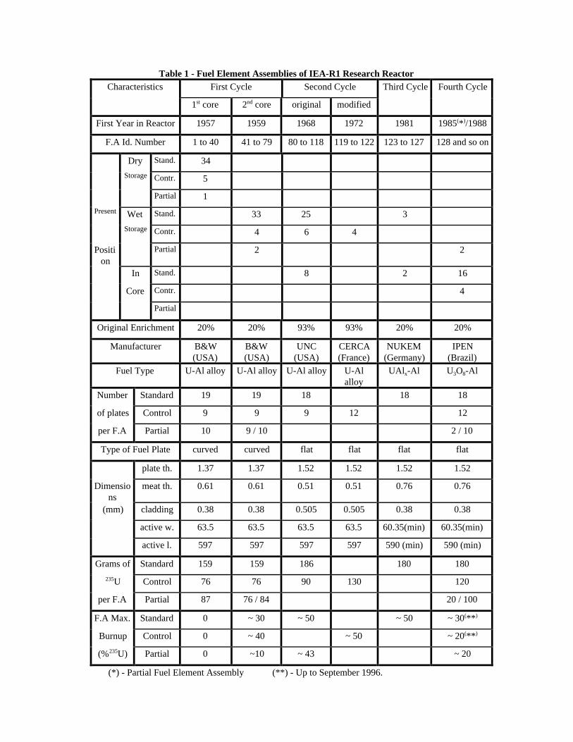
Table 1 - Fuel Element Assemblies of IEA-R1 Research ReactorCharacteristics First Cycle Second Cycle Third Cycle Fourth Cycle
1st core 2nd core original modified
First Year in Reactor 1957 1959 1968 1972 1981 1985(*)/1988
F.A Id. Number 1 to 40 41 to 79 80 to 118 119 to 122 123 to 127 128 and so on
Dry Stand. 34
Storage Contr. 5
Partial 1
Present Wet Stand. 33 25 3
Storage Contr. 4 6 4
Position
Partial 2 2
In Stand. 8 2 16
Core Contr. 4
Partial
Original Enrichment 20% 20% 93% 93% 20% 20%
Manufacturer B&W(USA)
B&W(USA)
UNC(USA)
CERCA(France)
NUKEM(Germany)
IPEN(Brazil)
Fuel Type U-Al alloy U-Al alloy U-Al alloy U-Alalloy
UAlx-Al U3O8-Al
Number Standard 19 19 18 18 18
of plates Control 9 9 9 12 12
per F.A Partial 10 9 / 10 2 / 10
Type of Fuel Plate curved curved flat flat flat flat
plate th. 1.37 1.37 1.52 1.52 1.52 1.52
Dimensions
meat th. 0.61 0.61 0.51 0.51 0.76 0.76
(mm) cladding 0.38 0.38 0.505 0.505 0.38 0.38
active w. 63.5 63.5 63.5 63.5 60.35(min) 60.35(min)
active l. 597 597 597 597 590 (min) 590 (min)
Grams of Standard 159 159 186 180 180
235U Control 76 76 90 130 120
per F.A Partial 87 76 / 84 20 / 100
F.A Max. Standard 0 ~ 30 ~ 50 ~ 50 ~ 30(**)
Burnup Control 0 ~ 40 ~ 50 ~ 20(**)
(%235U) Partial 0 ~10 ~ 43 ~ 20
(*) - Partial Fuel Element Assembly (**) - Up to September 1996.

The dry storage is located at the first floor of the reactor building and is composed byhorizontal silos at a concrete wall.
The reactor pool is divided in two sections. The first section is the core pool, wherethe core and irradiation facilities are located. The second sector is the spent fuel pool, wherethe spent fuel storage racks are laid. Figure 1 shows the rector pool with the two sections.
The spent fuel assemblies in dry storage are those of the first load (first cycle) thatpresented corrosion and fission products release at the earlier stages of reactor operation.Their burnups are almost zero, but some of them have more than 1 R/h of dose rate at the fuelassembly surface. These fuel assemblies have plastic bags wrapping them, and the discussionof canning or not them before shipment has to be done with the shipper and the receivingfacility.
The fuel assemblies in the pool are all those used up to now except the first load.Some of these spent fuels are almost 40 years inside the pool and more than 30 years insidethe spent fuel racks. Some of these fuels present pitting corrosion nodules, visible by nudeeyes, and these corrosion nodules may reach the fuel plate meat, exposing fission products tothe pool water.
Pool water radiochemistry analysis, along the various years of sampling, have beenshowing a low 137Cs activity (less than 5 Bq/l). This means that there are some leaking fuelassemblies. This activity is also low because there is a constant water cleaning system inoperation.
The pool water quality is excellent. pH is ever kept between 5.5 and 6.5, conductivityis below 2 µS/cm and chlorides are less than 0.5 ppm. Although these excellent watercharacteristics the old fuel assemblies show pitting corrosion. This is due to galvaniccorrosion because the spent fuel racks are made of stainless steel and the fuel cladding ismade of aluminum. In the 70’s the reactor pool wall was changed from ceramic to stainlesssteel liner and also the spent fuel rack was changed from aluminum alloy to stainless steel.This was done at that time not taking into account the possibility of galvanic corrosionbetween fuel assembly and storage rack.
During the next ten years, all the spent fuels of American origin have to be sent backto the USA. Last June, a US-DOE staff came to IPEN to discuss the shipment of these fuels.One of the points of discussion was the necessity of canning leaking spent fuels. Theproposal of DOE staff was to perform sipping test inside the shipping cask, with all fuelsloaded. IPEN pointed out that this wouldn’t be a good solution because if any cesium releasewere detected, all fuel assemblies would be sent back to the pool storage and an investigationwould have to be done to identify the leaking fuel assembly. IPEN proposed to performindividual sipping test of each fuel assembly before transference to the shipping cask. As theschedule for shipment was very tight, sipping tests had to be done quickly. IPEN performedvisual inspection and sipping tests in 60 spent fuel assemblies in two weeks of working, anddid the selection of the fuel assemblies that could be shipped without canning.
This work was verified, in late July, by another group from DOE-Savannah RiverSite that came to IPEN. This group agreed with IPEN methodology and results for thesipping tests. They asked for additional sipping tests to confirm the results, performed somevisual inspection of fuel assemblies using underwater camera, and also visual inspection ofsome fuels at dry storage.
This paper describes this work done by IPEN which objective was to identify the fuelassemblies that could be sent back to US, at the first shipment from South America, withoutcanning[1]. It is not presented at this paper the visual inspections performed together withDOE-SRS group.

Figure 1

VISUAL INSPECTION
The visual inspection was done by nude eyes with the fuel assembly inside the poolwith 2 meters of depth. As IPEN didn’t have any underwater camera, this visual inspectionwas done just to verify if was there any visual corrosion pit at the outer surface of outer fuelplates and the pattern of this occurrence. The inspected fuel assemblies were the LEU fuels ofthe second core, first cycle, (I.D number IEA-41 through IEA-80) and the HEU fuels of thesecond cycle (I.D number 81 through 118).
In many fuel assemblies was observed the occurrence of corrosion pits. Some patternsobserved are:
- there are corrosion pits along the interface of external fuel plate with the side plate.The pits seem to be localized at the fuel plate side. These regions normally are out of the fuelplate active width, although there is no way to confirm if the corrosion pit is deep enoughthrough the fuel plate meat;
- there are some fuel assemblies with corrosion pits along the fuel plates in definedregions of the plate where there is contact between the fuel plate surface and the spent rackframe surface;
- some fuel assemblies show corrosion pits along the height of the external fuel plate.Observing the position of these fuel assemblies in the spent fuel rack it is noticed that theyare located at corner positions in the rack where there are close contact of the fuel assemblywith the rack frame;
- LEU fuel assemblies, having curved fuel plates, show corrosion pits at the convexplates ( that have contact with the rack frame) and show very few corrosion pits at theconcave fuel plates (that have no contact with the rack frame). This is a very strong evidenceof pitting corrosion by galvanic phenomena that is occurring to the fuel assemblies;
- the lateral support plates show few corrosion pits in some fuel assemblies and mostof them in the region where exists contact with the rack frame;
- as the visual inspection did not used any equipment, it was not possible to see anycorrosion occurrence at the internal fuel plates of the fuel assemblies. The visual observationis based only on the external fuel plates.
From these visual observations it was concluded that the main reason of the pittingcorrosion existence is the galvanic pair existing between fuel assembly and support rack. Thematerial of fuel plate cladding is Al 1060, the side plate is Al 6061 T6 , and the support rackis SS AISI 304. Also there is some galvanic pair between fuel plate cladding and side plate,but this effect could be not so strong if the stainless steel rack would not be in contact withside plate or fuel plate.
Table 2 shows a resume of the visual inspection.IPEN had already some experimental results of pitting corrosion in a fresh fuel
assembly laid inside the spent fuel rack. It was observed that the external fuel plates showedcorrosion pits at points where there was contact between fuel plate and the stainless steelsupport rack frame. The side plate showed corrosion pits, at the same position of contact withthe support rack frame but with less intensity, as shown by the fuel plate (side plate made of

Al 6262 T6, and fuel plate cladding made of Al 1060). There were no corrosion pits at theinternal fuel plates.
These observations can also be applied to the spent fuel assemblies, where it wasnoticed that fuel plates have more corrosion pits than the side plates. Perhaps it is fair toconclude, as observed in the fresh fuel, that also the internal fuel plates do not have (or atleast have few) corrosion pits.
The inspection of the fuel assemblies with underwater camera was made afterwardstogether with the DOE-Savannah River Site group. The pattern of the pitting corrosionnodules, their sizes and location were investigated. Nevertheless these results andobservations will not be discussed at this paper. At this paper the emphasis will be given tothe sipping tests and the leaking pattern of the fuel assemblies.
Table 2 - Visual Inspection Resume
LEU Fuel Assemblies HEU Fuel Assemblies
Corrosion Pits along
Fuel Plates
42 43 48 49 53 55 58
61 62 64 66 69 70 78
79
103 106
Few Corrosion Pits at
Fuel Plates
41 44 45 46 47 50 51
52 54 56 57 59 60 63
65 67 68 71 72
95 97 99 100 102 104
105 109
No RemarkableObservation
73 80 81 83 84 88 91 92
93 96 98 101 107 108
111 112
SIPPING TEST
Procedure
In order to perform the sipping test, the irradiated fuel assemblies were withdrawnfrom the spent fuel storage rack, have a rigid plastic pipe connected to its bottom nozzle, andwere placed inside an aluminum sipping tube (120 mm of diameter, 3 m length, ~ 33 l ofvolume), as shown in Figure 2. This first part of the procedure was always done with the fuelassembly positioned, approximately, 2 meters of depth inside the pool water and monitoredcontinuously by the radiological protection staff. Before the tests, the sipping tube waswashed with demineralized water to reduce as much as possible any kind of residualcontamination of radionuclides (mainly 24Na).
The sipping tube with the fuel assembly inside was then lifted up and the top nozzle ofthe tube put above the surface of the water. It was then fixed to the pool bridge by a nylonrope. A total of 150 liters of demineralized water was then injected through the plastic pipeand flushed through the fuel assembly in order to wash it, as shown in Figure 2. After that, abackground sample of the tube water was collected in a small plastic bottle (100 ml) andsubmitted to gamma -ray spectrometry analysis.

The fuel assembly was then left at rest inside the sipping tube during a time interval ofat least four hours. Once finished the resting time, compressed air was injected through theplastic pipe and flushed through the fuel assembly, during two minutes, in order tohomogenize the solution that might contain fission products released by the leaking fuelassembly. A sample of this solution was collected in a small plastic bottle (100 ml) andsubmitted to gamma-ray spectrometry analysis. All bottles used for sampling were identical.Once again, the work was monitored by the radiological protection staff.
Sipping tests following this procedure were performed on 60 irradiated fuelassemblies. Five aluminum sipping tubes were used simultaneously, and all work was done intwo weeks.
A sample of pool water was also collected to serve as general gamma-ray backgroundsurvey.
Figure 2 - Scheme of Sipping
Gamma-Ray Spectrometry
The gamma-ray spectrometry analysis was carried out with a shielded ORTEC HPGedetector of volume 130 cm3 with resolution of 2,0 keV and efficiency of 25% for the 1332keV line of 60Co. The gamma-ray energy range taken for the analysis was from 50 keV to2800 keV. The data acquisition was performed with a ORTEC multichannel analyzer systemcoupled to a microcomputer through a control interface. Gamma-ray spectra were taken inruns of 4000 seconds of live time each.
The calibration of energy was obtained using a total of 40 peaks from 14 calibrationsources. Gamma-ray energies were fitted as a second degree polynomial function of thecorresponding peak channels in the calibration spectra.
Step 1- Loading the F.A into the Al Tube :
1,0 m Pool(Mín.)
2,0 m
3,0 m
F.A
F.A Handling Tool
Al Tube
Crane Operating Floor
Step 2- Sipping Sequence with the Tube Edgeout of the Pool
1,8 m
Pool
Al Tube full of water
Water Suply
0,3 m
Al Tube Fixed by a Rope
F.A
Al Tube
The calibration of efficiency for the 661.6 keV gamma-ray under fixed geometryconditions was performed using a standard solution of 1.15x10⁵ Bq of 137Cs contained in aplastic bottle identical to the ones used to collect sipping water samples. Measurements madewith this liquid calibration source gave an efficiency of ε = (8.21 ± 0.25).10-3.
For each measurement, the plastic bottle containing the collected water sample wasplaced inside the detector shield and near the detector window by means of a fixed woodsupport in order to maintain the same steady geometry for counting.
Two kinds of background measurements were carried out. The first one measured asample of demineralized water in order to determine the natural gamma-ray background. Thesecond one measured a sample of the pool water in order to determine the general gamma-raybackground. No 661.6 keV photopeak was found at all in both background spectra (seeFigures 3,4 and 5).
The 661,6 keV photopeak of each sipping spectrum, if any, was fitted by gaussianfunction plus a parabolic curve for the continuous background using the computer codeIDEFIX[2]. By means of this procedure, the net number of counts (Area) under the 661.6 keVphotopeak was determined and therefore the specific 137Cs activity A of the solution as
AArea
T I Vol=
ε γ. . . (1)
where ε is the efficiency value mentioned before, T is the live time of measurement, Iγ is thegamma-ray absolute intensity and Vol is the volume of the sipping sample.
Results
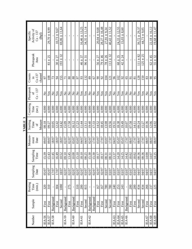
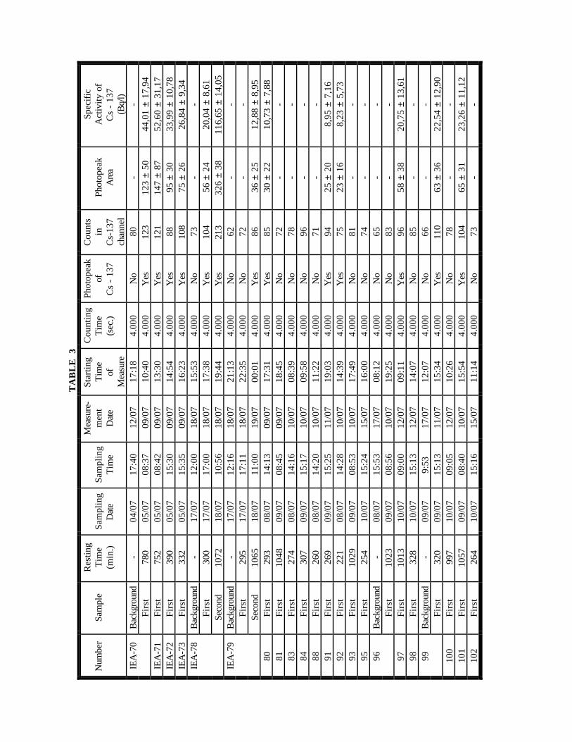
Table 3 shows the results of the gamma-ray spectra and activities of the 137Cs for thefuel assemblies sipping samples. Table 4 shows the results of the system background andFigure 3 shows the gamma spectrum for the system background. Table 5 shows the results ofthe pool water background at the region of sipping test.
Some of the items shown in Table 3 have the following meaning:i) samples. background - analysis of the gamma spectrum from the water sample taken after
water flushing through the fuel assembly and before resting time;
. first - analysis of gamma spectrum from the first water sample taken after restingtime (called short sipping ~4 hours of resting time);
. second - analysis of gamma spectrum from the second water sample taken afterresting time (called long sipping ~ > 8 hours of resting time).
ii) 137Cs photopeak. no - there is no defined photopeak at the channel related to the energy of 137Cs
gamma-ray (661.6 keV);
. counts - number of counts (for the established counting time - 4000 seconds) at thechannel related to the energy of 137Cs;
. photopeak area - calculated area for the photon peak related to the energy of 137Cs;
. specific activity - activity of the sample calculated by means of equation (1).

TA
BL
E 3
-
F U
E L
E
L E
M E
N T
S
A S
S E
M B
L I
E S
S I
P P
I N
G
Num
ber
Sam
ple
Res
ting
Tim
e(m
in.)
Sam
plin
gD
ate
Sam
plin
gT
ime
Mea
sure
-m
ent
Dat
e
Sta
rtin
gT
ime
ofM
easu
re
Cou
ntin
gT
ime
(sec
.)
Phot
opea
kof
Cs
- 13
7
Cou
nts
inC
s-13
7ch
anne
l
Phot
opea
kA
rea
Spec
ific
Act
ivit
y of
Cs
- 13
7(B
q/l)
IEA
-41
Bac
kgro
und
-02
/07
09:0
002
/07
09:1
74.
000
No
63-
-F
irst
280
02/0
713
:40
02/0
716
:20
4.00
0N
o72
--
IEA
-42
Bac
kgro
und
-02
/07
09:4
002
/07
22:1
44.
000
No
66-
-F
irst
255
02/0
713
:55
03/0
708
:20
4.00
0Y
es85
52 ±
34
18,6
1 ±
12,1
8IE
A-4
3B
ackg
roun
d-
02/0
710
:17
03/0
709
:40
4.00
0N
o63
--
Fir
st29
702
/07
15:1
403
/07
11:1
54.
000
Yes
8965
± 3
923
,26
± 13
,97
IEA
-44
Fir
st18
002
/07
18:1
403
/07
19:3
14.
000
No
79-
-Se
cond
795
03/0
708
:30
04/0
710
:19
4.00
0Y
es90
36 ±
27
12,8
8 ±
9,67
IEA
-45
Fir
st26
203
/07
13:3
204
/07
14:4
14.
000
No
83-
-IE
A-4
6F
irst
240
03/0
713
:52
04/0
718
:19
4.00
0N
o77
--
IEA
-47
Bac
kgro
und
-01
/07
12:1
601
/07
19:0
57.
200
No
135
--
Fir
st26
401
/07
16:4
001
/07
17:0
17.
200
Yes
165
149
± 52
29,6
2 ±
10,3
8IE
A-4
8F
irst
225
03/0
718
:50
05/0
708
:09
4.00
0N
o74
--
Seco
nd85
004
/07
08:3
905
/07
12:3
64.
000
Yes
9535
± 2
212
,52
± 7,
88IE
A-4
9F
irst
185
03/0
718
:05
05/0
713
:47
4.00
0N
o90
--
Seco
nd82
004
/07
08:4
005
/07
14:5
64.
000
Yes
107
62 ±
47
22,1
8 ±
16,8
3IE
A-5
0F
irst
247
04/0
714
:02
05/0
716
:19
4.00
0Y
es84
25 ±
17
8,95
± 6
,09
IEA
-51
Fir
st23
504
/07
14:2
005
/07
17:2
74.
000
No
75-
-IE
A-5
2F
irst
790
05/0
708
:35
08/0
715
:27
4.00
0N
o88
--
IEA
-53
Bac
kgr.-
1-
04/0
717
:55
09/0
712
:22
4.00
0N
o75
--
Fir
st76
505
/07
08:4
008
/07
16:4
34.
000
Yes
178
261
± 55
93,3
9 ±
19,8
8F
irst
765
05/0
708
:40
12/0
720
:02
86.4
00Y
es3.
672
5984
±171
99,1
3 ±
4,14
Bac
kgr.
-2-
10/0
716
:13
16/0
708
:45
4.00
0N
o69
--
Seco
nd10
4111
/07
09:3
416
/07
10:3
84.
000
Yes
194
422
± 32
151,
00 ±
12,
34Se
cond
1041
11/0
709
:34
23/0
715
:30
4.00
0Y
es26
138
2 ±
3013
6,69
± 1
0,74
IEA
-54
Fir
st74
005
/07
08:4
508
/07
18:0
54.
000
Yes
112
115
± 67
41,1
5 ±
24,0
1IE
A-5
5F
irst
345
05/0
715
:33
09/0
707
:02
4.00
0N
o87
--
TA
BL
E 3
Num
ber
Sam
ple
Res
ting
Tim
e(m
in.)
Sam
plin
gD
ate
Sam
plin
gT
ime
Mea
sure
-m
ent
Dat
e
Sta
rtin
gT
ime
ofM
easu
re
Cou
ntin
gT
ime
(sec
.)
Phot
opea
kof
Cs
- 13
7
Cou
nts
inC
s-13
7ch
anne
l
Phot
opea
kA
rea
Spec
ific
Act
ivit
y of
Cs
- 13
7(B
q/l)
IEA
-56
Fir
st32
005
/07
15:3
909
/07
08:1
84.
000
No
97-
-IE
A-5
7F
irst
310
05/0
715
:43
09/0
709
:27
4.00
0Y
es10
883
± 2
529
,70
± 8,
99IE
A-5
8B
ackg
roun
d-
17/0
711
:45
18/0
710
:05
4.00
0N
o73
--
Fir
st30
417
/07
16:4
918
/07
12:4
24.
000
Yes
9430
± 2
710
,73
± 9,
67Se
cond
1080
18/0
710
:52
18/0
714
:42
4.00
0Y
es15
519
3 ±
3269
,06
± 11
,64
IEA
-59
Bac
kgro
und
-02
/07
09:1
002
/07
15:0
94.
000
No
71-
-F
irst
275
02/0
713
:45
02/0
717
:58
4.00
0N
o80
--
IEA
-60
Bac
kgro
und
-02
/07
10:0
003
/07
16:1
24.
000
No
88-
-F
irst
310
02/0
715
:10
03/0
717
:23
4.00
0N
o97
--
IEA
-61
Fir
st20
002
/07
18:1
004
/07
11:4
44.
000
Yes
9346
± 3
716
,46
± 13
,25
Seco
nd81
503
/07
08:2
504
/07
13:1
14.
000
Yes
132
96 ±
31
34,3
5 ±
11,1
4IE
A-6
2B
ackg
roun
d-
02/0
715
:30
02/0
719
:40
4.00
0N
o89
--
Bac
kgro
und
-02
/07
15:3
017
/07
17:3
34.
000
No
67-
-F
irst
167
02/
0718
:17
03/0
714
:52
4.00
0Y
es90
56 ±
27
20,0
4 ±
9,68
Fir
st16
7 0
2/07
18:1
717
/07
18:4
54.
000
Yes
9279
± 4
628
,27
± 16
,48
Seco
nd78
003
/07
08:3
103
/07
13:0
84.
000
Yes
104
78 ±
26
27,9
1 ±
9,34
Seco
nd78
003
/07
08:3
117
/07
19:5
64.
000
Yes
121
113
± 32
40,4
3 ±
11,5
2IE
A-6
3F
irst
240
03/0
713
:37
04/0
719
:31
4.00
0N
o96
--
IEA
-64
Fir
st25
303
/07
14:2
005
/07
18:3
84.
000
Yes
102
68 ±
35
24,3
3 ±
12,5
5IE
A-6
5F
irst
243
03/0
714
:25
05/0
719
:49
4.00
0Y
es92
42 ±
24
15,0
3 ±
8,60
IEA
-66
Bac
kgro
und
-03
/07
14:4
217
/07
10:0
74.
000
No
65-
-F
irst
200
03/0
718
:02
08/0
707
:58
4.00
0N
o91
--
Fir
st20
003
/07
18:0
217
/07
14:1
14.
000
No
81-
-Se
cond
834
04/0
708
:36
08/0
709
:24
4.00
0Y
es12
811
1 ±
8239
,72
± 29
,37
Seco
nd83
404
/07
08:3
617
/07
15:2
74.
000
Yes
150
125
± 25
44,7
3 ±
9,05
IEA
-67
Fir
st26
604
/07
14:0
008
/07
10:3
64.
000
No
83-
-IE
A-6
8F
irst
237
04/0
714
:07
08/0
712
:06
4.00
0Y
es90
62 ±
45
22,1
8 ±
16,1
2IE
A-6
9F
irst
225
04/0
714
:25
08/0
714
:02
4.00
0Y
es95
55 ±
32
19,6
8 ±
11,4
7
TA
BL
E 3
Num
ber
Sam
ple
Res
ting
Tim
e(m
in.)
Sam
plin
gD
ate
Sam
plin
gT
ime
Mea
sure
-m
ent
Dat
e
Sta
rtin
gT
ime
ofM
easu
re
Cou
ntin
gT
ime
(sec
.)
Phot
opea
kof
Cs
- 13
7
Cou
nts
inC
s-13
7ch
anne
l
Phot
opea
kA
rea
Spec
ific
Act
ivit
y of
Cs
- 13
7(B
q/l)
IEA
-70
Bac
kgro
und
-04
/07
17:4
012
/07
17:1
84.
000
No
80-
-F
irst
780
05/0
708
:37
09/0
710
:40
4.00
0Y
es12
312
3 ±
5044
,01
± 17
,94
IEA
-71
Fir
st75
205
/07
08:4
209
/07
13:3
04.
000
Yes
121
147
± 87
52,6
0 ±
31,1
7IE
A-7
2F
irst
390
05/0
715
:30
09/0
714
:54
4.00
0Y
es88
95 ±
30
33,9
9 ±
10,7
8IE
A-7
3F
irst
332
05/0
715
:35
09/0
716
:23
4.00
0Y
es10
875
± 2
626
,84
± 9,
34IE
A-7
8B
ackg
roun
d-
17/0
712
:00
18/0
715
:53
4.00
0N
o73
--
Fir
st30
017
/07
17:0
018
/07
17:3
84.
000
Yes
104
56 ±
24
20,0
4 ±
8,61
Seco
nd10
7218
/07
10:5
618
/07
19:4
44.
000
Yes
213
326
± 38
116,
65 ±
14,
05IE
A-7
9B
ackg
roun
d-
17/0
712
:16
18/0
721
:13
4.00
0N
o62
--
Fir
st29
517
/07
17:1
118
/07
22:3
54.
000
No
72-
-Se
cond
1065
18/0
711
:00
19/0
700
:01
4.00
0Y
es86
36 ±
25
12,8
8 ±
8,95
80F
irst
293
08/0
714
:13
09/0
717
:31
4.00
0Y
es85
30 ±
22
10,7
3 ±
7,88
81F
irst
1048
09/0
708
:45
09/0
718
:45
4.00
0N
o72
--
83F
irst
274
08/0
714
:16
10/0
708
:39
4.00
0N
o78
--
84F
irst
307
09/0
715
:17
10/0
709
:58
4.00
0N
o96
--
88F
irst
260
08/0
714
:20
10/0
711
:22
4.00
0N
o71
--
91F
irst
269
09/0
715
:25
11/0
719
:03
4.00
0Y
es94
25 ±
20
8,95
± 7
,16
92F
irst
221
08/0
714
:28
10/0
714
:39
4.00
0Y
es75
23 ±
16
8,23
± 5
,73
93F
irst
1029
09/0
708
:53
10/0
717
:49
4.00
0N
o81
--
95F
irst
254
10/0
715
:24
15/0
716
:00
4.00
0N
o74
--
96B
ackg
roun
d-
08/0
715
:53
17/0
708
:12
4.00
0N
o65
--
Fir
st10
2309
/07
08:5
610
/07
19:2
54.
000
No
83-
-97
Fir
st10
1310
/07
09:0
012
/07
09:1
14.
000
Yes
9658
± 3
820
,75
± 13
,61
98F
irst
328
10/0
715
:13
12/0
714
:07
4.00
0N
o85
--
99B
ackg
roun
d-
09/0
79:
5317
/07
12:0
74.
000
No
66-
-F
irst
320
09/0
715
:13
11/0
715
:34
4.00
0Y
es11
063
± 3
622
,54
± 12
,90
100
Fir
st99
710
/07
09:0
512
/07
10:2
64.
000
No
78-
-10
1F
irst
1057
09/0
708
:40
10/0
715
:54
4.00
0Y
es10
465
± 3
123
,26
± 11
,12
102
Fir
st26
410
/07
15:1
615
/07
11:1
44.
000
No
73-
-

TA
BL
E 3
Num
ber
Sam
ple
Res
ting
Tim
e(M
in)
Sam
plin
gD
ate
Sam
plin
gT
ime
Mea
sure
-m
ent
Dat
e
Sta
rtin
gT
ime
ofM
easu
re
Cou
ntin
gT
ime
(sec
.)
Phot
opea
kof
Cs
- 13
7
Cou
nts
inC
s-13
7ch
anne
l
Phot
opea
kA
rea
Spec
ific
Act
ivit
y of
Cs
- 13
7(B
q/l)
103
Fir
st99
310
/07
09:1
512
/07
11:4
04.
000
No
91-
-10
4F
irst
1017
10/0
708
:55
11/0
723
:45
4.00
0Y
es99
28 ±
24
10,0
2 ±
8,59
105
Fir
st25
210
/07
15:2
715
/07
17:0
84.
000
No
75-
-10
6F
irst
983
10/0
709
:20
12/0
712
:59
4.00
0Y
es92
47 ±
29
16,8
2 ±
10,3
910
7F
irst
282
09/0
715
:21
11/0
716
:46
4.00
0N
o83
--
108
Fir
st24
408
/07
14:2
410
/07
13:1
04.
000
No
63-
-10
9F
irst
260
10/0
715
:20
15/0
714
:23
4.00
0Y
es85
55 ±
25
19,6
8 ±
8,96
111
Fir
st10
0709
/07
09:0
211
/07
09:1
54.
000
No
82-
-11
2F
irst
335
09/0
715
:10
11/0
710
:45
4.00
0N
o70
--
TA
BL
E 4
- B
A C
K G
R O
U N
D
M
E A
S U
R E
M E
N T
S
Num
ber
Mea
sure
men
tD
ate
Sta
rtin
gT
ime
ofM
easu
re
Cou
ntin
gT
ime
(sec
.)
Phot
opea
kof
Cs
- 13
7
Cou
nts
inC
s-13
7ch
anne
l
Spec
ific
Act
ivit
y of
Cs
- 13
7 (B
q/l)
102
/07
09:1
772
00N
o13
5-
203
/07
19:3
140
00N
o63
-
TA
BL
E 5
- I
E A
R 1
R
E A
C T
O R
P
O O
L
W A
T E
R
M E
A S
U R
E M
E N
T S
Sam
plin
gD
ate
Sam
plin
gT
ime
Mea
sure
men
tD
ate
Sta
rtin
gT
ime
ofM
easu
re
Cou
ntin
gT
ime
(sec
.)
Phot
opea
kof
Cs
- 13
7
Cou
nts
inC
s-13
7ch
anne
l
Spec
ific
Act
ivit
y of
Cs
- 13
7 (B
q/l)
11/0
719
:03
No
199
-10
/07
10:2
012
/07
18:2
94.
000
No
120
-15
/07
08:4
5N
o62
-16
/07
11:4
9N
o66
-

The following observations can be taken from the Table 3:
- some fuel assemblies show the 137Cs photopeak;
- for those fuel assemblies that two samples were taken, it is noticed that the activityincreases with sipping resting time, indicating that the fuel assembly is really leaking. It is possibleto determine a leaking rate of 137Cs from the fuel assembly. For example, for the fuel assemblynumber IEA-53 this rate is ~0.2 Bq/l.min or ~14 Bq/min;
- for some fuel assemblies the activity is very low and the associated error in the analysis isbig. For longer counting time the activity is still the same but the associated error decreases;
- there is influence of the analysis date on the measured activity. This is due to theactivation of the pool water that gives a high background level in the gamma spectrum. The sippingtests were done with the reactor in operation and the level of 24Na (half-life of 15 hours) in thewater was high enough for a high Compton background. Table 5 shows the pool waterbackground and it is observed that the number of counts at the channel related to the energy of137Cs decreases with the time of the analysis after sampling. Figure 4 and 5 show the gamma-rayspectra for the pool water, where one can see the influence of 24Na in the Compton background.
- the water volume of the sipping tube is ~33 liters. The volume of the fuel assembly is ~ 2liters, and the volume lost with the compressed air injection is of ~3 liters. So the activity for thefuel assembly sipping is obtained multiplying the specific activity by 28 liters.
Figure 6 shows the counts of the 137Cs energy channel for every fuel assembly analyzed. Itcan be seen that the background analysis for that fuel assembly with no indication of 137Cs shows abase level of counts between 60 and 85 (for 4000 sec). For those fuel assemblies that indicate the137Cs photopeak the counts are higher than 90.
Figure 7 shows the specific activity calculated for each fuel assembly sipping test. It can benoticed that some fuel assemblies show a leaking pattern, and that most of fuel assemblies havespecific activities lower than 30 Bq/l (for sipping resting time of 4 hours).
Figures 8, 9, 10, and 11 show the gamma spectra for one nonleaking fuel assembly andone leaking fuel assembly, showing also the difference in the background spectra.
The procedure used for sampling and performing gamma-ray spectra analysis used a 100ml water sample and 4000 seconds of counting time. This was done due to the high number of fuelassemblies to be analyzed and the short time for doing it. In order to evaluate the precision of thevalues obtained for the specific activities, it was taken, for some fuel assemblies, water samples of850 ml. These samples were analyzed in a gamma spectrometry system with higher efficiency thanthe one used for the sipping tests. Also the counting time was taken to 50000 seconds, which givesminor counting errors. Figure 12 shows the results of this comparison. One can observe in thisfigure that the system used in the sipping test is always overestimating the results, and giving goodresults for the specific activity higher than 20 Bq/l. For lower activities the associated deviation ishigher. Being this level of activity small, it shows that the sipping test system used is very suitablefor determining leaking fuel assemblies.

RELATION BETWEEN VISUAL INSPECTION AND SIPPING
It is interesting to correlate the visual inspection pattern with the sipping results. Table 6shows this relation. One can observe that the older LEU fuel assemblies are in worse conditionthan the HEU fuel assemblies, and only few fuel assemblies have higher indication of 137Csleaking.
Table 6 - Correlation between Visual Inspection and Sipping Activityfor IEA-R1 Fuel Assemblies
Pits along externalfuel plate
Few pits alongexternal fuel plate
No visibleremarks
No Indication of
55 41, 45, 46, 51, 52, 56, 59,60, 63, 67
Cs-137103 95, 100, 102, 105 81, 83, 84, 88, 93,
96, 98, 107, ,108,111, 112
Low Indication ofCs-137
42, 43, 48, 49, 62, 64, 66,69, 79
44, 47, 50, 57, 65, 68 73
(< 30Bq/l)106 97, 99, 104, 109 80, 91, 92, 101
Medium Indicationof Cs-137
61, 70 54, 71, 72
(> 30 Bq/l;< 60Bq/l)
High Indication ofCs-137
53, 58, 78
(> 60 Bq/l)
CHEMICAL ANALYSIS
The sipping water sample, for the fuel assembly with highest leaking activity, was alsoanalyzed by X-ray fluorescence spectrometry to see whether there was Cs and U. Table 7 showsthe results. One can see that the only elements observed are those of corrosion ions from aluminumand stainless steel that are inside the pool. Cs and U were not observed. This is easy to understandif one observe the activity of 137Cs in the sipping water. For the value of 100 Bq/l represents~3x10-11 g Cs/l. This value is too small to be detect by chemical analysis. U was detected neitherby gamma ray spectrometry analysis nor by X-ray spectrometry.

Table 7 - Chemical Analysis Results (X-Ray Spectrometry)Element Fuel Assembly - EC IEA-
49Fuel Assembly - EC IEA-
53Al < 100 mg/ml < 100 mg/mlSi < 100 mg/ml < 100 mg/mlP < 100 mg/ml < 100 mg/mlS < 100 mg/ml < 100 mg/mlCa < 100 mg/ml < 100 mg/mlCr < 100 mg/ml < 100 mg/mlFe < 100 mg/ml < 100 mg/mlNi < 100 mg/ml < 100 mg/mlZn < 100 mg/ml < 100 mg/mlCo ND NDCs ND NDU ND NDIn ND NDAg ND NDCu < 100 mg/ml < 100 mg/ml
ND - Not Detected
DETERMINATION OF 137Cs LEAKING RATE
The DOE-Savannah River Site group came to IPEN to the assessment of the fuelassemblies for shipment. This group agreed with the methodology used by IPEN in performingsipping tests and also with the results obtained. Nevertheless, some additional work concerningfuel assessment was done. One task was to remove some of the external fuel plate pitting corrosionnodules of some fuel assemblies and to repeat the sipping test on these fuel assemblies. The secondtask was to determine the 137Cs leaking rate, after cleaning some pitting corrosion nodules, fromfuel assembly IEA-53 the one that showed the highest sipping activity among all fuel assemblies.Both tasks were done with IPEN methodology and equipment.
Table 8 shows the results for the specific activity in the sipping tests performed with somefuel assemblies after cleaning the outside plate surface and taking out some pitting corrosionnodules. One can observe at Table 8 that there is no evident difference between the results beforeand after cleaning. The differences are more evident upon the sipping resting time.
One can also observe at Table 8 the results for fuel assembly IEA-53. Figure 13 shows theactivity along sipping resting time. The results show a straight line with a constant leaking rate of~0.2 Bq/l.min or ~14 Bq/min. Figure 14 compares the rate before and after cleaning and one cansee that there is almost no difference.
Being the fuel assembly IEA-53 the one which had the highest leaking rate, this value of 14Bq/min can be compared to the criteria established by DOE-SRS for canning leaking fuelassemblies.
The DOE-SRS interim criteria presented to IPEN was 13.57 µCi/hr per cask shipmentwhich is equivalent to 35.9 pCi/ml.hr for one fuel assembly (assuming 3.6 gallons of water pereach fuel assembly).
The value obtained at IPEN fuel assembly sipping, correcting to the volume of SRScriteria, is 0.64 pCi/ml.hr (0.4 Bq/l.min.) which is far bellow the criteria limit.

TA
BL
E 8
- F
U E
L
E L
E M
E N
T S
A
S S
E M
B L
I E
S
S I
P P
I N
G
B E
F O
R E
C
L E
A N
I N
GA
F T
E R
C
L E
A N
I N
G
Num
ber
Sam
ple
Res
tT
ime
(Min
)
Phot
opea
kof
Cs
- 13
7
Cou
nts
inC
s-13
7ch
anne
l
Phot
opea
kA
rea
Spec
ific
Act
ivit
y of
Cs
- 13
7(B
q/l)
Res
tT
ime
(Min
)
Phot
opea
kof
Cs
- 13
7
Cou
nts
inC
s-13
7ch
anne
l
Phot
opea
kA
rea
Spec
ific
Act
ivit
y of
Cs
- 13
7(B
q/l)
IEA
-41
Fir
st28
0N
o72
--
240
No
82-
-IE
A-4
5F
irst
262
No
83-
-24
0N
o68
--
IEA
-53
Bac
kgro
und
-N
o75
--
-N
o68
--
Fir
st76
5Y
es17
826
1 ±
5593
,39
± 19
,88
275
Yes
147
119
± 29
42,5
8 ±
10,4
6Se
cond
1041
Yes
228
401
± 2
214
2,86
± 8
,10
1370
Yes
418
740
± 39
264,
79 ±
16,
12T
hird
--
--
-17
70Y
es52
598
8 ±
4335
3,53
±
18,7
8F
orth
--
--
-27
30Y
es77
815
17 ±
47
542,
82 ±
23,
58F
ifth
--
--
-31
27Y
es77
317
37 ±
56
621,
54 ±
27,
56IE
A-7
3F
irst
332
Yes
108
75 ±
26
26,8
4 ±
9,34
240
No
77-
-92
Fir
st22
1Y
es75
23 ±
16
8,23
± 5
,73
240
No
77-
-93
Fir
st10
29N
o81
--
315
No
75-
-97
Fir
st10
13Y
es96
58 ±
38
20,7
5 ±
13,6
124
0N
o70
--
101
Fir
st10
57Y
es10
465
± 3
123
,26
± 11
,12
240
No
75-
-10
3F
irst
993
No
91-
-24
0Y
es89
27 ±
19
9,66
± 6
,80
104
Fir
st10
17Y
es99
28 ±
24
10,0
2 ±
8,59
240
No
83-
-10
6F
irst
983
Yes
9247
± 2
916
,82
± 10
,39
255
No
72-
-

Nevertheless DOE interpretation of Foreign Research Reactor Environmental ImpactStatement (FRR.EIS) says that any fuel that contain a thru-clad pit may require canning forshipment and storage. So, although the sipping criteria is fulfilled by IPEN fuel assemblies, DOEimposes some restraint upon corrosion pattern. It is the authors concern, that this subject has to bediscussed in more details in order to have a well established criteria, since any detected 137Cssipping activity would be a consequence of a thru-clad pit.
GAMMA-RAY SPECTROMETRY OF A PITTING CORROSION NODULE
A sample of a pitting corrosion nodule of a fuel plate was taken to perform gamma-rayspectrometry analysis. Figure 15 shows the gamma-ray spectrum obtained. One can find a largeactivity of 137Cs and also activities of 235U, 155Eu, and 154Eu. This indicates that the pittingcorrosion nodule penetrates through the cladding up to the plate meat where there is uranium andfission products. Also indicates that besides 137Cs, U and Eu isotopes are migrating from the meatto the nodule. U and Eu are not migrating (or migrating in a very small rate) to the water, thoughthis elements were not found in the gamma-ray spectrometry of the sipping water. This mechanismof U and F.P. migration from the plate meat through the corrosion pit to water(migration/solubility/diffusion/chemical compounds/chemical reaction/etc.) has to be more deeplystudied.
The activity of 137Cs in the pitting corrosion nodule sample was determinate to be 2400 Bqor 5600 Bq/g. It is interesting to compare this activity with the meat activity and the sipping wateractivity.
The 137Cs plate activity, obtained by the code ORIGEN2[3] , taking into consideration theplate burnup and decay time to the date of the sipping test, is ~ 2Ci or 7.4x10¹⁰ Bq. Consideringthe weight and volume of the U-Al alloy of the plate meat, the specific activity is given by 3.4x10⁹
Bq/cm3 or 7.5x10⁸ Bq/g(U-Al).So, the three values of 137Cs activities are:
- meat - 7.5x10⁸ Bq/g ;or ~ 7.4x10¹⁰ Bq/plate ; or ~1.3x10¹² Bq/F.A
- corrosion pit nodule - 5.6x10³ Bq/g ; or ~ 2.4x10³ Bq/nodule
- sipping water sample - 14 Bq/min ; or 0.2 Bq/l.min ; or 2x10⁻⁵ Bq/g.min (max. per fuel assembly)
There is a migration of 137Cs from the meat to the water, with a retention at the pittingcorrosion nodule, with a leaking rate of orders of magnitude below the meat activity.
CONCLUSION
The visual inspection of the spent fuel assemblies storage at the spent fuel pool showed that pittingcorrosion is present in the external fuel plates of many fuel assemblies. Those which are insidewater for almost 40 years show the worst pattern. The pitting corrosion observed is due to thegalvanic pair existing between aluminum fuel plate cladding and the stainless steel spent fuel rack. • The sipping test methodology and equipment used by IPEN showed to be efficient in
determining fission products leaking fuel assemblies.
• It was determined a 137Cs leaking rate of 14 Bq/min for the worst leaking fuel assembly. Thisvalue is far bellow the DOE-SRS criteria presented to IPEN for canning leaking MTR fuelassemblies.
• Pitting corrosion nodule gamma-ray spectrometry shows the occurrence of Cs, U and Eu
isotopes. The 137Cs activity is much higher than the sipping water activity and U and Euisotopes were not detected in water. This confirms that it is a thru-clad pit.
The following items are suggested, by the authors, for future research.
• Increase the understanding of galvanic pitting corrosion between Al alloys and stainless steel inthe basin. Also the difference of the pit pattern for different types of MTR fuel plates (U-Alalloy and dispersion fuels- U3O8-Al, U3Si2-Al, UAlx-Al).
• Increase the understanding of the phenomena involved in the U and fission products migration
through a pitting corrosion nodule to the basin. Also the difference of these phenomena fordifferent types of MTR fuel plates.
• Discuss the visual thru-clad pit criteria for canning leaking fuel assemblies for shipment andstorage.
ACKNOWLEDGMENTS
The authors would like to demonstrate their gratitude to H.Pasqualeto and R.Frajndlich, ofthe Department of Reactors Operation of IPEN/CNEN-SP, who gave the best of their personalefforts for performing the visual and sipping tests of the fuel assemblies of IEA-R1 Reactor.
It is also important to point out the good relationship between IPEN/CNEN-SP and DOE-SRS staffs during the IEA-R1 fuel assemblies assessment for shipment. The authors would like toexpress their thanks to B.K.Chambers, J.P.Howell, R.L.Sindelar, S.D.Burke, A.S.Busby, andH.B.Peacock for the participation and discussions to achieve the goals of this work.
Finally the authors would like to thank the IAEA for supporting the presentation of thiswork at this TCM in Budapest, Hungary, and particularly to thank Dr Iain Ritchie of IAEADivision of Nuclear Fuel Cycle and Waste Management.

REFERENCES
[1] Perrotta,J.A; Terremoto,L.A.A; Zeitune,C.A. “Sipping dos Elementos Combustíveis do ReatorIEA-R1” - IPEN/CNEN-SP Internal Report - PSI.REN.IEAR1.006 - (Agosto/1996).
[2] Graffon,P. “User’s Manual of Code IDEFIX” - Laboratório do Acelerador Linear, IFUSP(1983)
[3] RSIC Computer Code Collection - “ORIGEN2 - Isotope Generation and Depletion Code -Matrix Exponential Method” - RSIC Code Package CCC-371 (April 1987).