Embed Size (px)
Citation preview

I METRIC 1MIL-C-89038
1994
MILITARY SPECIFICATION
Compressed ARC Digitized Raster Graphics (CADRG )
This specification is approved for use by all
Departments and Agencie8 of the Department of Defense.
1. SCOPE
1.1 -. This specification provides requirements for thepreparation and use of the Raster Product Format (RPF) CompressedARC Digitized Raster Graphics (CADRG) data. CADRG is a generalpurpose product, comprising computer-readable digital map andchart images. It supports various weapons, C31 theater battlemanagement, mission planning, and digital moving map systems.CADRG data is derived directly from ADRG and other digital sourcesthrough downsampling, filtering, compression, and reformattingthe RPF Standard. CADRG files are physically formatted withinNational Imagery Transmission Format (NITF) message.
1.2 ~. The purpose of this document is to specify
toa
thedata format and characteristics of CADRG for producers and users.
1.3 .
1.3.1 Sectitv, ,
c~ion of ~ec~~c~, .
. Thisproduct specification is UNCLASSIFIED.
1.3.2, ,
}ecultv c~lcdtlon of Dro@ . Media containingCADRG data shall carry the highest classification and restrictionsthat are determined from the original source graphics.
Beneficial comments (recommendations, additions, deletions) andany pertinent data which may be of use in improving this doc~~t
should be addressed to: Director, Defense Mapping Agency, ATTN: PRET A-13, 8613 Lee Highway, Fairfax, VA 22031-2137 by using theStandardization Document Improvement Proposal (DD ~OrM 1426)appearing at the end of this document or by letter.
AMSC N/A AREA MCGT
DISTRIBUTION STATEMENT A. Approved for public release;distribution is unlimited.

MIL-c-89038
2. APPLICABLE DOCUMENTS
2.1.1 SDectilcaFiQnst,,
~t.~jc)o ~ Thefollowing specifications, standards,
.and handbooks form a part of
this document to the extent specified herein. Unless otherwisespecified, the issues of these documents are those listed in thecurrent Department of Defense Index of Specifications andStandards (DODISS) and the supplement thereto, cited in thesolicitation (see 6.2) .
SPECIFICATIONS
MILITARY
MIL-A-89007 – Defense Mapping Agency, Milita~Specification: ARC Digitized Raster Graphics
STANDARDS
MILITARY
MIL-STD-2411 – Defense Mapping Agency, Milita~Standard, Raster product Format (RPF)
MIL-STD-2411-1 – Defense Mapping Agency, MilitaryStandard, Registered Data Values for Raster productFormat
MIL-STD-2411-2 - Defense Mapping Agency, MilitaryStandard, Integration of Raster product FormatFiles Into the National Imagery Transmission Format
MIL-STD-2500 – Military Standard, National ImageryTransmission Format (Version 2.0)
MIL-STD-6OOO1O – Department of Defense, DMA StockNumber Bar Coding
MIL-sTD-129 – Marking for Shipment and Storage
HANDBOOKS
MILITARY
MIL-HDBK-1300 – Military Handbook, National ImageryTransmission Format Standard (NITFS)
(Unless otherwise indicated, copies of federal and militaryspecifications, standards, and handbooks are available from theStandardization Documents Order Desk, Bldg. 4D, 700 RobbinsAvenue, Philadelphia, PA 19111-5094. )
2

MIL-C-89038
2.1.2.{
er G~t i * a~. The following other Government documents, drawings,
and publications form a part of this document to the extentspecified herein. Unless otherwise specified, the issues arethose cited in the solicitation.
a. DMA Technical Manual, DMA TM 8358.1, Defense MappingAgency: Datums, Ellipsoids, Grids, and Grid Reference Systems,First Edition.
b. DMA Technical Report, DMA TR 8350.2: World GeodeticSystem 84, 2d Edition.
c. DMA Technical Instruction, TI/2DJ/001, DMA TechnicalInstructions and Quality Requirements for Printing and Finishingof Jewel Case Liners & Information Booklets (Inserts) for Mapping,Charting and Geodetic (MC&G) Compact Disk Storage Media.
(Application for DMA TR, TM, and TI copies should be addressed toDefense Mapping Agency, ATTN: AM, ST A-2, 8613 Lee Hiqhwav,Fairfax, VA 22031-2137 ‘
d. STANAG 2211,References .
e. FAR, Federal
.)
Geoid Datums, Spheroids, Grids, and
Acquisition Regulation
.
Cell
(Copies of federal and military specifications, standards, andhandbooks are available from the Standardization Documents orderDesk, Bldg. 4D, 700 Robbins Avenue, Philadelphia, PA 19111-5094. )
f. Map Pro_jections-A Working Manual, U.S. Geological SurveyProfessional Paper 1395, First Edition, 1987
(Application for copies of USGS documents should be made to U.S.Geological Survey, 507 National Center, Reston, VA 22092.)
I
2.2 ~-Gover_t’D@~lcati~~ .. The following documents
form a part of this document to the extent specified herein.Unless otherwise specified, the issues of the documents which areDOD adopted are the most current issues listed in the DODISS.Unless otherwise specified, the issues of the following documentsthat areas cited
a.Floating
b.Computer
—not listed in the DODISS are the issues of the documentsbelow.
AIWI/IEEE Std. 754-1985, IEEE Standard for BinarvPoint Arithmetic.
ANSI/IEEE 1003.1, PortableEnvironments (POSIX)
.
Operating Syst6m Interface for
3
—
MIL-C-89038
c. ISO/IEC DIS 10777-1990, 4 mm -Cartridge for Information Interchange.
d. ISO/IEC DIS 11319-1991, 8 mm -Cartridge for Information Interchange.
Wide Magnetic Tape
Wide Magnetic Tape
e. 1S0 9660-1988, Information Processing - Volume and FileStructure of CD-ROM for Information Interchange.
f. ISO/IEC DIS 10089, 130 mm Read-Writeable Optical MediaCartridge, Erasable Optical Disk (EOD)
9. ISO/IEC DIS 10139, Information Technology – DataInterchange on Read-Only 120 mm Optical Data Disks (CD-ROM)
h. ISO/IEC DIS 13346, Volume and File Structure of Write-Once and Rewriteable Media Using Nonsequential Recording (NSR) forInformation Interchange
(Application for ANSI and 1S0 copies should be addressed to theAmerican National Standards Institute (ANSI) Inc., 1430 Broadway,New York, NY. 10018.)
i. Southard, D. A., 1992, “Compression of Digitized MapImages, “ Computers and Geosciences, Vol. 18, No. 9, pp.
1213-1253.
h Markuson, N. J., July 1994, “Analysis of CompressionTechniques for Common Mapping Standard (CMS) Raster Data,”
ESCTechnical Report, MTR-93BOOOO091.
(Application for MITRE Report copies should be addressed to TheMITRE Corporation, 202 Burlington Road, Bedford, MA 01730-1420.)
2.3 der of Rrec~- . In the event of a conflict betweenthe text of this document and the references cited herein (exceptfor related associated detail specifications, specificationsheets, or MS standards) the text of this document takesprecedence. Nothing in this document, however, supersedesapplicable laws and regulations unless a specific exemption hasbeen obtained.
3. REQUIREMENTS
3.1 ~ . When specified (see 6.2), a sample shallbe subjected to first article inspection (see 6.3) in accordancewith 4.3.
3.2.1 ~ccurac~ r. Vertical accuracy is the same as that ofthe original source (paper) graphics.
4
v lJ

MIL-c-89038
u
a. The accuracy of CADRG is dependent upon the accuracy ofthe original map or chart from which source data for CADRG wasderived. The quant~.zation error attributable to downsampling from100 microns (~) in ADRG to 150 p in CADRG, contributes only aninsignificant error compared with the error inherent in theoriginal source graphics.
b. The source ADRG data originate in or have been convertedto the World Geodetic System 1984 (WGS-84) datum (see 3.3.2). Ifan ADRG image was converted to wGS-84 from another datum, then thelatitude and longitude depicted on the ADRG images (andcorresponding CADRG images) will generally no longer align withthe latitude and longitude that the gridlines represent.
3.2.3 ~tric f~it.y. The red, green, and blue (RGB)pixels of the CADRG are representations of the colors in thesource map or chart product. Color differences among maps andcharts are not removed in the process of scanning the charts. Thetransformation process for CA.DRG emphasizes image contrast,clarity and legibility over exact color fidelity; most of thecolor loss should not be operationally significant. The abilityof output systems (e.g., printers and displays) to faithfullyreproduce colors from CADRG data depends on the resolution andcolor integrity of the output systems.
3.3 pat~.
3.3.1 Yertical dam . The vertical datum for CADRG is thesame as the vertical datum of the source ADRG data and its sourcegraphics.
3.3.2 ~rizontal datu~ . The horizontal datum for CADRGshall be wGS-84, as defined by DMA TM 8358.1.
3.4 product descrfiti~ . The CADRG product shall conform toMIL-STD-2411. It normally will be produced directly from sourcemaps of all scales by processing (see 3.10) and reformatting intoa CADRG frame file structure (see 3.12) . Miscellaneous scale mapsand charts or non-DMA maps may be the source for CADRG production.The processing includes spatial reduction (pixel downsampling)with filtering, vector quantization image compression, and colorquantization.
To permit direct use by aircraft cockpit displays, CADRG data isarranged in frames and subframes with constant pixel sizes, andoverlaps (see 3.5.4) that are consistent with limited memory andprocessing capabilities of avionics computers.
5
w m w u k rl
MIL-c-89038
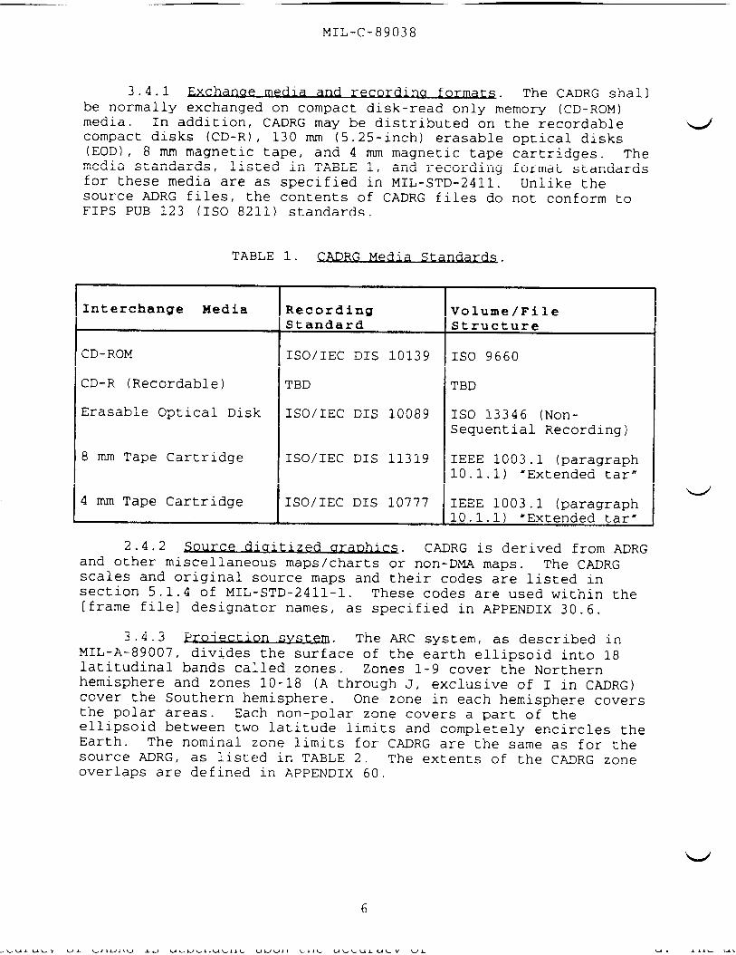
3.4.1 recor~u for- . The CADRG shallbe normally exchanged on compact disk-read only memory (CD-ROM)media. In addition, CADRG may be distributed on the recordablecompact disks (CD-R) , 130 mm (5.25-inch) erasable(EOD) , 8 mm magnetic tape, and 4 mm magnetic tapemedia standards, listed in TABLE 1, and recordingfor these media are as specified in MIL-sTD-2411.source ADRG files, the contents of CADRG files doFIPS PUB 123 (1S0 8211) standards.
optical diskscartridges . Theformat standardsUnlike the
not conform to
Interchange Media Recording Volume/FileStandard Structure
CD-ROM ISO/IEC DIS 10139 ISO 9660
CD-R (Recordable) TBD TBD
Erasable Optical Disk ISO/IEC DIS 10089 1S0 13346 (Non-Sequential Recording)
8 mm Tape Cartridge ISO/IEC DIS 11319 IEEE 1003.1 (paragraph10.1.1) “Extended tar”
4 mm Tape Cartridge ISO/IEC DIS 10777 IEEE 1003.1 (paragraph10.1.1) ‘Extended tar”
2.4.2 ce a~cs . CADRG is derived from ADRGand other miscellaneous maps/charts or non-DM.A maps. The CADRGscales and original source maps and their codes are listed in
— .section 5.1.4 of MIL-STD-2411-1. These codes are used within the[frame file] designator names, as specified in APPENDIX 30.6.
3.4.3 proiect~n ,vst~ . The ARC system, as described inMIL-A-89007, divides the surface of the earth ellipsoid into 18latitudinal bands called zones. Zones 1-9 cover the Northernhemisphere and zones 10-18 (A through J, exclusive of I in CADRG)cover the Southern hemisphere. One zone in each hemisphere coversthe polar areas. Each non-polar zone covers a part of theellipsoid between two latitude limits and completely encircles theEarth. The nominal zone limits for CADRG are the same as for thesource ADRG, as listed in TABLE 2. The extents of the CADRG zoneoverlaps are defined in APPENDIX 60.
‘w
6
[:+ , ,=

MIL-C-89038
1
TABLE 2. CADRG Zone Limits.
T
‘Zone Equatorwa-rd- Midpoint PolewardNumber Latitude Latitude Latitude
l,A 0° 22.94791772° 32°2,B 32° 41.12682127° 48°
3,C 48° 52.28859923° 56°4,D 56° 60.32378942° 64°
5,E 64° 66.09421768° 68°6,F 68° 70.10896259° 72°7,G 72° 74.13230145° 76°8,H 76° 78.17283750° 80°9,J 80° 90°
3.4.4 Qistrtition fr- . The CADRG database is composedof rectangular grids of frames of pixels for each zone. CADRG canbe distributed ‘in rectangular or non-rectangular areas, and withcontiguous or non-contiguous coverage (i.e., areas separated bylarge expanses of water, or multiple discrete maps for which nocontiguous maps exist) . Each frame is represented by a discretefile. The CA.DRG library is seamless; that is, the edges ofcontiguous source maps are indistinguishable, except by colorvariations that are due to the differences between the colors orpatterns in original source graphics. The raster graphic datafrom each (sub)frame abuts the data of neighboring (sub) framesexactly to provide unbroken coverage. Gaps in coverage existwhere the source coverage does not exist. The boundaries of thedistribution frames (see 3.5) are not required to coincide withthe source map edges.
3.4.5 . CADRG data files are arrangedin a hierarchical directory/subdirectory structure (see FIGURE 1) .The CADRG directories and data files, enumerated below, are fullydescribed in paragraphs 3.11 through 3.12. All names and labels,and the format and structure of directories shall adhere to theconventions specified in MIL-STD-2411. Any computer system thatcan access distribution media conforming to the standards listedin TABLE 1 should be able to access CADRG data.
a. Root Directory: Contains [table of contents file]or more directories of [frame file]s, a [legend directory],one or more [overview image]s. The root directo~ shall beIIRPFI,.
, oneandnamed
“’’.4’
LLl ——h— “n
7
---

MIL-C-89038
[rpf root directory] (unordered){1} (unordered)[table of contents file][overview image] (1, ... many)[legend directory] (O, 1)
{2)[legend file] (1, ... many)
{1} (unordered)[frame directory] (O, ... many)
{2) (unordered)[frame file] (O, .. many)[subordinate directory] (O, ... many) (unordered)
{31[frame file] (O, ... many)
FIGURE la. e &truct~ .
I RPF Directory II f \ (Optional)
A%%%,][frame { \
directory]ssub-level
[framedirectory]\ J
I&
w T[overview
v -[frame fiie]s
more ...-image]s - [frame file]s
)1
.[
*4
1 4
FIGURE lb. Pictorial Representation of CADRG Directory and FileStructure
b. [table of contents file]: The [table of contents file)provides an overview of the data contents of the distributionmedia. The [frame file index section] within the [table ofcontents file] provides path names to each of the [frame file]s onthe interchange volume. The path names to the [frame file]s will
8
L, , . ,-, w w 1 1 nfi -7 ‘ t mnw

MIL-C-89038
be used by user applications software to locate the [frame file]s,rather than assume any particular names or directory structure.
‘u
‘L/’
c. [frame file directory]s: CADRG producers will choose thenumber of [-frame file directory)s in a given volume and conventionfor assigning [frame file]s to directories. Each [frame filedirectory] on a given interchange volume shall be uniquelynamed in a manner to be determined by an authorized producer. Theproducers may also assign nested [frame file directory]s as neededto organize the [frame file]s, using a variable hierarchy.
d. [frame file]s: The [frame file]s contain the tiled imageand support data for the geographic frames on a CADRG interchangevolume. Each [frame file] (see 3.12) shall include a [headersection] , [location section], [coverage section], [compressionsection] , [color/grayScale section], [image section], [attributesection] (optional), [related image section] (optional), and[replace/update section] (only present for replacements andupdates) . The [frame file] naming convention shall be inaccordance with MIL-STD-2411, and is described in section 30.6 ofthe APPENDIX.
e. [legend file](s): The [legend file] (s) contain(s) thetiled image data which represent the legend information from theoriginal map series. Only one [legend file] is provided per mapseries; however, there are provisions for multiple [legend filelsper distribution volume. Each [legend file] (see 3.11.2) shallinclude a [header section] , [location section] , [compressionsection] , [color/grayscale section], [image section], and[replace/update section] (only present for replacements andupdates) . [legend file]s shall be located within the [legenddirectory] which shall be named “RPF/LEGEND.” .
f. [overview image] (s): One or more [overview image]s willbe provided per CADRG interchange media. These indicategraphically where the [frame file)s are located with respect topolitical and ocean boundaries, similar to the Location Diagram(see 5.1.2) on the jewel-box liner. [overview imagels will belocated at the same level on the media as the [table of contentsfile] . Each [overview image] (see 3.11.3) shall. include a [headersection] , [location section], [compression section],[color/grayscale section], and [image section].
3.4.6 ~. Data recording shall adhere to theconventions for logical data recording formats as specified insection 4.4 of MIL-sTD-2411. CADRG files shall be integrated withthe NITF message format in accordance with MIL-STD-2411-2.
3.5.1 pjx~l snac~ . The original source graphics for ADRGdata (from which CADRG are derived) are scanned at a 100 micron(H) pixel resolution (254 pixels per inch) in both East-West and
9

MIL-C-89038
North-South directions, and then warped from the datum of theoriginal paper map or chart to the ARC projection using the WGS-84ellipsoid. To produce CADRG, ADRG source data shall be spatiallyreduced (see 3.10.2) from the ADRG pixel spacing to a 150 ~ pixelspacing (169 pixels per inch) . For each map or chart scale, aconstant latitudinal (row) and longitudinal (column) pixelinterval shall exist in each zone, as defined in section 60 of theAPPENDIX. The numbers of CADRG pixels in the longitudinaldirection shall be adjusted so that there are integral numbers ofsubframes per zone. In the polar zone, the number of CADRG pixelsis adjusted so that there is an even number of subframes acrossthe zone in each dimension.
3.5.2 t-, ,
e .
Each frame shall comprise a rectangular array of 1536 by1536 ~~xels (2,359,296 pixels). Each frame shall be tiled into agrid of 6 by 6 subframes (36 subframes) Each subframe shallcomprise a rectangular array of 256 by 256 output pixels (65,536pixels) . Subframes shall be numbered as depicted in FIGURE 2, inaccordance with MIL-STD-2411.
b. All frames and subframes within a zone shall abut in amutually exclusive manner without any pixel overlap or pixelredundancy. The northern and southern boundaries of a zonegenerally will not fall exactly on the northern and southernboundaries of a frame or subframe. There shall be frame overlapbetween the zones, as defined in section 3.5.4.
c. For several scales of source product, APPENDIX 60 liststhe number of frame and subframe rows and columns in each zone forthe latitudinal and longitudinal directions, East-West pixelspacing constants (i.e., the number of pixels for 360° longitude),North-South pixel spacing constants (i.e., number of pixels in 90°from equator to pole), longitudinal pixel sizes (meters) for eachzone, and the latitudinal pixel sizes (meters) .
d
‘d’
d. The midpoint latitude for each zone shall be the same asfor the ADRG source product (see 3.4.3).
w“
10

MIL-c-89038
‘u’
256 Pixols”
# ‘o 1 2 3 4 5
,t6 7 1536 Pi%olc
L
Subframos 14
18 21
24 28
30 31 32 33 34 35, ‘; I
256 PiXOIO ~
CADRCJ Pram.
(6 X 6 9ubfruno Tiles)
FIGURE 2. ~.
3.5.3 .
The numbering convention for entities that are internalto th~” [frame file]s shall conform to MIL-sTD-2411. All indexnumbers shall start from O. Rows and columns of subframes in aframe, pixels, and indices in [frame file] subentities shall becounted from O. The origin for the subframe and pixel numberingwithin frames and subframes shall be from the upper left corner.Subframes and pixels shall be counted in row-major order from theorigin. Section 30 of the APPENDIX provides a set of coordinateconversions between pixel rows and columns within frames, and thelatitude and longitude of a point within a frame based upon thecoordinate information provided within the [coverage section] ofeach [frame file] .
b. In addition, CADRG frames may be considered to formconceptual “rows” and “columns” within zones. Section 30.6 of theAPPENDIX uses this concept to define the naming convention offrames for various scales by using the scale and zone specific“frame number. ” The rows and columns are numbered from O. Theorigin for counting non-polar frame rows and columns in both thenorthern and southern hemispheres is the southernmost latitude ofthe zone, and 180° west longitude, with columns counted in aneasterly direction from that origin. The origin for countingpolar frames (see 3.5.5) is the lower-left corner of the polarzone, with rows and columns numbered from that origin. Section 30of the APPENDIX provides the coordinate conversions for pointswithin a frame file.
L’
11

MIL-C-89038
a. The longitudinal and latitudinal extents of the zones inthe southern hemisphere are identical to those in the northernhemisphere.
b. Rows of frames from different zones do not have the samelongitudinal extent since the longitudinal pixel intervals differ.
c. For each non-polar zone N, the top-most frame row of thatzone corresponds in latitude with the bottom-most frame row ofzone N+l (as depicted in FIGURE 3) . Thus the frames at the topand bottom rows of each zone shall overlap frames of those zonesabove and below. The zone overlap shall be a full frame.
3.5.5 and %~fr~ s~rt~~e for DO- . TheCADRG frame and subframe structure is unique in the polar regions,in conjunction with the source products. CADRG shall use a polarstereographic projection, in which meridians (constant longitude)are plotted as radii emanating from the poles, and parallels(constant latitude) are plotted as concentric circles that arecentered at the poles.
a. The north and south polar zones, 9 and J, are depicted inFIGURE 4 and FIGURE 5, respectively. These zones are circularwith the pole at the center and the radius being the distance fromthe pole to 80° (north or south) latitude. The polar framestructure is square. The center frame is positioned with the polein the exact center of that frame and the sides of the framemaking right angles with the 0°, 90°E, 180”w, and 90°W meridians.The origin for polar zone frame rows and columns (see 3.5.3.b) isthe lower-left corner of the zone. Polar CADRG frames are not alloriented along the north-south and east-west directions. Furtherdetail on the frame structure and orientation is provided insection 60 of the APPENDIX.
b. The pixel coordinate system for polar zones is centeredat the pole. Polar zone pixels are transformed from (<X>, <Y>)
pixel row and column coordinates to latitude and longitude ($, k)
coordinates, as described in section 30 of the APPENDIX. Pixelresolutions and sizes are not constant in a left-right or up-downdirection. The number of pixels in the polar zone is adjusted sothat there are an even number of subframes centered about thepoles. There are an odd number of frames with symmet~ about thepole. APPENDIX 60 provides calculations to compute average framepixel resolution.
12

MIL-c-89038
\ :’-1
Zone rJ+l
t
Frame
Row 1
Zone N+l
Nominal
Zone Bottom two frameBoundary Frame Frame rows in Zone N+l
I
Row x Row O
Zone N Zone N+l
I *
Zone NFr<.me Top two frame
4Row x-1 rows in Zone Ii
Zon ? N
FIGURE 3. CADRG Zone Boundary Overlap Structure
3.5.6 Polar zone overla~. polar zone overlap is limited bythe source data. Polar frames are defined in polar stereographicprojection and non-polar frames are in the ARC projection. ADRGoften does not provide any overlap (below 80 degrees) in the polarzones, and overlap in zones 8 and H are limited to 1024 ADRGpixels (683 CADRG pixels). Thus , all “overlap” between zones 8and H and the associated polar zones will be contained in zone 8and H. Polar data will not be transformed to the ARC projectionto provide a full 1536 pixels of overlap.
3.6 .I
3.6.1 ~-~.
. Coordinates for row and columnpixels in the non-polar zones are proportional to wGS-84 latitudeand longitude of map features under the Equirectangular projection(as defined in Map Projections–A Working Manual, page 90) . Thecoordinate conversions for the non-polar case are in 30.2 and 30.3of the APPENDIX.
3.6.2 co~ . Pixel coordinates in the polarzones are proportional to rectangular coordinates of the AzimuthalEquidistant projection, polar aspect, spherical form (as definedin Map Projections–A Working Manual, page 191) . The coordinateconversions for the polar case are provided in 30.4 and 30.5 ofthe APPENDIX.
L/’
13

MIL-c-89038
3.6.3 ~-84 coor~te.> . The WGS-84 coordinates forlongitude and latitude in CADRG are signed values in the range-180° < longitude < +180° and -90° S latitude S +90°.
3.7 ~roiection ~stor~
3.7.1 ~ djst~ . For the non-polar zones, somevisual distortion is present due to a stretch (at the polewardlatitude) and shrink (at equatorward latitude) in the East-Westdirection. There is no distortion (i.e. , the nominal pixelinterval is true) along a selected parallel at the mid-latitude(see TABLE 2) of each zone. The maximum stretch or shrink at thezone boundaries is the same as for ADRG. Since an entire [framefile] of overlap is included between zones, there can benoticeable visual distortion in the overlap area for the ve~small scale maps (e.g. GNC, JNC) .
3.7.2 d; stor~ . Distortion in the polar zones isless than 10% for most scales.
3.8 muLbaws. Each CADRG interchange volume containscompressed, transformed images from multiple source maps. Thecontents of approximately 75 to 500 source map sheets arecontained on a single CADRG CD-ROM; this number varies with mapseries. These are recorded in [frame file]s (see 3.12). The[frame filels include a [color/grayscale table] (see 3.12.6). Theproduction goal should be to use a single [color/grayscale table]with all [frame file]s of the same scale in a common geographicarea. An image decompression codebook exists for each CADRGframe. Each codebook is defined in the [compression section] ofthe [frame file] (see 3.12.5). Each compressed partial subframeshall be padded with “transparent” pixel kernels (see 3.15) toform a fully populated 256 x 256 matrix of pixels.
3.9 ~. Each CA.DRG interchange volumecontains the following source support data:
Header data within the [table of contents file] and[fram~”file]s (see 3.11.1 and 3.12.1) that contains the criticalconfiguration control information needed by software applications.
b. The [table of contents file] (see 3.11.1) that describesthe bounds and locations of actual data, and pathnames to tile[frame file]s and their locations.
14

—
MIL-C-89038
‘L./
Polar Frame
(1°Longitude
FIGURE 4. lon for the North Pow zo~ .
15

MIL-C-89038
Polar Frame
180° Longitude
FIGURE 5. Or~~the sout~ .
tnnA II
16
I I I II I 1[1CIA I

MIL-c-89038
“w’
‘w$ic. Configuration management data in the [replace/update
section] (see 3.12.4) which provides the replace/update history ofsuccessive versions or updates to the CADRG image data within eachframe. This section is always present with the exception of thefirst edition of a [frame file].
d. Attribute data in the [attribute section] (see 3.12.8)that gives important information about the source graphic. Muchof this information is derived from the marginalia of the sourcegraphic, and includes accuracy, original projection, datums, etc.
Graphic support data in the [legend file]s and [overviewimage~s (see 3.11.2 and 3.11.3). The [legend file]s provide agraphic representation of the legend information for each mapseries. The [overview image]s provide a depiction of the extentand
are
locations of the [frame file]s on the interchange media.
3.10 pre~ration of sollyce~er~ .
3*1O.1 ~. The source data for CADRG productionADRG data produced by DMA or other maps and charts listed in
MIL-STD-2411-1. Any map information that- is included in thesedata sources at the time of CADRG production may be included fordistribution. CADRG updates will be incorporated concurrentlywith updates to the source data. It will be possible to directlyupdate CA.DRG digital image data with digital map updates.
3.10,2 ~1 reductlo~ . The algorithm for performing thespatial reduction shall create the pixel intervals as defined insection 60 of the APPENDIX. The interpolation and subsampling ofthe ADRG data shall employ smoothing and edge sharpening filteringto remove downsampling artifacts. One method for spatialreduction and filtering is described in the Southard (1992) andMarkuson (1993) references.
3.10.3 ~-olor reductl~~ . During compression, the availablecolors in the ADRG source data shall be quantized from a paletteof 16.7 million possible colors to a maximum 216 colors in theCADRG [frame file]s. (This allows 8-bit ’systems to have 40 colorsreserved for o~her uses by applications software. ) Products1:500,000 scale and smaller will have zone-wide color tables.Products 1:250,000 and larger may have either zone-wide colortables or multiple color tables in a zone. The quantized colorsshall be defined in a lookup table (LUT) with 216 entries. (A217th entry is reserved for transparent, (,..see3.16) pixels. )Additional color tables are provided wherein each of the 216colors in the primary color table is mapped to a color in thereduced color table through use of a color conversion table, asdefined in MIL-STD-2411. Standard CADRG data sets will include216, 32, and 16 ent~ color tables.
L’
17

MIL-C-89038
3.10.4 . Spatial compression shall beperformed using a Vector Quantization (VQ) algorithm that employsa 4 x 4 compression kernel size with 4096 codebook entries. Onemethod for the VQ process is described in the Southard (1992) andMarkuson (1993) references.
3.11 ~. Each CmRG volume shallcontain support information for the [frame file]s containedtherein. This information shall consist of: a [table of contentsfile] , [legend file]s, and [overview image] (s).
3.11.1 Xhe (t*le of co~ts filel . The structure and datatypes for the [table of contents file) are completely defined inMIL-STD-2411 and MIL-STD-2411-1.
3.11.2 l?he 1ad fi~ . CADRG [frame file]s contain (inthe headers and attributes) virtually all of the ancillary supportinformation of the original paper maps. The legend of sourcemaps, however, are not easily provided in a non-graphical form.Therefore, each CADRG volume may contain a [legend file] for eachmap series that is included on the volume. The structure of the[legend file] shall be similar to that of the CADRG [frame file](it is, in fact, an RPF [frame file]) The [legend file] shall becomposed of 256 x 256 pixel subframes, and it shall be compressedin the same manner as CADRG [frame file]s, however, the image maycontain as many rows and columns of subframes (e.g. 3 x 3, 6 x 8)as are necessary to encapsulate the entire legend. The RPF[coverage section], [related image section], and [attributesection]s are not included because they are not relevant to the[legend file]. The processing of the [legend file] may or may notinclude spatial downsampling; the primary objective will belegibility of the legend information. In all other respects, the[legend file] shall be identical to the CADRG [frame file). It isa fully compliant RPF [frame file] and properly written softwareshould be able to exploit it using the same code as is used forCA.DRG [frame file]s. The naming convention for [legend file]sshall be NIWIWATIWN.LGD, where ANNMWNN represents a unique filename, assigned by the producer. The file name(s) for theappropriate [legend file] (s) will be included in the [relatedimage section] of each CADRG [frame file] , along with a [legendfile] relationship code. If more than one [legend file] isrelated to a CADRG [frame file], then the legend file nameattribute can be used to identify the appropriate [legend file]for the applicable area.
3,11.3 ae L. The [overview image] is agraphic which portrays the coverage of the contents of the CADRGvolume. The structure of the [overview image] is identical tothat of the CADRG [frame file], except that it does not include a[coverage section], [attribute section], [related image section] tor [replace/update section] . The naming convention for the[overview image] shall be N~ N.OVR, where NN1.lNNALwYrepresentsa file name that allows the user to distinguish among multiple
18
‘--=;

MIL-C-89038
[overview image]s on the volume. [overview image] file names arenot required to be unique; [overview imagels on different volumesmay have the same file name.
L’
3.12 . The data for each CADRG frame isprovided in separate [frame file]s. Each [frame file] comprisesthe logical sections described below, per MIL-STD-2411. Startingaddresses for section components are designated with locationpointers from the start of the [frame file]. When formattedwithin a NITF message, CADRG sections and components arephysically distributed within portions of the NITF message, asdescribed in MIL-sTD-2411-2.
[header section]<little/big endian indicator>,bool:l (OO)H (big endian)<header section length>, uint:2 48<file name>,asci:12 0000Y016.GNI<new/replacement/update indicator>,uint:l (new)<governing specification number>,asci:15 MIL-C-89038<governing specification date>,asci:8 19940901<security classification>, asci:1 u<security count~/international code>,asci:2 us<security release marking>,asci:2 Uu<location section location>,uint:4 48
FIGURE 6. 1P CAQRG [fr~llel [header sectlonl ●
3.12.1 er sectl~ ● The [header section] containscritical configuration control information. The structure anddata types for a [header section] are defined in MIL-sTD-2411. Anexample RPF [header section] is shown in FIGURE 6.
. The <little/big endian indicator> for CADRG shall be(OO)H~ denoting big endian encoding for all distribution media.
b. The encoded <governing specification number> and<governing specification date> shall refer to editions of thisCADRG specification, i.e., MIL-C-89038.
other fields are identified by the producer as defined inMIL-S~D-2411, or by registered values listed in MIL-STD-2411-1.
3.12.2 n Sectl@ . The [location section]designates the beginning byte addresses relative to the beginningof the [frame file] for the components in an RPF file.Its structure and data types shall be as defined in MIL-sTD-2411..The <component id>s are defined within the MIL-STD-2411-1.producers and software developers should use the address locationswithin the [location section] , and not “hard-code” them. Anexample [location section] is shown in FIGURE 7.
19
. -+++ —

MIL-c-89038
[location section]
<location section length>,uint:2 144<component location table offset>,unit:4 14<number of component location records>,uint:2 13<component location record length>,uint:2 10<component aggregate length>,uint:4 107404
[component location table]
<component id>,uint:2 130<component length>,uint:4 96<component location>,uint:4
● ● ●
● ● c<component id>,uint:2 143<component length>,uint:4 254<component location>,unit:4
●
●
FIGURE 7. iQnL.
3.12.3 e (cov~aae sec~on~ . The [coverage section]defines the geographic extent of the frame. The structure anddata types for the [coverage section] in the CADRG product shallbe as defined in MIL-sTD-2411. This section includes four sets oflatitude and longitude vertices that shall define the geographicalextent of the [frame file] . Section 60.1 of the APPENDIX definesthe four parameters that define the pixel resolutions and theirintervals. A sample [coverage section) is shown in FIGURE 8.
[coverage section]
<northwest/upper left latitude>,real:8<northwest/upper left longitude>,real:8<southwest/lower left latitude>,real:8<southwest/lower left longitude>,real:8<northeast/upper right latitude>,real:8<northeast/upper right longitude>,real:8<southeast/lower right latitude>,real:8<southeast/lower right longitude>,real:8<north-south/vertical resolution>, real:8<east-west/horizontal resolution>, real:8<latitude/vertical interval>,real:8<longitude/horizontal interval>,real:8.
10.384615178.134715
0.000000178.13471510.384615
-170.6735700.000000
-170.673570754.049988750.539978
0.0067610.007286
FIGURE 8. le CPQRG [~ame fllel..
[cove~aae ~ectlonl .
20
— —-—. .

MIL-C-89038
:!4’: /.
3.12.4 The [co~ion sec~ . The [compression section]shaJl provide tables of pixel vector codebook values necessary todecode the compressed image for the vector quantization algorithmused for CADRG; they will be used by the application software todecompress the image data. The method for reconstructing imagesfrom vector codebook tables, and image colors from color lookuptables, is outlined in section 3.14 below. No other parametersare required, so there is no [compression parameter subsection] inCADRG . The structure and data types for the [compression section]shall be as defined in MIL-sTD-2411. An example [compressionsection] structure isdepicted in FIGURE 9. The last /compression lookup value/(i.e., index 4095) is used for the transparent kernel (see 3.15)in [frame file]s that have.transparent pixels.
3.12.5 The Ico~r/aravs~le sec~ . The [color/grayscaletable) contains the 216 Red-Green-Blue and Monochrome values thatare pointed to by the color table indices in the [compressionsection] . Reduced-entry [color/grayscale tables] within the framefile provide color/grayscale tables with less than 216 entries.The CADRG product uses zone-wide color tables for some map scales;however, since the 8 bit lookup table is small, it is includedwithin each [frame file] . The [color/grayscale section] providesquantized color table and associated grayscale values used forsoftcopy and hardcopy display of the image data in the [framefile] . The structure and data types for the [frame file][color/grayscale section] in the CADRG product shall be as definedin MIL-sTD-2411. An example [color/grayscale section] for CADRGis shown in FIGURE 10.
a. The <number of color/grayscale offset records> shall beat least one; thus, there is at least one [color/grayscale table]and one [histogram table] in a [frame file] . However, additional[color/grayscale tablels and [histogram table]s may be included toprovide alternative color tables for any application that requiresit. The user application software will select the color tablethat it will utilize. The mapping between the primary color tableand the alternative color table will be provided in a colorconversion table, as defined in MIL-STD-2411 and MIL-sTD-2411-1.The conversion table will be identified by its <color convertertable id>. For CADRG, the primary color table has 216 colors andits <color/grayscale id> ::= 2. A 217th entry is used insituations where [frame file]s contain transparent pixels, and isdefined as the default transparent pixel color ent~.
b. A [histogram subsection] shall be provided in each [framefile] with a [histogram table] containing 216 (indices O to 215)[histogram record]s, to define the absolute number of occurrencesof the indexed color or grayscale value in the output pixel filefor the [frame file]. The number of occurrences of transparentpixels are not included in the histogram tables.
i“-’
21

MIL-c-89038
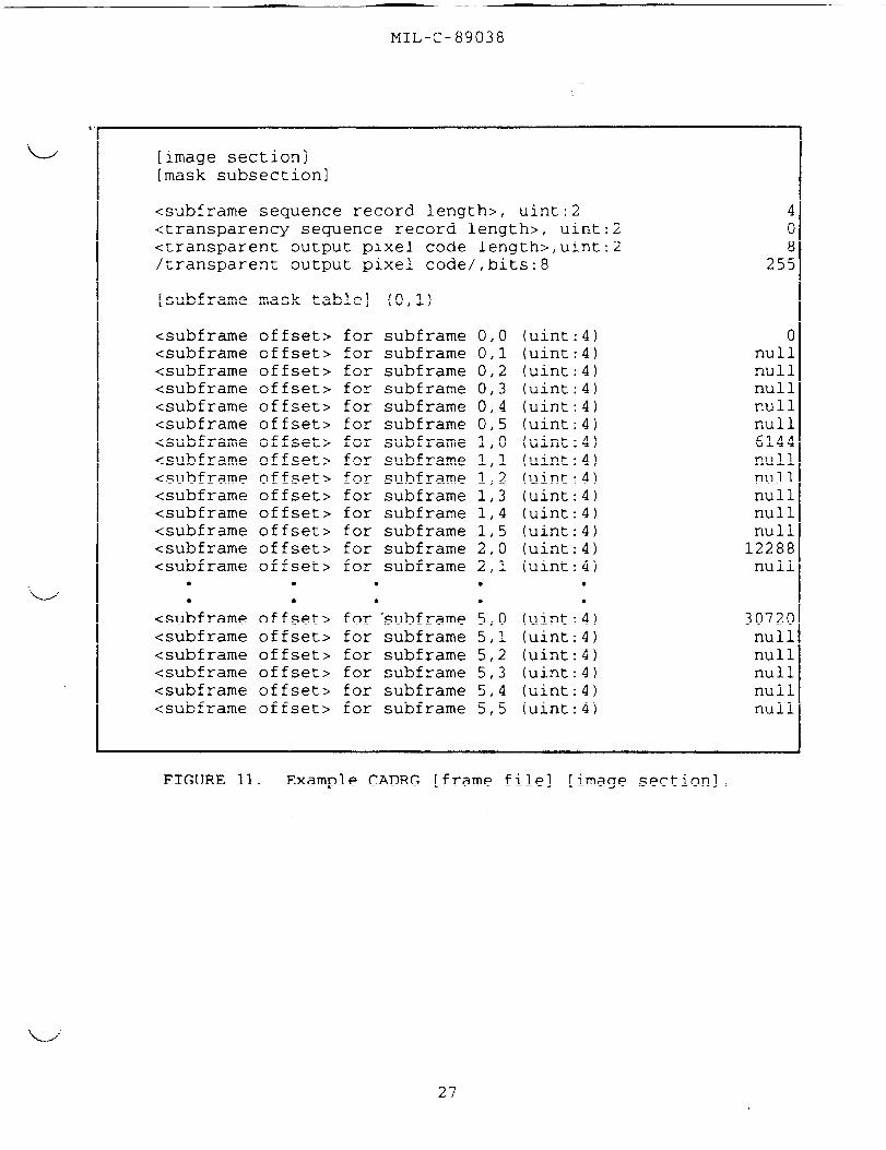
3.12.6 t? [~ae s~ . The [image section] containspointers to VQ compression kernels in the [compression section],that, in turn, point to color indices in the primary color tablewithin the [color/grayscale table section] . The structure anddata types for the [image section] in CADRG shall be as defined inMIL-STD-2411 . An example [image section] structure is shown inFIGURE 11. The [subframe mask table] and [transparency masktable] are described in MIL-STD-2411. Null values of (FFFF FFFF)Hin these tables indicate the subframes that contain no data, andsubframes that do not have transparent pixels. Transparentkernels (see 3.15) may be used on the edges of the image.
22

MI I~-c-89038
[compression section][compression section subheader]<compression algorithm id>,uint:2<number of compression lookup offset records>,uint:2
14c<number of compression parameter offset records>,uint:2
[compression<compression<compression
[compression<compression
lookuplookuplookup
subsection]offset tabletable offset
offset>,uint:4record length>,uint:2
record] (4 occurrences)
614
lookuplookup
table offsettable id>,uint:2 1
409648
62
<number of compression lookup records>,uint:4<number of values per compression lookup record>,unit:2<compression lookup value bit length>,unit:2<compression lookup table offset>,uint:4
<compression lookup table id>,uint:2<number of compression lookup records>,uint:4<number of values per compression lookup record>,unit:2<compression lookup value bit length>,unit:2<compression lookup table offset>,uint:4
24096
48
16446
<compression lookup table id>,uint:2<number of compression lookup records>,uint:4<number of values per compression lookup record>,unit:2<compression lookup value bit length>,unit:2<compression lookup table offset>,uint:4
34096
48
32830
<compression lookup table id>,uint:2<number of compression lookup records>,uint:4<number of values per compression lookup record>,unit:2<compression lookup value bit length>runit:2<compression lookup table offset (uint:4
44096
48
49214
[compression lookup table]Compression Table O: 4096<compression<compression<compression<compression
●
(4)4 byte indices:(o) = o 0 0(1) = o 14 0(2) = o 0 16(3) = o 4 0
● ●
● ●
4 byte indices:(o) = 12 88 50(1’)= 59 50 50(2’)= 142 174 44.
● ●
!.4 by;e indices;
16K Byteslookuplookuplookuplookup●
●
value>value>value>value>Q●
6108
Com~ression Table 1: 4096<compression lookup value><compression lookup value><compression lookup value>
● ● ●
16K121244
Bytes
●
Com~ression T;ble 2: 4096Compression Table 3: 4096 4 byte indices: 16K Bytes
FIGURE 9. 1P C~RG [-e filel [co~r-n sect~ .
16K Bytes
“---”
23

MIL-c-89038
[color/grayscale section][color/grayscale section subheader]
<number of color/grayscale offset records>,uint:l .
<number of color converter offset records>,uint:l .d
<external color/grayscale file name>,asci:12 <sp> fillet
[colormap subsection]<colormap offset table offset>,uint:4<color/grayscale offset record length>,uint:2
[colormap offset table][color/grayscale offset record)<color/grayscale table id>,uint:2<number of color/grayscale records>,uint:4<color/grayscale element length>,uint:l<histogram record length>,uint:2<color/grayscale table offset>,uint:4<histogram table offset>,uint:4
[color/grayscale offset record]<color/grayscale table id>,uint:2<number of color/grayscale records>,uint:4<color/grayscale element length>,uint:l<histogram record length>,uint:2<color/grayscale table offset>,uint:4<histogram table offset>,uint:4
[color/grayscale offset record]<color/grayscale table id>,uint:2<number of color/grayscale records>,uint:4<color/grayscale element length>,uint:l<histogram record length>,uint:2<color/grayscale table offset>,uint:4<histogram table offset>,uint:4
[color/grayscale element group][color/grayscale table] (2 1)[color/grayscale record] (216)Color Table O: 216 4-byte records:<color/grayscale element (0) = 3 17 168 29<color/grayscale element (1) = 247 243 243 244<color/grayscale element (2) = O 0 0 0<color/grayscale element (3) = 242 228 224 231● ● ● ● ●
864
f17
221[
44
571113
23244
9211977
21644
10492105
Bytes
~color/gra~scale e;ement (21;) = 57 i4 126 68<color/grayscale element (215) = 99 47 70 65
J
FIGURE 10. le CADRG [- filel [c~r/u_ravscale sectio~ .
w

MIL-C-89038
Color Table 1: 32 4-byte records:<color/grayscale element (0) = 23<color/grayscale element (1) = 229<color/grayscale element (2) = 236<color/grayscale element (3) = 2● ● ● ●
~color/gra~scale e~ement (30~ = 60<color/grayscale element (31) = 24
Color Table 2: 16 4-byte records:<color/grayscale element (0) = 29<color/grayscale element (1) = 221<color/grayscale element (2) = 213<color/grayscale element (3) = 2● ● ● ●
~color/gra~scale e~ement (14; = 80<color/grayscale element (15) = 63
38224231
0●
:39
43214210
1●
;574
[histogram element group][histogram table] (3)[histogram record] (216)Histogram Table O: 216 4-byte records:<histogram<histogram<histogram<histogram● ●
● ●
element>element>element>element>
●
●
<histogram element><histogram element>
Histogram Table 1:<histogram element><histogram element><histogram element><histogram element>● ● b● ● ●
<histogram element><histogram element>
(0) = o(1) = 7450(2) = 898(3) = 14
●
(214) = :0(215) = O
32 4-byte records:(o) = o(1) = 6(2) = 7475(3) = 1098
●
(30) = 1;1(31) = 219
170110227
2
9635
162113195
2
12156
12848
212232
0
5416
6452
204209
1
3480
864
128
Byte:
Byte:
Bytes
Bytes
25

MIL-c-89038
Histogram Table 2: 16 4-byte records:<histogram element> (0) = 5<histogram element> (1) = 44<histogram element> (2) = 7605<histogram element> (3) = 1794
● ● ● ●
●
~histogram”element~ (14) = O<histogram element> (15) = 286
[color
<color<color<color
[color[color<color
converter
converterconverterconverter
converterconverterconverter
<number of color<color converter
subsection]
offset table offset>,uint:4offset record length>,uint:2record length>,uint:2
offset table]offset record]table id>,uint:2converter records>,uint:4table offset>,uint:4
<source color/grayscale table offset>,uint:4<target color/grayscale table offset>,uint:4
[color converter offset record]<color converter table id>,uint:2<number of color converter records>,uint:4<color converter table offset>,uint:4<source color/grayscale table<target color/grayscale table
Color Converter Table O: 216<target color/grayscale table<target color/grayscale table<target color/grayscale table<target color/grayscale table● ● ● ●
● ● ● ●
<target color/grayscale table<target color/grayscale table
Color Converter Table 1: 216<target<target<target<target●
●
<target
color/grayscalecolor/grayscalecolor/grayscalecolor/grayscale
● 9● ●
color/grayscale
tabletabletabletable
●
●
tabletable
offset>,uint:4offset>,uint:4
4-byte records:entry number> (Oentry number> (1entry number> (2entry number> (3
entry number> (214)entry number> (215)
4-byte records:entryentryentryentry
entry
number> (0)number> (1)number> (2)number> (3)
number> (214)
64 Byte
8640232
1322
8640232
159“
c
21i4((
2:
Bytes
Bytes
<tarqet color/qrayscale entry number> (215)
FIGURE 10. 1eDDRG [h filel [color/uravscalesectmnl (cc)~ .
26
MIL-c-89038
%
[image section][mask subsection]
<subframe sequence record length>, uint:2 4<transparency sequence record length>, uint:2 o<transparent output pixel code length>,uint:2 8/transparent output pixel code/,bits:8 255
[subframe mask table] (0,1)
<subframe offset> for subframe 0,0 (uint:4) o<subframe offset> for subframe 0,1 (uint:4) null<subframe offset> for subframe 0,2 (uint:4) null<subframe offset> for subframe 0,3 (uint:4) null<subframe offset> for subframe 0,4 (uint:4) null<subframe offset> for subframe 0,5 (uint:4) null<subframe offset> for subframe 1,0 (uint:4) 6144<subframe offset> for subframe 1,1 (uint:4) null<subframe offset> for subframe 1,2 (uint:4) null<subframe offset> for subframe 1,3 (uint:4) null<subframe offset> for subframe 1,4 (uint:4) null<subframe offset> for subframe 1,5 (uint:4) null<subframe offset> for subframe 2,0 (uint:4) 12288esubframe offset> for subframe 2,1 (uint:4) null
● ● ● ● b
<su~frame off~et> for’’subframe ~,0 (uint:~) 30720<subframe offset> for subframe 5,1 (uint:4) null<subframe offset> for subframe 5,2 (uint:4) null<subframe offset> for subframe 5,3 (uint:4) null<subframe offset> for subframe 5,4 (uint:4) null<subframe offset> for subframe 5,5 (uint:4) null
FIGURE 11. Example CADRG [frame file] [image section] .
‘L’
27
. -

MIL-C-89038
[image description subheader]<number of spectral groups>,uint:2 1<number of subframe tables>,uint:2 (<number of spectral band tables>,uint:2 3<number of spectral band lines per image row>,uint:2 1<number of subframes in east-west or left-right
direction>,uint :2 6<number of subframes in north-south or up–down
direction>, uint:2 6<number of output columns per subframe>,uint:4 256<number of output rows per subframe>,uint:4 256<subframe mask table offset>,uint:4 7<transparency mask table offset>,uint:4 null
[image display parameters subheader]<number of image rows>,uint:4 64<number of image codes per row>,uint:4 64<image code bit length>,uint:l 12
[spatial data subsection][spectral group] (1)[subframe table] (1, 36)[spectral band table] ”~i)[image row] (64)[spectral band line] (1)/image code/,bits:12 (64) .{Sample Below}
Codebook: I 1024 I 2048 I 3072 I 4095 I12-bit Values: I 400 I 800 I coo I FFF IBytes: I 40 I 08 I 00 I CO I OF IFFI
/image code/s:58 1690 1252 0786 1814 1808 0643 2913667 3267 3917 3794 1644 1059 36 2725
1466 3532 1338 1203 3860 1739 220 1310● ● ● ● ●
● ● ● ● ●
FIGURE 11. le CADRG [fr~e filel (~ae sectlonl
~.
28

MIL-C-89038
‘u;
3.12.7 (a~e sect- . The [attribute section]will define ancillary or qualifying data about the overall frameimage or areal subsets of the image. The structure and data typesfor the [attribute section] shall be as defined in MIL-STD-2411.An example [attribute section] structure is shown in FIGURE 12.
a. Pointers to attributes and one or more parameters forthose attributes are enumerated for each areal extent in the[offset record]s. The <parameter offset>s in these records pointto the actual values or codes for the parameters in the [attributerecord]s.
b. The attribute descriptions and their identifiers, andparameter descriptions and identifiers for CADRG are listed inAPPENDIX 50. The actual values/codes used for <parameter value>sin [attribute record]s shall be as defined in MIL-STD-2411-1.
c. If the areal extent of the values for a given’ attributeis an entire frame, then the <areal coverage sequence number>sshall be set to zero. otherwise, they shall point to an [explicitareal coverage record] which contains three or morelatitude/longitude vertices of the areal extent for the attributeparameters; the areal extent may be irregularly shaped.
3.12.8 Xhe lre~ace/~t,e ,ec~onl . The [replace/updatesection] will provide the genealogy of the [frame file) throughsuccessive replacements (editions) and updates. It is includedfor all replacement and update [frame file]s. The structure anddata types for the [replace/update section] in the CADRG productshall be as defined in section 5.1.6 of MIL-STD-2411.
3.13 Storaae re~~~ts . Including overhead, the CADRGimage data is approximately 55:1 compressed with respect to thesource A.DRG image data. The storage requirements for these itemsare discussed in APPENDIX 40. For CADRG, as much as 650 Mbytescan be stored on a CD-ROM. Storage on other distribution mediawill be appropriate to the data capacity of that media.
‘u’
29
,._.

MIL-C-89038
[attribute[attribute<number of<number of<attribute<attribute
[attribute[attribute[attribute<attribute<parameter
section] (O, 1)section subheader]attribute offset records>,uint:2 3(explicit areal coverage records>,uint:2offset table offset>,uint:4 ioffset record length>,uint;2 [
subsection]offset table]offset record]id>,uint:2 1id>,uint:l 1
<areal coverage sequence num.ber>,uint:l<attribute record offset>,uint:4
[attribute offset record]<attribute id>,uint:2<parameter id>,uint:l<areal coverage sequence number>,uint:l<attribute record offset>,uint:4
[attribute offset record]<attribute id>,uint:2<parameter id>,uint:l<areal coverage seguence number>,uint:l<attribute record offset>.uint:4
[attribute offset record]<attribute id>,uint:2<parameter id>,uint:l<areal coverage sequence number>,uint:l<attribute
●
●
[attribute[attribute<parameter<parameter<parameter<parameter
●
●
71c
304
record offset>,uint:4 3oi●
b
table]record]values>:values>:values>:values>:
●
●
● ●
● ●
Currency Date (asci:8) 19940122Production Date (asci:8) 19940122Horizontal DatumSignificant Date
● ●
● ●
asci:4) WGEasci:8) 19830914
●
●
,uint:4 8
[explicit areal coverage subsection]<explicit areal coverage table offset:<explicit areal coverage record length>,uint:2 82<corner coordinates record length>,uint:2 16
‘d
FIGURE 12, le CADRG [frame filel [attribute sectlonl
30

MIL-C-89038
.“,
[explicit areal coverage table][explicit areal coverage record]<number of vertices>,uint:2 = 5[corner coordinates record]<lat>,real:8 = 0.000000<long>,real :8 = 143.500000<lat>,real:8 = 40.000000<long>,real :8 = 143.500000<lat>,real:8 = 40.000000<long>,real :8 = -156,000000<lat>,real:8 = 0.000000<long>,real :8 = -156.000000<lat>,real:8 = 0.000000<long>,real :8 = 143.500000
[explicit areal coverage record]<number of vertices>,uint:2 = 5[corner coordinates record]<lat>,real:8 = 0.000000<long>,real :8 = 143.500000<lat>,real:8 = 40.000000<long>,real :8 = 143.500000<lat>,real:8 = 40.000000<long>,real :8 = -156.000000<lat>,real:8 = 0.000000<long>,real :8 = -156.000000<lat>,real:8 = 0.000000<long>,real :8 = 143.500000
[exDlicit areal coverage record]enu~ber of vertices>,uint:2 =[corner coordinates record]
5
<lat>,real:8 = 40.000000<long>,real:8 = 143.500000<lat>,real:8 = 40.000000<long>,real :8 = 145.000000<lat>,real:8 = 0.000000<long>,real :8 = 145.000000<lat>,real:8 = 0.000000<long>,real :8 = 143.500000<lat>,real:8 = 40.000000<long>,real:8 = 143.500000
FIGURE 12. le CADRG (fr~ file] [attribute +ectlonl~.
L/’
31

MIL-c-89038
3.14 RG deco~ . All information required fordecompression of a CADRG [frame file] is contained within the fileitself. Software for the decompression of CADRG data should be 4written so that offset values and file structures can changewithout needing to modify the application software. This sectiondescribes the specific parameters required for the decompressionof CADRG data. other compressed products conforming to the RPFstandard will require different parameters and processing fordecompression. These values will be described in thespecifications for each product.
3.14.1 Dvervieu . CADRG decompression involves replacingcodes in the compressed image with pixel values for use in displayor exploitation of the data. This decompression is done in a twostep process as shown in FIGURE 13. A compressed subframeconsists of a 64 x 64 array of 12-bit codes. Each of these codes,during spatial decompression, is converted to a 4 x 4 block ofdecompressed pixels. Each pixel in this 4 x 4 block is an indexinto the color table, allowing it to have an RGB or monochromaticvalue. When decompressed, the output subframe is 256 x 256 pixelsin size. The first 4 x 4 block is in the upper left hand cornerof the subframe. The decompression continues across the first rowthrough the first 64 codes. The 65th 12-bit code (/image code/number 64) is used to decompress the first 4 x 4 block on thesecond row of the subframe. Decompression continues in this “rowmajor” fashion until the entire subframe has been spatiallydecompressed. The output from the spatial decompression processdescribed above is a 256 x 256 array consisting of indices to a216 entry color table. A 217th entry (index 216) is a null valuethat represents “transparent” pixels (see 3.15) in a [frame file]that contains transparent pixels, The final decompression stepinvolves color decompressing the subframe indices into their red,green blue (RGB) or monochromatic (M) pixel values. Each of the217 entries in the CADRG color table contains an (RGB) and (M)pixel value that is in the range O-255. Each pixel of a final RGBoutput image, therefore contains a 24-bit argument. However,because only 216 of the available 16.7 million colors are used inthe subframe, the final image can be displayed with no color lossusing 8-bits. Section 3.14.2 and 3.14.3 describe the steps of thedecompression process in detail.
3.14.2 Snatial deco~ress~ . The CADRG compression sectioncontains four [compression lookup table)s. Each of the tablescontains the decompressed pixels for one of the rows of thecompression vector. For a particular /image code/ n, there is anentry in each of the four tables. The resulting decompressedpixels from the four compression tables can be combined to form asingle 4 x 4 block. A description of the logical steps tospatially decompress a 4 x 4 block is provided below.
32

MIL-C-89038
FIGURE 13. process Flow for CADRG ~eco~essio~ .
Compramalon Codobook in ,J~patiallyDecompresaad Image.,1 .
IO RGBM.RQBX.RC3BM. RG.
P
R. GEM. R(3BM. RC3BM
216 RQBM
a. Each /image code/ has a value ranging from O to 4095,representing a particular code word. The /image code/ is used asan index into each of the 4 [compression lookup table]s. Eachrecord of a [compression lookup table] contains 4 /compressionlookup value/s. Therefore, the /image code/ indexes a 4 x 4 blockof /compression lookup value/s (4 per row with 4 rows) . AS shownin FIGURE 14, each row of the compression codebook contains4096 /compression lookup value/s for each row position. Each ofthese index values ranges from O to 215 (216 for transparentpixels) and represents an index into the color table.
b. If a compressed /image code/ in the [image section]contains the value n, then the 4 x 4 color table indices,represented as /compression lookup value/s in the [compressionsection], can be found first by using the [location section] todetermine the starting byte of the [compression section] . If welet the offset to the start of first compression table berepresented by Al, then the location of the first 4 /compressionlookup value/s for n would be located at thepositions within the [compression section]:
LocationLocation
LocationLocation
forfor
forfor
value Ovalue 1
value 2value 3
rowrow
rowrow
o0
00
Al +Al +Al +Al +
44
44
xxxx
following byte
nnnn
‘(1)+ 1
+ 2+ 3
33

MIL-C-89038
c. The location of the next row of color index /compressionlookup value/s would be offset 16,384 (4 x 4096) bytes from thestart of the first row of values. If its offset was A2 then thelocation of the second 4 values for n (the second row of 4 colortable index values) would be at the following byte positionswithin the [compression section] :
Location for value O, row 1 = A2 + (4 x n)Location for value 1, row 1 = A2 + (4 x n) + 1Location for value 2, row 1 = A2 + (4 x n) + 2Location for value 3, row 1 = A2 + (4 x n) + 3
(2)
d. The location of the color table index /compression lookupvalue/s for rows three and four would be similarly offset by32,768 bytes and 49,152 bytes, respectively. It should be notedthat the offset values for each of the [compression lookup table]sis included in the [compression lookup subsection] . Programmersshould always examine the offset values to determine the startinglocation for each table.
e. To decompress the first 16 pixels of the map (4 x 4section of the map located in the upper-left corner) , the first12-bit /image code/ (/image code/ number ‘O) would be used as anindex to the 4 rows of 4 color table index /compression lookupvalue/s in the [compression section] . These 16 indices would beused as lookup values for the color table, and the 4 rows of 4Red-Green-Blue or Monochrome values would be placed in the upper-left corner of the decompressed image. The decompression processcontinues across the columns and down the rows (see 3.14.1) . Inall, 4096 (64 x 64) groups of 4 x 4 pixels are placed into theoutput decompressed image for each subframe.
f. Although the description provided above can be used todecompress the image by sequentially decompressing the 4096 (64 x64) compression vectors, the order of the decompression steps maybe modified. Some applications may choose to decompress an entirerow of the subframe at a time. This approach is made possible bythe four separate compression tables for each image row.
3.14.3 Cdm dec~ . The [color/grayscale table] inthe [color/grayscale section] consists of either 216 or 217entries, each of which contains 4 bytes. The first byte containsthe red intensity level, the second byte contains the greenintensity level, the third byte contains the blue intensity leveland the fourth byte contains a monochrome (grayscale) intensitylevel, which is an arithmetic combination of red, green and blueintensity levels. The equation used to calculate the monochromeintensity level is:
Monochrome Value = 0.299 (Red) + 0.587 (Green) + 0.114 (Blue) (3)
34

MIL-C-89038
reomtpression ~ectio~~
Compxaaaion’Algorithm ID,Table Offsets, and Record Count Information
J
[compression lookup table]
Byte Field Description
Al Row O, Code O, Color Indices 0,1,2,3Al+l Row O, Code 1, Color Indice~ 0,1,2,3A1+2 Row O, Code 2, Color Indices 0,1,2,3A1+3 Row O, Code 3, Color Indices 0,1,2,3
● ● ● *.*..* ..*..*● ****** ......
;i+16380 Row O, Code 4095, Color Indices 0,1,2,3---.-------------------------------------------------------
A2 Row 1, Code O, Color Indices 4,5,6,7A2+1 Row 1, Code 1, Color Indices 4,5,6,7A2+2 Row 1, Code 2, Color Indices 4,5,6,7A2+3 Row 1, Code 3, Color Indices 4,5,6,7● ● .............
;;+16380 ;; “i,“Yodi”i(i95, Color Indices 4,5,6,7----------------------------------------------_---------_.-
A3 Row 2, Code O, Color Indicee 8,9,10,11A3+1 Row 2, Code 1, Color Indices 8,9,10,11A3+2 Row 2, Code 2, Color Indices 8,9,10,11A3+3 Row 2, Code 3, Color Indices 8,9,10,11.. ..**..* ......
.......i;+16380 ;;; “2”,0Code 4095, Color Indices 8,9,10,11.---------------------------------------- --------_---------h4 Row 3, Code O, Color Indices 12,13,14,15k4+l Row 3, Code 1, Color Indices 12,13,14,15A4+2 Row 3, Code 2, Color Indices 12,13,14,15&4+3 Row 3, Code 3, Color Indices 12,13,14,15● ● .**..** ......
;i+16380 ;;;”3*,”c*~;0~;;5, Color Indices 12,13,14,15
FIGURE 14. le File out of [co~ion sectl~ .
a. Each byte that resulted from the spatial decompressionprocess 1s used as an index into the color table. The result ofeach lookup procedure is a four-byte value, which represents thered, green, and blue (RGB) color intensities for a particularpixel, and a one-byte monochromatic (grayscale) value (seeEQUATION 3) for a particular pixel in the subframe. In general,either the RGB or the monochromatic value is used to display theImage.
b. Each byte in the spatially decompressedinteger in the range 0-215(216). The values are
matrix will be anused as lookup
35

MIL-C-89038
values into the color table. The 216(217) entries in the colortable contain RGB and monochrome values in the range O - 255,arranged as shown in FIGURE 15. The entries in the color tablerepresent RGBM values for pixels in the digitized map thatrepresent digitized map data. Entry 216 is reserved for“transparent” pixels, for cases where the data is missing oravailable at the given geographic location. The RGBM valuesthe CADRG color table for the 217th entry (index 216, fortransparent pixels) are O, 0, 0, 0.
c. A value of m in the spatially decompressed subframebe used to determine the RGB values of a pixel in the output
notin
canimaqe
first by using the [location section] to determine the starting -byte of the [color/grayscale section]. If we let B represent theoffset to the [color/grayscale section], then the location of theRGBM values for m would be located at the following byte positionwithin the [color/grayscale section] :
Location for RGBM Value = B + (4 x m)
d. To reconstruct the image, each l-byte element from thespatially decompressed matrix is replaced by the RGB or M valuesthat were derived during color decompression. The RGB ormonochrome matrix obtained from this step becomes the decompressedCADRG subframe.
(4)
rcolor/g~ay8cale section]
Color Table Information, includingTable Offsets and Record Counts
J
[color/graYscale table]s
Byte Field Description
B Index O RGBMB+4 Index 1 RGBMB+O Index 2 RGBMB+12 Index 3 RGBM
~
RGB and GrayecaleB+16 Index 4 Indices
● ● ..***..
Bi860 ;;;;; “2i5 RGBMB+864 Index 216 0000
TransparentIndex
FIGURE 15. le File Lav~ut of (cQlor/~vscale sec~onl .
36

MIL-C-89038
‘w
“w
:. .
3.15 RG IJ@te Fib . CADRG files ~re compliant with theRaster product Format and therefore they contain a configurationcontrol mechanism to support updating. The mechanism exploits thesubframe aspects and the [replace/update section] of RPF.
To avoid redundancy, and because some of the sections andsubsections within RPF are optional, a CADRG update file does notcontain all of the information that a full CADRG file contains.The following paragraphs detail which sections are necessarywithin the update file and which optional sections are notrecorded.
3.15.1 Pect~ . The [header section] of a CADRGupdate file shall conform to section 3.12.1 of this document andMIL-sTD-2411. In addition, the <new/replace/update indicator> ::=2 to indicate that the file is an update file.
3.15.2 . The [location section] of a CADRGupdate file shall conform to section 3.12.2 of this document andMIL-sTD-2411.
3.15.3 aae sec~ . The [coverage section] shall notbe included in the CADRG update file. All information requiredfor the [coverage section] exists in the file which is beingupdated.
3.15.4 S~tio~ . The [compression section] isnot included in the CADRG update file. All information needed todecompress the image data of the update file exists in the filewhich is being updated.
3.15.5 1P Sect- . only part of the[color/grayscale section] is necessary in an update file. The[colormap subsection] which contains updated histograms isincluded. In addition, the update file includes the[color/grayscale element group]; by design, the [color/grayscaleelement group] included in the update file is identical to the[color/grayscale element group] in the parent file. The[color/grayscale section subheader] is included in the update filebecause it contains information needed to decode the [colormapsubsection] of the update file. The [color converter subsection]is not included in the CADRG update file.
3.15.6 tlon . The [image sectio:n] is necessa~ inan update file. The [spatial data subsection] contains allsubframes to be replaced in the CADRG file to be updated. The[mask subsection] of the update file defines the spatial locationof those new subframes. The [image description subheader] and the[image display parameter subheader] are also included in the CADRGupdate file.
37
MIL-C-89038
3.15.7 tr~tim . The [attribute section] of anupdate file contains new attribute information about the file andis therefore included.
3.15.8 Sect.h . The [replace/update section]is included in an update file and is as defined in 3.12.8. andMIL-sTD-2411.
3.16 t DIXel~ . Subframes that are partiallyfilled by the image coverage area are padded with transparentpixels color index code (set to 216) during data production. A 4x 4 kernel in a subframe that contains at least one transparentpixel is replaced by the 12-bit /image code/, represented by index4095. This entry represents a transparent kernel in any framethat contains transparent pixels. If no transparent pixels arepresent then index 4095 will be used for colors. The last<color/grayscale element> (index 216) in the [color/grayscaletable) is set to O (black) to represent a transparent *color. ” Ifapplication software encounters index 4095 in a frame containingtransparent pixels, it may color decompress to display black, orremap the transparent kernel to a system-specific transparentcolor. In such a case, the /compression lookup value/s in theindex 4095 kernel point to the index 216 <color/grayscaleelement>. user software can map this value to a system-specifictransparent pixel color. MIL-STD-2411 defines two fields, the/transparent output pixel code/ and the <transparent output pixelcode length> for use in frames with transparent pixels. ForCADRG, the /transparent output pixel code/ shall be set to 216 ifthere are transparent pixels and the <transparent output pixelcode length> field shall be set to 8, indicating that the/transparent output pixel code/ field is 8 bits long. If thereare no transparent pixels, the <transparent output pixel codelength> field shall be set to O and the /transparent output pixelcode/ is not recorded.
4. QUALITY ASSUFU.NCE PROVISIONS
4.1 Dect 10Q . Unless otherwisespecified in the contract or purchase order, the contractor isresponsible for the performance of all inspection requirements(examinations and tests) as specified herein. Except as otherwisespecified in the contract or purchase order, the contractor mayuse his own or any other facilities suitable for the performanceof the inspection requirements specified herein, unlessdisapproved by the Government. The Government reserves the rightto perform any of the inspections set forth in this specificationwhere such inspections are deemed necessa~ to ensure supplies andservices conform to prescribed requirements.
‘4
4.1.1 ResDo~slbllltv,.,
for co~ . All items shall meetall requirements of paragraphs 3 and 5. The inspection set forthin this specification shall become a part of the contractor’soverall inspection system or quality program. The absence of anyinspection requirements in the specification shall not relieve the u
38

MIL-c-89038
contractor of the responsibility of ensuringb~~hat all products orsupplies submitted to the Government for acceptance comply withall requirements of the contract. Sampling inspection, as part ofmanufacturing operations, is an acceptable practice to ascertainconformance to requirements; however, this does not authorizesubmission of known defective material, either indicated oractual, nor does it commit the Government to accept defectivematerial.
4.2 of nect~ . The inspectionrequirements specified herein are classified as follows:
a. First article inspection (see 4.3).
b. Quality conformance inspection (see 4.4).
4.3 -St artl~le l~ectlon , When a first articleinspection is required (see 3.1 and 6.2), it shall be examined fordefects specified in 4.4.1 and tested as specified in 4.4.2.
4.4 1tv con~ce lns~ectl~ . The CADRG frame filesshall be examined for defects and errors as specified in 4.4.1.Required corrections shall be made to all files before being sentto the next production stage. Defects detected during theinspection of the frame files shall be evaluated by DMA forcriticality an suitable corrective action.
4.4.1 yes=. The following classes of defects and errors
‘u’ will be tested for:
a. Horizontal Accuracy. Frame files will be inspected toensure that a horizontal accuracy of plus or minus one-half pixelwith respect to the source ADRG is maintained.
b. Visual Appearance. Each frame file will be inspectedfor overall color appearance. Each frame file will be inspectedfor feature loss due to color appearance.
c. Attribute Data. Frame files will be inspected to ensurethe accuracy of textual attribute data.
d. Standards Compliance. Each frame file will be inspectedto ensure compliance with ISO 9660, MIL-STD-2411, MIL-sTD-2500,and this specification.
4.5 Review of c~uct Lon recor~ . Records about theconstruction of the frame files shall be maintained. The recordsshall document sources, decisions regarding reconciliation ofconflicting data, etc. Frame file records/construction historiesshall be reviewed concurrently with visual examinations (see4.4.1) to ensure that proper cartographic procedures have beenfollowed.
L/-”
39

5. PACKAGING
MIL-C-89038
5.1 GQnQuL1. CADRG shall be distributed on CD-ROMs,distributed in clear plastic cases (also known as “jewel boxes”) .Each CD-ROM shall be labeled to indicate the cartographic contentsof the CD-ROM, map projection, map scale, security restrictions(if any), distribution limitations, producer (Government agency orcontractor) , library number, DMA stock number bar code, editionnumber and date. The jewel boxes shall contain the informationprinted on the CD-ROM, plus a location diagram, and an informationbooklet. The printing and finishing requirements are specified inDMA Technical Instruction TI/2DJ/001.
5.1.1 ~ . CADRG CD-ROMs will be color coded toindicate the highest level of classification of the contents ofthe volume. FIGURES 16a and 16b shows possible label formats forthe unclassified and classified CD-ROMs. The label format forspecific CD-ROMs will depend upon the contents of the CD-ROM.
a. UNCLASSIFIED labels will have a white background, and thetext and symbols shall be overprinted in black.
b. CONFIDENTIAL labels will have a dark blue background, andthe text and symbols shall be overprinted in white.
c. SECRET labels will have a red background, and the textand symbols shall be overprinted in white.
d. TOP SECRET labels will have an orange background, and thetext and symbols shall be overprinted in black.
5.1.2 bo~attin diaar~ . The jewel-box liner (also known asa tray card) may include a Location Diagram, which is a graphicdepiction (see FIGURE 17) of the geographic location of thecartographic contents of the interchange volume.
5.1.3 tion bookl~ . M information booklet willprovide general information about the contents of the CD-ROM,handling instructions, user and distribution information, and DMApoints of contact. FIGURE 18 shows the format of the informationbooklet covers.
5.1.4 . Each CD-ROM in the CADRG libraryshall be indexed to facilitate configuration management, includingupdates, additions, and replacements. The format convention ofthe alphanumeric value of a bar-coded DMA stock number forstandard CADRG distribution is a fifteen character identifieraccording to the following description:
“u’
/ 7A.
a. For all series, the first five positions are always“CDRG<blank>” .
40
i I m Wn

MIL-c-89038
b. The remaining ten characters are def~ned by theparticular series (see 5.4.1).
‘L./
1. GNC/JNC: “GNCJNCn<blank><blank><blank>” , where n is “N”for the northern hemisphere, or “S” for the southern hemisphere.
2. ONC/TPC: “ONCTPCnn<blank><blank>” , where nn is a numberbetween 01 and 20 designating the pre-defined geographical area.
3. JOG : “5aabbnnmm<blank> ‘I,where 5 designates this as a JOGvolume and aabbnnmm designates a bounding rectangle: aa is theJOG band nearest the equator, bb is the JOG band farthest from theequator, nn is the left JOG column, and mm is the right JOGcolumn.
4. TLM/City Graphics/Combat Charts: “7aannmmssr”, where 7designates this as a TLM volume and aannmmss is the block covered(aa is the JOG band, nn is the left JOG column, mm is the right JOGcolumn, and ss indicates the subblock (01-04)) . The r is usually ablank. However, when the addition of city graphics and combatcharts causes the subblock to exceed the volume of a singledistribution media (i.e., CD-ROM), the subblock will further bedivided into regions. The r will then be an alpha character (A-Z) .
5. For special packages (see 5.4.2) the last ten characterswill be a name representative of the region or purpose covered bythe volume, i.e. RPFSAMPLER, SWRANGES<blank><blank>,SOMALIA<blank><blank><blank>, etc.
5.2 ~ackw . Packaging shall be level C (see 6.2) unlessotherwise specified. This packaging provides minimum protection,and is needed to protect material under known favorableconditions . The following criteria determine the requirements forthis degree of protection:
a. Use or consumption of the item at the first destination,
b. Shock, vibration, and static loading during the limitedtransportation cycle.
c. Favorable warehouse environment for a maximum of 18months.
d. Effects of environmental exposure during shipment and intransit delays.
e. Stacking and supporting superimposed loads duringshipment and temporary storage.
5.3 . In addition to any special markings requiredby the contract or order, markings shall be in accordance withrequirements of MIL-STD-129 for military levels of protection.
..u
-x nl
41
w

MIL-C-89038
5.4 ~. Interchange volumes may include anyreasonable combination of the CADRG and other RPF data on the samevolume. In addition, CADRG data from multiple scales may beincluded on a volume.
‘d’
42

MIL-c-89038
5.4.1. Normally, CADRG will be distributed (onCD-ROMs) without other RPF data, Standard packaging of CADRG byDMA will be as follows:
a. In support of aeronautical combat operations, CADRG willbe packaged in three distinct groupings: GNC and JNC, ONC andTPC, and JOG.
b. In support of ground combat operations, CADRG will bepackaged based on TLM coverage. The volume will include the TLMalong with associated JOGS, City Graphics, and Combat Charts.coverage will be provided as an overview.
c. other CADRG products (nautical charts, classifiedmaterials, etc. ) will be packaged by type and may be eitheruniform or mixed in scale.
d. CADRG of non-DM.A charts will generally be packaged in
ONC
amanner corresponding to their DMA counterparts. For exarnDle, UKLFC and TFC would be packaged as if they were TPC and JOG”. ‘
5.4.2 In support of crisis, special, and/or reoccurringbroad-based user requirements, CADRG will be geopackagedvertically (all scales) and with other RPF products coveringdiscrete geographic regions. For example, data sets can beidentified for test ranges, major training centers, or crisisareas where integrated datasets with mixed data types and scalesare needed by large numbers of users.
43

MIL-c-89038
DISTRIBUTION STATEMENT
Defense Mapping Agency
DATA STORAGE
“--J”
FIGURE 16a. F-t for .
44
———————- —- —x<—___—_— _ ________ _— ______ _. _____ _ _——..——.—-= - .—..._=._—_

MIL-C-89038
)a.lf?$i”aDATASTORAGE
-(Producedby:
)
nszk~
Defense Mapping AgencyAerospace Center
St Louis, MO
\l Shck No:
CD-ROM ,\ ~,,qaql
Y
FIGURE 16b. ~a~e Label Fo~t for Classlf~d ~--,,
.
45

MIL-C-89038
00° N
00° N
CLASSIFICATION AND CONTROL MARKING4 }
LOCATION DIAGRAM
00°w 00°N
SHADED AREA IS ACTUALCOVERAGE ON CD-ROM
I
00° N
Approximate Geographic Coverageof the Contents of this Disc:
()()0()()’Nto~“()()’N00°00’E tO00°00’E
.
00°N
00° N
00° N
FIGURE 17. le For~t f~r Loc- J-)w .
‘=./;
.
46
I

MIL-c-89038
Compressed ARC Digitized RasterGraphics
EEEEEl
[ DISTRIBUTION STATEMENT I
Producedby. ApproximateDefense Mapping Agency Geographic Covera e
Aerospace Center ~“()()’ N to ()(j”~’ iSt Louis, MO 00”W%E to 00°00’ E
o
T>
&Edh,..:_] @l~~fiSeries:
Stock NO: DATA STGW3E
m
Ttvs Disc containsADRG collected from
MAP SHEET INFORMATION I
I UPDATE NOTES FOR CD-ROM I
BAR CODE / STOCK NUMBER (DMA USE)
lmllllllnllllllllllllllllnIllIllCDRG XX XXX------ -----
FIGURE 18. t for Boo~P~ .
47
1

MIL-c-89038
6. NOTES(This section contains information of a general or explanatorynature that may be helpful, but is not mandatory. )
6.1 mkrlkhx. This specification is intended to provideguidelines for the preparation and use of CADRG data to supportvarious weapons, C31 theater battle management, mission planning,and digital moving map systems. This specification is a newpublication and does not supersede any other publication.
a. CADRG image data is of appropriate size and quality foruse in military command and control systems, ground-based force tounit-level mission planning systems, and aircraft cockpit “movingmap” displays. The post-reduction filtering scheme emphasizeslegibility of text and contour lines to ensure that displayed andprinted digital maps are readable and distinct. CADRG is intendedto satisfy the needs of a broad range of users in its compressionratio, display and print quality and displayed screen size.
b. The 55:1 reduction in size of CADRG compared to sourceADRG offers distinct operational, logistical, and supportabilitybenefits to many users of digitized map/chart and image~ data.It permits the same datasets to be used for both ground-based andaircraft cockpit displays, offers significant savings in mediastorage/transportation and peripherals (i.e. , hard disk) costs,results in faster data loading times and requires less frequentreloading of hard disks from media. It also allows multiple scaleand product types- to be placed on interchange media for geographicareas of interest.
c. CADRG [frame file]s may be physically formatted within aNITF message.
6.2 . Acquisition documents mustspecify the following:
a. Title, number, and date of this specification.
b. Issue of DODISS to be cited in the solicitation, and ifrequired, the specific issue of individual documents referenced(see 2.1.1 and 2.2.2).
c. When a first article is required (see 3.1, 4.3, and 6.3).
d. Levels of packaging (see 5.2) t
“-/’
6.3 ~st article . When a first article is required, itshall be inspected and approved under appropriate provisions ofFAR 52.209. The contracting officer shall specify the appropriatetype of first article and the number of units to be furnished. .The contracting officer shall also include specific instructionsin acquisition documents regarding arrangements for selection,inspection, and approval of the first article.
48

MIL-c-89038
L/-’
“’k-”
6.4 &xQnYms* ..J,&.L
ADRG ARC Digitized Raster GraphicsANSI American National Standards InstituteARc Equal Arc-Second Raster ChartATC Air Target Chart
CADRG Compressed ADRGCD-R Compact Disk - RecordableCD-ROM Compact Disk – Read Only Memo~
DIS Draft 1S0 StandardDMA Defense Mapping Agency
FIPS PUB Federal Information Processing Standardpublication
GNC Global Navigation Chart
IEC International Electrotechnical CommissionIEEE Institute of Electrical and Electronic EngineersIFS Independent File System1S0 International Standards Organization
JNC Jet Navigation ChartJOG Joint Operations GraphicJOG-A Joint Operations Graphic – AirJOG-R Joint Operations Graphic – Radar
LFC Low Flying Chart (UK)
ONC Operational Navigation Chart
RPF Raster Product FormatRGB Red–Green–Blue
TFC Transit Flying Chart (UK)TLM Topographic Line MapTPC Tactical Pilotage Chart
VQ Vector Quantization
WGS-84 World Geodetic System – 1984
6.5 atlon aareem~~ . Certainprovisions of this specification may be subject to internationalstandardization agreements. When amendment, revision, orcancellation of this specification is proposed that will modifythe international agreement concerned, the preparing activity willtake appropriate action through international standardizationchannels, including departmental standardization offices, tochange the agreement or make other appropriate accommodations.
49
-.>[3 1-11

MIL-C-89038
6.5.1 5 (s~s)STANAG 2211,
.“Geodetic Datums, Spheroids, Grids, and Cell
References .“
6.5.2 ts (~ .This section is not applicable to this specification.
6.5.3 ~ St~ation co~g C-ttee (ASCC)
~. This section is not applicable to this specification.
6.5.4 . This section is notapplicable to this specification.
6.5.5 ~r~ . This section is not applicable tothis specification.
6.56 ~. This section is notapplicable to this specification.
ADRGARcCD-ROMNITFPixelVQ
50

MIL-c-89038APPENDIX
APPENDIX
‘L./
10. SCOPE
10.1 -. This appendix is a mandatory part of thespecification. The information contained herein is intended forcompliance. Appendix 30 provides the coordinate transformationrelationships between the latitude and longitude of points and therows and columns of subframes and pixels within a [frame file] .It also defines a conceptual grid of [frame file]s that can beused by producers and receivers to configuration manage datasets,and it provides a naming convention to be used for many scales ofmaps . Appendix 40 provides information about the sizes of thesections of a [frame file] and provides a typical example withbinary and decimal or logical values for that example. Appendix50 lists CADRG attributes, and data types. The possible datacodes for the attributes are defined in MIL-STD-2411-1. Appendix60 describes the method of determining the possible number offrames and subframes per zone at each scale, and provides tablesof these values for a number of scales.
20.
This
30.
30.1
APPLICABLE
section is
COORDINATE
DOCUMENTS
not applicable to
TRANSFORMATIONS
this APPENDIX.
+ for the c svstem nronectlon . Non-polarzone equations are based on the Equirectangular projection. Polarzone equations are based on the Azimuthal Equidistant projection,polar aspect, spherical form. Coordinate values are in the range
-180° < longitude (~) < +180° and -90° < latitude ($) < +90°.
TABLES 3 and 4 list the parameters used, respectively, for thenon–polar and polar coordinate computations.
a. For the polar case, the relationship between the pixellocations, and geodetic latitude and longitude shall adhere to theconvention defined in MIL-A-89007 (sections 30.3.3 and 30.3.4) .Specifically, pixels in the polar region are mapped into a pixelcoordinate system that is centered at the pole itself, tofacilitate the transformations from pixel coordinates to latitudeand longitude.
‘u”
51

MIL-C-89038APPENDIX
Parameter
(rFz,
(R,
CFZ)
c)
nsz
(rpF, CPF)
($, k)
Asz
Bs
PF
Description
Row and column number of a CADRG frame inzone z for scale s.
Maximum number of rows and columns withincontiguous grid for zone z and scale s.
Cumulative frame number within zone z atscale s.
Row and column number of a pixel within aframe.
Latitude, longitude of point in wGS-84coordinates .
Latitude, longitude of frame origin fornon-polar.
Latitude, longitude of ARC non-polar
Iorigin of zone z and scale s (~z =
I-180°) .
East-West Pixel Constant for scale 1:Sand zone z.
North-South Pixel Constant for scale 1:Sin all zones.
Number of pixels in each dimension of aframe ::=1536.
w
52

MIL-c-89038APPENDIX
TABLE 4. CoQr@te Conv@n P~etm .
Parameter Description
(rF, cFz) Row and column number of a CADRG frame ina polar zone
(rPF/ cPF) Row and column number of a pixel within aframe.
(0, A) Latitude and longitude of a point in WGS-84 coordinates.
(<x>, <Y>) Projection coordinates of a pixel withrespect to pole.
Cs Polar Pixel Constant for scale 1:Sdivided by 360°.
PF Number of pixels in each dimension of aframe ::=1536.
R Number of pixels from a pole to side offrame structure
b. For ve~ large scale maps or charts (e.g., greater than1:7800, see section 30.6) discrete [frame file]s will be producedas appropriate. For all small scales, a theoretical gridding ofcontiguous frames shall be defined by the producers for each scaleand zone. Some frames within these contiguous grids will never beproduced (for example, if no source map or chart exists thatincludes the predefine area of the entire frame) and some frameswill be only partially filled (for example, if the source map orchart exists for only a portion of the predefine area of theframe) . This contiguous grid is for configuration management ofthe [frame file]s and the frame naming convention (see section30.6). Within each zone grid, an absolute frame numbering isdefined within each zone at each scale. The frame numbers startfrom O at the left, southernmost corner of each zone, increase inrow-major order left to right for each row, and end at the right,northernmost corner of the zone.
c. The numbers of frame and subframe rows and columns, thepixel constants, and the exact latitudinal zone extents areprovided in APPENDIX section 60 (TABLES 8 thru 14).
“’%/”30.2 ~n-Do& la~ of a CAQRG fr~
m. The following equations may be used to obtain the latitude
53

MIL-C-89038APPENDIX
and longitude (k) of a pixel. The latitude offunction of the frame row number (see 3.5.3.b) andnumber within the frame. The longitude of a pixel
a pixel is a
pixel rowis a function
of the frame column number (see 3~5.3.b) for its zone, and pixelcolumn number within the frame (see FIGURE 19). The latitudeand longitude of a pixel can be determined relative to the origin
(@F, kF) of a frame (i.e., upper-left corner latitude andlongitude) as provided in the [coverage section]. The latitudesand longitudes used in the conversion equations are signed realnumbers with a negative number signifying southern or westernhemisphere, respectively.
@=@F-~*rPF (5)
30.2.2 ~PJ c- coor~te to lo~tude coord~e e~at~
30.3 ~on-Do& fr~ D- coor~ of a aeoar~QQQi. The following equations can be used to obtain the frameand pixel row and column numbers (rFz, CFZ, rFP and CFp) Of apoint, given the latitude and longitude of the point (see FIGURE19). The zone of the point is determined by zone extents withoverlap (APPENDIX section 60, TABLES 8 thru 14).
30.3.1 ~ude e~ Calculate the frame row withinthe zone,
rFz
and then
= INT{
the latitude of thenorthwest corner of the frame),
and finally the
$F -
(7)
frame origin (@F, the latitude of the
$F=~* pF * (rFZ + 1) + +Z
rpF = ‘- “90°
(6)
pixel row with respect to the frame
* Bs
30.3.2 n~tude e~lo~ Calculate the
origin,
frame
(8)
(9)
column within the zone,
54

MIL-C-89038APPENDIX
{
L-xz= INT
AszCFz
360° * PF }(lo)
where : 90°/B~ .:= <latitude/vertical interval> for pixels.
360°/A~~ ::= <longitude/horizontal interval> for pixels
+F ::= <northwest/upper left latitude> of frame
kF ::= <northwest/upper left longitude> of frame
and then the longitude of the framethe northwest corner of the frame),
origin (kF, the longitude of
(11)
and finally the pixel column with respect to the frame origin,
. .
CPF = ‘3600’ * Asz (12)
30.4
u of aand20):
30.4.1 North~lar reul~ . Given the projection coordinatespoint (<X>, <Y>) with respect to the north pole, its latitudelongitude in degrees shall be computed as follows (see FIGURE
[4<X>2 + <Y>2—c~ 1@
x
k
where :
and
90°
ACOS
(13)
L– <y>
1 for <X> (14)o
< ()
>Li <X>2 + <Y>2 j
- ACOS[4-} ‘or ‘x’
(15)
= 180° for [<X> =“0 and <Y> > 0];
= 00 for [<X> = ()and <y> < ()]; and
< Aces k=%-1‘ ‘800”00
30 .4.2 SOut h ~gLQn . Given the projection coordinatesof a point (<X>, <Y>) with respect to the south pole, its latitude
uand longitude in degrees shall be computed as follows (see FIGURE21):
55

MIL-C-89038APPENDIX
k=
- 90° +[4
<X>2 + <y>zCCJ 1
L<y>
ACOS 1 7for <X> > 014 <X>2 + <y>2 J
ACOS [I<y>
forLi <X>2 + <Y>zj
<x> < 0
where : x = 0° for [<X> = O and <Y> a 0];
and L = 180° for [<X> = O and <Y> < 0]; and
0° < ACOS [t<y>
S 180°.14 <X>2 +
(16)
(17)
(18)
Latitude
Frame
(rF~ CFZ)
Frame Rows
Non-polar zone example:
Pixels and subframes
(or, k,)counted from upper-leftcorner origin
n(fl
{ ‘IIW’L)H
II I I II III I I II I
I I I 1 1 I I
Longitude
I\ (Zone Southernmost Extent, 180° W Longitude)
FIGURE 19. ate Tr~t ion ain z~ .
56

MIL-C-89038APPENDIX
30.5.1 rth regln~ . Given the latitude and longitudeof point ($, k), its projection coordinates (<X>, <Y>) shall becomputed as follows (see FIGURE 20):
‘w’
<x> = cs * (90° - @ * SIN(A) (19)
<Y> = –Cs * (90° - @ * Cos(k) (20)
The coordinates <X> and <Y> are given with respect to the northpole as an origin of a rectangular coordinate system. It isuseful to translate the coordinates of the point to the CADRGframe structure. The frame structure has its oriqin in its lowerleft corner. The expressions for the frame row aid column,thesubframe row and column, and the pixel position withrespect to the lower leftcomputed as follows:
corner of the frame structure are
{
{
<Y> + RpF }
<X> + RpF I
- 1] - INT
INT
INT
(21)
(22)
[[( <Y> + RPF ) 1*PFrpF = [ PF (23)- rF
{[( <X> +RPF ) 1-CF*PFCPF = INT
The constant R
(24)
is calculated by finding the numberstructure (see 60.2.3), dividinq
frames ontwo and
aofside of the frame bymultiplying by the number of pixels (1536) per fr~me side.
30.5.2 h Dolar ream . Given the latitudeof point ($, k), its projection coordinates (<x>, <Y>computed as follows (see FIGURE 21):
and longitude
) shall be
(25)Cs * (90 +
Cs * (90 +
SIN (~)
Cos (k)
<x> =
<Y> = (26)
L’
57
I I I 1 I

MIL-C-89038APPENDIX
The coordinates <X> and <Y> are given with respect to the southpole as an origin of a rectangular coordinate system. Since theframe coordinate system has its origin in the lower left corner in ~an identical scheme as the north polar region, all frame, subframeand pixel calculations are identical to the north polarcalculations .
80”NLatitude
180° Longitude
+Y him
I
Projectioncoordinates= (o, o)
\
I -1
I................
I \4-.~<‘w‘~,%+*. .
. . . . . . . . . . . . . . . .(<X>;””””””-::.;<Y?:?...-+>+.
1/i.,..,....!.... . . . . .
. . . . . . . . . . . . , .
. . . . . . . . . . . . . . : -
. .
90°
Y’ )-1——-. ———— —
90%-.
North PoleLongitude
I <k>
—
“/’I1
I
I
I
I
I
I
I
Frame
—-—
90°1!
it-
+X tiia
Longitude
A.!!
Ell!.>..-k..
I0° Longitude
FIGURE 20, CoorQnate Tr~sformation in North Pow Reaio~.
58
I I I I r>’r.dr I r>rl c2Dr-rlnn I I r=nmrm-cieel-nrr ‘C–nmr—7–fin-I— — %P[-1 1[11

MIL-C-89038APPENDIX
“k=-’
80% 0° Longitude
Latitude +Y his
r
)’
( Projectioncoordinates= (o, o)
4-———
I 90”WLongitude
I
I
I
I
I
I
I................................................................................I
d..............(+ <Y>):......... ............. .........,,... ...................... ...........................
W’T”‘=””——— — 4——A.—
South Polel
I d> )
/’I
I
I
I
t
I
I
t=tx-—— — -t90%
Longitude i
I180° Longitude
FIGURE 21, Coor~te Transformation in South Polar Re~ioQ .
‘w”
.
59
— –1-1 – r . 1

MIL-C-89038APPENDIX
30.6 g c~t 1~ . The frame naming conventionfor non-standard miscellaneous large-scale maps and charts shallconform to MIL-STD-2411, and be assigned by the producer. Thenaming convention for all standard small-scale maps and charts,where it is intended for producers to provide contiguous [framefile] coverage (see section 30.1 of the APPENDIX) shall conform toMIL-STD-2411, but further restrict the CADRG [frame file) names toconform to the form “fffffvvpoccz,” (The contiguous frame gridconcept is depicted in FIGURE 22.) The “fffff” portion of the nameshall be a radix 34 value that encodes the unique cumulative framenumber within a zone in base 34, nsz (see equations below), withthe right-most digit being the least significant position. (Forexample, the “fffff” portion of the names would start with“00000,” proceed through “00009,” “00002,” “00010,” and so forthuntil “ZZZZZ.” The radix 34 value incorporates the numbers Othrough 9 and letters A through Z exclusive of the letters “I” and“O” as they are easily confused with the numbers “l” and “O”.This allows 45,435,424 unique [frame file] names; a contiguousgrid of frame names down to 1:7800 scale could be defined. ) The“VV” portion of the name shall be a radix 34 value that encodesthe successive version number, The “p” portion of the name shallbe a radix 34 value that designates the producer code ID, asdefined in MIL-STD-2411-1. The “cc” and “z” portions of the nameextension shall encode the map or chart type and the zone,respectively, as defined in MIL-STD-2411-1. The CADRG producersare responsible to ensure that [frame files] for all map types,scales, zones, and revisions, have unique names.
The number of rows and columns for several scales are Drovided inTABLES 8 thru 14. The relationships between frame row’an-dcolumn numbers, and the cumulative count of frames within aare expressed in the equations below:
nsz
nsz
rFz
cFz
Where Cz
= CFz + (rFz * Cz)
(maximum) = (Rz
= INT{ }Q&ZCz
Cz) -
= nsz - (rFz * Cz)
is the number of columns in the zoneof rows in the zone. The frame number of theframe row rFz and frame column CFZ is nsz.
and Rz is theframe denoted
zone
(27)
(28)
(29)
(30)
numberby the
-d”
60

MIL-C-89038APPENDIX
i I[ I I
Contiguous grid of
fra.ms for ●ach zon
[
Al~i : ~1
Fr- Column O fo zon9•1
Framo n,= for Zona 1
I 1 I
Zen* 8
Zone7
Zone 6
Zen* 5
Zono 4
ZonO3
ZOCA92
zone1
FIGURE 22. Nl~u Co~nt ion for zOH .
40. STORAGE REQUIREMENTS
40.1 Com~utation of (fr~e filel Size . TABLE 5sizes of the logical sections in a CADRG [frame file]
provides the. TABLE 6
provides typical sizes, based on assumptions about the nature ofthe data. These assumptions are not mandatory. The percent oftotal size for the typical section sizes are also provided inTABLE 6.
61
W. d..) r

MIL-c-89038APPENDIX
TABLE 5. .
96
Section Name Computation of Size-
[header section] Bytes = 48
[location Bytes = 6section] + 14 * <number of section/component
location records>
[coverage Bytes =section]
[compression Bytes = 74section] +4* 16384 [compression lookup table)
= 65610
[cOlor/grayscale Bytes = 32section] + 4 * 217 [color/grayscale table)
+ 4 * 216 [histogram table)= 1764
[image section] Bytes = 33+ 72 per [block mask table]+ 72 per [transparency mask table]+ 221184 [subframe table] (full frame)
rattribute Bytes = variable, depending on <number of.section] attribute offset records>, size of attribute
parameters, and the <number of explicit arealcoverages>
Ireplace/update Bytes = 4;ection] + 25 * <number of replace/update
records>
‘d’
62

MIL-C-89038APPENDIX
TABLE 6. G [fg el TV- s- .
‘w
Section Name Full Frame Example Partial Frame ExampleBytes {% of Total) Bytes (% of Total)
[header section] 52 (< 0.1 %) 52 (< ().1 %)
[location 286 (- 0.1 %) 286 (- 0.1 %)section]
[coverage 96 96section]
[compression 65610 65610section]
[color/grayscale 1764 1764section]
[image section] 221217 184497
[attribute -400 -400section]
[replace/update 29 29section]
Total 289454 252748
(- 76 %)
(< 0.2 %)
(< ().1 %)
(- 73 %)
(< 0.2 %)
(< 0.1 %)
50. CADRG ATTRIBUTE DATA
(< 0.1 %)
(- 23 %)
(< 0.1 %)
(- 26 %)
(< 1 %-) (< 1 %)
50.1 RG attrlbllte a~ameter table . TABLE 7 lists theancillary attributes and parameters that are included with theCADRG data. Use of parameters facilitates a grouping of relatedattributes that users would normally need as a group. The<attribute id> and <parameter id> values are defined in MIL-STD-2411-1 (“data dictionary” supplement to MIL-STD-2411) .
w
63
WI I i -1 -MWI15M

MIL-C-89038APPENDIX
TABLE 7. P~,
Attribute Attr Parameter Parm DataDescription ID Description ID Type
Currency Date 1 Currency Date” 1 asci :8
Production Date 2 Production Date 1 asci:8
Significant Date 3 Significant Date 1 asci:8
Map/Chart Source 4 Data Series 1 asci:10Designation
4 Map Series designation 2 asci :8
4 Old Horizontal Datum 3 asci :4Code
4 Edition Identifier 4 asci:7
Projection System 5 Projection Code 1 asci:2
5 Parameter A 2 real:4
5 Parameter B 3 real:4
5 Parameter C 4 real:4
5 Parameter D 5 real:4
Vertical Datum 6 Vertical Datum Code 1 asci:4
Vertical Absolute 8 Vertical Absolute 1 uint:4Accuracy Accuracy
8 Accuracy Units of 2 uint:2 I
Measure
Horizontal Absolute 9 Horizontal Absolute 1 uint:4 ~Accuracy Accuracy
9 Accuracy Units of 2 unit:2Measure I
64

w
MIL-C-89038APPENDIX
TABLE 7. s (ca.ti ..
Attribut~eDescription
Vertical RelativeAccuracy
HorizontalAccuracy
Relative
Ellipsoid
Sounding Datum
Navigation System
Grid
EasterlyMagnetic
WesterlyMagnetic
AnnualChange
AnnualChange
Grid North-MagneticNorth Angle
Grid ConvergenceAngle
Maximum Elevation
AttrID
10
10
11
11
12
13
14
15
16
16
17
17
18
18
19
19
20
ParameterDescription
Vertical RelativeAccuracy
Accuracy Units ofMeasure
Horizontal RelativeAccuracy
Accuracy Units ofMeasure
Ellipsoid Code
Sounding Datum Code
Navigation SystemsCode
Grid Code
Easterly AnnualMagnetic Change
Units of MagneticChange
Westerly AnnualMagnetic Change
Units of MagneticChange
Grid North-MagneticNorth Angle
Units of Angle
Grid Convergence Angle
Units of Angle
Maximum Elevation
ParmID
1
2
2
1
1
1
1
1
2
1
2
1
2
1
2
1
Data
m
uint:4
uint :2
uint :4
uint :2
asci:3
asci:4
uint :2
asci:2
real:4
uint:2
real:4
uint :2
real:4
uint:2
real:4
uint:2
real:8
65

.—
MIL-C-89038APPENDIX
TABLE 7. Utes and P~ters (c~ .
Att ribu’te Attr Parameter Parm DataDescription ID Description ID Type,
I I20 Units of Elevation I I2 uint :2
Multiple Legend
20 Latitude of Elevation 3 real:8
20 Longitude of Elevation 4 real:8
21 Legend File Name I 1 Iasci:
60. FRAME AND SUBFRAME STRUCTURE
60.1 DOIU ● Thisappendix describes the method of computation of the non-polarlatitudinal and longitudinal pixel constants and pixel sizes, thenumber of frames and subframes in each zone for the latitudinaland longitudinal directions, the rules of zone overlaps and thezonal extents. Non-polar CADRG frames shall be north-up. Thepixel resolution values (degrees) for the latitudinal andlongitudinal directions shall be based, respectively, on theNorth-South and East-West Pixel Constants. The pixel size andinterval data may be used to define [frame file]s containing imagedata for non-contiguous maps/charts at miscellaneous scales.
60.1.1 ~outh,
cn~ . The North-South pixelconstant is the number of pixels latitudinally from the equator toa pole (90°). The values for CADRG are derived from correspondingADRG values of the “B” parameter at the 1:1,000,000 scale, listedin APPENDIX 70, TABLE III of MIL-A-89007. The B parameter isfirst multiplied by a scale factor (1,000,000/S, for 1:S scalemaps) and rounded up to the next highest multiple of 512 pixels todetermine the pixel constant in ADRG for the other scale. TheADRG value represents 360°, whereas the corresponding CADRG valuerepresents 90°. The CADRG value is determined by dividing theADRG value by 4 to represent 90°, dividing by the 150v/100wspatial downsampling ratio, and rounding to the nearest multipleof 256 pixels (the size of a subframe) . The [coverage section]<latitude/vertical interval> (degrees) shall be 90° divided by theNorth-South Pixel Constant for the scale of the data.
60.1.2 Mst-we.ti Dixel constw . The East-West pixelconstant is the number of pixels longitudinally from the 180° westlongitude meridian going 360° in an easterly direction along thezone midpoint . The CADRG values are derived from correspondingADRG values of the “A” parameters at the 1:1,000,000 scale, listedin APPENDIX 70, TABLE III of MIL-A-89007. The A parameters arefirst multiplied by a scale factor (1,000,000/S, for 1:S scalemaps) and rounded up to the next highest multiple of 512 pixels to
66

“-%/
MIL-C-89038APPENDIX
determine the pixel constants in ADRG for thd other scales. The
CADRG values are determined by dividing the ADRG value by the150p/100p spatial downsampling ratio, and rounding to the nearestmultiple of 256 pixels. The [coverage section]<longitude/horizontal interval> (degrees) shall be 360° divided bythe East-West Pixel Constant for the zone of the frame and thescale of the data.
60.1.3 so~h el . The latitudinal pixel size(meters) is derived from the ADRG parameter value at a scale 1:S.The corresponding ADRG value, listed in APPENDIX 70, TABLE III ofMIL-A-89007, is derived by dividing the value for the 1:1,000,000scale by the scale factor (1,000,000/S, for 1:S scale maps) . Thevalue for CADRG is derived by multiplying the ADRG pixel size bythe ADRG North-South Pixel Constant, and dividing by 4 times theCADRG North-South Pixel Constant, The [coverage section] <north-south/vertical resolution> values (meters) for pixels shall be theNorth-South Pixel Size.
60.1.4 t-west Duel ~~ . The longitudinal pixel sizes(meters) for each zone are derived from the ADRG parameter valuesat a scale 1:S. The corresponding ADRG values, listed in APPENDIX70, TABLE III of MIL-A-89007, are derived by dividing values forthe 1:1,000,000 scale by a scale factor (1,000,000/S) . The valuesfor CADRG are derived by multiplying ADRG pixel sizes by the ratioof ADRG to CADRG East-West Pixel Constant. The [coverage section]<east-west/horizontal resolution> values (meters) for pixels shallbe the East-West Pixel Size.
60.1.5 =orward ad Doleward zone extents.
a. The poleward and equatorward extents of a zone are notexactly equal to the nominal zone extents defined in TABLE 2.Frames overlapping the nominal zone boundaries are filled withdata . For the northern hemisphere, the exact poleward zone extentis defined as latitude of the top of the frame overlapping thepoleward nominal zone extent, The exact equatorward zone extentis defined as the latitude of the bottom of the frame overlappingthe equatorward nominal zone extent. In the case of the southernhemisphere, the top of the overlapping frame defines theequatorward extent, and the bottom defines the poleward extent.
b. To calculate the exact poleward zone extent for a givenscale, first calculate the number of pixels in a degree oflatitude for the scale. This number is the N-S pixel constantdivided by 90° (this number is the inverse of the<latitude/vertical interval> described in 60.1.1). The number offrames needed to reach the nominal zone boundary is the number ofpixels per degree of latitude multiplied by the nominal zoneboundary (in degrees), divided by 1536, the number of pixels rowsin a frame, and rounded up to the nearest integer. The exact zoneextent is calculated by multiplying the number of frames by 1536and dividing by the number of pixels in a degree of latitude.
67

MIL-C-89038APPENDIX
c. To calculate the exact equatorward zone extent for agiven scale, again calculate the number of frames needed to reachthe nominal zone boundary (the equatorward boundary in this case)by using the same method described in the previous paragraph. Forthe equatorward case, round the number of frames down to thenearest integer. Again, the exact zone extent is calculated bymultiplying the number of frames by 1536 and dividing by thenumber of pixels in a degree of latitude.
d. The maximum stretch or shrink of frame pixels within azone may be computed as the difference between the cosine of theresulting zonal extents latitude and the midpoint latitude, andthen dividing by the cosine of the midpoint latitude.
60.1.6 ~ f-s ad ~~ . The number oflatitudinal frames and subframes in a zone for a given scale canbe computed by using the exact poleward and equatorward zoneextents and the number of pixels per degree of latitude (ascalculated in 60.1.5) . The number of latitudinal frames is thedifference (in degrees) between the exact poleward zone extent andexact equatorward zone extent, multiplied by number of pixels perdegree, and divided by 1536, the number of pixel rows per frame.Multiplying the number of frame rows by 6 will yield the number ofsubframes for that scale and zone.
60.1.7 ~~ . The number oflongitudinal frames and subframes is computed by determining thenumber of subframes to reach around the earth along a parallel atthe zone midpoint. The East-West pixel constant is divided by 256pixels to determine the number of subframes. The results aredivided by 6 and rounded up to obtain the number of frame columns.
60.2 ~itional coztlons for tie ~olar zones . The
computations for the polar zones are described in the followingsections.
60.2.1 POJar p~el co~tant . The Polar pixel constant isthe number of pixels 360° around a prime meridian. The value forCADRG is derived from the corresponding ADRG value of the “B”parameter at the 1:1,000,000 scale, listed in APPENDIX 70, TABLEIII of MIL-A-89007. The B parameter is first multiplied by ascale factor (1,000,000/S, for 1:S scale maps) and rounded up tothe next highest multiple of 512 pixels to determine the pixelconstant in ADRG for the other scale. (It is important in CADRGthat the number of polar pixels be a multiple of two subframes.This is so the number of subframes about the pole can be equal ineach direction. ) The CADRG value for the polar pixel constant isfound by: multiplying the ADRG pixel constant by the ratio 20degrees/360 degrees; dividing by the 150~/100p sampling ratio,rounding to the nearest multiple of 512 pixels, and multiplying bythe ratio 360 degrees/20 degrees.
I I mn..nw.-- #.1 A-& . -- 1
68
I

MIL-C-89038APPENDIX
‘i.--”
60.2.2 1 . The nominal prixel size (meters)for the polar zone is derived from the ADRG parameter values at ascale 1:S. The corresponding ADRG value, listed in APPENDIX 70,TABLE III of MIL-A-89007, is derived by dividing values for the1:1,000,000 scale by a scale factor (1,000,000/S) . The values forCADRG are derived by multiplying ADRG pixel sizes by the ratio ofADRG to CADRG Polar Pixel Constants.
60.2.3 ~+ The nu~= of the polarsubframes in each dimension (symmetric) is computed by multiplyingthe Polar Pixel Constant by the ratio 20°/3600, and then dividingby 256 pixels per subframe. The number of frames is determined bydividing by 6 subframes per frame, but rounding up to the next oddnumber of frames. (This ensures that a symmetric number of framescan be centered at the pole.)
60.3 e and s~e %truct~ . Resultsof computations defined above for the latitudinal and longitudinaldata are enumerated in TABLES 8 through 14 for various scales ofCADRG source data. The same values can be computed for anyarbitrary scale map or chart, using the methodology outlined abovein 60.1 and 60.2. This would allow developing CADRG [frame file]sfor miscellaneous scale non-contiguous maps/charts.
‘L/”
.
‘i-i
69
. * . * . -—- -—— ---- . — ---- -

MIL-C-89038APPENDIX
TABLE 8. /sl~ Sti+es for 1.5.000,000. GNC c- .
ZoneNumber
1,A
2,B
3,C
4,D
7,G
9,J
ZoneNumber
1,A
2,B
3,C
4,D
7,G
8-++ *
Subframes inZone (Rows)Latitudinal
24
12
12
12
6
6
12
6
Subframes(Columns)
Longitudinal193
159
128
104
85
72
57
44
Frame Rowsin Zone
Latitudinal
4
2
2
2
1
1
2
1
Frames(Columns)
Longitudinal33
27
22
18
15
12
10
8
N-S Pixel I N-S Pixel 1Constant Size (m)
13312 754.05
EquatorwardZone Extent
withOverlap
0°
31.1538462
41.5384615
51.9230769
62.3076923
62.3076923
62.3076923
72.6923077
80°
E-W PixelConstant
49408
40704
32768
26624
21760
18432
14592
11264
PolewardZone Extent
withOverlap41.5384615
51.9230769
62.3076923
72.6923077
72.6923077
72.6923077
83.0769231
83.0769231
90°
E-W PixelSize (m)
750.54
747,68
750.00
749.25
750.68
747.75
752.88
750.00
I Zone I Polar I Polar I POL Pixel I POL PixelNumber (x - Y) (x - Y) Constant Size (m)
Subframes Frames9,J 12 3 55296 726.13
* Not produced due to full frame-level redundancy.
70

MIL-C-89038APPENDIX
“w
‘u’
TABLE 9. ~P/Sl~ es for 1.2*ooQ#ooo.● JNC .
ZoneNumbex
l,A
2,B
3,C
4,D
5,E
6,F
7,G
8,H
9,J
ZoneNumber
1,A
2,B
3,C
4,D
5,E
6,F
7,G
8,H
Subframes inZone (Rows)Latitudinal
48
30
18
18
12
12
12
12
Subframes(Columns)
Longitudinal481
395
320
260
213
179
144
108
Frame Rowsin Zone
Latitudinal
8
5
3
3
2
2
2
2
Frames(Columns)
Lon~itudinal81
66
54
44
36
30
24
18
N-S Pixel I N-S PixelConstant Size (m)
33280 I 300.47
EquatorwardZone Extent
withOverlap
o
29.0769231
45.6923077
54.0000000
62.3076923
66.4615385
70.6153846
74.7692308
80°
E-W PixelConstant
123136
101120
81920
66560
54528
45824
36864
27648
PolewardZone Extent
withOverlap33.2307692
49.8461538
58.1538462
66.4615385
70.6153846
74.7692308
78.9230769
83.0769231
90”
E-W PixelSize (m)
299.91
299.45
300.00
299.70
299.57
298.54
299.40
300.00
I Zone I Polar I eolar I POL Pixel I POL PixelNumber (x - Y) (x - Y) Constant Size (m)
Subframes Frames9,J 30 5 129024 310.00
“’---
71

TABLE 10.
MIL-C-89038APPENDIX
es for 1.1,000.000, ONC
N-S Pixel N-S PixelConstant Size (m)
66816 149.66
Zone Subframes in Frame Rows Equatorward PolewaxdNumber Zone (Rows) in Zone Zone Extent Zone Extent
Latitudinal Latitudinal with withOverlap Overlap
l,A 96 16 0 33.1034483
2,B 54 9 31.0344828 49.6551724
3,C 30 5 47.586206g
4,D 24
57.9310345
4 55.8620690 64.1379310
5,E 18 3 62.0689655 68.2758621
6,F 18 3 66.2068966 72,4137931
7,G 18 3 70.3448276 76.5517241
8,H 18 3 74.4827586 80.6896552
9,J 80° 90°
Zone Subframes Frames E-W Pixel E-W PixelNumber (Columns) (Columns) Constant Size (m)
Longitudinal Longitudinal1,A 963 161 246528 149.80
2,B 788 132 201728 149.85
3,C 640 107 163840 150.00
4,D 519 87 132864 149.75
5,E 425 71 108800 149.67
6,F 357 60 91392 149.69
7,G 287 48 73472 149.53
8,H 215 36 55040 149.77
-e’
\Zone Polar Polar POL Pixel POL Pixel
Number (x - Y) (x - Y) Constant Size (m)Subframes Frames
9,J 58 11 267264 149.66i
●
72
.--— -—, 2 — —& - --- - ----- -

MIL-C-89038APPENDIX
4
TABLE 11, es for 1.500,000. TPC t~ .
v
N-S Pixel N-S PixelConstant Size (m)
133376 74.97
ZQne Subframea in Frame Rows Equatorward PolawardNumber Zone (Rows) in Zone Zone Extent Zone Extent
Latitudinal Latitudinal with withOverlap Overlap
I,A 186 31 0 32.1305182
2,B 102 17 31.0940499 48.7140115
3,C 54 9 47.67’75432
4,D
57.o057582
48 8 55.9692898 64.2610365
5,E 30 5 63,2245681 68.4069098
6,F 30 5 67.3704415 72.5527831
7,G 30 5 71.5163148 76.6986564
8,H 30 5 75.6621881 80.8445298
9,J 80° 90°
Zonel Subframes Frames E-W Pixel E-W PixelNumbex (Columns) (Columns) Constant Size (m)
Longitudinal Longitudinall,A ‘ 1925 321 492800 74.94
2,B 1576 263 403456 74.93
3,C 1280 214 327679 75.00
4,D 1037 173 265472 74.95
5,E 851 142 217856 74.75
6,F 715 120 183040 74.74
7,G 573 96 146688 74.89
8,H 429 72 109824 75.06
Zone Polar Polar POL Pixel POL PixelNumber (x - Y) (x - Y) Constant Size (m)
Subframes Frames9,J 116 21 534528 74.83
L’”
I 1- 2 —.- — —--–——. . 1 –— – L ,-lt
73
I

MIL-C-89038APPENDIX
TABLE 12. s~s for 1.?50.000. JOG .
r ,N-S Pixel N-S PixelConstant Size (m)I267008 37.45
L
Zlone Subfxames in R’rame Rows Equatorward PolmwardNumber Zone (Rows) in Zone Zone Extent Zone Extent
Latitudinal Latitudinal with withOverlap Overlap
1,A 372 62 0 32.0997124
2,B 192 32 31.5819751 48.1495686
3,C 102 17 47.6318313 56.4333653
4,D 96 16 55.9156280 64.1994247
5,E 54 9 63.6816874 68.3413231
6,F 54 9 67.8235858 72.4832215
7,G 48 8 71.9654842 76.1073826
8,H 54 9 75.5896453 80.2492809
9,3 80° 90°
Zone Su”bframes Frames E-W Pixel E-W PixelNumbqx (Columns) (Columns) Constant Size (m)
Longitudinal Longitudinal1,A 3851 642 985856 37.46
2,B 3152 526 806912 37.46
3,C 2560 427 655360 37.50
4,D 2075 346 531200 37.46
5,E 1701 284 435456 37.39
6,F 1429 239 365824 37.40
7,G 1147 192 293632 37.41
8,H 859 144 219904 37.49
}Zone Polar
?Polar POL Pixel POL Pixel
Number (x - Y) (x - Y) Constant Size (m)Subframes Frames
9,J 232 39 1069056 37.41t +
‘-L
74
II

MIL-C-89038APPENDIX
“u
TABLE 13. w.is~ fol- 1.1OO.OOQ Tj,M. .
-N-S Pixel N-S PixelConstant Size (m)
667392 14.98
.
Zone Subframea in Frame Rows Equatorward ] PolewardNumber Zone (Rows) in Zone Zone Extent Zone Extent
Latitudinal Latitudinal with withOverlap Overlap
l,A 930 155 0 32,1058688
2,B 478 78 31.8987342 48.0552359
3,C 240 40 47.8481013 56.1334868
4,D 234 39 55.9263521 64.0046030
5,E 126 21 63.7974684 68.1472957
6,F 120 20 67.9401611 72.0828539
7,G 120 20 71.8757192 76.0184120
8,H 126 21 75.8112773 80.1611047
9,J 80° 90°
Zone Subframes Frames E-W Pixel E-W PixelNumber (Columns) (Columns) Constant Size (m)
Longitudinal Longitudinal1,A 9627 1605 2464512 14.98
2,B 7880 1314 2017280 14.99
3,C 6400 1067 1638400 15.00
4,D 5187 865 1327872 14.98
5,E 4253 709 1088768 14.96
6,F 3573 596 914688 14.96
7,G 2867 478 733952 14.97
8,H 2147 358 549632 15.00
*Zone Polar Polar POL Pixel POL Pixel
Number (x - Y) (x - Y) Constant Size (m)Subframes Frames,
9,J 580 97 2672640 14.97
75

MIL-C-89038APPENDIX
TABLE 14. s- for 1.50,000. T~ .
fN-S Pixel N-S PixelConstant Size (m)
1334528 -?.497
/
Zone Subframes in Frame Rows Equatorward PolewardNumber Zone (Rows) in Zone Zone Extent Zone Extent
Latitudinal Latitudinal with withOverlap Overlap
1,A 1854 309 0 32.0084404
2,B 936 156 31.9048533 48.0644542
3,C 468 78 47.9608671 56.0406676
4,D 468 78 55.9370804 64.0168809
5,E 240 40 63.9132937 68.0567811
6,F 240 40 67.9531939 72.0966814
7,G 234 39 71.9930942 76.0329944
8,H 240 40 75.9294073 80.0728947
9,J 80° 90°
Zone Subframes Frames E-W Pixel E-W PixelNumber (Columns) (Columns) Constant Size (m)
Longitudinal Longitudinal1,A 19253 3209 4928768 7.49
2,B 15760 2627 4034560 7.49
3,C 12800 2134 3276800 7.50
4,D 10373 1729 2655488 7.49
5,E 8507 1418 2177792 7.48
6,F 7147 1192 1829632 7.48
7,G 5734 956 1467904 7.49
8,H 4293 716 1099008 7.50
,Zone Polar Polar POL Pixel POL Pixel
Number (x - Y) (x - Y) Constant Size (m)Subframes Frames,
9,J 1158 193 5336064 7.50
‘d
76
blf:lluk II L v3?nn I n r.nnufl 1 ++-iwws- +. l-l i . ---- - - —L : —— 1

Accuracyb
Horizontal
Horizontal
Vertical
Vertical
ARC
Areal extent
Attributes section
‘L_/
Attributes
Date
Currency
Production
Significant
Easterly Annual
Ellipsoid
Grid
MIL -C-89038INDEX
IC)ui
3.2
3.9
3.2.2
50.1
3.2.1
50.1
3.4.3
3.5.1
3.5.6
30.1
6.4
3,12.7
3.12.7
50.1
50.1
50.1
Magnetic Change 50.1
50.1
50.1
Grid Convergence Angle 50.1
Grid North-Magnetic North Angle 50.1
Horizontal Absolute Accuracy 50.1
Horizontal Relative Accuracy 50.1
Map/Chart Source 50.1
Multiple Legend Names 50.1
5
14
5
62
4
62
6
10
13
50
48
29
29
62
62
62
63
63
63
63
63
63
63
62
64
..u
-77

Navigation System
Projection System
Sounding
Vertical
Vertical
Vertical
Westerly
Datum
Absolute
Datum
Relative
MIL-C-89038INDEX
Accuracy
Accuracy
Annual Magnetic Change
Color reduction
Color/grayscale section
Compression algorithm
Compression section
Coordinate reference systems
Coverage section
Data file organization
Data formats
Datum
Decompression
Color
Spatial
Distribution frames
Downsampling
Artifacts
Quantization error
Endian indicator
Exchange media and recordingformats
50.1
50.1
50.1
50.1
50.1
50.1
50.1
3.10.3
3.12.5
3.10.4
3.12.4
3.6
3.12.3
3.4,5
3.4.6
3.2.2
3.3
3.14
3.14.3
3.14.2
3.4.4
1.1
3.10.2
3.2.2
3.12.1
3.4.1
63
62
63
62
62
62
62
17
21
17
21
13
20
7
9
5
5
32
34
32
7
1
5
19
6
‘u;
78

Frame and subframe structure
Non-polar overlap
Numbering and
Pixel spacing
Polar regions
origin
Polar zone overlap
Tiling
Frame file
MIL-C-89038INDEX
conventions
Frame naming convention
Government documents
Military Handbooks
Military Specifications
Military Standards
Header section
Image formats
Image section
Legend file
Location section
CT-
3.5
3.5.4
3.5.3
3.5.1
3.5.5
3.5.6
3,5.2
3.12
3.4.5
3.5.3
40.1
30.6
2.1
2.1.1
2.1.1
2.1.1
3.12.1
3.8
3.12.6
3.4.5
3.9
3.11.2
3.12.2
10
12
10
12
13
10
19
7
11
60
59
2
2
2
2
19
14
22
7
14
18
19
79

MIL-C-89038INDEX
National Imagery TransmissionFormat
1.1 1
2.1.1 2
3.4.6 9
193.12
6.1 47
NITF (see NationalImageryTransmissionFormat )2.2Non-Government publications
Overview image
3
7
14
18
40
65
65
65
68
3.4.5
3.9
3.11.3
Packaging 5.
Pixel constant
East-west
60.1
60.1.2
North-south
Polar pixel constant
Pixel size
60.1.1
60.2.1
East-west 60.1.4
60.1.3
60.2.2
3.7
3.4.3
4.
3.2.3
30.1
3.12.8
3.4.5
66
66
68
14
6
38
5
50
29
7
North–south
Polar pixel size
Projection distortion
Projection system
Quality Assurance
Radiometric fidelity
References for the ARC systemprojectionReplace/update section
Root Directory
80
—a

MIL-C-89038INDEX
~
Source digitized graphics
Spatial reduction
3.4.2 6
(seedownsampling)3 ‘32.LStorage requirements
Subframe mask table
Table of contents file
29
223.12.6
-?3.4*5
3.9 14
3.1101 18
Transparency mask table
Transparent pixels
223.12.6
203.12.3
3.12.4. 21
3.12.5 21
36
17
3.15
3.10.4
3.12.4
Vector quantization
vector quantization
Zone
Zone limits
21
(see ARC)
Nomir
With
al
overlap
3.4.3
60.1.5
zone extent 60.1.5
6
66
66Exact equatorward
Exact poleward zone extent 60.1.5 66
81

Custodian:DMA - MP
MIL-C-89038CONCLUDING MATERIAL
Review activities:Air Force - 09Army - PONavy - NOMarine Corps - MC
82
Preparing activity:DMA - MP
Agent : AFMC
(project MCGT-0120)
‘d’

—
I STANDARDIZATION DOCUMENT IMPROVEMENT PROPOSAL
T~TIQh@
1. The preparing activity must complete blocks 1, 2, 3, and 8. In block 1, both the document number and revisionletter should be given.
J
2. The submitter..oflhis form must completeblocks 4,5, 6,and7.
~ 3. The preparing activity must provide a reply wlthln 30 days from receipt of the form.
NOTE: This form may not be used to request copies of documents, nor to request waivers, or clarification ofrequirements on current contracts. comments submitted on this form do not constitute or imply authorization towaive any portion of the referenced document(s) or to amend contractual requirements.
“j “RECOMMEND A CHANGE: 1. DOCUMENT NUMBER 2. DOCUMENT DATE (YYMMDD)
MIL-C-89038 6 October 19943. DOCUMENT TITLE Military Specification for Compressed ARC Digitized Raster Graphics (CADRG)
4. NATURE OF CHANGE (/dentify paragraph number and include proposed rewrite, if possible. AttadI exlra sheets as needed)
5. REASON FOR RECOMMENDATION
6’WBWTE8 .:. -+a.NAME @sl, ~k$( Mid&) Mid) b. ORGAMZATION...::.,.,.C,::ADDRESS (Irwbds Zi Cd) d.TELEPHONE (hduda Area co&?) 7, “DATE sUBMllT”ED
(1) Commerd (Yw#llo)
(2) AUTOVON(ifapp/ioaWe)
8. PREPARING ACTIVITY
a. NAME b TELEPHONE (Include Area Co@)Defense Mapping Agency (1)Commercial (2) AUTOVONAllN: PR ST A-13 (703) 285-9333 356-9333
DDRESS (/nc/ude Z@ Code) IF YOU DO NOT RECEIVE A REPLY WITHIN 45 DAYS, CONTACT:/—’
8613 Lee Highway Defense Quality and Standardization Office
Fairfax, VA 22031-21375203 Leesbur Pike, Suite 1403, Falls Church, VA. 22041-3466
8Telephone (7 3) 756-2340 AUTOVON 289-2340
ID Form 1426, OCT 89 Previous editions are obsolete. lR&290


![coking.com 6-10-09 metric Alan's Presentation Copy compressed copy.ppt [Repaired]](https://img.dokumen.tips/doc/110x75/5882853b1a28ab24788b7543/cokingcom-6-10-09-metric-alans-presentation-copy-compressed-copyppt.jpg)
