Embed Size (px)
Citation preview
COUNTERTERRORISM CIVIL ENGINEERING DESIGNby
Wadih J. Jreissati
Bachelor of Engineering in Civil and Environmental EngineeringAmerican University of Beirut, June 2002
Submitted to the Department of Civil and Environmental Engineering in PartialFulfillment of the Requirements for the Degree of
MASTER OF ENGINEERINGin Civil and Environmental Engineering
at the
MASSACHUSETTS INSTITUTE OF TECHNOLOGYJune 2003 I
© 2003 Wadih JreissatiAll Rights Reserved
The author hereby grants to MIT permission to reproduce and distribute publiclypaper and electronic copies of the thesis document in whole or in part.
Signature of Author (/Department of Civil and Environmental Engineering
May 9, 2003
Certified byJerome J. Connor,
Professor of Civil and Environmental EngineeringThesis Supervisor
Accepted byOral Buyukozturk
Chairman, Departmental Committee on Graduate Studies
MASSACHUSETTS INSTITUTEOF TECHNOLOGY
JUN 0 2 2003
LIBRARIES
I - F -
COUNTERTERRORISM CIVIL ENGINEERING DESIGNby
Wadih J. Jreissati
Submitted to the Department of Civil and Environmental Engineeringon May 9, 2003 in Partial Fulfillment of the requirements for the Degree of
Master of Engineering in Civil and Environmental Engineering
Abstract
Because of the increasing concern about terrorist attacks, engineershave shown a substantial interest in making buildings safer for people. Inorder to come up with the most adequate design, experts have to carefullydefine the level of risk on the new structure, since people don't want to live inbunker-like buildings. Then, a good understanding of explosive devices will bea major help to keep the damage localized, preventing the overall collapse ofthe structure which can cause a lot more deaths than the explosion itself.
The first and most important parameter is to secure the building'sperimeter by increasing the standoff distance or by using security devicessuch as gates or even bollards around the building; careful site planning isessential and it costs a loss less when accounted for early in the designphase. Also, a wise choice of construction materials will mitigate blast effects;windows, doors, HVAC and firefighting systems should be designed to savelives and to not cause more injuries! Finally, the major driver for a successfulblast protection is designing redundancies to carry the additional loadsimposed by an explosion; structural members will therefore work as mediatorsfor alternate load paths in the case of damage of their neighboring members.
Thesis Supervisor: Jerome J. ConnorTitle: Professor of Civil and Environmental Engineering

Acknowledgments
I would like to thank a few people for making this thesis, and almosteverything else this year, possible.
Professor Connor, for his guidance and encouragement
Special thanks to my family, for their love and support and most especially formaking this whole year at MIT possible
TABLE OF CONTENTS
Introduction ....................................................................................................... 61. Threat and Risk Assessm ent.............................................................. 72. M ulti-hazard m itigation strategy ......................................................... 93. Explosions............................................................................................ 10
A. C om m ercial Vs M ilitary Structures.................................................. 10B. Blast loads............................................................................................ 10
4. A rchitectural Considerations ........................................................... 13A. K eep-out distance............................................................................... 13B. Security ................................................................................................. 15
1) Requirem ents .................................................................................... 152) Rising barricades................................................................................ 163) H ighest security barricades .............................................................. 174) Sliding gates ...................................................................................... 185) Rising beam s .................................................................................... 196) Bollards............................................................................................... 20
C. The building's exterior ........................................................................ 211) The fagade ......................................................................................... 212) W indow s............................................................................................ 22
D. Doors ..................................................................................................... 27E. Securing appliances.......................................................................... 27F. Securing the delivery areas ............................................................. 28G . Parking Facilities................................................................................ 29H. C hoosing m aterials............................................................................. 301. C hoosing shapes ............................................................................... 33J. HVA C system s.................................................................................... 33K. Firefighting System s .......................................................................... 34
5. Structural Considerations ................................................................ 36A . G eneral................................................................................................... 36B. Atrium s................................................................................................. 36C . Slabs ..................................................................................................... 37D. Colum ns................................................................................................. 41E. Beam s................................................................................................... 43F. Load-Bearing W alls ........................................................................... 44G . Lateral Shear R esisting W alls .......................................................... 45H. Summary . ..... .. .......... ........................................... 46
6. Existing buildings ............................................................................... 48Conclusion ........................................................................................................ 50References............................................................................ 51

TABLE OF FIGURESFigure 1: Industrial Risk Insurers 3-year average. (2)..................................... 9Figure 2: Graph of Impulse loading. (9)........................................................... 11Figure 3: Hemispherical shock waves. (12)................................................... 12Figure 4: Effect of standoff distance on blast pressures. (9)........................ 13Figure 5: Planters used to increase the standoff distance............................ 14Figure 6: Lobby security.................................................................................. 16Figure 7: Rising barricade. (7)........................................................................ 17Figure 8: Mechanism of a high security barricade. (7).................................. 18Figure 9: Typical sliding gate. (7)..................................................................... 19Figure 10: Rising beam. (7)............................................................................ 19Figure 11: Bollards keeping cars at a safe distance from the building. (7)..... 20Figure 12: Glass damage on building after an explosion. (11)..................... 22Figure 13: Panes' trajectories. (6).................................................................. 24Figure 14: Structural member added to stop the shattered pane. (6) ...... 24Figure 15: Landscaping used to protect building's facade. ......................... 28Figure 16: Principle failure mechanisms for slabs. (9).................................. 38Figure 17: Punching shear failure at a column. ............................................. 38Figure 18: Reinforcement along the perimeter of the building. (2) .............. 40Figure 19: Membrane action maintaining the slab from collapsing. (9).......... 40Figure 20: Failure due to insufficient ties and poor detailing of the joint. (11) 42Figure 21: Bending failure types. (9)........................................................... .44Figure 22: Shear wall resisting blast pressure. (9)....................................... 46Figure 23: Summary table for failure criteria of structural elements. (9) ......... 47

IntroductionBecause of the acts of terrorism of April 19 th 1995 in Oklahoma and
September 1 1 th 2001 in New-York City, and the recent wars around the globe,
there is a growing concern on the safety of buildings. Nowadays, civil
engineers have the responsibility of constructing buildings that could
withstand severe loadings such as blast waves, and that could serve as
shelters in the case of an attack, instead of causing more deaths by collapsing
on the survivors.
All buildings are different and the recommendations described in this
paper are not intended to apply to all structures; each building should be
individually analyzed depending on a given threat. Because every structure is
unique, the optimal design cannot be arrived at by a formula; there are many
design options available and guidelines will be developed to attain a balance
between the safest and most economically feasible design.
Some of the physical hazards that could be caused by an explosion are
flying debris, broken glass, smoke and fire, blocked exits, power loss and
communication breakdown, and most importantly progressive collapse of the
structure. However, the major issue is the preservation of life since blast may
cause serious injuries to the head, lungs and abdomen; people may also
suffer from burns, amputations and most obviously, death.
6
1. Threat and Risk Assessment (1)Defining the threat for a new structure is a key issue which will guide us
through the design process. In fact, the designers ought to know what needs
to be "protected" in order to recommend security measures. Usually this
assessment is straightforward, but predicting threats gets very complicated
since the potential attacks facing any structure are limited by the collective
imaginations of the design team.
Threat assessment of a facility evaluates the potential aggressors and
the type of tactics that they are most likely to employ; a complete spectrum of
threats should be considered, including natural ones such as earthquakes,
floods... and man-made ones which are most likely terrorist acts.
The result of the threat assessment should consist of a list of credible
threats and attack scenarios. Some threats can be foreseen using crime
statistics gathered by experts by law enforcement agencies such as the
Federal Bureau of Investigation (FBI) or the Department of Defense (DOD);
the assumption here is that where crime has been committed repeatedly, it is
likely to occur again. Some institutions might offer no material gain for
attackers but their function or politics make them probable targets. For the
acts of terrorism, statistical data becomes very unreliable because of many
observed anomalies; in fact, terrorists are usually not represented by the
census data where the event occurred.
Risk assessment will incorporate a threat assessment, the physical
security assessment, and the vulnerability assessment to evaluate the
potential risks associated with each threat. A physical security assessment
generally includes suggestions for countermeasures required to meet a
desired protection goal and vulnerability assessment quantifies the potential
impact from specific threat scenarios based on the planned conditions.
Risk mitigation's objectives are to quantify the existing risks and to
make recommendations to reduce medium to high risks to the extent possible;
this assessment will be a huge help in the development of design criteria. The
overall mitigation plan will reduce risks through lowering the impact of loss
from a successful attack by lowering the structure's vulnerability to an attack.
7

Most of the "Risk Mitigation" companies have their own proprietary
software which evaluates the effect of attacks (impact of fire, blasts...),
models the whole area around the site with the help of surveys and crime
statistics, simulates many threats scenarios and has many more features.
After inputting all the necessary data into these programs, security
assessments and security plans will be developed for the structure to be
designed.
After the events of September 1 11h 2001, engineers have modified how
risk is assessed; the reason why is because there is two different aspects for
risk: the actual risk and the sense of risk:
"The actual risk may not have changed, but everyone's perception of risk has
changed"; Ted Meyer former chair of ASMEs (American Society of
Mechanical Engineers) Safety Engineering and Risk Analysis Division. (1)
Gaining an understanding of terrorist organizations combined with
some risk factors will help engineers determine what counterterrorism
applications must be made and where. Finally, engineers will only be able to
design against or even manage for the risks they expect; they will definitely
not be able to eliminate the risk entirely.
8
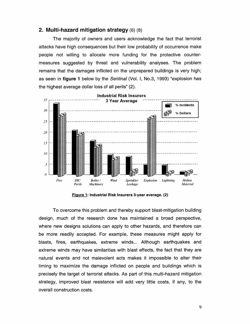
2. Multi-hazard mitigation strategy (6) (8)The majority of owners and users acknowledge the fact that terrorist
attacks have high consequences but their low probability of occurrence make
people not willing to allocate more funding for the protective counter-
measures suggested by threat and vulnerability analyses. The problem
remains that the damages inflicted on the unprepared buildings is very high;
as seen in figure 1 below by the Sentinal (Vol. 1, No.3, 1993) "explosion has
the highest average dollar loss of all perils" (2).
Industrial Risk Insurers35 -------------------- ~~----- 3 Year Average -------- -- ~~----- ~
% incidents30 -.. .--- ------...... -. -........ -------_ ----..... --.. -- --. - - % D ollars
20 --- - - - - ---- -- ------------------------- -- -- - - - - - - - - -
0
Fire DIC Boiler! Wind Sprinkler Explosion Ligktning MoltenPerils Machinery Leakage Material
Figure 1: Industrial Risk Insurers 3-year average. (2)
To overcome this problem and thereby support blast-mitigation building
design, much of the research done has maintained a broad perspective,
where new designs solutions can apply to other hazards, and therefore can
be more readily accepted. For example, these measures might apply for
blasts, fires, earthquakes, extreme winds... Although earthquakes and
extreme winds may have similarities with blast effects, the fact that they are
natural events and not malevolent acts makes it impossible to alter their
timing to maximize the damage inflicted on people and buildings which is
precisely the target of terrorist attacks. As part of this multi-hazard mitigation
strategy, improved blast resistance will add very little costs, if any, to the
overall construction costs.
9
3. Explosions
A. Commercial Vs Military Structures (2)
For years, military facilities have been designed to resist blast attacks
and their focus was to sustain the structure for the purpose of maintaining its
mission. In contrast to that, commercial buildings will be designed only to
saves lives, and there will be no concern for saving the structure as a whole;
localized damage will be allowed, but not total failure, to permit the rescue
teams to evacuate the victims. The overall collapse of the structure usually
causes a lot more deaths than the blast itself.
A lot of care must be taken when designing terrorist-resistant buildings
because people are not willing to live or even work in bunker-like buildings.
Keeping this in mind, we want our site to be as secure as possible; some
parameters that directly influence the impact of an exterior blast are the keep-
out distance and the degree on fenestration (number and size of windows).
Obviously, the architectural and structural features of the building will be the
key parameters in determining how our structure will respond to the blast
loading. Before dealing with all these parameters, a good understanding of
how bombs are categorized is essential for design purposes.
B. Blast loads (2) (9)
An explosion is a rapid release of stored energy; there are many
different types of explosive devices, including TNT (Trinitrotoluene), C-4,
Semtex, and Ammonium Nitrate & Fuel Oil (ANFO). To standardize the
criteria, explosive devices have had their charge-weight scaled to an
equivalent amount of TNT.
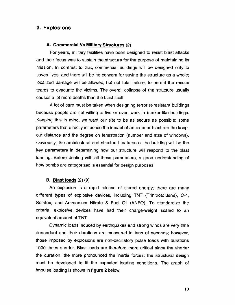
Dynamic loads induced by earthquakes and strong winds are very time
dependent and their durations are measured in tens of seconds; however,
those imposed by explosions are non-oscillatory pulse loads with durations
1000 times shorter. Blast loads are therefore more critical since the shorter
the duration, the more pronounced the inertia forces; the structural design
must be developed to fit the expected loading conditions. The graph of
Impulse loading is shown in figure 2 below.
10
3000
2500 -Peok Presisure, psi 2900
2000
CL1500
1000
500
0*
-500
10 1.5 2.0 2.5 3.0 3.5 4.0 4.5 5.0
Time, ms
Figure 2: Graph of Impulse loading. (9)
A blast can be thought of as a large wave that goes over and around
the building, but the two most important elements defining the threat of a
bomb are its charge weight or size and the distance between the bomb and
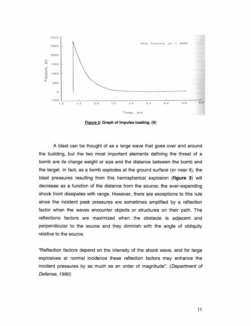
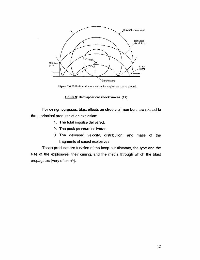
the target. In fact, as a bomb explodes at the ground surface (or near it), the
blast pressures resulting from this hemispherical explosion (figure 3) will
decrease as a function of the distance from the source; the ever-expanding
shock front dissipates with range. However, there are exceptions to this rule
since the incident peak pressures are sometimes amplified by a reflection
factor when the waves encounter objects or structures on their path. The
reflections factors are maximized when the obstacle is adjacent and
perpendicular to the source and they diminish with the angle of obliquity
relative to the source.
"Reflection factors depend on the intensity of the shock wave, and for large
explosives at normal incidence these reflection factors may enhance the
incident pressures by as much as an order of magnitude". (Department of
Defense, 1990)
11
Incident shock front
Reflectedshock front
Charge//T riplepoint Mach
A stem
Ground zero
Figure 2.6 Reflection of shock waves for explosions above ground,
Figure 3: Hemispherical shock waves. (12)
For design purposes, blast effects on structural members are related to
three principal products of an explosion:
1. The total impulse delivered.
2. The peak pressure delivered.
3. The delivered velocity, distribution, and mass of the
fragments of cased explosives.
These products are function of the keep-out distance, the type and the
size of the explosives, their casing, and the media through which the blast
propagates (very often air).
12
4. Architectural Considerations
A. Keep-out distance (2) (3)
This first mode of protection consists of creating a minimum distance
between the explosion and our structure; since no matter what the bomb size
is, the damage will be less severe the further the target is from the source.
When charges are situated extremely close to the target, a highly impulsive
loading will be imposed: a high intensity pressure load over a localized region
of the structure. However, when the same charge is situated further away, the
waves will impose a lower-intensity and longer duration uniform pressure-
distribution over the entire structure. Figure 4 below shows the attenuation of
the impulse loading with standoff distance.
2
[-Charge Standoffloft
40ft
E-ds 4 80 ft
Fi r 4 Ef..s..d d .n b ......ssr. . ()
.~ .... =- T ..
-100 -80 -60 -40 -X 0 20 40 60 80 100Distance from Charge Center Line, ft
Figure 4-2. Typical Plot of the Effect of Standoff on the Spatial Distributionof Peak Reflected Pressure (from the Detonation of 2,000 lb of HighExplosive at Standoffs of 10, 40, and 80 ft)
Figure 4: Effect of standoff distance on blast pressures. (9)
13
The first and most efficient safety measure is the passive protection of
our site. In fact, the strategic placement of the building, its parking lot, gates
and trees to reduce traffic volume and speed usually lead to the most
economical solution. Engineering solutions have to be reasonably cost-
effective, while security solutions must be effective without interfering with the
project's operation. As a rule of thumb, counterterrorism measures will
definitely cost less when considered early in the design phase of a project.
Primarily, good site planning will create a protective perimeter around
our building. Stand-out distances vary by facility, location and threat; they may
be reduced if vehicular access is restricted for example, and if the building
has an optimized surveillance capability around the site. In urban areas, the
required standoff distances are often unrealistic; they are therefore combined
with devices such as plaza setbacks or landscaping (figure 5), to restrict
vehicular access. In order to reduce the risk on our structure and protect its
assets, daily routines as well as maintenance personnel of building facilities
should be modified and the security forces should often be changed.
Figure 5: Planters used to increase the standoff distance.
14
"The more there are layers of protection between attacker and target, the less
appealing the target. External barriers, either camouflaged as part of the
landscaping or introduced as bold statements of defense, may be sufficient to
deter attacks." (2)
B. Security
1) Requirements (2) (3)
For internal explosions, i.e. a device placed inside the building, the
stand-off distance becomes zero and consequently, greater damage and a lot
more injuries will be caused than if the same device was deployed outside the
building. This is the main reason why an access control system should be
implemented, minimizing the opportunity of explosives being introduced into a
building.
Although the main lobby of the building should get most of our
attention, all building penetrations are possible points for security breaches.
Security in the lobby should be managed by its guards that will be equipped
with screening equipment as well as metal detectors. Visible presence of
closed-circuit TV cameras will make it hard for the criminals to succeed and
they will increase the likelihood of them being recognized and apprehended
on the spot or later on; or they might even discourage them of even trying...
Identity card systems should also be implemented to keep visitors out of
restricted areas and to monitor who goes in and out of the building. What
should be kept in mind is that no protective measures will stop the most
determined criminals that are often convinced of the sanity and the purpose of
their crimes. Some might be actually motivated by the challenge of attacking a
well guarded building. Figure 6 shows a photograph of the lobby of a secured
building.
15
Figure 6: Lobby security.
Security measures around the building should be carefully designed
since they are the first line of defense against an attack, keeping the terrorists
as far as possible from the building. Some of these measures include
barricades, sliding gates, rising beams and bollards.
2) Rising barricades (7)
The first security measure that could be used is rising-barricades which
are used to control the flow of vehicles but are also equipped for emergency
situations to stop and disable a fast moving vehicle. In fact, strong barricades
could withstand collisions with huge vehicles (more than 15,000lbs) going as
fast as 75mph. The barricades can usually be lowered using a hydraulic or
pneumatic system; they are usually equipped with emergency backup
systems maintaining the site secure at all times. Barricades are usually made
of heavy steel welded plates which are all mounted above grade and are
therefore being rotated. Upon impact, the forces shall be first absorbed by the
barricade assembly and then transmitted to the foundation of the unit. The
16
removable portion of the barricade will be fastened with bolts which have their
heads below the roadway level.
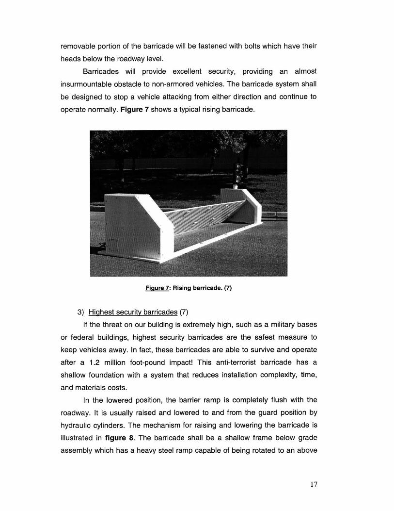
Barricades will provide excellent security, providing an almost
insurmountable obstacle to non-armored vehicles. The barricade system shall
be designed to stop a vehicle attacking from either direction and continue to
operate normally. Figure 7 shows a typical rising barricade.
Figure 7: Rising barricade. (7)
3) Highest security barricades (7)
If the threat on our building is extremely high, such as a military bases
or federal buildings, highest security barricades are the safest measure to
keep vehicles away. In fact, these barricades are able to survive and operate
after a 1.2 million foot-pound impact! This anti-terrorist barricade has a
shallow foundation with a system that reduces installation complexity, time,
and materials costs.
In the lowered position, the barrier ramp is completely flush with the
roadway. It is usually raised and lowered to and from the guard position by
hydraulic cylinders. The mechanism for raising and lowering the barricade is
illustrated in figure 8. The barricade shall be a shallow frame below grade
assembly which has a heavy steel ramp capable of being rotated to an above
17
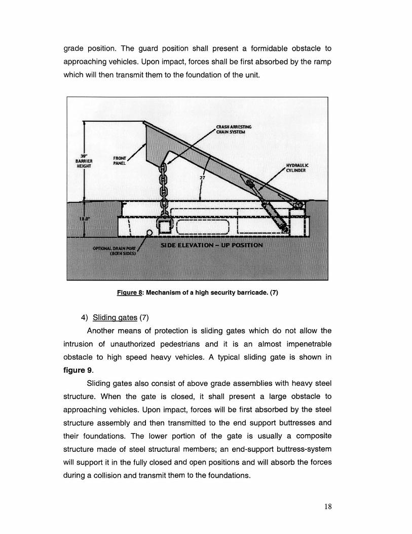
grade position. The guard position shall present a formidable obstacle to
approaching vehicles. Upon impact, forces shall be first absorbed by the ramp
which will then transmit them to the foundation of the unit.
Figure 8: Mechanism of a high security barricade. (7)
4) Sliding gates (7)
Another means of protection is sliding gates which do not allow the
intrusion of unauthorized pedestrians and it is an almost impenetrable
obstacle to high speed heavy vehicles. A typical sliding gate is shown in
figure 9.
Sliding gates also consist of above grade assemblies with heavy steel
structure. When the gate is closed, it shall present a large obstacle to
approaching vehicles. Upon impact, forces will be first absorbed by the steel
structure assembly and then transmitted to the end support buttresses and
their foundations. The lower portion of the gate is usually a composite
structure made of steel structural members; an end-support buttress-system
will support it in the fully closed and open positions and will absorb the forces
during a collision and transmit them to the foundations.
18
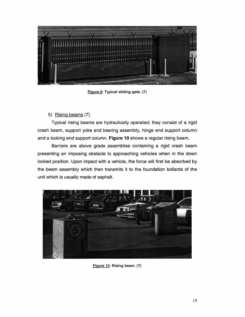
Figure 9: Typical sliding gate. (7)
5) Rising beams (7)
Typical rising beams are hydraulically operated; they consist of a rigid
crash beam, support yoke and bearing assembly, hinge end support column
and a locking end support column. Figure 10 shows a regular rising beam.
Barriers are above grade assemblies containing a rigid crash beam
presenting an imposing obstacle to approaching vehicles when in the down
locked position. Upon impact with a vehicle, the force will first be absorbed by
the beam assembly which then transmits it to the foundation bollards of the
unit which is usually made of asphalt.
Figure 10: Rising beam. (7)
19
6) Bollards (7)
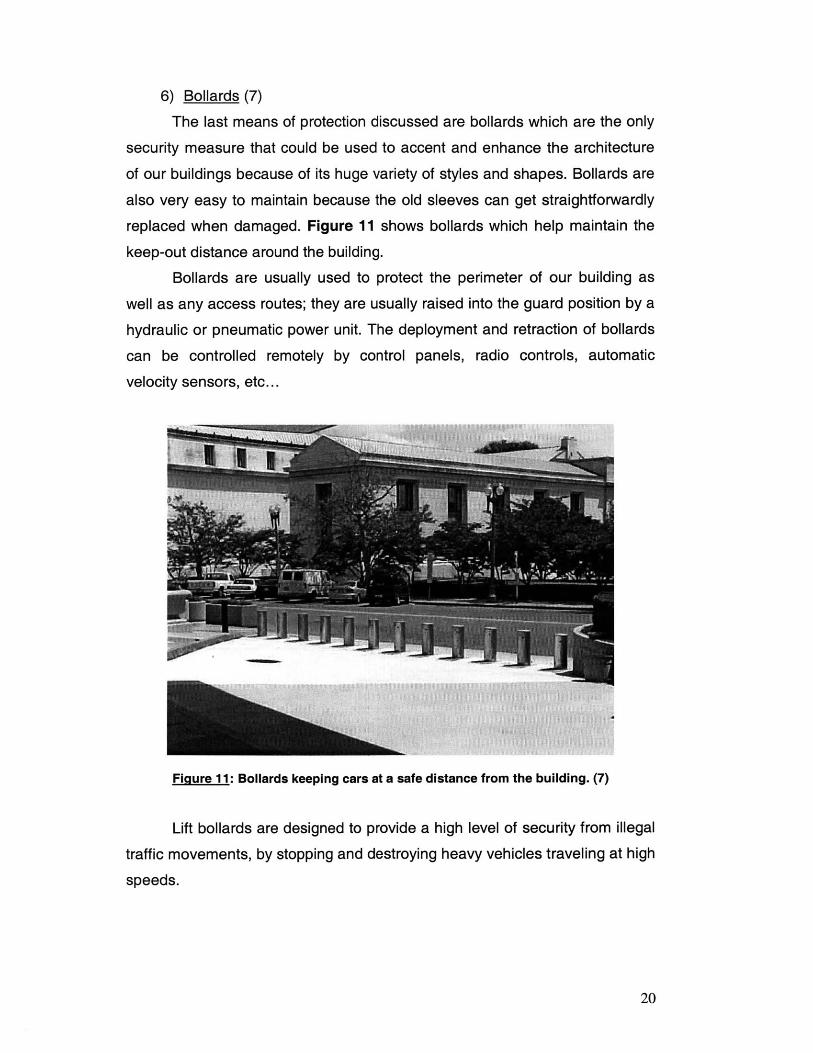
The last means of protection discussed are bollards which are the only
security measure that could be used to accent and enhance the architecture
of our buildings because of its huge variety of styles and shapes. Bollards are
also very easy to maintain because the old sleeves can get straightforwardly
replaced when damaged. Figure 11 shows bollards which help maintain the
keep-out distance around the building.
Bollards are usually used to protect the perimeter of our building as
well as any access routes; they are usually raised into the guard position by a
hydraulic or pneumatic power unit. The deployment and retraction of bollards
can be controlled remotely by control panels, radio controls, automatic
velocity sensors, etc...
Figure 11: Bollards keeping cars at a safe distance from the building. (7)
Lift bollards are designed to provide a high level of security from illegal
traffic movements, by stopping and destroying heavy vehicles traveling at high
speeds.
20
The bollard-system will in fact destroy the front suspension system of
cars, their steering linkage, engine crank case and portions of the drive train
which will result in the loss of steering capacity and forward propulsion.
The bollard is a below grade assembly which consists of a foundation
structure to which the heavy steel cylinder can be lowered. The guard position
presents an obstacle to vehicles; upon impact, forces will be first absorbed by
the cylinder which will then transmit it to the foundation of the unit. The
underside of the Bollard is usually made of an asphalt emulsion coated for
corrosion protection.
C. The building's exterior
1) The fagade (2) (11)
A very delicate balance must be achieved between protecting people's
lives and their property and providing a pleasant living/working environment.
The architectural requirements of most of the buildings call for glass windows
around the first floor. Severe damage will happen to the structural elements
and the connections of the lower floors unless this area is constructed in cast-
in-place reinforced concrete, instead of block walls or curtain walls.
At small standoff distances:
"To protect against a lower charge weight, a nominal 12in thick wall with 0.3%
of steel doubly reinforced in both directions might be required.
For Intermediate charge weight protection, an 18in thick wall with 0.5% steel
might be needed.
Finally, a large charge weight at small standoffs will likely breach any
reasonably sized wall at the lower levels. Therefore precautions have to be
taken and adjustments made for the design of the entire structure."
(2) By M. Ettouney, R. Smilowitz and T. Rittenhouse.
If ornamentation is to be used for the inner facade, lightweight
materials such as wood or plastic are likely to cause less lethal injuries than
brick or metal for example.
21
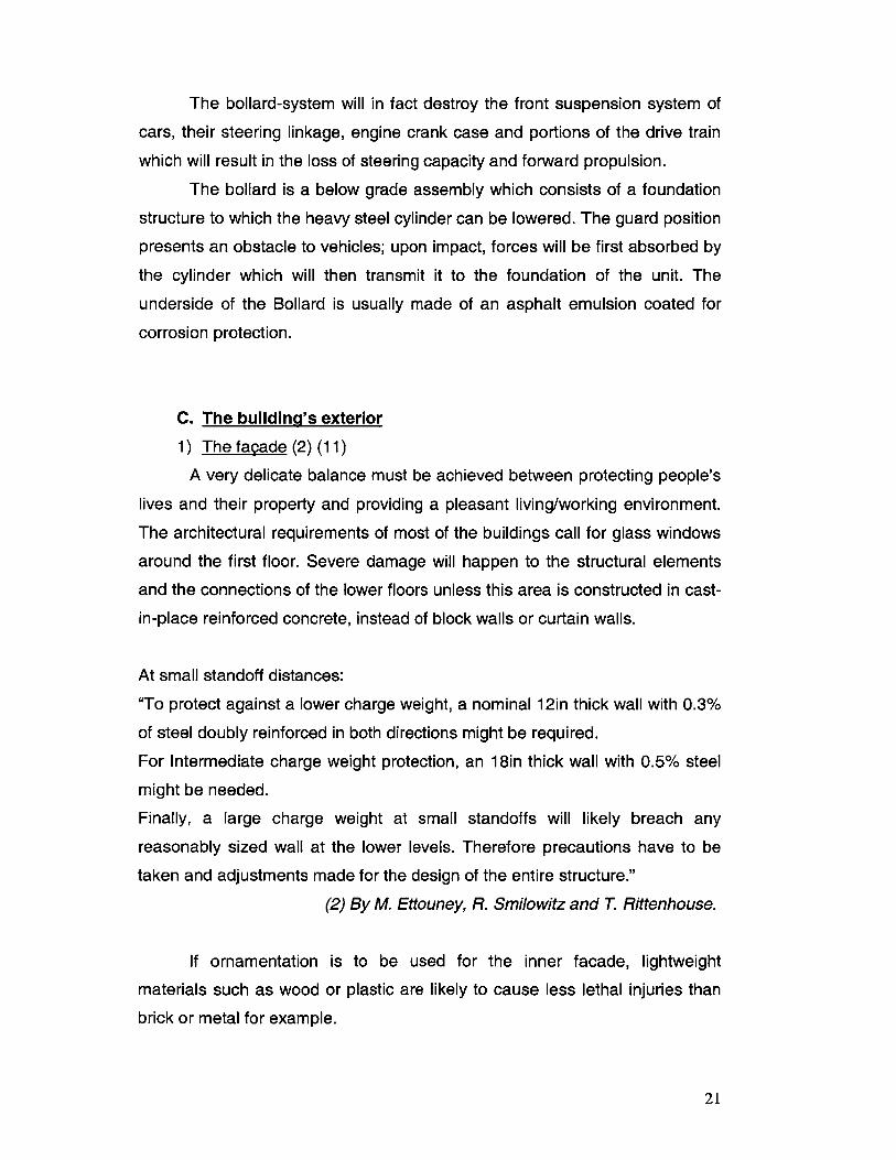
2) Windows (2) (3) (9)
The weakest links of the exterior of buildings are the glass windows. In
fact, these pressure sensitive elements will be the first to fail in response to an
explosion. The commonly used annealed glass behaves very poorly when
loaded dynamically and its failure will produce large sharp-edged flying shards
very similar to knives and daggers. As a matter of fact, the majority of the
injuries of the Oklahoma City bombing of 1995 were caused by flying glass.
As the windows will fail easily, the waves of the blast will enter the building
causing more damage and injury. There is a direct correlation between the
degree of fenestration (openings in the facade) and the amount of blast waves
allowed to enter the structure: as we decrease the amount of fenestration, we
will limit the blast effects. For example, fenestration is limited to 15% in
embassies; however, this number does not apply to modern office buildings
that request an open feeling and proper lighting. Figure 12 shows the
damage to a building's regular glazing after an explosion.
Figure 12: Glass damage on building after an explosion. (11)
22
Typical anneal glass can only resist low blast pressures, so in order to
limit the amounts of flying shards, we could reduce the number and size of
windows or use blast-resistant glazing. In fact, small windows will generally
fail at higher pressures than larger windows making them less prone to
breakage. The fact remains that windows, once the sole responsibility of the
architect, have become a structural issue for the design of blast resistant
buildings.
There are many types of blast-resistant windows which will solve the
problem of flying shards:
1. Composite windows use layers of different glass types and
thermoplastic coatings in specially designed frames. The total
thickness of the window will depend on the security
requirements.
2. Bullet resistant windows have many layers of glass and plastic
bonded together to stop a projectile. In fact, the outer layer
(sacrificial) will break into large pieces of glass which will remain
bonded to a polycarbonate pane; many similar layers will create
a barrier strong enough to resist prolonged physical attacks.
3. Monolithic thermally tempered glass will resist blast loads
because the material used is much stronger than normal glass
and the pane of glass used is massive; this will easily resist a
transient impulse load.
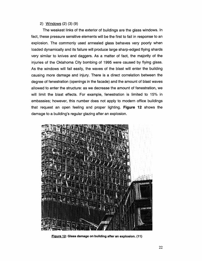
4. Polyester coating films can be applied on the inner face of
regular glass windows; its self-adhesive face will hold the glass
together after its failure. Also, in case the blast was strong
enough to blow the entire pane out of its frame, the projectile will
travel a shorter distance than individual glass fragments,
causing fewer injuries and less damage to sensitive equipment
inside the building; figure 13 compares the trajectories of the
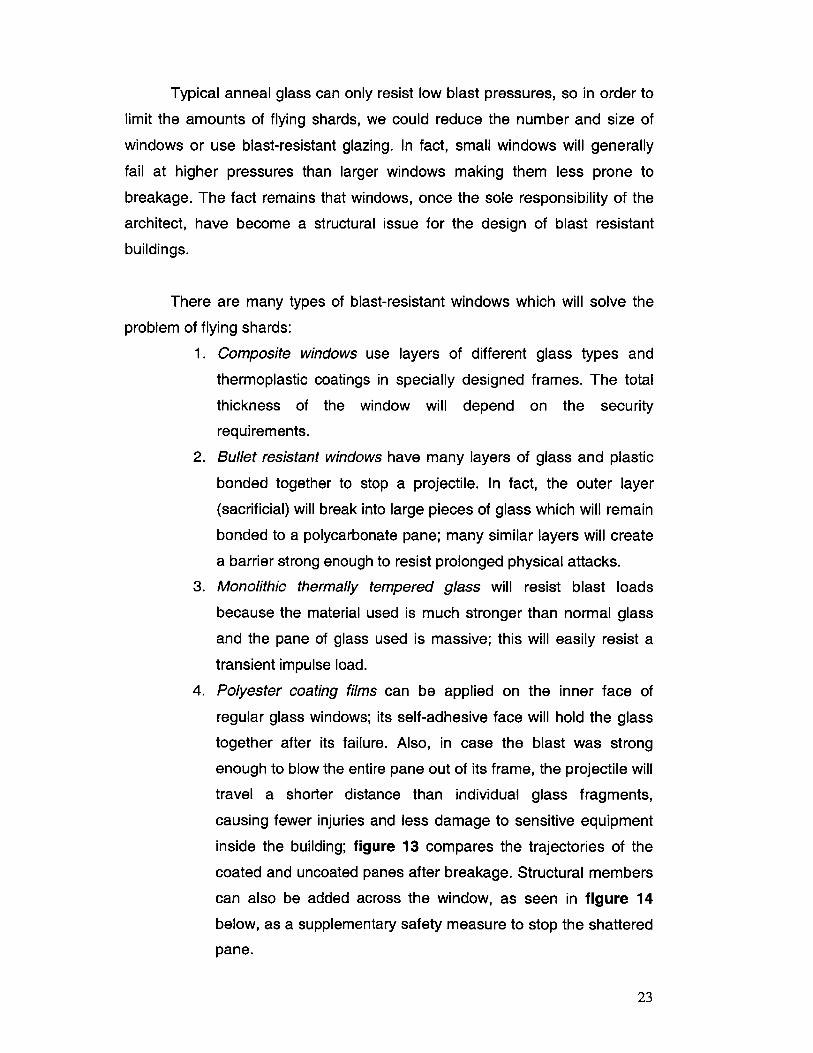
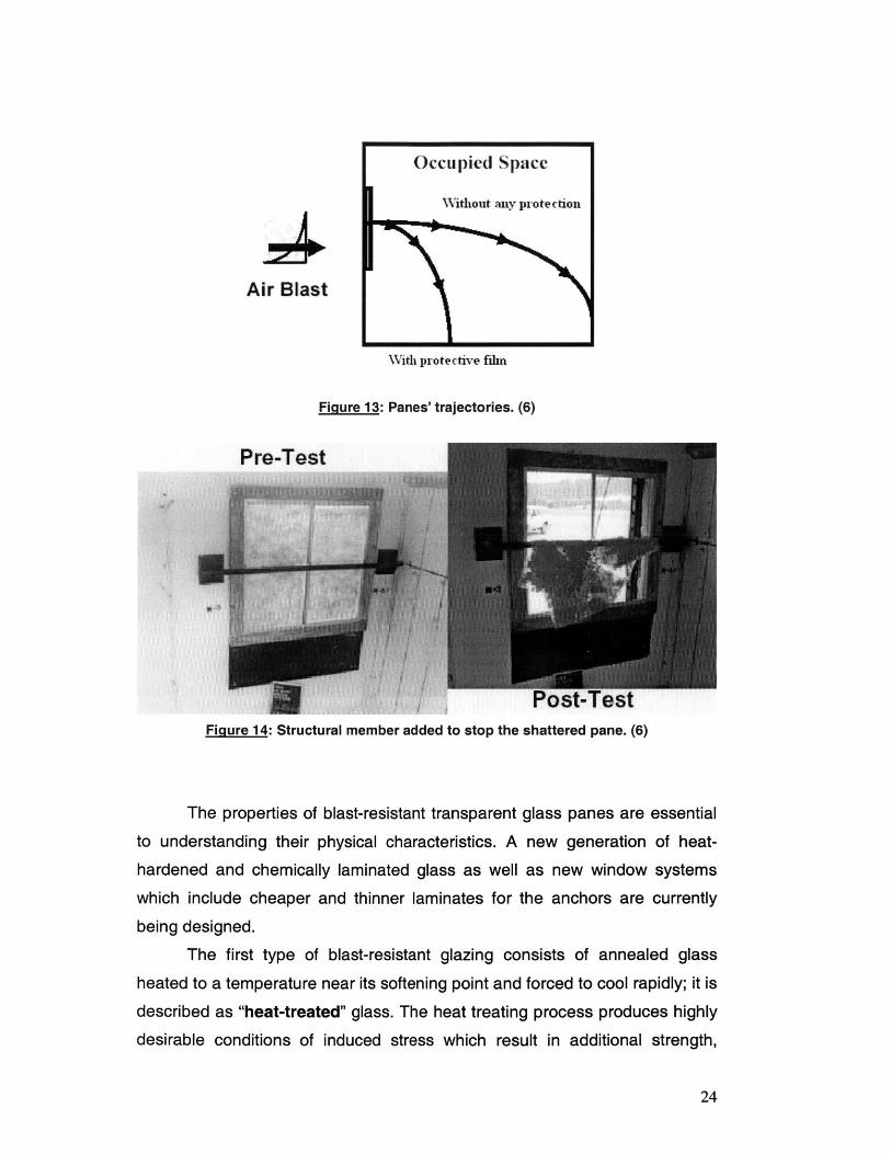
coated and uncoated panes after breakage. Structural members
can also be added across the window, as seen in figure 14
below, as a supplementary safety measure to stop the shattered
pane.
23
Occupied Space
4ithout any pro
Air Blast
WXith protective fihn
Figure 13: Panes' trajectories. (6)
Figure 14: Structural member added to stop the shattered pane. (6)
The properties of blast-resistant transparent glass panes are essential
to understanding their physical characteristics. A new generation of heat-
hardened and chemically laminated glass as well as new window systems
which include cheaper and thinner laminates for the anchors are currently
being designed.
The first type of blast-resistant glazing consists of annealed glass
heated to a temperature near its softening point and forced to cool rapidly; it is
described as "heat-treated" glass. The heat treating process produces highly
desirable conditions of induced stress which result in additional strength,
24
tection
resistance to thermal stress, and impact resistance. This glazing can be
categorized as:
" Fully tempered having a surface compression of at least 10,000
psi, it fractures into small, relatively harmless fragments. This
phenomenon reduces considerably the likelihood of injury to
people, as there are no sharp shards. (Used for the side and
rear windows of cars)
* Heat strengthened: having a surface compression between
3,500 and 10,000 psi, the fracture characteristics of heat-
strengthened glass vary widely from very much like annealed
glass near the 3,500 psi level to similar to fully tempered glass
at the 10,000 psi level.
The second type consists of "chemically tempered" (alkaline) glass
which draws its strength from pre-compression of its outer skin. In some
cases, chemically tempered glass can achieve very high levels of surface
compression: up to 45,000 psi, but their cost is not competitive at all
compared to all other blast resistant glazing.
The third and last type under consideration is a thermoplastic glazing:
"Polycarbonate". This glazing is very difficult to break, and therefore often
required to be equipped with a pop-out system for emergency cases. Its major
problem is that it burns when exposed to open flames releasing carbon
monoxide and carbon dioxide; however not generating the dangerous gases
associated with the burning of plastics such as Cyanide and Chloride. Also,
polycarbonate degrades when exposed to ultraviolet (UV) radiation and has a
thermal expansion coefficient 10 times larger than that of regular glass. To
solve these problems, urethane inter-laminar materials are used to permit
relative motion due to its expansion and typical annealed glass is usually used
as an exterior layer providing UV resistance; the large shards produced by the
annealed glass will be held in place by the polycarbonate which will provide
the blast pressure resistance. (Polycarbonate is used for the windshields of
cars)
25
The direct costs as well as the maintenance costs associated with blast
resistant glazing are extremely high. It is unlikely for a window to survive a
terrorist attack; therefore, it might be wiser to allocate most of our blast-
construction funds on structural upgrade in order for the structure to keep
standing rather than securing the windows.
What is equally important to the design of the glass is the design of its
attachments that are supposed to hold the window long enough for the failure
stresses to develop on the surface of its pane. If the attachments fail before
the window itself, the latter will dislodge intact causing serious injuries and
damage. In order for the window assembly to behave properly, the glazing,
mullions and anchorage must all be capable of transmitting the load to the
surrounding structures. As the pressures on the windows increase, the
exterior wall's size will dramatically increase too.
Frame elements for blast-resistant windows should be able to hold the
full static capacity of the glazing. If the frame deflects excessively, higher
principal tensile stresses will be induced in the pane and the total available
strain energy to resist the blast waves will be reduced.
"Permissible frame deflections are limited to 1/23 0 1h of the supporting span for
Thermally Tempered Glass (TTG) and 1/1 0 0 th of the supporting span for
polycarbonate and glass/polycarbonate layered systems."
(9) Meyers 1984, Keenan et al. 1986, Department of State 1990
Frame elements should also be designed to withstand the actual
dynamic capacity edge shears transmitted by the blast-resistant glazing. The
edge shears will be determined from the magnitude and duration of the
applied load, the resistance of the glazing and finally, the inertia effects of the
plate (calculated from the deflected shape of the plate). The frame will be
analyzed for this combined loading.
26
D. Doors (9)
For internal threats, doors are the weakest links, both in the structural
counter-blast design and the security design; therefore, they should be
carefully designed to provide sufficient safety in our structure. Doors can be
divided into two categories: commercial doors (personnel and equipment),
and vault doors. Common personnel doors are usually made of hollow steel
panels that can be reinforced with vertical channels, and filled with a
noncombustible core. Personnel security doors are sometimes used as an
external barrier and they are often made as a one-way secured entryway.
Equipment doors however, can be corrugated metal roll-up doors, solid-panel
sliding doors and rigid-panel overhead-type door. Unlike the very secure vault
doors which are used in mercantile or banks vaults, commercial doors can
easily be defeated with the appropriate tools and do not withstand any blast
effects.
The design of doors to stop burglars or even terrorists with tools will not
be covered in this paper; only a brief overview of blast effects on doors will be
exposed. In fact, an explosive charge that is not in close proximity of the door
will produce a uniform pressure which the door should be able to resist if
properly designed. The materials most commonly used are reinforced
concrete or solid steel; and the door sections are designed to resist the total
pressure applied by blast waves as well as to stop the progression of fire as
well as blocking the flying shrapnel. The supports of the door are as important
as the door itself; frames and hinges should be carefully designed to
withstand blast pressures in both directions (direction of the opening and
closing of the door); the supports should resist at least as much as the total
flexural resistance of the door's panel.
E. Securing appliances (2) (3) (9)
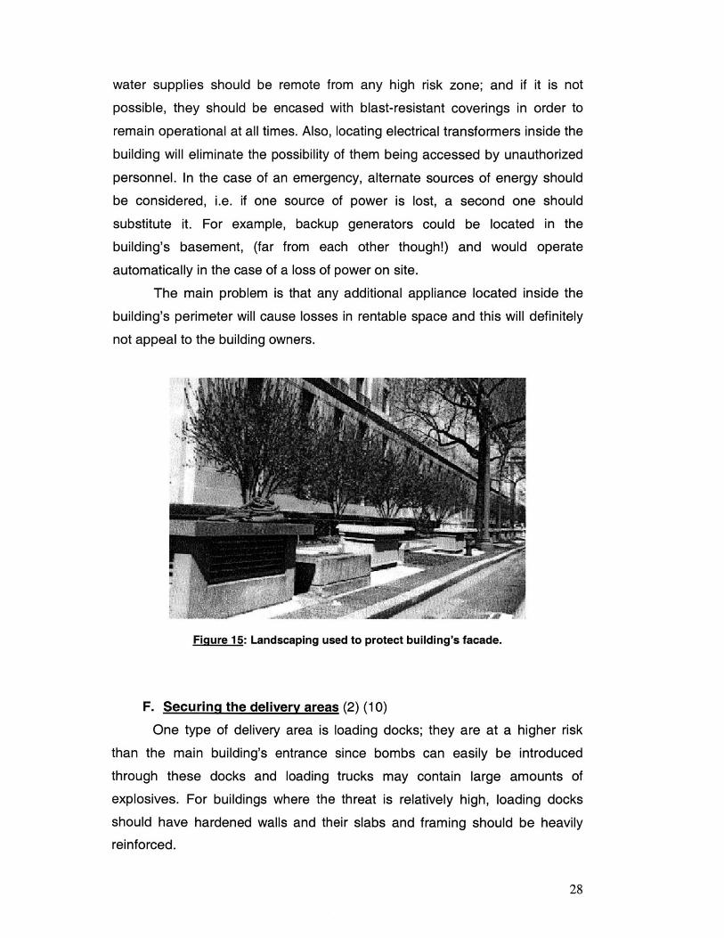
Trees can improve protection by obscuring assets (figure 15) and
people; in fact, surveillance cameras can be discretely mounted on them to
screen perpetrators. Communication systems are also important assets and
should be protected by locking manholes and monitoring underground
tunnels. As a general rule, building services such as gas, fuel, power and
27
water supplies should be remote from any high risk zone; and if it is not
possible, they should be encased with blast-resistant coverings in order to
remain operational at all times. Also, locating electrical transformers inside the
building will eliminate the possibility of them being accessed by unauthorized
personnel. In the case of an emergency, alternate sources of energy should
be considered, i.e. if one source of power is lost, a second one should
substitute it. For example, backup generators could be located in the
building's basement, (far from each other though!) and would operate
automatically in the case of a loss of power on site.
The main problem is that any additional appliance located inside the
building's perimeter will cause losses in rentable space and this will definitely
not appeal to the building owners.
Figure 15: Landscaping used to protect building's facade.
F. Securing the delivery areas (2) (10)
One type of delivery area is loading docks; they are at a higher risk
than the main building's entrance since bombs can easily be introduced
through these docks and loading trucks may contain large amounts of
explosives. For buildings where the threat is relatively high, loading docks
should have hardened walls and their slabs and framing should be heavily
reinforced.
28
Their location is a critical parameter; they should be placed away from
electrical appliances, power and fuel lines, and most importantly away from
critical life safety systems such as fire command and emergency systems. A
good ventilation system should also be provided in case of a blast. (Mail
rooms and receiving areas should be dealt with in the same manner). In high
risk buildings, such locations should be located in a remote location,
preferably off site even if it incurs more costs and inconveniences.
G. Parking Facilities (2) (3)
Parking lots located outside the building perimeter have to be secured
to guarantee the required keep-out distance from the face of the structure.
Also, street parking should not be allowed on the side of the street next to the
building; the authorities might have to be compensated for that since the city
gains a lot of money from street parking. In addition, depending on the
approval of city officials, one lane of traffic (along the building's perimeter)
could be removed and changed into an extended side-walk.
For the design of an underground parking garage located below the
building, the concern is the progressive collapse in the event of a car's
explosion. The design of the parking garage should be dealt with very
carefully and all structural considerations detailed in the next section should
be taken into account; emergency ventilation is also prudent. If an
underground garage must be used, a space next to the building should be
considered rather than just below the building.
Obviously, the parking lot should be eliminated but this happens to be
very unpractical especially because of the lack of parking spaces especially in
major cities such as New York City and Boston. Where parking cannot be
excluded, the number of spaces should be limited to the tenants only, and
depending on the threat assessed, parking security should be equipped with
machine readable identifiers, vehicle-weight sensors and spot checks should
often be performed.
29

H. Choosing materials (4) (5) (11)
The blast loads have a very short duration and a high intensity, so the
ductility and the natural period of our structure are going to govern its
response. As a rule of thumb, tall buildings have lower natural frequencies
therefore longer natural periods than short buildings. Individual structural
elements such as beams and columns might have their response time
approaching the loading duration; this is the main reason why ductile
elements will be safer in the case of an attack. In fact, ductile members made
of steel or reinforced concrete will absorb a lot of strain energy before
breaking and therefore can undergo substantial bending; however, brittle
elements made of glass, brick, wood, or cast-iron for example will fail abruptly
without going through any deformation.
Concrete is the most widely used construction material, and its most
important property when designing impact resistant structures is its
compressive strength. However, when concrete is exposed to blasts, spalling
and fragmentation will occur; but this may be reduced if internal
reinforcements are added to increase the strength and fracture toughness of
the concrete or if fiber-reinforcements are applied on its surface. Typical
reinforcements include steel bars or wires, fiberglass, carbon, and other
polymer materials. Polymer materials (relatively inexpensive) sprayed on the
surface of concrete will hold fragments together although the concrete might
undergo severe cracking.
Metals are also very commonly used as construction materials; they
include steels, aluminum alloys and titanium. Metals are highly useful in
protecting structures against explosions because of their inherent strength,
toughness and energy absorption capability. They are also useful in designs
due to their relatively low cost and flexibility in modifying their characteristics:
ductility, strength... For example, a higher ductility will allow a greater
deformation of the metal thus permitting the penetrating shrapnel to proceed
farther through it. In addition, some metals have high impact strengths, which
are indicators of their toughness and resilience to fracture when hit by a
projectile and also their ability to sustain multiple hits. Another very important
30
characteristic when considering sustained loads is fracture toughness which
determines how resistant a metal is to crack propagation; high hardness
metals are poor structural materials because they are more susceptible to a
brittle fracture; conversely, lower hardness metals have good structural
qualities, but are not as effective in resisting fragment penetration. A good
balance must be found to pick the adequate material.
Of the majority of metals used, steel has the greatest resistance to
penetration, but at the expense of added weight to the application; Titanium
however provides very good resistance at a much lower density than steel but
at a premium price; finally, Aluminum alloys usually require a much greater
thickness to attain a comparable penetration resistance to that of steel and
Titanium.
A new set of construction materials being used are composites. One
example of composite materials is the Polymer Matrix Composite (PMC) that
combines the beneficial properties of both polymer resins (ability to absorb
and mitigate kinetic energy) and high performance fibers (high to ultrahigh
modulus of elasticity). High performance composites possess higher specific
strengths (ultimate tensile strength divided by density) than metals, and they
are capable of providing equivalent blast resistance at reduced weights.
Polymer matrix composites commonly used are fiberglass (lowest cost),
aramid fiber, and polyethylene fiber composites.
Thermosets, however, are matrix resins used in conjunction with fiber
materials; they are easier to process, they have higher operating
temperatures, and are more chemically resistant, but are more susceptible to
cracking, and are toxic in their uncured state. Epoxy resins are generally used
for the best energy absorption properties while phenolic resins are used for
fire, smoke and toxicity resistance. Layered composite back-plates utilizing
epoxy and phenolic materials are used in some cases to combine the
beneficial properties of both resins. Because many of these composite
materials can be expensive to apply in structural protection, with judicious
selection and design, they may be applied in a very cost effective manner in
selecting critical areas where performance criteria demand them.
31
The last type of materials discussed is ceramics. In fact, ceramic
armor materials are used for the containment of blast fragments and bullet
penetrations; they offer the advantage of weight reduction as well as higher
impact energy absorption than the majority of metals. Unlike metals that
absorb kinetic energy through plastic deformation, ceramics absorb the
energy through fracture; any protection scheme utilizing ceramics must
therefore use backing plates providing structural support during the impact
event; these backing plates can be made of metal, polymers, or composites.
Tiles are used to limit the fracture area, and thin coverings also prevent flying
ceramic shards.
The most common ceramic materials used for armor applications are
Alumina (A1203 which is the cheapest), Boron Carbide (B4C), Silicon Carbide
(SiC), and Titanium Diboride (TiB2).
In addition, the use of materials withstanding extreme heat will mitigate
the risk that shattered pieces will become shrapnel. For example, sheeting
made of flame-retardant composite material such as gypsum will retard the
spread of fire. Also, high performance steel has higher resistance against
impact and heat; and a new form of lighter and stronger concrete is being
developed to reduce the total weight of structures and gain space. The use of
both steel and concrete in beams (steel beams reinforced in concrete not
reinforced concrete beams) will add more protection in the case of a
prolonged fire; a delicate balance between the amount of steel and concrete
has to be achieved.
"Steel is strong but can bend under intense temperatures. Concrete holds up
longer against heat, but can crack and break under extreme temperatures."
Klemencic (5)
32
I. Choosing shapes (10) (11)
Concerning the architectural shapes of our structure, high-mass and
long span elements such as beams and slabs are relatively flexible
components. On the other hand, rigid, short span and light-weight elements
are very poor energy absorbers which will fail catastrophically.
The response of the structure (as a whole entity) will depend not only
on the materials used, but with the way, these materials are used too. In fact,
a concrete building could be built as a flexible frame or a much more rigid,
fortress-like structure. Obviously, massive structures will behave better than
those of lightweight construction. More importantly, structures with re-entrant
corners (U or L shaped) should be avoided since blast effects will be
magnified; these corners will cause pressures to build up. Typically,
symmetrical buildings will have the best behavior when subjected to blast
loadings.
J. HVAC systems (3) (9)
In the event of an explosion, a lot of equipment from the buildings'
interior, such as false ceilings, Venetian blinds (better to use curtains),
ductwork and air conditioners, might become airborne. Heavy equipment such
as air-conditioners should be placed closer to the floor rather than the ceiling
since they might cause serious injuries if explosions detach them.
The major issue concerning ventilation for a building remains the
placement of air intakes, since the biological threat is one of the most serious
ones. Securing air intake for high rise buildings is relatively easy; vents should
be located at least 50 to 60 feet high to prevent toxic materials released at the
ground level from entering the Heating Ventilating and Air Conditioning
(HVAC) of the building. Common practice is to place these intakes on the roof
and concealing them, making it a lot harder for terrorists to contaminate the
air supplies; however, these intakes cannot be left unattended. They should
be guarded and secured against contaminants; a security camera kept
operational at all times should be mounted on the roof to monitor any
unauthorized access.
33
In case of a fire inside the building, HVAC systems should be designed
in such a way not to permit the smoke to migrate to the rest of the building.
The main lobby and delivery areas should have dedicated supply and return
HVAC systems, independent of the rest of the building because of the higher
risks in these areas. Taking the security of HVAC systems to the next level
would consist of adding negatively pressured ducts which would suck toxic
agents into a filtering system; but this would come at very high costs since
units will have to be oversized to get enough flow in and out of the building
(because of the small size of the openings of the biological filters).
K. Firefighting Systems (3)
The combustible contents of buildings should be kept to a minimum to
prevent fires from starting and spreading. Also, the building should be sited far
enough from neighboring buildings to provide maximum separation; the use of
incombustible roofs, exterior walls and fire protected structural systems will
reduce the threat of ignition from adjacent burning buildings.
The use of fire detectors and automatic sprinklers has become
mandatory for the vast majority of buildings; these buildings are therefore
equipped with their own fire pump room. For high risk buildings, it is more
cautious to have two separate fire pump rooms located far from each other
and redundant sprinkler systems. The designers must weigh the costs of
these redundancies against the chance that their firefighting system will be
destroyed during an attack.
For the case of an emergency, the building should be equipped with
graphical circulation patterns as well as exit signage. Also, emergency
stairways should be added and made wider to accommodate heavier foot
traffic; and they should definitely not end in the building lobby but outside the
facility. Redundant fire alarm systems can be provided without a big increase
in cost, and the use of multiple speaker currents will ensure that the coverage
remains if one of the electric circuits is damaged by the explosion. Finally, fire
command centers should be monitored during all hours of the day to ensure
the maximum safety for the building's inhabitants.
34
If our building is monitored by security cameras, the control rooms
where the video storage tapes are located should be hardened with fireproof
materials since the tapes will definitely be helpful during investigations and
more importantly, they will serve as a "learning" tool. In order to satisfy their
fire code requirements, some countries such as the United Kingdom, Hong
Kong and Canada provide separate elevators for firemen. These high speed
elevators are relatively small (accommodating not more than 3 to 4 firemen)
and they exit into pressurized vestibules equipped with communication
equipment and hose racks.
35
5. Structural Considerations
A. General (2) (8) (9)
The advantage of increasing the standoff distance of a building will be
limited by the charge weight of the bomb. If the charge weight is small,
standoff distance will significantly affect the threat; however, if the charge
weight is large, the blast forces may demolish the structure despite the
maximization of standoff distance, therefore not helping with the survivability
of the building's occupants. In order for the damage to remain localized and
prevent the overall collapse of the building, structural improvements should be
implemented in the design of various members of our structure: atriums,
slabs, columns, beams, walls ...
Costs are often the major driver in construction; however bearing in
mind that the total cost of the structural frame is about 15 to 20% of the total
building costs, the required structural upgrade to meet with blast-engineering
requirements may result in an increase of no more than 2 to 3% overall.
Compared to the estimated damage incurred in the case of an attack, this
increase is relatively negligible.
The major driver for a successful blast protection is designing
redundancies into the structure to carry the additional loads imposed by an
explosion. In fact, structural members should be designed to carry additional
loads such as if one member is severely damaged to the point it cannot
function anymore, the load path will change and the load will be evenly
distributed to its neighboring members.
B. Atriums (2)
In order to give impressive function spaces and balcony elevator
lobbies, atriums are commonly used in prestigious buildings and hotels.
These atriums will bring natural light inside the building; however, the broken
windows after a blast will give the appearance of extensive damage and many
internal structural elements will be exposed to blast waves. The major
problem in the case of atriums is the multiple reflections of the waves that will
36
increase damage and injuries. When atriums are extensive, i.e. providing a
significant open space relative to the overall size of the structure, blast
pressures could split the building apart, causing major damage.
The exterior wall of the atrium should therefore be reinforced and the
glass and its framings should be strengthened to withstand small to medium
charges. Also on the inside, all structural members of the atrium should be
strengthened to support the pressures of the reflected blast waves; these
members include balcony parapets, spandrel beams as well as exposed
slabs.
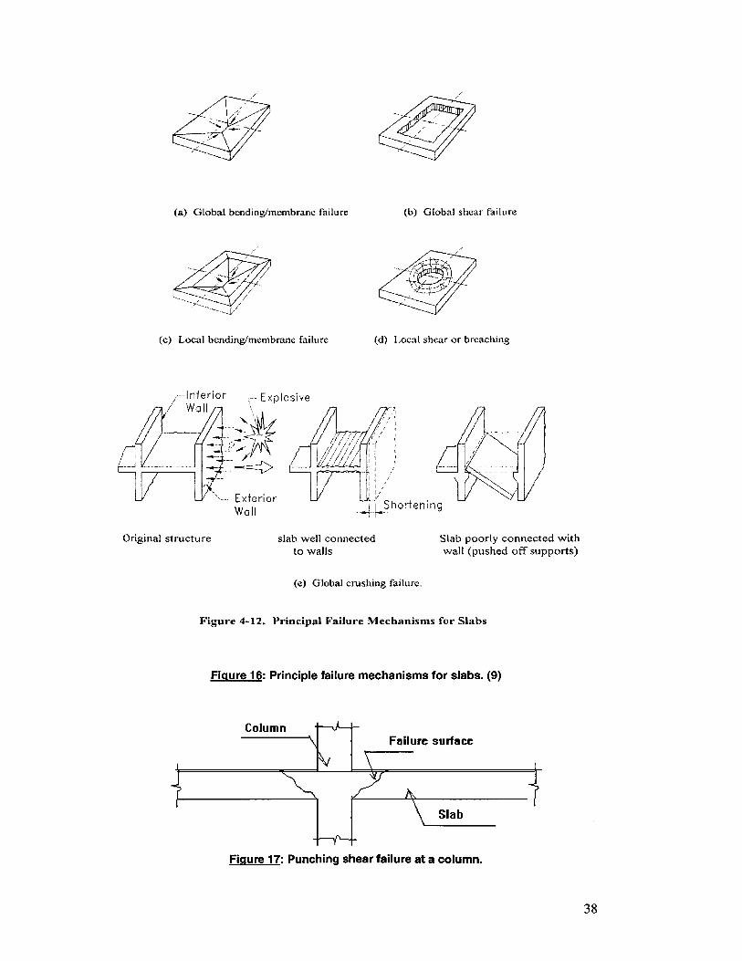
C. Slabs (2) (9)
The most commonly used floor slabs are reinforced concrete flat plate
structural systems; they provide the most economical solution along with the
maximum use of vertical space. Usually, as the building is designed, drop
panels and column capitals are not required to satisfy the loading
requirements; therefore, the thickness of the slab remains relatively the same
since live load requirements are typical throughout the building. When the
slab is subjected to a dynamic loading, the ability of the slab to transfer forces
to the walls and columns can severely diminish, as the moment-resisting
capacity at the columns and walls is lost. As illustrated in figure 16 below,
failure can be of different types:
1. The slab might experience localized failure.
2. Also shown in figure 17 below, punching shear failure could
occur which will increase the unsupported length of the columns
and probably buckling of these columns.
3. Crushing failure is due to an excessive load transmitted from the
edges of the slab. For well connected slabs, failure will only be
local; however, for slabs with inadequate connections
catastrophic failure might occur. The whole building might lose
its lateral stability if the lateral load transfer system consisting of
shear walls, columns and slabs is weakened enough.
37
(a) Globa bend] ng/membrane failure
(c) Local bending/membrane failure
(b) Global shear failure
(d) Local shear or breaching
-rlerior -Explosive
Wall
ExteriorWall Shortening
Original structure slab well connectedto walls
Slab poorly connected withwall (pushed off supports)
(e) Global crushing failure.
Figure 4-12. Principal Failure Mechanisms for Stabs
Figure 16: Principle failure mechanisms for slabs. (9)
Failure surface
Slab
Figure 17: Punching shear failure at a column.
38
Column
4- -- (I-- -
To provide the necessary precautions against a blast, the following
improvements should be implemented early in the design phase:
" Detailed design of the lower floors of a building should be very
thorough since they are the most susceptible to encounter large
blast pressures.
" Also in the lower floors, column capitals and drop panels should
be provided to reduce the effective slab length as well as to
improve the resistance against punching shear failure.
" Although not mandatory, spandrel beams should be included to
enhance the response of the slab edge.
" The slab-column connections should be heavily reinforced and
closed-hoop stirrups should be properly anchored around
flexural bars for additional safety.
" Beams should be included over critical sections of the slab; this
will greatly enhance the transmission of lateral loads to the
shear wall.
" Bottom reinforcement should be provided continuously through
the connection with the columns to prevent brittle failure; for the
extreme case where the column has punched through the slab,
this reinforcement will allow the shear transfer mechanism not to
be inhibited.
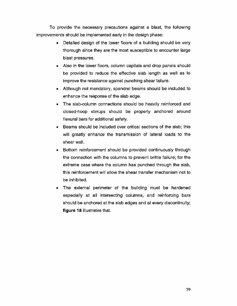
" The external perimeter of the building must be hardened
especially at all intersecting columns, and reinforcing bars
should be anchored at the slab edges and at every discontinuity;
figure 18 illustrates that.
39
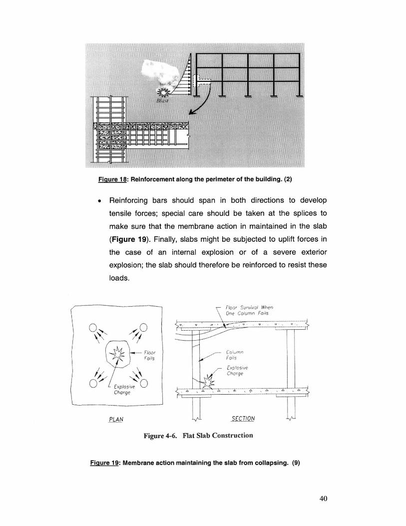
Figure 18: Reinforcement along the perimeter of the building. (2)
Reinforcing bars should span in both directions to develop
tensile forces; special care should be taken at the splices to
make sure that the membrane action in maintained in the slab
(Figure 19). Finally, slabs might be subjected to uplift forces in
the case of an internal explosion or of a severe exterior
explosion; the slab should therefore be reinforced to resist these
loads.
ON0 -- Floor
ExposiveCharge
PLAN
Floor SovwolF henColumn Foil
S7
E x P!osfveChcrge
-_ C--Q_
Figure 4-6. Flat Slab Construction
Figure 19: Membrane action maintaining the slab from collapsing. (9)
40
If the majority of these guidelines are carefully followed, the slab should
be able to act as a safety net for the damaged structure; even in the case of
punching shear failure, no progressive collapse should develop. Although
slabs without good connections or enough ductility will behave poorly,
providing large amounts of lethal debris, they could stop the propagation of
the blast waves.
Slab deformations interact will blast waves to relieve the pressure on
structures; this was the main driver of researchers at Weidlinger Associates
who are suggesting retrofitting the slabs with openings, deliberately increasing
their frangibility; this venting will equalize the pressures applied to the slabs.
D. Columns (2) (9)
In typical structures, columns are designed to resist gravity loads, and
ductility is not taken into account as a major parameter. This is definitely not
the case for blast-resistant design since columns will be subjected to severe
bending in the case they are directly exposed to blast waves; ductility will
therefore become a major parameter for the combined effect of the axial loads
due to gravity and to the lateral displacement due to the blast waves.
In order for the damage to our structure to remain localized, these are
some recommendations to improve the columns' responses:
* The lower floors' columns as well as the perimeter columns
should receive somewhat more attention since they are more
liable to encounter blast waves; they should be designed with
adequate ductility for bending requirements, as well as
maximum strength for blast pressures and impact of flying
debris. To achieve added ductility and strength, these columns
could be encased in steel jackets for example or steel columns
could be embedded in reinforced concrete columns or wall
sections.
" As slabs may be subjected to uplift forces, tensile forces might
briefly develop and the combined effect of bending and tension
41
might damage the column considerably. For this worse case
scenario, the columns could be reinforced to handle a transient
tensile force.
* Finally, spiral reinforcement will greatly enhance the lateral
response of columns in case of a blast by confining its core.
Again, following one or more of these guidelines will improve
significantly the blast-resistant mechanism of columns. Redundancy is very
critical for columns to prevent the overall collapse of our structure since the
loss of a lower floor column can effectively damage neighboring columns; thus
with a "domino" effect, the localized damage will propagate into overall
collapse.
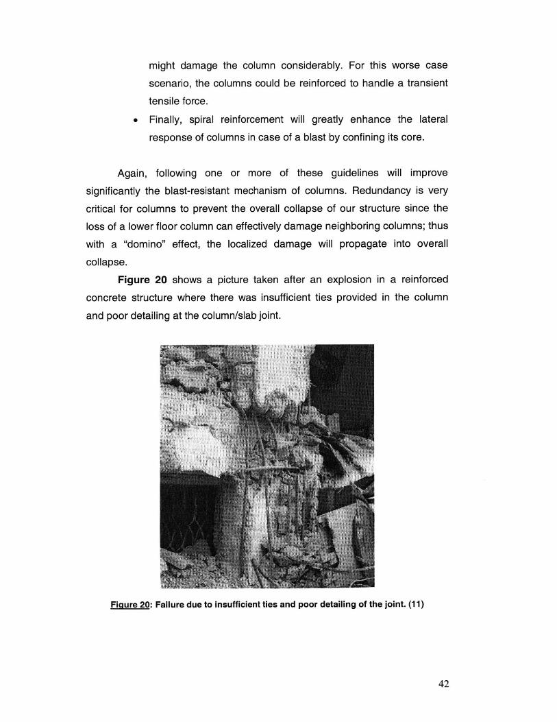
Figure 20 shows a picture taken after an explosion in a reinforced
concrete structure where there was insufficient ties provided in the column
and poor detailing at the column/slab joint.
Figure 20: Failure due to insufficient ties and poor detailing of the joint. (11)
42
E. Beams (9)
Just like column and slabs, the beams should be properly detailed:
development lengths, bar laps, ties and splices and the materials used are
reinforced concrete or steel. The only failure types considered will be those
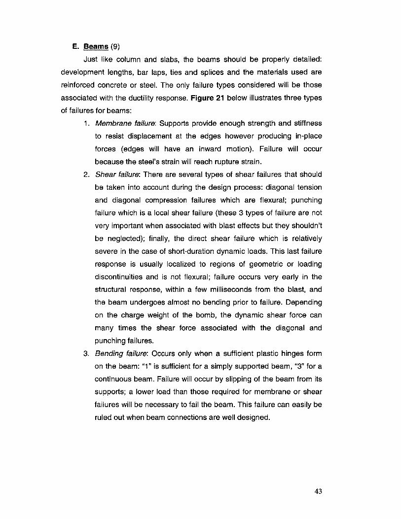
associated with the ductility response. Figure 21 below illustrates three types
of failures for beams:
1. Membrane failure: Supports provide enough strength and stiffness
to resist displacement at the edges however producing in-place
forces (edges will have an inward motion). Failure will occur
because the steel's strain will reach rupture strain.
2. Shear failure: There are several types of shear failures that should
be taken into account during the design process: diagonal tension
and diagonal compression failures which are flexural; punching
failure which is a local shear failure (these 3 types of failure are not
very important when associated with blast effects but they shouldn't
be neglected); finally, the direct shear failure which is relatively
severe in the case of short-duration dynamic loads. This last failure
response is usually localized to regions of geometric or loading
discontinuities and is not flexural; failure occurs very early in the
structural response, within a few milliseconds from the blast, and
the beam undergoes almost no bending prior to failure. Depending
on the charge weight of the bomb, the dynamic shear force can
many times the shear force associated with the diagonal and
punching failures.
3. Bending failure: Occurs only when a sufficient plastic hinges form
on the beam: "1" is sufficient for a simply supported beam, "3" for a
continuous beam. Failure will occur by slipping of the beam from its
supports; a lower load than those required for membrane or shear
failures will be necessary to fail the beam. This failure can easily be
ruled out when beam connections are well designed.
43
BEND1NGM MEBRANE FAILUR.
SHEAR FAILURE
END/NC FAILURE (CAN OCCUR QNLY, F SUPPORT OR CONNECTIONS FA _L)
Figure 21: Bending failure types. (9)
F. Load-Bearing Walls (9)
Walls cannot sustain the combined effect of axial and bending loads.
This unstable behavior produces a secondary moment caused by the axial
force due to the bending-induced lateral deflection, which enhances the lateral
deflection causing collapse of the wall.
Usually buildings having load-bearing walls have cast-in place
reinforced concrete walls or reinforced masonry walls. In fact, masonry
structures have serious blast-resistance limitations for obvious reasons and
their use is not desirable. Also, pre-cast concrete construction is not
recommended because connection joints will be very difficult to design to
satisfy requirements for both strength and ductility.
44
In order to satisfy the safety requirements for load-bearing walls,
reinforcing bars should be continuous into the slab elements as well as in the
wall above. For added safety, bar splices should be kept away from the
construction joints because heavy debris from the concrete cover might
detach after an explosion and the lap splices might fail, cutting the
reinforcement and therefore losing the stability.
G. Lateral Shear Resisting Walls (2)
The effect of blast loads is more critical than this of seismic loads since
seismic motion is applied over the entire foundation system of the building;
blast loads have higher intensities and are concentrated over a smaller
region. The total base shear applied in both cases could be the same, but the
lateral resisting behavior is definitely not.
In order for our shear walls to resist these localized high-impulse
loadings, the slabs, columns and joists should be carefully detailed for ductility
of the system, especially for reinforced concrete. The structure will have to
deform substantially under extreme loadings and it will absorb large amounts
of energy.
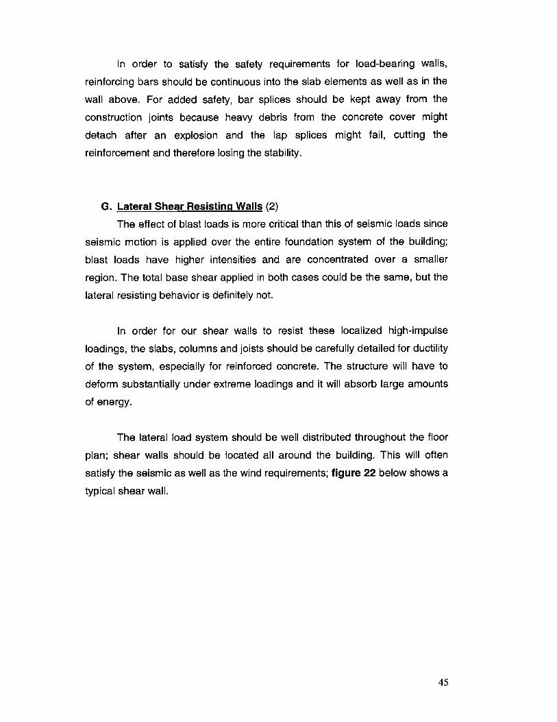
The lateral load system should be well distributed throughout the floor
plan; shear walls should be located all around the building. This will often
satisfy the seismic as well as the wind requirements; figure 22 below shows a
typical shear wall.
45
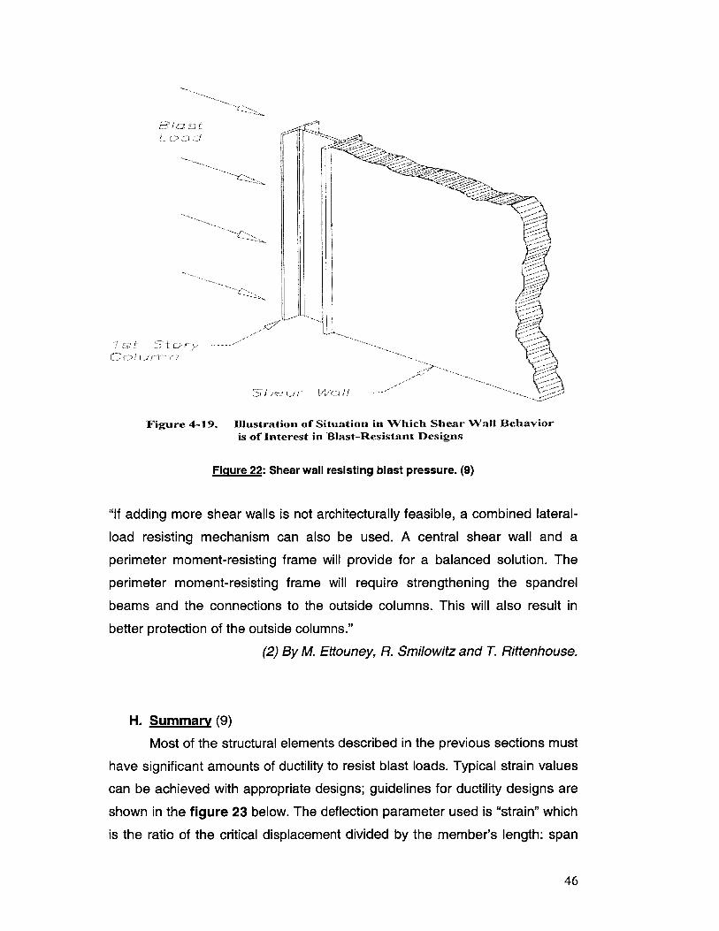
Figure 4-19.
;/- gr i" (:_
Illustration of Situation in Which Shear Wall Behavioris of Interest in Blast-Resistant Designs
Figure 22: Shear wall resisting blast pressure. (9)
"If adding more shear walls is not architecturally feasible, a combined lateral-
load resisting mechanism can also be used. A central shear wall and a
perimeter moment-resisting frame will provide for a balanced solution. The
perimeter moment-resisting frame will require strengthening the spandrel
beams and the connections to the outside columns. This will also result in
better protection of the outside columns."
(2) By M. Ettouney, R. Smilowitz and T. Rittenhouse.
H. Summary (9)
Most of the structural elements described in the previous sections must
have significant amounts of ductility to resist blast loads. Typical strain values
can be achieved with appropriate designs; guidelines for ductility designs are
shown in the figure 23 below. The deflection parameter used is "strain" which
is the ratio of the critical displacement divided by the member's length: span
46
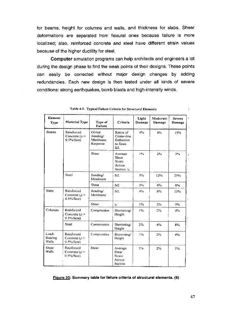
for beams, height for columns and walls, and thickness for slabs. Shear
deformations are separated from flexural ones because failure is more
localized; also, reinforced concrete and steel have different strain values
because of the higher ductility for steel.
Computer simulation programs can help architects and engineers a lot
during the design phase to find the weak points of their designs. These points
can easily be corrected without major design changes by adding
redundancies. Each new design is then tested under all kinds of severe
conditions: strong earthquakes, bomb blasts and high-intensity winds.
Table 4-2. Typical Failure Criteria for Structural Elements
Element Light Moderate Severe
Type Material Type Type of Criteria Damage Damage DamageFailure
Beams Reinforced Global Ratios of 4% 8% 15%Concrete (p > Bending/ Center-line0.5%/face) Membrane Deflection
Response to Span,5/Li
Shear Average 1% 2% 3%ShearStrainAcrossSection,;
Steel Bending/ 6/Li 5% 12% 25%Membrane
Shear 5/L 2% 4% 8%
Slabs Reinforced Bending! 61L 4% 8% 15%
Concrete (p > Membrane0. 5%/face) ______
Shear y, 1% 2% 3%
Columns Reinforced Compression Shortening/ 1% 2% 4%Concrete (p > Height0.5%/face)
Steel Compression Shortening/ 2% 4% 8%Height
Load- Reinforced Compression Shortening/ 1% 2% 4%Bearing Concrete (p > HeightWalls 0.5%/face)
Shear Reinforced Shear Average 1% 2% 3%Walls Concrete (p > Shear
0.5%/face) StrainAcrossSection
Figure 23: Summary table for failure criteria of structural elements. (9)
47
6. Existing buildings (2) (5) (9) (11)
For existing buildings, the first step also consists of assessing the
potential threats of exposure to attacks; then, the most important step consists
of evaluating the vulnerability of the structures, which is a difficult and inexact
approach compared to new designs. The critical components in the structure
should be identified and their capacity should be determined relative to their
required resistance; most of the building codes are more stringent than they
used to be and significant upgrades have to be done for resisting blast effects.
Options should eventually be identified for upgrading the structure; conceptual
designs as well as cost estimates will therefore be developed. Finally, the
optimal design based on technical feasibility and cost effectiveness will be
selected.
Usually, retrofitting is the best solution to meet the new security
standards; for example, for reinforced concrete buildings, the most adequate
method consists of wrapping the concrete with carbon fiber jackets such as
Fiber Reinforced Polymer (FRP) jackets that improve its ductility, shear
capacity and augment its flexural strength; steel jackets can also be used for
reinforcing columns. For a more exact science, one or more of these general
guidelines should be followed to enhance the response of existing buildings to
terrorist attacks: (guidelines that differ from those elaborated in the structural
upgrade part will be discussed only)
* Mass increase: An increase in mass of a component will have a
positive effect to overcome impulse loading. Because mass
added in a member will increase the dead load on its supporting
components, their strength will have to increase too.
* Increased strength: It can be achieved by increasing the yield
strength (ay) of materials or by changing the cross-section of
members; selecting of either of these two methods depends on
the materials used and the type of problems encountered. For
example, wood should obviously undergo an increase in
section; reinforced concrete should also have an increase in
48
section size if plastic response is considered as the higher
damage category; for steel, an increase in ay will reduce ductility
but will not affect rotation, however an increase in strength will
stiffen the member; but the best solution for steel remains
increasing the section depth which has the greatest effect on
rotation, the most critical parameter.
" Boundary conditions modifications: for example changing a two-
side supported wall into a three-side supported system will
effectively allow it to sustain more loads before undergoing full
plastic response. An alternate load path will also be created
increasing the redundancy of the structure.
" Reduction in span length: stiffness changes will occur because
members in reinforced concrete or steel will have significant
plastic deformation at the higher damage levels.
Concerning the glazing in existing buildings, the majority of owners
prefer installing polyester film coatings which is a relatively inexpensive retrofit
solution compared to laminated glazing which provides more resistance but
involves replacing every window in the building. Coatings on the inside face of
the window will hold the shards together after failure. A new British innovation
is blast curtains; it consists of translucent curtains that will hold the glass
shrapnel although permitting the blast waves to go through.
Protective measures are always limited by practical considerations,
such as the budget, the space available or by the limits of available
technology. The major budget issue for the installation of improvements, such
as new elements in blast-resistant or fire-resistant materials for example, in a
building could cost up to 10 more times the original cost of construction.
49
Conclusion (3) (10)
Any structure which may be considered as a potential terrorist target
should have periodic threat and vulnerability assessments; and new courses
of action should be undertaken if new technologies are developed. Other
major concerns which are often neglected are the emergency operations and
the planning for disasters; these two areas can potentially save many lives. In
fact, practice drills should be conducted every once in a while and the
emergency procedures should be regularly reviewed since they are essential
components of an emergency plan.
Buildings are not the only potential targets of terrorist groups; every
mode of transportation is at risk too. For example, bridges are potential
targets because of their symbolic significance and trains because they can be
easily derailed causing a large number of casualties. For the future,
concerned parties are evaluating safety measures for major transportation
routes: redundancy in roads to keep a region functional in case of an
emergency; two bridges (two crossings) instead of one bridge with many
lanes; the ports are upgrading their security with "gamma" ray detection of
containers and their main concern will move from drugs to weapons; finally,
new airports will have blast resistant parking lots and the setback distance will
be increased to 300 feet for terminals and the open areas surrounding the
airport will be secured to guarantee that planes will not be shot down during
take-off or landing.
Finally, the dissemination of public information on projects is a growing
concern; for example, public access to the design plans of a bridge can
potentially be very dangerous since its single most vulnerable point can easily
be identified. In fact, many companies are now removing sensitive information
from their websites.
50
References
1) Mechanical Engineering Magazine, September 2002 issue, "Designing
for Sabotage" by Emily M. Smith.
2) Weidlinger Associates website: httP://www. wai. com.
3) Engineering News Record, March 2 5th 2002 issue, "Building for a
Secure Future".
4) Material Ease #20, Department of Defense, by R. Lane, B. Craig and
W. Babcock.
5) Abcnews, "Engineering against Disaster", website:
http://abcnews.go.com September 28th 2001.
6) Protecting People and Buildings from Terrorism, National Research
Council, 2000 + CD-ROM.
7) Delta Scientific Corporation website: http://www.deltascientific.com/
8) Making Buildings Safer for people, by A. Nowak and T. Galambos,
1990.
9) Structural Design for Physical Security, American Society of Civil
Engineers, 1999.
10)Protecting Buildings from Bomb Damage, National Research Council,
1995.
1 1)Blast Effects on Buildings, G. C. Mays and P. D. Smith, 1995.
12) Explosive Loadings of Engineering Structures, P. S. Bulson, 1997.
51