Embed Size (px)
Citation preview

Circular Slot Loaded Rectangular Monopole MicrostripAntennas for Multi-band Operation and
Virtual size Reduction M. Veereshappa1 and S.N Mulgi2
1Department of Electronics, L.V.D.College, Raichur: 584 101, Karnataka, INDIAE-mail: [email protected]
2Department of PG Studies and Research in Applied Electronics, Gulbarga University,Gulbarga 585 106, Karnataka, INDIA E-mail: [email protected]
Abstract: This paper presents the design and development of circular slot loaded rectangular monopole microstrip antenna formulti-band operation and virtual size reduction. A circular slot of radius 0.8 cm is placed on the rectangular radiating patch.The antenna operates for seven bands between 1 to 16 GHz and gives a virtual size reduction of 57.66 % with a maximum gainof 10.36 dB. If circular slot is replaced by a circular ring slot of width 0.2 cm on the rectangular patch the seven operatingbands are converted into four bands and antenna gives maximum virtual size reduction of 62 % and gain 11.47 dB withoutchanging the nature of ominidirectional radiation characteristics. The proposed antennas are simple in their design andfabrication and they are use low cost substrate material. Theses antennas may find applications in microwave communicationsystems.
Keywords: Microstrip antenna, monopole, circular slot, ominidirectional, virtual size
Serials Publications, ISSN : 0973-7383I J E E Volume 5 • Number 1 • January-June 2013 pp. 13-16
1. INTRODUCTION
The rapid developments in microwave communicationsystems often demand novel design of microstrip antennaswith compact size, simple in design, low cost and capable ofoperating more than one band of frequencies. Owing to itsthin profile, light weight, low cost, planar configuration andeasy fabrication, the microstrip antenna is the better choicefor these requirements. Number of investigations has beenreported in the literature for dual, triple, and multibandoperation [3-8]. Designs of single feed equilateral triangularmicrostip antennas are obtained with a virtual size reductionup to about 22 % by embedding cross slots on radiatingpatch [9]. A square-ring microstip antenna with truncatedcorners shows 19 % virtual size reduction [10]. DoubleC-slot microstip antenna is designed and simulated to havea gain of 6.46 dBi and gives a virtual size reduction of 37 %[11]. Slotted rectangular microstip antenna has beendesigned to achieve maximum virtual size reduction around50 % [12]. Most of the antennas presented in the literatureare efficient to show maximum virtual size reduction up to 50% with complex structure or bigger in size and also requirecareful manufacturing procedure than that of the regularmicrostrip antenna for practical applications. In this paper asimple technique has been demonstrated to construct themonopole antennas for multi-band operation, large virtualsize reduction and high gain by loading circular slot andcircular ring slot along the center axis of the patch without
changing the nature of ominidirectional radiationcharacteristics. The obtained results are quite good comparedto the literature values.
2. DESIGN OF ANTENNA GEOMETRY
The art work of the proposed antenna is sketched by usingcomputer software Auto-CAD to achieve better accuracyand is fabricated on low cost FR4-epoxy substrate materialof thickness of h = 0.16 cm and permittivity �r = 4.4.
Figure 1 shows the top view geometry of circular slotloaded rectangular microstrip monopole antenna (CSLRMA).In Fig. 1 the area of the substrate is L × W cm. On the topsurface of the substrate a ground plane of height which isequal to the length of microstripline feed Lf is used on eithersides of the microstripline with a gap of 0.1 cm. On the bottomof the substrate a continuous ground copper layer of heightLf is used below the microstripline. The CSLRMA is designedfor 3 GHz of frequency using the equations available for thedesign of conventional rectangular microstrip antenna inthe literature [2]. The length and width of the rectangularpatch are Lp and Wp respectively. The feed arrangementconsists of quarter wave transformer of length Lt and widthWt which is connected as a matching network between thepatch and the microstripline feed of length Lf and width Wf.A semi miniature-A (SMA) connector is used at the tip of themicrostripline feed for feeding the microwave power. Acircular slot of radius 0.8 cm is loaded on rectangular patch.

14
Figure 2 shows the geometry of circular ring slot loadedrectangular monopole microstrip antenna (CRSLRMA). Inthis figure circular ring slot of radius R and width Ws is loadedon the rectangular patch. The feed arrangement of Fig. 2remains same as that of Fig. 1. The design parameters of theproposed antennas is shown in Table 1.
Table 1Designed Parameters of Proposed Antenna
Antenna L W Lp Wp Lf Wf Lt Wt R Ws
parameter
Dimensions 8.0 5.0 2.34 3.04 2.48 0.3 1.24 0.05 0.8 0.2 in cm
Figure 1: Top View Geometry of CSLRMA
Figure 2 Top View Geometry of CRSLRMA
3. EXPERIMENTAL RESULTS
The antenna bandwidth over return loss less than –10 dB istested experimentally on Vector Network Analyzer (Rohde &Schwarz, Germany make ZVK model 1127.8651). The variationof return loss verses frequency of CSLRMA is as shown inFig. 3. From this graph the experimental bandwidth (BW) iscalculated using the equations,
BW = 2 1 100c
f f
f
� ���� �
� �(1)
were, f1 and f2 are the lower and upper cut of frequencies ofthe band respectively when its return loss reaches – 10 dBand fc is the center frequency of the operating band. Fromthis figure, It is seen that, the antenna operates between 1 to16 GHz and gives seven resonant modes at f1 to f7, i.e. at 1.27,4.70, 8.84, 11.19, 12.80, 13.80 and 15.35 GHz. The magnitudeof experimental –10 dB bandwidth measured for BW1 to BW7by using the equation (1) is found to be 50 MHz (4.08 %), 100MHz (2.11 %), 2.65 GHz (31.12 %), 2.26 GHz (20.12 %), 690MHz (5.33 %), 1.32 GHz (9.27 %) and 520 MHz (3.37 %)respectively. The resonant mode at 1.27 GHz is due to thefundamental resonant frequency of the patch and othersmodes are due to the novel geometry of CSLRMA. Thefundamental resonating mode f1 is shifted from designedfrequency 3 GHz to 1.27 GHz which gives a virtual sizereduction of 57.66 %. The antenna gain measured at f2 foundto be 10.36 dB.
Figure 3: Variation of Return Loss Versus Frequencyof CSLRMA
Figure 4 shows the variation of return loss versesfrequency of CRSLRMA. it is seen that, the antenna operatesfor four bands of frequencies. The magnitudes of theseoperating bands at BW8 to BW11 are found to be 188 MHz(15.61 %), 110 MHz (2.31 %), 3.17 GHz (37.44 %) and 5.72 GHz(43.79 %) respectively.
Hence by comparing Fig. 3 and 4, it is clear that theCRSRMA converts seven bands into four bands by mergingof BW3, BW4 of Fig. 3 into BW10 and BW5, BW6 and BW7 of
15
Fig. 3 into BW11. The fundamental resonant frequency of theantenna further shifts from 1.27 GHz to 1.14 GHz. This is dueto the coupling effect of microstripline feed and top groundplane of CRSLRMA. This shift of frequency gives a maximumvirtual size reduction of 62 % and also the antenna givesmaximum gain of 11.47 dB measured at f9 because the resonantfrequency of f2 and f9 remain same in both the cases which isevident from Fig. 3 and 4.
Figure 4: Variation of Return Loss Versus Frequencyof CRSLRMA
Hence it is clear that, the use of circular ring slot inCRSLRMA is quit efficient the widening the operating bandsand the enhancing the virtual size reduction and also gain.
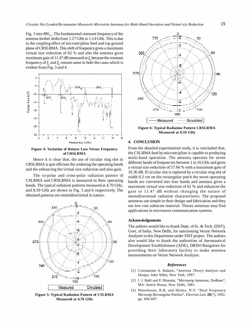
The co-polar and cross-polar radiation pattern ofCSLRMA and CRSLRMA is measured in their operatingbands. The typical radiation patterns measured at 4.70 GHz,and 8.59 GHz are shown in Fig. 5 and 6 respectively. Theobtained patterns are ominidirectional in nature.
Figure 5: Typical Radiation Pattern of CSLRMAMeasured at 4.70 GHz
Figure 6: Typical Radiation Pattern CRSLRMAMeasured at 8.59 GHz
4. CONCLUSION
From the detailed experimental study, it is concluded that,the CSLRMA feed by microstripline is capable to producingmulti-band operation. The antenna operates for sevendifferent bands of frequencies between 1 to 16 GHz and givesa virtual size reduction of 57.66 % with a maximum gain of10.36 dB. If circular slot is replaced by a circular ring slot ofwidth 0.2 cm on the rectangular patch the seven operatingbands are converted into four bands and antenna gives amaximum virtual size reduction of 62 % and enhances thegain to 11.47 dB without changing the nature ofominidirectional radiation characteristics. The proposedantennas use simple in their design and fabrication and theyuse low cost substrate material. Theses antennas may findapplications in microwave communication systems.
Acknowledgements
The authors would like to thank Dept. of Sc. & Tech. (DST),Govt. of India. New Delhi, for sanctioning Vector NetworkAnalyzer to this Department under FIST project. The authorsalso would like to thank the authorities of AeronauticalDevelopment Establishment (ADE), DRDO Bangalore forproviding their laboratory facility to make antennameasurements on Vector Network Analyzer.
References[1] Constantine A. Balanis, “Antenna Theory Analysis and
Design, John Wiley, New York, 1997.
[2] I. J. Bahl and P. Bharatia, “Microstrip Antennas, Dedham”,MA: Artech House, New Delhi, 1981.
[3] Waterhouse, R.B, and Shuley, N.V: “Dual FrequencyMicrostip Rectangular Patches”, Electron Lett, 28(7), 1992,pp. 606-607.

16
[4] W.-C. Liu and H.-J. Liu, “Compact Triple-Band SlottedMonopole Antenna with Asymmetrical CPW Grounds”Electron Lett, 42(15), 2006, pp. 840-842.
[5] K. G. Thomas and M. Sreenivasan, “Compact Triple BandAntenna for WLAN, WiMAX Applications”, Electron Lett.45(16), 2009, pp. 811-813.
[6] C. W. Jung, I. Kim, Y. Kim and Y. E. Kim. “Multiband andMultifeed Antenna for Concurrent Operation Mode”.Electron Lett, 43(11), 2007, pp. 600-602.
[7] Jia- Yi Size, Kin-lu Wong, “Slotted Rectangular MicrostipAntenna for Bandwidth Enhancement”, IEEE Trans Antennasand Propagat 48(8), 2000, pp. 1149-1152.
[8] K. Song, Y. Z. Yin, S. T Fan, Y. Z Wang and L. Zhang, “OpenL-Slot Antenna with Rotated Rectangular Patch forBandwidth Enhancement”, Electron Lett 45(25), 2009,pp.1286-1288.
[9] Gui-Han Lu; Kin-Lu Wong, “Single-Feed Circularly PolarizedEquilateral- Triangular Microstip Antenna with a TuningStub” IEEE Trans on Antennas and Propagat 48(12), 2000,pp. 1869-1872.
[10] Gautam, A.K; Negi, R; Kanaujia, B.K, “Square-Ring Microstipfor CP operation” Antennas and Propagation (APCAP), 2012IEEE Asia-Pacific Conference Proceedings, pp. 263-264.
[11] Tlili,B. “Design of Double C-Slot Microstip Patch Antennafor WiMax Application” Antennas and Propagation SocietyInternational Symposium (APSURSI), 2010 IEEE ConferenceProceedings, pp. 1-4.
[12] Kumar, R.; Malathi, P.; Ganesh, G. “On the Miniaturizationof Printed Rectangular Microstip Antenna for WirelessApplication”. Microwave and Optoelectronics Conference,2007, pp. 334-336.


![Using Self Determination Theory Principles to Promote ...publish.illinois.edu/glherman/files/2016/05/2016-IJEE-IM-Relatedness.pdfcourse design are discussed in other publications [30–34]](https://img.dokumen.tips/doc/110x75/5fa8a10f62b226317a30b9fd/using-self-determination-theory-principles-to-promote-course-design-are-discussed.jpg)


