Embed Size (px)
Citation preview

- J
DR-6 . . Contract NAS8-35614
-s * -
Final Volume I Report June 1987
STS Propellant Scavenging Systems Study - Part II
Executive Summary and Study Results
( U S A - C R - 179275) SZS PBOPELLABT SCJIYEYGItiG ~ a a - i m 16 SYSPEHS STUDY, EdlL6T 2, YCLUBIE I t EXECUTXVVB SDMHBBY AID SfIUDY BESIfLliS Pinal Report (Eartia Barietta derosgace) 114 p CSCL 22B Unclas
63/16 0092674
Y I C H O U D A E R O S P A C E c-
https://ntrs.nasa.gov/search.jsp?R=19880008332 2020-05-01T06:43:26+00:00Z
DR-6 Contract UAS8-35614
Final Report June 1987 Volume I
Executive Summary STS PROPELLANT and Study Results SCAVEUGIUG
SYSTEMS STUDY - PART I1
W T I U MARIETTA MICHOUD AEROSPACE Blew Orleans, Louisiana

. I
FOREWORD
This document is part of the final report of the STS Propellant Scavenging Systems Study, Part If, performed under Contract UAS8-35614. It is a continuation of the propellant scavenging studies documented in a report dated February 1986. The final report was prepared in accordance with DR-6 by Martin Marietta Hichwd Aerospace in Uew
Orleans, Louisiana, for the UASA Marshall Space Flight Center. The report was prepared in two volumes:
Volume Title
I Executive Summary and Study Results
I1 Cost and WBSIDictionary
The W F C Study Manager was Milton A. Page and the Martin Marietta Study Managers were Warren L. Gilmore and Walter P. Haese and the Deputy Study Manager was Kevin J. P. Kelleher. The work was performed under the direction of Frank L. Williams, Director of Advanced Ptograms and
Program Development.
I
ii
. . . .. .. , . :. ' . . . . . . .

COUTEISTS
SECTION TITLE PAGE
1.0 EXECUTIVE S U M I A B Y . . . . . . . . . . . . . . . . . . . . . . . . . . . . . . . . . . . . . . . . . . . . . . . . . 1 1.1 Concept Definition........................... ................. 1
1.2 Life Cycle Cost Analyais ...................................... 2
1.3 Task Results.................................................. 5
1.4 Conclusi ons.................................................... 8
1.5 RecamPenbati~............................. ................... 10
2.0 STUDY BESULTS..................................................... 11 2.0.1 Introducti on................................................. 11
2.0.3 Inclusion of Unmanned Cargo Vehicle......................... 19 2.1 TASK A - Mission Model Update ................................... 25
2.1.1 Preliminary Ground Rules-and STAS Mission Model............. 25
2.1.2 Updated Mission Model....................................... 31
2.1.3 Compatibility of OTV, SDV and STS Models.................... 39
2.1.4 OTV Facility Basing Altitude.............................. ..
2.0.2 Study - Parts I and II...................................... 13
41
2.2 TASK D - Optinam Tank Sizing and Arraneement .................... 2.2.1 Optimum Tank Sizing .........................................
2.2.3 Tank Configuration Selection................................ 49
43
43 2.2.2 Tank Arrangement Options.................................... 46
2.2.4 Self-Propelled Tank Unit.................................... 52
2.3 TASK C - I n t e r f a c e s . . . . . . . . . . . . . . . . . . . . . . . . . . . . . . . . . . . . . . . . . . . . . 56 2.3.1 Ground Interfaces........................................... 57 2.3.2 Flight I n t e r f a c e s . . . . . . . . . . . . . . . . . . . . . . . . . . . . . . . . . . . . . . . . . . . 60
2.3.3 Propellant Conditions....................................... 61
2.4 TASK F - Hardware Descript ion................................... 63 2.4.1 SDV Payload Module.......................................... 64
2.4.2 Tank Sets................................................... 64 2.4.3 Test Plan - Update .......................................... 71
2.5 TASK B - Tank Reuse............................................. 71 2.5.1 Reusability Design Features................................. 73
2.5.2 Tank Sets Required .......................................... 75
iii

COUTmrS
SECTION TITLE PACE I
2.6 TASK G - SDV Impacts ............................................... 76 2.6.1 Ueight Impacts ............................................... 76 2.6.2 Operational Impacts. ........................................ 80
3 . 0 ~ C ~ . . . . . . . . . . . . . . . . . . . . . . . . . . . . . . . . . . . . . . . . . . . . . . . . . . . . . . . . 85
A P P m I X 1: DETNLBD TANK SFT WEICXT B~~S....................... A-1
iv

FIGURES
TITLE PAGE
1.1-1
1.1-2
1.3-1
2.0-1
2.0-2
2.0-3
2.0-4
2.0-5 2.0-6
2.0-7
2.0-8 2.0-9
2.0-10
2.0-11
2.0-12
2.1-1
2.1-2
2.1-3 2.1-4
2.1-5 2.1-6
2.1-7 2.1-8
2.1-9
2.1-10
2.1-11
2.1-12
2.2-1
2.2-2
2.2-3
UCV Reference Mission 'with Self-Propelled Tank Set. ............ 3 Self-Propelled Tank Set - Trhtric View.........;............. . 4
SDV Launches Required to Deliver OTV Propellant ................ 6
Study Histo rp...............................................~.. 11
Concept 6 Propellant: Scavenging Vehicle (PSV).................. 13
Concept 6 Uission Scenario...................-.................. 14
Separation, Docking and Berthing Scenario...................... 16
STS Propellant Scavenging Vehicle Quick Reference Data......... 17
18 Propellant Scavenging vs STS Tanker LCC........................
SDV/UCV Configurati on.......................................... 20
SDV Payload L l o d u l e . . . . . . . . . . . . . . . . . . . . . . . . . . . . . . . . . . . . . . . . . . . . . 21 UCV Reference Mission.......................................... 21
UCV Reference Mission with Propellant Scavengi ng............... 22 Summary Study Plan...................... .......... ............ 23
Study Milestone Schedule....................................... 24
SDV Tankers Required to Supply Space Based OTV Propellant 1995 - 2010.................................................. 27
Propellant Recovered 1995 - 2010............................... 28 OTV Propellant Requirements .................................... 29
Annual SDV Flights Required 1995-2010 to m e t
Civil Mission Llodel - option If, Version 2.0.................... 32 Cargo Profile. Civil Mission Hodel -Version 2.0................. 33 OTV Propellant Requirements - STAS Model Option II.............. 35 OTV Performance - Up.................... ........................ 38
OTV Perfonnance - Down.......................................... 38
Propellant Delivered Per Y e a r . . . . . . . . . . . . . . . . . . . . . . . . . . . . . . . . . . . 39
SDV Launches Required to Deliver OTV Propellant ................. 40
OTV Propellant Delivered by SDV vs Facility Basing Altitude... .. 41
Interaction of ULV Characteristics with Tank Sizing/Arrangement Task......................................... 44 . Tank Dimensions and Capacities .................................. Concept 6 PSV Alternative Installations. ........................
Requirement Trends .................................. :........... 30
45
47
V

FIGURES mmBKR TITLE
2.2-4
2.2-5
2.2-6
SDV with Built-in Tankage ..................................... Fofirard Mounted Tank Set ...................................... A f t Mounted Tank S e t ..........................................
2.2-7
2.2-8
2.3-1
2.3-2 2.3-3
2.3-4
2.4-1
2.4-2
2.4-3
STS/PSV Docking and Berthing Scenario ......................... UCV Reference Mission With Self-Propelled Tank S e t ............ PSV/bcC Attachmnt and Umbilicals ............................. ULV Ground Interface - C a n t a u r ................................ ULV C e n t a u r Interface K i t ..................................... Forward Tank Cluster LO2 Flight m r g e n c y Dump ................ Wight SMlmrories - Tank Sets .................................. SDV P/L Module and Shroud ..................................... Mounting Frame f o r PSV ........................................
2.4-4 PSV Support F r a n ~ ............................................. 2.4-5 Option 2A - m C mEU .................................... 2.4-6 2.4-7
2.5-1 2.5-2
2.6-1
2.6-2
2.6-3
2.6-4
Self-Propelled Tank Set (PSV) ................................. Self-Propelled TAHK S e t (PSV) Deployment ......................
Return Cargo Capacity L i m i t a t i o n s ............................. Cargo Profi le . C iv i l Mission Model . Version 2.0 ..............
ASB/SCAR b i g h t Impact on SDV ................................. Dotailed ASWSCbB Weight Impact on SDV ........................ UCV Reference lllssion with Propellant Scavenging .............. UCV Reference Mission with Self-Propelled Tank Set ............
2.6-5 Tether Boost f o r Propellant Delivery ..........................
PAG8
48
50
51
54
55
56
58 59
61
63
65
66
67 64
69 70
72 74
77
78
ai
82
83
v i

&CROarmS MID ABBREVIATIONS
I I < ACC
ACS ASE ATP B BRX
CDB CER C F m
CPF
CY del ta-V
DOD DO1
ET FPR fPS PBF g
GEO GHe GHZ
GM&C GM2 GO2 GSE
Aft Cargo Carrier attitude control system airborne support equipment Authority to Proceed billion Baseline Reference Mission center of gravity Critical Design -view cost estimating relationship Cryogenic Fluid Management Facility
cost per flight
calendar year delta velocity
Department of Defense direct orbit insertion External Tank flight performance raseme feet per second Flight Readiness firing gravity geosynchronous Earth orbit gaseous helium gaseous hydrogem guidance, navigation and control (subsystem) gaseous nitrogen gaseous oxygen ground support equipment
.
vii

ABBREVIATIOUS
H2 He
I /F
I/T ImJ IOC
IBdD
Isp JSC
K klb KSC lbf lbm LCC LEO LH2
Lo2 LlaACC LldT
nLP nrcH
hydrogen helium interface intertank inertial measurement unit initial operating capability Independent Besearch and Development specific impulse
J0-m Sp8Ce Center
thousand
thousands of pounds Kennedy Space Center pound- force POUnd-mOSS life cycle cost I w Earth orbit liquid hydrogen liquid oxygen
Lightweight ACC Lightweight Extern1 Tank
million
Michoud Assembly Facility Marshall Space Plight Center miscellaneous millions of pounds nultilayer insulation mobile launch platfonn monomathy1 hydrazine
.
viii

ACRONYMS MID ABBREVIATIOUS
UPS Mms U M A
' 1204
UCFI
I
nm 02
olls
OMV
Ops OTV
PI& P/S
PAM-D
PDR P m PPS prop.
main propulsion system mobile remote manipulator system Uational Aeronautics and Space Administration nitrogen tetroxide
lorth Carolina Foam Industries nautical mile
0w-g-
orbital maneuvering system Orbital Maneuvering Vehicle Operations . Orbital Transfer Vehicle propulsion/avionics propellant scavenginglsystem Payload Assist Module, Delta Class Spacecraft
Preliminary Design Review propellant management device primary propulsion system propellant
PS peia
, PSS PSV
R&M RCS
RF UI BLls
rqd BSS
RTLS BUD
Bz
propellant scavenging pounds per square inch (absolute) payload support structure Propellant Scavenging Vehicle
reliability and maintainability reaction control system
radio frequency Rockwell International remote manipulator system required range safety system return to launch site rematable umbilical disconnect rendezvous
ix

SDV
sec
SOP1
sow SBB
ss SSUE
STA
STA
STds
TBD TPS
TVS
UCV
ULV
UBS
xfer zero-g
Shuttle Derived Vehicle
second
spray-on foam insulation Statement of Work solid rocket booster Space Station Space Shuttle main engine Scavenge Tank Assembly Structural T e s t Artiile Space Transportation Architectural Study to be determined
thermal protection system
thermodynamic vent system unmanned cargo vehicle
unmanned launch vehicle Work Breakdown Structure transfer zero gravity
X

. .
1.0 EXECmIVE SumARY The major 'objective of the STS Propellant Scavenging (PSI Study is to
define the hardware, operations, and life cycle .costs (LCC) for recovery of unused Space Transportation System (STS) propellants.
Earlier phases of this study were concerned exclusively with the recovery of cryogenic propellants from the main propulsion system (MPS) of the manned
STS. The phase of the study covered by this repo- (Part I1 Extension) modified the objectives to include cryogenic propellants delivered to orbit by
the unmanned cargo vehicle (UCV). The Part XI Extension of the study had the following objectives: 1) Review STAS mission model for propellant transport opportunities; 2) Predict OTV propellant requirements from 1995 - 2010; 3) Investigate scavengingltransport tank reuse; 4 ) Determine optimum tank sizing and orrangemant;
5) Develop hardware concepts for tanks;
6) Determine and quantify impacts to UCV; 7) Dewelop interface concepts; and 8) Update Part 11 cost and schedule estimates.
1.1 Concept Definition The sidemount Shuttle Derived Vehicle (SDV) was directed to be our
baseline UCV. Accordingly, we developed cryogenic tankage concepts suitable for transport to orbit in the large SDV payload bay. However, considerations of tank reuse led us to design configurations which would allow the tankage to be disassembled for return to Earth in the smaller STS Orbiter payload bay.
Three scavenging/transport tank concepts were considered. All concepts consisted of two liquid hydrogen (LIi2) tanks and one liquid oxygen (W2) tank,
capable of transporting 61.4 klb of cryogens to orbit at a mixture of 6:l. The concepts were:
o Oution 1 - Tanks mounted at the aft end of the payload (PILI module of the SDV. The tanks would be built-in or deployable as a unit, depending on whether the P/L module visits the Space Station (SS).
o Oution 2 - Tanks mounted at the fonrard end of the PIG module utilizing a portion of the P/L module nose cone volume. Again, the tanks could be built-in or deployable as a unit.
1
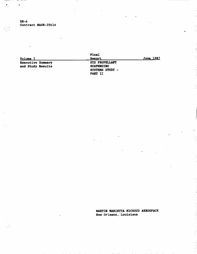
o Option 26 - A self-propelled tank assembly, based on option 2. This concept m l d use much of the hardware and techniques proposed for the
selected STS scavenging method (Concept 6) described in earlier phases
of this study. There are sufficient data to select one of the three options over the
other two. Howewer, such a selection depends on the operational mode to be adopted by the SDV, i.e.:
o Bandezwou8 and dock/barth with the SS; or o Rendezvous at a distance from the SS and transfer cargo by O W ; or o Deploy cargo in a significantly lower orbit than SS for O W retrieval. Option 2/2A offers the flexibility to cover all of these potential
operational modes, while Option 1 can operate only in the first two modes. We have identified no major weight, cost, or technology differences
between Optiuns 1 and 2. Although the self-propelled tank set (Option 2A) incurs soma weight penalty when compared to the other concepts, it offers additional capabilitiem. Our studies indicate that Option 2A could be developed as a field kit modification to Option 2, if required. Figure 1.1-1 shows the UCV reference mission for Option U, while Figure 1.1-2 illustrates *
corresponding tankage concept in greater detail. 1.2 Life Cycle Cost Analysis
STS propellant scavengiw (PSI can deliver cryogenic propellant at a lower cost per pound than the SDV.
The STS-based system can provide up to 144 klb/year of cryogenic
propella& at approximately $420/1b. If more propellant is required--as indicated by the OTV traffic model--it can be supplied by the use of the SDV tanker.
If no STS propellant scavenging system (P/S) is developed and only the SDV propellant transport is used, the cost increases to approximately $8SO/lb. The scavenging of SDV propellant residuals offers some cost benefit by
reducing the delivered cost by about $70/lb.
The combination of STS and SDV scavenging offers the lowest LCC for delivered propellant in excess of 144 klb/year. Using both systems to deliver S40 klb of propellant per year results in a delivered cost of $692/lb.
2

.
/ * /-
U.-/ I
w L

ORIGINAL PAGE IS OF POOR Q U A L m ,
4

. The analysis showed that the transportation cost was the major cost driver. Operations costs were 99% of the total LCC while 87% of the operations cost was the SDV users charge. With these costs dominating the LCC, any changes in DDThE and production costs would minimally effect the delivered propellant cost per pound. 1.3 TASK RESULTS
The most significant results of the Part If task results are summarized below. These results supplement the results presented in our previous report (Reference 1 ) .
1) The Space Transportation Architectural Study (STAS) mission models were used with the PF20 Orbital Transfer Vehicle ( O W ) mission model to identify the proportion of SDV capacity necessary to deliver cryogenic propellant to orbit. The parametric results (Figure 1.3-1) indicate that 45% of the total SDV annual capacity is required for propellant
delivery for the baseline SDV launch rate of 8/year. The use of STS PS reduces the demand on the SDV to 35% of its annual capacity.
2) Our studies showed that SDV residuals scavenging --while cost- effective-- is not a major factor in propellant resupply because the SDV has a much larger cam0 capacity than STS, while possessing the
same residual propellants. Therefore, for a tanker m.ission, the SDV has an inherently higher ratio of capacity to residuals. For the mission models used, SDV propelled scavenging and transport delivered only 10% more propellant than propellant transport only.
3) The STAS mission models showed that 70% to 80% of the cargo mass and volume delivered to orbit must be returned to Earth. This factor causes problems for the potential reuse of PS hardware (e.g., tanks, etc.) since there does not appear to be sufficient transport cargo bay
space available to return it from orbit. Although the mission models used have the STS and SDV to deliver payloads to orbit, only the STS is available to return them. An imbalance of capacity exists. However, we have designed our hardware such that it is capable of return in a STS cargo bay if sufficient capacity exists.
4 ) The interface concepts developed for the STS PS system may be used for the SDV system. Our goal is an interface design capable of use with standard orbital cryogenic disconnects applicable to both the OTV and the SS.

0 0 d
0 (D
0 00 0
0
0 0
% C 0 cu
0
0

5) Hydrogen interfaces between the SDV and ground facilities (for the loading of the propellants to be transported) may be directly adapted from the STS/Centaur program. In particular, the Centaur rolling beam may be used, as well as disconnects, etc. The STS/Centaur uses LO2/G02 connections within the Orbiter payload bay. If this were to be adopted
for a sidemount SDV with a separate PIA module, an interface in the forward skin of the P/A module would be requird. A n alternative approach wwld be to develop an oxygen umbilical from the mobile launch platform (Mp) to the P/L module starboard side. This trade requires detailed cost studies which should be deferred to a later study phase.
6 ) The STS Propellant Scavenging Vehicle (PSW is not the optbum configuration for use on the SDV. Our studies indicate that a more efficient use of the available PIL module volume is a three tank arrangement that has a total propellant capacity of 61.4 klb at a 6 : l
mixture ratio. The two LHZ tanks and one LO2 tank may be arranged at one of two favored locations: the aft end or forward end of the P/L module. Each location offers benefits, but the major discriminator between them was the operational mode of the SDV, at present undefined. Until this mode is defined, a final tank configuration selection cannot be made. However, the forward-mounted tank set, which lends itself to deployment. into a self-propelled vehicle, has the potential for greater operational flexibility.
7) Few negative impacts were found from the incorporation of cryogenic propellant transport into the SDV. These main impacts involved localized restressing, equipment relocation, and provision for
propellant loadiry. Deployable or self-propelled tank sets ~nimally impact the SDV operations since they may be treated as normal deployable payloads.
7
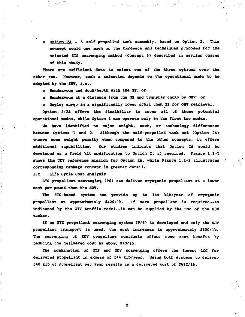
1.4 Conclusions The following conclusions were reached as a result of this extension of
the study. 1) Large quantities of LHZ and LO2 can be delivered to orbit using the SDV
and STS.
2) STS and SDV PS are cost-effective. However, while scavenging is an essential element of economic propellant transportation by the STS, seavarying is not essential for the SDV. The SDV propellant tanker can be a straightfommrd tran8porter.
3) Curtent STS, SDV/UCV, and On lnission models are compatible for propellant resupply. Our baseline models included 12 STS flights/year, 8 SDV flights/year, and 13 On flightslyear. Our studies showed that the SDVIUCV was essential to maintain propellant resupply, while the STS PS operation could provide about 25% of the OTV requirement.
4) On propellant resupply is the largest single SDV/UCV user €or the mission models examined: 45% of the total SDV annual lift capability is required to supply the OTV's annual requiremetnt.
5) The return of the transpott/scavenging tanks to Earth is severely restricted by the absence of return capacity. Since the baseline UCV
does not have a reusable/returnable P/L module, the only return capability is provided by returning STS Orbiters. The mission models
show that there is insuffici'arrt return capacity to allow reuse of a meaningful fraction of the tankage delivered.
6) The only major technology requirement identified continues to be the rematable cryogenic disconnect. This is the pacing development item for propellant resupply.
7) Propellant conditioning should be performed at the SS tank farm (OTV facility). The complexity of any propellant conditioning operation
tends to mitigate against its incorporation into the relatively simple
propellant resupply vehicle. 8 ) A three-tank arrangement is favored for the SDV propellant tanker.
This configuration contrasts with the STS case where a tandem tank arrangement was selected. The SDV P/L module allows a 25 ft width, while the STS P/L bay allows only 15 ft. For volumetric efficiency,
I . i
8

three tanks are well suited to the SDV, while still offering the potential for the return of individual tanks as STS payloads. The single LO2 tank has a 52.7 klb capacity, while the two LH2 tanks each have a 4.35 klb capacity. These volumes provide a total of 61.4 klb-at
a delivered mixture ratio of 6:l.
9) Propellant transport offers minimal negative impacts to the SDV. The
principal negative impacts are the cost and weight of P/L module fixed airborne support equipment (ME). A positive impact to SDV is the potential exists to perform an LO2 jettison in the event of SSWE
failun. This feature can allow ai abort-to-orbit capability for the SDV. This capability is directly analogous to the STSICentaur Transatlantic Abort/Landing Avoidance (TALA) mode.
9

1.5 Recommandations
1) The requirement to transport cryogenic propellant should be an element As a minimlm, UCV concepts should not of the UCV design specification.
preclude the incorporation of PS and/or transport.
2) The SS, OTV, and UCV prosrams should coordinate their activities to allow optimal intwration of the cryogenic propellant resupply, aspecially propellant condition* and interfaces.
I
3) A standard rematable cryogenic disconnect for space operations should be developed. This disconnect is the pacing technology item for on-orbit cryogenic propellant transfer.
4) Both the STS cryogenic PS system and the UCV/SDV cryogenic PS transport system should be developed. For large propellant demand (500 .
klb/yaor), the use of both systems provides the lowest overall costs.
5) The development of a low altitude logistics node should be considered. Significant increases (25% or more) in deliverable propellant mass can
be achieved by basing the OTV facility/tank farm at an altitude of 50
nm or more below the SS.
' .. 1
10

210 STUDY RESULTS - BACKGROUND . 2.0.1 Introduction
Large quantities of cryogenic LO2 and LH2 will be required in the vicinity of the SS to support the space based Om.
A long-term propellant storage facility in the vicinity of the SS can be resupplied With the residual and surplus propellants recovered from the External Tank (FZ) and WPS of the STS. Recovery of these propellants may
offer ‘significant savings over propellant resupply by a dedicated tanker vehicle.
Earlier phases of this study focused exclusively on scavenging cryogenic propellants from the STS. The current study extended the objectives to include cryogenic propellants delivered by the unmanned cargo vehicle (UCV).
Figure 2.0-1 gives the history of the PS study.
PHASE - - VALUE O COUTRMT HAS8-35614 S-t. 19, 1983 - ?larch 19, 1985 $244K o Part I1 Follow-on April 19, 1985 - Feb. 19, 1986 $139K
o Follow-on Change Order 10 Sept. 19, 1986 - Aug; 19, 1987 $ 75K
FIGURE 2.0-1 - STUDY HISTORY
A. Objectives The study built on the results of the previous phases. The principal new
elements were: 1) The use of a STAS mission model; and 2) The incorporation of UCY PS. Also, the period of interest to be studied changed from 1993-2002 to
1995-2010. The principal objectives were:
o o Predict the OTV propellant requirements from 1995 - 2010;
Review the STAS mission model for propellant transport opportunities;
1
(I
11

I
o Review the opportunities for scavenging/transport tank recovery - Feasibility/benefits of tank recovery/reuse; Identify requirements for UCV scavenging/transport tanks; Determine the optimum tank sizing and arrangement for UCV use
- Compare with STS;
o
o
o Develop hardware concepts for tanks; and o Update Part XI coat/schedule estimates.
This phase of the- study focused on the development of a tankage concept to allow the UCV to transport cryogenic propellant to orbit for use by a space
- b-ed OTV. 8. Guidelines and Assumptions
The following guidelines, ground rules, and assumptions were used in this study.
o 1995 Mission Model was baselined: - STds payload manifests were to be used "as is";
* - W D misdons were excluded;
- LIissia model sensitivities were to be assessed. o Launch vehicle architecture included 65 klb payload STS, 150 blb
UCV, and a 30 klb Spaceplane or 65 klb STS 11: - Payload capabilities consistent with STAS;
- Sidemount SDV was baselined.
Propellant required;available was to be assessed: - - sTds/OTV mission model; -
o
1995 - 2010 tiPW period;
Cryogenic space based OTV assumed to exist. o Concept 6 PSV was the study baseline.
* This ground rule was later changed to allow the assessment of the impact
of including W D missions, without requiring the use of classified data.
12

2.0.2 STUDY - PARTS I AND I1 All viable STS PS concepts were. identified and evaluated during Part I of
the study conducted during 1983 and 1985. Concept 6, carried in lightweight ACC, was selected as best based upon the most propellant scavenged at the lowest costllb. During Part 11 of the study, conducted during 1985-1986, this concept was refined and optimized. A detailed hardware description was made and the supporting research and technology required was identified.
Figure 2.0-2 illustrates the self-propelled Concept 6 PSV. This isometric view shows the relative location of the primary components. The main tanks
have cassinian damss to minimize vehicle length.
U 2 6 ELECTRICAL REMATABLE UYBIUWL 7
STATION \ H neSl
FIGURE 2.0-2 CONCEPT 6 PROPELLAMT SCAVWGING VEHICLE (PSV)
The primary engines are 900 lb thrust storable bipropellant engines and the reaction control system (RCS) engines are 25 lb thrust engines. Both engines are currently used on the Orbiter RCS. The two storable bipropellant tanks are positive expulsion tanks which are baselined bellows-type tanks.
13

The in te r face and support s t ruc tu re a r e located a t the forward end of the vehicle. Trunnions, f o r mounting the empty tanks i n the Orb i t e r cargo bay f o r re turn t o Earth, a r e located near the assembly center of gravi ty (cg).
This design places the LO2 tank forward t o minimize the s t r u c t u r a l moments
produced during l i f t -o f f and ascent. The LHZ tank is mounted i n l i n e using a
cy l indr ica l skin s t r i n g e r type inter tank ( U T ) s t ruc tu re fastened t o the
flanges at the equator of each of the tuo tanks. Both tanka are 130.3 in diameter. The LO2 tank is 78 in. lo116 and the LHZ
tank is 82.5 in. long. The PSV dry m i g h t is 34.1 klb based on a 2219
aluminum structure. Figure 2.0-3 show the basel ine mission scenario f o r STS PS.
i
C '
a n c u u n m IN NOMINAL ORBlT CONTINUE ORBITER
FIGURE 2.0-3 COMCEPT 6 HISSIOM SCENARIO
1 4

A typical STS scavenging mission scenatio is as follows: 1) Partially load LO2 scavenging tank with a propellant mass equivalent to
the surplus lift capability during ET loading; 2) Launch and solid rocket booster (SRB) separation; 3) Separate Aft Cargo Carrier (ACC) shroud; 4) Transfer residual propellant to scavenging tanks after main engine
cutoff (WECO); (transfer time approximately 10 minutes); 5) Separate the PSV from the E!C/ACC;
6 ) Fly PSV to orbit in vicinity of SS; 7) Orbital Maneuvering Vehicle ( O W ) rendezvous with PSV and performs
proximity operations for final berthing to the SS storage facility;
8) Orbiter separates from ET after PSV separation; 9) ET reenters atmosphere and the Orbiter resumes its primary mission, and 10) Rnpty PSV returned to Earth in the Orbiter bay when opportunity
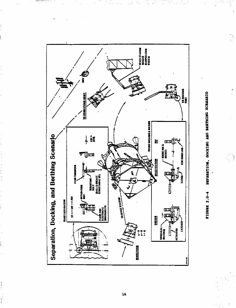
available. Figure 2.0-4 shows the PSV separation, docking, and berthing operations in
greater detail. This scenario illustrates the simplicity of the methods
employed, as well as the utilization of the O W for SS proximity operations. A table of "quick" reference data is given in Figure 2.0-5. Further
details, including an extensive hardware description, are available in Reference 1.
15
m c t 5 Y
m U t (0
c Y u 0
6 - n r" 0 a Q
aa v)
- Y
L
n
+
-- .
0
2 a W u VI
u P
W
3 E a
a 8 - eL W VI
* I
0
h(
W a 3 w L
16
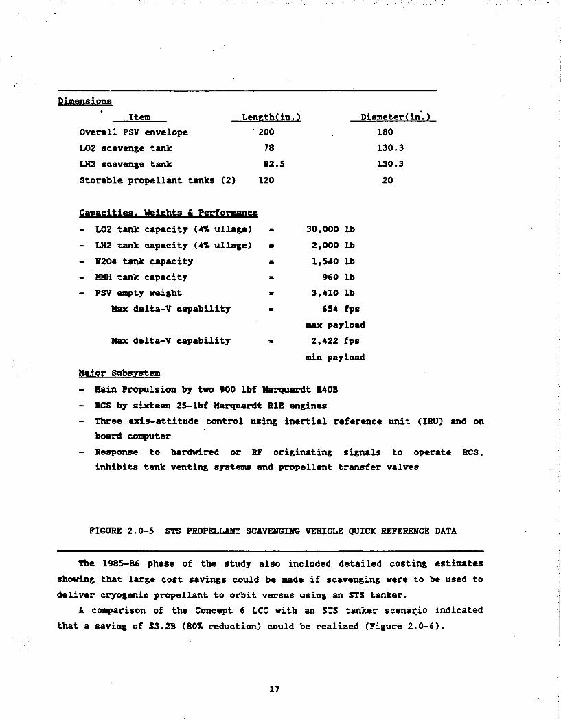
Dimensions Item Length( in. 1 Diameter( in. 1
Overall PSV envelope . 200 LO2 scavenge tank 78
LH2 scavenge tank 82.5
Storable propellant tanks ( 2 ) 120
Cawacities. Ueirhts & Performance
- LO2 tank capacity (4% ullaee) - LH2 tank capacity (4% ullage) - 8204 tank capacity - 'IMH tank capacity - PSV empty weight
Hax delta-V capability
Elox delta-V capability
Major Subsystem
180
130.3
130.3
20
30,000 lb
2,000 lb 1,540 lb 960 lb
3,410 lb 654 fps
IMX payload 2,422 fps
min payload
- Main Propulsion by two 900 lbf Marquardt R40B - RCS by sixteen 25-lbf Marquardt R1E engines
- Three axis-attitude control using inertial reference unit (IRU) and on board computer
- Response to hardwired or RF originating signals to operate RCS, inhibits tank venting systems and propellant transfer valves
FIGURE 2.0-5 STS PROPELUUT SCAVENGING VEHICLE QUICK REFERENCE DATA
The 1985-86 phase of the study also included detailed costing estimates showing that large cost savings could be made if scavenging were to be used to deliver cryogenic propellant to orbit versus using an STS tanker.
A comparison of the Concept 6 LCC with an STS tanker scenario indicated that a saving of S3.2B (80% reduction) could be realized (Figure 2.0-6).
17

$48
Program LCC ($8)
0 1.96 Mlb Propellant Delivered
0 OMV Operations Cost Not Included
STS Propellant Tanker Scavenging Flights - ._
FIGURE 2.0-6 P R O P E ~ SCAVEMGING vs STS TANKER LCC
This saving resulted from taking advantage of the excess payload lift
The elimination of capability predicted for the STS in the years 1993 - 2002. 39 dedicated STS tanker missions (to deliver 1.96 mlb propellant) more than compensated for the additional development, production. and operations costs. Further cost benefits would be realized if scavenging operations included DOD flights.
a launch cost of $lOl.4M. The STS tanker costs were based on the delivery of 50 klb propellant with
The results of the previous parts of this study are summarized as follows: o STS cryogenic PS is technically feasible and cost effective; o More than 2 mlb can be recovered and delivered to the SS in a 10 year
period; PS is relatively insensitive to anticipated STS performance decrements: o
o The free-flying PSV recovers the most propellant at the lowest cost with a minimal operations impact;
18

o Bo new technology is required except in fluid interfaces - Blew fluid interface technology is applicable to all space vehicle
operations; o
o o STS tankers can be eliminated by proper manifesting of payloads and
O W is essential for SS proximity operations; Payloads should be manifested with scavenging in mind;
prwellants; and o Combining Rockwell and Martin concepts delivers largest quantity of
propellant at the lowest $/lb. Inclusion of Unmanned Cargo Vehicle
. 2.0.3
The final phase of the STS PIS Study began in September 1986. The primary objective was to extend the concept of STS cryogenic PS to the UCV. We were directed to use the sidemaunt SDV as the baseline configuration for the UCV.
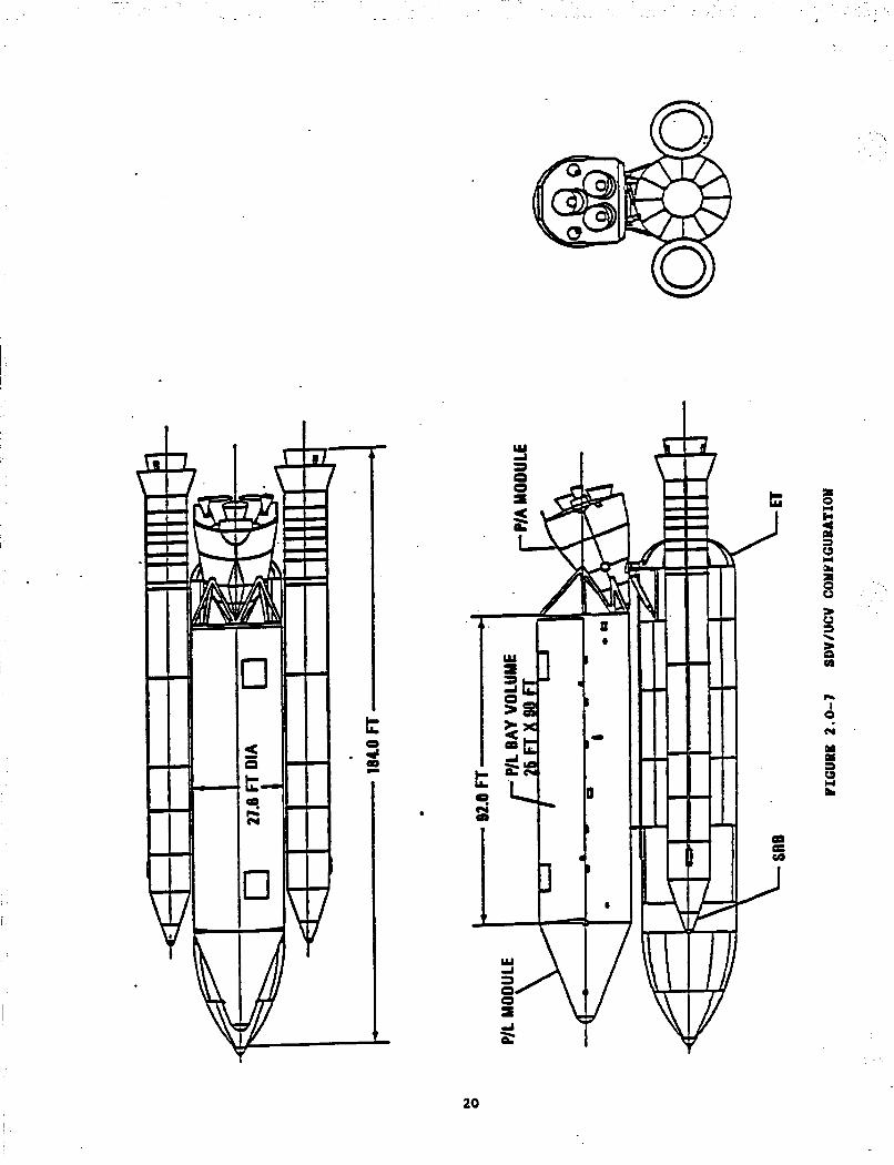
Figure 2.0-7 gives the configuration for the sidemount SDV. This Shuttle Derived UCV configuration represents the class of UCVs
These data are extracted from capable of delivering U O klb payload to orbit. a 1984 Martin Barietta Hichoud Aerospace study (Reference 6).
Uoteworthy features are: the side-mounted P/L module, with internal dimensions of 25 ft diameter and 90 ft length; the conical nose fairing; and the separate PIA module, a recoverable unit containing three SSMEs, an orbital maneuvering systm, and associated avionics.
The P/L module (Figure 2.0-8) provides the structural strongback: o To support multiple payloads; o To take thrust loads from the P/A module; and 0 To provide aerodynamic shielding during the boost phase of the SDV
mission.
The baseline UCV reference mission (Figure 2.0-9) is similar to a standard STS mission with the following differences:
o A payload shroud is jettisoned during ascent; and o On reentry, the recoverable P/A module separates from the P/L module
(which breaks up and is not recovered).
19
t 3 0 4
I '
L a 8
n I 0 h(
Y
c3 L
a a c(
20

-NOSE CONE
1 PIL TO PIA STRUCTURE
BULKHEAD
FIGURE 2.0-8 SDV PAYLOAD MODULE
R
.
FIGURE 2.0-9 UCV B E E " C E MISSION
21

The baseline UCV mission may be impacted by the requirement to transport propellants. The scenario (Figure 2.0-10) offers little impact: it treats the propellant tanks as a payload to be removed and transported by an O W .
This and other scenarios have been examined during tne study.
\
0 ' I
rclQc
--- E=- *
a P
mswnn -1 -- I
FIGURE 2.0-10 UCV REFEREMCE HISSIOU WITH PROPBLUNT SCAVENGING
The mnmiary study plan is presented in Figure 2.0-11. All scheduled work
has been completed and all required documentation has been submitted with the completion of the approved final report. Figure 2.0-12 is the study milestone schedule and documentation plan.
22

m. 3 " c
t- 8 c
a w u) ! 0
..
. - I 0
A I I I
23

.
4 4 4 4 . .
4 4 4 4 4
4
4
I
4
E 4
4 4
1
n a 0 Q
a C
- b
0 - I: .
0 X UI 10 t
a
s x ua
LL Y ua 6 t
24

. . . . . , . . . ~.
2.1 TASK A - Mission Model Update 2.1.1 Preliminary Ground 6hrles and the STAS Mission Model
Preliminary ground mles and assumptions to be used in the UCVISDV phase of this study were as follows. The study would utilize mission models, architectures, payload manifests, and launch vehicle definitions developed for the STAS. Additional payload manifests were not to be developed for this study.
1)
2)
STAS mission model XI shall be used as the basis for this study.
Payload manifests developed for STAS shall be used as is. Only I
civilian payloads shall be included to avoid security classification I
requirements. A reduced size model shall be defined that is approximately SOX of STAS model 11. This reduced size model shall be assessed for impact on PSItransport and LCC. The launch vehicle architecture shall consist of Shuttle I, 150 klb payload SDV amd a 30 klb payload spaceplane. Shuttle I nominal payload shall be 65 lclb; as assumed for the STAS. SDV shall be the sidemount
configuration.
Propellant required and available shall be assessed over the period from 1990 to 2010. The STAS and Om models shall be used to predict propellant requirements.
1
I
I
The Concept 6 PSV shall be the baseline scavenging tank configuration I I I
' . for both STS and SDV use.
The STAS models continued to evolve. Consequently, we examined a series I
of mission models and their effects on propellant delivery and requiremerlts. The first STAS mission models were derived from the results presented in
two STAS reports dated Hay 1986 and June 1986 (References 2 and 3 ) . Using
these references, the payload manifests for the STAS mission model If were
f 'i
I studied and several issues identified:
STAS mission models were volatile. It was difficult to identify an internally self-consistent model which covered STS, SDV, and OTV
operations. Since the STAS was incomplete during our study, any model which we used was subject to revision. Parameters
(a) SDV flights in the period 1999 - 2010 averaged 5 to 7 launches per year, including O W tanker flights;
(b) The space based OTV became operational in 1999;
25

(c) STS was replaced by spaceplane in 2001, thus indicating an incompatibility in timescale between STS scavenging and OTV usage.
(d) Spaceplane flew approximately 25 missionslyear with 30 klb payload.
This scenario resulted in annual civil cargo deliveries to LEO in 2010
being essentially the same as in 1995. This no growth scenario contrasted stroryly with the rapid growth OTV model.
Therefore, by 2010, the OTV propellant was 44% of all SDV cargo (Figure 2.1-1).
hk studied the available propellant from SDV operations 1995 - 2010. Assuming a load factor of 85% (similar to STS in PS-01, Rev. 7 [Reference 41 1, between 100 klb and 150 klb of propellants may be delivered each year of space based OTV operations (Figure 2.1-2).
Figure 2.1-3 shows the OTV propellant requirements drawn from the STAS.
The dashed line shows the trend through the annual data points. When these data are compared.with Figure 2.1-2, it is clear that scavenging from the SQV with the SDV traffic model an 85% load factor is inadequate to cope with O W
demand.
..
In order to broaden our understanding of how the OTV requirement might be met by scavenging from SDV, we estimated the number of SDV flights which would be required to deliver OTV propellant, assuming that the SDVs were each carrying cargo at either an 85% or 70% load factor. This strawman mission model was then compared with the existing SDV (no tanker) model to highlight the differences.
Figure 2.1-4 indicates that SDV cargo load factors well below 70% would be necessary to meet OTV propellant requirements without increasing the SDV flight rate. In some years, the required cargo load factor would drop below SOX. It is questionable whether the OTV and the SDV models are compatible with scavenging as for delivering significant quantities of propellant.
Therefore, we reconsidered the fundamental PS principles which made it a cost-effective prospect for the STS. Parts I and I1 of the study showed that the -.or benefits of STS PS are:
o High annual propellant mass delivered (200 klb), and o Low cost per pound ($420/lb).
26

2 ' g.
.
E
m 0
8
yc 0
rD 0
rc) 0
8
pr) 0
N 0
F
0
8 . 8
m m
x) m
h m
P m
n n
P n n
a a w >
I m Q)
2
5 0
> cn n -
I
N
-
27

0 0 . 0
0 - . . - . .
\ \
> cn+
> cn 23 a
1 1 I I 1 I I I I
8 CD
0
m 3
N 3 a
5 >. r 0
m m
I
N I c
oi

H3V3 81)1 SCL I V Stl3YNVl AQS
- s
- 8
QD -0
I- - 0
(D - 0
ro - 0
- 8
(3 -0
- 8
- 6
8 ,cu
- g
QD - 0 )
r- - Q )
(0 - Q )
rc) - 0 3

In 0 E ln - ln N
b 0
(D 0
L
ln 0
Q 0
0 0
hl 0
a
ar
a
3 s
a cn
In m

These results came about mainly because of two factors in the STS mission models used:
o High annual flight rates (up to 30+ STS flights/year) , which yield many PS opportunities and thus drive up the deliverable mass; and
o The STS residuals were a high proportion of the total propellants scavengeable (residuals plus surplus), tending both to. drive up mass and drive down costs in more indirect ways. The STS residuals were generally 40% to 50% of the total MSS scavenged.
In contrast to the STS case, the SDV had 20% to 25% of the ,flight rate,
while the residuals were inherently a much smaller proportion of the available total lift capability. These factors reduced the deliverable propellant MSS. In addition, the use of a separate PIA module increases the complexity of the scavenging operation compared to STS scavenging.
While our preliminary SDV scavenging results were disappointing, Figure 2.1-4 shows that a major reason for this was the projected demise of the STS
in 2001--the advent of the Spaceplane removed the possibility of scavenging from the STS. However, alternative STAS models existed which substituted an
"STS 11" for the Spacsplane. Such a madel might allow STS scavenging to continue in parallel with SDV scavenging operations.
2.1.2 Updated Mission Model Uew UASA mission models continued to evolve, within and without the STAS.
During our Orientation/First Quarterly Review at LISFC, we were infomed that a new civil mission model would be available as part of continuing STAS
activities. Also, a new OTV mission model became available from MSFC/PF2O during February 1987 (Reference 5 ) .
Our initial ground rules referred to the analysis of civil models only when estimating availablehequired propellants. During the December 1986 review at MSFC, it was indicated that our study should include propellants available for the use of military launches.
The new STAS data were used to derive civil mission models for Architecture B: Shuttles I and 11, 150 klb, and a space based OW. Figures 2.1-5 and 2.1-6 show the required launch rates and the cargo profile for 1995 - 2010.
31

a 0
I I I I I 1 1 I
I I I I
I
U CI
a Y
I
32

b IC (P
m (3
r
b co 0 v) cy (3
co Q, c) Q, cy v)
cy cy t- rn (P *
0 r- cc r- t- t
cy m (P 0 0 v)
Q, (P t- (P t- t
cy v)
0 0 (P
r 0, r- m w 0 W
r cy t- 0 v) v)
I
: I
I
33

Several points a r e noteworthy from t h i s data: 1) Although Shut t le launch r a t e s a r e consis tent with the current ly
projected STS capab i l i t i e s , the exclusion of mi l i t a ry STS launches
makes these r a t e s questionable.
2) Since the UCV launches average two p e r year , there is l i t t l e i f any
growth from 1995 - 2010. 3) Return cargo mass and volume a r e 75% - 80% of the cargo delivered t o
orb i t . Given the existence of the UCV and a l so r e s t r i c t i o n s on STS landing ueishts , s& extra provision f o r returning cargos would be
raquired. The mission modelind, assumes that the UCV is f u l l y reusable and capable of returning cargo t o Earth.
4) The STAS model a s presented does not include the del ivery of the OTV
and its f a c i l i t y t o o r b i t ; it is a s d that t h i s del ivery takes place
p r i o r t o 1995.
Figure 2.1-7 show the c i v i l OTV requirements 1995 - 2010. It is c l e a r
that the model shows l i t t l e j u s t i f i c a t i o n f o r a space based OTV p r i o r t o 2003
and t r a f f i c declines after t h i s date. The t o t a l cargo delivered t o GEO o r b i t averages 20 klb/year from 1995 - 2010. In a l l years but two, only one om mission is flown.
. . I’
I’
34

FIGURE 2.1-7 OTV PROPELLMPT REQUIREMENTS - STAS MODEL OPTION I1
The reason for the exceptionally low OTV usage is evident from STAS mission model ground rules; only "limited" conwercial activity was considered and COMSATS were specifically excluded. nilitary payloads were also excluded.
The new MSFCIPFZO OTV mission model (Revision 10, dated February 6, 1987)
included military Om use. It was noted that only 15% of the total OTV
flights were civil, the remaining 85% being DOD missions. However, the model
did not define military payload masses, consistent with its unclassified status.
35

At this point, we adopted modified ground rules to generate realistic
The following launch system ground rules were adopted:
o
mission models while using the STAS and PF20 data as key reference points.
All STS flights were assumed to carry a lightweight ACC and a PSV. The average delivered propellant quantity per flight was assumed to be 12 klb. !this scavenging capability was based on the results of our Part I and I1 scavenging studies.
o The SDV psplosd factors were based on STS data. Although the nominal
SDV maximum payload continued to be lS0 klb, but a payload weight load factor of 70% and a volume load factor of 80% were assumed. The cargo bay was assumed to be 25 ft diameter and 90 ft long.
o Eight SDV launcheslyear were assumed to take place from ETX. These launch rates wetre based on LC39 limitations, as well as STAS data. Also, post-SlL studies indicate that 12 STS flightslyear is the maximum sustainable flight rate. The eight SDV flightslyear were based on launch pad/VAB limits of approximately 20 launch events/year (12 STS
18 SDW . This factor allowed two civil and six DO0 SDV launches from ETR per year, which is consistent with some STAS models. This approach also allowed the study to use unclassified data while providing an estimate of the propellant available from civil and military launches.
The OTV mission model vas handled in a way similar to the SDV mission model. We addressed the issue of the DO0 portion of the model by assuming that it was a scaled up version of the civil model.
The PF20 mission model, Revision 10, covers the period 1995 - 2010. It consists of the following missions:
o 29 Civil missions “up”; o 11 Civil missions “down”;
o 4 Reflights; and o 176 Generic DOD missions. Ten of the eleven civil down missions were to be combined with up
missions, yielding a total of 210 OTV missions in the 16 year period. This figure corresponds to an average mission rate of a little more than one per month.
36

Total civil cargo masses, 1995 - 2010 were: o 330 klb "up"; and
o 46 klb "down" The DOD payloads were undefined as to payload masses. The only DOD
mission information other than flight rate was some detail of the destination orbits. 55% of the military OTV missions were to go into GEO orbit, the other 45% destined for mid-inclination orbits. lo other details are given.
We made the following assumptions in order to deal with the military portion of the mission mode:
o DOD missions to be identical to civil missions in terms of cargo masses
o Hid-inclination missions depart from the Om facility at 28' inclination, similar to the CEO missions. Since the destination orbit was otherwise undefined, we assumed the required delta-V for the plane
change to be identical to that required for GEO insertion and circularization.
and up/down mission ratio, i.e. simple scaling.
o The four reflight missions were payload delivery only which would minimally effect the overall model.
All OTV missions were assumed to be the same in terms of up/down payloads. Over the period 1995 - 2010, this assumpfion allowed smooth annual. requirements to be derived.
Therefore, average OTV mission flown 210 times consists of the following two elements:
1. Delivery of 11.5 klb payload; and 2. Retrieval of 3.6 klb payload.
This reference mission was them evaluated to calculate the OTV propellant requirements. For study purposes, the Om (with L02/LH2 propulsion) was
assumed to be reusable and space based. The Om performance calculated for this study assumes that the mission
requires three bums plus aerobraking. fps. The return burn is 4.8k fps, followed by 7.5k fps aerobraking maneuver.
The two insertion burns total 12.3k
Figure 2.1-8 illustrates the OTV performance assumed for delivery of
payloads. Payload retrieval performance is shown in Figure 2.1-9.
37

65
60 55
0 50 I 45
40 I - 35 3 Q 30 2 25 n
n Z 15
10
5
0
x
m
C
P
- a 20
3
0 8800 Ib empty O N 0 Aerobraking return
No down payload 0 450s Isp
1 I 0 10 20 30 I I I I 1 I
55
50
5 45
2 35
g 20
I 40 UI m
5 30 2 25
15
-
0 2 10
5 0
Payload. Mass Up-klb
FIGURE 2.1-8 OTV PEXFORMANCE - UP
0 8800 Ib empty O W 0 Aerobraking return 0 No up payload 0 450s Isp
I 0 10 20 30 I I I I I
Payload Mass Down - klb
FIGURE 2.1-9 OTV Performance - Down
38

U s e of this average mission over the 210 OTV missions shows that 8.68 mlb of LO2 and LH2 (at a 6:l mixture ratio) would be required between 1995 - 2010, including the 1.075 propellant handling factor from the STAS.
. Since the OTV mission model is relatively invariant year-to-year, an
estimate of the annual OTV propellant requirement was made by dividing the total of 8.68 mlb by the number of years (16). This procedure yielded an annual propellant requirement of 540 klb, 2.1.3 Compatibility of OTV, SDV, and STS Models
The new "baseline' mission model was used to estimate the capabilities of the SDV and STS to deliver OTV propellant to orbit.
The analysis showed that the projected annual propellant requirement could be met by SDV delivery when the cargo might load factor was 50% or less. If STS scavenging was also employed, the maximm allowable SDV load factor rose to 63%. Figure 2.1-10 illustrates the reduction in propellant delivered using an increasing cargo load factor.
600
550
500 e !$ 450 !?! 3 400
- 350 21 g 300
E 250
200
150
100
50
0" C
0
0 3
U
OW annual requirement PF 20 Rev 10
0 12sTsmissi0ns/year
---- 8SDVmissions/year
30 40 50 60 70 80 90 100
SDV Cargo Load Factor %
FIGURE 2.1-10 PROPEL- DELIVERED PER YEAR
. .-
39

The results of Figure 2.1-10 indicated that the baseline mission model (8
SDV launches/year) might not meet the requirements of the OTV model, particularly during periods of sustained high cargo load factors. Accordingly, we conducted a parametric study of the effects of varying the SDV launch rates and the load factor. It was assumed that 540 klb of OTV propellant was required per year. Figure 2.1-11 shows the results of this parametric study.
SOV Delivery Only
SOV & STS Delivery
STAS: 2 only Study Baseline STAS: 11/2
1 - a8= I 1/07
2 4 6 . 8 10 12 14 16
SDV Annual Launch Rate Required
FIGURE 2.1-11 SDV LAIRSCHES REQUIRED TO DELIVER OTV PROPELLANT
0
20 aP I
0
L
b
40 5 B
60 o
0 >
80 %
0
$
100
~~~ ~
A8 the SDV launch rate increased, the available unused or surplus lift capability increased, for a fixed load factor. This means that the maximum allowable cargo load factor to allow delivery of propellant as surplus also increased.
Figure 2.1-11 covers the range of SDV launch rates existing in several
recent STAS mission models and also shows the effects of STS scavenging to augment SDV deliveries.
Any combination of launch rate and load factor to the right of, and above, the curve will satisfy the Om requirements.
40

SDV Fekiduals rrcavenging appears to offer only marginal benefits. For residuals of around 6 klb/flight, and 8 flights/year, the total contribution of residuals scavenging is less than 10%' of the OTV annual requirement. Therefore, SDV residuals scavenging becomes an option which is based on cost effectiveness issues rather than essentials. The baseline SDV propellant
delivery mission becomes a tanker rather than a scavenger/tanker.
2.1.4 OTV Facility Basing Altitude Significant gains in propellant delivered may be realized by basing the
OTV propellant depot in an orbit lower than that of the SS. For a dedicated SDV tanker mission, gains of only 10% or less can be
made. However, for mission models involving the use of surplus lift capability for propellant resupply, gains of 2% or more can be achieved. This capability may save the equivalent of one or more dedicated SDV missions/year (Figure 2.1-12).
50
C ; 20
d
Effect of SDV Cargo Load Factor
0 Basing Altitudes for OW Facitity are Relative to Space Station
0 10 20 30 40 50 60 70 80 90
SDV Cargo Load Factor - Percent
FIGURE 2.1-12 OTV PROPELLANT DELIVERED BY SDV VS FACILITY BASING ALTITUDE
4 1

The reason for this effect is that SDV lift capability decreases with increasing destination altitude. If propellant flies on a space available basis to create weight-limited missions, lower destination altitudes will give
higher surpluses and, thus, more propellant.
The O W delta-V requirements were only minimally increased by basing the depot at a lower altitude.
I
42

2.2 TASK D - Optimum Tank Sizing and Arrangement Previous phases of the study developed an effective method of STS PS based
on a PSV located in the ACC.
Extension of the study to include the UCV led to tankage requirements which dictated the review of alternate arrangements and capacities. Factors governing the final selection of UCV propellant supply tankage are:
1. Desirability of carmPanality with the PSV proposed for the STS;
2. Reusability of tankage (interaction with Task B); 3. Hode of operation of UCV, i.e. does it visit the SS or close vicinity,
or does it deploy payloads into a lower orbit for retrieval by the O W ? Is the UCV cargo bay itself a reusable/flyback item?
4. Available surplus lift capability/volame flight-to-flight between 1995-2010 (interaction with Task A>;
5. Desirability of scavenging residuals from the E T / M P S , i.e., with low annual flight rates and large surpluses, residuals become a smaller proportion of the propellant available than for the STS;
6. For the purposes of this study, we examined 15' and 25' diameter bays. Several other sizes were considered in the STAS ranging from 15' x 60' to 25' x 90'. Other studies have considered larger sizes.
Consideration of the above requirements led to a range of possible options for UCV tankage. Figure 2.2-1 lays out some of the interactions between these requirements. 2.2.1 optimum Tank Sizing
The Task A results indicated that fewer scavenging opportunities will be available from the SDV than the STS. However, the total mass available per
-
flight would be greater due to the larger lift capability of the SDV.
Task A showed an OTV annual propellant requirement of about 500 klb, coupled Kith an SDV launch rate of about 8/year, and an STS launch rate of 12/year.
The Task A results led to the following tank sizes: o If STS PS is developed, the SDV will be required to deliver about 45
klb OTV propellant per SDV mission. o If no STS PS is projected, each SDV mission must deliver approximately
62 klb propellant.
43

44

For design purposes, it was assumed that there will be no STS PS. However, if the SDV can accommodate the larger tanks required by this scenario, it can also accommodate the smaller tanks utilized should STS
scavenging be developed. Alternatively, the larger tanks would fly fewer SDV missions. For study *purposes, we selected the 137-in. diameter tanks as our baseline. Two LH2 tanks and one LO2 tank will fit into the 25 ft diameter payload bay, allowing clearance for installation/removal as a unit. In addition, individual tanks can be returned to Earth inside the l5 ft diameter cargo bay.
Allowing for a 5% ullage volume, the LO2 tank can contain 52.7 klb LO2, and the two LH2 tanks a total of 6 . 5 klb LH2. This capacity yields a
delivered mixture ratio of ‘8: 1. Incorporating short barrel sections into the two LH2 tanks allows use of a
similar dame geometry for all tanks, reducing the mixture ratio to the required 6 : l . This change provides significant savings in tooling and manufacturing costs while allowing efficient use of the available P/L bay space.
Each LH2 barrel section is 30 in long yielding a total LH2 capacity of 8700 lb.
Figure 2.2-2 sumPnarizes the leading characteristics of the tanks.
J I LENGTH(II) IULLAGE VOLUWEICAPACITY(LB)L I I I I
DIAHETEB( IN)
I
I I 52700 I
I 5%
5%
I
I 13 7
16 7
I
I 1 3 7
1 3 7
I
I LO2 TANK
LH2 TANK
I
I I 2 x 4350
FIGURE 2.2-2 TANK DIMEUSIONS AM) CAPACITIES
The combined capacity of the LO2 and 1312 tanks is 6 1 . 4 klb. This capacity corresponds to 41% of the SDV lift capability. Allowing 6 klb for tanks, the lines and support structure will require 45% of the SDV lift capability for propellant resupply.
.i
45

2.2.2 Tank Arrangement Options The results of Task A, the mission model updat;, showed that many SDV
cargo flights were manifested with multiple (10 to 15) payloads. This model
produced great uncertainty as to the size and shape of the remaining cargo voltrma(s). In addition, STAS manifesting did not consider SDV cg limitations or payload packaging for each miaaion as was done for previous scavenging studies. Therefore, our tank arrangenmlt studies could not consider SDV cg limitations or payload packagiry.
Our evaluation of candidate tank arrangements was driven by two main considerations.
1) The tanks used should minimally impact the SDV cargo capacity, i.e.,
the payload bay volume occupied by the tanks should be at a minimum. 2) Requirements for scavenge tank return dictate that tanks fit into the
STS cargo bay. This factor restricts individual tanks to less than 15' diameter. although a multi-tank arrangement may exceed this parameter when assembled.
Ue d n e d four tank arrangement/installation options. 1) Concept 6, P W (identical to the STS based system); 2) Fixed or built-in tankage (located in the SDV payload module); I
3) Deployable tankage (located in the SDV P/L module against the aft
They were:
bulkhead) ; and
4) Deployable tankage (located in the nose cone of the SDV P/t module). Application of the Concept 6 PSV to the sidemount SDV configuration is
straightforward. Consequently, it employs a LUACC and operates identically to the STS PS system. Figure 2.2-3(a) shows its use* assuming the cargo bay to be volume limiting.
Figure 2.2-3(b) shows the Concept 6 PSV in the weight limited SDV. In this case, the PSV is mounted in the cargo bay, but facing aft when compared
with the ACC installation. This placement simplifies propellant interfaces and may allow the PSV to be cantilevered from the cargo bay aft bulkhead.
46

... .
.
(a) PSV i n LWACC
(b) PSV i n PIL Module
PICUBE 2.2-3 COUCEPT 6 PSV ALTERNATIVE IUSTALAATIOUS
The Concept 6 PSV is inappropriate t o apply t o SDV, par t i cu la r ly i n view of the STAS mission model. The PSV is sized a t 30 k lb LO2 capacity and 2 klb
LH2 capacity. These sizes derived from t h e of STS manifesting process and the
incorporation of residuals scavenging. The SDV's increased l i f t capabi l i ty and reduced launch rate favor la rger tank capaci t ies where the tanks are
47

filled on all occasions, rather than the available surplus approach used on the STS. The PSV tanks may be increased in length by the insertion of barrel sections. This approach could evolve into. an SDV pure tanker which would be capable of return inside the STS P/L bay. However, the PSV inefficiently uses
the available P/L module diameter since the PSV is sized at an overall diameter of lS* for return in the STS P/L bay. Using the optimum tank capacity (derived in Section 2.2.1) results in a tank set length of 44 ' if the PSV tank diameter and arraryememt are to be retained. However, the use of a self-propelled tank unit may be viable if it is optimized around the SDV P/L
module dimem8ions. To permit the opthum use of remaining cargo volume consideration was
siven to installing separate LO2 and LHZ tanks in the SDV .
PI- 2.2-4 SDV UITH BUILT-IN TAMLAGE
_ _ _ _ ~ ~ ______
Figure 2.2-4 illustrates a concept for fixed or built-in tankage. The
tanks shown take advantage of a 25' diameter bay and provide a simple, lightweight installation with the mininnnn length. In addition, the individual built-in tanks were sized to €it in a lS* diameter bay which may be useful if more than one UCV bay diameter is developed.
Fixed or built-in tankage has the initial attraction of being operationally simpler, avoiding the installation and checkout of tank/P/L module interfaces at the launch site. However, it is potentially costly if the P/L module is not reusable and the OTV and SDV mission models fluctuate. Built-in tanks may be a feature of a particular SDV that may be disposed of without having been used.
I

1 - A
Therefore, we studied two further alternative configurations which would p e d t tank deployment and give maximum operational flexibility. The two configurations have most components in comaon, but represent different
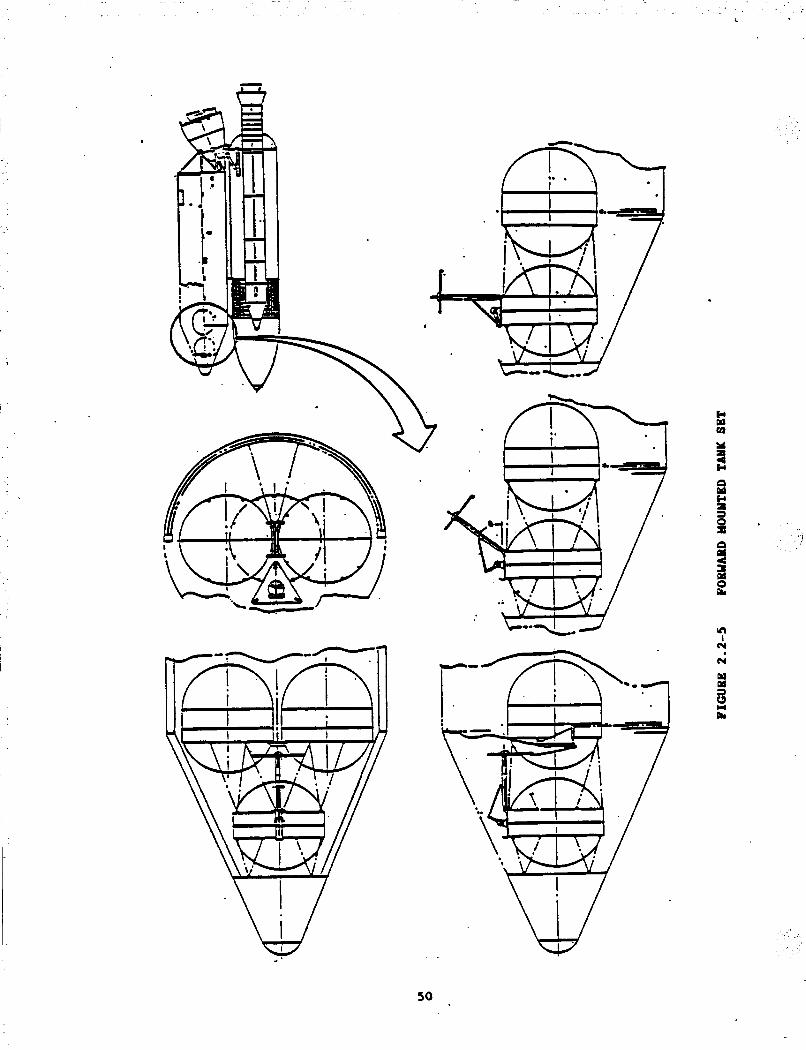
installations within the SDV P/L module. Ovtion 1 involves placing the three tanks in the nose section of the P/L
module (Figure 2.2-5). Option 2 also requires three tanks, but they are located at the aft end of the P/L module, supported against the aft bulkhead: (Figure 2.2-6). The geometry of Option 2 requires a minor reduction in tank diameters; short barrel sections are inserted to *compensate for this reduction.
In both cases, tank sets are deployable and reusable as units. If no
vehicle is available to return them as a unit, the individual tanks will fit within a 15' diameter cargo bay. Tank sets would be installed as P/Ls at KSC and loaded with propellants on the pad exactly as Shuttle/Centaur or SDV/Centaur.
lo strong discriminators were found between the forward and aft mounted
1) The forward-mounted tank unit offers a better use of the available P/L
module volume. The nose cone location minimizes the intrusion into cargo volume. This factor may become important if the SDV PIL module
is reduced in length from the present 90' nominal.
tank sets. Points considered were:
2) The aft mounted unit requires a less complex propulsion installation. Essentially, the sawing consists. of the deletion of an additional 90'
of plumbing for loading and venting. 3) The P/L module cg tends to follow the location of the propellant tanks
which has implications for the required SSXE gimbal angles. Also, a
forward cg would yield a minor overall performonce improvement for a sidemount SDV, due to the reduced offset of the vehicle thrustline from
the flight path vector. 2.2.3 Tank Configuration Selection
Factors governing the final selection of the tankage configuration were outlined in the introduction to this Section 2.2. Our studies narrowed the major uncertainty to one: the operational mode of the SDV. In summary, the SDV can operate in one of three ways: (1) It can visit and berth with the SS;
1
49
. . . . . . . 1
\\
W
E v)
VI 1
cy
cy
so

~
1
. ..
I I
I W
51

(2) it can rendezvous i n the v ic in i ty of the SS using the O W t o deploy its cargo; or (3) it can i n j e c t i t s e l f in to an o r b i t below the SS using the OHV t o
give the large delta-V required t o each of its cargo elements. For each of
these operational modes, there is a preferred tank mode of operation:
o
o
o
Built-in tankage f o r SS v i s i t s by a berthing SDV;
Deployable PSV f o r use on a v i c i n i t y SDV; and
Self-propelled PSV f o r use where the SDV does not v i s i t the v i c i n i t y of
the ss. In view of the uncertainty of the SDV's mode of operation which is outs ide
the scope of t h i s study we selected the deployable tankage concept f o r f u r t h e r de ta i l ing f o r the following reasons:
o It is readi ly adaptable t o become bui l t - in a t a la ter stage--the
corol lary being not necessarily t rue; and
o The forward-mounted tank set possesses b iax ia l symmetry which lends
i t s e l f t o development in to a self-propelled vehicle or PSV.
2.2.4 Self-Propelled Tanlc Unit
Previous phases of t h i s study showed t h a t a self-propelled tank set was
advantageous f o r STS PS. Our experience i n developing t h i s concept, coupled with the SDV operational issues (mentioned i n Paragraph 2.2.3) led us t o consider the potent ia l benefi ts of applying the self-propelled tank concept t o the SDV.
Major fac tors favoring such a vehicle are: 1) w e r a t i o n a l F l e x i b i l i t y
The SDV does not have t o v i s i t the OTV f a c i l i t y i n order t o de l iver
propellant t o it. There a r e reasons ( la rge ly outside the scope of t h i s
study) why the OW f a c i l i t y might not be co-located with the SS. The
use of the self-propelled tanker vehicle allows the SDV t o v i s i t the SS
while the tanker v i s i t s the OTV f a c i l i t y . The tanker can perform
o r b i t a l phasing and a l t i t u d e changes independently of the SDV.
2) The OMV Workload Can B e Reduced
I n the case of an SDV mission which does not v i s i t the O W f a c i l i t y , a
high t o t a l impulse mission may be required t o del iver the tank set from
the SDV t o the f a c i l i t y . The use of an in tegra l propulsion system
allows the high impulse t ransfer t o be made without committing t h e
52

. -
valuable resource of the O W . For such a mission, the O W would only be used for the proximity operations, i.e., bringing the tank set into a berthing condition at the OTV facility. This scenario is similar to that developed in Reference 1 for the STS scavenging system. Figure 2.2-7 illustrates the STS/PSV transfer and berthing scenario.
o Tank Disvosal Methods Are Simplified If sufficient transport capacity is available to return tank units to Earth (Section 2.11, the tanks must be deorbited in a controlled manner. The self-propelled tank set offers a self-deorbit feature, simplifying disposal operations, and eliminating the risk of losing the O W on a deboost/reboost trajectory. The overall propellint
expenditure would also be minimized. Figure 2.2-8 shows the mission scenario for an SDV/UCV equipped with a
self-propelled tank set. The use of the tank set can have minimum impact on UCV operations. The tank set can be deployed like a self-propelled P/L and can transport its propellant to the SS/OTV facility independently.
53

.# /
rn S s - Y L 0)
U S Q
m
cr, S
0 0 r: n
f
n I
N
N
Y LI
c( L 3
54

,
/
a
55

2.3 TASK C - Interfaces The operations required of the PSV impose a large number of functions on
the interfaces. S t m c t u r a l in te r faces must be made w i t h the SDV P/L bay and
the SS, as w e l l . as the O W ( f o r some concepts). In addi t ion, f l u i d and
e l e c t r i c a l interfaces a r e required with the SDV P/L bay, the SS and the EILP or
tower.
Overall functions which must be performed by the in te r faces are: 0 Struc tura l support; o Docking/berthing;
o Venting; o Status/checkout; and
o Separation; o Electrical power
o Fluid t ransfer ; Most of these functions a re common t o any space vehicle in te r face .
However, f o r cont inui ty with OTV and SS, we proposed that standardized,
universal in te r faces be developed. Such standardized umbilical assemblies
would include l iquid, gas, and e l e c t r i c a l disconnects. These disconnects
would be automatic., remotely controlled, minimize leakage. and be compatible
with the space environment. During an earlier phase of the PS study
(Reference 11, we developed a concept f o r such a disconnect (Figure 2.3-1).
FIGURE 2.3-1 PSVIACC ATTACHHEBIT AND UHBILICALS
ORIGINAL PAGE 1s .OF POOR QUALlTY
56

. , .
The SDV's deployable tanks will use the same standard I/F proposed for the PSV during the earlier phases of .this study. These I/Fs consist of a LO2 and LH2 disconnect, each incorporating fluid and electrical disconnects as well as structural ZIPS.
The PSV structure attaches to the ACC by four bolts that fit through ball and socket joints secured by pyrotechnic separation units. The separation nuts use USBI 1OSPC-062 SBB parachute release nut components' repacked into a ball fitting assembly.
The PSV attaches to the SS by two latcheb that engage standard 1 klb class bomb lugs (MS3314). Attachment occurs after the PSV ball fittings mate with the sockets at the SS OTV facility.
The umbilicals are match tool-machined structures that precisely locate the fluid disconnect valves and electrical connectors relating to the ball or socket. Therefore, when the PSV is mated--to either the ACC or SS--the
opposing valves and connectors are brought into alignment for mating, separation, and reranting. 2.3.1 Ground Interfaces
By contract direction the sidemount SDV was selected as the baseline UCV for this study. In the area of ground interfaces, this has the advantage of a LH21GH2 umbilical (already developed for the STS/Centaur program) which can be used for the scavenging system. However, an inline SDV configuration would . I
not enjoy the same advantage. I
Figure 2.3-2 shows the geometry of the Centaur rolling beam, as modified
from the STS configuration to the UCV (sidearount SDV) Figures 2.3-2 and 2.3-3 are taken from a Martin Marietta Kkhoud Aerospace study, August 1984, under I AFSD Contract FO4701-82-C-01152, SBL-03 (Reference 6).
Compared to the Orbiter, the larger size UCV causes the following modifications to the Orbiter-Centaur roiling beam: a 175-in. increase in height, a 7 increase in operating angle; and a 44-in. outboard change in the retract start position. These modifications would require a retest of the rolling beam umbilical system.
I
0
i The STS/Centaur uses L02/G02 connections inside the Orbiter P/L bay.
Should these connections be adopted for the sidemount SDV with a separate PIA module, an interface would be required in the forward skin of the PIA module.
i
57

n 0 w t.
4 w
58
2 c 4 4 w w
-. . ... , . _. - . . .
h( I
m el

,
Y a
w d w
c.c Y Y
m I m
N
59

Figure 2.3-3 further details the ULV/Centaur interface kit. Of particular
interest for this study are the P/A-to-P/L module LO2 connection and the LH2 disconnect on the port side of the P/L module. This concept is directly
applicable to a cryogenic tanker using the sidemount SDV.
oxygen umbilical directly from the MLP to the P/L module starboard mid-body. An alternate approach to the P/L-to-P/A module LO2 interface would be an
The use of a dedicated umbilical from the M p directly to the P/L module
provides operational simplicity and potential cost savings. These propellant loading procedures would be simpler than the STS/ACC or ULV/Centaur concepts since they would. be largely independent of ET loading operations. The T-0 umbilical separation is also potentially simpler than the in-flight closure of a disconnect in an aerodynamic surface of the PIA module.
The major difficulty is defining an acceptable retraction sequence and location to avoid damage on launching. Major Mp and/or TSM changes would be required. Our 1982 SDV Technology Study (Reference 7) addressed a similar case and suggested that a separate short tower should be built to accommodate such a LO2 umbilical.
Ue conclude that the option to develop a dedicated LO2 loading umbilical should be examined in conjunction with detailed cost studies. Accordingly, this trade should be deferred until a later phase of the program. 2.3.2 Flight Interfaces .
a n y of the issues generally relating to interface operation on orbit were dealt with in the introduction to Section 2.3. The operational scenario for SDV PS interfaces is similar to that for STS PS (Section 2.0, and Reference 1) .
However, the LO2 disconnect incorporates a feature not used on the STS based system, i.e., a provision to perform an emergency LO2 dump in flight. In the event that the SDV should suffer an engine failure during the latter part of its powered flight, a dump of the 53 klb of LO2 in the tankage aasembly may allow the SDV an abort-to-orbit instead of a lost mission. This
concept is an extension of the Shuttle/Centaur TALA mode. The design concept for the LO2 dump system is shown in Figure 2.3-4. The discharge line may have to be extended along the P/L module to avoid LO2 impingement on the ET or P/A module. This is an element requiring further study.
60

FIGURE 2.3-4 FORWARD TAM( CLUSTER LO2 FLIGHT EHERGENCY D m
A second major difference between STS and SDV in flight interface requirements is that, unlike the STS based system, no residuals scavenging is baselined for the SDV based system (Section 2.1.3). Thus, no fluid interface is required between the P/A and the P/L modules for in-flight transfer of
propellants. However. the LO2 ground loading may require such an interface (Section 2.3.1). 2.3.3 Propellant Conditions
Interface units on the scavenging/transport tanks and at the SS should be capable of handling propellants at a range of saturation conditions. Propellants will be loaded into the tanks at a saturation pressure of about 15 psia. Transit times to the SS and heat leaks will ensure that saturation pressures will rise above this pressure.
,' I
61

I -
-
Typical t ransi t times t o the SS will be one t o three days. Incoming heat
f lux w i l l r e s u l t iq approximately 1 psi/day rise i n LO2 tank pressure and
2 psi/day i n the LH2 tank pressure. I f res idual scavenging is t o be
incorporated, a fu r the r rise i n sa tura t ion pressure (up t o 4 p s i ) may r e s u l t .
Therefore, in the general case, t he propel lants delivered t o the SS w i l l be
saturated between 16 and 25 psia .
RtAs saturation rate may impact the design of the o r b i t a l cryogenic
s to ra se f a c i l i t y . To avoid boiloff losses , the s tored propel lants are maintained below 25 ps ia , the stoaase f a c i l i t y should be designed t o c h i l l the
delivered propellants before miXing them with the bulk storage. This approach
indicates a possible requirement f o r the o r b i t a l s torage f a c i l i t y t o
incorporate a "front-end" propel lant conditioning u n i t f o r incoming propel lant .
, *_ . .. -
62

2.4 TASK F - Hardware Description The three tank configurations developed under Task D were described in
Section 2.2. For convenience they will be referred to as follows: Ovtion 1 - The tank set munted in the aft end of the P/L module. Ovtion 2 - The tank set mounted in the forward end of the P/L module,
intruding into the nose cone.
Ootion 2A - Option 2 with the addition of a storable propellant pr-lsion system, i.e., a self-propelled tank unit.
Weight sumrmaries for these options are presented in Figure 2.4-1. The three configurations have many comon fdtures although there are
minor structural differences and, in one case, a storable propulsion system which accounts for the weight differences.
These weights do not include lLSE or modifications to the UCV/SDV. These issues are quantified elsewhere in this report (Section 2.6).
The majority of the tank set structures are assumed to be aluminum lithium
alloys. The use of these alloys was discussed extensively in the previous
phase of the study (Reference 1). For the self-propelled vehicle, a storable propellant load of 2.5 klb
w w l d be sufficient to transfer the vehicle from a 160 nm to a 250 nm circular orbit.
TANK SET WEIGHTS ( lb)*
Subsystem Structure LO2 Tank LH2 Tanks TPS O2/H2 Tank Propellant Management 02/W Plumbing Systems Avionics/Electrical Storable Propulsion System
TOTAL DRY WEIGHT
Ovtion 1 6 73 337 535 199 440 498 94 -
2776
Ovtion 2 600 34 7 566 199 440 498 94
2744 - -
* Includes 10% Contingency ** Plus Storable Propellants up to 5000 lb (Mission Dependent)
FI- 2.4-1 WEIGHT SUlMARIES - TAM( SETS
Ovtion 2a 597 34 7 566 202 440 498 189 6 91 3530** -
Appendix I gives detailed weight sununaries €or the three options.
63

2.4.1 SDV Payload nodule PigGre 2.4-2 shows the la rges t s t r u c t u r a l modification made t o the SDV P/L
module. The change consis ts of removing p a r t of t h e nose cone and attaching
it t o the je t t i sonable shroud. This change has two beneficial resu l t s :
o Access t o a forward mounted tank set is improved, s ince t h i s tank
option takes advantage of the previously empty nose cone volume; and
o By t ransferr ing p a r t of the nose cone t o the je t t i sonable shroud, a
gain in SDV l i f t capabi l i ty is made. Since the shroud is je t t i soned only 240 seconds i n t o f l i g h t , a s ign i f icant 'por t ion of the nose cone
s t ruc ture does not have t o be transported t o orb i t .
Equ ipmen t changes t o P/L module systems, caused by the nose cone
modifications, a r e limited t o the relocation of RCS components. Figure 2.4-3
shows the Option 2/26 tank set (PSV) mounting frame a t S ta . 558 of the P/L
module RCS components.
In addition t o the PSV mounting frame, the Option 2 or 2A tank set a l s o
has a support frame a t P/L module Sta. 808 (Figure 2.4-4).
2.4.2 Tank Sets
The self-propelled tank set, Option 26, is shown i n Figure 2.4-5. This
view focuses on the simple s t ruc tura l concept of the tank set. The propulsion system is a lso shown.
FIGURE 2.4-5 OPTION 2A - TRIHETBIC VIEW
. . z..
- ,' . ._ .
64

PAGE IS QUALITY

Y 0
v) W z (3 G rn 8
> 2 a 2
66

, . -
I
I I z
U ’
a 2
m - h
c? 0
e L
67

Noteworthy features are: o Standard berthing interface - identical to that of the STS/Concept 6
PSV; corrmaonality with the OTV is high recommended; o The composite leaf-spring on the forward interface; o Accessibility and compactness of the central propulsion/avionics unit; o 12 STS secondary RCS thrusters (25 lbf bipropellant units) for attitude
control; . o 2 STS primary RCS thrusters (900 lbf bipropellant units) for primary
propulsion; and o One pair of positive-expulsion storable propellant tanks with a
provision for a second pair to meet future mission requirements. The storable propellant propulsion system installed on this tank set is
adapted from the Concept 6 PSV. Each oxidizer tank holds 1.54 klb of 1204, while each fuel tank (of identical volume) contains 960 lb of MWI.
One pair of storable tanks gives the tank set a maximum delta-V capability of 3l5 fps with P full P/L. of 61.4 klb cryogens. Ten% of the theoretically available delta-V has been allowed for RCS expenditure.
Thus, one U204/w" tank pair will allow the self-propelled tank set to tradsfer itself from an initial 160 nm circular orbit to a 250 run circular orbit. A second tank pair will double this capability.
I
Figure 2.4-6 shows a three-view drawing of the Option 2A vehicle installed in the SDV P/L module. Since this vehicle wili be deployed from the P/L module to journey to the SS, we have considered the elements necessary to perform a successful deployment.
68

FIGURE 2.4-6 SELF-PROPELLED TANK SET (PSV)
Figures 2.4-7(a) and (b) illustrate part of the deployment sequence. The deployment scenario starts (at t h TI with the firing of four
explosive nuts at the forward PSV/P/L module interface. The PSV clock sequencer then starts. The release of the interfaces allows a preloaded, composite, leaf spring to move the PSV four inches aft. The pivoting bipod assembly guides the PSV.
69

The bipod separates a t TM.5 seconds taking with it the emergency LO2 dump umbilical (Figure 2.4-7(a). S h l t a n e o u s l y , a br ie f f i r i n g of the P/L module RCS produces a -2 acceleration. This act ion starts the PSV ro ta t ing about the pivot.
After 45' PSV p i t ch rotat ion, the P/L module RCS stops f i r i n g and the PSV pivots off t he release l ink, with adequate l i nea r and angular ve loc i t ies
t o complete the separation (Figure 2.4-7(b). As the PSV p i t ch angle r e l a t i v e
t o the P/L module approaches 90 , the clock f i r e s the two forward RCS
th rus te rs on the PSV t o cancel the p i t ch rate; t h i s a l so adds separation
velocity. After a 200 f t separation is achieved, the independent PSV mission
starts and the vehicle injects i t s e l f in to its t ransfer o r b i t t o the SS.
0
I
...
70

A backup scenario exists, should the RCS fail in the P/L module. If the PSV fails to detect any pitch rate, it fires four RCS thrusters to produce a pitch couple about the release link. The remainder of the scenario is similar to the primary made.
The opportunities for the use of conanon components for STS and SDV tank sets or PSVs are:
o Interfaces - Mechanical, electrical and fluids interfaces can be
identical. The benefits of simpler and cheaper development apply also to the SS OTV facility where the use of' a universal interface for PS/transport and for OTV would bring significant benefits (Section 2.3).
o Avionics - The avionics systems of the Concept 6 PSV and the Option 28 . tank set can be identical.
o Propulsion - All active storable propulsion system components (e.g., positive expulsion tanks, RCS and PPS engines, valves) used on the
Option 2A tank set are identical to those used on the Concept 6 PSV.
In addition, the RCS and PPS engines are standard STS RCS items. o Tank Units - Cryogenic fill and drain systems -- including the active
propellant management device - can be identical. 2.4.3 Test Plan - Update
In general, the testing requirements remain the same as developed in Reference 1. The only major development item required, which is not currently ,being studied, is a rematable cryogenic disconnect for universal application. Further leading test plan issues may be summarized as follows:
o The primary goal remains the same as for STS/PSV - successful micro-gravity propellant management;
o CFKF/E will provide critical baseline data for tank thermodynamics and fluid transfer; and
Ground tests Will yield additional thermal control data. o
2.5 TASK B: Tank Reuse At the start of this task, we considered the factors affecting the
reusability of the UCV PS tanks. Initial results from Task A (Mission Model Update) showed that a severe shortage of down cargo capacity resulted if the
UCV cargo bay were not reusable, i.e., was not a flyback. The STS Orbiters alone could not supply the required capacity for return cargo. The implication of this was that the STAS mission model could not support STS or
71

UCV reusable PS tankage unless a flyback UCV was developed. ' A.
Figure 2.5-1 illustrates the significant requirements for return cargo, from a typical STAS model. Typically, 70% to 80% of the cargo mass and volume delivered to orbit must be returned. With the STS and SDV available € o r
delivery, but only the STS available for return, an imbalance of requirements exists.
FIGURE 2.5-1 CARGO PROFILE CIVIL UISSION UODEL - VERSION 2.0
1995 355139 1996 339938 1997 263732
1998 331 674
1999 325084 2000 346457
2001 529398
2002 463722
2003 477770
2004 500632
2005 816287
2008 476769
2007 678546
2008 6801 52
2009 604379
507676 453884 396268
425688
440395
463763
648341 610800
608104
652510
760907
6421 14
894673
833587
771 564
305680 336923 366841
315264
367947
381 270
389082
373528
451732
485086
518741
5361 63
561375
539193
650722
11 5700 11 9691 102990
i m o a 104652
1 21 720
159976 139152
1 5071 4
166934
172517
149991
211181
201048
16991 7
91 808 96807 98178
96474
103040
102520
114291
97246
123280
126649
127806
138558
134436
133815
164132 201 0 550721 757673 660807 168947 162722 Total 7,540,400 9,867,947 7,240,354 2,366,938 1,911,762
. ---,
ORIGINAL PAGE IS OE POOR QUALIm
72

Figure 2.5-2 shows the problem in graphical form: the STAS return cargo requirement exceeds the STS capacity around the years 2004-2005. However, if the requirement to return empty PS tanks from eight SDV missions/year is added, the return capacity is exceeded in all years.
These results confirmed our initial estimation that the STAS Mission Model cannot support reusable PS tankage unless a flyback UCV is developed. 2 .S .l Reusability Design Features
For study purposes, we assumed that the issue of providing sufficient return transport capacity would be met. Accordingly, we have developed tank concepts which allow reusability.
Reusability considerations interact with our tank arrangement and hardware description (Tasks D and F). For example, deployable tank concepts must not preclude return to Earth either as integral units or in subassembly form. We have examined four modes of operation for the SDV/UCV based tankage:
o o o Deployable tankage located in the SDV P/L module against the aft
Concept 6 - a PSV, identical to the STS based system; Fixed or "built-in" tankage located in the SDV P/L module;
bulkhead; and o Deployable tankage located in the nose cone of the SDV P/L module. A discussion of the factors governing the selection of a configuration may
be found under "Task D, Optham Tank Sizing and Arrangement". Tank reuse Considerations led to the incorporation of design features specifically related to reusability.
The first two tankage categories do not require further discussion of reusability - the Concept 6 PSV is in the STS PIL bay as normal cargo - while
the built-in tankage is reusable if the SDV cargo bay is reusable, and disposed with the bay if it is not.
The two deployable tankage designs incorporate the following design reusability features:
o Return tankage assemblies can be remounted inside the SDV P/L module on standard trunnion supports;
o Tanks are sized at 11.5' diameter, allowing the tankage assembly to be disassembled onorbit for return within a 15' diameter cargo bay: and
o Tank valves that can be latched open to vacuum inert to allow safe repressurization during reentry.
73

*
I I I I I I I I I # I I I I I I I I I I I I I I # I
I I I \ *
I
0 0 0 0 0 0 u) s 0 3 s: cy
0 0 m
0 0 r-
0 0 aD 8 0
0 ’ Q) z
6
!a 0
x 8
cy 0
6
u) 0)
74
In all cases, the return ASE requirements are for structural support only: no electrical, pneumatic or other active service support is required by the tanks while in the returnirig cargo bay. 2.5.2 Tank Sets Required
The previous phase of the study (Reference 1) indicated that 11 PSVs, with 14 to 25 scavenging missions per year would be required to maintain a service based solely on &S PS.
The STAS and OTV mission models used during the current phase of the study indicate that, with the SDV in service, 8 SDV and 12 STS missions/year will transport propellant to the O W facility.
Our tank sizing and arrangement (Task D) and cost ,studies indicated that the STS and SDV PSVs would not be identical or directly interchangeable. Since tank volume requirements led to different optimum configurations, two PSV types Will be operated if both PS/transport systems are developed.
Many of the subsystems and components from the STS based PSV are also
coaunon to the SDV based system, e.g., interfaces, propulsion system, avionics. The complexity of turnaround of the two vehicles is conceptually similar. We have extrapolated our PSV requirements from the results of our detailed 1985 study (Reference 1). The results show that 6 PSVs are required to maintain the STS PS service, and 4 PSVs are needed for use on the UCVISDV.
75

, .. .. . .
2.6 TASK G - SDV Impacts 2.6.1 bight Impacts
In general, the impacts on the SDV of PS/transport are minor. Although most impacts (e.g., weights, additional systems complexity) are by definition negative, same impacts are positive.
The SDV/STAS and OTV mission models show that 35 to 45% of the SDV P/L
will be cryogenic propellant. To accoxmodate this requirement, we propose to incorporate a set of cryogenic transport tanks on every SDV launch. This operational scenario results in two significant positive impacts:
1) Carrying a large P/L propellant mass offers an opportunity to avoid SDV loss of mission in the event of engine failure. This loss would be
avoided by rapidly dumping the 53 klb LO2 in the transport tanks, allowing SDV abort-to-orbit mode (Section 2 .3 .2 ) .
2. Cryogenic propellant is of a significantly higher density than most
cargos. For example; a 15' x 60' bay is ample to transport 135 klb LO2
and L€f2 at a 6:l mixture ratio. However, optinarm cargo manifesting results in a smaller (approximately 60 klb) capacity tank set which . allows P/L density differences to be normalized and fully utilize the larger bays.
The potential to use the nose cone volume of the SDV shroud further 2
minimizes the impact on the SDV cargo bay volume. Hardware impacts on the SDV have been examined to allow estimates to be
made of the weight and performance impacts of incorporating propellant transport or scavenging. If scavenging in flight is required the SDV in-bay tanks require interfaces between P/L and PIA modules . The complexity of these interfaces, together with the low residuals/surplus ratio of the SDV, mitigates against SDV scavenging.
Should STWACC scavenging be developed, the SDVIACC scavenging tanks would use an identical facility and installation. lo additional impact would be felt by the SDV over STS. STS impacts are described in detail in Reference 1.
Baseline SDV weights were taken from a previous Martin Marietta Hichoud
Aerospace study (Reference 6 ) . The impacts derived were for the worst case, i.e., the forward mounted tank set.
76

Significant modifications include: o P/L module structural modifications at the forward end of the bay,
including a new forward bulkhead; o Provision of cryogenic plumbing with TPS, inside the P/L module; and o Modifications to the jettisonable fairing: because of the increased
jettisonable weight, the impact on lift capability is not as great as
the weight impact. Figure 2.6-1 srnmaarizes the weight and lift capability impacts of
incorporating PS on the SDV. These weights do not include thd scavenging tank system weights which are described in Section 2.4. Figure-2.6-1 shows the ASE and scar weight impacts resulting from provisions for SDV PS.
STRUCTURE
SEPAEUTIOU SYSTEM PAYLOAD SUPPORT EWIRONMENTAL COUTROL AVIOUICS/ELECTRICAL
’ GROWTH (10%)
Bas e 1 ine SDV (lb)
41 , 066 2,267 550
3,549 100
4.753
SDV + * WEIGHT * Scavenninn(1b) INCREASE (lb)
42,127 1 , 061 2,494 22 7 1 , 409 859 4,021 472 130 . 30
5.018 265
52,283 55,198 2,915
* UOTE: 1445 lb reduction in lift capability
FIGURE 2.6-1 ASEISCAR WEIGHT IMPACT OU SDV
A mote detailed breakdown of the Figure 2.6-1 sununary data is presented in Figure 2.6-2.
77

t
COIIPOtimTS BASELINE ULV PSV ULV WEIGHT
STRUcPuBe
Payload Bay
* Shell Frames
Lorye- Doublers Cable Tray Keel Beam Stringers
M t Bulkhead P/A Truss Fasteners .
Uose Cone Shell Frames Stringers Longerons Cable Tray Keel Beam Doublers Fa8tenerS
Shroud Jettison Shell Frames Stringers Longerons Doublers Fasteners
Shroud Bon-Jettison
Shell Fasteners
STRUCTUEUL TOTAL
2902 3700 3208 88 7 443
1401 7808 554
2400
1218
1197 425 149 7 0
0
0
98 161
2839 2231 6369 7S8 231 658
43 38
24521 2902 3700 3208 887 443
1401 7808 554
2400
1218 3378
752 416 536 722 99 122 98 13 7
13086 3277 2427 7039 920 283 697
81
43 38
41066
FIGURE 2.6-2(a) DETAILED ASEISCAR WEIGHT
245221 0
0
0
0
0
0
0
0
0
0
2882 -496 -445 -9
-961 +722 +99 +122 0
-24
14643 +155 7 +438 +196 +6 70 +16 2
+5 2
+3 9 81
0
0
42127 +lo61
KMPACT OH SDV
0
0
'I /
78

C O I I P O ~ S BASELINE ULV PSV ULV WEIGHT
SEPARATION SYSTEM 226 7 2494 - +227
ET/PL Uod'Sep notors 172 Support Structure 50
Separation Longeron 948 Separation Fr Fwd 26 1
Separation F r A f t 246
Expanding Tubes 260
Hinges U O Spring Thrusters 80
ET/PL Hod Attachment 100 SEPARATION SYSTEM TOTAL
PAYLOAD SUPPORT
Payload ASE 550
PSV Plumbing 0
Psv support 0
PAYLOAD SUPPORT TOTAL
172 50
1163 119
246
374
150 120 100
226 7 2494
sso 1409 550
547 * 312
550 1409
0 0
+ o s -142
0
+114
0 +40
0
+227
+8s9
0
+54 7 +312P
+85 9
EWIROUMENTAL CONTROL 3549 4021 +472
TPS Shel l 777 TPS Plumbing 0
559 -218 191 * +191
Acoustical Blanket 2772 3271 +499 ENVIROIYWENTAL COUTROL TOTAL 3549 4021 +4 7 2
AVIONICSIELECTRICAL 100 130 +30
P/L Carrier 100 100 0
PSV 0 30 +30
AVIONICWELECTRICAL TOTAL 100 130 +30
I
GROWTH 10% 4 75 5018 +265
P/L TOTAL WEIGHT 52283 55198 +2915
FIGURE 2.6-2(b) DETAILED ASE/SCAR WEIGHT IMPACT ON SDV
79
I '
2.6.2 Operational Impacts The SDV delivered propellant is required at the SS storage tanks in a
2201250 nm circular orbit. It is not clear at this time what scenario will be adopted for the SDV to deliver its other cargos to orbi t (including non SS .
cargos).
The operational options open to the SDV to deliver cargo to orbit were detailed in Section 2.2. They are:
1. SDV rendezvous and berthing at the SS - this favors built-in tankage. 2. SDV rendezvous without berthing - this favors OW transfer of tank set
to the SS. - Similar to Concept 5 in the earlier phases of tliis study (Reference
1). 3. A n SDV mission to a significantly lower orbit favors a self propelled
tank set. - Similar to Concept 6, the baseline STS scavenging system.
There would be a significant SDV operational impact if built-in tanks were
used. This change would: o Require the berthing of the SDV cargo bay at the SS; and o Impose SDV launch Window constraints te avoid excessive boiloff losses -1
from non-optinarm trajectories. In order to minimize the operational impacts on SDV, we selected the
forward-mounted tank set, which is adaptable to a self-propelled vehicle as well as the n o m 1 deployable or built-in tank arrangement. Figure 2.6-3 illustrates the operational scenario for normally deployable tanks. For operational purposes, the propellant tanks may be treated as any other SDV P/L.
Figure 2.6-4 shows the self-propelled tank set scenario; operational impacts to the SDV are minor.
Also we examined a tether as an alternative method for propellant delivery for SDV missions which do not visit the SS.
The tether operational scenario (Figure 2.6-5) is as follows: 1) SDV injected into a 100 x 200 nm orbit; 2) Payload deployed: tank set ejects while attached to tether;
3) 15 nm tether deploys between the tank set and P/L and PIA modules; 4 ) The kinetic energy transfer resulting from tether use gives delta-V to
both elements: 200 fpe posigrade to the tank unit, and 120 fps
retrograde to the P/L and PIA modules;
80

.
\
\ \
\
. * E
u a Y u > m
a m s
9 m
m L 0 L
6 E s P
a m m
m 0 a m '1 m L m m
81
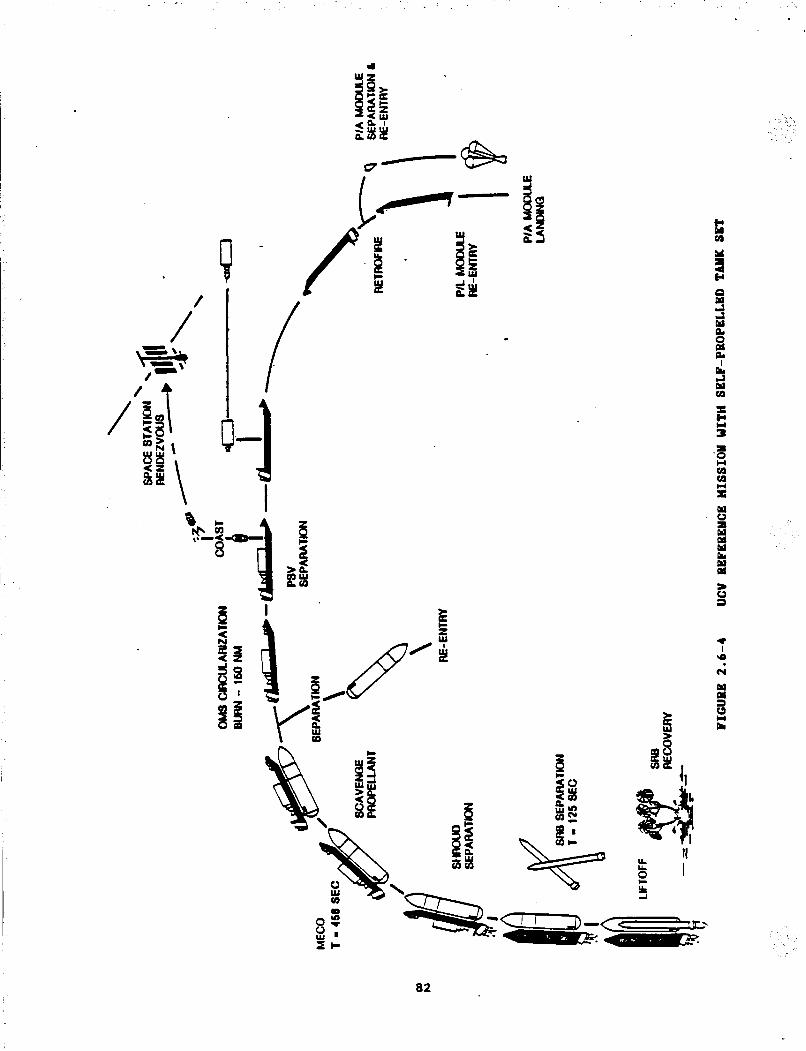
/’ * /
I
a2

I
\
0
H 83
E L
m I
(Y ‘9
5) Tank unit in near cireular 210 x 220 nm orbit; 6) Payload and P/A modules in descending 30 x 190 TUU orbit (minimal OHS
use required for deorbit); and 7 ) Tether saves about 2.6 klb storable bipropellant -- tether system mass
approximately 1.3 klb for a net mass saving of 1.3 klb. For all methods of propellant delivery, the operational impact of
propellant loading is similar. The methods of propellant loading proposed are discussed in Section 2.3.
BFiefly, it is proposed that LHZ loading should take place through the Centaur Rolling Beam System, developed for the STS/Centaur program. LO2 loadins may take place through the P I A module or through a new umbilical at the starboard mid-body. Uo severe operational impact is expected from the propellant loading requirements. The STSKentaur timelines and procedures can form a basis for timeline development.
a4
3.0 REFERENCES . 1. "STS Propellant Scavenging Systems Study - Part XI", Final Report,
Contract NAS8-35614, Hartin Marietta Michoud Aerospace, February 1986
2. "Space Transportation Architecture Study", Special Report Number One (CDRL
023A21, Contract UAS8-36618, Martin Harietta Denver Aerospace, May 1986
3. "Space Transportation Architecture Study", Third Interim Progress Report, Contract UAS8-36618, Martin Marietta Denver Aerospace, June 19, 1986
4. "lamina1 Hission Model (FY 1983 - 20001, Revision 7 (SS), Space Station Advocacy", NASA Marshall Space Flight Center/PSOl, July 1984 .
5. "OW Hission Model - Rev. lo", OTV-86-002(10), UASA Harshall Space Flight Canter/PFZO, February 6, 1987.
6. "Sidemount Unmanned Launch Vehicle (ULV) Costs Study", Final Report,
Contract FO4701-82-C-OU2, Martin Marietta Denver Aerospace, Hichoud Division, August 1984
1
7. "Shuttle Derived Vehicles (SDV) Technology Requirements Study", Volume V, "External Tank Aft Cargo Carrier Study", Phase 11, Final Report, Contract UAS8-34183, Uartin Marietta Denver Aerospace, Hichoud Division, Hay 1982
85

I-
APPENDIX I - DETAILED TAM( SET WEIGHT. BREAKDOWNS This appendix gives de ta i led weight breakdowns for the appendix three
tank set options which were studied for SDV cryogenic propel lant t ransport .
Oution 1: The tank set mounted in the a f t end of the P/L module;
Omtion 2: The tank set mounted in the forward end of the P/L module,
intruding into the nose cone; and
Omtion 2A: Option 2, with the addi t ion of a s to rab le propel lant propulsion system - a self-propelled tank un i t .
All options include two LH2 tanks and one LO2 tank and a r e capable of containing 61.4 klb of cryogenic propel lants a t a mixture r a t i o of 6:l.

. PROPELLANT SCAVENGING VEHICLE
OPTION 1 AFT MOUNTED TAM( SET
GRP ELEMENT WEIGHT
SUlMABY
2.0 Structures 3.0 Propellant Tanks 4 .0 Propulsion 8.0 Communication C Data Handling 9 .0 Electrical Power
10.0 Thermal Control
DRY WEIGHT
15.0 Fluids
Fuel - LX2 Oxidizer - LO2 Helium
TOTAL VEHICLE WEIGHT
(lb) 6 73 872 938
59
35
199
2776
8700
52700
15
64191
A-2

PROPELWIT SCAVENGING VEHICLE OPTIOI 1
APT UO-D TANK SET
. . .
GRP ELmRm WEIGHT
2.0 STRUCTuBeS 2.1 Air Frame
Center Tank Support Clamp Mechanism Struts LO2 Tank Struts LHZ Tanks Attach Hardware Aft Support Frame A t t a c h Hardware
Contingenc y 2.3 Equipment Mounts
Avionics Electrical Propellant Plumbing & Valves Pressurization System V e n t system Contingency
2.4 Handling and Storage O W Pickup Arm
Grapple Fitting and OWV Latches
Contingency 3.0 PBOPELUWT TANK
3.1 Tank Structure Lo2 (1) LHZ (2) Contingency
3.2 Tank Mounts LO2
WIZ Contingency
6 73
493
266 38 14
22 12 64 23
64
50 5 4 18 15 3 5
130 64 49
17 8 72
a22
291 456
75
15 30
5
50
A-3

PROPELLANT SCAVENGING VEHICLE OPTIOU 1
AFT MOUNTED TANK SET
GRP ELEMDIT WEIGHT
4 . 0
4 . 1
4 .2
4.3
4 .4
4 . 5
4 .6
PROPULSIOU Pressurant and Pneumatic System
Valves (20)
Regulators Lines and Attachments Helium Spheres
Contingency
Propellant FV&D h e 1 Valves (16)
Lines, Bellows, Disconnects Cont ingency
Propellant EV&D Oxygen-
Valves ( 8 )
Lines, Bellows, Disconnects
Contingency R o p Utilization & Management System
Channels Screens Perforated Plates Standpipes and Nozzles Attach Hardware Contingency
Vent System (Uonpropulsive) Valves (3 )
Lines, Vent I/F & Attach Hardware
Contingency
Umbilicals Umbilicals Contingency
26
9
20
9 0
22
64
100
25
32
3 1
10
150
10
28
60
50
45
24
60
13
60
9
938
16 7
189
73
343
97
69
A-4

PROPELLANT SCAVENGING VEHICLE OPTIOI 1
AFT MOUNTED TAM( SET
WEIGHT
8 .0
8 . 1
9.0 9.5
10.0
10.1
10.2
COWLIICIPICATIOU MID DATA HAUDLIISG
Communiea t ion Transponder
Power Amplifier Antennas/Switches (2)
Instrumentation Contingency
ELECTRICAL wwea Power Distribution
Batteries
. Wiring Cont ingemcy
TH- COrnOL
Insulation w - H L I w - SLA Lo2 - M I Contingency
Thermal Control Propulsion Lines Electrical System Instmamentation (Htr Tape)
Contingency
59 59
25
6
10
10 8
3s
3s
20 10
5
199 179
33 96 27 23
20
7
5
5
3
. .. - .
. . . . -
A-S

PROPELLANT SCAVENGING VEHICLE OPTION 1
AFT MOUNTED TANK SET
GRP ELELIENT WEIGHT
15.0 PROPELLANTS 61400 15.1 Propellants 61400
LH2 8700
LO2 52700
A-b

. PROPELLANT SCAVEIJGIHG VEHICLE OPT1013 2
FORWARD MOUNTED TANK SET
GRP eLm4EIiT WEIGHT
SUMUBY
-2.0 Structures
3.0 Propellant Tanks 4.0 Propulsion 8.0 Coumunication and Data Handling 9.0 Electrical Power
10.0 Thermal Control
(lb) 600
913
938
59
35
199
15.0
DRY WEIGHT
Fluids Fuel - LH2 Oxidizer - LO2 Helium
. TOTAL VEHICLE WEIGHT
2744
8700
52700
u
64159
C
I .
&-7

. _
PROPELLANT SCAVEWGIWG VEHICLE OPTIOW 2
FORWARD MOUNTED TAM( SET
GRP E L E " I WEIGHT
2.0
2.1
2.3
2.4
3.0
3.1
3.2
STRUCTURE Airf r8me
Forward Support Frame Center Ring Frame LH2 Tank Center Support LH2 Tank End Support
LO2 Tank S t r u t s
LH2 Tank S t r u t s
Attach Hardware
Contingency
Equipment Mounts Avionics
Propellant Plumbing and Valves Pressurization System vent System
Electrical
Contingency
Handling and Storage O W Pickup A m Grapple P i t t i n g and OKL Latches
Contingency
PROPELLANT TAM(
Tank Structure
Lo2 (1) LH2 (2) Contingency
Tank Mounts
LO2 Tank Mounts
LH2 Tank Mounts
LH2 Tank Trunnions
Contingency
6 00 411
41
29 85 136 22 14 30 54
50
5
18 u
3
4
5
. 159 89
49 21
9 13
822 291 456 75
91 24
52
7
8

GRP ELEMEm!
PROPELLANT SCAVENGING VEHICLE OPTIOt? 2
FORWAFtD MOUNTED TAM( SET
WEIGHT
4.0
4.1
4.2
4.3
4 . 4
4 .s
PBOPutSIOl Pressurant and Pneumatic Systems
Valves ( 2 0 )
Regulators
Lines and Attachments Helium Spheres Contingency
Propellant FVdD Fuel V a l v e s (16)
Lines, Bellows, Disconnects Contingency
Propellant W&q Oxygen Valves (8) Lines, Bellows, Disconnects
Contingency t
Prop Utilization and Management System
Channels Screens Perforated Plates Standpipes and Nozzles Attach Hardware Contingency
Vent System (Nonptopulsive) Valves (3) Lines, Vent I/F and Attach Hardware Contingency
938 16 7
6
9
20
90
22
189
64
100 25
.3 2
31
10
343
150
10 28 60
50 45
73
97
24
60
13
. . " 'j - .
A-9

PROPELLANT SCAVENGING VEHICLE OPTIOU 2
FORWARD MOUUTED TANK SET
GRP ELE”I WEIGHT
4.6 Umbilicals
Umbilicals Contingency
8.0 COMMUUICATIOU MID DATA “IDLING 8.1 Cammunication
Transponder Power Amplifier Antennas/Switches (2) Instrumentation Contingency
9.0 ELECTRICAL POWEB 9.5 Power Distribution
Batteries Wiring Contingency
10.0 -THERMAL COUTROL 10.1 Insulation
LH2 - t4LI LH2 - SLA LO2 - M I
Contingency 10.2 Thermal Control
Propulsion Lines
Electrical System Instrumentation (Htr Tape) Contingency
69
60
9
59 59
2s
6 10
10 8
35 35
.20
10
5
199 179
33 96
27
23 20
7
5
5 3
A-10
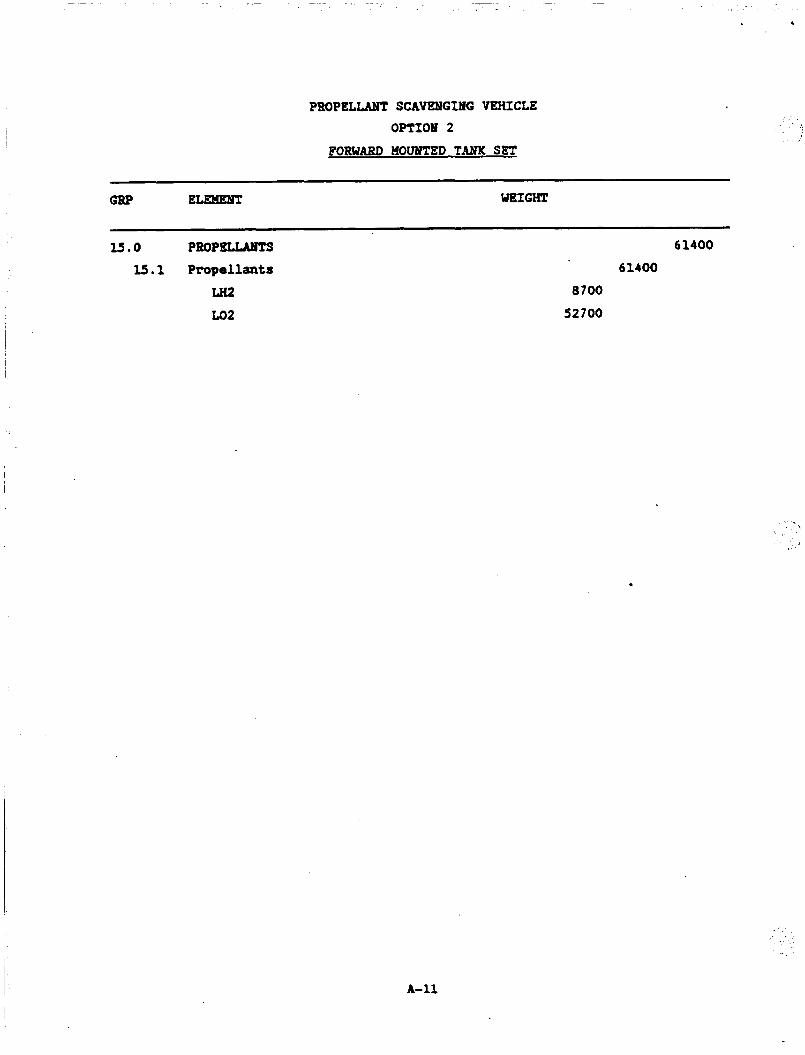
PROPELLMIT SCAVENGING VEHICLE OPTIOP 2
FORWARD UOUNTED TAM< SET
WIGHT
_ _ _ _ _ _ ~
l5.0 PBOPeuMlTS I5 .l Propellants
LHZ Lo2
61400 61400
8700
52700
A-11

PROPELLANT SCAVENGING VEHICLE OPTION 2A
SELF-PROPELLED TANK SET
GRP EL- WEIGHT
SUlQuBY 2.0 S t m c tures
(lb) 597
3.0 4.0
5.0
6.0
7.0
8 . 0
9 .0
10.0
Propellant Tanks Prop Is ion Main Engines Reaction Control System Guidance Uavigation Control Communication and Data Handling Electrical Power Thermal Control
1322 1034
56
130 54 100 35
202
DRY WEIGHT 3530
12.0 Propellants
Uon Propulsive
€bel - LHZ o m e n - LO2
61400
8700
52700
Propulsive ~ / U 2 0 2 3160
68090 INERT WEIGHT
A-12
I

I PBOPEl,,LAHT SCAVENGING VEHICLE OPTION 2 8
SELF-PROPELLED TANK SET
GRP EL- WEIGHT
2 .0 STBuCTuBe
2 . 1 Airfraam Forward Support Frame Center Ring 'Frame LHZ Tank Center Support LHZ Tank End Support LO2 Tank Struts LIi2 Tank Struts Attach Hardware Contingency
2 .2 Thrust Structure Engine Truss Contingency
2.3 Equipment Mounts REMS
Avionics Electrical Vent System Pressurization System
Propellant Plumbing and Valves
Contingency 2.4 Handling and Storage
RHS Grapple Fitting O W Latches PSV Spring Latch Contingency
597
411 41
29
85
136
22
14
30
54
28
25
3
77
10
18
6
3
15
18
7
81 28
20
25
7
. . - .
. .
A-13

PROPELLANT SCAVENGING VEHICLE OPTION 28
SELF-PROPELLED TANK SET
GRP ELEHENT WEIGHT
3.0 PROPELLANT TMTKS 3.1 Tank Structure 3.1.1 lon-Propulsion Tanks
Lo2 (1)
Ln2 (2) Contingency
3.1.2 Propulsion Tanks E202 (2)
MM (2) Contingency
3.2 Tank Mounts 3.2.1 Bon-Propulsion Tank
LO2 Tank Mounts LH2 Tank Mounts
Ln2 Tank Trunnions Coniingency
3.2.2 Propulsion Tank N202 Mounts EMH Mounts Contingency
1322 1143
822 291
456 75
321 146 146 29
179 91
24 52 7 8
88
40 ’
40
8
6-14

- . . ' . .
- . .
I
PROPELLANT SCAVENGING VEHICLE OPTION 26
SELF-PROPELLED TAM< SET
GRP ELEMEbm WEIGHT
4 .0
4.1
4.2 4.2.1
4.2.2
4.3 4.3.1
4.3.2
4.4
1034 P6#)PULsIOU Pressurant and Pneumatic System8 16 7
Valves (20)
Regulators Lines and Attachmnts Helium Spheres Contingency
Feed Vent 6 Drain Fuel loon Propulsion - Fuel 189
241
Valves 64
Lines, Bellows, Disconnects 100 Contingency 25
Valves and Plumbing 47
Contingency 5
Propulsion - Fuel 52
Feed, Vent 6 Drain Ox Non Propulsion - Ox 73
Valves 32 Lines, Bellows, Disconnects 31
Contingency 10 Propulsion - Ox 44
Valves and Plumbing 40 Contingency 4
Channels 150 Screens 10
Perforated Plates 28 Standpipes and Nozzles 60
Prop Utilization 6 Management System
Attach Hardware 50
Contingency 45
26 9
20 90
22
117
343
A-15

I -
( '
PROPELLANT SCAVEUGING VEHICLE OPTION 28
SELF-PROPELLED TAM( SET
GRP EL- WEIGHT
4 .5
4.6
5 . 0
5 . 1
5 . 2
6 .0
6 . 1
6 . 3
7 .0
7 . 1
Vent System (Bonpropulsive) 97
Valves 24
Lines, Vent I/F and Attach Hardware 60
Contingency 13
Umbilicals Umbilicals 60
Contingency 9
luIB ENGINES
Eng' ines R-40B Engines (2)
Contingency Gimbal System
Electrical Gimbal System Contingency
REACTIOU COUTROL SYSTEM
Thruster R-1E Engines (161 Contingency
Plumbing Plumbing and Valves Contingency
GUIDANCE, UAVIGATION AUD COUTFtOL Guidance and Control
Inertial Reference Unit Reaction Control Driver Contingency
56
31
28
3
25
22
3
130
88
80
8
42
38
4
69
54
54
37
12
5
A-16
-... .

PROPELLANT SCAVENGING VEHICLE OPT1013 28
SELF-PROPELLED TANK SET
ELEMENT WEIGHT GRP
8 . 0 COHMUUICATIOP MID DATA HMIDLIW: 8.1 Conummication
Signal Conditioner Transponder
Power Amplifier Antennas/Switches ( 2 )
Instnnnentation Contingency
100 72
14
25
6
10
10
7
8.2 Data Handling Computer. Contingency
9 . 0 ELECTRICAL POWER
9.5 Power Distribution Batteries Wiring Con t ingenc y
10.0 THERMAL COlOTBOL 10.1 Insulation
w - MLI w - stb Lo2 - MLI Contingency
10.2 Thermal Control Propulsion Lines Electrical System Instrumentation Contingency
28
25
3 -
35
35
20 10
' 5
202
179 33
96
27
23
23
9 5
7
2
t
A-17

PROPELLANT S C A W G I I G VEHICLE OPTION 2A
SELF-PROPELLED TAM( SET
GRP ELEMENT WEIGHT
15.0 PROPELLANTS
15.1 Propellants 15.1.1 lon Propulsive
LH2 Lo2
15.1.2 Propulsive If202 1580.2 lMtf
64560 64560
61400 a700 52700
3160 3160
A-10