Embed Size (px)
Citation preview

Revision P Page 1 of 44
HyPerformance Plasma System
Serial Interface Protocol And
CNC Signal Listing

Revision P Page 2 of 44
Revision History Revision Date Description N 07.01.2008 Release of HPR400
- Command ID 095 accepts up to 400 amps - Table VI – Gas Type Code: Gas type #7 changed from CO2 to Argon - Command ID 114 added inputs for HPR400 choppers signals - Command ID 133 added analog values for HPR400 choppers (current,
temperature) - Command ID 134 added error code log for last 4 errors since system power up - Command ID 135 added for production CAN test fixture - Command ID 000 added “HYPERFORMANCE400XD” as a system identity. - New Error codes: 028 Lost Current Chopper 3 034 Lost Current Chopper 4 073 Chopper 3 Overtemp 074 Chopper 4 Overtemp 075 LEM 3 Current Low 076 LEM 4 Current Low 095 LEM 4 Current High 107 LEM 3 Current High 146 Chopper 3 Overtemp at Init 147 Chopper 4 Overtemp at Init 154 Chopper 3 Over current 155 Chopper 4 Over current 157 Chopper 3 Current at Init 158 Chopper 4 Current at Init 159 Motor Drive Fault 160 HPR Cooler CAN Fault
M 11.10.2009 Added serial command ID #136, to enable a serial response delay time. See serial interface guidelines.

Revision P Page 3 of 44
Table of Contents
I) INTERFACE HARDWARE ........................................................................................................................ 4
II) SIGNAL LIST ............................................................................................................................................ 4
A. HPR SIGNALS .......................................................................................................................................... 4 B. MAXPRO200 HARDWARE ......................................................................................................................... 5 C. HARDWARE ............................................................................................................................................. 5 D. HPR MULTI-DROP WIRING ....................................................................................................................... 6 E. HPR MULTI-DROP ADDRESSING ............................................................................................................... 7
III) SERIAL COMMANDS ............................................................................................................................. 7
A. FORMAT .................................................................................................................................................. 7 B. FRAMING ................................................................................................................................................. 7 C. COMMANDS ............................................................................................................................................. 7 D. ERROR RESPONSES ............................................................................................................................... 38 E. CALCULATING CHECKSUMS .................................................................................................................... 39
IV) ERROR CODES .................................................................................................................................... 39
V) STATE CODES ...................................................................................................................................... 42
VI) GAS TYPE CODES ............................................................................................................................... 43
VII) SERIAL INTERFACE GUIDELINES .................................................................................................... 44
VIII) APPLICATION NOTES ....................................................................................................................... 44

Revision P Page 4 of 44
I) Interface Hardware i. The interface will use a combination of discrete signals and an RS422 interface.
II) Signal List
a. HPR Signals
Signal Name Type Description
Plasma Start Input When active the plasma system will fire an arc
Machine Motion 1 Output Indicates the arc has transferred to the plate. This signal is selected using jumper on power supply control board. Only 1 motion signal is needed per system. The remaining motion signals can be used to daisy chain wire multiple systems.
Machine Motion 2 Output Indicates the arc has transferred to the plate. This signal is selected using jumper on power supply control board. Only 1 motion signal is needed per system. The remaining motion signals can be used to daisy chain wire multiple systems.
Machine Motion 3 Output Indicates the arc has transferred to the plate. This signal is selected using jumper on power supply control board. Only 1 motion signal is needed per system. The remaining motion signals can be used to daisy chain wire multiple systems.
Machine Motion 4 Output Indicates the arc has transferred to the plate. This signal is selected using jumper on power supply control board. Only 1 motion signal is needed per system. The remaining motion signals can be used to daisy chain wire multiple systems.
Hold Ignition Input When active system will stay in preflow and delay torch ignition. This signal should be applied the same time the start signal is applied.
System Error Output Indicates that an error has occurred in the plasma system. Use the serial interface to query for the specific error code number.
Pierce Complete Input When active the system will use shield preflow gases during piercing. When the signal is removed, it will switch to shield cutflow gases. This signal should be applied at the same time the start signal is applied.
Corner Current Input When active the system will switch to user specified corner current.
Remote Power Input This signal is used to turn the power on or off
Not Ready For Start Output When active, this signal indicates that the plasma system is not ready for a plasma start signal. This could be because the system is purging or in test gas mode.
Rampdown error Output Indicates the arc did not rampdown properly. Consumable life is affected.
TX+ Serial Transmitting from the system.
Revision P Page 5 of 44
Connect to CNC RX+
TX- Serial Transmitting from the system.
Connect to CNC RX-
RX+ Serial Receiving by the system.
Connect to CNC TX+
RX- Serial Receiving by the system.
Connect to CNC TX-
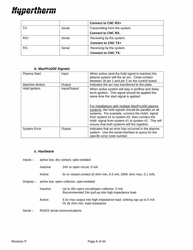
b. MaxPro200 Signals Plasma Start Input When active (and the hold signal is inactive) the
plasma system will fire an arc. Close contact between J6 pin 1 and pin 2 on the control board
Machine Motion Output Indicates the arc has transferred to the plate. Hold Ignition Input/Output When active system will stay in preflow and delay
torch ignition. This signal should be applied the same time the start signal is applied.
For installations with multiple MaxPro200 plasma systems, the hold signals should be parallel on all systems. For example, connect the Hold+ signal from system #1 to system #2, then connect the Hold- signal from system #1 to system #2. This will ensure that both systems will fire together.
System Error Output Indicates that an error has occurred in the plasma system. Use the serial interface to query for the specific error code number.
c. Hardware Inputs – active low, dry contact, opto-isolated Inactive: 24V or open circuit, 0 mA Active: 0v or closed contact (0 ohm min, 6.5 mA; 200K ohm max, 0.1 mA)
Outputs – active low, open collector, opto-isolated Inactive: Up to 40v open circuit/open collector, 0 mA Recommended 24v pull-up into high impedance load Active: 0.3v max output into high impedance load, sinking cap up to 5 mA Or 2k ohm min. load resistance
Serial – RS422 serial communications

Revision P Page 6 of 44
d. HPR Multi-Drop Wiring Plasma Start Hold Ignition Pierce Complete --DB37 Corner Current Machine Motion 1 Machine Motion 2 Machine Motion 3 Machine Motion 4 System Error Rampdown Error RS 422 Serial Remote Power On/Off HPR System 1 CNC
Remote Power On/Off HPR System 2
Remote Power On/Off
HPR System 3 Remote Power On/Off HPR System 4

Revision P Page 7 of 44
e. HPR Multi-drop Addressing The power supply control has dipswitches to set the power supply ID. Dipswitch 2,3,4 are used to set the ID. 2 3 4 ID Off Off Off 0 On Off Off 1 Off On Off 2 On On Off 3 Off Off On Reserved On Off On Reserved Off On On Reserved On On On Reserved Systems with ID 0 power up with the serial interface enabled. Systems with any other ID power up with the serial interface disabled. To implement the multi-drop interface the CNC must send the SLEEP command (086) which will put all systems on the line into sleep mode. The WAKE command (085) with specific system ID will wake the system the CNC wants to communicate with. Any command can now be sent to that power supply, all other systems will ignore the communications. When the CNC is finished communicating with that power supply the SLEEP command must be sent, then the WAKE command is used to talk with the next system.
III) Serial Commands
a. Format ASCII based protocol Baud 19200 8 Data bits 1 Stop bit No parity No flow control
b. Framing > = Start of message 3 byte command ID Data 2 byte checksum < = End of message
Sample: >0011C2<
c. Commands Responses will echo the ID of the command, unless there is an error in the command.

Revision P Page 8 of 44
Command Table
ID Command System Description 000 HELLO
Manual Gas System Auto Gas System MaxPro200
Establish communications with the plasma system. Use this command to identify which system you are talking to. Data: None Return Value: String identifying the system Sample: >00090< >000HYPERFORMANCE130MANUALB5< or >000HYPERFORMANCE130AUTO30< or >000HYPERFORMANCE130AUTOMIX1E< or >000MaxPro20079<
001 VERSION Manual Gas System Auto Gas System MaxPro200
Get the version of the power supply firmware Data: None Returned Value: Power supply firmware then Gas console firmware, space delimited Sample: >00191< >001A.0 A.25< (ps rev A, gas rev A)
002 GET_STATE
Manual Gas System Auto Gas System MaxPro200
Get the current state of the plasma system. Data: None Return Value: Status code (see table V) Sample: >00292< >002000052< (status code 0)
003 CURRENT_ERROR Manual Gas System Auto Gas System MaxPro200
Get the current system error. Data: None Return Value: Error code (see table IV) Sample: >00393< >00301165B< (error code 116)

Revision P Page 9 of 44
ID Command System Description 004 REMOTE_MODE Manual Gas System
Auto Gas System MaxPro200
Switch system into remote mode, to allow remote control of the plasma system. Data: None Return value: 1 = accepted, 0 = not accepted Sample: >00494< >0041C5<
028 READ_PLASMA_AMPS
Manual Gas System Auto Gas System
Read actual power supply current Data: None Return value: Power supply current in amps Sample: >0289A< >02801305E< (130 amps)
058 SET_NOMINAL_AMPS
Auto Gas System MaxPro200
Set the power supply current in amps. Same for HPR and MaxPro200 Data: 5-400 Amps (Limited to 130 amps on the HPR130, and 260 on the HPR260, and 200 amps on the MaxPro200) Return value: Actual current value set Sample: >05813031< >058013061< (set 130 amps)
064 GAS_PREFLOW_TEST_START Manual Gas System Auto Gas System
Turn on the preflow gases. Not allowed when cutting. Data: None Return value: 1 = accepted, 0 = not accepted Sample: >0649A< >0641CB<

Revision P Page 10 of 44
ID Command System Description 065 GAS_PREFLOW_TEST_STOP Manual Gas System
Auto Gas System Turn off the preflow gases. Not allowed when cutting. Data: None Return value: 1 = accepted, 0 = not accepted Sample: >0659B< >0651CC<
066 GAS_CUTFLOW_TEST_START
Manual Gas System Auto Gas System
Turn on the cutflow gases. Not allowed when cutting. Data: None Return value: 1 = accepted, 0 = not accepted Sample: >0669C< >0661CD<
067 GAS_CUTFLOW_TEST_STOP Manual Gas System Auto Gas System
Turn off the cutflow gases. Not allowed when cutting. Data: None Return value: 1 = accepted, 0 = not accepted Sample: >0679D< >0671CE<
068 SOFTWARE_RESET Manual Gas System Auto Gas System MaxPro200
HPR: Clear error conditions and resume operation. Only accepted if system is in a shutdown error condition (Error code > 79 and State = 14). MaxPro200: This command is only valid when the system is not cutting. This command will clear all errors and reset the system to the power up state and resume error checking. This command is not intended to stop plasma cutting and is not active when the arc is on. Data: None Return value: 1 = accepted, 0 = not accepted Sample: >0689E< >0681CF<
Revision P Page 11 of 44
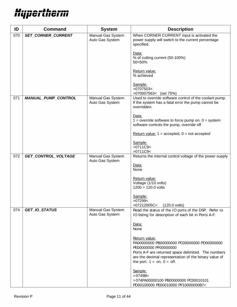
ID Command System Description 070 SET_CORNER_CURRENT
Manual Gas System Auto Gas System
When CORNER CURRENT input is activated the power supply will switch to the current percentage specified. Data: % of cutting current (50-100%) 50=50% Return value: % achieved Sample: >0707503< >070007563< (set 75%)
071 MANUAL_PUMP_CONTROL Manual Gas System Auto Gas System
Used to override software control of the coolant pump. If the system has a fatal error the pump cannot be overridden. Data: 1 = override software to force pump on, 0 = system software controls the pump, override off Return value: 1 = accepted, 0 = not accepted Sample: >0711C9< >0711C9<
072 GET_CONTROL_VOLTAGE
Manual Gas System Auto Gas System
Returns the internal control voltage of the power supply Data: None Return value: Voltage (1/10 volts) 1200 = 120.0 volts Sample: >07299< >07212005C< (120.0 volts)
074 GET_IO_STATUS Manual Gas System Auto Gas System
Read the status of the IO ports of the DSP. Refer to IO listing for description of each bit in Ports A-F. Data: None Return value: PA00000000 PB00000000 PC00000000 PD00000000 PE00000000 PF00000000 Ports A-F are returned space delimited. The numbers are the decimal representation of the binary value of the port. 1 = on, 0 = off. Sample: >0749B< >074PA00000100 PB00000000 PC00010101 PD00100000 PE00010000 PF10000000B7<

Revision P Page 12 of 44
ID Command System Description 078 SET_ALL_GAS_FLOWS
Auto Gas System MaxPro200
Set all gas flow rates. N2 mix setpoint and Gas 2 mix setpoint are only applicable when using a mixed plasma gas such as H35 – N2 otherwise these 2 values should be set to 0. A value of 0 for N2 Mix Setpoint will cause the system to close sv12, the solenoid valve for N2 mixing. A value of 0 for Gas 2 Mix Setpoint will cause the system to close sv13 and open sv14. This will cause the inlet gas to bypass motor valve 2 and pass directly to the outlet of the mixing console. HPR
Data (space delimited): Space delimited: Plasma cutflow setpoint (0 –99 psi), Plasma preflow setpoint (0 – 99 psi), Shield cutflow setpoint (0 – 99 psi), Shield preflow setpoint (0 – 99 psi), N2 Mix Setpoint (0 – 100 psi), Gas2 Mix Setpoint (0 – 100 psi). Returned value: 1 = accepted, 0 = not accepted
MaxPro Data (space delimited); Plasma Pressure Setpoint (“0050”) Shield Pressure Setpoint (“0058”)
Sample: >07855 45 35 25 50 50AB< >0781D0<

Revision P Page 13 of 44
ID Command System Description 079 GET_PS_INFO
Manual Gas System Auto Gas System MaxPro200
Returns pressures, system state, and system error, space delimited Data: None HPR Return value: Plasma Cutflow Pressure (0044 = 44psi) Plasma Preflow Pressure (0044 = 44psi) Shield Cutflow Pressure (0044 = 44psi) Shield Preflow Pressure (0044 = 44psi) Current Setpoint (amps) System State (see table V) (0003 = state 3) System Error (see table IV) (0000 = error 0) Cut Gas 1 Pressure (0044 = 44psi) Cut Gas 2 Pressure (0044 = 44psi) N2 Mix Inlet Pressure (0044 = 44psi) Gas2 Mix Inlet Pressure (0044 = 44psi) Note: Cut gas 1, Cut gas 2, N2 mix Inlet, and Gas 2 mix Inlet are not measured in the Manual gas console configuration. MaxPro200 Return value: System State (see table V) (“st0003”) System Error (see table IV) (“er0000”) Plasma Gas Type Code (see table VI) (“pg0001”) Plasma Pressure Setpoint (“ps0056”) Shield Gas Type Code (see table VI) (“sg0001”) Shield Pressure Setpoint (“ss0058”) Current Setpoint (“cs0200”) Display Mode(“dm0001”) 0=Current 1=Error/Status 2=Coolant flow 3=Test Mode Lock Mode(“lm0001”) 1=display is locked, 0=unlocked Sample: >079A0< >079PC0044 PP0042 SC0034 SP0035 CS0040 ST0003 ER0000 CG0000 CG0000 MV0000 MV0000DE< *********************************************************** For Factory Testing Only *********************************************************** Auto Gas Control Board N2M – N2 Mix Setpoint (psi) G2M – Gas 2 Mix Setpoint (psi) ST - System state (state code) ER – System Error (error code) P1P5 – Pressure input (psi) P2P6 – Pressure input (psi)
Split command GET_INFO2 (ID#126)
Revision P Page 14 of 44
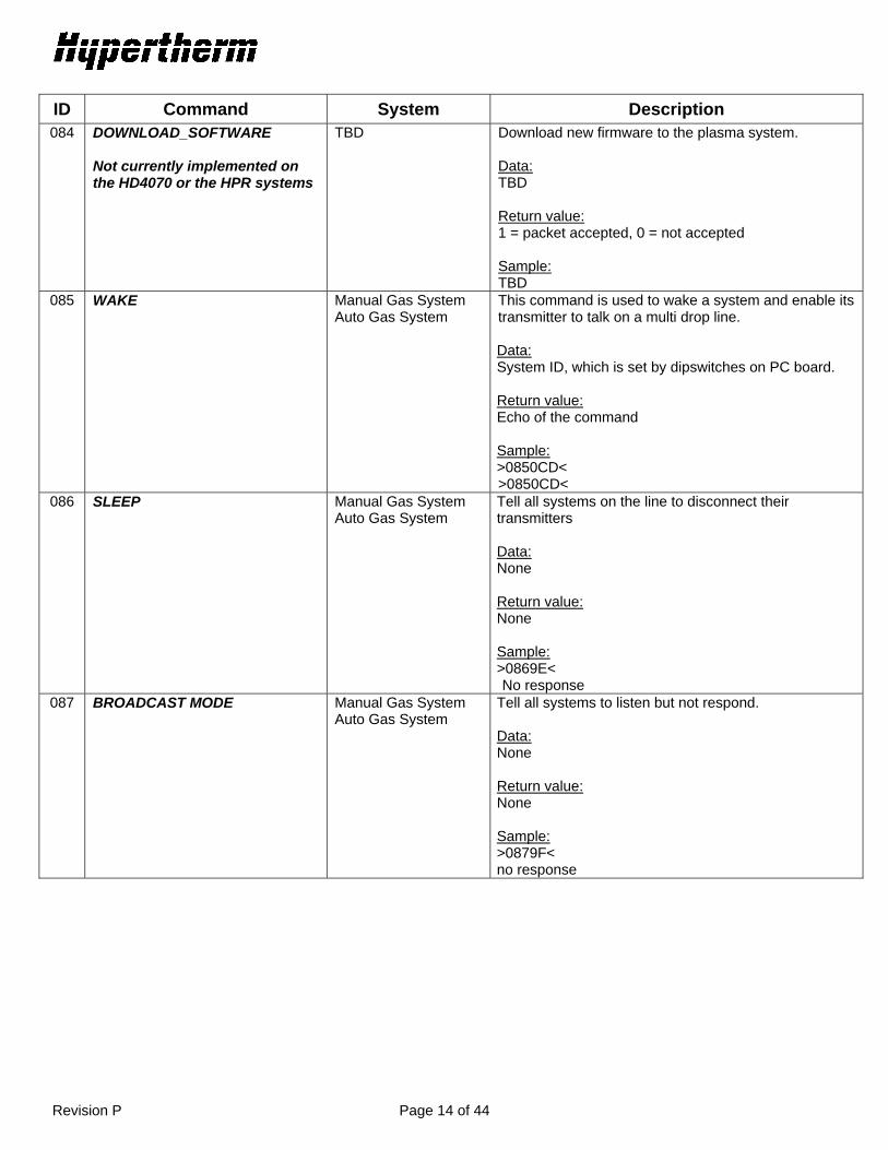
ID Command System Description 084 DOWNLOAD_SOFTWARE
Not currently implemented on the HD4070 or the HPR systems
TBD Download new firmware to the plasma system. Data: TBD Return value: 1 = packet accepted, 0 = not accepted Sample: TBD
085 WAKE Manual Gas System Auto Gas System
This command is used to wake a system and enable its transmitter to talk on a multi drop line. Data: System ID, which is set by dipswitches on PC board. Return value: Echo of the command Sample: >0850CD< >0850CD<
086 SLEEP Manual Gas System Auto Gas System
Tell all systems on the line to disconnect their transmitters Data: None Return value: None Sample: >0869E< No response
087 BROADCAST MODE Manual Gas System Auto Gas System
Tell all systems to listen but not respond. Data: None Return value: None Sample: >0879F< no response
Revision P Page 15 of 44
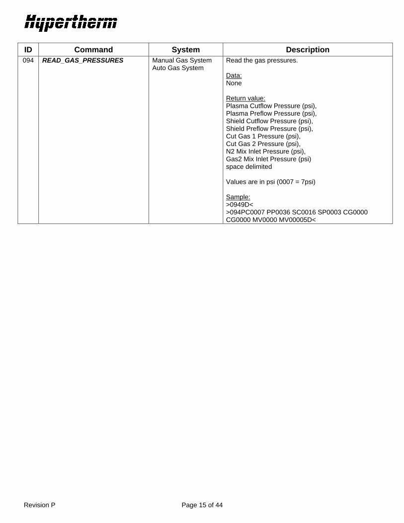
ID Command System Description 094 READ_GAS_PRESSURES
Manual Gas System Auto Gas System
Read the gas pressures. Data: None Return value: Plasma Cutflow Pressure (psi), Plasma Preflow Pressure (psi), Shield Cutflow Pressure (psi), Shield Preflow Pressure (psi), Cut Gas 1 Pressure (psi), Cut Gas 2 Pressure (psi), N2 Mix Inlet Pressure (psi), Gas2 Mix Inlet Pressure (psi) space delimited Values are in psi (0007 = 7psi) Sample: >0949D< >094PC0007 PP0036 SC0016 SP0003 CG0000 CG0000 MV0000 MV00005D<

Revision P Page 16 of 44
ID Command System Description 095 SET_ALL_PARAMETERS
Auto Gas System MaxPro200
Set all variables to run the plasma system. If inlet gases change power supply will enter the purge state. Gas type changes are not allowed when the system is cutting (state 4 – state 10). HPR N2 mix setpoint and Gas 2 mix setpoint are only applicable when using a mixed plasma gas such as H35 – N2 otherwise these 2 values should be set to 0. A value of 0 for N2 Mix Setpoint will cause the system to close sv12, the solenoid valve for N2 mixing. A value of 0 for Gas 2 Mix Setpoint will cause the system to close sv13 and open sv14. This will cause the inlet gas to bypass motor valve 2 and pass directly to the outlet of the mixing console. Data: Current setpoint (5 – 130/260/400 amps), corner current percent (50 - 100%), plasma gas type code (use table VI), shield gas type code (use table VI), plasma cutflow setpoint (0 – 99 psi), plasma preflow setpoint (0 – 99 psi), shield cutflow setpoint ( 0 – 99 psi), shield preflow setpoint (0 – 99 psi), N2 mix setpoint (0 – 100 psi), Gas 2 mix setpoint (0 – 100 psi), space delimited.
Return value: 1= accepted, 0 = not accepted MaxPro200 **It is recommended to use command #137 to set the process for MaxPro200 systems, refer to that command for more information** Data: Current Setpoint in amps (0-200) Plasma Gas Type Code (use table VI) Shield Gas Type Code (use table VI) Plasma Pressure Setpoint in psi (0 – 99) Shield Pressure Setpoint in psi (0 – 99) Return value: 1= accepted, 2 = data invalid or system not in state #2 or #3
Sample: >095100 75 1 6 55 45 35 25 00 0084< >0951CF<

Revision P Page 17 of 44
ID Command System Description 096 SET_INLET_GASES
Auto Gas System MaxPro200
Set inlet gases for auto console. If inlet gases change power supply will enter the purge state. Gas type changes are not allowed when the system is cutting (state 4 – state 10). Data: Plasma gas type code (See table VI), Shield gas type code (See table VI), space delimited. Return value: 1= accepted, 0 = not accepted Sample: >0961 626< (Set plasma gas = O2 and set shield gas = N2) >0961D0<
097 READ_CORNER_CURRENT
Manual Gas System Auto Gas System
Read the corner current percentage Data: None Return value: Percentage Sample: >097A0< >09700756C< (75%)
098 GET_INLET_GASES
Manual Gas System Auto Gas System MaxPro200
Read the inlet gas types Data: None Return value: Plasma gas type code (See table VI), Shield gas type code (See table VI), space delimited *For some marking processes using N2 or Argon as the marking gas, the system may override the shield gas type code for optimum system performance. This could include changing the shield gas type code to 9, 10, or 12. It could also include using the shield gas type code from the previous cutting process. Sample: >098A1< >0980001 000648< (plasma gas = O2 and shield gas = N2)

Revision P Page 18 of 44
ID Command System Description 099 GET_GAS_FLOWS
Auto Gas System Read the gas setpoints Data: None Return value: Plasma cutflow setpoint (psi), Plasma preflow setpoint (psi), Shield cutflow setpoint (psi), Shield preflow setpoint (psi), N2 Mix setpoint (psi), Gas2 Mix setpoint (psi) space delimited. (55 = 55psi) Sample: >099A2< >0990055 0045 0035 0025 0050 0050EE<
Revision P Page 19 of 44
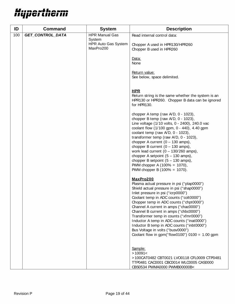
ID Command System Description 100 GET_CONTROL_DATA
HPR Manual Gas System HPR Auto Gas SystemMaxPro200
Read internal control data: Chopper A used in HPR130/HPR260 Chopper B used in HPR260 Data: None Return value: See below, space delimited. HPR Return string is the same whether the system is an HPR130 or HPR260. Chopper B data can be ignored for HPR130. chopper A temp (raw A/D, 0 - 1023), chopper B temp (raw A/D, 0 - 1023), Line voltage (1/10 volts, 0 - 2400), 240.0 vac coolant flow (1/100 gpm, 0 - 440), 4.40 gpm coolant temp (raw A/D, 0 - 1023), transformer temp (raw A/D, 0 - 1023), chopper A current (0 – 130 amps), chopper B current (0 – 130 amps), work lead current (0 – 130/260 amps), chopper A setpoint (5 – 130 amps), chopper B setpoint (5 – 130 amps), PWM chopper A (100% = 1070), PWM chopper B (100% = 1070). MaxPro200 Plasma actual pressure in psi (“plap0000”) Shield actual pressure in psi (“shap0000”) Inlet pressure in psi (“icrp0000”) Coolant temp in ADC counts (“colt0000”) Chopper temp in ADC counts (“chpt0000”) Channel A current in amps (“chac0000”) Channel B current in amps (“chbc0000”) Transformer temp in counts (“xfmr0000”) Inductor A temp in ADC counts (“inat0000”) Inductor B temp in ADC counts (“inbt0000”) Bus Voltage in volts (“busv0000”) Coolant flow in gpm(“flow0100”) 0100 = 1.00 gpm Sample: >10091< >100CAT0482 CBT0021 LVO0118 CFL0009 CTP0481 TTP0481 CAC0001 CBC0014 WLC0005 CAS0000 CBS0534 PWMA0000 PWMB00000B<

Revision P Page 20 of 44
ID Command System Description 101 SET_IO_STATUS
Manual Gas System Auto Gas System MaxPro200
This command will allow the user to turn on or off each output of the processor. After sending this command, the SYSTEM_RESET command must be issued to restore the processor state. The IO are in the following order: Data: 1 = On, 0 = Off for each IO point Return value: 1 = accepted, 0 = not accepted HPR Power Supply Pilot Arc Relay Marking Surge Relay Pilot Arc Enable Coolant Pump Motor Soft Start Enable (HPR130/260 only) CNC Error CNC Rampdown Error Igniter Contactor CNC Machine Motion CNC Not Ready For Start Spare Output Motor Drive Enable MaxPro200 Power Supply CNC Machine Motion Hold Ignition Output CNC Error Contactor Torch Valve Igniter Coolant Pump Motor Pilot Arc Enable Sample: >10111111111111110D< = All outputs on >1011C3< ******************************** Data listed below is for factory testing only ******************************** Manual Gas Console Shield Cutflow (SV 16) Calibrate Bypass (SV 13) Plasma Cutflow 1 (SV 14) Rampdown Valve (SV 20) Shield Preflow (SV 17) Plasma Preflow (SV 18) Plasma Cutflow 2 (SV 19) H35 Plasma Cutflow 2 (SV 12) Spare Valve (SV 15) O2 Shield Cutflow (SV 4) Air Shield Cutflow (SV 5) N2 Shield Cutflow (SV 6) Air Preflow (SV 7)

Revision P Page 21 of 44
ID Command System Description 101 Continued N2 Plasma Cutflow (SV 11)
Sample: >1011111111111111111111166< >1011C3< Auto Gas Console O2 Inlet (SV1) Air Inlet (SV 2) Air Inlet 2 (SV 3) H5 Inlet (SV 4) H35 Inlet (SV 5) F5 Inlet (SV 6) Burkert#1 on 50 psi (B1) Rampdown Valve (SV 16) Spare Out 2 (Spare) Gas 2 No Mix (SV 14) Gas 2 Mix (SV 13) N2 Mix (SV 12) N2 Inlet 2 (SV 11) Air Inlet 3 (SV 10) N2 Inlet (SV 9) O2 Air Inlet (SV 8) CH4 Inlet (SV 7) Burkert#2 on to 50 psi (B2) Burkert#3 on to 50 psi (B3) Burkert#4 on to 50 psi (B4) MV1 Open 1 = activate, 0 = deactivate MV1 Close MV2 Open MV2 Close
Revision P Page 22 of 44
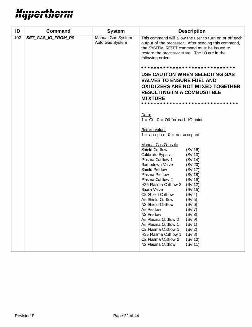
ID Command System Description 102 SET_GAS_IO_FROM_PS Manual Gas System
Auto Gas System This command will allow the user to turn on or off each output of the processor. After sending this command, the SYSTEM_RESET command must be issued to restore the processor state. The IO are in the following order: ****************************** USE CAUTION WHEN SELECTING GAS VALVES TO ENSURE FUEL AND OXIDIZERS ARE NOT MIXED TOGETHER RESULTING IN A COMBUSTIBLE MIXTURE ******************************* Data: 1 = On, 0 = Off for each IO point Return value: 1 = accepted, 0 = not accepted Manual Gas Console Shield Cutflow (SV 16) Calibrate Bypass (SV 13) Plasma Cutflow 1 (SV 14) Rampdown Valve (SV 20) Shield Preflow (SV 17) Plasma Preflow (SV 18) Plasma Cutflow 2 (SV 19) H35 Plasma Cutflow 2 (SV 12) Spare Valve (SV 15) O2 Shield Cutflow (SV 4) Air Shield Cutflow (SV 5) N2 Shield Cutflow (SV 6) Air Preflow (SV 7) N2 Preflow (SV 8) Air Plasma Cutflow 2 (SV 9) Air Plasma Cutflow 1 (SV 1) O2 Plasma Cutflow 1 (SV 2) H35 Plasma Cutflow 1 (SV 3) O2 Plasma Cutflow 2 (SV 10) N2 Plasma Cutflow (SV 11)

Revision P Page 23 of 44
ID Command System Description 102 Continued Auto Gas Console
O2 Inlet (SV1) Air Inlet (SV 2) Air Inlet 2 (SV 3) H5 Inlet (SV 4) H35 Inlet (SV 5) F5 Inlet (SV 6) Spare Out 1 (Spare) Rampdown Valve (SV 16) Spare Out 2 (Spare) Gas 2 No Mix (SV 14) Gas 2 Mix (SV 13) N2 Mix (SV 12) N2 Inlet 2 (SV 11) Air Inlet 3 (SV 10) N2 Inlet (SV 9) O2 Air Inlet (SV 8) CH4 Inlet (SV 7) Sample: >1021111111111111111111167< >1021C4<
103 STOP_SENDING_CAN Factory testing only
Board level testing for 130/260 amp power supplies, manual gas control board, and auto gas control board
This command is used to instruct a CAN node(power supply control board, manual gas control board, auto gas control board) to stop sending any CAN messages. Data: None Return value: 1 = accepted, 0 = not accepted Sample: >10394< >1031C5<
104 SEND_CAN_REGSTATE Factory testing only
130/260 amp power supply control board
This command will instruct the power supply control board to send a CAN state message to the manual gas console control board. Data: None Return value: 1 = accepted, 0 = not accepted Sample: >10495< >1041C6<
Revision P Page 24 of 44
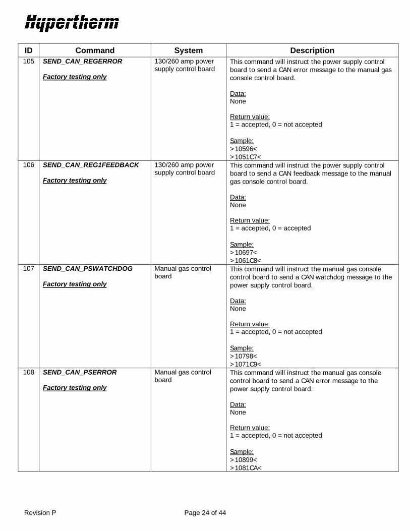
ID Command System Description 105 SEND_CAN_REGERROR
Factory testing only
130/260 amp power supply control board
This command will instruct the power supply control board to send a CAN error message to the manual gas console control board. Data: None Return value: 1 = accepted, 0 = not accepted Sample: >10596< >1051C7<
106 SEND_CAN_REG1FEEDBACK Factory testing only
130/260 amp power supply control board
This command will instruct the power supply control board to send a CAN feedback message to the manual gas console control board. Data: None Return value: 1 = accepted, 0 = accepted Sample: >10697< >1061C8<
107 SEND_CAN_PSWATCHDOG Factory testing only
Manual gas control board
This command will instruct the manual gas console control board to send a CAN watchdog message to the power supply control board. Data: None Return value: 1 = accepted, 0 = not accepted Sample: >10798< >1071C9<
108 SEND_CAN_PSERROR Factory testing only
Manual gas control board
This command will instruct the manual gas console control board to send a CAN error message to the power supply control board. Data: None Return value: 1 = accepted, 0 = not accepted Sample: >10899< >1081CA<

Revision P Page 25 of 44
ID Command System Description 109 SEND_CAN_PSSTATE
Factory testing only
Manual gas control board
This command will instruct the manual gas console control board to send a CAN state message to the power supply control board. Data: None Return value: 1 = accepted, 0 = not accepted Sample: >1099A< >1091CB<
110 SEND_CAN_PS1SETPOINT Factory testing only
Manual gas control board Auto gas control board
This command will instruct the manual gas console control board to send a CAN setpoint1 message to the power supply control board. Data: None Return value: 1 = accepted, 0 = not accepted Sample: >11092< >1101C3<
111 SEND_CAN_PS2SETPOINT Factory testing only
Manual gas control board Auto gas control board
This command will instruct the manual gas console control board to send a CAN setpoint2 message to the power supply control board. Data: None Return value: 1 = accepted Sample: >11193< >1111C4<
112 START_SENDING_CAN Factory testing only
Board level testing for 130/260 amp power supplies, manual gas control board, and auto gas control board
This command is used to instruct a CAN node(power supply control board, manual gas control board, auto gas control board) to resume sending CAN messages. Data: None Return value: 1 = accepted Sample: >11294< >1121C5<
Revision P Page 26 of 44
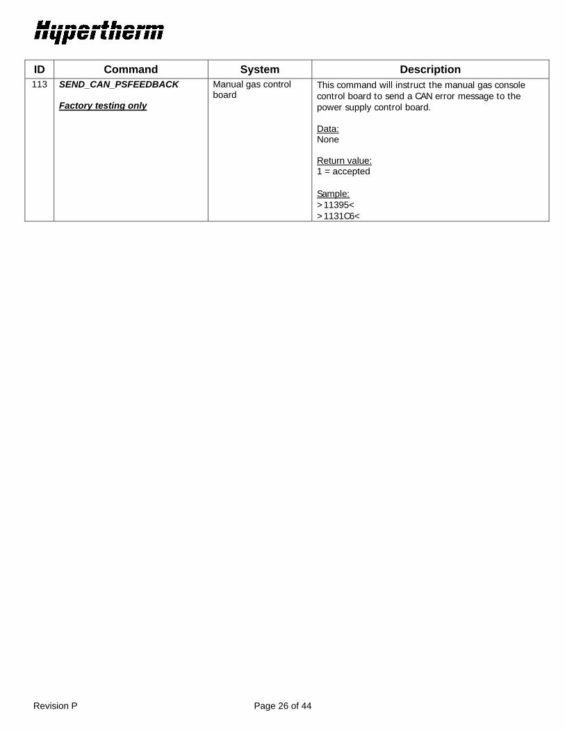
ID Command System Description 113 SEND_CAN_PSFEEDBACK
Factory testing only
Manual gas control board
This command will instruct the manual gas console control board to send a CAN error message to the power supply control board. Data: None Return value: 1 = accepted Sample: >11395< >1131C6<

Revision P Page 27 of 44
ID Command System Description 114 READ_INPUTS
Manual Gas System Auto Gas System MaxPro200
This command will return the status of inputs to the pc board. Data: None Return value: 1 = on, 0 = off HPR Power Supply Serial Program Plasma Start Hold Ignition Phase OK Arc Detect Pierce Complete Corner Current Redundant Start Serial ID0 Serial ID1 Serial ID2 Dipswitch #1 Dipswitch #5 Dipswitch #6 Dipswitch #7 Dipswitch #8 Chopper A Overcurrent Chopper B Overcurrent Chopper C Overcurrent Chopper D Overcurrent IPM Fault MaxPro200 Power Supply Plasma Start Alt Start Hold Ignition Arc Detect Power On Chopper A Overcurrent Chopper B Overcurrent Sample: >11496< >11400000000000000000000086< ******************************** Data listed below is for factory testing only ******************************** Manual Gas Console Spare Dipswitch Encoder Pushbutton Error select Status select Test preflow Test cutflow Serial ID Bit 0 Serial ID Bit 1 Serial ID Bit 2

Revision P Page 28 of 44
ID Command System Description 115 GET_CONTROL1
Factory testing only
Manual Gas System Auto Gas System
Read internal control data, chopper A temp (raw A/D), chopper B temp (raw A/D), Line voltage (volts), coolant flow (1/100 gpm), coolant temp (raw A/D), transformer temp (raw A/D), chopper A current (amps). Data: None Return value: Above info space delimited. Sample: >11597< >115CAT0482 CBT0021 LVO0118 CFL0009 CTP0481 TTP0481 CAC00FF<
116 GET_CONTROL2 Factory testing only
Manual Gas System Auto Gas System
Read internal control data, chopper B current (amps), work lead current (amps), chopper1 setpoint (amps), chopper 2 setpoint (amps), PWM chopper A (100% = 1070), PWM chopper B (100% = 1070), Pressure A (raw A/D), Pressure B (raw A/D). chopper C temp (raw A/D), chopper D temp (raw A/D), chopper C current (amps), chopper D current (amps). Data: None Return value: Above info space delimited. Sample: >11698< >116CBC0014 WLC0005 CAS0000 CBS0534 PWMA0000 PWMB0000 PRSA0000 PRSB000041<

Revision P Page 29 of 44
ID Command System Description 117 READ_GAS_INPUTS_FROM_PS Manual Gas System
Auto Gas System This command will allow the CNC to query the gas console IO by sending the command to the serial port on the power supply control board. Data: None Return value: 1 = on, 0 = off Manual Gas Console Error select Status select Test preflow Test cutflow Serial ID Bit 0 Serial ID Bit 1 Serial ID Bit 2 Auto Gas Console Metering dipswitch 2 Metering dipswitch 3 Metering dipswitch 4 Select dipswitch 1 Select dipswitch 2 Select dipswitch 3 Select dipswitch 4 Metering dipswitch 1 Sample: >11799< >1170000000E9<
118 GAS_DISPLAY_TEST_MODE Factory testing only
Manual Gas System This command is for the manual gas console control board. There are 3 display modes. Data: display mode Mode 0 = run Mode 1 = all displays off Mode 2 = write 0xAA to display bus Mode 3 = write 0x55 to display bus Return value: 1 = accepted, 0 = not accepted Sample: >1180CA< >1181CB<
119 PS_ONLY_TEST_MODE Factory testing only
Manual Gas System Auto Gas System
This command will allow the power supply control board to run without a gas console connected. The power supply will ignore the CAN and will not send any CAN messages. This command will force the system to ignore all interlocks. The system must never be run in this mode, it is for production testing only.

Revision P Page 30 of 44
ID Command System Description 120 IGNORE_ALL_INTERLOCKS
Factory testing only
Manual Gas System Auto Gas System
This command will force the power supply to ignore all errors related to the power supply. This is for production testing only, the system must never be in this mode during normal operation. RESET will not clear this condition, only re-powering the system.

Revision P Page 31 of 44
ID Command System Description 121 LEAK_CHECK_MODE Manual Gas System
Auto Gas System This command will put the system into leak mode. There are 3 modes, mode #1 is the inlet leak check mode. This is used to see if the inlet solenoids are allowing gas to pass through the valve even when they are closed. Mode #2 is the system leak check mode which will test for leaks to atmosphere within the system. Mode #3 is the Burkert valve flow test, this is for automatic gas consoles only. For the Inlet leak test the system should have 0 psi on all gas channels, and hold at this pressure. For the System leak test the system should charge all gas lines, then hold the pressure. The Burkert Flow test checks for an expected PWM value for a set pressure and does a gas rampdown test. NOTE: This test is preformed using 130 amp O2/Air consumables and setting the 30 amp O2/O2 process All tests take about 40 seconds to complete. This command will only be accepted when the power supply is at status IDLE2 (03) After leak checking is complete the system must be set to mode 0. An error code will reflect the state of the test. Using the GET_LAST_ERROR command, you can get the result of the test. 12 = Test in progress 13 = Test passed 14 = Cut Gas Channel #1 failed 15 = Cut Gas Channel #2 failed 16 = Plasma Rampdown test failed (Burkert test only) 17 = Shield Rampdown test failed (Burkert test only) Data: Mode 0 = run 1 = Inlet leak check 2 = System leak check 3 = Burkert flow check Return value: Time for the test to run in seconds, 0 = not accepted Sample: >1211C5< >12140F8< “40 second test”

Revision P Page 32 of 44
ID Command System Description 122 READ_GAS_SWITCH Manual Gas System This command will return the actual position of the
rotary switches used to set the inlet gas type. The difference between this command and 098 is that this command returns the values set by the position of the switch. The 098 command returns values that the software decides are acceptable gas combinations. For example H35 plasma and O2 shield is not acceptable and is overridden by the software to be H35 plasma and N2 shield regardless of the position of the shield gas knob. In this case the 098 command would return H35 N2. This command will return H35 O2. Data: None Return value: Plasma gas type code (See table VI), Shield gas type code (See table VI), space delimited Sample: >12295< >1220001 00063C<
123 OVERRIDE_CURRENT Factory testing only
Manual Gas System Auto Gas System
Override the current setting for the system.
124 INDEX_MOTORVALVES Auto Gas Console Move the motor valve by a fixed number of ADC counts Data: Motor Valve number (1 or 2) Open/Closed (0 = Close, 1 = Open) Multiplier (move by x10 counts, 3 = move 30 counts) Return value: 1 = accepted Sample: Open Motor valve 1 by 30 counts >1241 1 36C< >1241C8<

Revision P Page 33 of 44
ID Command System Description 125 GET_TIMER_COUNTER Manual Gas System
Auto Gas System Read Timer/Counter data from the power supply Data: None Return value: Arc On Time (Seconds) System On Time (Minutes) Total Starts (# of arc transfers) Total Starting Errors (Failed to transfer) Total Rampdown Errors (failed to rampdown current) Write Counter (# of writes to the current memory block – for diagnostics only) Memory Block (Current memory location for timer counter data – for diagnostics only) All fields are a fixed width of 7 numbers followed by a space. Sample: >12598< >1250000000 0000000 0000000 0000000 0000000 0000000 0000000 58<
126 GET_INFO2 Auto Gas Control Board only
See 079
127 GET_INFO3 Auto Gas Control Board only
See 079
128 SEND AUTO GAS CAN MESSAGE Factory testing only
Auto Gas Control Board only
FOR FACTORY USE ONLY Send a remote CAN frame to the selection console.
129 MOTOR VAVLES IN MAINT Factory testing only
Auto Gas Control Board only
FOR FACTORY USE ONLY 1 = No closed loop motor valve control 0 = closed loop control of motor valve based on position feedback
130 SEND METERING CAN MESSAGE Factory testing only
Auto Gas Control Board only
FOR FACTORY USE ONLY Send a remote CAN frame to the metering console.
131 CLEAR WARNINGS Manual Gas System Auto Gas System
This Command will clear error codes less than #43. Sample: >13195< >1311C6<
132 READ COOLANT PRESSURE HPR260 ONLY This command returns the raw A/D value for coolant pressure. 83 counts = 225 psi 73 counts = 200 psi Sample: >13296< >13280FE<

Revision P Page 34 of 44
ID Command System Description 133 GET CONTROL DATA3 HPR400 This command provides data for the 3rd and 4th
choppers used in the HPR400 system. chopper C temp (raw A/D) chopper D temp (raw A/D) chopper C current (amps) chopper D current (amps) Data: None Return value: Above info space delimited. Sample: >13397< >133CCT0482 CDT0021 CCC0000 CDC000050<
134 READ ERROR LOG All HPR Systems This command will return the last 4 error codes the system encountered. The log will only record errors (error code values greater than 0). It ignores error code 0, which indicates no error or that an error has been cleared. The error codes are listed space delimited, most recent error first. Data: None Return value: Error – most recent (see table IV Error Codes) Error #2 Error #3 Error – oldest error Sample: >13498< >134020 020 024 0534A<
135 CAN LOOPBACK TEST Factory testing only
HPR400 only This command will run a loopback test on the manufacturing loopback fixture. Sample: >13599< >1351CA<
Revision P Page 35 of 44
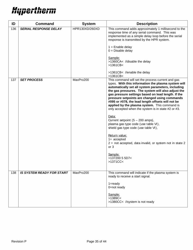
ID Command System Description 136 SERIAL RESPONSE DELAY HPR130XD/260XD This command adds approximately 1 millisecond to the
response time of any serial command. This was implemented as a simple delay loop before the serial response is transmitted by the HPR system. 1 = Enable delay 0 = Disable delay Sample: >1360CA< //disable the delay >1361CB< >1361CB< //enable the delay >1361CB<
137 SET PROCESS MaxPro200 This command will set the process current and gas types. With this information the plasma system will automatically set all system parameters, including the gas pressures. The system will also adjust the gas pressure settings based on lead length. If the pressure setpoints are changed using commands #095 or #078, the lead length offsets will not be applied by the plasma system. This command is only accepted when the system is in state #2 or #3. Data: Current setpoint (5 – 200 amps), plasma gas type code (use table VI), shield gas type code (use table VI),
Return value: 1= accepted 2 = not accepted, data invalid, or system not in state 2 or 3 Sample: >137200 5 5D7< >1371CC<
138 IS SYSTEM READY FOR START MaxPro200 This command will indicate if the plasma system is ready to receive a start signal. 1=ready 0=not ready Sample: >1389C< >1380CC< //system is not ready
Revision P Page 36 of 44
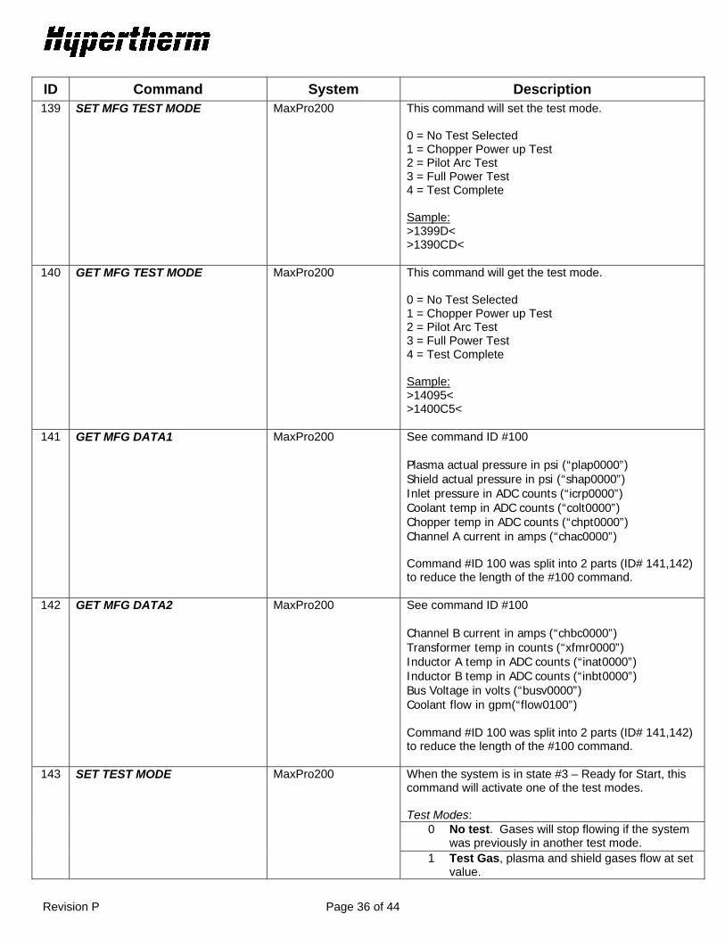
ID Command System Description 139 SET MFG TEST MODE MaxPro200 This command will set the test mode.
0 = No Test Selected 1 = Chopper Power up Test 2 = Pilot Arc Test 3 = Full Power Test 4 = Test Complete Sample: >1399D< >1390CD<
140 GET MFG TEST MODE MaxPro200 This command will get the test mode. 0 = No Test Selected 1 = Chopper Power up Test 2 = Pilot Arc Test 3 = Full Power Test 4 = Test Complete Sample: >14095< >1400C5<
141 GET MFG DATA1 MaxPro200 See command ID #100 Plasma actual pressure in psi (“plap0000”) Shield actual pressure in psi (“shap0000”) Inlet pressure in ADC counts (“icrp0000”) Coolant temp in ADC counts (“colt0000”) Chopper temp in ADC counts (“chpt0000”) Channel A current in amps (“chac0000”) Command #ID 100 was split into 2 parts (ID# 141,142) to reduce the length of the #100 command.
142 GET MFG DATA2 MaxPro200 See command ID #100 Channel B current in amps (“chbc0000”) Transformer temp in counts (“xfmr0000”) Inductor A temp in ADC counts (“inat0000”) Inductor B temp in ADC counts (“inbt0000”) Bus Voltage in volts (“busv0000”) Coolant flow in gpm(“flow0100”) Command #ID 100 was split into 2 parts (ID# 141,142) to reduce the length of the #100 command.
143 SET TEST MODE MaxPro200 When the system is in state #3 – Ready for Start, this command will activate one of the test modes. Test Modes:
0 No test. Gases will stop flowing if the system was previously in another test mode.
1 Test Gas, plasma and shield gases flow at set value.
Revision P Page 37 of 44
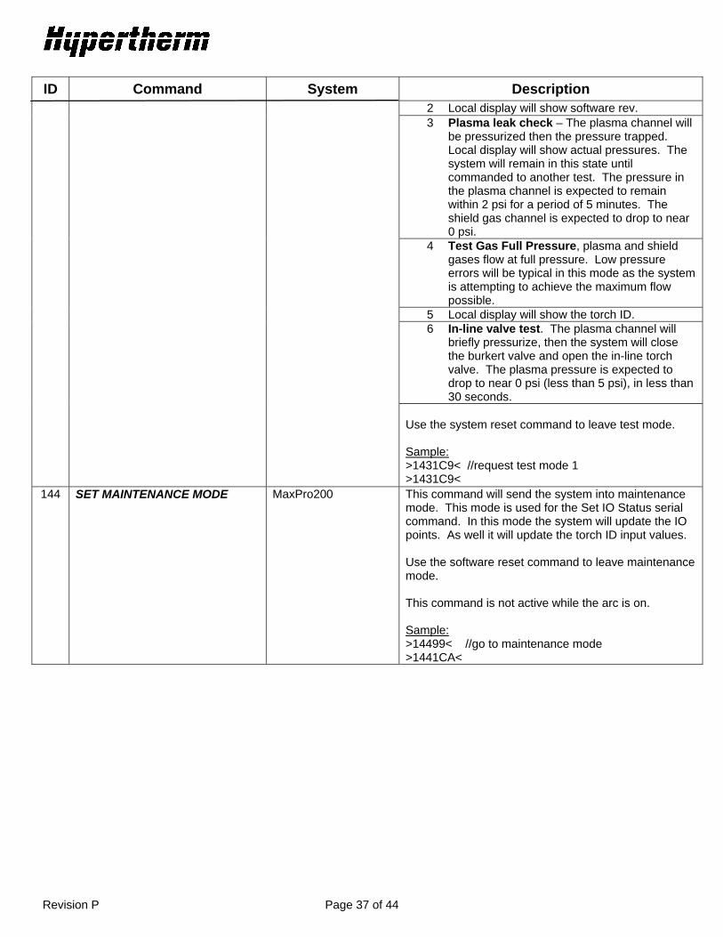
ID Command System Description 2 Local display will show software rev. 3 Plasma leak check – The plasma channel will
be pressurized then the pressure trapped. Local display will show actual pressures. The system will remain in this state until commanded to another test. The pressure in the plasma channel is expected to remain within 2 psi for a period of 5 minutes. The shield gas channel is expected to drop to near 0 psi.
4 Test Gas Full Pressure, plasma and shield gases flow at full pressure. Low pressure errors will be typical in this mode as the system is attempting to achieve the maximum flow possible.
5 Local display will show the torch ID. 6 In-line valve test. The plasma channel will
briefly pressurize, then the system will close the burkert valve and open the in-line torch valve. The plasma pressure is expected to drop to near 0 psi (less than 5 psi), in less than 30 seconds.
Use the system reset command to leave test mode. Sample: >1431C9< //request test mode 1 >1431C9<
144 SET MAINTENANCE MODE MaxPro200 This command will send the system into maintenance mode. This mode is used for the Set IO Status serial command. In this mode the system will update the IO points. As well it will update the torch ID input values. Use the software reset command to leave maintenance mode. This command is not active while the arc is on. Sample: >14499< //go to maintenance mode >1441CA<

Revision P Page 38 of 44
ID Command System Description 145 READ TORCH ID MaxPro200 This command will return the torch ID.
0 = No jumper detected 1 = 100 Ft mechanized torch 2 = 25 Ft mechanized torch 3 = 75 Ft mechanized torch 4 = 100 Ft hand torch 5 = reserved 6 = 50 Ft mechanized torch 7 = reserved 8 = 25 Ft hand torch 9 = 50 Ft hand torch 10 = reserved 11 = reserved 12 = 75 Ft hand torch Sample: >1459A< >14500025C< //id = 2
146 FRONT PANEL LED TEST MaxPro200 When the system is in Maintenance mode, the system will turn on or off all the LEDs on the front panel display. 1 = LEDs on 0 = LEDs off Sample: >1461CC< //turn on all LEDs >1461CC<
147 SET REDCART MODE MaxPro200 This command is similar to maintenance mode (id #144) except the user interface is still enabled. . Sample: >1479C< >1471CD<
d. Error Responses If there is a problem with the serial command the module will return an error. Bad Checksum
Return ID: 500 Description: The serial command received does not have the correct checksum. Sample: >00091< - checksum should be 90 not 91 >50095< - bad checksum

Revision P Page 39 of 44
Bad Command Return ID: 501 Description: If the module does not recognize the command ID it will return ID 501. Sample >999AB< - unknown ID >50196< - bad command
e. Calculating Checksums Checksum is calculated on the command ID and command data only.
HELLO Command: >00090< 0 = 0x30 (ASCII value for number 0) 0 = 0x30 0 = 0x30 ----------- checksum = 0x30 + 0x30 + 0x30 = 90 READ INPUTS power supply response: >107000058< 1 = 0x31 0 = 0x30 7 = 0x37 0 = 0x30 0 = 0x30 0 = 0x30 0 = 0x30 ----------- checksum = 0x31 + 0x30 + 0x37 + 0x30 + 0x30 + 0x30 + 0x30 = 0x158 We only use the 2 least significant digits so the checksum = 58
IV) Error Codes ID Name Description
000 NO ERROR System is ready to run
009 FLOW SWITCH TEST When the pump is restarted after a pump timeout (30 minutes without a start signal) the system will test the flow switch to make sure there is sufficient flow before firing the torch.

Revision P Page 40 of 44
012 TEST IN PROGRESS One in the gas test modes is running
013 TEST PASSED The test completed successfully
014 CUT GAS CHANNEL #1 FAIL The gas pressure is dropping on channel #1, indicating a leak
015 CUT GAS CHANNEL #2 FAIL The gas pressure is dropping on channel #2, indicating a leak
016 PLASMA RAMPDOWN FAIL Plasma pressure did not decrease in the allotted time
017 SHIELD RAMPDOWN FAIL Shield pressure did not decrease in the allotted time
018 PUMP OVER PRESSURE Pump output has exceeded 200 psi
020 NO PILOT ARC No current detected from choppers before 1-second timeout
021 NO ARC TRANSFER No transfer signal detected before 300-msec timeout
024 LOST CURRENT CH1 After transfer lost chopper current signal
025 LOST CURRENT CH2 After transfer lost chopper current signal
026 LOST TRANSFER After transfer lost the transfer signal
027 LOST PHASE When main contactor is engaged no phase ok input
028 LOST CURRENT CH3 After transfer lost chopper current signal
030 GAS SYSTEM ERROR A failure had a occurred in the gas system
031 START LOST Start signal was removed before steady state operation
032 HOLD TIMEOUT Hold signal was applied for longer than 60 seconds
033 PRE CHARGE TIMEOUT Gas console was not able to charge the gas lines to the correct value
034 LOST CURRENT CH4 After transfer lost chopper current signal
042 N2 PURGE LOW PRESSURE ERROR Low N2 gas pressure while purging because of switching from a fuel gas process to an oxidizing process or vice versa
044 LOW PLASMA GAS PRESSURE Gas pressure under lower limit (15 psi preflow, 50 psi cutflow)
045 HIGH PLASMA GAS PRESSURE Gas pressure over upper limit (110 psi)
046 LOW LINE VOLTAGE Line voltage is under lower limit (-15%)
047 HIGH LINE VOLTAGE Line voltage is over upper limit (+15%)
048 CAN ERROR An error occurred with the CAN communication system
050 START ON AT INIT Start signal input is active during power up
053 LOW SHIELD GAS PRESSURE Gas pressure is under lower limit (2 psi)
054 HIGH SHIELD GAS PRESSURE Gas pressure is over upper limit (110 psi)
055 MV 1 INLET PRESSURE Motor valve 1 inlet pressure is less than 90 psi or greater than 130 psi.
056 MV 2 INLET PRESSURE Motor valve 2 inlet pressure is less than 90 psi or greater than 130 psi.
057 CUT GAS 1 PRESSURE In the selection console, cut gas 1 outlet pressure is less than 90 psi or greater than 130 psi.

Revision P Page 41 of 44
058 CUT GAS 2 PRESSURE In the selection console, if cut gas 2 outlet pressure is less than 90 psi for non mixing or less than 20 psi when mixing or greater than 130 psi.
060 LOW COOLANT FLOW Coolant flow is present but is less than the required 0.6 gpm
061 NO PLASMA GAS TYPE Plasma gas has not been selected
062 NO SHIELD GAS TYPE Shield gas has not been selected or system is in test mode
065 CHOPPER1 OVERTEMP Chopper #1 overheated
066 CHOPPER2 OVERTEMP Chopper #2 overheated
067 MAGNETICS OVERTEMP Transformer has overheated
071 COOLANT OVERTEMP Torch coolant has overheated
072 AUTOMATIC GAS CONTROL BOARD
OVERTEMP Control board has exceeded 90 degrees C
073 CHOPPER3 OVERTEMP Chopper #3 overheated
074 CHOPPER4 OVERTEMP Chopper #4 overheated
075 LEM 3 CURRENT LOW Current is less than 10 amps during the chopper test
076 LEM 4 CURRENT LOW Current is less than 10 amps during the chopper test
093 NO COOLANT FLOW Coolant flow is less than 0.6 gpm or greater than 3.0 gpm
095 LEM 4 CURRENT HIGH Current has exceeded 35 amps during chopper test
099 CHOPPER1 OVERTEMP AT INIT Chopper #1 is indicating overtemp during powerup
100 CHOPPER2 OVERTEMP AT INIT Chopper #2 is indicating overtemp during power up
101 MAGNETICS OVERTEMP AT INIT Transformer is indicating overtemp during powerup
102 LEM SENSOR A FAULT Chopper A current signal is invalid
103 LEM 1 CURRENT HIGH Current has exceeded 35 amps during chopper test
104 LEM 2 CURRENT HIGH Current has exceeded 35 amps during chopper test
105 LEM 1 CURRENT LOW Current is less than 10 amps during the chopper test
106 LEM 2 CURRENT LOW Current is less than 10 amps during the chopper test
107 LEM 3 CURRENT HIGH Current has exceeded 35 amps during chopper test
108 TRANSFER AT INIT The system has detected current on the work lead during power up
109 COOLANT FLOW AT INIT Coolant flow is greater than 0.3 gpm when pump is off.
111 COOLANT OVERTEMP AT INIT Coolant is indicating overtemp during powerup
116 WATCHDOG INTERLOCK CAN communication error
123 MV 1 ERROR Motor valve 1 did not move into position within 60 seconds
124 MV 2 ERROR Motor valve 2 did not move into position within 60 seconds
133 UNKNOWN GAS CONSOLE TYPE The power supply control board does not recognize the gas console installed or has not received a CAN message identifying the type of console installed
134 CHOPPER 1 OVERCURRENT Chopper 1 current feedback has exceeded 160 amps
138 CHOPPER 2 OVERCURRENT Chopper 2 current feedback has exceeded 160 amps
Revision P Page 42 of 44
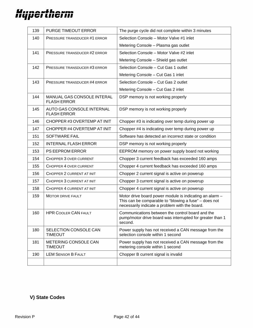
139 PURGE TIMEOUT ERROR The purge cycle did not complete within 3 minutes
140 PRESSURE TRANSDUCER #1 ERROR Selection Console – Motor Valve #1 inlet
Metering Console – Plasma gas outlet
141 PRESSURE TRANSDUCER #2 ERROR Selection Console – Motor Valve #2 inlet
Metering Console – Shield gas outlet
142 PRESSURE TRANSDUCER #3 ERROR Selection Console – Cut Gas 1 outlet
Metering Console – Cut Gas 1 inlet
143 PRESSURE TRANSDUCER #4 ERROR Selection Console – Cut Gas 2 outlet
Metering Console – Cut Gas 2 inlet
144 MANUAL GAS CONSOLE INTERAL
FLASH ERROR DSP memory is not working properly
145 AUTO GAS CONSOLE INTERNAL
FLASH ERROR DSP memory is not working properly
146 CHOPPER #3 OVERTEMP AT INIT Chopper #3 is indicating over temp during power up
147 CHOPPER #4 OVERTEMP AT INIT Chopper #4 is indicating over temp during power up
151 SOFTWARE FAIL Software has detected an incorrect state or condition
152 INTERNAL FLASH ERROR DSP memory is not working properly
153 PS EEPROM ERROR EEPROM memory on power supply board not working
154 CHOPPER 3 OVER CURRENT Chopper 3 current feedback has exceeded 160 amps
155 CHOPPER 4 OVER CURRENT Chopper 4 current feedback has exceeded 160 amps
156 CHOPPER 2 CURRENT AT INIT Chopper 2 current signal is active on powerup
157 CHOPPER 3 CURRENT AT INIT Chopper 3 current signal is active on powerup
158 CHOPPER 4 CURRENT AT INIT Chopper 4 current signal is active on powerup
159 MOTOR DRIVE FAULT Motor drive board power module is indicating an alarm – This can be comparable to “blowing a fuse” – does not necessarily indicate a problem with the board.
160 HPR COOLER CAN FAULT Communications between the control board and the pump/motor drive board was interrupted for greater than 1 second.
180 SELECTION CONSOLE CAN
TIMEOUT Power supply has not received a CAN message from the selection console within 1 second
181 METERING CONSOLE CAN
TIMEOUT Power supply has not received a CAN message from the metering console within 1 second
190 LEM SENSOR B FAULT Chopper B current signal is invalid
V) State Codes

Revision P Page 43 of 44
ID MaxPro State HPR State 00 POWER UP IDLE
01 INITIAL CHECKS N/A
02 GAS PURGE PURGE
03 READY FOR START IDLE2
04 PREFLOW PREFLOW
05 PREFLOW HOLD PILOT ARC
06 IGNITE TRANSFER
07 PILOT ARC RAMPUP
08 RAMPUP STEADY STATE
09 MAIN ARC RAMPDOWN
10 RAMPDOWN FINAL RAMPDOWN
11 RAMPDOWN COMPLETE AUTO OFF
12 END OF CYCLE TEST CUTFLOW
13 --------------------- ---------------------
14 SHUTDOWN SHUTDOWN
15 RESET RESET
16 MAINTENANCE MAINTENANCE
17 STANBY ---------------------
20 TEST PREFLOW
22 --------------------- MANUAL PUMP CONTROL
23 --------------------- INLET LEAK CHECK
24 --------------------- SYSTEM LEAK CHECK
25 --------------------- BURKERT FLOW CHECK
VI) Gas Type Codes ID Gas Type Notes 0 No Gas Invalid gas type 1 Oxygen 2 Methane (CH4) 3 H35 (Argon – Hydrogen) Use H35 as plasma gas and N2 as shield gas for H35/N2
mixed plasma gas processes 4 H5 5 Air 6 Nitrogen 7 Argon 8 N95 9 N2 Channel 1 Internal N2 marking mode, not used by CNC 10 N2 Channel 2 Internal N2 marking mode, not used by CNC 11 F5 12 Ar-Air Internal Ar marking mode, not used by CNC

Revision P Page 44 of 44
VII) Serial Interface Guidelines 1. Checksum
The protocol used for the serial interface between the Hypertherm system and the CNC contains a checksum on the message being sent. The checksum should be validated for all messages to ensure the information is not corrupted.
2. Message Retries We recommend retrying a message if the original message was not acknowledged by the system. This is especially important when the high frequency ignition is active. The high frequency ignition can be active for up to 1 second and can corrupt serial communications. It is important to space the retries so that the system can handle an interruption in serial communications for up to 1 second. Another alternative to handling the high frequency ignition is to poll for the power supply state, using the GET_STATE command. If the state is (5 – Pilot arc) then stop serial communications until the state is no longer (5 – Pilot arc).
3. Cable Shielding We have chosen to use metal shell DB style machine/serial interface cables on some on the newer systems. One of the reasons this type of cable was selected is for their EMI shielding capabilities. It is important that integrity of the shielding of this cable is maintained. The shielding provides protection from the high frequency ignition system, if the cable shields are not properly terminated then the protection is not as effective. This is best achieved by ensuring the shield has a 360° termination provided on both end of the cables. Using a drain wire will not achieve the proper shielding. The cable should also be as short as possible with no coils.
4. Serial response timing
For standard HPR systems, the response to a serial command will come between 1 – 7 milliseconds after the command is received. For HPR XD systems the response time is generally reduced by 50%. For systems that require a minimum response time, serial command #136 will add 1.0 – 1.8 milliseconds to the response time of the system.
VIII) Application Notes 1. Transmitting extra characters at the end of a message or transmitting while the plasma system is
responding
The original control board 041808 and power supply control software revision H and prior can sometimes “lock up” when the power supply is receiving characters while it is transmitting. The reason for this is that the control system cannot process interrupts fast enough. In some cases, when a receive interrupt and a transmit interrupt occur very close together the system will miss one of the interrupts and will not process any more serial characters. Under normal conditions this will not be an issue. As long as you wait for a response to every command before transmitting the next command the problem will not occur. Also it is important not to include extra characters at the end of a command such as a carriage return or line feed. These are not required and can cause problems. Power supply control software revision J improves the capability of the system and will reduce the likelihood of occurrence, however it can still happen. The new style control board 041909 has fixed the problem in hardware.