Embed Size (px)
Citation preview
Nanoscale
PAPER
Cite this: Nanoscale, 2017, 9, 9034
Received 10th February 2017,Accepted 13th June 2017
DOI: 10.1039/c7nr00980a
rsc.li/nanoscale
Hyperbolic metamaterials for dispersion-assisteddirectional light emission
Lorenzo Ferrari, a Joseph Stephen Thomas Smalley, b Yeshaiahu Fainmanb andZhaowei Liu *a,b,c
A novel method is presented to outcouple high spatial frequency (large-k) waves from hyperbolic meta-
materials (HMMs) without the use of a grating. This approach relies exclusively on dispersion engineering,
and enables preferential power extraction from the top or from the side of a HMM. Multilayer (ML) HMMs
are shown to be better suited for lateral outcoupling, while nanowire HMMs are the most convenient
choice for top outcoupling. A 6-fold increase in laterally extracted power is predicted for a dipole–HMM
system with a Ag/Si ML operating at λ = 530 nm, when metallic filling ratio is changed from an unopti-
mized to the optimized one. This new design concept supports the cost-effective mass production of
high-speed HMM optical transmitters.
1 Introduction
Hyperbolic metamaterials (HMMs) are a class of optical meta-materials characterized by a uniaxial effective permittivitytensor, with components parallel and perpendicular to theoptical axis that exhibit opposite signs.1–6 They are fabricatedpredominantly in two configurations, as either a multilayerstack (ML) or a nanowire array (NW). The first consists of alter-nating metallic and dielectric (or semiconducting) layers ofdeep sub-wavelength thickness, while in the second metallicrods of deep sub-wavelength diameter and high aspect ratioare embedded into a dielectric matrix. The value of theeffective permittivity components depends on the constituentpermittivities and the metal filling ratio, ρ, which is the volu-metric percentage of metal in a unit cell of the ML or the NW.The optical anisotropy of HMMs translates into hyperbolic dis-persion, capable of supporting propagating waves with verylarge wavevectors (or k-vectors): a unique feature that enablesseveral applications, including high-resolution imaging andlithography,7–11 broadband absorption engineering,12,13
thermal control at the nanoscale,14 enhanced nonlinear pro-cesses15,16 and spontaneous emission engineering17–26
The latter in particular is technologically relevant to thefield of high-speed optical communications. As pointed out ina recent work,27 incoherent light sources with a spontaneous
emission rate enhanced via plasmonic28–30 or hyperbolic nano-structures can achieve modulation speeds comparable to orlarger than those of coherent sources, at a lower manufactur-ing and operational cost. The radiative spontaneous decay rateof a quantum emitter (molecule, electron–hole pair inquantum wells (QWs) or quantum dots (QDs)) γr = 1/τr, whereτr represents the radiative spontaneous emission lifetime,31
defines the upper bound to the 3dB electrical modulationbandwidth, f3dB, of a light-emitting diode (LED), according tothe formula f3dB = (2πτr)−1 = (2π)−1γr.32 When such a quantumlight source is brought within the near field of a HMM, thewaves with large k-vectors contained in its emission spectrumcouple to the hyperbolic medium – which supports theirpropagation – instead of decaying evanescently in the sur-rounding environment (usually air). The local photonicdensity of states (PDOS) accessible to the emitter is thereforemuch larger in HMMs than in conventional media. Fermi’sGolden Rule states that the enhancement in PDOS, quantifiedby the Purcell Factor (PF), is proportional to the enhancementin radiative spontaneous decay rate:6 because γr is proportionalto f3dB as shown above, we conclude that the emitter–HMMcoupling enhances the electrical modulation bandwidth. Thecontextual increase in the data transmission rate of the emitter(proportional to f3dB according to the Shannon SamplingTheorem32) opens up a host of opportunities in high-speedwireless (Light-Fidelity (Li-Fi),33 underwater34) and fiber-optic35 communication.
Despite this high potential, two major challenges hinderthe practical usage of fast optical transmitters based on HMMtechnology. Firstly, the discontinuous decrease in PDOS fromHMMs to their surrounding environment implies that theirinterface with air suffers a remarkable impedance mismatch.
aMaterials Science and Engineering, University of California, San Diego,
9500 Gilman Drive, La Jolla, CA 92093-0418, USA. E-mail: [email protected] of Electrical and Computer Engineering, University of California,
San Diego, 9500 Gilman Drive, La Jolla, CA 92093-0407, USAcCenter for Memory and Recording Research, University of California, San Diego,
9500 Gilman Drive, La Jolla, CA 92093-0401, USA
9034 | Nanoscale, 2017, 9, 9034–9048 This journal is © The Royal Society of Chemistry 2017
Publ
ishe
d on
14
June
201
7. D
ownl
oade
d by
Uni
vers
ity o
f C
alif
orni
a -
San
Die
go o
n 04
/10/
2017
02:
06:5
9.
View Article OnlineView Journal | View Issue
As a consequence, large-k waves remain trapped inside hyper-bolic media, unless a suitable mechanism is provided thatmediates the HMM-to-air transition. The traditional solutiondescribed in the literature consists of milling through ordepositing on top of the HMM a sub-wavelength grating,whose periodicity provides the matching k-vector required bymomentum conservation.22,23,36–39 Secondly, it is not trivial toshape the far-field emission pattern of the light outcoupledfrom HMMs. Directional control of emission is beneficial forapplications such as on-chip photonics, where light must beswitched in-plane and out-of-plane with respect to the chipsurface, and fiber-optic communication, where the opticalsignal must be effectively channeled into the numerical aper-ture of a multi-mode or single-mode fiber. To date, the onlyoutcoupling structure shown to control the emission pattern isa bullseye grating.36,38
The existing approaches to address such challenges areinadequate from a manufacturing standpoint. Adding a sub-wavelength grating typically means extra time and cost in fabri-cation: gratings are defined via focused ion-beam (FIB)22 orelectron-beam lithography,37,38 which are not economicallysustainable for mass production because of their limitedthroughput. Furthermore, the optimum grating geometrydetermined via analytical or numerical simulations is oftenhardly achievable in practice with the above-mentioned tech-niques. 1D gratings with rectangular cross-section have notshown good directional control properties;22 bullseye gratingsextract radiation into a conical pattern,38 but it is not clearlyunderstood how to control and shape the emission patternarbitrarily via design parameters. A common issue to allgrating types is that the extraction efficiency and the direc-tional control depend on the relative emitter-grating position:a quantum light source contained in a horizontal plane belowthe grating displays a different behavior whether it is locatedadjacent to a crest or to a trough.22 As a consequence, the out-coupling performance of the grating is not univocally deter-mined, but results from an average over the spatial distri-bution of the emitters.
In this paper, we propose a novel paradigm based on dis-persion engineering to outcouple large-k waves from HMMs.With a suitable selection of the HMM filling ratio, we extracthigh k-vectors into the far field by compressing their com-ponent parallel or perpendicular to the HMM optical axis,thereby enhancing the overall power routed along the corres-ponding Cartesian direction (see Fig. 1). This method was pre-viously suggested by West et al.40 for the case of a ML HMM ofType II; the present work extends the tractation, to includeboth Type I and Type II dispersion and both ML and NW geo-metries. By lifting the requirement for a grating, our approachmakes the fabrication of fast optical transmitters based onquantum emitter–HMM coupling more practical and versatile.The extraction mechanism relies on the bulk properties of theHMM, rather than on spatially varying features of a superi-mposed structure: as such, it affects equally all the emitterscontained in the same plane parallel or orthogonal to theoptical axis. This enables the effective channeling of emission
from a QW, which for practical purposes can be thought of asa plane of quantum sources (electron–hole pairs). We firstdiscuss the theory of dispersion-assisted directional out-coupling in the ideal case of zero optical losses, analyzing thefour HMM configurations that induce this phenomenon. Wethen assess two metal/dielectric material systems for MLHMMs in the visible range, and observe how their lossrestricts the practically achievable configurations and theband of outcoupled k-vectors. The developed model is finallyapplied to the study of a colloidal QD–HMM system: bymeans of finite element electromagnetic simulations, wedetermine how the light emitted from a point dipole (repre-senting the QD) into a block of HMM is outcoupled by thelatter into directional far-field radiation, polarized along theoptical axis independently of the dipole orientation. Afterevaluating the performance of the QD–HMM system, we con-clude our study by suggesting guidelines for its practicalimplementation and future development.
2 Results and discussion2.1 Principle of large-k waves outcoupling via dispersionengineering
In the following we explain how large-k waves can be direction-ally extracted from lossless HMMs via a filling ratio optimiz-ation procedure. The results presented hold true for anymedium with hyperbolic dispersion regardless of how itseffective parameters are retrieved, and therefore indistinctlyapply to ML and to NW configurations. Since ML HMMs offera wider constituent materials choice and are more versatilefrom a fabrication standpoint, we will focus on this category inthe subsequent analysis.
Fig. 1 Artistic representation of high-speed optical transmission viaunpatterned HMMs. Light emitted from a multiple quantum well,depicted by 3 green (left) and red (right) luminescent layers, couples to aML (left) and a NW (right) HMM block. The hyperbolic dispersions aredesigned to extract radiation respectively from the side or from the topinterface.
Nanoscale Paper
This journal is © The Royal Society of Chemistry 2017 Nanoscale, 2017, 9, 9034–9048 | 9035
Publ
ishe
d on
14
June
201
7. D
ownl
oade
d by
Uni
vers
ity o
f C
alif
orni
a -
San
Die
go o
n 04
/10/
2017
02:
06:5
9.
View Article Online
A hyperbolic medium is described by a uniaxial permittivitytensor of the form:6
ε ¼ε? 0 00 ε? 00 0 εzz
24
35; ð1Þ
in a Cartesian frame of reference {x,y,z} where the unit vector zis parallel to the optical axis. For a periodic ML HMM withlayer interfaces orthogonal to z, the effective parameters ε⊥and εzz are obtained through the homogenization formulae:6
ε?ðω; ρÞ ¼ ρεmðωÞ þ ð1� ρÞεdðωÞ; ð2Þ
εzzðω; ρÞ ¼ ρ
εmðωÞ þ1� ρ
εdðωÞ� ��1
: ð3Þ
εm(ω) and εd(ω) are respectively the permittivities of the met-allic and the dielectric layers, which in the absence of spatialdispersion and optical loss depend solely on the angular fre-quency ω and are real quantities, and 0 < ρ < 1 is the volu-metric filling ratio of metal. The dispersion of the effectivemedium is hyperbolic only at those frequencies and at thosefilling ratios at which ε⊥εzz < 0. This requirement classifies thebehavior of HMMs into two distinct types:
Type I. When ε⊥(ω,ρ) > 0 and εzz(ω,ρ) < 0;Type II. When ε⊥(ω,ρ) < 0 and εzz(ω,ρ) > 0.Let us consider the interface, contained in the xy plane of
the real space, between a nonmagnetic HMM in the z < 0region and a lossless isotropic dielectric medium in the z > 0region. A plane wave with wavevector kHMM of arbitrary magni-
tude is subject inside the hyperbolic medium to thedispersion:
kHMM;?k0
� �2 1εzz
þ kHMM;z
k0
� �2 1ε?
¼ 1; ð4Þ
where, by virtue of the cylindrical symmetry of the permittivity,we introduced the cylindrical coordinatekHMM;? ¼ ffiffiffiffiffiffiffiffiffiffiffiffiffiffiffiffiffiffiffiffiffiffiffiffiffiffiffiffiffiffiffiffiffiffiffiffiffiffi
kHMM;x2 þ kHMM;y
2p
, and k0 = ω/c (c = speed of lightin vacuum). In the dielectric medium, dispersion takes insteadthe form
kdiel;?k0
� �2
þ kdiel;zk0
� �2
¼ n2; ð5Þ
where kdiel;? ¼ ffiffiffiffiffiffiffiffiffiffiffiffiffiffiffiffiffiffiffiffiffiffiffiffiffiffiffiffiffiffiffikdiel;x2 þ kdiel;y2
pand n is the refractive index,
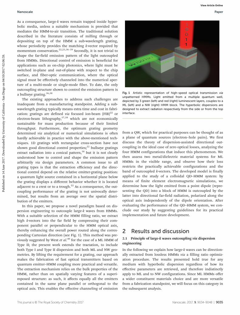
and the magnitude of the wavevector kdiel is equal to k0n.Eqn (4) and (5) define respectively a hyperboloid and a spherein the space of k-vectors at a given frequency ω. Their cross-section in the kxkz plane is represented in Fig. 2(a) for the caseof a Type II HMM and air. To simplify the notation and makethe discussion clearer, we restrict the following analysis to the(kx > 0, kz > 0) quadrant; analogous considerations can beextended by symmetry to the remaining 3 quadrants. Wedefine “large-k waves” those plane waves with k-vector |kHMM|> |kair|, and “short-k waves” those with k-vector |kHMM| ≤ |kair|.The HMM supports the propagation of large-k waves of com-ponents kHMM,x > k0nair = k0 and kHMM;z >�< k0. When such wavesreach the HMM–air boundary, the conservation of the k-vectorcomponent parallel to the interface mandates that kair,x =kHMM,x. Since kHMM,x > k0, kair;z ¼
ffiffiffiffiffiffiffiffiffiffiffiffiffiffiffiffiffiffiffiffiffiffiffiffiffiffiffiffik02 � kHMM;x
2p
is a purely
Fig. 2 Iso-frequency curve of Type II HMM (blue hyperbola) showing large k-vector outcoupling upwards into air (red circle) via (a) grating and (b)dispersion engineering. The two configurations are schematically represented above the plots (Λ = grating pitch). For clarity, only the right branch ofthe HMM iso-frequency curve is shown, and the normalization by k0 is omitted in the vector nomenclature. In (b), the portion of outcoupledk-vector band falling within the (kx > 0, kz > 0) quadrant is highlighted in light blue (short-k waves) and pink (large-k waves).
Paper Nanoscale
9036 | Nanoscale, 2017, 9, 9034–9048 This journal is © The Royal Society of Chemistry 2017
Publ
ishe
d on
14
June
201
7. D
ownl
oade
d by
Uni
vers
ity o
f C
alif
orni
a -
San
Die
go o
n 04
/10/
2017
02:
06:5
9.
View Article Online
imaginary number. This turns a propagating wave in the HMMinto an evanescent wave in air, preventing its successful out-coupling into the far-field.
Impedance mismatch is traditionally bridged by patterninga grating onto the HMM (inset of Fig. 2(a)). A 1D grating withpitch Λ and periodicity along x provides an extra k-vector kΛ =kΛx = (2π/Λ)x,41 outcoupling into air the band of k-vectors withcomponents kHMM,x > k0 such that kHMM,x = kΛ + kair,x is veri-fied for some real kair,x ≤ k0. At that point indeed the planewave becomes propagating in air, as eqn (5) forces its com-ponent kair,z to be a real quantity ≤k0.
The same goal can be achieved with the alternativeapproach schematized in Fig. 2(b). If the filling ratio ρ of theHMM is properly designed, the hyperbolic iso-frequency curvegets “straightened” along the z direction and “squeezed” alongthe x direction within the circular iso-frequency curve of air. Inthis case, there exists in the HMM a band of k-vectors whichpossess a conserved component kHMM,x ≤ k0, and thereforeretain their propagating nature across the HMM–air boundary.The band is delimited by two extremes kHMM,1 and kHMM,2,and contains both short- and large-k waves, separated by avector kHMM,sep (not drawn in the figure). kHMM,1, kHMM,sep andkHMM,2 are defined as the intersections of the hyperbolic iso-frequency curve respectively with the x axis, the circular iso-fre-quency curve of air and the straight line kx ≡ k0. The relativecontribution of large-k waves, (kHMM,2x − kHMM,sep x)/(kHMM,2x −kHMM,1x), increases as the hyperbolic iso-frequency curve getsmore squeezed; the z-bandwidth kHMM,2z − kHMM,sep z and thez-density dkHMM z/dkHMM x of large-k waves increase as thehyperbolic iso-frequency curve gets straighter. Refraction intoair occurs within an angular range θ1 ≤ θ ≤ θ2, where θ is theangle between the refracted k-vector and the optical axis z,θ 1 ¼ arctanðkHMM;1x=
ffiffiffiffiffiffiffiffiffiffiffiffiffiffiffiffiffiffiffiffiffiffiffiffiffiffiffiffiffiffik02 � kHMM;1x
2p Þ and θ2 = 90°. The limit
case of infinite z-bandwidth and refraction normal to the inter-face (θ1 = θ2 = 0°) is reached when the hyperbola branchesbecome straight lines and collapse onto the optical axis, asmathematically detailed in Appendix A. Although such situ-ation appears ideal for applications, before drawing con-clusions we must include energy propagation in our analysis.We recall that the power flux within a medium is perpendicu-lar to the isofrequency surfaces.6 When the two branches ofthe hyperbola become parallel to the z axis, namely the curva-ture at vertices becomes minimal, energy within the HMMflows parallel to the HMM–air interface and never reaches it,making outcoupling impossible. Therefore a tradeoff isrequired: the curvature of the hyperbola at vertices must besmall enough to allow a sufficient z-bandwidth, but largeenough to avoid that energy travels too long within the HMM –
with the risk of being dissipated by loss – before touching theboundary with air.
2.2 Design guidelines and outcoupling configurations
We now derive comprehensive guidelines to optimize large-kwave extraction from a Type II HMM into air through a flatinterface contained in the xy plane (top outcoupling). Our con-siderations are again restricted for simplicity to a cross-section
of the iso-frequency curve in the (kx > 0, kz > 0) quadrant. Asconcluded in the previous subsection, the target dispersionwill be the one that enables infinite bandwidth and normalemission; once the optimum εzz and ε⊥ are obtained, we willhave to arbitrarily (the tradeoff depends on the application)relax the infinite bandwidth condition to achieve successfuloutcoupling.
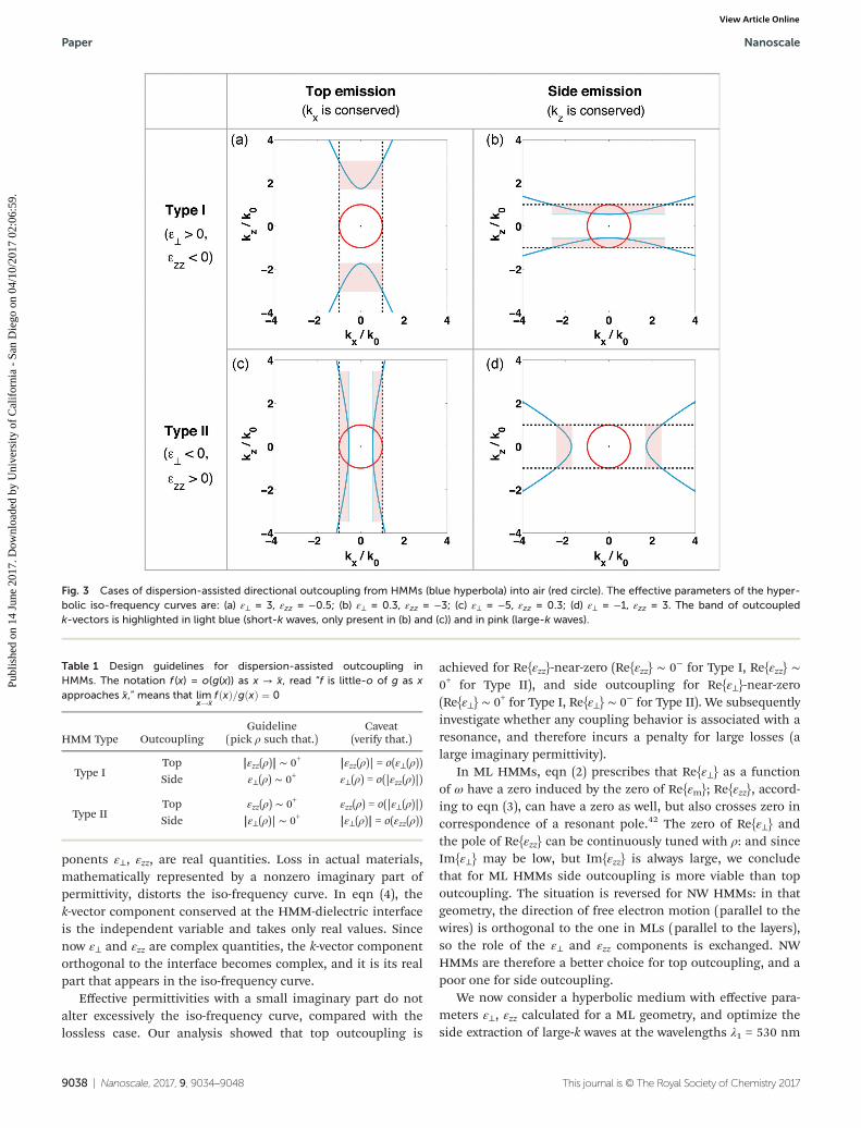
The target iso-frequency curve corresponds to a limit hyper-bolic curve with maximal straightening and maximal squeez-ing; these simultaneous requests are formalized in system (13)of Appendix A. When optimization is performed at a givenemission frequency ω, we have two equations, involving twofunctions ε⊥(ω,ρ) and εzz(ω,ρ), and only one variable ρ. Theresulting overdetermined system admits a solution ρ such thatεzz(ρ) → 0+ as ρ → ρ, provided that |ε⊥(ρ)| approaches a finitevalue or approaches 0 less quickly than εzz(ρ) does. Therefore,we optimize dispersion as follows: we choose ρ such that εzz(ρ)∼ 0+ (but not exactly εzz(ρ) = 0, to avoid the energy propagationissue discussed above), making sure that the related conditionon ε⊥(ρ) is verified. Fig. 3(c) shows an iso-frequency curvewhere εzz does not take the limit value 0, but is small enoughto possess a band of outcoupled k-vectors, highlighted in lightblue (short-k waves) and pink (large-k waves).
Large wavevectors can also be extracted when the HMM–airinterface lies in the yz plane (side outcoupling). In this case,one equation suffices to request both maximal straighteningand maximal squeezing (Appendix A). Its solution ρ satisfies|ε⊥(ρ)| → 0+ as ρ → ρ, provided that εzz(ρ) approaches a finitevalue or approaches 0 less quickly than |ε⊥(ρ)| does. Inanalogy to the previous reasoning, we do not select ρ such that|ε⊥(ρ)| = 0, but rather |ε⊥(ρ)| ∼ 0+; a situation where ε⊥ is smallenough to possess an outcoupled band, but not yet approach-ing the limit value 0, is represented in Fig. 3(d). While in thecase of top extraction the outcoupled band always containsboth short- and large-k waves, in the case of side extractiononly the latter are present if the condition εzz(ρ) > 1 is verified(like in Fig. 3(d)).
Type I dispersion is mathematically a 90° rotation of theType II one (Appendix A). With arguments and caveats similarto those hitherto discussed, top outcoupling is achieved at ρsuch that |εzz(ρ)| ∼ 0+ (an iso-frequency curve with small εzz isshown in Fig. 3(a)), while side outcoupling requires ε⊥(ρ) ∼ 0+
(an iso-frequency curve with small ε⊥ is shown in Fig. 3(b)).Both short- and large-k waves are always present in a side-out-coupled band, while a top-outcoupled one features exclusivelylarge-k components if the condition ε⊥(ρ) > 0 is verified(Fig. 3(a)).
The design guidelines traced in the present subsection,which relate large-k extraction to the epsilon-near-zero (ENZ)behavior of the effective permittivity components, are summar-ized in Table 1.
2.3 Influence of loss on dispersion
Thus far we have assumed that the constituent materials ofthe ML or the NW are lossless. This implies that their permit-tivities εm and εd, and therefore the effective permittivity com-
Nanoscale Paper
This journal is © The Royal Society of Chemistry 2017 Nanoscale, 2017, 9, 9034–9048 | 9037
Publ
ishe
d on
14
June
201
7. D
ownl
oade
d by
Uni
vers
ity o
f C
alif
orni
a -
San
Die
go o
n 04
/10/
2017
02:
06:5
9.
View Article Online
ponents ε⊥, εzz, are real quantities. Loss in actual materials,mathematically represented by a nonzero imaginary part ofpermittivity, distorts the iso-frequency curve. In eqn (4), thek-vector component conserved at the HMM-dielectric interfaceis the independent variable and takes only real values. Sincenow ε⊥ and εzz are complex quantities, the k-vector componentorthogonal to the interface becomes complex, and it is its realpart that appears in the iso-frequency curve.
Effective permittivities with a small imaginary part do notalter excessively the iso-frequency curve, compared with thelossless case. Our analysis showed that top outcoupling is
achieved for Re{εzz}-near-zero (Re{εzz} ∼ 0− for Type I, Re{εzz} ∼0+ for Type II), and side outcoupling for Re{ε⊥}-near-zero(Re{ε⊥} ∼ 0+ for Type I, Re{ε⊥} ∼ 0− for Type II). We subsequentlyinvestigate whether any coupling behavior is associated with aresonance, and therefore incurs a penalty for large losses (alarge imaginary permittivity).
In ML HMMs, eqn (2) prescribes that Re{ε⊥} as a functionof ω have a zero induced by the zero of Re{εm}; Re{εzz}, accord-ing to eqn (3), can have a zero as well, but also crosses zero incorrespondence of a resonant pole.42 The zero of Re{ε⊥} andthe pole of Re{εzz} can be continuously tuned with ρ: and sinceIm{ε⊥} may be low, but Im{εzz} is always large, we concludethat for ML HMMs side outcoupling is more viable than topoutcoupling. The situation is reversed for NW HMMs: in thatgeometry, the direction of free electron motion (parallel to thewires) is orthogonal to the one in MLs (parallel to the layers),so the role of the ε⊥ and εzz components is exchanged. NWHMMs are therefore a better choice for top outcoupling, and apoor one for side outcoupling.
We now consider a hyperbolic medium with effective para-meters ε⊥, εzz calculated for a ML geometry, and optimize theside extraction of large-k waves at the wavelengths λ1 = 530 nm
Fig. 3 Cases of dispersion-assisted directional outcoupling from HMMs (blue hyperbola) into air (red circle). The effective parameters of the hyper-bolic iso-frequency curves are: (a) ε⊥ = 3, εzz = −0.5; (b) ε⊥ = 0.3, εzz = −3; (c) ε⊥ = −5, εzz = 0.3; (d) ε⊥ = −1, εzz = 3. The band of outcoupledk-vectors is highlighted in light blue (short-k waves, only present in (b) and (c)) and in pink (large-k waves).
Table 1 Design guidelines for dispersion-assisted outcoupling inHMMs. The notation f (x) = o(g(x)) as x → x, read “f is little-o of g as xapproaches x,” means that lim
x!�xfðxÞ=gðxÞ ¼ 0
HMM Type OutcouplingGuideline
(pick ρ such that.)Caveat
(verify that.)
Type ITop |εzz(ρ)| ∼ 0+ |εzz(ρ)| = o(ε⊥(ρ))Side ε⊥(ρ) ∼ 0+ ε⊥(ρ) = o(|εzz(ρ)|)
Type IITop εzz(ρ) ∼ 0+ εzz(ρ) = o(|ε⊥(ρ)|)Side |ε⊥(ρ)| ∼ 0+ |ε⊥(ρ)| = o(εzz(ρ))
Paper Nanoscale
9038 | Nanoscale, 2017, 9, 9034–9048 This journal is © The Royal Society of Chemistry 2017
Publ
ishe
d on
14
June
201
7. D
ownl
oade
d by
Uni
vers
ity o
f C
alif
orni
a -
San
Die
go o
n 04
/10/
2017
02:
06:5
9.
View Article Online
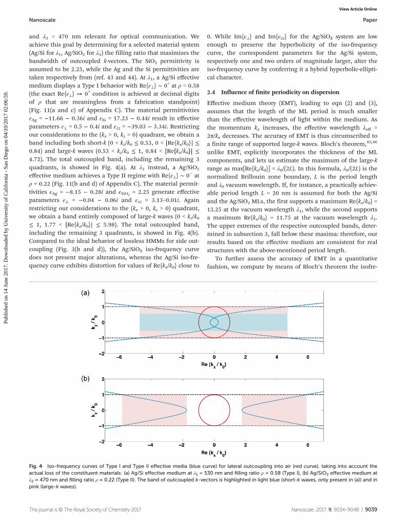
and λ2 = 470 nm relevant for optical communication. Weachieve this goal by determining for a selected material system(Ag/Si for λ1, Ag/SiO2 for λ2) the filling ratio that maximizes thebandwidth of outcoupled k-vectors. The SiO2 permittivity isassumed to be 2.25, while the Ag and the Si permittivities aretaken respectively from (ref. 43 and 44). At λ1, a Ag/Si effectivemedium displays a Type I behavior with Re{ε⊥} ∼ 0+ at ρ = 0.58(the exact Re{ε⊥} → 0+ condition is achieved at decimal digitsof ρ that are meaningless from a fabrication standpoint)(Fig. 11(a and c) of Appendix C). The material permittivitiesεAg = −11.66 − 0.36i and εSi = 17.23 − 0.44i result in effectiveparameters ε⊥ = 0.5 − 0.4i and εzz = −39.03 − 3.34i. Restrictingour considerations to the (kx > 0, kz > 0) quadrant, we obtain aband including both short-k (0 < kz/k0 ≤ 0.53, 0 < |Re{kx/k0}| ≤0.84) and large-k waves (0.53 < kz/k0 ≤ 1, 0.84 < |Re{kx/k0}| ≤4.72). The total outcoupled band, including the remaining 3quadrants, is showed in Fig. 4(a). At λ2 instead, a Ag/SiO2
effective medium achieves a Type II regime with Re{ε⊥} ∼ 0− atρ = 0.22 (Fig. 11(b and d) of Appendix C). The material permit-tivities εAg = −8.15 − 0.28i and εSiO2
= 2.25 generate effectiveparameters ε⊥ = −0.04 − 0.06i and εzz = 3.13–0.01i. Againrestricting our considerations to the (kx > 0, kz > 0) quadrant,we obtain a band entirely composed of large-k waves (0 < kz/k0≤ 1, 1.77 < |Re{kx/k0}| ≤ 5.98). The total outcoupled band,including the remaining 3 quadrants, is showed in Fig. 4(b).Compared to the ideal behavior of lossless HMMs for side out-coupling (Fig. 3(b and d)), the Ag/SiO2 iso-frequency curvedoes not present major alterations, whereas the Ag/Si iso-fre-quency curve exhibits distortion for values of Re{kx/k0} close to
0. While Im{ε⊥} and Im{εzz} for the Ag/SiO2 system are lowenough to preserve the hyperbolicity of the iso-frequencycurve, the correspondent parameters for the Ag/Si system,respectively one and two orders of magnitude larger, alter theiso-frequency curve by conferring it a hybrid hyperbolic-ellipti-cal character.
2.4 Influence of finite periodicity on dispersion
Effective medium theory (EMT), leading to eqn (2) and (3),assumes that the length of the ML period is much smallerthan the effective wavelength of light within the medium. Asthe momentum kx increases, the effective wavelength λeff =2π/kx decreases. The accuracy of EMT is thus circumscribed toa finite range of supported large-k waves. Bloch’s theorem,45,46
unlike EMT, explicitly incorporates the thickness of the MLcomponents, and lets us estimate the maximum of the large-krange as max[Re{kx/k0}] = λ0/(2L). In this formula, λ0/(2L) is thenormalized Brillouin zone boundary, L is the period lengthand λ0 vacuum wavelength. If, for instance, a practically achiev-able period length L = 20 nm is assumed for both the Ag/Siand the Ag/SiO2 MLs, the first supports a maximum Re{kx/k0} =13.25 at the vacuum wavelength λ1, while the second supportsa maximum Re{kx/k0} = 11.75 at the vacuum wavelength λ2.The upper extremes of the respective outcoupled bands, deter-mined in subsection 3, fall below these maxima: therefore, ourresults based on the effective medium are consistent for realstructures with the above-mentioned period length.
To further assess the accuracy of EMT in a quantitativefashion, we compute by means of Bloch’s theorem the isofre-
Fig. 4 Iso-frequency curves of Type I and Type II effective media (blue curve) for lateral outcoupling into air (red curve), taking into account theactual loss of the constituent materials: (a) Ag/Si effective medium at λ1 = 530 nm and filling ratio ρ = 0.58 (Type I), (b) Ag/SiO2 effective medium atλ2 = 470 nm and filling ratio ρ = 0.22 (Type II). The band of outcoupled k-vectors is highlighted in light blue (short-k waves, only present in (a)) and inpink (large-k waves).
Nanoscale Paper
This journal is © The Royal Society of Chemistry 2017 Nanoscale, 2017, 9, 9034–9048 | 9039
Publ
ishe
d on
14
June
201
7. D
ownl
oade
d by
Uni
vers
ity o
f C
alif
orni
a -
San
Die
go o
n 04
/10/
2017
02:
06:5
9.
View Article Online
quency surfaces of the Ag/Si and the Ag/SiO2 systems. To sim-plify the notation we restrict our considerations to the kxkzplane. Assuming a ML of infinite lateral and vertical extent,finite periodicity L, and with layers orthogonal to the z axis,the dispersion for TM waves is governed by47
kB;z ¼ L�1 cos�1 Aþ D2
� �; ð6Þ
where
A;D ¼ expð+ikm;zdmÞ
cosðkd;zddÞ+ i12
εdkm;z
εmkd;zþ εmkd;zεdkm;z
� �sinðkd;zddÞ
� �:
ð7Þ
Eqn (6) expresses the effective kz component for the entireML, kB,z, as a function of the conserved component kx, treatedas an independent variable and implicitly contained ineqn (7): here, the + and − signs correspond respectively to Aand D, dm (dd) is the thickness of the metallic (dielectric)layers, and km;z ¼
ffiffiffiffiffiffiffiffiffiffiffiffiffiffiffiffiffiffiffiffiffiffiffiffiεmk02 � kx2
pkd;z ¼
ffiffiffiffiffiffiffiffiffiffiffiffiffiffiffiffiffiffiffiffiffiffiffiεdk02 � kx2
p� �is the z
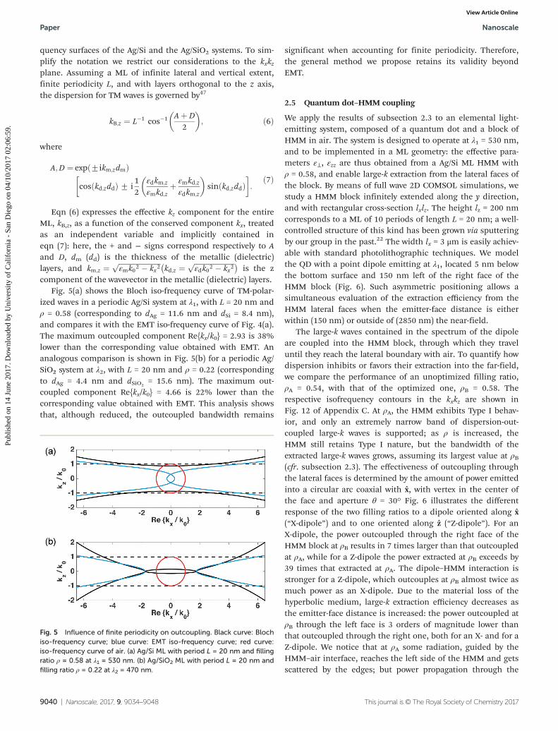
component of the wavevector in the metallic (dielectric) layers.Fig. 5(a) shows the Bloch iso-frequency curve of TM-polar-
ized waves in a periodic Ag/Si system at λ1, with L = 20 nm andρ = 0.58 (corresponding to dAg = 11.6 nm and dSi = 8.4 nm),and compares it with the EMT iso-frequency curve of Fig. 4(a).The maximum outcoupled component Re{kx/k0} = 2.93 is 38%lower than the corresponding value obtained with EMT. Ananalogous comparison is shown in Fig. 5(b) for a periodic Ag/SiO2 system at λ2, with L = 20 nm and ρ = 0.22 (correspondingto dAg = 4.4 nm and dSiO2
= 15.6 nm). The maximum out-coupled component Re{kx/k0} = 4.66 is 22% lower than thecorresponding value obtained with EMT. This analysis showsthat, although reduced, the outcoupled bandwidth remains
significant when accounting for finite periodicity. Therefore,the general method we propose retains its validity beyondEMT.
2.5 Quantum dot–HMM coupling
We apply the results of subsection 2.3 to an elemental light-emitting system, composed of a quantum dot and a block ofHMM in air. The system is designed to operate at λ1 = 530 nm,and to be implemented in a ML geometry: the effective para-meters ε⊥, εzz are thus obtained from a Ag/Si ML HMM withρ = 0.58, and enable large-k extraction from the lateral faces ofthe block. By means of full wave 2D COMSOL simulations, westudy a HMM block infinitely extended along the y direction,and with rectangular cross-section lxlz. The height lz = 200 nmcorresponds to a ML of 10 periods of length L = 20 nm; a well-controlled structure of this kind has been grown via sputteringby our group in the past.22 The width lx = 3 μm is easily achiev-able with standard photolithographic techniques. We modelthe QD with a point dipole emitting at λ1, located 5 nm belowthe bottom surface and 150 nm left of the right face of theHMM block (Fig. 6). Such asymmetric positioning allows asimultaneous evaluation of the extraction efficiency from theHMM lateral faces when the emitter-face distance is eitherwithin (150 nm) or outside of (2850 nm) the near-field.
The large-k waves contained in the spectrum of the dipoleare coupled into the HMM block, through which they traveluntil they reach the lateral boundary with air. To quantify howdispersion inhibits or favors their extraction into the far-field,we compare the performance of an unoptimized filling ratio,ρA = 0.54, with that of the optimized one, ρB = 0.58. Therespective isofrequency contours in the kxkz are shown inFig. 12 of Appendix C. At ρA, the HMM exhibits Type I behav-ior, and only an extremely narrow band of dispersion-out-coupled large-k waves is supported; as ρ is increased, theHMM still retains Type I nature, but the bandwidth of theextracted large-k waves grows, assuming its largest value at ρB(cfr. subsection 2.3). The effectiveness of outcoupling throughthe lateral faces is determined by the amount of power emittedinto a circular arc coaxial with x, with vertex in the center ofthe face and aperture θ = 30° Fig. 6 illustrates the differentresponse of the two filling ratios to a dipole oriented along x(“X-dipole”) and to one oriented along z (“Z-dipole”). For anX-dipole, the power outcoupled through the right face of theHMM block at ρB results in 7 times larger than that outcoupledat ρA, while for a Z-dipole the power extracted at ρB exceeds by39 times that extracted at ρA. The dipole–HMM interaction isstronger for a Z-dipole, which outcouples at ρB almost twice asmuch power as an X-dipole. Due to the material loss of thehyperbolic medium, large-k extraction efficiency decreases asthe emitter-face distance is increased: the power outcoupled atρB through the left face is 3 orders of magnitude lower thanthat outcoupled through the right one, both for an X- and for aZ-dipole. We notice that at ρA some radiation, guided by theHMM–air interface, reaches the left side of the HMM and getsscattered by the edges; but power propagation through the
Fig. 5 Influence of finite periodicity on outcoupling. Black curve: Blochiso-frequency curve; blue curve: EMT iso-frequency curve; red curve:iso-frequency curve of air. (a) Ag/Si ML with period L = 20 nm and fillingratio ρ = 0.58 at λ1 = 530 nm. (b) Ag/SiO2 ML with period L = 20 nm andfilling ratio ρ = 0.22 at λ2 = 470 nm.
Paper Nanoscale
9040 | Nanoscale, 2017, 9, 9034–9048 This journal is © The Royal Society of Chemistry 2017
Publ
ishe
d on
14
June
201
7. D
ownl
oade
d by
Uni
vers
ity o
f C
alif
orni
a -
San
Die
go o
n 04
/10/
2017
02:
06:5
9.
View Article Online
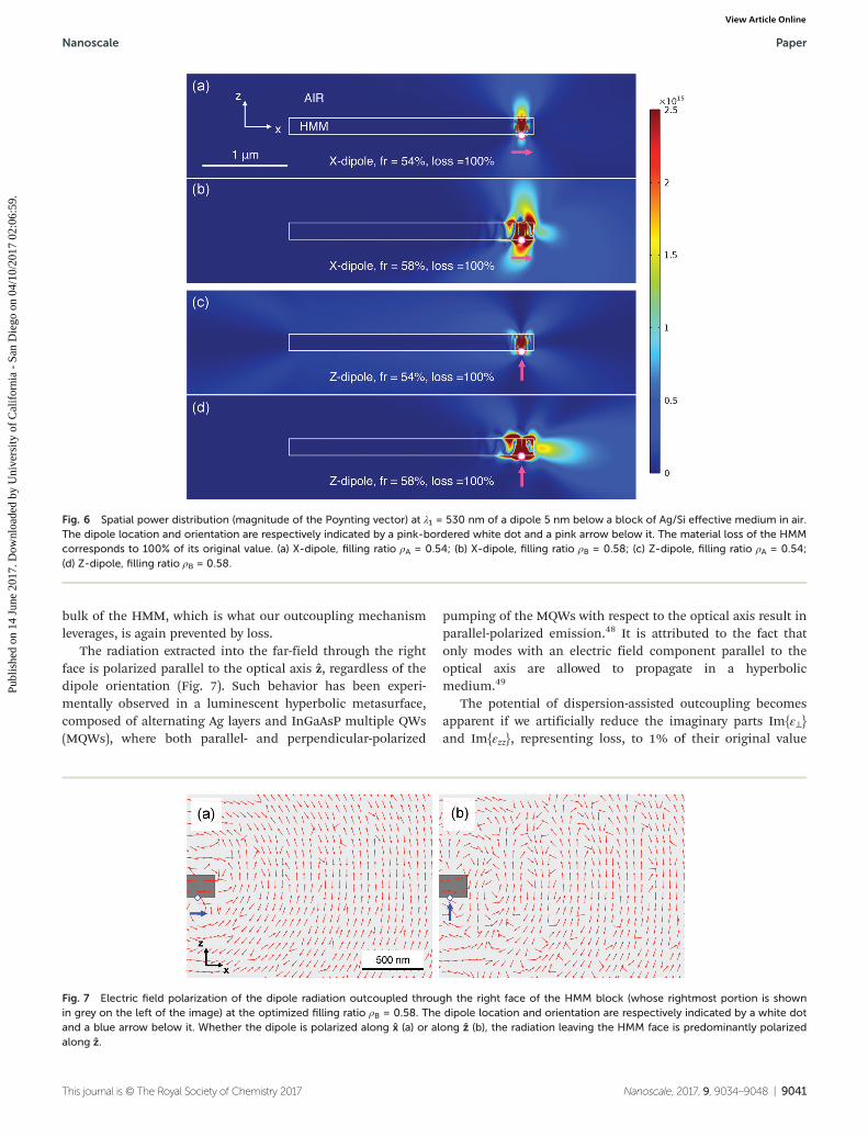
bulk of the HMM, which is what our outcoupling mechanismleverages, is again prevented by loss.
The radiation extracted into the far-field through the rightface is polarized parallel to the optical axis z, regardless of thedipole orientation (Fig. 7). Such behavior has been experi-mentally observed in a luminescent hyperbolic metasurface,composed of alternating Ag layers and InGaAsP multiple QWs(MQWs), where both parallel- and perpendicular-polarized
pumping of the MQWs with respect to the optical axis result inparallel-polarized emission.48 It is attributed to the fact thatonly modes with an electric field component parallel to theoptical axis are allowed to propagate in a hyperbolicmedium.49
The potential of dispersion-assisted outcoupling becomesapparent if we artificially reduce the imaginary parts Im{ε⊥}and Im{εzz}, representing loss, to 1% of their original value
Fig. 6 Spatial power distribution (magnitude of the Poynting vector) at λ1 = 530 nm of a dipole 5 nm below a block of Ag/Si effective medium in air.The dipole location and orientation are respectively indicated by a pink-bordered white dot and a pink arrow below it. The material loss of the HMMcorresponds to 100% of its original value. (a) X-dipole, filling ratio ρA = 0.54; (b) X-dipole, filling ratio ρB = 0.58; (c) Z-dipole, filling ratio ρA = 0.54;(d) Z-dipole, filling ratio ρB = 0.58.
Fig. 7 Electric field polarization of the dipole radiation outcoupled through the right face of the HMM block (whose rightmost portion is shownin grey on the left of the image) at the optimized filling ratio ρB = 0.58. The dipole location and orientation are respectively indicated by a white dotand a blue arrow below it. Whether the dipole is polarized along x (a) or along z (b), the radiation leaving the HMM face is predominantly polarizedalong z.
Nanoscale Paper
This journal is © The Royal Society of Chemistry 2017 Nanoscale, 2017, 9, 9034–9048 | 9041
Publ
ishe
d on
14
June
201
7. D
ownl
oade
d by
Uni
vers
ity o
f C
alif
orni
a -
San
Die
go o
n 04
/10/
2017
02:
06:5
9.
View Article Online
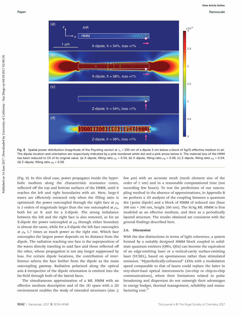
(Fig. 8). In this ideal case, power propagates inside the hyper-bolic medium along the characteristic resonance cones,reflected off the top and bottom surfaces of the HMM, until itreaches the left and right boundaries with air. Here, large-kwaves are efficiently extracted only when the filling ratio isoptimized: the power outcoupled through the right face at ρBis 3 orders of magnitude larger than the one outcoupled at ρA,both for an X- and for a Z-dipole. The strong imbalancebetween the left and the right face is also removed, as for anX-dipole the power outcoupled at ρB through either boundaryis almost the same, while for a Z-dipole the left face outcouplesat ρB 1.7 times as much power as the right one. Which faceoutcouples the largest power depends on its distance from thedipole. The radiation reaching one face is the superposition ofthe waves directly traveling to said face and those reflected offthe other, whose propagation is not any longer suppressed byloss. For certain dipole locations, the contribution of inter-ference selects the face farther from the dipole as the mainoutcoupling gateway. Radiation polarized along the opticalaxis z irrespective of the dipole orientation is emitted into thefar-field through both of the lateral faces.
The simultaneous approximation of a ML HMM with aneffective medium description and of the 3D space with a 2Denvironment enables the study of extended structures (size ≥
few μm) with an accurate mesh (mesh element size of theorder of 1 nm) and in a reasonable computational time (notexceeding few hours). To test the predictions of our outcou-pling method in the absence of approximations, in Appendix Bwe perform a 3D analysis of the coupling between a quantumdot (point dipole) and a block of HMM of reduced size (base300 nm × 300 nm, height 200 nm). The Si/Ag ML HMM is firstmodeled as an effective medium, and then as a periodicallylayered structure. The results obtained are consistent with thegeneral findings described here.
2.6. Discussion
With the due distinctions in terms of light coherence, a systemformed by a suitably designed HMM block coupled to solid-state quantum emitters (QWs, QDs) can become the equivalentof an edge-emitting laser or a vertical-cavity surface-emittinglaser (VCSEL), based on spontaneous rather than stimulatedemission. “Hyperbolically-enhanced” LEDs with a modulationspeed comparable to that of lasers could replace the latter invery-short-haul optical interconnects (on-chip or chip-to-chipcommunications), where their limitations related to pulsebroadening and dispersion do not outweigh their advantagesin energy budget, thermal management, reliability and manu-facturing cost.27
Fig. 8 Spatial power distribution (magnitude of the Poynting vector) at λ1 = 530 nm of a dipole 5 nm below a block of Ag/Si effective medium in air.The dipole location and orientation are respectively indicated by a pink-bordered white dot and a pink arrow below it. The material loss of the HMMhas been reduced to 1% of its original value. (a) X-dipole, filling ratio ρA = 0.54; (b) X-dipole, filling ratio ρB = 0.58; (c) Z-dipole, filling ratio ρA = 0.54;(d) Z-dipole, filling ratio ρB = 0.58.
Paper Nanoscale
9042 | Nanoscale, 2017, 9, 9034–9048 This journal is © The Royal Society of Chemistry 2017
Publ
ishe
d on
14
June
201
7. D
ownl
oade
d by
Uni
vers
ity o
f C
alif
orni
a -
San
Die
go o
n 04
/10/
2017
02:
06:5
9.
View Article Online
Our analysis showed that ML HMMs naturally support sideemission, but are not suited for top emission. In addition, asobserved in the previous subsection, the intrinsic loss of con-stituent materials restricts efficient outcoupling to those emit-ters in the near field of the side interface. These two con-straints can be relaxed simultaneously by fabricating the MLinto vertical lamellae, where the non-metallic constituent is again medium such as a semiconductor MQW. A configurationof this kind was recently demonstrated with a Ag/InGaAsPsystem.48,50–53 Operating in the 1200 nm–1600 nm spectralrange, the structure exhibits narrow bands of large-k wavesthat outcouple to air without the need for a grating, for thereasons theoretically explained in the present work. Anotherdesign that meets the top emission and efficient outcouplingrequirements exploits a hyperlens-like geometry: the layershere are arranged in a concentric semi-spherical or semi-cylindrical stack, contained in the z < 0 region and comprisedbetween the external and internal radii rext and rint, and thesurface of the innermost layer is coated with QDs. Providedthat rext is within the near field of the emitters, radiation fromthe QDs couples to the HMM, shortly travels along the direc-tion tangential to the layers without experiencing excessiveattenuation and gets extracted along the z axis. An alternativeapproach to achieve top emission consists in growing the MLon the side walls of a vertical nanowire light-emitting structurethat incorporates one or more MQWs; the geometry of thenanowires and of the MQWs can be adjusted, as shown in (ref.54) for blue/green-emitting III-nitride semiconductor nano-wires, to boost the emitter–ML interaction and optimize theoutcoupling efficiency. Top emission is convenient from amanufacturing standpoint: while edge-emitting devices grownon a wafer must be first diced in sub-units and then testedindividually, surface-emitting ones can be tested all at once onthe wafer where they are fabricated. Side emission however isdesirable for on-chip or chip-to-chip communication, andenables direct light coupling into waveguide-like planardevices. In order to maintain a HMM feature size compatiblewith photolithography, without limiting efficient outcouplingto the emitters closer to the side faces, the imaginary com-ponent of the constituent permittivities can be minimizedwith low-loss materials55,56 or compensated for with gain. vander Waals heterostructures, built with single-atomic layermaterials (“2D crystals”) including graphene, hexagonal boronnitride (hBN) and 2D oxides,57 can incorporate atomic mono-layers of transition metal dichalcogenides such as tungstendiselenide (WSe2) and tungsten disulfide (WS2) as activemedia.58,59 Heterostructures based on hBN, a natural HMM,60
or on ultra-thin MLs with 2D active layers, can greatly reduceloss and fully leverage our light extraction method, since theirsize forbids grating inscription as a practical option. Finally,hybrid ML-NW geometries, or MLs with atomically thin met-allic films subject to quantum confinement, might elude withtheir dispersion the guidelines traced in subsection 2.2.
The feasibility of our approach relies on the exact control ofthe filling ratio. In the visible range, the ML period must notexceed few tens of nanometers in order to be sub-wavelength
(and therefore justify the effective medium approximation).Metallic films for operations at visible wavelengths are typicallygrown by DC sputtering or e-beam evaporation. In either case,at thicknesses of 10 nm or less, the metal forms islands,rather than a uniform layer. While the size and shape of thegrains can be controlled to some extent by tuning the depo-sition parameters, the resulting morphology intrinsicallyyields a space-dependent filling ratio. Therefore, the effectiveHMM parameters need to have a good tolerance with ρ vari-ations, to preserve the applicability of our model. This rep-resents less of a concern for HMMs in the infrared (IR) range:NW and ML systems can be grown with sub-nanometer accu-racy via atomic layer deposition (ALD) and chemical vapordeposition (CVD),56,61 and periods of several tens of nm arealready well sub-wavelength. IR HMMs hence constitute apromising candidate for early experimental testing. A dynamicfine-tuning of the filling ratio from non-outcoupling to out-coupling, detectable as an enhanced directionality of the emissionpattern, can be performed in voltage-controlled HMMs.60,62,63
An emitter–HMM system suitable for optical communi-cation should simultaneously maximize, at a given wavelength,the far-field power extracted into a preferential direction andthe PF, which determines the modulation bandwidth enhance-ment. However, the filling ratios that optimize both quantitiesin general do not coincide. A recent work suggests tapering ahyperbolic ML block to adiabatically outcouple large-k wavesfrom its side.40 According to that approach, we could design aHMM with filling ratio varying from ρ1 (in the proximity of theemitter) to ρ2 (away from the emitter), to first maximize the PFand then the outcoupling. Such transition however musthappen over a space scale of few microns, which imposes aconstraint on the device size. In addition, power extraction islimited to the tapering direction, making the mechanisminefficient. Finally, the shadowed deposition technique uti-lized seems impractical in an industrial context. We proposeinstead to keep a single-ρ design, that achieves a balanced per-formance between outcoupling and PF. Optimization methodscan be developed to tune this trade-off, which we believe is themost viable solution in a mass production perspective.
3 Conclusions
The present work introduced a systematic approach to extractlarge-k waves from HMMs without the use of a grating. Thisnovel method relies on dispersion engineering, and is appli-cable to any medium, natural or artificial, described by ahyperbolic permittivity tensor. Extraction of a large-k waveband from the top or from the side faces of the HMM isachieved, as summarized in Table 1, in the ENZ regime ofeither permittivity component. Loss in the effective medium,dictated both by the loss and the ML or NW arrangement of itsconstituent materials, selects the preferential outcoupling con-figuration: side outcoupling for ML HMMs, top outcouplingfor NW HMMs. We provided guidelines to maximize the extentof the large-k wave band extracted through the top or side
Nanoscale Paper
This journal is © The Royal Society of Chemistry 2017 Nanoscale, 2017, 9, 9034–9048 | 9043
Publ
ishe
d on
14
June
201
7. D
ownl
oade
d by
Uni
vers
ity o
f C
alif
orni
a -
San
Die
go o
n 04
/10/
2017
02:
06:5
9.
View Article Online
faces, and we applied them to the optimization of a Ag/Si anda Ag/SiO2 ML HMM, respectively at λ1 = 530 nm and λ2 =470 nm. We further discussed how the effective mediumdescription moderately overestimates the outcoupled band-width, when the finite periodicity of practical HMM realiz-ations is taken into account. We finally studied a QD-Ag/Si MLHMM system at λ1, modeling the hyperbolic medium both asan effective medium and as a multilayered structure. For a 3Dblock of Ag/Si layered medium, we observed a 6-fold increasein lateral power extraction at an optimized filling ratio com-pared to an unoptimized one.
Future work will explore different material combinationsfor ML HMMs, with the goal of optimizing lateral extraction atstandard IR wavelengths for fiber-optic communication. Inparallel, NW HMMs will be studied in view of designing anemitter–HMM system for top outcoupling.
AppendixA. Limit cases of hyperbolic dispersion
A hyperbola in the xz plane with center in the origin and ver-tices on the x axis is described by the equation
x2
a2� z2
b2¼ 1; ð8Þ
where a (semi-major axis) is the distance between a vertex andthe origin, and b (semi-minor axis) is the distance between avertex and the asymptote above (or below) it. While a alonedetermines the separation of the hyperbola branches from thez axis, by defining the coordinates of the vertices (x, z) = (±a, 0),the ratio of b to a controls the curvature of the branches at thevertices. The latter is expressed in terms of the eccentricity
e ¼ffiffiffiffiffiffiffiffiffiffiffiffiffiffiffiffiffiffiffiffi1þ b
a
� �2s
; ð9Þ
a positive quantity with limiting values of 1 to +∞. Theseextreme values are reached by
limba!0þ
e ¼ 1; limba!þ1
e ¼ þ1; ð10; 11Þ
corresponding to cases of maximal and minimal curvature,respectively.
Let us consider a lossless HMM of Type II (εzz > 0 and ε⊥ <0). Its dispersion is described by eqn (8), provided that the fol-lowing substitutions are made:
x ! kx=k0 a2 ! εzzz ! kz=k0 b2 ! jε?j; ð12Þ
For top outcoupling, kx is conserved, and large kHMM,z com-ponents can be extracted (Fig. 3(c) of main text). Following themain text, we restrict our analysis to the (kx > 0, kz > 0) quad-rant. The limit case in which an infinite band of waves propa-gating within the HMM is converted to propagating waves inair occurs when two conditions are simultaneously verified:the branches of the hyperbola must be “straightened” until
their curvature at the vertices vanishes and they align with thez axis, and “squeezed” along the x axis, until the vertex coordi-nate a becomes <1. The first requirement ensures the infiniteextension of the band, the second forces all the kx componentsof the band to be identical to a certain kx < k0. This, by virtueof eqn (5), preserves the propagating nature of all the k-vectorsin the band across the HMM–air interface. It also implies avanishing angular spread in the emission, as all the waves inthe HMM are refracted into air only at one specific angle withthe z axis, θair ¼ arctan ðkx=
ffiffiffiffiffiffiffiffiffiffiffiffiffiffiffiffiffiffiffik02 � kx2
pÞ. Squeezing is maxi-
mized when kx = 0: in that case, the two straight branches col-lapse onto the z axis, θair = 0 and the emission is orthogonal tothe interface. The band edges kHMM,1 and kHMM,2 and the vectorkHMM,sep separating the short- and large-k constituents of theband (cfr. main text) have zero x components, and z com-ponents kHMM,1z = 0, kHMM,2z = +∞ and kHMM,sep z = k0. The sim-ultaneous requests of infinite bandwidth (i.e. maximal straigh-tening, or vanishing curvature at vertices) and normal emission(i.e. maximal squeezing, or vertices coinciding with the origin),are formulated by means of eqn (9) and (11) as follows:
ba! þ1
a ! 0þ
(ð12Þ,
ffiffiffiffiffiffiffiffijε?jεzz
r! þ1ffiffiffiffiffiffi
εzzp ! 0þ:
8<: ð13Þ
We look for physical solutions of the system, namely finiteor vanishing values of |ε⊥| and εzz. The second equationdemands that, at a fixed frequency ω, the filling ratio ρ take avalue ρ such that εzz(ρ) → 0+ as ρ → ρ. The first equation is sim-ultaneously satisfied if, as ρ → ρ, |ε⊥(ρ)| either approaches afinite value |ε⊥(ρ)| or approaches 0 less quickly than εzz(ρ)does: in mathematical terms, εzz(ρ) = o(|ε⊥(ρ)|) as ρ → ρ.
For side outcoupling, kz is conserved, and large kHMM,x com-ponents can be extracted (Fig. 3(d) of main text). Restrictingour analysis to the (kx < 0, kz > 0) quadrant, the band edgeskHMM,1 and kHMM,2 and the separation vector kHMM,sep areredefined as the intersections of the hyperbolic iso-frequencycurve respectively with the x axis, the straight line kz ≡ k0 andthe circular iso-frequency curve of air. In the considered con-figuration, both maximal straightening and maximal squeez-ing are accomplished by solely requesting that the curvature atvertices be infinity: by means of eqn (9) and (10), this reads
ba! 0þ ð12Þ
, ffiffiffiffiffiffiffiffijε?jεzz
r! 0þ: ð14Þ
Eqn (14) is satisfied when, at a fixed frequency ω, the fillingratio ρ takes a value ρ such that |ε⊥(ρ)| → 0+ and |ε⊥(ρ)| =o(εzz(ρ)) as ρ → ρ (we discarded the unphysical solution εzz(ρ)→ +∞, and |ε⊥(ρ)| → |ε⊥(ρ)| finite or |ε⊥(ρ)| → +∞ slower thanεzz(ρ)). The latter condition implies that εzz(ρ) eitherapproaches 0 less quickly than |ε⊥(ρ)| does, or approaches afinite value εzz(ρ). In the first case, kHMM,1, kHMM,sep andkHMM,2 have zero z components, and x components kHMM,1x =0, kHMM,sep x = k0 and kHMM,2x = +∞. In the second case, all thez components remain zero and it is still kHMM,2x = +∞, butkHMM;1x ¼
ffiffiffiffiffiffiffiffiffiffiffiffiεzzðρÞ
pk0 and kHMM, sep x depends on εzz(ρ): if εzz(ρ)
Paper Nanoscale
9044 | Nanoscale, 2017, 9, 9034–9048 This journal is © The Royal Society of Chemistry 2017
Publ
ishe
d on
14
June
201
7. D
ownl
oade
d by
Uni
vers
ity o
f C
alif
orni
a -
San
Die
go o
n 04
/10/
2017
02:
06:5
9.
View Article Online
≤ 1, kHMM,sep x = k0, while if εzz(ρ) > 1 kHMM,sep x and thereforekHMM,sep do not exist, as the hyperbolic and circular iso-fre-quency curves do not intersect (outcoupled band exclusivelycomposed of large-k waves).
Let us now consider a lossless HMM of Type I (εzz < 0 andε⊥ > 0). By means of the substitutions
x ! kx=k0 a2 ! �jεzzjz ! kz=k0 b2 ! �ε?;
ð15Þ
we can rewrite eqn (8) as
� x2
a′2þ z2
b′2¼ 1; ð16Þ
where we renamed
jεzzj ! a′2 ε? ! b′2: ð17ÞEqn (15)–(17) describe a dispersion of Type I. The change of
signs in the left side of eqn (16) corresponds to a 90° rotationof the hyperbola, whose vertices now lie on the z axis. Identicalconsiderations to those just discussed for Type II thereforeapply to Type I, keeping in mind that the behavior of top andside outcoupling is now swapped by cause of the rotation. Fortop outcoupling, an infinite bandwidth of k-vectors is ortho-gonally extracted through the top HMM–air boundary when, atfixed ω, the filling ratio ρ takes a value ρ such that |εzz(ρ)| → 0+
and |εzz(ρ)| = o(ε⊥(ρ)) as ρ → ρ. For side outcoupling, an infi-nite bandwidth of k-vectors is orthogonally extracted throughthe side HMM–air interface, for a given ω, at ρ such that ε⊥(ρ)→ 0+ and ε⊥(ρ) = o(|εzz(ρ)|) as ρ → ρ.
B. Quantum dot–HMM coupling: 3D study
In the present appendix we extend the analysis of the QD–HMM system performed in subsection 2.5 to a full 3D simu-lation environment. As the dimensionality increases, so domemory requirements, imposing a concomitant decrease ofthe domain size if the computational time is to remain finite.We therefore consider a block of HMM with identical height tothe 2D structure (lz = 200 nm), but with shortened widthcoincident with the length lx = ly = 300 nm. To maximize theanalogy with the 2D case, we locate a point dipole emitting atλ1 5 nm below the center of the bottom surface, so that its dis-tance from each lateral surface is 150 nm. The power emittedthrough a lateral face is collected into a spherical cap coaxialwith x (for the faces parallel to the yz plane) or y (for the facesparallel to the xz plane), with vertex in the center of the faceand aperture θ = 30°. Symmetry reduces all the dipole-lateralface permutations to 3 geometries: X-dipole, power outcoupledthrough face yz (PX, yz); X-dipole, power outcoupled throughface xz (PX, xz); and Z-dipole, power outcoupled through any ofthe lateral faces (PZ).
We first model the Si/Ag HMM as an effective medium. Thepowers PX, yz and PZ at the optimized filling ratio ρB arerespectively 4 and 31 times larger than at the unoptimizedfilling ratio ρA, a proportion close to that of the correspondent2D enhancements (subsection 2.5). The power PX,xz which
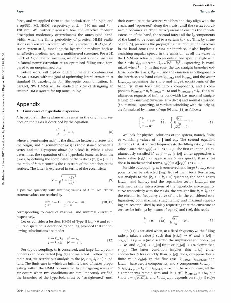
lacks of a 2D counterpart, results comparable for the twofilling ratios. The lateral power extraction for a Z-dipolecoupled to an EMT block with filling ratio ρB is visualized inFig. 9.
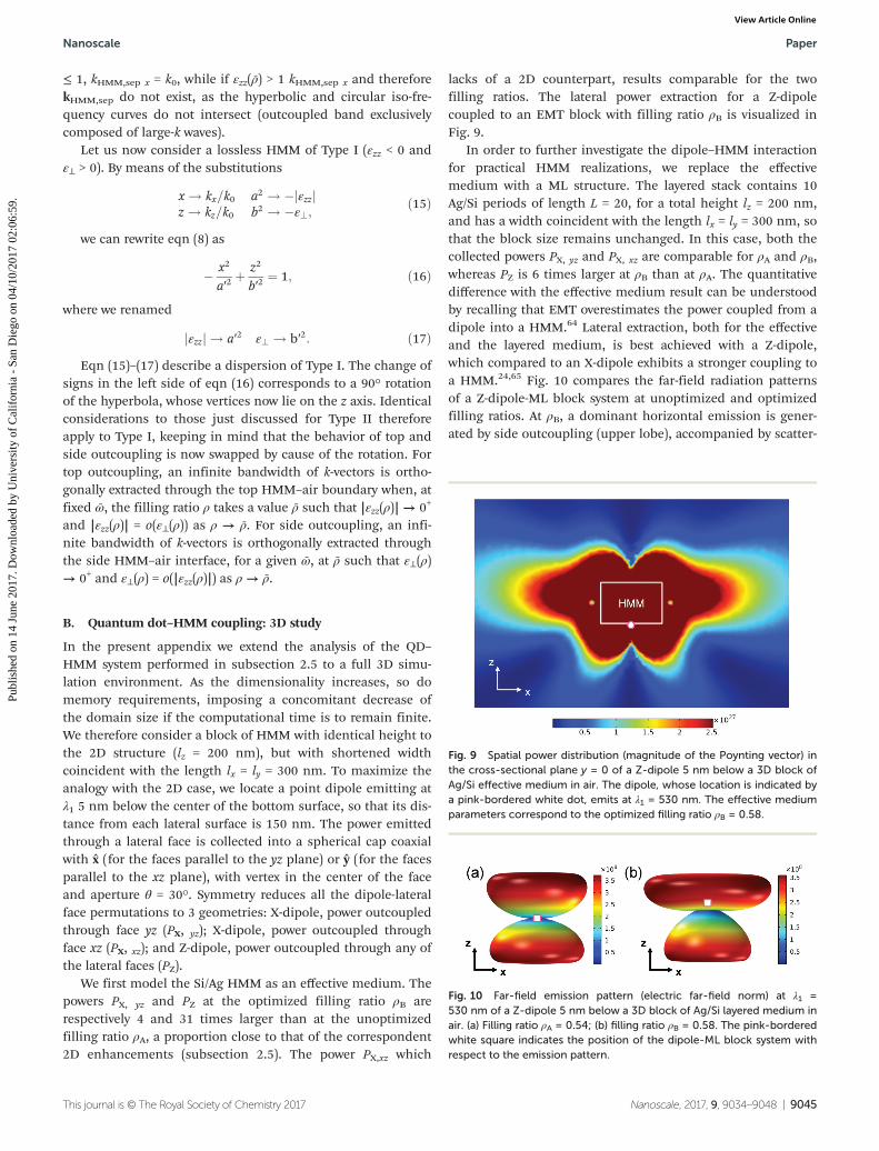
In order to further investigate the dipole–HMM interactionfor practical HMM realizations, we replace the effectivemedium with a ML structure. The layered stack contains 10Ag/Si periods of length L = 20, for a total height lz = 200 nm,and has a width coincident with the length lx = ly = 300 nm, sothat the block size remains unchanged. In this case, both thecollected powers PX, yz and PX, xz are comparable for ρA and ρB,whereas PZ is 6 times larger at ρB than at ρA. The quantitativedifference with the effective medium result can be understoodby recalling that EMT overestimates the power coupled from adipole into a HMM.64 Lateral extraction, both for the effectiveand the layered medium, is best achieved with a Z-dipole,which compared to an X-dipole exhibits a stronger coupling toa HMM.24,65 Fig. 10 compares the far-field radiation patternsof a Z-dipole-ML block system at unoptimized and optimizedfilling ratios. At ρB, a dominant horizontal emission is gener-ated by side outcoupling (upper lobe), accompanied by scatter-
Fig. 9 Spatial power distribution (magnitude of the Poynting vector) inthe cross-sectional plane y = 0 of a Z-dipole 5 nm below a 3D block ofAg/Si effective medium in air. The dipole, whose location is indicated bya pink-bordered white dot, emits at λ1 = 530 nm. The effective mediumparameters correspond to the optimized filling ratio ρB = 0.58.
Fig. 10 Far-field emission pattern (electric far-field norm) at λ1 =530 nm of a Z-dipole 5 nm below a 3D block of Ag/Si layered medium inair. (a) Filling ratio ρA = 0.54; (b) filling ratio ρB = 0.58. The pink-borderedwhite square indicates the position of the dipole-ML block system withrespect to the emission pattern.
Nanoscale Paper
This journal is © The Royal Society of Chemistry 2017 Nanoscale, 2017, 9, 9034–9048 | 9045
Publ
ishe
d on
14
June
201
7. D
ownl
oade
d by
Uni
vers
ity o
f C
alif
orni
a -
San
Die
go o
n 04
/10/
2017
02:
06:5
9.
View Article Online
ing from the lower block edges closer to the dipole (lowerlobe). At ρA instead, two lobes symmetrically departing fromthe dipole-ML block system indicate that the main light extrac-tion mechanism is scattering from the upper and lower edgesof the block, rather than outcoupling from the lateral faces.
C. Additional plots for the Ag/Si and Ag/SiO2 systems
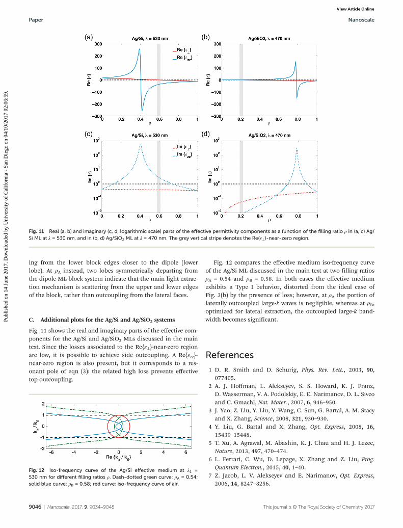
Fig. 11 shows the real and imaginary parts of the effective com-ponents for the Ag/Si and Ag/SiO2 MLs discussed in the maintext. Since the losses associated to the Re{ε⊥}-near-zero regionare low, it is possible to achieve side outcoupling. A Re{εzz}-near-zero region is also present, but it corresponds to a res-onant pole of eqn (3): the related high loss prevents effectivetop outcoupling.
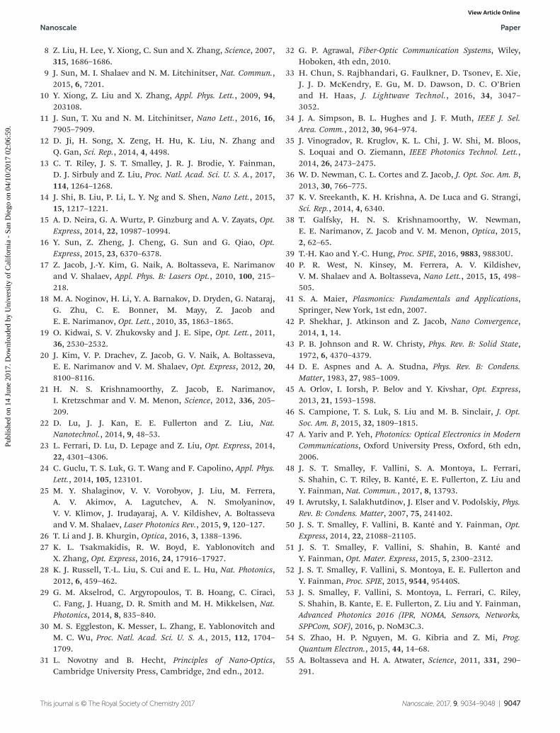
Fig. 12 compares the effective medium iso-frequency curveof the Ag/Si ML discussed in the main text at two filling ratiosρA = 0.54 and ρB = 0.58. In both cases the effective mediumexhibits a Type I behavior, distorted from the ideal case ofFig. 3(b) by the presence of loss; however, at ρA the portion oflaterally outcoupled large-k waves is negligible, whereas at ρB,optimized for lateral extraction, the outcoupled large-k band-width becomes significant.
References
1 D. R. Smith and D. Schurig, Phys. Rev. Lett., 2003, 90,077405.
2 A. J. Hoffman, L. Alekseyev, S. S. Howard, K. J. Franz,D. Wasserman, V. A. Podolskiy, E. E. Narimanov, D. L. Sivcoand C. Gmachl, Nat. Mater., 2007, 6, 946–950.
3 J. Yao, Z. Liu, Y. Liu, Y. Wang, C. Sun, G. Bartal, A. M. Stacyand X. Zhang, Science, 2008, 321, 930–930.
4 Y. Liu, G. Bartal and X. Zhang, Opt. Express, 2008, 16,15439–15448.
5 T. Xu, A. Agrawal, M. Abashin, K. J. Chau and H. J. Lezec,Nature, 2013, 497, 470–474.
6 L. Ferrari, C. Wu, D. Lepage, X. Zhang and Z. Liu, Prog.Quantum Electron., 2015, 40, 1–40.
7 Z. Jacob, L. V. Alekseyev and E. Narimanov, Opt. Express,2006, 14, 8247–8256.
Fig. 11 Real (a, b) and imaginary (c, d, logarithmic scale) parts of the effective permittivity components as a function of the filling ratio ρ in (a, c) Ag/Si ML at λ = 530 nm, and in (b, d) Ag/SiO2 ML at λ = 470 nm. The grey vertical stripe denotes the Re{ε⊥}-near-zero region.
Fig. 12 Iso-frequency curve of the Ag/Si effective medium at λ1 =530 nm for different filling ratios ρ. Dash-dotted green curve: ρA = 0.54;solid blue curve: ρB = 0.58; red curve: iso-frequency curve of air.
Paper Nanoscale
9046 | Nanoscale, 2017, 9, 9034–9048 This journal is © The Royal Society of Chemistry 2017
Publ
ishe
d on
14
June
201
7. D
ownl
oade
d by
Uni
vers
ity o
f C
alif
orni
a -
San
Die
go o
n 04
/10/
2017
02:
06:5
9.
View Article Online
8 Z. Liu, H. Lee, Y. Xiong, C. Sun and X. Zhang, Science, 2007,315, 1686–1686.
9 J. Sun, M. I. Shalaev and N. M. Litchinitser, Nat. Commun.,2015, 6, 7201.
10 Y. Xiong, Z. Liu and X. Zhang, Appl. Phys. Lett., 2009, 94,203108.
11 J. Sun, T. Xu and N. M. Litchinitser, Nano Lett., 2016, 16,7905–7909.
12 D. Ji, H. Song, X. Zeng, H. Hu, K. Liu, N. Zhang andQ. Gan, Sci. Rep., 2014, 4, 4498.
13 C. T. Riley, J. S. T. Smalley, J. R. J. Brodie, Y. Fainman,D. J. Sirbuly and Z. Liu, Proc. Natl. Acad. Sci. U. S. A., 2017,114, 1264–1268.
14 J. Shi, B. Liu, P. Li, L. Y. Ng and S. Shen, Nano Lett., 2015,15, 1217–1221.
15 A. D. Neira, G. A. Wurtz, P. Ginzburg and A. V. Zayats, Opt.Express, 2014, 22, 10987–10994.
16 Y. Sun, Z. Zheng, J. Cheng, G. Sun and G. Qiao, Opt.Express, 2015, 23, 6370–6378.
17 Z. Jacob, J.-Y. Kim, G. Naik, A. Boltasseva, E. Narimanovand V. Shalaev, Appl. Phys. B: Lasers Opt., 2010, 100, 215–218.
18 M. A. Noginov, H. Li, Y. A. Barnakov, D. Dryden, G. Nataraj,G. Zhu, C. E. Bonner, M. Mayy, Z. Jacob andE. E. Narimanov, Opt. Lett., 2010, 35, 1863–1865.
19 O. Kidwai, S. V. Zhukovsky and J. E. Sipe, Opt. Lett., 2011,36, 2530–2532.
20 J. Kim, V. P. Drachev, Z. Jacob, G. V. Naik, A. Boltasseva,E. E. Narimanov and V. M. Shalaev, Opt. Express, 2012, 20,8100–8116.
21 H. N. S. Krishnamoorthy, Z. Jacob, E. Narimanov,I. Kretzschmar and V. M. Menon, Science, 2012, 336, 205–209.
22 D. Lu, J. J. Kan, E. E. Fullerton and Z. Liu, Nat.Nanotechnol., 2014, 9, 48–53.
23 L. Ferrari, D. Lu, D. Lepage and Z. Liu, Opt. Express, 2014,22, 4301–4306.
24 C. Guclu, T. S. Luk, G. T. Wang and F. Capolino, Appl. Phys.Lett., 2014, 105, 123101.
25 M. Y. Shalaginov, V. V. Vorobyov, J. Liu, M. Ferrera,A. V. Akimov, A. Lagutchev, A. N. Smolyaninov,V. V. Klimov, J. Irudayaraj, A. V. Kildishev, A. Boltassevaand V. M. Shalaev, Laser Photonics Rev., 2015, 9, 120–127.
26 T. Li and J. B. Khurgin, Optica, 2016, 3, 1388–1396.27 K. L. Tsakmakidis, R. W. Boyd, E. Yablonovitch and
X. Zhang, Opt. Express, 2016, 24, 17916–17927.28 K. J. Russell, T.-L. Liu, S. Cui and E. L. Hu, Nat. Photonics,
2012, 6, 459–462.29 G. M. Akselrod, C. Argyropoulos, T. B. Hoang, C. Ciracì,
C. Fang, J. Huang, D. R. Smith and M. H. Mikkelsen, Nat.Photonics, 2014, 8, 835–840.
30 M. S. Eggleston, K. Messer, L. Zhang, E. Yablonovitch andM. C. Wu, Proc. Natl. Acad. Sci. U. S. A., 2015, 112, 1704–1709.
31 L. Novotny and B. Hecht, Principles of Nano-Optics,Cambridge University Press, Cambridge, 2nd edn., 2012.
32 G. P. Agrawal, Fiber-Optic Communication Systems, Wiley,Hoboken, 4th edn, 2010.
33 H. Chun, S. Rajbhandari, G. Faulkner, D. Tsonev, E. Xie,J. J. D. McKendry, E. Gu, M. D. Dawson, D. C. O’Brienand H. Haas, J. Lightwave Technol., 2016, 34, 3047–3052.
34 J. A. Simpson, B. L. Hughes and J. F. Muth, IEEE J. Sel.Area. Comm., 2012, 30, 964–974.
35 J. Vinogradov, R. Kruglov, K. L. Chi, J. W. Shi, M. Bloos,S. Loquai and O. Ziemann, IEEE Photonics Technol. Lett.,2014, 26, 2473–2475.
36 W. D. Newman, C. L. Cortes and Z. Jacob, J. Opt. Soc. Am. B,2013, 30, 766–775.
37 K. V. Sreekanth, K. H. Krishna, A. De Luca and G. Strangi,Sci. Rep., 2014, 4, 6340.
38 T. Galfsky, H. N. S. Krishnamoorthy, W. Newman,E. E. Narimanov, Z. Jacob and V. M. Menon, Optica, 2015,2, 62–65.
39 T.-H. Kao and Y.-C. Hung, Proc. SPIE, 2016, 9883, 98830U.40 P. R. West, N. Kinsey, M. Ferrera, A. V. Kildishev,
V. M. Shalaev and A. Boltasseva, Nano Lett., 2015, 15, 498–505.
41 S. A. Maier, Plasmonics: Fundamentals and Applications,Springer, New York, 1st edn, 2007.
42 P. Shekhar, J. Atkinson and Z. Jacob, Nano Convergence,2014, 1, 14.
43 P. B. Johnson and R. W. Christy, Phys. Rev. B: Solid State,1972, 6, 4370–4379.
44 D. E. Aspnes and A. A. Studna, Phys. Rev. B: Condens.Matter, 1983, 27, 985–1009.
45 A. Orlov, I. Iorsh, P. Belov and Y. Kivshar, Opt. Express,2013, 21, 1593–1598.
46 S. Campione, T. S. Luk, S. Liu and M. B. Sinclair, J. Opt.Soc. Am. B, 2015, 32, 1809–1815.
47 A. Yariv and P. Yeh, Photonics: Optical Electronics in ModernCommunications, Oxford University Press, Oxford, 6th edn,2006.
48 J. S. T. Smalley, F. Vallini, S. A. Montoya, L. Ferrari,S. Shahin, C. T. Riley, B. Kanté, E. E. Fullerton, Z. Liu andY. Fainman, Nat. Commun., 2017, 8, 13793.
49 I. Avrutsky, I. Salakhutdinov, J. Elser and V. Podolskiy, Phys.Rev. B: Condens. Matter, 2007, 75, 241402.
50 J. S. T. Smalley, F. Vallini, B. Kanté and Y. Fainman, Opt.Express, 2014, 22, 21088–21105.
51 J. S. T. Smalley, F. Vallini, S. Shahin, B. Kanté andY. Fainman, Opt. Mater. Express, 2015, 5, 2300–2312.
52 J. S. T. Smalley, F. Vallini, S. Montoya, E. E. Fullerton andY. Fainman, Proc. SPIE, 2015, 9544, 95440S.
53 J. S. Smalley, F. Vallini, S. Montoya, L. Ferrari, C. Riley,S. Shahin, B. Kante, E. E. Fullerton, Z. Liu and Y. Fainman,Advanced Photonics 2016 (IPR, NOMA, Sensors, Networks,SPPCom, SOF), 2016, p. NoM3C.3.
54 S. Zhao, H. P. Nguyen, M. G. Kibria and Z. Mi, Prog.Quantum Electron., 2015, 44, 14–68.
55 A. Boltasseva and H. A. Atwater, Science, 2011, 331, 290–291.
Nanoscale Paper
This journal is © The Royal Society of Chemistry 2017 Nanoscale, 2017, 9, 9034–9048 | 9047
Publ
ishe
d on
14
June
201
7. D
ownl
oade
d by
Uni
vers
ity o
f C
alif
orni
a -
San
Die
go o
n 04
/10/
2017
02:
06:5
9.
View Article Online

56 C. T. Riley, J. S. T. Smalley, K. W. Post, D. N. Basov,Y. Fainman, D. Wang, Z. Liu and D. J. Sirbuly, Small, 2016,12, 892–901.
57 A. K. Geim and I. V. Grigorieva, Nature, 2013, 499,419–425.
58 G. Clark, J. R. Schaibley, J. Ross, T. Taniguchi,K. Watanabe, J. R. Hendrickson, S. Mou, W. Yao and X. Xu,Nano Lett., 2016, 16, 3944–3948.
59 A. K. Geim and I. V. Grigorieva, Nature, 2013, 499,419–425.
60 S. Dai, Q. Ma, M. K. Liu, T. Andersen, Z. Fei,M. D. Goldflam, M. Wagner, K. Watanabe, T. Taniguchi,M. Thiemens, F. Keilmann, G. C. A. M. Janssen, S.-E. Zhu,
P. Jarillo-Herrero, M. M. Fogler and D. N. Basov, Nat.Nanotechnol., 2015, 10, 682–686.
61 Y.-C. Chang, C.-H. Liu, C.-H. Liu, S. Zhang, S. R. Marder,E. E. Narimanov, Z. Zhong and T. B. Norris, Nat. Commun.,2016, 7, 10568.
62 G. T. Papadakis and H. A. Atwater, Phys. Rev. B: Condens.Matter, 2015, 92, 184101.
63 S. Prayakarao, B. Mendoza, A. Devine, C. Kyaw, R. B. vanDover, V. Liberman and M. A. Noginov, Appl. Phys. Lett.,2016, 109, 061105.
64 C. Guclu, S. Campione and F. Capolino, Phys. Rev. B:Condens. Matter, 2012, 86, 205130.
65 W. L. Barnes, J. Mod. Opt., 1998, 45, 661–699.
Paper Nanoscale
9048 | Nanoscale, 2017, 9, 9034–9048 This journal is © The Royal Society of Chemistry 2017
Publ
ishe
d on
14
June
201
7. D
ownl
oade
d by
Uni
vers
ity o
f C
alif
orni
a -
San
Die
go o
n 04
/10/
2017
02:
06:5
9.
View Article Online


![Hyperbolic metamaterials based on quantum-dot plasmon ... · multilayers [3,4] and nanorod arrays [2,18] have been shown to possess salient properties of HMMs in a broad frequency](https://img.dokumen.tips/doc/110x75/5e326c0e22e5a92c343460c8/hyperbolic-metamaterials-based-on-quantum-dot-plasmon-multilayers-34-and.jpg)


![REVIEW Open Access Hyperbolic metamaterials: fundamentals … · 2017-08-29 · metamaterial for practical applications [39]. A wide choice of plasmonic metals and high index di-electrics](https://img.dokumen.tips/doc/110x75/5f38753a5800ec081178e5da/review-open-access-hyperbolic-metamaterials-fundamentals-2017-08-29-metamaterial.jpg)