Embed Size (px)
Citation preview
Hydroxyapatite Microparticles asFeedback-Active Reservoirs of CorrosionInhibitorsD. Snihirova,† S. V. Lamaka,*,† M. Taryba,† A. N. Salak,‡ S. Kallip,‡ M. L. Zheludkevich,‡M. G. S. Ferreira,†,‡ and M. F. Montemor†
ICEMS, Instituto Superior Tecnico, UTL, Avenida Rovisco Pais, 1049-001 Lisbon, Portugal, and CICECO, Dep. ofCeramics and Glass Engineering, University of Aveiro, 3810-193 Aveiro, Portugal
ABSTRACT This work contributes to the development of new feedback-active anticorrosion systems. Inhibitor-doped hydroxyapatitemicroparticles (HAP) are used as reservoirs, storing corrosion inhibitor to be released on demand. Release of the entrapped inhibitoris triggered by redox reactions associated with the corrosion process. HAP were used as reservoirs for several inhibiting species:cerium(III), lanthanum(III), salicylaldoxime, and 8-hydroxyquinoline. These species are effective corrosion inhibitors for a 2024aluminum alloy (AA2024), used here as a model metallic substrate. Dissolution of the microparticles and release of the inhibitor aretriggered by local acidification resulting from the anodic half-reaction during corrosion of AA2024. Calculated values and experimentallymeasured local acidification over the aluminum anode (down to pH ) 3.65) are presented. The anticorrosion properties of inhibitor-doped HAP were assessed using electrochemical impedance spectroscopy. The microparticles impregnated with the corrosion inhibitorswere introduced into a hybrid silica-zirconia sol-gel film, acting as a thin protective coating for AA2024, an alloy used for aeronauticalapplications. The protective properties of the sol-gel films were improved by the addition of HAP, proving their applicability assubmicrometer-sized reservoirs of corrosion inhibitors for active anticorrosion coatings.
KEYWORDS: hydroxyapatite • corrosion inhibitor • sol-gel coating • AA2024 • pH microscopy
INTRODUCTION
Corrosion is a major issue for various industries wheremetals are used as structural and functional materi-als. It is one of the major reasons for energy and
material loss during the service life of many engineeringstructures. Global annual cost of corrosion is estimated tobe around 4.2% of the gross national products (approxi-mately $100 billion in USA and around €200 billion inEurope) (1, 2). One of the most widespread strategies forcorrosion protection of metallic parts is the application ofprotective polymeric coatings, which generally consist ofseveral layers, of which the most important are pretreat-ment, primer, and topcoat.
Recently, hybrid organic-inorganic sol-gel films havebeen suggested as effective intermediate protective layers(e.g., by combining the pretreatment and primer into onesingle layer), ensuring a good adhesion between the organictopcoat and the metallic substrate. Moreover, a sol-gel layeralso provides an additional dense barrier that restricts theingress of corrosive species (1, 3). However, sol-gel filmscannot impart any active corrosion protection (4), failing tostop propagation of corrosion processes when defects occurin the coating system. The introduction of anticorrosioncomponents into sol-gel films can be one of the ways to
develop coatings with active corrosion protection ability. Anumber of different approaches have been proposed tointroduce an inhibitor in the pretreatment or primer layers.Direct doping of the thin sol-gel layer with inhibiting ionsor molecules can impart effective corrosion protection,provided that the inhibitor does not interact with the com-ponents of the sol-gel formulation (5). Otherwise, thebarrier properties of the sol-gel film can be disrupted, andthe inhibiting ability of the chemically modified inhibitordecreased or was even lost (6, 7). One more drawback ofthis approach is early leakage of the inhibitor and conse-quent loss of its effectiveness (8).
Storing inhibitors inside nano- and microreservoirs uni-formly distributed in the coating can overcome the above-mentioned limitations of direct doping. Such an approachprevents contact of the inhibitor with the coating matrix,avoiding detrimental inhibitor-coating interactions (6). Re-cent advances in nanotechnology paved the way for estab-lishing a variety of micro- or nanostructures that can serveas host reservoirs for corrosion-inhibiting guest species. Thedevelopment and application of inhibitor-doped containersfor self-healing protective coatings was reviewed by Shchukinet al. (9, 10). Among the possible reservoirs, the mostsuitable are porous (11, 12) or hollow (13) particles and theirassemblies (14). They can be constructed in such a way asto release the inhibitor when electrolyte reaches the metalsurface and the corrosion process commences. In this case,the mechanism of active protection can be described asfollows: (i) cathodic and anodic half-reactions of the corro-sion process change the local pH (alkalinization over the
* Corresponding author. E-mail: [email protected] for review February 17, 2010 and accepted September 27, 2010† Instituto Superior Tecnico, UTL.‡ University of Aveiro.DOI: 10.1021/am1005942
2010 American Chemical Society
ARTIC
LE
www.acsami.org VOL. 2 • NO. 11 • 3011–3022 • 2010 3011Published on Web 10/13/2010
cathode and slight acidification over the anode); (ii) thesechanges provide the stimulus to release the inhibitor fromthe reservoirs; (iii) the inhibitor diffuses to the active areaand forms a sufficiently inhibiting and stable film; (iv) theinhibiting layer decreases the corrosion activity and the pHreturns to neutral; (v) the stimulus subsides and the reser-voirs become inhibitor storage again, ready to release inhibi-tor as soon as another corrosion event occurs.
The pH sensitivity of the reservoirs can be achieved, forexample, by using weak polyelectrolytes assembled in alayer-by-layer approach (15). The layers of oppositely chargedpolyelectrolytes deposited on nanoparticles, or directly intothe sol-gel coating, form a shell, preventing undesiredleakage of the inhibitor. Controlled release of the inhibitingspecies from the host structure occurs when conformationof the polyelectrolyte molecules changes because of changesin the local pH (6, 16). Another release mechanism relatedto the pH sensitivity is the partial or complete dissolution ofthe reservoirs when a specific pH is reached at the anodicor cathodic sites.
To be efficient, the inhibitor reservoirs must fulfill anumber of requirements, among which the most importantare (i) chemical and mechanical stability, (ii) compatibilitywith the coating matrix, (iii) sufficient loading capacity, (iv)effective storage of the inhibitor, (v) ability to sense corrosiononset, and (vi) release of the inhibitor on demand. Hy-droxyapatite microparticles (HAP) fulfill these requirements:they are crystalline, water-insoluble, and submicrometer-sized, are prone to dissolution as the pH shifts to the acidicrange, and possess a high surface area and, consequently,a high loading capacity. Recently, HAP were reported to beused for the corrosion protection of pure magnesium andAZ series alloys. HAP directly synthesized on a magnesiumsubstrate in an aqueous solution demonstrated a remarkableanticorrosion performance (17). Moreover, the inhibitingaction of the phosphate ions of HAP was found to preventthe corrosion of steel (18). The HAP used in this work werepreviously characterized and reported as drug-delivery sys-tems for biomedical purposes (19, 20).
The aim of this work was to explore the potential of HAPto serve as pH-sensitive reservoirs to store corrosion inhibi-tors. Cerium (Ce3+) and lanthanum (La3+) cations, salicyla-ldoxime (Sal), and 8-hydroxyquinoline (8HQ), known to beefficient inhibitors in the corrosion protection of aluminum(21, 22), were loaded into the HAP. Inhibitor-doped micro-particles were added to a sol-gel formulation, which was,in turn, applied to AA2024 coupons. This work covers thedetailed assessment of the required properties of the HAP,including morphology, inhibitor storage capacity, pH sensi-tivity for release, and anticorrosion efficiency of the inhibi-tor-doped HAP.
EXPERIMENTAL SECTION2.1. Synthesis of HAP. Calcium-deficient HAP were syn-
thesized by mixing aqueous solutions of calcium nitrate andammonium hydrophosphate. Citric acid was added to modifythe morphology of the microparticles. Precipitation was carriedout by slowly increasing the calcium and phosphate concentra-
tions as follows: 500 mL of solution was prepared by dissolving0.5 mol of citric acid in deionized water (F > 18 MΩ cm). ThepH of the solution was adjusted to 8.5 using an ammoniumhydroxide solution (25%). Then, 0.04 mol of Ca(NO3)2 · 4H2Owas gradually added to the citric acid solution. A total of 200mL of a 0.2 M (NH4)2HPO4 solution was prepared in deionizedwater and mixed with the one described above. The obtainedcalcium phosphate-citrate supersaturated solution was placedin a water bath and kept at 37 °C for 24 h, allowing HAPprecipitation. The microparticles were separated from the solu-tion by filtration through a 0.22-µm Millipore filter and dried ina desiccator.
To load the corrosion inhibitors, HAP were immersed in anaqueous solution containing 1 g/L of the inhibiting compoundand ultrasonically stirred. Four solutions were prepared: ceri-um(III) nitrate, lanthanum(III) nitrate, salicylaldoxime (Sal), and8-hydroxyquinoline (8HQ; puriss or better grade products ofSigma Aldrich). After 24 h of soaking, the suspensions werefiltered using a 0.22-µm Millipore filter and washed with deion-ized water. Then, the inhibitor-doped particles were placed ina desiccator for 6-7 h.
2.2. Preparation of AA2024 Substrates. The 2024-T3 alu-minum alloy, the composition of which is described elsewhere(22), was used as a substrate to assess the anticorrosionprotection performance of the HAP doped with corrosioninhibitors. The coupons of AA2024 were chemically etched,using a three-step cleaning procedure as generally applied inthe aeronautical industry. The specific treatment was done asfollows: alkaline cleaning in Metaclean T2001 at 60-70 °C for15-25 min, followed by alkaline etching in TURCO LiquidAluminetch N2 at 60 ( 5 °C for 30-60 s and acid etching inTURCO Liquid Smutgo NC at 30 ( 5 °C for 5-10 min. Thecoupons were briefly immersed (<1 min) in deionized waterafter each step to remove the reaction products.
2.3. Synthesis of the Sol-Gel Coatings Doped withHAP. The organic-inorganic films were synthesized using acontrollable sol-gel route by mixing two different sols. Anorganosiloxane alkosol was combined with another alkosolcontaining a zirconia precursor in order to obtain the finalhybrid sol. The silane-based alkosol was prepared throughhydrolysis of (3-glycidoxypropyl)trimethoxysilane in 2-propanoladding a diluted aqueous solution of HNO3 (pH ) 0.5) in an8:8:1 volume ratio, under stirring, at room temperature, during1 h. The second alkosol, containing the zirconia nanoparticles,was prepared through controlled stoichiometric acidic hydroly-sis (pH ) 0.5) of a 70 wt % 2-propanol solution of zirconium(IV)tetrapropoxide in complexing agent ethyl acetoacetate (1:1volume ratio) under ultrasonic agitation. Finally, the two alko-sols were mixed in a 2:1 volume ratio, respectively. The hybridsolution was ultrasonically agitated for 1 h and then aged foranother 1 h at room temperature.
Part of the solution was kept unaltered to produce referenceblank samples. Another part was used to prepare the coatingsloaded with HAP. A sample of 0.2 wt % (relative to the weightof the sol-gel) of HAP was added to the sol-gel solution underultrasonic stirring for 20 min. Finally, four sol-gel coatings wereprepared: a blank coating (without additives), a coating loadedwith blank particles (no inhibitor), and two coatings loaded withparticles filled with two different corrosion inhibitors: Ce3+ andSal.
To ascertain the influence of the HAP and the inhibitors onthe barrier and active properties of the coatings, two sol-gelformulations doped with two different inhibitors were alsosynthesized. Either Sal or Ce(NO3)3 was added to the hybridsolution after aging and ultrasonically stirred for 20 min. Thesol-gel films were applied on AA2024 coupons by dip-coating,using a withdrawal rate of 18 cm/min and an emersion time inthe solution of 100 s. Then, all of the coupons were cured at120°Cfor80mininair forcross-linkingandsolventevaporation.
ARTIC
LE
3012 VOL. 2 • NO. 11 • 3011–3022 • 2010 Snihirova et al. www.acsami.org
2.4. Techniques. 2.4.1. Microscopic Characterization.Scanning Electron Microscopy/Energy-Dispersive X-raySpectroscopy (SEM/EDS). The microstructure, qualitative chemi-cal composition, and thickness of the sol-gel coatings werestudied by SEM coupled with EDS. A semi-in-lens Hitachi SU-70 UHR Schottky (Analytical) field-emission SEM microscopecoupled with a Bruker EDS detector was used. An FE-SEM JEOL7001 apparatus was also used for SEM observation.
Atomic Force Microscopy (AFM). The morphology andbehavior of HAP in varying conditions of acidity were studiedin situ by AFM, using an Agilent Technologies 5100 system.AppNano silicon probes were used. The HAP were dispersedin 0.05 M NaCl by a brief ultrasonic application before theirintroduction into the AFM liquid cell. A freshly cleaved mica(001) plane was used as a flat substrate in order to visualizeprecipitated HAP. During the experiments, calculated amountsof HCl were injected into the AFM test cell using a micropipetteto adjust the pH to specific values. Nanotec Electronica WSxM(23) software was used for image processing.
2.4.2. Analytical Techniques. High-Performance LiquidChromatography (HPLC). HPLC was used to determine theloading capacity of HAP for 8HQ and Sal and measure releaseat different pHs. A PerkinElmer 200LC pump, a UV detector,and a Grace Smart RP-18 (4.6 × 250 mm, 5 µm) column wereused. For experimental details, see the Supporting Information(SI).
Inductively Coupled Plasma Atomic Emission Spectroscopy(ICP-AES). ICP-AEP (Perkin Elmer Optima 2000 DV) was usedto quantify the loading capacity of HAP for Ce3+and La3+ andthe Ca/P ratio of synthesized HAP and to study the release ofpreloaded inorganic inhibitors as a function of the pH.
The -potential and size distribution measurements wereperformed using a Zetasizer Nano ZS (Malvern Instruments)system. Dynamic light scattering mode was used for particlesize analysis and the laser Doppler electrophoresis mode for potential. Either HCl or NaOH solution was added to the HAPsuspension to change the pH.
2.4.3. Electrochemical Techniques. EIS. The electrochemi-cal impedance spectroscopy (EIS) measurements were per-formed using a Gamry FAS2 femtostat with a PCI4 controllerin a frequency range from 1 × 10⁴ to 2.6 × 10⁻³ Hz. All of thespectra were recorded at open-circuit potential while a 10 mVsinusoidal perturbation was applied. A conventional three-electrode cell was used, consisting of a saturated calomelreference electrode, a platinum coiled wire as the counterelectrode, and the AA2024 substrate as the working electrode.The area of the working electrode was approximately 3.3 cm2.The cell was placed in a faraday cage to avoid interference withexternal electromagnetic fields and stray currents. EIS measure-ments were carried out on uncoated AA2024 coupons im-mersed in an aqueous solution of 0.05 M NaCl doped with HAP.The protection ability of the sol-gel-coated coupons was as-sessed during immersion in 3% NaCl. The electrolyte in the cell(total volume 10 mL) was quiescent and equilibrated with air.All of the measurements were performed at room temperature.
Scanning Ion-Selective Electrode Technique (SIET). AnApplicable Electronics (USA) commercial SIET system controlledby the ASET program (Sciencewares) was used. For the prepa-ration of pH-selective microelectrodes, see SI. The microelec-trodes demonstrated a stable and reproducible potential in thepH range 2-10 with a linear response slope of -54.8 ( 0.7mV/pH. The local activities of H+ were mapped 20 µm abovethe surface on a 31 × 31 grid in a 0.05 M NaCl solution underopen-circuit potential conditions. The time of acquisition foreach data point was 2.5 s, resulting in a total scan time of about1 h. The sample was composed of oblong pieces of pure copperand aluminum (Goodfellow; Cu foil, 99.999%; Al wire, 99.5%)electrically connected and embedded in an epoxy mold andpolished after solidification.
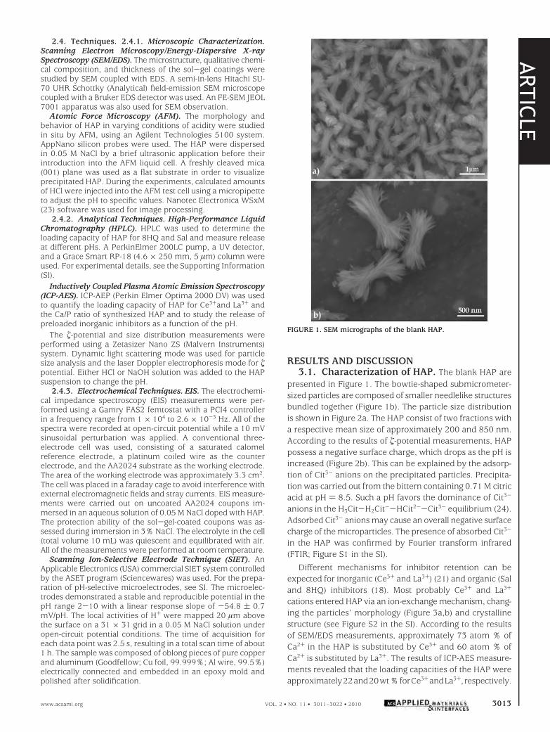
RESULTS AND DISCUSSION3.1. Characterization of HAP. The blank HAP are
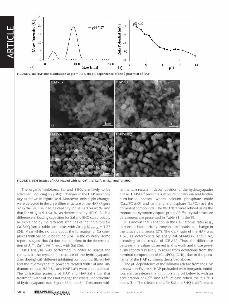
presented in Figure 1. The bowtie-shaped submicrometer-sized particles are composed of smaller needlelike structuresbundled together (Figure 1b). The particle size distributionis shown in Figure 2a. The HAP consist of two fractions witha respective mean size of approximately 200 and 850 nm.According to the results of -potential measurements, HAPpossess a negative surface charge, which drops as the pH isincreased (Figure 2b). This can be explained by the adsorp-tion of Cit3- anions on the precipitated particles. Precipita-tion was carried out from the bittern containing 0.71 M citricacid at pH ) 8.5. Such a pH favors the dominance of Cit3-
anions in the H3Cit-H2Cit--HCit2--Cit3- equilibrium (24).Adsorbed Cit3- anions may cause an overall negative surfacecharge of the microparticles. The presence of absorbed Cit3-
in the HAP was confirmed by Fourier transform infrared(FTIR; Figure S1 in the SI).
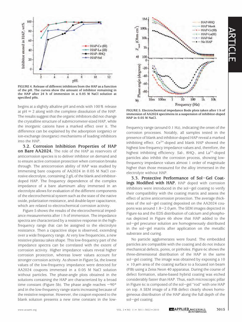
Different mechanisms for inhibitor retention can beexpected for inorganic (Ce3+ and La3+) (21) and organic (Saland 8HQ) inhibitors (18). Most probably Ce3+ and La3+
cations entered HAP via an ion-exchange mechanism, chang-ing the particles’ morphology (Figure 3a,b) and crystallinestructure (see Figure S2 in the SI). According to the resultsof SEM/EDS measurements, approximately 73 atom % ofCa2+ in the HAP is substituted by Ce3+ and 60 atom % ofCa2+ is substituted by La3+. The results of ICP-AES measure-ments revealed that the loading capacities of the HAP wereapproximately22and20wt%forCe3+andLa3+, respectively.
FIGURE 1. SEM micrographs of the blank HAP.
ARTIC
LE
www.acsami.org VOL. 2 • NO. 11 • 3011–3022 • 2010 3013
The organic inhibitors, Sal and 8HQ, are likely to beadsorbed, inducing only slight changes in the HAP morphol-ogy as shown in Figure 3c,d. Moreover, only slight changeswere detected in the crystalline structure of the HAP (FigureS2 in the SI). The loading capacity for Sal is 0.54 wt %, andthat for 8HQ is 9.3 wt %, as determined by HPLC. Such adifference in loading capacities for Sal and 8HQ can probablybe explained by the different affinities of the inhibitors forCa. 8HQ forms stable complexes with Ca: log KCa(8HQ)2
1 ) 3.27(24). Meanwhile, no data about the formation of Ca com-plexes with Sal could be found (25). To the contrary, somereports suggest that Ca does not interfere in the determina-tion of Al3+, Zn2+, Fe3+, etc., with Sal (26).
XRD analysis was performed in order to assess thechanges in the crystalline structure of the hydroxyapatiteafter doping with different inhibiting compounds. Blank HAPand the hydroxyapatite powders treated with Sal and lan-thanum nitrate (HAP-Sal and HAP-LaIII) were characterized.The diffraction patterns of HAP and HAP-Sal show thattreatment with Sal does not change the crystalline structureof hydroxyapatite (see Figure S2 in the SI). Treatment with
lanthanum results in decomposition of the hydroxyapatitephase. HAP-LaIII presents a mixture of calcium- and lantha-num-based phases, where calcium phosphate oxide[Ca10(PO4)6O] and lanthanum phosphate (LaPO4) are thedominant compounds. The XRD data were refined using themonoclinic symmetry (space group P21/b); crystal structureparameters are presented in Table S1 in the SI.
It is known that variation in the Ca/P atomic ratio (e.g.,in nonstoichiometric hydroxyapatites) leads to a change inthe lattice parameters (27). The Ca/P ratio of the HAP was1.57, as determined by analytical SEM/EDS, and 1.62,according to the results of ICP-AES. Thus, the differencebetween the values observed in this work and those previ-ously reported is likely to result from deviations from thenominal composition of [Ca5(PO4)3(OH)]2 due to the pecu-liarity of the HAP synthesis described above.
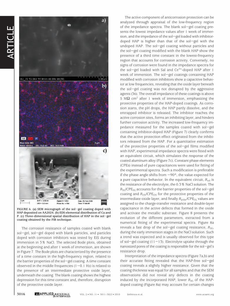
The pH dependence of the inhibitor release from the HAPis shown in Figure 4. HAP preloaded with inorganic inhibi-tors start to release the inhibitors at a pH below 6, with anacceleration of Ce3+ and La3+ release when the pH fallsbelow 3.1. The release trend for Sal and 8HQ is different: it
FIGURE 2. (a) HAP size distribution at pH ) 7.57. (b) pH dependence of the potential of HAP.
FIGURE 3. SEM images of HAP loaded with (a) Ce3+, (b) La3+, (c) Sal, and (d) 8HQ.
ARTIC
LE
3014 VOL. 2 • NO. 11 • 3011–3022 • 2010 Snihirova et al. www.acsami.org
begins at a slightly alkaline pH and ends with 100% releaseat pH ) 2 along with the complete dissolution of the HAP.The results suggest that the organic inhibitors did not changethe crystalline structure of submicrometer-sized HAP, whilethe inorganic cations have a marked effect over it. Thedifference can be explained by the adsorption (organic) orion-exchange (inorganic) mechanisms of loading inhibitorsinto the HAP.
3.2. Corrosion Inhibition Properties of HAPon Bare AA2024. The role of the HAP as reservoirs ofanticorrosion species is to deliver inhibitor on demand andto ensure active corrosion protection when corrosion breaksthrough. The anticorrosion ability of HAP was studied byimmersing bare coupons of AA2024 in 0.05 M NaCl cor-rosive electrolyte, containing 2 g/L of the blank and inhibitor-doped HAP. The frequency dependence of the compleximpedance of a bare aluminum alloy immersed in anelectrolyte allows for evaluation of the different componentsof the electrochemical system such as the state of the nativeoxide, polarization resistance, and double-layer capacitance,which are related to electrochemical corrosion activity.
Figure 5 shows the results of the electrochemical imped-ance measurements after 1 h of immersion. The impedancespectra are characterized by a resistive response in the high-frequency range that can be assigned to the electrolyteresistance. Then a capacitive slope is observed, extendingover a wide frequency range. At very low frequencies, a newresistive plateau takes shape. This low-frequency part of theimpedance spectra can be correlated with the extent ofcorrosion activity. Higher impedance values reveal highercorrosion protection, whereas lower values account forstronger corrosion activity. As shown in Figure 5a, the lowestvalues of the low-frequency impedance were detected forAA2024 coupons immersed in a 0.05 M NaCl solutionwithout particles. The phase-angle plots obtained in thesolutions containing the HAP are characterized by a broadtime constant (Figure 5b). The phase angle reaches -90°and in the low-frequency range starts increasing because ofthe resistive response. However, the coupon exposed to theblank solution presents a new time constant in the low-
frequency range (around 0.1 Hz), indicating the onset of thecorrosion processes. Notably, all samples tested in thepresence of blank and inhibitor-doped HAP reveal a markedinhibiting effect. Ce3+-doped and blank HAP showed thehighest low-frequency impedance values and, therefore, thehighest inhibiting efficiency. Sal-, 8HQ-, and La3+-dopedparticles also inhibit the corrosion process, showing low-frequency impedance values almost 1 order of magnitudehigher than those measured for the alloy immersed in theelectrolyte without HAP.
3.3. Protective Performance of Sol-Gel Coat-ings Modified with HAP. HAP doped with corrosioninhibitors were introduced in the sol-gel coating to verifytheir compatibility with the coating matrix and assess theeffect of active anticorrosion protection. The average thick-ness of the sol-gel coating deposited on the AA2024 cou-pons was around 1.8-2.0 µm. The SEM images depicted inFigure 6a and the EDS distribution of calcium and phospho-rus depicted in Figure 6b show that HAP added to thesol-gel precursor solution are homogeneously distributedin the sol-gel matrix after application on the metallicsubstrate and curing.
No particle agglomerates were found. The embeddedparticles are compatible with the coating and do not inducemechanical defects, pores, or pinholes. Figure 6c shows thethree-dimensional distribution of the HAP in the samesol-gel coating. The image was obtained by exposing a 10× 10 µm area of the coating surface to a focused ion beam(FIB) using a Zeiss Neon 40 apparatus. During the course ofdefect formation, silane-based hybrid coating was etchedconsiderably faster than HAP. Thus, each microscopic pillarin Figure 6c is composed of the sol-gel “rod” with one HAPon top. A SEM image of a FIB defect clearly shows homo-geneous distribution of the HAP along the full depth of thesol-gel coating.
FIGURE 4. Release of different inhibitors from the HAP as a functionof the pH. The curves show the amount of inhibitor remaining inthe HAP after 24 h of immersion in a 0.05 M NaCl solution atspecified pHs.
FIGURE 5. Electrochemical impedance Bode plots taken after 1 h ofimmersion of AA2024 specimens in a suspension of inhibitor-dopedHAP in 0.05 M NaCl.
ARTIC
LE
www.acsami.org VOL. 2 • NO. 11 • 3011–3022 • 2010 3015
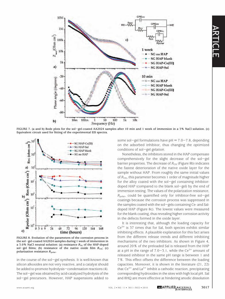
The corrosion resistance of samples coated with blanksol-gel, sol-gel doped with blank particles, and particlesdoped with corrosion inhibitors was tested by EIS duringimmersion in 3% NaCl. The selected Bode plots, obtainedat the beginning and after 1 week of immersion, are shownin Figure 7. The Bode plots are characterized by the presenceof a time constant in the high-frequency region, related tothe barrier properties of the sol-gel coating. A time constantobserved in the middle frequencies (1-0.1 Hz) is related tothe presence of an intermediate protective oxide layer,underneath the coating. The blank coating shows the highestdepression for this time constant and, therefore, disruptionof the protective oxide layer.
The active component of anticorrosion protection can beanalyzed through appraisal of the low-frequency regionof the impedance spectra. The blank sol-gel coating pre-sents the lowest impedance values after 1 week of immer-sion, and the impedance of the sol-gel loaded with inhibitor-doped HAP is higher than that of the sol-gel with theundoped HAP. The sol-gel coating without particles andthe sol-gel coating modified with the blank HAP show thepresence of a third time constant in the lowest-frequencyregion that accounts for corrosion activity. Conversely, nosigns of corrosion were found in the impedance spectra forthe sol-gel loaded with Sal and Ce3+-doped HAP after 1week of immersion. The sol-gel coatings containing HAPmodified with corrosion inhibitors show a capacitive behav-ior at low frequencies, revealing that the oxide layer beneaththe sol-gel coating was not disrupted by the aggressiveagents (36). The overall impedance of these coatings is above5 MΩ cm2 after 1 week of immersion, emphasizing theprotective properties of the HAP-doped coatings. As corro-sion starts, the pH drops, the HAP partly dissolve, and theentrapped inhibitor is released. The inhibitor reaches theactive corrosion sites, forms an inhibiting layer, and hindersfurther corrosion activity. The increased low-frequency im-pedance measured for the samples coated with sol-gelcontaining inhibitor-doped HAP (Figure 7) clearly confirmsthat the active protection effect originated from the inhibi-tors released from the HAP. For a quantitative estimationof the protective properties of the sol-gel films modifiedwith HAP, experimental impedance spectra were fitted withan equivalent circuit, which simulates the response of thecoated aluminum alloy (Figure 7c). Constant phase elements(CPEs) instead of pure capacitances were used for fitting ofthe experimental spectra. Such a modification is preferableif the phase angle shifts from -90°, the value expected fora pure capacitive behavior. In the equivalent circuit, Rsol isthe resistance of the electrolyte, the 0.3% NaCl solution. TheRSG/CPESG accounts for the barrier properties of the sol-gelcoating and ROX/CPEOX for the protective properties of theintermediate oxide layer, and finally Rpolar/CPEDL values areassigned to the charge-transfer resistance and double-layercapacitance in the active defects that formed in the oxideand activate the metallic substrate. Figure 8 presents theevolution of the different parameters, extracted from anumerical fitting of the experimental spectra. Figure 8areveals a fast drop of the sol-gel coating resistance, RSG,during the early immersion stages in the NaCl solution. Sucha trend was expected and is usually observed for this typeof sol-gel coating (11-13). Electrolyte uptake through thenanosized pores of the coating is responsible for the sol-gel’sresistance drop.
Interpretation of the impedance spectra (Figure 7a,b) andtheir accurate fitting revealed that the HAP-free sol-gelcoating reveals a slightly higher resistance. Given that thecoating thickness was equal for all samples and that the SEMobservations did not reveal any defects in the coatinginduced by the incorporated HAP, lower RSG of the HAP-doped coating (Figure 8a) may account for certain changes
FIGURE 6. (a) SEM micrograph of the sol-gel coating doped withHAP deposited on AA2024. (b) EDS elemental distribution of Ca andP. (c) Three-dimensional spatial distribution of HAP in the sol-gelcoating obtained by the FIB technique.
ARTIC
LE
3016 VOL. 2 • NO. 11 • 3011–3022 • 2010 Snihirova et al. www.acsami.org
in the course of the sol-gel synthesis. It is well-known thatsilicon alkoxides are not very reactive, and a catalyst shouldbe added to promote hydrolysis-condensation reactions (4).The sol-gel was obtained by acid-catalyzed hydrolysis of thesol-gel precursors. However, HAP suspensions added to
some sol-gel formulations have pH ) 7.0-7.8, dependingon the adsorbed inhibitor, thus changing the optimizedconditions of sol-gel gelation.
Nonetheless, the inhibitors stored in the HAP compensatecomprehensively for the slight decrease of the sol-gelbarrier properties. The decrease of ROX (Figure 8b) indicatesthe fastest deterioration of the native oxide layer for thesample without HAP. From roughly the same initial valuesof ROX, this parameter becomes 1 order of magnitude higherfor the alloy coated with the sol-gel containing inhibitor-doped HAP (compared to the blank sol-gel) by the end ofimmersion testing. The values of the polarization resistance,Rpolar, could be quantified only for inhibitor-free sol-gelcoatings because the corrosion process was suppressed inthe samples coated with the sol-gels containing Ce- and Sal-doped HAP (Figure 8c). The lowest values were measuredfor the blank coating, thus revealing higher corrosion activityin the defects formed in the oxide layer.
It is interesting that, although the loading capacity forCe3+ is 37 times that for Sal, both species exhibit similarinhibiting effects. A plausible explanation for this fact arisesfrom the different release trends and different inhibitingmechanisms of the two inhibitors. As shown in Figure 4,around 20% of the preloaded Sal is released from the HAPat a pH in the range of 7.0-3.1, while the Ce3+ amount ofreleased inhibitor in the same pH range is between 1 and7%. This effect offsets the difference between the loadingcapacities. Moreover, it is shown in the literature (21, 22)that Ce3+ and La3+ inhibit a cathodic reaction, precipitatingcorresponding hydroxides in the sites with high local pH. Saland 8HQ are more effective at hindering anodic dissolution
FIGURE 7. (a and b) Bode plots for the sol-gel-coated AA2024 samples after 10 min and 1 week of immersion in a 3% NaCl solution. (c)Equivalent circuit used for fitting of the experimental EIS spectra.
FIGURE 8. Evolution of the parameters of the corrosion process inthe sol-gel-coated AA2024 samples during 1 week of immersion ina 3.0% NaCl neutral solution: (a) resistance RSG of the HAP-dopedsol-gel films; (b) resistance of the native oxide film ROX; (c)polarization resistance Rpolar.
ARTIC
LE
www.acsami.org VOL. 2 • NO. 11 • 3011–3022 • 2010 3017
because they form insoluble chelates with Al3+. Given thatcathodic and anodic reactions are usually separated by amicrodistance and Ce3+ cations are released in anodicallyactive sites, it is logical to assume that a higher amount ofdissolved Ce3+ is necessary to reach the cathodic sitescompared to Sal.
The AA2024 sample coated with the blank sol-gel showsthe highest rate of degradation, while specimens coveredwith the sol-gel doped with inhibitor-loaded HAP demon-strate better corrosion protection. Thus, the inhibitor incor-porated into the particles keeps its activity and does notdisturb the integrity of the sol-gel matrix when released.The results illustrate that the inhibitor-doped HAP can beused as active, pH-sensitive reservoirs for corrosion inhibitors.
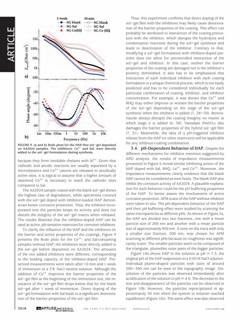
To clarify the influence of the HAP and the inhibitors onthe barrier and active properties of the coatings, Figure 9presents the Bode plots for the Ce3+- and Sal-containingsamples without HAP; the inhibitors were directly added tothe sol-gel before deposition on AA2024. The amountsof the two added inhibitors were different, correspondingto the loading capacity of the inhibitor-doped HAP. Pre-sented measurements were taken after 10 min and 1 weekof immersion in a 3% NaCl neutral solution. Although theaddition of Ce3+ improves the barrier properties of thesol-gel film at the beginning of the immersion test, the re-sistance of the sol-gel film drops below that for the blanksol-gel after 1 week of immersion. Direct doping of thesol-gel formulation with Sal leads to a significant deteriora-tion of the barrier properties of the sol-gel film.
Thus, this experiment confirms that direct doping of thesol-gel film with the inhibitors may likely cause deteriora-tion of the barrier properties of the coating. This effect canprobably be attributed to interaction of the coating precur-sors with the inhibitor, which disrupts the hydrolysis andcondensation reactions during the sol-gel synthesis andleads to deactivation of the inhibitor. Contrary to that,modifying a sol-gel formulation with inhibitor-doped par-ticles does not allow for uncontrolled interaction of thesol-gel and inhibitor. In this case, neither the barrierproperties of the coating are damaged nor is the inhibitor’spotency diminished. It also has to be emphasized thatinteraction of each individual inhibitor with each coatingformulation is a unique chemical process, which is not easilypredicted and has to be considered individually for eachparticular combination of coating, inhibitor, and inhibitorconcentration. For example, it was shown that Ce3+ and8HQ may either improve or worsen the barrier propertiesof the sol-gel depending on the stage of the sol-gelsynthesis when the inhibitor is added (7, 28-30). Benzot-riazole always disrupts the coating integrity no matter atwhich stage it is added (6, 30). Vanadate (NaVO3) alsodamages the barrier properties of the hybrid sol-gel film(7, 31). Meanwhile, the idea of a pH-triggered inhibitorrelease from the HAP (or other reservoirs) will be applicablefor any inhibitor-coating combination.
3.4. pH-Dependent Behavior of HAP. Despite thedifferent mechanisms for inhibitor retention suggested byXRD analysis, the results of impedance measurementspresented in Figure 5 reveal similar inhibiting action of theHAP doped with Sal, 8HQ, La3+, and Ce3+. Moreover, theimpedance measurements clearly evidence that the blankHAP cannot be considered as inert hosts. The blank HAP alsoinhibit the corrosion activity of AA2024. A plausible explana-tion for such behavior could be the pH buffering propertiesof the HAP. To better assess the mechanisms of activecorrosion protection, AFM scans of the HAP without inhibitorwere taken in situ. The pH-dependent behavior of the HAPand their pH buffering effect were studied by scanning thesame microparticles at different pHs. As shown in Figure 2a,the HAP are divided into two fractions, one with a meanparticle size of 200 nm and another with a mean particlesize of approximately 850 nm. A zone on the mica with onlya smaller size fraction, 200 nm, was chosen for AFMscanning at different pHs because its roughness was signifi-cantly lower. The smaller particles seem to be composed ofthe triangular, plumelike outer parts of the bigger particles.
Figure 10a shows HAP in the solution at pH ) 7.5, theoriginal pH of the HAP suspension in a 0.05 M NaCl solution.Individual plume-shaped particles with sizes of around200-300 nm can be seen in the topography image. Dis-solution of the particles was observed immediately afteracidification of the solution to pH ) 4.0. The decrease in thesize and disappearance of the particles can be observed inFigure 10b. However, the particles reprecipitated in ap-proximately 50 min when the system in solution reachedequilibrium (Figure 10c). The same effect was also observed
FIGURE 9. (a and b) Bode plots for the HAP-free sol-gel depositedon AA2024 samples. The inhibitors, Ce3+ and Sal, were directlyadded to the sol-gel formulation during synthesis.
ARTIC
LE
3018 VOL. 2 • NO. 11 • 3011–3022 • 2010 Snihirova et al. www.acsami.org
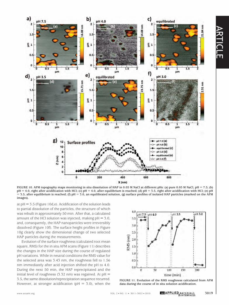
at pH ) 3.5 (Figure 10d,e). Acidification of the solution leadsto partial dissolution of the particles, the structure of whichwas rebuilt in approximately 50 min. After that, a calculatedamount of the HCl solution was injected, making pH ) 3.0,and, consequently, the HAP nanoparticles were irreversiblydissolved (Figure 10f). The surface height profiles in Figure10g clearly show the dimensional change of two selectedHAP particles during the measurements.
Evolution of the surface roughness (calculated root meansquare, RMS) for the in situ AFM scans (Figure 11) describesthe changes in the HAP size during the course of regulatedpH variations. While in neutral conditions the RMS value forthe selected area was 3.43 nm, the roughness fell to 1.56nm immediately after acid injection shifted the pH to 4.0.During the next 50 min, the HAP reprecipitated and theinitial level of roughness (3.32 nm) was regained. At pH )3.5, the same dissolution/reprecipitation sequence recurred.However, at stronger acidification (pH ) 3.0), when the
FIGURE 10. AFM topography maps monitoring in situ dissolution of HAP in 0.05 M NaCl at different pHs: (a) pure 0.05 M NaCl, pH ) 7.5; (b)pH ) 4.0, right after acidification with HCl; (c) pH ) 4.0, after equilibrium is reached; (d) pH ) 3.5, right after acidification with HCl; (e) pH) 3.5, after equilibrium is reached; (f) pH ) 3.0, an equilibrated solution, (g) surface profiles of isolated HAP particles (marked on the AFMimages).
FIGURE 11. Evolution of the RMS roughness calculated from AFMdata during the course of in situ solution acidification.
ARTIC
LE
www.acsami.org VOL. 2 • NO. 11 • 3011–3022 • 2010 3019
buffering capacity of HAP was exceeded, the RMS roughnessdecreased to around 0.2 nm; corresponding to the charac-teristic roughness of smooth mica (001). Thus, reversibledissolution of HAP was observed in the pH range between4.0 and 3.0.
As reported earlier (19), the nucleation and growthprocess of the HAP strongly depends on the initial pH. HAPdissolve at acidic pH. The modeling of ionic equilibria relativeto Ca2+ (see Figure S3 in the SI) predict the initiation of HAPdissolution at pH ) 8 that is in good agreement with therelease trend of organic inhibitors (Figure 4). The totalabsence of solid products according to ionic equilibria ispredicted for pH lower than 4. Obviously, dissolved phos-phate-containing particles are liable to shift the pH back toneutral values, causing particle reprecipitation. Such behav-ior of the particles can be explained by their buffering effectoriginating from PO4
3--HPO42--H2PO4
--H3PO4 and Cit3--HCit2--H2Cit--H3Cit equilibria existing in a solution of HAP.The results highlight that HAP are sensitive to pH changesin the acidic range, making them suitable hosts to storecorrosion inhibitors to protect aluminum substrates asdiscussed below.
3.5. pH of the Anodic Dissolution of Aluminum:Modeling and Experimental Measurements. To beused as effective inhibitor reservoirs, HAP have to fulfillseveral requirements. One of them is the ability to store theinhibitor and release it when the local pH decreases. In spiteof the generally accepted idea that anodic dissolution of Alis accompanied by local acidification, the literature provideslittle confirmation with experimental data. There are veryfew works (32-34) reporting local pH values of anodicdissolution during the course of corrosion of aluminumalloys. Remarkably, in all three mentioned articles, themeasured pH in the anodic sites corresponded to thesensitivity limit of the chosen experimental method. In thiswork, we measured the local pH of anodic dissolution of Alusing pH-selective microelectrodes possessing sensitivityextended into the acidic region.
The anodic dissolution of Al leads to the formation ofhydrated Al3+ and its hydroxy complexes. A simple calcula-tion shows that the pH values of 0.1, 0.01, 0.001, and 0.0001M aqueous solutions of Al3+ are 2.99, 3.49, 4.01, and 4.56,respectively, due to hydrolysis (eq 1). Kst
1 was taken from ref24.
Thus, if the anodic dissolution of Al and reactions ofcathodic reduction are separated, the pH at purely anodicsites can fall as low as 3.0-3.5, depending on the intensityof the dissolution and the conditions of ionic diffusion.
It is generally accepted that pitting corrosion of AA2024begins in the intermetallic inclusions, the so-called S phase,which cover almost 3% of the geometrical surface area ofthe alloy. These intermetallic zones are composed of
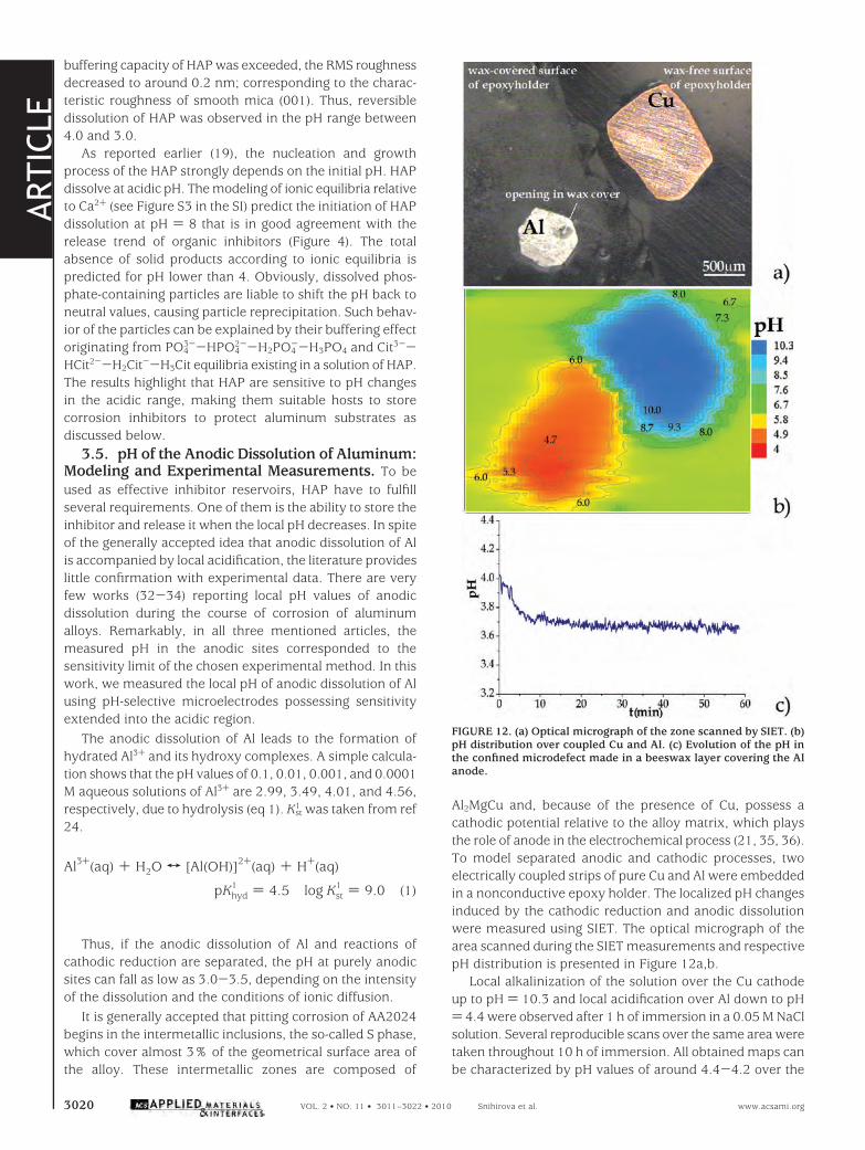
Al2MgCu and, because of the presence of Cu, possess acathodic potential relative to the alloy matrix, which playsthe role of anode in the electrochemical process (21, 35, 36).To model separated anodic and cathodic processes, twoelectrically coupled strips of pure Cu and Al were embeddedin a nonconductive epoxy holder. The localized pH changesinduced by the cathodic reduction and anodic dissolutionwere measured using SIET. The optical micrograph of thearea scanned during the SIET measurements and respectivepH distribution is presented in Figure 12a,b.
Local alkalinization of the solution over the Cu cathodeup to pH ) 10.3 and local acidification over Al down to pH) 4.4 were observed after 1 h of immersion in a 0.05 M NaClsolution. Several reproducible scans over the same area weretaken throughout 10 h of immersion. All obtained maps canbe characterized by pH values of around 4.4-4.2 over the
Al3+(aq) + H2O T [Al(OH)]2+(aq) + H+(aq)
pKhyd1 ) 4.5 log Kst
1 ) 9.0 (1)
FIGURE 12. (a) Optical micrograph of the zone scanned by SIET. (b)pH distribution over coupled Cu and Al. (c) Evolution of the pH inthe confined microdefect made in a beeswax layer covering the Alanode.
ARTIC
LE
3020 VOL. 2 • NO. 11 • 3011–3022 • 2010 Snihirova et al. www.acsami.org
anodic zone, which are, however, higher than those ex-pected, taking into account intensive dissolution of Al.
To augment the anodic dissolution and impede the dif-fusion of generated Al3+ and H+ species, the area of theanode was made even smaller. The polished surface of theAl strip was coated with a thin layer of beeswax and a defectof approximately 250 × 150 µm was made in the beeswaxlayer to expose a small part of the Al surface. The localizedpH was then measured in one single point, inside thisconfined microdefect. The time-dependent curve of mea-sured pH is presented in Figure 12c. A decrease of the pHdown to 3.65 was monitored during the course of Aldissolution.
The results of in situ AFM, release measurements, andlocal pH monitoring suggest that the HAP are pH-sensitivein the pH range 4-3 corresponding to the local pH of theanodic dissolution of Al. Thus, HAP fulfill the requirementof pH sensitivity and can be used as reservoirs for the storageand controlled release of the corrosion inhibitor. This mech-anism is, therefore, responsible for the improved corrosionprotection observed in the EIS spectra. Assuming that cor-rosion occurs in localized defects formed in the oxide layer,underneath the coating, the local pH at the anodes decreasesto values that induce partial dissolution of the particles,which, in turn, release part of the inhibitor. The inhibitorforms a protective layer, and the active site is healed.Because the local corrosion activity is hindered, the pHincreases again, stopping the particle dissolution and inhibi-tor release. This can be considered an active anticorrosionsystem for the protection of aluminum alloys.
CONCLUSIONSThe citrate-modified, calcium-deficient HAP were syn-
thesized to act as submicrometer reservoirs for the corrosioninhibitor.
The results of particle characterization confirm that HAPmeet the requirements for inhibitor reservoirs. These includethe following: chemical stability and compatibility with thehybrid sol-gel matrix, sufficient loading capacity, ability tosense the corrosion onset (local acidification), and subse-quent release of the inhibitor on demand.
HAP provide an anticorrosion effect owing to a two-component protective mechanism: release of the inhibitorand pH buffering resulting from microparticle dissolution.The sensitivity of the HAP to pH is predetermined by theirsolubility at acidic pH. Local acidification down to pH ) 3.65occurs as a consequence of the anodic dissolution of Al, asshown with localized pH measurements.
The corrosion inhibitors are released during dissolutionof the microparticles. The inhibiting effect of both blank andinhibitor-loaded HAP was successfully confirmed on bareand sol-gel-coated 2024 alloys. In both cases, the inhibitor-loaded particles delayed or suppressed the corrosion activity.The blank microparticles demonstrated a certain inhibitingeffect that could be ascribed to their pH buffering properties.Thus, ecobenign and easy to produce citrate-modified HAPare proven to be effective anticorrosive agents.
Acknowledgment. We acknowledge financial supportfrom Projects REDE/1509/RME/2005, PTDC/CTM/65632/2006, and PTDC/CTM/108446/2008 (FCT, Portugal) andEuropean FP7 “MUST” NMP3-LA-2008-214261. S.K. thanksFCT for his postdoctoral grant. C. Santos from the Universityof Aveiro (Aveiro, Portugal) is acknowledged for preparationof the HAP. Prof. G. Grundmeier and Dr. W. Wijting fromthe University of Paderborn (Paderborn, Germany) areacknowledged for providing the samples with defects madeby FIB. Dr. A. S. L. Castela from Instituto Politecnico deSetubal (Setubal, Portugal) is acknowledged for his help withHPLC analysis.
Supporting Information Available: Experimental detailsof HPLC measurements, preparation of pH-selective micro-electrodes, experimental, results and discussion of FTIR andXRD characterization of HAP, and modeling of ionic equi-libria in a HAP solution. This material is available free ofcharge via the Internet at http://pubs.acs.org.
REFERENCES AND NOTES(1) Wang, D.; Bierwagen, G. P. Prog. Org. Coat. 2009, 64, 327–338.(2) Metroke, T. L.; Parkhill, R. L.; Knobbe, E. T. Prog. Org. Coat. 2001,
41, 233–238.(3) Guglielmi, M. J. Sol-Gel Sci. Technol. 1997, 8, 443–449.(4) Zheludkevich, M. L.; Ferreira, M. G. S.; Miranda Salvado, I. M. J.
Mater. Chem. 2005, 48, 5099–5111.(5) Khramov, A. N.; Voevodin, N. N.; Balbyshev, V. N.; Donley, M. S.
Thin Solid Films 2004, 447, 549–557.(6) Shchukin, D. G.; Zheludkevich, M. L.; Yasakau, K. A.; Lamaka,
S. V.; Ferreira, M. G. S.; Mohwald, H. Adv. Mater. 2006, 18, 1672–1678.
(7) Yasakau, K. A.; Zheludkevich, M. L.; Lamaka, S. V.; Ferreira,M. G. S. Proceedings of the 17th International Corrosion Congress,Las Vegas, NV, Oct 6-10, 2008, p 2720; NACE: Houston, TX,2008.
(8) Khramov, A. N.; Voevodin, N. N.; Balbyshev, V. N.; Mantz, R. A.Thin Solid Films 2005, 483, 191–196.
(9) Shchukin, D. G.; Grigoriev, D. O.; Mohwald, H. Soft Matter 2010,6, 720–725.
(10) Shchukin, D. G.; Mohwald, H. Adv. Funct. Mater. 2007, 17, 1451–1458.
(11) Lamaka, S. V.; Zheludkevich, M. L.; Yasakau, K. A.; Serra, R.;Poznyak, S. K.; Ferreira, M. G. S. Prog. Org. Coat. 2007, 58, 127–135.
(12) Lamaka, S. V.; Zheludkevich, M. L.; Yasakau, K. A.; Montemor,M. F.; Cecılio, P.; Ferreira, M. G. S. Electrochem. Commun. 2006,8, 421–428.
(13) Shchukin, D. G.; Lamaka, S. V.; Yasakau, K. A.; Zheludkevich,M. L.; Mohwald, H.; Ferreira, M. G. S. J. Phys. Chem. C 2008, 112,958–964.
(14) Poznyak, S. K.; Tedim, J.; Rodrigues, L. M.; Salak, A. N.; Zhelud-kevich, M. L.; Dick, L. F. P.; Ferreira, M. G. S. ACS Appl. Mater.Interfaces 2009, 1, 2353–2362.
(15) Decher, G.; Hong, J. D.; Schmitt, J. Thin Solid Films 1992, 210/211, 831–835.
(16) Lamaka, S. V.; Shchukin, D. G.; Andreeva, D. V.; Zheludkevich,M. L.; Mohwald, H.; Ferreira, M. G. S. Adv. Funct. Mater. 2008,18, 3137–3147.
(17) Hiromoto, S.; Yamamoto, A. Electrochim. Acta 2009, 54, 7085–7093.
(18) Bastidas, D. M.; La Iglesia, V. M.; Criado, M.; Fajardo, S.; La Iglesia,A.; Bastidas, J. M. Constr. Build. Mater. 2010, 24, 2646–2649.
(19) Martins, M. A.; Santos, C.; Almeida, M. M.; Costa, M. E. V. J. ColloidInterface Sci. 2008, 318, 210–216.
(20) Santos, C.; Martins, M.; Almeida, M. M.; Costa, M. E. V. Microsc.Microanal. 2009, 15, 85–86.
(21) Yasakau, K. A.; Zheludkevich, M. L.; Lamaka, S. V.; Ferreira,M. G. S. J. Phys. Chem. B 2006, 110, 5515–5528.
(22) Lamaka, S. V.; Zheludkevich, M. L.; Yasakau, K. A.; Montemor,M. F.; Ferreira, M. G. S. Electrochim. Acta 2007, 52, 7231–7247.
ARTIC
LE
www.acsami.org VOL. 2 • NO. 11 • 3011–3022 • 2010 3021
(23) Horcas, I.; Fernandez, R.; Gomez-Rodriguez, J. M.; Colchero, J.;Gomez-Herrero, J.; Baro, A. M. Rev. Sci. Instrum. 2007, 78,013705.
(24) Lur’e, Y. Y. Handbook of Analytical Chemistry, 6th ed.; Himiya,1989.
(25) In Stability constants of metal-ion complexes, part B: organicligands; Perrin, D., Ed.; Pergamon Press: Oxford, U.K., 1979.
(26) Sarkar, M. Analyst 1991, 116, 537–541.(27) Wilson, R. M.; Elliot, J. C.; Dowker, S. E. P. J. Solid State Chem.
2003, 174, 132–140.(28) Zheludkevich, M. L.; Serra, R.; Montemor, M. F.; Yasakau, K. A.;
Miranda Salvado, I. M.; Ferreira, M. G. S. Electrochim. Acta 2005,51, 208–217.
(29) Galio, A. F.; Lamaka, S. V.; Zheludkevich, M. L.; Dick, L. F.; Muller,I. L.; Ferreira, M. G. S. Surf. Coat. Technol. 2010, 204, 1479–1486.
(30) Yasakau, K.; Zheludkevich, M.; Karavai, O. V.; Ferreira, M. G. S.
Prog. Org. Coat. 2008, 63, 352–361.(31) Voevodin, N. N.; Grebasch, N. T.; Soto, W. S.; Arnold, F. E.;
Donley, M. S. Surf. Coat. Technol. 2001, 140, 24–28.(32) Ding, H.; Hawthorn, G. A.; Hihara, L. H. J. Electrochem. Soc. 2009,
156, C352–C359.(33) Isaacs, H. S.; Adzic, G.; Jeffcoate, C. S. Corrosion 2000, 56, 971–
978.(34) Lamaka, S. V.; Taryba, M. G.; Zheludkevich, M. L.; Ferreira,
M. G. S. Electroanalysis 2009, 21, 2447–2453.(35) Liu, Z.; Chong, P. H.; Butt, A. N.; Skeldon, P.; Thompson, G. E.
Appl. Surf. Sci. 2005, 247, 294–299.(36) Buchheit, R. G.; Grant, R. P.; Hlava, P. F.; McKenzie, B.; Zender,
G. L. J. Electrochem. Soc. 1997, 144, 2621–2628.
AM1005942
ARTIC
LE
3022 VOL. 2 • NO. 11 • 3011–3022 • 2010 Snihirova et al. www.acsami.org
1
Hydroxyapatite microparticles as feed-back active
reservoirs of corrosion inhibitors
D. Snihirova1, S. V. Lamaka1*, M. Taryba1, A. N. Salak2, S. Kallip2, M. L. Zheludkevich2,
M.G.S. Ferreira1,2, M.F.Montemor1
1 ICEMS, Instituto Superior Tecnico, UTL, Av. Rovisco Pais, 1049-001 Lisbon, Portugal 2 CICECO, Dep.Ceramics and Glass Eng., University of Aveiro, 3810-193, Aveiro, Portugal
Supporting information
HPLC. High performance liquid chromatography was used to determine the loading capacity of
HAP for 8-HQ and Sal and measure release at different pH. A PerkinElmer 200LC pump, an UV-
detector and Grace Smart RP-18 (4.6×250mm, 5µm) column were used. 20µl of the sample was
injected into the column using a sample loop. The chromatographic conditions for determination of
8-hydroxyquinoline were optimized as follows: acetonitrile-water (65:35 v/v) pH = 3.05 was used
as a mobile phase; flow rate was 0.8ml/min; UV signal was recorded at 240nm; retention time was
4.23 min. The optimized chromatographic conditions for salicylaldoxime quantification: mobile
phase was a mixture of methanol-water-5% phosphoric acid (40:60:4 v/v); flow rate was 1.1ml/min;
UV detection was carried out at 301nm, retention time was 8.14min. TotalChrom 6.3 software was
used for data processing.
Preparation of pH-selective microelectrodes. The pH selective microelectrodes were prepared
from single-barreled, standard-wall (330 micron) borosilicate glass capillaries with an outer-
diameter of 1.5 mm. A P-97 Flaming/Brown Micropipette Puller (Sutter Instruments) was used to
shape the cone tip. The diameter of the apex of the tip was 2.0 ± 0.5 µm. Before use, the inner
surface of the capillaries was silanized by injecting 200 L of N,N-dimethyltrimethylsilylamine in a
glass preparation chamber at 200°C. The silanized microelectrodes were back-filled with the inner
filling solution and tip-filled with a selective ionophore-based oil-like membrane. The ion-selective
membrane was composed of 6 wt% 4-nonadecylpyridine, 12 mol% potassium tetrakis(4-
chlorophenyl)borate and membrane solvent 2-nitrophenyloctyl ether. All reagents for the pH-
2
selective membrane were Selectophore grade products from Fluka. The column length of the
membrane was about 60 - 70 m. A chlorinated silver wire was inserted into the inner filling
solution as the internal reference electrode. The inner filling solution contained a buffer solution
composed of 0.01M KH2PO4 and 0.1M KCl. The microelectrodes were calibrated using
commercially available (Fluka) pH buffers. A homemade Ag/AgCl/0.1M KCl, 0.01M KH2PO4
electrode with an inner solution stabilized by 3% agar-agar was used as external reference
electrode. The microelectrodes demonstrated a stable and reproducible potential in the pH range 2
to 10 with a linear response slope of -54.8 ± 0.7 mV/pH.
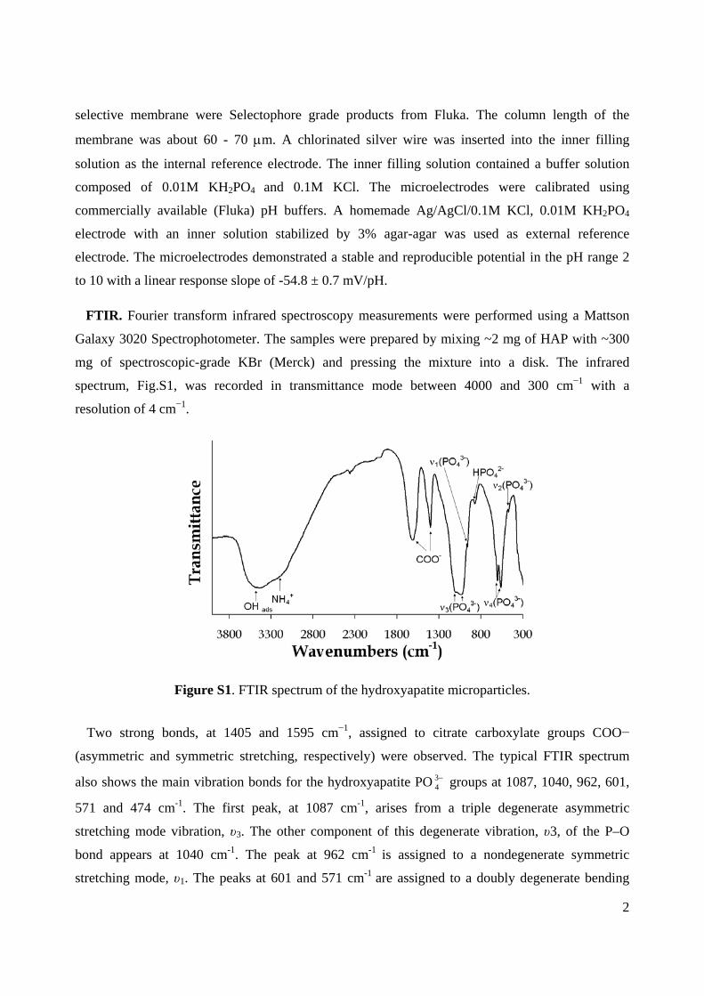
FTIR. Fourier transform infrared spectroscopy measurements were performed using a Mattson
Galaxy 3020 Spectrophotometer. The samples were prepared by mixing ~2 mg of HAP with ~300
mg of spectroscopic-grade KBr (Merck) and pressing the mixture into a disk. The infrared
spectrum, Fig.S1, was recorded in transmittance mode between 4000 and 300 cm−1 with a
resolution of 4 cm−1.
Figure S1. FTIR spectrum of the hydroxyapatite microparticles.
Two strong bonds, at 1405 and 1595 cm−1, assigned to citrate carboxylate groups COO−
(asymmetric and symmetric stretching, respectively) were observed. The typical FTIR spectrum
also shows the main vibration bonds for the hydroxyapatite PO 34 groups at 1087, 1040, 962, 601,
571 and 474 cm-1. The first peak, at 1087 cm-1, arises from a triple degenerate asymmetric
stretching mode vibration, υ3. The other component of this degenerate vibration, υ3, of the P–O
bond appears at 1040 cm-1. The peak at 962 cm-1 is assigned to a nondegenerate symmetric
stretching mode, υ1. The peaks at 601 and 571 cm-1 are assigned to a doubly degenerate bending
3
mode, υ4, of the O–P–O bond. The weak peak at 474 cm-1 is a component of the degenerate bending
mode, υ2. The broad band at 3400 cm-1 can be assigned to adsorbed water molecules. In addition, a
broad band detected at 3200 cm−1 accounts for the presence of ammonium ions, NH4+ [1S-3S].
XRD. Phase analysis of the precipitated powders of hydroxyapatite and hydroxyapatite-derived
compositions was performed by X-ray diffraction using a Rigaku D/MAX-B diffractometer (Cu Kα
radiation, tube power 40 kV, 30 mA; graphite monochromator, receiving slit of 0.15 mm). The
XRD data was collected over an angular range of 10<2θ<80º with 0.02º steps and exposition of 5
s/step. For the crystal structure characterization, the detailed data was recorded using a Philips
X’Pert MPD diffractometer (Ni-filtered Cu Kα radiation, tube power 40 kV, 50 mA; X’celerator
detector, and the exposition corresponded to 14 s per step of 0.02º over the same 2θ range) at room-
temperature. The obtained data was refined by the Rietveld method using the FULLPROF suite
[4S].
XRD analysis was performed in order to assess the changes in the crystalline structure of the
hydroxyapatite after doping with the different inhibiting compounds. Blank HAP, as well as the
hydroxyapatite powders treated with salicylaldoxime and lanthanum nitrate (HAP-Sal and HAP-
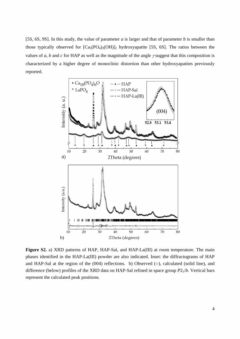
La(III)) were characterized. The diffraction patterns of HAP and HAP-Sal show that the treatment
with salicylaldoxime does not change the crystalline structure of hydroxyapatite, Fig. S2a. At the
same time, small shifts in the diffraction peaks were observed suggesting differences in the values
of the lattice parameters (see inset in Fig. S2a). Treatment with lanthanum results in decomposition
of the hydroxyapatite phase. HAP-La(III) presents a mixture of calcium- and lanthanum-based
phases, where calcium phosphate oxide Ca10(PO4)6O and lanthanum phosphate LaPO4 are the
dominant compounds (Fig. S2a).
The characteristic reflections in the XRD patterns of both HAP and HAP-Sal are indicative of the
monoclinic symmetry [5S, 6S]. Indeed, the crystal structure of these compositions was successfully
refined using the monoclinic P21/b space group. Fig. S2b shows the results of the refinement in the
case of HAP-Sal. The obtained values of the structure parameters are listed in Table S1. An attempt
to refine the XRD data using the hexagonal P63/m space group was made, as this symmetry was
previously attributed to the [Ca5(PO4)3(OH)]2 hydroxyapatite [7S] and to other related
hydroxyapatites with a Ca/P molar ratio different from 5:3 [8S]. However, the monoclinic
symmetry (space group P21/b) provided a better fit in respect to both the description of the
diffraction profiles and values of the reliability factors.
The lattice parameters of HAP (Table S1) were compared with the respective data available from
literature. One will notice some spread in the values of the parameters reported by different authors
4
[5S, 6S, 9S]. In this study, the value of parameter a is larger and that of parameter b is smaller than
those typically observed for [Ca5(PO4)3(OH)]2 hydroxyapatite [5S, 6S]. The ratios between the
values of a, b and c for HAP as well as the magnitude of the angle suggest that this composition is
characterized by a higher degree of monoclinic distortion than other hydroxyapatites previously
reported.
Figure S2. a) XRD patterns of HAP, HAP-Sal, and HAP-La(III) at room temperature. The main
phases identified in the HAP-La(III) powder are also indicated. Inset: the diffractograms of HAP
and HAP-Sal at the region of the (004) reflections. b) Observed (), calculated (solid line), and
difference (below) profiles of the XRD data on HAP-Sal refined in space group P21/b. Vertical bars
represent the calculated peak positions.
5
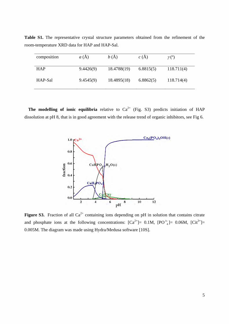
Table S1. The representative crystal structure parameters obtained from the refinement of the
room-temperature XRD data for HAP and HAP-Sal.
composition a (Å) b (Å) c (Å) (º)
HAP 9.4426(9) 18.4788(19) 6.8815(5) 118.711(4)
HAP-Sal 9.4545(9) 18.4895(18) 6.8862(5) 118.714(4)
The modelling of ionic equilibria relative to Ca2+ (Fig. S3) predicts initiation of HAP
dissolution at pH 8, that is in good agreement with the release trend of organic inhibitors, see Fig 6.
Figure S3. Fraction of all Ca2+ containing ions depending on pH in solution that contains citrate
and phosphate ions at the following concentrations: [Ca2+]= 0.1M, [PO 34 ]= 0.06M, [Cit3+]=
0.005M. The diagram was made using Hydra/Medusa software [10S].
6
References:
1S. Houwena J. A.M.; Cresseya G.; Cresseyb B. A.; Valsami-Jonesa E. J. Cryst. Growth. 2003,
249, 572-583.
2S. Mitsionis A. I.; Vaimakis T. C.; Trapalis C. C. J. Ceram Inter. 2010, 36, 623-634.
3S. Elliott J.C. Structure and Chemistry of the Apatites and Other Calcium Orthophosphates,
Elsevier: London, 1994; Vol 18, p. 111-116.
4S. Rodriguez-Carvajal J. Phys. B: Condensed Matter 1993, 192, 55-69.
5S. Ikoma T.; Yamazaki A.; Nakamura S.; Akao M. J. Solid State Chem. 1999, 144, 272-276.
6S. Suetsugu Y.; Tanaka J. J. Mater. Sci.: Materials in Medicine 2002, 13, 767-772.
7S. Pritzkow W.; Rentsch H. Crystal Research and Tech. 1985, 20, 957-960.
8S. Wilson R.M.; Elliot J.C.; Dowker S.E.P. J. Solid State Chem. 2003, 174, 132-140.
9S. Elliott J. C.; Mackie P.E.; Young R.A. Science 1973, 180, 1055-1057.
10S. Puigdomenech, I. Program MEDUSA (Make equilibrium diagrams using sophisticated
algorithms) 1999 Royal Institute of Technology, Stockholm