Embed Size (px)
Citation preview

JST: Smart Systems and Devices
Volume 31, Issue 1, May 2021, 100-107
100
Hydrostatic Pressure Distribution of Oil Lubrication Film for Internal
Gear Motors and Pumps: Solution of Resistance Network
Pham Trong Hoa University of Communications and Transport, Hanoi, Vietnam
*Email: [email protected], [email protected]
Abstract
Oil thin film lubrication is very popular and important in the field of fluid power and tribology science. It is widely used in all kinds of rotating machines. Its role is to separate the relative rotating surfaces to reduce friction, absorb vibration, protect surfaces, and produce load-carrying against an external load. The capacity of the oil lubrication film plays an important role in dynamic behavior, the life-cycle performance of the rotating machinery as well as the systems. During operation, if the oil film is damaged, it will cause the relative rotating surfaces to fail much sooner before the damage of components of the machine. This paper introduces the resistance network model to calculate the hydrostatic pressure distribution of the oil lubrication film. The effect of geometry and working parameters on the pressure distribution is then analyzed. Among these parameters, the calculation results point out that the radial and axial clearance, as well as the eccentricity of the ring gear, have a significant effect on the hydrostatic pressure distribution. The pressure profile is also simulated by using the CFD software in order to compare and validate the accuracy of the calculation results. With the solution of resistance network model, it is easy and quick to calculate the hydrostatic pressure distribution comparing to CFD. It saves time for designers at the early design stage.
Keywords: Internal gear pump, hydrostatic lubrication, oil lubrication film, resistance network model.
1. Introduction*
Hydrodynamic and hydrostatic lubrication regimes are very common in the field of rotating machines. For hydrodynamic lubrication regimes, the capacity of the oil lubrication film is produced by the relative speed of the rotor compared to its housing. Therefore, this lubrication regime is suitable in case of high rotating speed. Whilst, for hydrostatic lubrication regime, it is a type of lubrication which uses the high external pressure oil to feed into the gap between the relative rotating surfaces of the machine. The pressure of the oil lubrication produces the capacity for the oil film to against with the external load. Hydrostatic lubrication is suitable for heavy external load and slow rotation of the shaft. Lots of research so far [1-5] have been studied the effect of hydrostatic pressure distribution on the stiffness and damper of the oil film.
Internal gear motor and pump is one of the most common types of motor and pump in the field of hydraulic power application due to its simplicity, easy assembly, and economy. Unlikely to other rotating machines, for internal gear motor and pump, the oil lubrication mostly operates in a hybrid lubrication mode. In this case, the oil film contains simultaneously two components at the same time, i.e., hydrostatic and hydrodynamic. In order to obtain the
ISSN: 2734-9373 https://doi.org/10.51316/jst.150.ssad.2021.31.1.13 Received: 19 July 2020; accepted: 04 February 2021
pressure distribution of the oil in the thin film thickness, CFD now is a popular method used by lots of researchers [6-8]. CFD software brings lots of advantages for simulation such as the accuracy. However, it also contains some disadvantages such as it takes much simulation time. Moreover, we need to create specific CAD data for different simulation models. This means that if we want to change just only one geometric parameter, we need to build a new CAD model for CFD simulation. It takes much time in case of various changes of geometric parameters. Opitz in [9] used the hydraulic resistance model to calculate the hydrostatic pressure for journal bearing.
In this paper, the resistance network model for the calculation of the pressure distribution of the oil lubrication film between the ring gear and its housing is introduced. The CFD simulation is then also performed to compare with the RNM calculation. The results point out that the shape, values, and trends of the pressure distribution for both cases are almost identical. Base on the comparison results as well as due to lots of advantages of the RNM, it can be concluded that the RNM is easy and quick to obtain the hydrostatic pressure distribution in case of the internal gear motor and pump.
2. Geometry of Internal Gear Motor and Pump
The working oil is supplied directly into the small gap between the outer ring gear and the inner housing. It will generate the oil film thickness from high pressure chamber. The cross section of the

JST: Smart Systems and Devices
Volume 31, Issue 1, May 2021, 100-107
101
internal gear motor and pump is described in Fig.1. The oil pressure in the high pressure chamber produces the radial force acting on the ring gear. The value of the applied force is dependent on the values of oil pressure as well as the area of the chamber. This means that for specific IGMaP, the applied force acting on ring gear changes accordingly to the change of the oil pressure. In the studies [10-11], Pham pointed out that during operating the ring gear center is eccentrical with the housing center owning to the radial force. The value of eccentricity is dependent on the values of the applied force.
Nominal radial clearance is the distance in radial direction between the outer ring gear to inner housing surface when the ring gear and housing are centered. The nominal radial clearance is presented in Fig.2. Nominal axial clearance is the distance between the ring gear side to the housing side in case of the ring
gear and housing is centered in an axial direction. The nominal axial clearance is described in Fig.3.
The development of the oil film pressure distribution is dependent on the oil film thickness. Meanwhile, the oil film thickness is different over the circumferential direction. Based on the geometric configuration of the ring gear and housing as presented in Fig.4, the oil film thickness is as a function of the eccentricity can be formed as follows:
( , ) (1 cos )eh cθ θ= + (1)
where: 𝜀𝜀 is the eccentricity ratio; i.e., the ratio of eccentricity to radial clearance (e/c); 𝜃𝜃 is the angle from the centre line (ZZo) to the specific point (H) along with the circumferential direction; c is the radial clearance; i.e., the difference between the radius of the housing (Rh) and the ring gear (Rg).
Fig. 1. The section of internal gear motor and pump
Fig. 2. Radial clearance
Fig. 3. Axial clearance
Fig. 4. Geometry of the ring gear

JST: Smart Systems and Devices
Volume 31, Issue 1, May 2021, 100-107
102
3. Resistor Network Model Formation
Definition of hydraulic resistance: The hydraulic resistance is defined in the same way as the electric one [9]. Corresponding to Ohm’s law
VoltageResistanceCurrent
=
which can be written as,
PRQ
= (2)
The capillary in the supply line may be considered as constant flow resistance. The fluid resistance will appear when the lubrication oil flows in the film thickness. This resistance depends upon the value of the film thickness. Based on the electrical diagram, it allows us to apply the formulas and symbols for the calculation of flow (Q) and pressure (P).
The resistance of a capillary restrictor
4
128 cc
c
lRdµ
π= (3)
For a channel of circular cross-section (total length L and radius R):
4
8cs
LRRµπ
= (4)
Resistance of the axial direction can be calculated as the resistance of a rectangular cross-section
3
12
1 0.63r
lRhw
µ=
∆ − ∆
(5)
Resistance of a thin film thickness is a function of the oil film height (h):
3
1tR
h= (6)
Substitution of the oil film thickness into (1) yields:
( ) 31
1 costR
c ε θ= +
(7)
The resistance due to the changing of the oil film thickness is dependent on ring gear eccentricity ( ε ) and position in the circumferential direction ( θ).
In a network of channels, equivalent resistances can be computed (as in electrokinetics):
1. Two channels in series have an equivalent resistance: Rh=Rh1+Rh2,
2. Two channels in parallel have an equivalent resistance: 1/Rh=1/Rh1+1/Rh2.
These laws provide useful tools for the design of complex networks. Actually, Kirchhoff’s laws for electric circuits apply, being modified in:
1. The sum of low rates on a node of the circuit is zero
2. The sum of pressure differences on a loop is zero
Fig. 5. Risistance network model for calculation of static pressure for IGMaP
in which, Rrgl and Rrgr are flow resistance over the circumferential direction in left and right sides of ring gear, they are calculated by (3); Rfgl and Rfgr are flow resistance over the circumferential direction in left and right sides of fixed gear, they are calculated by (4); Ral and Rar are flow resistance over the radial direction in left and right sides of the ring gear, they are calculated by (5); Rofl and Rofr are flow resistance through the circumferential direction in left and right sides of oil film thickness, they are calculated by (7); Roi is the flow resistance at the pressure calculation position (pi). 4. Results and Discussion
The specifications of the IGMaP is described in Table 1.
Table 1. Specifications of the motor/pump
Parameter Symbol Values Unit Displacement V 63.5 cm³/rev Maximum pressure
p 25 MPa
Maximum speed
n 2000 rpm
Diameter of the ring gear
D 0.115 m
Length of the ring gear
L 0.034 m
Radial clearance
c 80.10-6 mµ
Axial clearance ∆ 30.10-6 mµ Working oil (lubrication oil)
- HLP 46 -
Oil Viscosity µ 0.041 Pas Oil temperature T 40 °C
JST: Smart Systems and Devices
Volume 31, Issue 1, May 2021, 100-107
103
4.1. Effect of Working Pressure on the Hydrostatic Pressure Profile
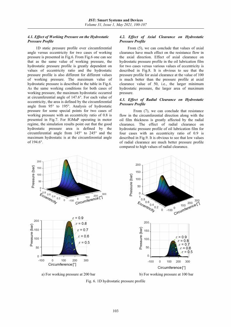
1D static pressure profile over circumferential angle versus eccentricity for two cases of working pressure is presented in Fig.6. From Fig.6 one can see that as the same value of working pressure, the hydrostatic pressure profile is greatly dependent on values of eccentricity ratio and the hydrostatic pressure profile is also different for different values of working pressure. The maximum value of hydrostatic pressure is described in the table in Fig.6. As the same working conditions for both cases of working pressure, the maximum hydrostatic occurred at circumferential angle of 147.6°. For each value of eccentricity, the area is defined by the circumferential angle from 95° to 195°. Analysis of hydrostatic pressure for some special points for two cases of working pressure with an eccentricity ratio of 0.8 is presented in Fig.7. For IGMaP operating in motor regime, the simulation results point out that the good hydrostatic pressure area is defined by the circumferential angle from 145° to 245° and the maximum hydrostatic is at the circumferential angle of 194.6°.
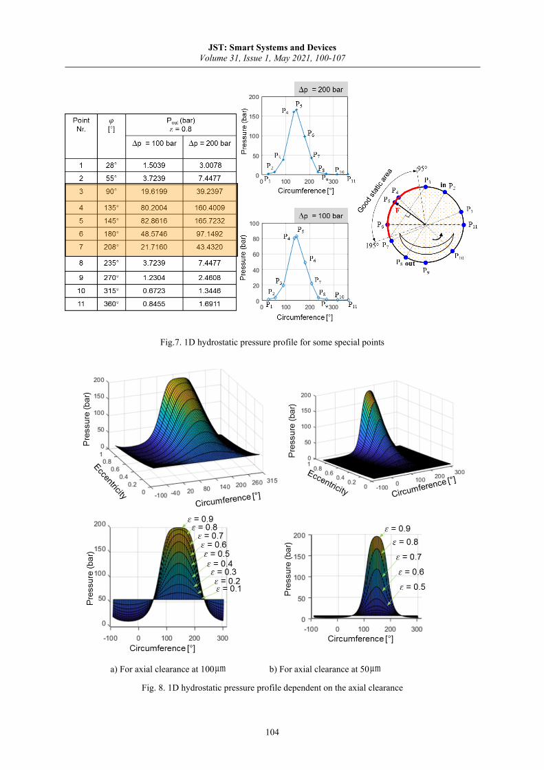
4.2. Effect of Axial Clearance on Hydrostatic Pressure Profile
From (5), we can conclude that values of axial clearance have much effect on the resistance flow in the axial direction. Effect of axial clearance on hydrostatic pressure profile in the oil lubrication film for two cases versus various values of eccentricity is described in Fig.8. It is obvious to see that the pressure profile for axial clearance at the value of 100 is much better than the pressure profile at axial clearance value of 50, i.e., the larger minimum hydrostatic pressure, the larger area of maximum pressure.
4.3. Effect of Radial Clearance on Hydrostatic Pressure Profile
From (7), we can conclude that resistance flow in the circumferential direction along with the oil film thickness is greatly affected by the radial clearance. The effect of radial clearance on hydrostatic pressure profile of oil lubrication film for four cases with an eccentricity ratio of 0.9 is described in Fig.9. It is obvious to see that low values of radial clearance are much better pressure profile compared to high values of radial clearance.
a) For working pressure at 200 bar b) For working pressure at 100 bar
Fig. 6. 1D hydrostatic pressure profile
JST: Smart Systems and Devices
Volume 31, Issue 1, May 2021, 100-107
104
Fig.7. 1D hydrostatic pressure profile for some special points
a) For axial clearance at 100 mµ b) For axial clearance at 50 mµ
Fig. 8. 1D hydrostatic pressure profile dependent on the axial clearance

JST: Smart Systems and Devices
Volume 31, Issue 1, May 2021, 100-107
105
a) For radial clearance at 150 mµ
b) For radial clearance at 100 mµ
c) For radial clearance at 75 mµ
d) For radial clearance at 50 mµ
Fig. 9. 1D hydrostatic pressure profile dependent on radial clearance
a) RNM calculation results and comparison b) CFD simulation result
Fig. 10. 1D hydrostatic pressure distribution for working pressure at 200 bar

JST: Smart Systems and Devices
Volume 31, Issue 1, May 2021, 100-107
106
4.4 Hydrostatic Pressure Profile Comparison between the RNM and CFD Results
Resistance network model is coded in Matlab Software R2018a and then integrated into a calculation tool in house. According to Pham [10, 11], due to similarities between the ring gear/housing and journal/bearing it allows us to apply the mobility method to calculate the eccentricity of ring gear. Mobility method is also integrated into this calculation tool. CFD simulation is performed with the help of Ansys Fluent. Input parameters for simulation and calculation are presented in Table 2.
Hydrostatic pressure profile of the oil film lubrication for CFD simulation result and comparison with the RNM result are presented in Fig.10.
Table 2. Geometric and working parameters
Parameters Symbol Values Unit Working pressure p 250 bar
Working oil temperature T 40 °C
Eccentricity ratio 0.798 -
Radial clearance c 60.10-6 m
Axial clearance 50.10-6 m
It is obviously to see that the pressure profile for RNM is almostl the same as the pressure profile procedured by CFD simulation results. The maximum pressure and the tendatation of pressure distribution agree very well. The position of maximum hydrostatic pressure is at angle of 194.45°. The minimum pressure according to RNM results is slightly smaller than the CFD simulation results. However, for CFD simulations, it takes 2 hours and 17 minutes to finish simulattion. Meanswhile for RNM it does not take the time, about 0.05 second. This is the great difference.
5. Conclusions
Based on the calculation and simulation results presented in this study, some conclusions can be drawn as follows:
• By the use of the Resistance Network Model, the 1D pressure profile for IGMaP can be easily and quickly calculated with sufficient results compared to CFD simulation.
• The good static pressure area of oil lubrication film is in a range from 95° to 195° operating as pump regime and angle from 145° to 245° for motor regime.
• Values of maximum static pressure of oil film is dependent on the eccentricity of ring gear.
• For large value of axial clearance is better for hydrostatic pressure profile whilst for small value of radial clearance is better for static pressure.
• Resistance network model combining with the finite difference method can be used to calculate the hybrid pressure profile of oil film for IGMaP.
Acknowledgements
This research is funded by Vietnam National Foundation for Science and Technology Development (NAFOSTED) under grant number 107.03-2019.17.
References [1]. J. Li, Y. Chen, Y. C. Yu, Z. X. Tian, and Y. Huang,
The Numerical Analysis of the Velocity and Pressure Distribution of the Oil Film in Heavy Hydrostatic Thrust Bearing, Appl. Mech. Mater., vol. 541–542, pp. 658–662, 2014. https://doi.org/10.4028/www.scientific.net/AMM.541-542.658
[2]. T. Shoyama and K. Fujimoto, Analytical Prediction of Dynamic Properties of O-Ring with Hydrostatic Pressure Distribution, J. Appl. Mech., vol. 85, no. 12, p. 121001, 2018. https://doi.org/10.1115/1.4041162
[3]. A. Walicka and E. Walicki, Pressure distribution in a curvilinear hydrostatic bearing lubricated by a micropolar fluid in the presence of a cross magnetic field, Lubr. Sci., vol. 17, no. 1, pp. 45–52, 2004. https://doi.org/10.1002/ls.3010170104
[4]. M. V. Makarov, Effect of the hydrostatic pressure on the vertical distribution of Laminaria saccharina (L.) lamouroux in the Barents Sea, Oceanology, vol. 51, no. 3, pp. 457–464, 2011. https://doi.org/10.1134/S0001437011030155
[5]. H. Aboshighiba, A. Bouzidane, M. Thomas, F. Ghezali, A. Nemchi, and A. Abed, Pressure distribution in orifice-compensated turbulent hydrostatic bearing with fluid inertia effects using numerical simulations via Navier-Stokes, Tribol. - Mater. Surfaces Interfaces, vol. 11, no. 1, pp. 19–29, 2017. https://doi.org/10.1080/17515831.2017.1288396
[6]. Vijay, K.D., Satish, C., and Pandey, K. N., Effect of the groove dimensions and orientation on the static and dynamic performance of non-recessed hybrid journal bearing, Proceedings of the Twenty-Third International Conference on Systems Engineering, Switzerland 2015, pp. 555-560, https://doi.org/10.1007/978-3-319-08422-0_7
[7]. Vijay, K.D., Satish, C., Pandey, K.N., Analysis of Hybrid (Hydrodynamic/ Hydrostatic) Journal
ε
∆

JST: Smart Systems and Devices
Volume 31, Issue 1, May 2021, 100-107
107
Bearing, Advanced Materials Research, Vol. 650, pp. 385-390, Jan. 2013, https://doi.org/10.4028/www.scientific.net/AMR.650.385
[8]. Xiu, S.C., Xiu, P.B., and Gao, S.Q., Simulation of Temperature Field of Oil Film in Super-high Speed Hybrid Journal Bearing Based on FLUENT, Advanced Materials Research, Vols. 69-70 (2009) pp 296-300. https://doi.org/10.4028/www.scientific.net/AMR.69-70.296
[9]. B. H. Opitz, Pressure pad bearings, pp. 100–115, 1967. https://doi.org/10.1243/PIME_CONF_1967_182_011_02
[10]. Trong Hoa Pham, Hybrid method to analysis the dynamic behavior of the ring gear for the internal gear motors and pumps, Journal of Mechanical Science and Technology, Vol. 33, No. 2, pp. 602-612, 2019. https://doi.org/10.1007/s12206-019-0114-7
[11]. Pham, T.H., Müller, L., Weber, J., Dynamically loaded the ring gear in the internal gear motor/pump: Mobility of solution, Journal of Mechanical Science and Technology, Vol. 32, No. 7, pp. 3023–3035, 2018. https://doi.org/10.1007/s12206-018-0605-y


![Film forming behavior in thin film lubrication at high speeds · film [19, 20]. The asymmetric film thickness distribution induced by the centrifugal effects must be considered for](https://img.dokumen.tips/doc/110x75/5f75c63abc89e3120e1737fe/film-forming-behavior-in-thin-film-lubrication-at-high-speeds-film-19-20-the.jpg)