Embed Size (px)
Citation preview
HYDROGRAPHIC SURVEY OF LAKE HUDSON
Final Report
October 23, 2008
Prepared by: Oklahoma Water Resources Board
2
TABLE OF CONTENTS TABLE OF CONTENTS.................................................................................................... 2 TABLE OF FIGURES ........................................................................................................ 3 TABLE OF TABLES.......................................................................................................... 3 INTRODUCTION .............................................................................................................. 4 LAKE BACKGROUND..................................................................................................... 4
History......................................................................................................................... 4 Lake Information......................................................................................................... 4
HYDROGRAPHIC SURVEYING PROCEDURES.......................................................... 6 Pre-survey Planning .................................................................................................... 6
Boundary File.......................................................................................................... 6 Set-up ...................................................................................................................... 6
Field Survey ................................................................................................................ 6 Method .................................................................................................................... 6 Technology.............................................................................................................. 6 Survey ..................................................................................................................... 7 Quality Control/Quality Assurance......................................................................... 7
Data Processing......................................................................................................... 10 GIS Application ........................................................................................................ 10
RESULTS ......................................................................................................................... 11 SUMMARY ...................................................................................................................... 11 REFERENCES.................................................................................................................. 12 APPENDIX A: Sound Velocity Profile ........................................................................... 13 APPENDIX B: Area-Capacity Data ................................................................................ 20 APPENDIX C: Lake Hudson Bathymetric Maps ............................................................ 26

3
TABLE OF FIGURES Figure 1: Location map for Lake Hudson. .................................................................................. 5 Figure 2: Histogram of relative depth distribution at cross check lines - in standard deviation. 9 Figure A. 1: Sound Velocity Profiles for November 6, 7, 8, and 13, 2006.............................. 16 Figure A. 2: Sound Velocity Profiles for November 14, 27, 28, and 29, 2006........................ 17 Figure A. 3: Sound Velocity Profiles for December 5, 6, 12, and 13, 2006. ........................... 18 Figure A. 4: Sound Velocity Profiles for December 14, 2006 and March 28 and 29, 2007.... 19 Figure B. 1. Capacity-Area Curve ............................................................................................ 25 Figure C. 1: Lake Hudson Bathymetric Map with 5-foot Contour Intervals. ........................... 27 Figure C. 2: Lake Hudson Shaded Relief Bathymetric Map. ................................................... 28 Figure C. 3: Lake Hudson Collected Data Points. .................................................................... 29 TABLE OF TABLES Table 1: Area and Volume Comparisons of Lake Hudson at Conservation Pool Elevation
(619.0 ft). ........................................................................................................................... 11 Table A. 1: Sound Velocity Profile Data (ft/sec) for November 6 – 29, 2006. ........................ 14 Table A. 2: Sound Velocity Profile Data (ft/sec) for December 5, 2006 - March 29, 2007. .... 15 Table B. 1: Lake Hudson Capacity/Area by 0.1-ft Increments................................................. 21 Table B. 2: Lake Hudson Capacity/Area by 0.1-ft Increments (cont). ..................................... 21 Table B. 3: Lake Hudson Capacity/Area by 0.1-ft Increments (cont). ..................................... 22 Table B. 4: Lake Hudson Capacity/Area by 0.1-ft Increments (cont). ..................................... 23

4
LAKE HUDSON (MARKHAM FERRY RESERVOIR) HYDROGRAPHIC SURVEY REPORT
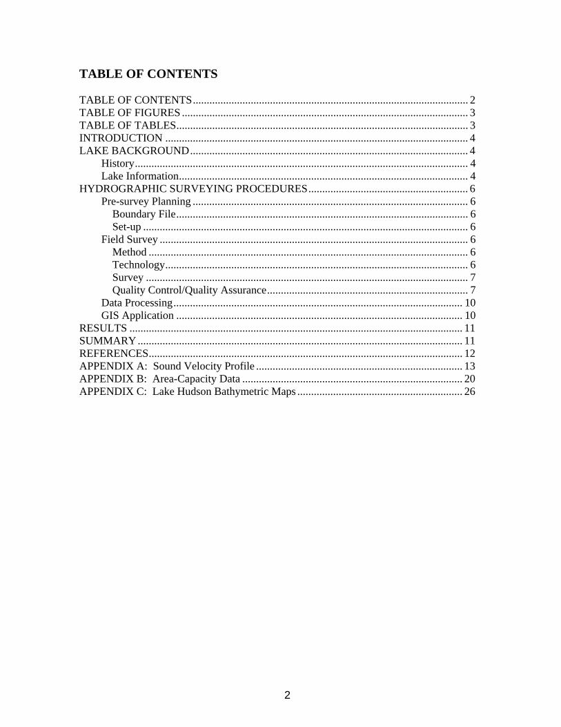
INTRODUCTION The Oklahoma Water Resources Board (OWRB) conducted a hydrographic survey of Lake Hudson (Markham Ferry Reservoir) from November to December of 2006 and March of 2007. The purpose of the study was to collect hydrographic data of Lake Hudson and convert this information into an area-elevation-volume table up to the conservation pool elevation. The information produced will serve as a base to establish the location and rate of sedimentation in the conservation pool for future surveys. LAKE BACKGROUND History On August 18, 1941, the Flood Control Act authorized the construction of what was initially called the Markham Ferry Reservoir. In July of 1946, it was incorporated into the Arkansas River multi-purpose plan by the River and Harbor Act. The Lake’s authorization was further modified in July 1954 by Public Law 476. This authorized the Grand River Dam Authority (GRDA) to construct Lake Hudson. Construction of Lake Hudson began in January of 1962 and was completed in 1964 (USACE, 1992). The lake is used for flood control and hydroelectric power and was authorized by the Flood Control Act approved August 18, 1941. The lake is a multi-purpose project for flood control, hydropower, and navigation. Lake Information Lake Hudson is located in Mayes County in the Arkansas River Basin on Grand (Neosho) River. The Robert S. Kerr Dam located on Lake Hudson is approximately 2 miles northwest of Locust Grove and 8 miles southeast of Pryor. A general location map of Lake Hudson is shown on the following page as Figure 1. Based on the original sediment surveys, Lake Hudson covers an area of 10,900 acres and has a capacity of 200,400 acre-feet at the top of the conservation pool elevation of 619 ft NGVD. The reservoir has a length of 29.6 miles and an estimated total of 200 miles of shoreline at the top of the conservation pool (USACE, 1992). GRDA owns and is the regulating agency of Lake Hudson. The Tulsa District of the US Army Corps of Engineers (USACE), by authority of the Flood Control Act of 1944 (Public Law 78-534, 58 Stat. 890, 33 U.S.C. 709), is responsible for prescribing regulation for the use of the flood control storage in the lake between elevations 619 and 636 ft NGVD (USACE, 1992).
5
Figure 1: Location map for Lake Hudson.
Lake HudsonLocation Map
~
J..j}'
Jl
/-o 1Miles
jL" k_'.,h,"' ("~'0
'. .~
""'-~"""
te 1
~ I T
rr r t1 ~
f J 1Hl L

6
HYDROGRAPHIC SURVEYING PROCEDURES The process of surveying a reservoir uses a combination of Geographic Positioning System (GPS) and acoustic depth sounding technologies that are incorporated into a hydrographic survey vessel. As the survey vessel travels across the lake’s surface, the echosounder gathers multiple depth readings every second. The depth readings are stored on the survey vessel’s on-board computer along with the positional data generated from the vessel’s GPS receiver. The collected data files are downloaded daily from the computer and brought to the office for editing after the survey is completed. During editing, data “noise” is removed or corrected, and average depths are converted to elevation readings based on the daily-recorded lake level elevation on the day the survey was performed. Accurate estimates of area-capacity can then be determined for the lake by building a 3-D model of the reservoir from the corrected data. The process of completing a hydrographic survey includes four steps: pre-survey planning, field survey, data processing, and GIS application. Pre-survey Planning Boundary File The digitized boundary of Lake Hudson was produced from the 1995 black and white US Geological Survey (USGS) digital ortho quarter quads (DOQQs) of Mayes County, Oklahoma at a scale of 1:1,500. The lake elevation at the time of the 1995 DOQQ was 619.17 ft NGVD. The reservoir boundary was digitized in NAD 1983 State Plane Coordinates (Oklahoma North-3501). The 2003 United States Department of Agriculture-Farm Service Agency-Aerial Photography Field Office (USDA-FSA-APFO) color DOQQ of Mayes County was also used for reference. The lake elevation at the time the 2003 DOQQ was taken was 619.9 ft NGVD. Set-up HYPACK software from Hypack, Inc. was used to assign geodetic parameters, import background files, and create virtual track lines (transects). The geodetic parameters assigned were State Plane NAD 83 Zone OK-3501 Oklahoma North with distance units and depth as US Survey Feet. The survey transects were spaced according to the accuracy required for the project. The survey transects within the digitized reservoir boundary were at 500 ft increments and ran perpendicular to the original stream channels and tributaries. Approximately 285 virtual transects were created for the Lake Hudson project not including channel track lines, which were created after the initial surveying of the lake transects. Field Survey Method The procedures followed by the OWRB during the hydrographic survey adhere to U.S. Army Corps of Engineers (USACE) standards (USACE, 2002). The quality control and quality assurance procedures for equipment calibration and operation, field survey, data processing, and accuracy standards are presented in the following sections. Technology The Hydro-survey vessel was an 18-ft aluminum Silverstreak hull with cabin, powered by a single 115-Horsepower Mercury outboard motor. Equipment used to conduct the survey included: a ruggedized notebook computer; Syqwest Bathy 1500 Echo Sounder, with a depth resolution of 0.1 ft; Trimble Navigation, Inc. Pro XR GPS receiver with differential global

7
positioning system (DGPS) correction; and an Odom Hydrographics, Inc, DIGIBAR-Pro Profiling Sound Velocimeter. A 12V battery and inverter provided the power supply to the equipment. The software used was HYPACK. Survey A two-man survey crew was used during the project. Data collection for Lake Hudson occurred on 11/06-08/2006, 11/13-14/2006, 11/27-29/2006, 12/05-06/2006, 12/13-14/2006, and 2/28-29/2007. The average water level elevation in November and December 2006 was approximately 618.4 ft NGVD. The average elevation in March 2007 was approximately 619 ft NGVD. Data collection began at the dam and moved north up the reservoir. The survey crew followed the parallel transects created during the pre-survey planning while collecting depth soundings and positional data. Data was also collected along a path parallel to the shoreline at a distance that was determined by the depth of the water and the draft of the boat. This was usually in a water depth of two to three feet. Areas with depths less than what could accommodate the boat were avoided. Quality Control/Quality Assurance While on board the Hydro-survey vessel, the Syqwest Bathy 1500 Echo Sounder was calibrated using A DIGIBAR-Pro Profiling Sound Velocimeter, by Odom Hydrographics. The sound velocimeter measures the speed of sound at incremental depths throughout the water column. The factors that influence the speed of sound—depth, temperature, and salinity—are all taken into account. Deploying the unit involved lowering the probe, which measures the speed of sound, into the water to the calibration depth mark to allow for acclimation and calibration of the depth sensor. The unit was then gradually lowered at a controlled speed to a depth just above the lake bottom, and then was raised to the surface. The unit collected sound velocity measurements in feet/seconds (ft/sec) at 1 ft increments on both the deployment and retrieval phases. The data was then reviewed for any erroneous readings, which were then edited out of the sample. The sound velocity corrections were then applied to the to the raw depth readings. The average speed of sound in the water column ranged from 4,711.7 ft/sec to 4,808.5 ft/sec during the Lake Hudson survey. The sound velocity profiles for each date of surveying are shown in APPENDIX A: Sound Velocity Profile. A quality assurance cross-line check was undertaken on intersecting transect lines and channel track lines to assess the estimated accuracy of the survey measurements. The overall accuracy of an observed bottom elevation or depth reading is dependent on many random and systematic errors that are present in the measurement processes used to determine that depth readings. Depth measurements contain both random errors and systematic bias. Biases are often referred to as systematic errors and are often due to observational errors. Examples of bias include a bar check calibration error, tidal errors, or incorrect squat corrections. Bias, however, does not affect the repeatability, or precision, of results. The precision of depth readings is affected by random errors. These are errors present in the measurement system that cannot be easily reduced by further calibration. Examples of random error include uneven bottom topography, bottom vegetation, positioning error, extreme listing of survey vessel, and speed of sound variation in the water column. An assessment of the accuracy of an individual depth or bottom elevation must fully consider all the error components contained in the observations that were used to determine that measurement. Therefore, the ultimate accuracy must be estimated (thus the use of the term “estimated accuracy”) using statistical estimating measures (USACE, 2002).

8
The depth accuracy estimate is determined from comparing depth readings between readings taken at an intersection of two lines and computing the difference. The mean difference of all intersection points used to calculate the mean difference (MD). The mean difference represents the bias present in the survey. The standard deviation (SD), representing the random error in the survey, is also calculated. The mean difference and the standard deviation are then used to calculate the Root Mean Square (RMS) error. The RMS error estimate is used to compare relative accuracies of estimates that differ substantially in bias and precision (USACE, 2002). According the USACE standards, the RMS should not exceed a tolerance of ± 2.0 ft for this type of survey. This is done to verify compliance with the resultant depth accuracy of ± 2.0 ft at the 95% confidence level. This simply means that on average, 19 of every 20 observed depths will fall within the specified accuracy tolerance. HYPACK Cross Statistics program was used to assess vertical accuracy and confidence measures of acoustically recorded depths. The program computes the sounding difference between intersecting lines of single beam data. The program provides a report that shows the standard deviation and mean difference. A total of 114 cross-sections points were used to compute error estimates. A mean difference of 0.0 ft and a standard deviation of 1.09 ft were computed from a number of 114 data points. Using the following formulas, a 95% depth accuracy of ± 2.1 ft was calculated. 22 MDSDRMS += RMSaccuracydepthRMS ×= 96.1%)95( where: MD = mean difference SD = standard deviation RMS = root mean square error An RMS of ± 2.1 ft with a 95% level is slightly higher than the USACE’s minimum performance standard of ± 2.0 ft for this type of survey. A mean difference, or bias, of 0.0 ft is well below the USACE’s standard maximum allowable bias of ± 0.5 ft for this type of survey. It must be remembered that minimizing constant bias errors is far more important than reducing deviations (USACE, 2002). The data plotted in Figure 2 illustrates that the measurements have somewhat low precision but high accuracy (USACE, 2002).

9
Quality Assurance Cross-line Check
0
5
10
15
20
25
30
35
40
45
50
-5s -4s -3s -2s -1s +1s +2s +3s +4s +5s
Data Distribution
Num
ber o
f Obs
erva
tions
Figure 2: Histogram of relative depth distribution at cross check lines - in standard deviation.
The GPS system is an advanced high performance geographic data-acquisition tool that uses DGPS to provide sub-meter positional accuracy on a second-by-second basis. Potential errors are reduced with differential GPS because additional data from a reference GPS receiver at a known position are used to correct positions obtained during the survey. Before the survey, Trimble’s Pathfinder Controller software was used to configure the GPS receiver. To maximize the accuracy of the horizontal positioning, the horizontal mask setting was set to 15 degrees and the Position Dilution of Precision (PDOP) limit was set to 6. The position interval was set to 1 second and the Signal to Noise Ratio (SNR) mask was set to 4. The United States Coast Guard reference station used in the Lake Hudson survey is located near Sallisaw, Oklahoma. The reference beacon system transmitted corrected signals in real time, so no post-processing corrections of position data were needed. The collected DGPS positions were converted to state-plane coordinate system using the HYPACK program. A latency test was performed to determine the fixed delay time between the GPS and single beam echo sounder. The timing delay was determined by running reciprocal survey lines over a channel bank. The raw data files were downloaded into HYPACK, LATENCY TEST program. The program varies the time delay to determine the “best fit” setting. A position latency of 0.1 seconds was produced and adjustments were applied to the raw data in the EDIT program.

10
Data Processing The collected data was downloaded from the field computer onto the OWRB computer network and data burned to a CD as a permanent record. After downloading the data, each raw data file was reviewed for accuracy and completeness using the EDIT program within HYPACK. The EDIT program allowed the user to assign transducer offsets, latency corrections, tide corrections, display the raw data profile, and review/edit all raw X, Y, and Z information. Collected data points that have inaccurate or absent depth or positional information were interpolated to be congruent with adjacent accurate points or deleted completely. Offset correction values of 3.2 ft. starboard, 6.6 ft. forward, and -1.1 ft. vertical were applied to all raw data along with a latency correction factor of 0.1 seconds. The speed of sound readings from the sound profiling velocimeter are documented in APPENDIX A: Sound Velocity Profile. Using HYPACK, TIDES program, a tide correction file was produced to account for the variance in lake elevation at the time in which data was collected. Within the EDIT program, the corrected depths were subtracted from the elevation reading to convert the depth in feet to an elevation. After editing the data for errors and correcting the spatial attributes (offsets and tide corrections), a data reduction scheme was needed. To accomplish this the data was resampled spatially at a 10 ft interval using the Sounding Selection program in HYPACK. The resultant data was saved and exported out as a xyz.txt file. The HYPACK data file for Lake Hudson is located at the end of the document on the CD entitled Hudson HYPACK/GIS Metadata. GIS Application Geographic Information System (GIS) software was used to process the edited XYZ data collected from the survey. The GIS software used was ArcGIS Desktop and ArcMap, version 9.1, from Environmental System Research Institute (ESRI). All of the GIS datasets created are in Oklahoma State Plane North Coordinate System referenced to the North American Datum 1983. Horizontal and vertical units are in feet. The edited data points in XYZ text file format were converted into ArcMap point coverage format. The point coverage contains the X and Y horizontal coordinates and the elevation and depth values associated with each collected point. Volumetric and area calculations were derived using a TIN surface model. The TIN model was created in ArcMap, using the collected survey data points and the lake boundary inputs. The TIN consists of connected data points that form a network of triangles representing the bottom surface of the lake. Approximately 131,373 data points were used to create the TIN model. The lake volume was calculated by slicing the TIN horizontally into planes 0.1 ft thick. The volume and area of each slice are shown in APPENDIX B: Area-Capacity Data. Contours, depth ranges, and the shaded relief map were derived from a digital elevation model grid. This grid was created using the ArcMap Topo to Raster Tool and had a spatial resolution of five feet. A low pass 3x3 filter was run to lightly smooth the grid to improve contour generation. The contours were created at a 5-ft interval using the ArcMap Contour Tool. The contour lines were edited to allow for polygon topology and to improve accuracy

11
and general smoothness of the lines. The contours were then converted to a polygon coverage and attributed to show 5-ft depth ranges across the lake. The bathymetric map of the lake is shown with 5-ft contour intervals in Appendix C. All geographic datasets derived from the survey contain Federal Geographic Data Committee (FGDC) compliant metadata documentation. The metadata describes the procedures and commands used to create the datasets. The GIS metadata file for Lake Hudson is located at the end of the document on the CD entitled Hudson HYPACK/GIS Metadata. RESULTS Results from the 2006-2007 OWRB survey indicate that Lake Hudson encompasses 11,029 acres and contains a cumulative capacity of 200,185 ac-ft at the conservation pool elevation (619 ft NGVD). The average depth for Lake Hudson was 18.2 ft with a maximum depth of 65 ft. SUMMARY Table 1 summarizes all surveys conducted of Lake Hudson at the conservation pool elevation. Based on the original sediment survey, Lake Hudson had an area of 10,900 acres and cumulative volume of 200,400 acre-feet of water at conservation pool elevation (USACE, 1992). The surface area of the lake has increased 1.5% or approximately 164 acres. Hudson Lake has had a less than a 0.1% decrease in capacity or a loss of approximately 178 acre-feet. However, caution should be used when directly comparing between the original survey and the 2006-2007 survey conducted by the OWRB. Different methods were used to collect the data and extrapolate capacity and area figures. It is the recommendation of the OWRB that another survey using the same method used in the 2006-2007 survey be conducted in 15 years.
Table 1: Area and Volume Comparisons of Lake Hudson at Conservation Pool Elevation (619.0 ft).
Survey Year Feature Original Survey 2006-2007
Area (acres) 10,865 11,029 Cumulative Volume (acre-feet) 200,363 200,185
Mean depth (ft) 18.44 18.15
12
REFERENCES U.S. Army Corps of Engineers (USACE). 1992. Water Control Manual – Markham Ferry Reservoir. U.S. Army Corps of Engineers (USACE). 2002. Engineering and Design - Hydrographic Surveying, Publication EM 1110-2-1003, 3rd version.

13
APPENDIX A: Sound Velocity Profile

14
Table A. 1: Sound Velocity Profile Data (ft/sec) for November 6 – 29, 2006. Depth 11/06/2006 11/07/2006 11/08/2006 11/13/2006 11/14/2006 11/27/2006 11/28/2006 11/29/2006
1 4802.8 4800.1 4795.5 4790.6 4784.1 4789.7 4794.72 4802.5 4802.7 4800.1 4795.5 4790.8 4784.0 4789.6 4794.73 4802.2 4801.6 4800.1 4795.5 4790.8 4783.7 4789.5 4794.74 4802.1 4801.4 4800.1 4795.5 4790.8 4783.3 4789.4 4794.65 4802.0 4801.1 4800.1 4795.1 4790.9 4783.0 4789.3 4794.66 4801.7 4801.0 4800.1 4794.8 4790.9 4782.5 4789.2 4794.67 4801.4 4800.9 4800.1 4794.8 4791.0 4782.1 4789.2 4794.68 4801.2 4800.8 4800.1 4794.8 4791.1 4782.0 4789.0 4794.69 4801.1 4800.8 4800.2 4794.5 4791.2 4782.0 4789.0 4794.6
10 4801.1 4800.7 4800.2 4794.5 4791.3 4781.8 4789.0 4794.611 4801.1 4800.7 4800.2 4794.5 4791.2 4781.7 4788.9 4794.612 4801.0 4800.7 4800.3 4794.5 4791.2 4781.7 4788.9 4794.613 4801.1 4800.7 4800.3 4794.5 4791.3 4781.7 4788.8 4794.514 4801.1 4800.7 4800.3 4794.5 4791.2 4781.6 4788.8 4794.415 4801.1 4800.7 4800.3 4794.5 4791.1 4781.5 4788.9 4794.316 4801.1 4800.7 4800.2 4794.5 4791.2 4781.5 4788.9 4794.317 4801.1 4800.7 4800.3 4794.5 4791.0 4781.6 4788.9 4794.318 4801.1 4800.7 4800.3 4794.5 4790.9 4781.6 4788.9 4794.219 4801.1 4800.7 4800.3 4794.5 4790.9 4781.6 4788.9 4794.120 4801.0 4800.6 4800.2 4794.8 4790.9 4781.6 4788.9 4794.021 4801.1 4800.7 4800.0 4794.8 4790.9 4781.6 4788.9 4793.922 4801.0 4800.6 4799.7 4794.8 4790.9 4781.6 4788.9 4793.823 4801.0 4800.5 4799.2 4794.8 4791.0 4781.6 4788.9 4793.824 4801.0 4800.3 4798.8 4794.8 4791.0 4781.6 4788.8 4793.725 4801.1 4800.1 4798.3 4794.8 4791.0 4781.6 4788.8 4793.726 4801.0 4799.9 4798.2 4794.8 4791.0 4781.6 4788.8 4793.827 4800.9 4799.6 4798.0 4794.8 4791.1 4781.6 4788.828 4800.8 4799.3 4797.7 4794.8 4791.1 4781.6 4788.729 4800.7 4799.0 4797.5 4794.8 4791.1 4781.6 4788.630 4800.5 4798.9 4797.4 4794.8 4791.1 4781.6 4788.531 4800.4 4798.8 4797.3 4794.8 4791.1 4781.6 4788.532 4800.2 4798.7 4797.0 4794.8 4791.0 4781.5 4788.433 4799.9 4798.6 4796.9 4794.8 4791.1 4781.5 4788.434 4799.9 4798.6 4796.6 4794.8 4791.1 4781.5 4788.335 4798.5 4796.1 4794.8 4791.1 4781.5 4788.236 4798.4 4795.7 4794.8 4791.1 4788.237 4798.4 4795.5 4794.8 4791.1 4788.338 4798.3 4795.4 4794.8 4791.2 4788.239 4798.3 4795.2 4794.8 4791.240 4798.2 4794.8 4794.8 4791.241 4798.1 4794.6 4794.8 4791.342 4798.0 4794.5 4794.8 4791.243 4798.0 4794.2 4794.844 4797.9 4794.1 4794.845 4797.7 4794.1 4794.846 4797.4 4794.0 4794.847 4797.1 4793.9 4794.548 4796.7 4793.8 4794.549 4796.3 4793.7 4794.550 4796.0 4793.7 4794.551 4795.9 4793.6 4794.552 4795.8 4793.6 4794.553 4795.7 4793.5
15
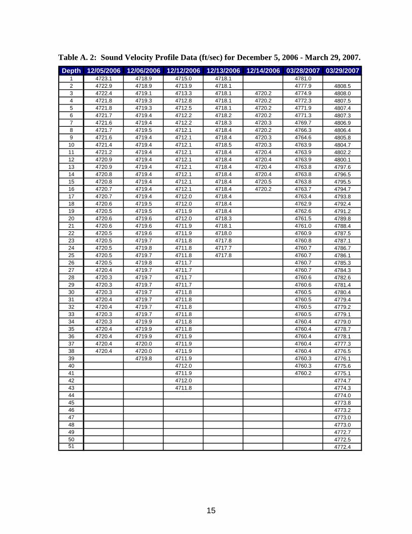
Table A. 2: Sound Velocity Profile Data (ft/sec) for December 5, 2006 - March 29, 2007. Depth 12/05/2006 12/06/2006 12/12/2006 12/13/2006 12/14/2006 03/28/2007 03/29/2007
1 4723.1 4718.9 4715.0 4718.1 4781.02 4722.9 4718.9 4713.9 4718.1 4777.9 4808.53 4722.4 4719.1 4713.3 4718.1 4720.2 4774.9 4808.04 4721.8 4719.3 4712.8 4718.1 4720.2 4772.3 4807.55 4721.8 4719.3 4712.5 4718.1 4720.2 4771.9 4807.46 4721.7 4719.4 4712.2 4718.2 4720.2 4771.3 4807.37 4721.6 4719.4 4712.2 4718.3 4720.3 4769.7 4806.98 4721.7 4719.5 4712.1 4718.4 4720.2 4766.3 4806.49 4721.6 4719.4 4712.1 4718.4 4720.3 4764.6 4805.8
10 4721.4 4719.4 4712.1 4718.5 4720.3 4763.9 4804.711 4721.2 4719.4 4712.1 4718.4 4720.4 4763.9 4802.212 4720.9 4719.4 4712.1 4718.4 4720.4 4763.9 4800.113 4720.9 4719.4 4712.1 4718.4 4720.4 4763.8 4797.614 4720.8 4719.4 4712.1 4718.4 4720.4 4763.8 4796.515 4720.8 4719.4 4712.1 4718.4 4720.5 4763.8 4795.516 4720.7 4719.4 4712.1 4718.4 4720.2 4763.7 4794.717 4720.7 4719.4 4712.0 4718.4 4763.4 4793.818 4720.6 4719.5 4712.0 4718.4 4762.9 4792.419 4720.5 4719.5 4711.9 4718.4 4762.6 4791.220 4720.6 4719.6 4712.0 4718.3 4761.5 4789.821 4720.6 4719.6 4711.9 4718.1 4761.0 4788.422 4720.5 4719.6 4711.9 4718.0 4760.9 4787.523 4720.5 4719.7 4711.8 4717.8 4760.8 4787.124 4720.5 4719.8 4711.8 4717.7 4760.7 4786.725 4720.5 4719.7 4711.8 4717.8 4760.7 4786.126 4720.5 4719.8 4711.7 4760.7 4785.327 4720.4 4719.7 4711.7 4760.7 4784.328 4720.3 4719.7 4711.7 4760.6 4782.629 4720.3 4719.7 4711.7 4760.6 4781.430 4720.3 4719.7 4711.8 4760.5 4780.431 4720.4 4719.7 4711.8 4760.5 4779.432 4720.4 4719.7 4711.8 4760.5 4779.233 4720.3 4719.7 4711.8 4760.5 4779.134 4720.3 4719.9 4711.8 4760.4 4779.035 4720.4 4719.9 4711.8 4760.4 4778.736 4720.4 4719.9 4711.9 4760.4 4778.137 4720.4 4720.0 4711.9 4760.4 4777.338 4720.4 4720.0 4711.9 4760.4 4776.539 4719.8 4711.9 4760.3 4776.140 4712.0 4760.3 4775.641 4711.9 4760.2 4775.142 4712.0 4774.743 4711.8 4774.344 4774.045 4773.846 4773.247 4773.048 4773.049 4772.750 4772.551 4772.4

16
4790 4792 4794 4796Speed of Sound (ft/s)
60
40
20
0
Dep
th (f
t)
Sound Velocity ProfileLake Hudson
11/13/2006
4792 4794 4796 4798 4800 4802Speed of Sound (ft/s)
60
40
20
0
Dep
th (f
t)
Sound Velocity ProfileLake Hudson
11/8/2006
4794 4796 4798 4800 4802 4804Speed of Sound (ft/s)
60
40
20
0
Dep
th (f
t)
Sound Velocity ProfileLake Hudson
11/7/2006
4799 4800 4801 4802 4803Speed of Sound (ft/s)
40
30
20
10
0
Dep
th (f
t)Sound Velocity Profile
Lake Hudson11/6/2006
Figure A. 1: Sound Velocity Profiles for November 6, 7, 8, and 13, 2006.

17
4792 4793 4794 4795Speed of Sound (ft/s)
30
25
20
15
10
5
0
Dep
th (f
t)
Sound Velocity ProfileLake Hudson
11/29/2006
4788 4789 4790 4791 4792Speed of Sound (ft/s)
40
30
20
10
0
Dep
th (f
t)
Sound Velocity ProfileLake Hudson
11/28/2006
4781 4782 4783 4784 4785Speed of Sound (ft/s)
40
30
20
10
0
Dep
th (f
t)
Sound Velocity ProfileLake Hudson
11/27/2006
4789 4790 4791 4792 4793Speed of Sound (ft/s)
50
40
30
20
10
0
Dep
th (f
t)Sound Velocity Profile
Lake Hudson11/14/2006
Figure A. 2: Sound Velocity Profiles for November 14, 27, 28, and 29, 2006.

18
4717 4717.5 4718 4718.5 4719 4719.5Speed of Sound (ft/s)
25
20
15
10
5
0
Dep
th (f
t)
Sound Velocity ProfileLake Hudson
12/13/2006
4711 4712 4713 4714 4715Speed of Sound (ft/s)
50
40
30
20
10
0
Dep
th (f
t)
Sound Velocity ProfileLake Hudson
12/12/2006
4718 4718.5 4719 4719.5 4720 4720.5Speed of Sound (ft/s)
40
30
20
10
0
Dep
th (f
t)
Sound Velocity ProfileLake Hudson
12/6/2006
4720 4721 4722 4723 4724Speed of Sound (ft/s)
40
30
20
10
0
Dep
th (f
t)Sound Velocity Profile
Lake Hudson12/5/2006
Figure A. 3: Sound Velocity Profiles for December 5, 6, 12, and 13, 2006.

19
4770 4780 4790 4800 4810Speed of Sound (ft/s)
60
50
40
30
20
10
0
Dpe
th (f
t)
Sound Velocity ProfileLake Hudson
03/29/2007
4760 4765 4770 4775 4780 4785Speed of Sound (ft/s)
50
40
30
20
10
0
Dpe
th (f
t)
Sound Velocity ProfileLake Hudson
03/28/2007
4719.5 4720 4720.5 4721 4721.5 4722Speed of Sound (ft/s)
16
12
8
4
0
Dpe
th (f
t)Sound Velocity Profile
Lake Hudson12/14/2006
Figure A. 4: Sound Velocity Profiles for December 14, 2006 and March 28 and 29, 2007.

20
APPENDIX B: Area-Capacity Data

21
Table B. 1: Lake Hudson Capacity/Area by 0.1-ft Increments.
.04 .14 .24 .34 .44 .54 .64 .74 .84 .94554 Area 0.000 0.000 0.000 0.001 0.001 0.002 0.003 0.004 0.006 0.008
Capacity 0.000 0.001 0.002 0.004 0.007 0.009 0.012 0.014 0.017 0.020555 Area 0.010 0.012 0.015 0.018 0.021 0.025 0.029 0.033 0.037 0.042
Capacity 0.023 0.026 0.029 0.032 0.035 0.038 0.041 0.044 0.048 0.052556 Area 0.048 0.054 0.060 0.067 0.074 0.082 0.090 0.099 0.108 0.119
Capacity 0.056 0.060 0.065 0.070 0.075 0.081 0.087 0.093 0.099 0.105557 Area 0.130 0.141 0.153 0.166 0.181 0.196 0.213 0.233 0.257 0.284
Capacity 0.112 0.119 0.127 0.135 0.146 0.163 0.186 0.216 0.253 0.291558 Area 0.32 0.35 0.39 0.43 0.48 0.53 0.59 0.65 0.71 0.78
Capacity 0.33 0.37 0.41 0.45 0.49 0.54 0.58 0.62 0.67 0.71559 Area 0.86 0.95 1.04 1.14 1.24 1.34 1.44 1.55 1.66 1.77
Capacity 0.88 0.91 0.94 0.97 1.00 1.03 1.05 1.08 1.12 1.15560 Area 1.89 2.01 2.13 2.26 2.39 2.52 2.66 2.80 2.96 3.13
Capacity 1.18 1.22 1.25 1.29 1.32 1.36 1.40 1.48 1.62 1.85561 Area 3.33 3.57 3.87 4.22 4.63 5.10 5.64 6.26 6.95 7.73
Capacity 2.20 2.66 3.21 3.79 4.42 5.08 5.79 6.53 7.32 8.15562 Area 8.6 9.5 10.6 11.7 13.0 14.4 15.9 17.6 19.4 21.5
Capacity 9.0 9.9 11.0 12.1 13.3 14.6 16.0 17.6 19.3 21.2563 Area 23.7 26.1 28.7 31.6 34.7 38.0 41.6 45.4 49.5 53.8
Capacity 23.2 25.3 27.4 29.7 32.0 34.4 36.9 39.5 42.3 45.4564 Area 59.3 66.1 73.0 80.0 87.0 94.1 101 108 116 123
Capacity 67.4 68.3 69.3 70.1 70.6 71.2 71.7 72.3 72.8 73.4565 Area 130 138 145 153 160 168 176 184 191 199
Capacity 73.9 74.5 75.1 75.6 76.2 76.8 77.3 78.0 78.7 79.6566 Area 207 215 224 232 240 249 258 267 276 285
Capacity 80.7 81.8 83.0 84.2 85.4 86.6 87.9 89.2 90.5 91.8567 Area 294 303 313 323 333 343 354 365 376 387
Capacity 93.4 95.2 97.1 99.3 102 104 107 110 114 117568 Area 399 412 424 437 451 465 479 494 509 525
Capacity 121 125 128 132 137 141 145 150 154 159569 Area 542 562 583 604 625 646 667 688 710 732
Capacity 201 204 206 208 210 212 214 216 218 219570 Area 754 776 799 821 844 867 890 914 937 961
Capacity 221 223 225 227 229 231 233 235 237 239571 Area 985 1009 1034 1058 1083 1108 1133 1159 1185 1211
Capacity 241 243 245 247 250 252 254 256 258 261572 Area 1237 1263 1290 1317 1344 1372 1399 1427 1456 1484
Capacity 263 265 268 270 273 276 278 281 284 287573 Area 1513 1542 1572 1601 1631 1662 1693 1724 1755 1787
Capacity 290 293 296 299 303 306 309 313 316 320574 Area 1820 1855 1890 1926 1961 1997 2033 2069 2105 2142
Capacity 348 350 352 354 356 358 360 362 364 366
Area in acres by tenth foot elevation incrementsElevation (ft NGVD)
LAKE HUDSON CAPACITY-AREA TABLEOKLAHOMA WATER RESOURCES BOARD
2006-2007 SurveyCapacity in acre-feet by tenth foot elevation increments
Table B. 2: Lake Hudson Capacity/Area by 0.1-ft Increments (cont).

22
.04 .14 .24 .34 .44 .54 .64 .74 .84 .94575 Area 2178 2215 2252 2290 2328 2365 2404 2442 2481 2519
Capacity 368 371 373 375 378 380 382 385 387 390576 Area 2558 2598 2637 2677 2718 2758 2799 2840 2881 2923
Capacity 392 395 397 400 403 406 409 412 416 419577 Area 2965 3007 3050 3093 3137 3181 3225 3270 3315 3360
Capacity 422 426 429 433 437 440 444 448 452 457578 Area 3406 3452 3499 3546 3594 3643 3692 3742 3792 3843
Capacity 461 466 471 476 482 488 494 501 508 516579 Area 3898 3958 4018 4079 4140 4202 4264 4327 4390 4454
Capacity 594 600 606 611 616 620 625 629 634 638580 Area 4518 4583 4647 4713 4779 4845 4912 4979 5047 5115
Capacity 643 647 652 656 660 665 669 674 678 683581 Area 5183 5252 5321 5391 5462 5533 5604 5676 5748 5821
Capacity 687 692 696 701 706 710 715 720 725 730582 Area 5894 5968 6042 6117 6192 6268 6344 6421 6499 6577
Capacity 735 740 745 750 756 761 767 773 779 785583 Area 6656 6735 6815 6896 6978 7060 7143 7226 7311 7396
Capacity 791 797 804 811 818 825 833 841 850 859584 Area 7486 7582 7679 7777 7876 7976 8077 8178 8280 8383
Capacity 954 966 975 984 993 1002 1010 1019 1027 1035585 Area 8487 8592 8698 8804 8911 9019 9128 9238 9350 9462
Capacity 1043 1051 1060 1068 1077 1086 1095 1105 1119 1130586 Area 9576 9690 9806 9923 10041 10159 10279 10400 10523 10646
Capacity 1141 1152 1162 1173 1183 1194 1204 1216 1229 1243587 Area 10771 10898 11026 11156 11289 11424 11561 11699 11839 11980
Capacity 1257 1273 1292 1313 1338 1360 1375 1390 1405 1420588 Area 12123 12267 12413 12561 12710 12861 13015 13171 13331 13495
Capacity 1435 1451 1467 1484 1502 1523 1548 1580 1618 1666589 Area 13672 13864 14059 14256 14455 14657 14862 15068 15278 15489
Capacity 1901 1935 1961 1984 2008 2031 2055 2079 2103 2128590 Area 15703 15920 16139 16361 16586 16813 17043 17276 17511 17749
Capacity 2152 2178 2206 2233 2260 2287 2313 2340 2365 2387591 Area 17988 18230 18474 18720 18968 19218 19470 19724 19981 20240
Capacity 2407 2428 2448 2469 2489 2511 2532 2554 2576 2600592 Area 20501 20765 21031 21301 21573 21848 22125 22404 22686 22970
Capacity 2625 2652 2679 2707 2735 2763 2784 2804 2826 2847593 Area 23255 23543 23833 24125 24420 24716 25015 25317 25622 25930
Capacity 2868 2888 2909 2931 2953 2977 3003 3032 3066 3104594 Area 26248 26578 26910 27245 27582 27922 28264 28608 28954 29303
Capacity 3280 3309 3336 3361 3384 3407 3429 3451 3473 3498595 Area 29654 30008 30364 30724 31086 31451 31818 32188 32559 32932
Capacity 3525 3551 3578 3609 3637 3661 3682 3701 3720 3739
Area in acres by tenth foot elevation incrementsElevation (ft NGVD)
LAKE HUDSON CAPACITY-AREA TABLEOKLAHOMA WATER RESOURCES BOARD
2006-2007 SurveyCapacity in acre-feet by tenth foot elevation increments
Table B. 3: Lake Hudson Capacity/Area by 0.1-ft Increments (cont).
23
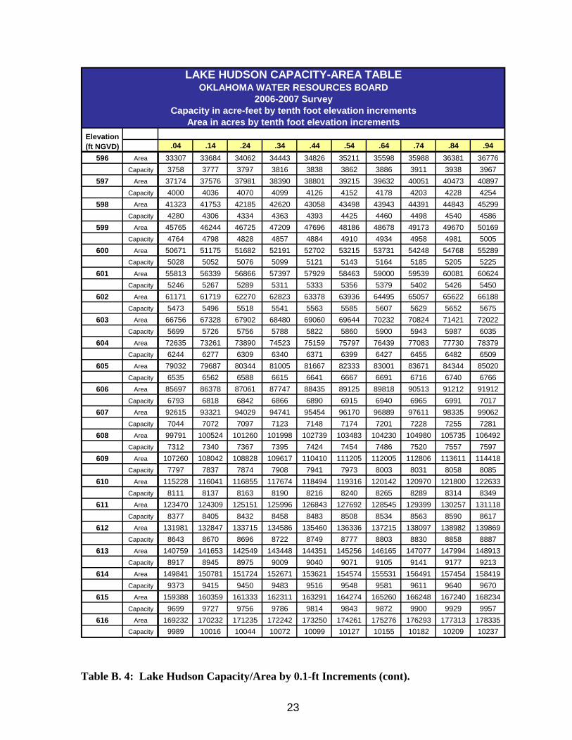
.04 .14 .24 .34 .44 .54 .64 .74 .84 .94596 Area 33307 33684 34062 34443 34826 35211 35598 35988 36381 36776
Capacity 3758 3777 3797 3816 3838 3862 3886 3911 3938 3967597 Area 37174 37576 37981 38390 38801 39215 39632 40051 40473 40897
Capacity 4000 4036 4070 4099 4126 4152 4178 4203 4228 4254598 Area 41323 41753 42185 42620 43058 43498 43943 44391 44843 45299
Capacity 4280 4306 4334 4363 4393 4425 4460 4498 4540 4586599 Area 45765 46244 46725 47209 47696 48186 48678 49173 49670 50169
Capacity 4764 4798 4828 4857 4884 4910 4934 4958 4981 5005600 Area 50671 51175 51682 52191 52702 53215 53731 54248 54768 55289
Capacity 5028 5052 5076 5099 5121 5143 5164 5185 5205 5225601 Area 55813 56339 56866 57397 57929 58463 59000 59539 60081 60624
Capacity 5246 5267 5289 5311 5333 5356 5379 5402 5426 5450602 Area 61171 61719 62270 62823 63378 63936 64495 65057 65622 66188
Capacity 5473 5496 5518 5541 5563 5585 5607 5629 5652 5675603 Area 66756 67328 67902 68480 69060 69644 70232 70824 71421 72022
Capacity 5699 5726 5756 5788 5822 5860 5900 5943 5987 6035604 Area 72635 73261 73890 74523 75159 75797 76439 77083 77730 78379
Capacity 6244 6277 6309 6340 6371 6399 6427 6455 6482 6509605 Area 79032 79687 80344 81005 81667 82333 83001 83671 84344 85020
Capacity 6535 6562 6588 6615 6641 6667 6691 6716 6740 6766606 Area 85697 86378 87061 87747 88435 89125 89818 90513 91212 91912
Capacity 6793 6818 6842 6866 6890 6915 6940 6965 6991 7017607 Area 92615 93321 94029 94741 95454 96170 96889 97611 98335 99062
Capacity 7044 7072 7097 7123 7148 7174 7201 7228 7255 7281608 Area 99791 100524 101260 101998 102739 103483 104230 104980 105735 106492
Capacity 7312 7340 7367 7395 7424 7454 7486 7520 7557 7597609 Area 107260 108042 108828 109617 110410 111205 112005 112806 113611 114418
Capacity 7797 7837 7874 7908 7941 7973 8003 8031 8058 8085610 Area 115228 116041 116855 117674 118494 119316 120142 120970 121800 122633
Capacity 8111 8137 8163 8190 8216 8240 8265 8289 8314 8349611 Area 123470 124309 125151 125996 126843 127692 128545 129399 130257 131118
Capacity 8377 8405 8432 8458 8483 8508 8534 8563 8590 8617612 Area 131981 132847 133715 134586 135460 136336 137215 138097 138982 139869
Capacity 8643 8670 8696 8722 8749 8777 8803 8830 8858 8887613 Area 140759 141653 142549 143448 144351 145256 146165 147077 147994 148913
Capacity 8917 8945 8975 9009 9040 9071 9105 9141 9177 9213614 Area 149841 150781 151724 152671 153621 154574 155531 156491 157454 158419
Capacity 9373 9415 9450 9483 9516 9548 9581 9611 9640 9670615 Area 159388 160359 161333 162311 163291 164274 165260 166248 167240 168234
Capacity 9699 9727 9756 9786 9814 9843 9872 9900 9929 9957616 Area 169232 170232 171235 172242 173250 174261 175276 176293 177313 178335
Capacity 9989 10016 10044 10072 10099 10127 10155 10182 10209 10237
Area in acres by tenth foot elevation incrementsElevation (ft NGVD)
LAKE HUDSON CAPACITY-AREA TABLEOKLAHOMA WATER RESOURCES BOARD
2006-2007 SurveyCapacity in acre-feet by tenth foot elevation increments
Table B. 4: Lake Hudson Capacity/Area by 0.1-ft Increments (cont).
24
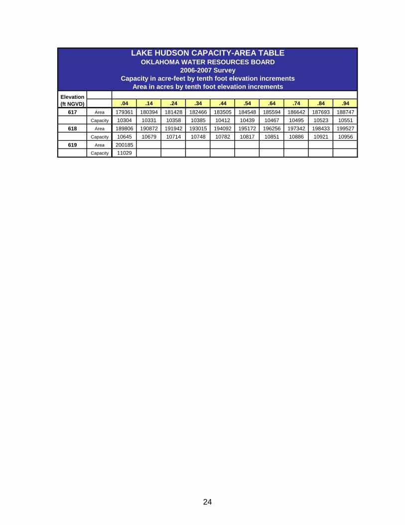
.04 .14 .24 .34 .44 .54 .64 .74 .84 .94617 Area 179361 180394 181428 182466 183505 184548 185594 186642 187693 188747
Capacity 10304 10331 10358 10385 10412 10439 10467 10495 10523 10551618 Area 189806 190872 191942 193015 194092 195172 196256 197342 198433 199527
Capacity 10645 10679 10714 10748 10782 10817 10851 10886 10921 10956619 Area 200185
Capacity 11029
LAKE HUDSON CAPACITY-AREA TABLE
Area in acres by tenth foot elevation incrementsElevation (ft NGVD)
OKLAHOMA WATER RESOURCES BOARD2006-2007 Survey
Capacity in acre-feet by tenth foot elevation increments
25
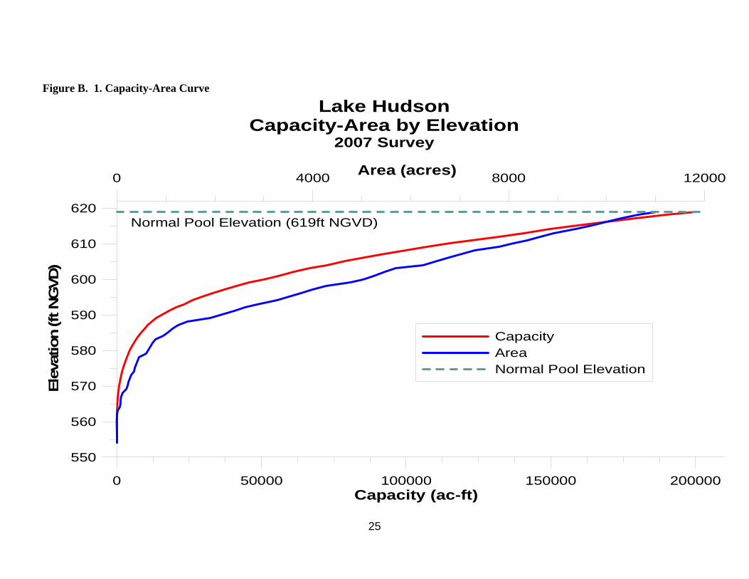
Figure B. 1. Capacity-Area Curve
0 4000 8000 12000Area (acres)
0 50000 100000 150000 200000Capacity (ac-ft)
550
560
570
580
590
600
610
620
Elev
atio
n (ft
NG
VD)
CapacityAreaNormal Pool Elevation
Lake HudsonCapacity-Area by Elevation
2007 Survey
Normal Pool Elevation (619ft NGVD)

26
APPENDIX C: Lake Hudson Bathymetric Maps

27
Figure C. 1: Lake Hudson Bathymetric Map with 5-foot Contour Intervals.

28
Figure C. 2: Lake Hudson Shaded Relief Bathymetric Map.

29
Figure C. 3: Lake Hudson Collected Data Points.