Embed Size (px)
Citation preview
HYDROGEOLOGIC CONDITIONS AND SALINE-WATER
INTRUSION, CAPE CORAL, FLORIDA, 1978-81
By Daniel J. Fitzpatrick
U.S. GEOLOGICAL SURVEY
Water-Resources Investigations Report 85-4231
Prepared in cooperation with the
CITY OF CAPE CORAL
Tallahassee, Florida
1986

UNITED STATES DEPARTMENT OF THE INTERIOR
DONALD PAUL HODEL, Secretary
GEOLOGICAL SURVEY
Dallas L. Peck, Director
For additional information write to:
District ChiefU.S. Geological SurveySuite 3015227 North Bronough StreetTallahassee, Florida 32301
Copies of the report can be purchased from:
Open-File Services Section Western Distribution Branch U.S. Geological Survey Box 25425, Federal Center Denver, Colorado 80225 (Telephone: (303) 236-7476)

CONTENTS
Page
Abstract 1In tr oduc tion 1
Description of area 2Acknowledgments 4
Hydrogeologic conditions 4Surficial aquifer system 4Intermediate aquifer system 11Floridan aquifer system 17
Saline-water intrusion in the upper limestone unit 19Downward intrusion ' 27Upward intrusion 29Lateral intrusion 30
Summary and conclusions 30Selected references 31
ILLUSTRATIONS
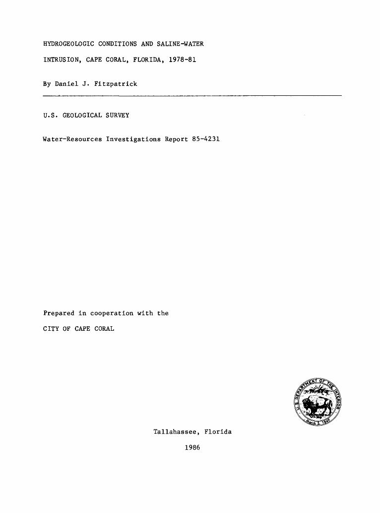
Figure 1. Map showing location of Cape Coral, Lee County 3
2. Generalized section showing geologic formations, lithology,and water-bearing units underlying Cape Coral 5
3. Map of Cape Coral showing generalized water-table contours of the surficial aquifer system near the end of the dry season, May 1980 7
4. Map of stoutheast corner of Cape Coral showing the densityof the canal system connected to tidewater 8
5. Graph showing relation between chloride concentration and specific conductance in water from the surficial aquifer system 9
6. Map showing location of salinity monitor wells withreference to a tidal canal 10
7. Map of Cape Coral showing chloride concentration in water from wells that tap the surficial aquifer system, May 1980 12
8. Hydrographs of water levels of the intermediate aquifer system in wells L-581 and L-1059 that tap the upper limestone unit of the Hawthorn Formation, and municipal pumpage from the upper limestone unit by Cape Coral, 1966-80 14
9. Map showing contours of the potentiometric surface of theintermediate aquifer system from wells that tap the upper limestone unit of the Hawthorn Formation, near the end of the wet season, September 1979 15
III

ILLUSTRATIONS Continued
Page
Figure 10. Map showing contours of the potentiometric surface of theintermediate aquifer system from wells that tap the upper limestone unit of the Hawthorn Formation, near the end of the dry season, May 1980 16
11. Map showing contours of the potentiometric surface of the Floridan aquifer system from wells that tap the lower limestone unit of the Hawthorn Formation, near the end of the dry season, May 1980 18
12. Map showing boundaries of insets A through F (figs. 13-18) and chloride concentration in water from wells tapping the upper limestone unit 20
13-18. Maps showing lines of equal chloride concentration in water from selected wells that tap the upper limestone unit in:
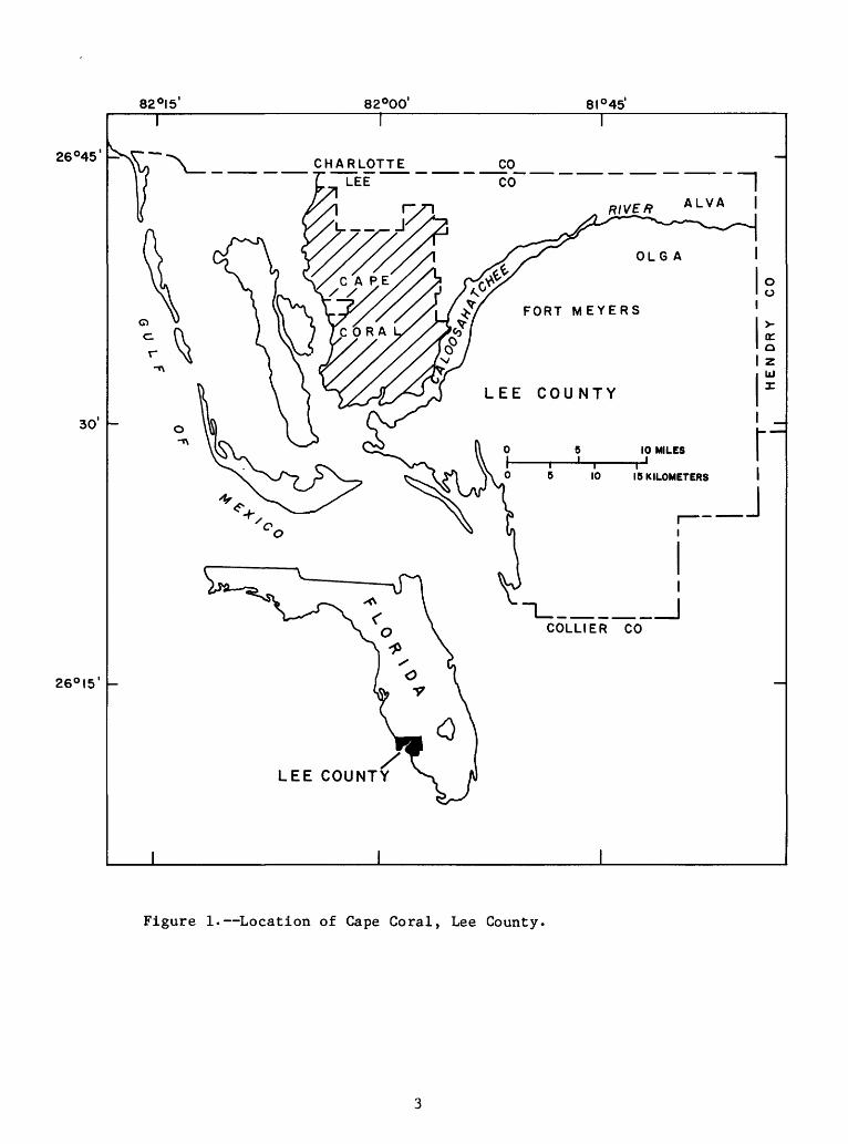
13. Inset area A (see fig. 12), 1979-81 2114. Inset area B (see fig. 12), 1979-81 2215. Inset area C (see fig. 12), 1979-81 2316. Inset area D (see fig. 12), 1979-81 2417. Inset area E (see fig. 12), 1979-81 2518. Inset area F (see fig. 12), 1979-81 26
19. Map showing areas of potential downward movement of water to the upper limestone unit of the Hawthorn Formation, May 1980 28
IV

HYDROGEOLOGIC CONDITIONS AND SALINE-WATER INTRUSION,
CAPE CORAL, FLORIDA, 1978-81
By Daniel J. Fitzpatrick
ABSTRACT
The principal source of freshwater for Cape Coral, Fla., is the upper limestone of the Hawthorn Formation, locally called the Hawthorn aquifer. This aquifer, which is within the intermediate aquifer system, has been con taminated by downward intrusion of saline water from the surficial aquifer system and by upward intrusion from the lower limestone of the Hawthorn Formation. The lower limestone is within the Floridan aquifer system and is under high artesian pressure. Much of the intrusion has occurred through open wellbores where steel casings are short or where casings have collapsed because of corrosion. Saline-water contamination of the upper limestone unit due to downward intrusion from the surficial aquifer system is most severe in the southern and eastern parts of Cape Coral; contamination due to upward intrusion has occurred in many areas throughout Cape Coral. Intrusion is amplified in areas of heavy water withdrawals and large water- level declines.
INTRODUCTION
The upper limestone unit of the intermediate aquifer system, locally referred to as the upper Hawthorn aquifer (in the upper part of the Hawthorn Formation) (Sproul and others, 1972), is the major source of freshwater for municipal and domestic supply and lawn irrigation for Cape Coral, Lee County, Fla. Over the years, problems resulting from development and utilization of ground water from this source have led to a deterioration in the water qual ity in some parts of the area, and to a potential for further deterioration in other parts. These problems, which relate to lack of detailed data in subsurface flow systems, have resulted in saline-water intrusion whereby: (1) wells were drilled to tap or penetrate not only the upper limestone unit but also hydraulically connect it to underlying or overlying limestones that contain saltwater, and (2) the head in the upper limestone unit at the well sites is below that in the hydraulically connected adjacent saltwater sources.
Between 1958 and 1975, nearly 8,000 2-inch steel-cased wells were drilled into the upper limestone unit in Cape Coral. Many of the wells also pene trated saline zones in the more shallow surficial aquifer system. With time, openings caused by corrosion of steel casings permitted downward leakage of saline water in areas where the head in the upper limestone unit had declined below that in the surficial aquifer system, and where the surficial aquifer

system contained saline water. Generally, prior to 1958, many flowing wells were constructed that tapped the deep saline aquifers for irrigation in the Cape Coral area. In many instances, these wells had short casings, allowing saline water from deep aquifers to flow freely into the upper limestone unit since the head in the deep aquifers is higher. Progressively larger areas have been affected by this process. This type of intrusion in Cape Coral and other areas of Lee County was first documented by Boggess and others (1977).
Increasing withdrawals from the upper limestone unit have caused a progressive decline and a widening of areas of lowered water levels, thereby increasing the potential for upward or downward saline-water intrusion as well as inland movement of saltwater from the Gulf of Mexico.
The declining water levels and saline-water intrusion led to an investi gation of the water resources of the area by the U.S. Geological Survey, in cooperation with the City of Cape Coral. The objectives of the study, which covers not only Cape Coral but also adjacent areas, were to: (1) further define the areal extent of saline-water intrusion in the upper limestone unit and the sources of the intrusion, (2) establish a network of wells to monitor water-quality and water-level changes in the upper limestone unit, and (3) obtain water-level and water-quality data in water-bearing units above and below the upper limestone unit. Between 1978 and 1981, an inventory of pri vately owned wells was made in the populated eastern and southern parts of Cape Coral. Most of the wells tapped the upper limestone unit. Water samples were collected and analyzed to determine salinity content. Nearly 1,300 wells were sampled.
Description of Area
The City of Cape Coral, in western Lee County (fig. 1), occupies an area of 110 mi ̂ between the Caloosahatchee River and bays of the Gulf of Mexico. The population of Cape Coral in 1984 exceeded 33,000, most of which was con centrated in the southern and eastern parts of the city.
Major development of the Cape Coral area began about 1958 with the con struction of an extensive 350-mile canal system. About 40 percent of the canals, those in the eastern and southern parts of the city, are affected by gulf tides. Weirs separate tidal (salty) reaches from nontidal (usually fresh) reaches. Throughout most of the canal system, water levels in the nontidal reaches are higher than those in the tidal reaches. The land sur face has been raised as much as 2 feet in some areas, using material dredged from canal construction.
The climate of the area is subtropical; temperature extremes are moder ated by the Gulf of Mexico. As reported by the National Oceanic and Atmos phere Administration, U.S. Department of Commerce, the average annual air temperature at Page Field in Fort Myers, 3.5 miles east of Cape Coral, is 74°F; monthly averages ranged from 83°F in August to 64°F in January. Rain fall is distributed unevenly throughout the year; more than 60 percent of the average annual rainfall (54 inches) occurs from June through September and results mostly from localized convective storms. Rainfall data from two sites in Cape Coral are given by Fitzpatrick (1982).
82°I5'
I
82°00' 8I°45'
26°45'
30
26°I5'
__iCOLLIER CO
LEE COUNTY
Figure 1. Location of Cape Coral, Lee County.

Acknowledgements
The author thanks the residents and city officials of Cape Coral for their cooperation and assistance during this investigation. This investiga tion initiated a continuing water-resources monitoring program in cooperation with officials of the City of Cape Coral, whose continued interest and support are greatly appreciated.
HYDROGEOLOGIC CONDITIONS
The upper 700 feet of sediments in the Cape Coral area comprise the Tampa Limestone and the Hawthorn Formation of Miocene age, the Tamiami Formation of Pliocene age, and the undifferentiated surface materials chiefly of Pleistocene and Holocene age (fig. 2). This section of sediments includes the following aquifer systems that yield water for public supply, irrigation, industrial, and domestic uses: The Floridan aquifer system, an intermediate aquifer system which includes an upper water-bearing limestone unit within the Hawthorn Formation, and the surficial aquifer system which includes the Tamiami Formation along with the blanketing undifferentiated younger materi als. The Floridan aquifer system, in general, yields nonpotable water in the Cape Coral area and will not be discussed as a usable source.
Chloride concentration of water is used in this report as an indicator of salinity. High chloride concentration is usually associated with high concentration of other salts or dissolved solids. Water with dissolved sol ids concentration more than 1,000 mg/L (milligrams per liter) is classified as saline (Krieger and others, 1957, p. 4).
Surficial Aquifer System^-/
The surficial aquifer system consists primarily of unconsolidated fine- to medium-grained quartz sand, interbedded sandy limestone and shell units, and gray or green sandy clay. The aquifer system generally ranges in thick ness from about 20 to 60 feet but locally may exceed 100 feet. A detailed description of the upper part of the surficial aquifer system is given in Boggess and others (1981). The surficial aquifer system is not used exten sively in Cape Coral; however, some wells, mainly in the northern part of the city, tap it for domestic use, and a small well field just east of the city taps it for public supply.
The Tamiami Formation, in the lower part of the surficial aquifer system, contains freshwater in central and eastern Lee County. Although it occurs in the eastern fringe of Cape Coral (Boggess and others, 1981), it is usually cased off in wells because it is composed of caving sand and sandy clay.
The water table in the unconfined surficial aquifer system is directly affected by rainfall. The water table declines in response to evapotranspi- ration and ground-water discharge into surface-water bodies. Other factors which can affect the water table include water discharging at land surface
"~ Deliberations among hydrogeologists active in southwest Florida that have .occurred since this report
was prepared and approved by the Director of the Geological Survey have resulted in placement of the re gional base of the surficial aquifer system higher in the hydrogeologic section than shown in this report.
Regionally, the base of the surficial aquifer system in southwest Florida is considered to be at the first areally persistent clay layer, which is commonly green and similar in lithology to the deeper lying clays
of the Hawthorn Formation. In the Lee County area, the first clay is thin and affords seeming hydrologic
continuity between the water table and the "sandstone aquifer," as evidenced by the similar configuration
of the potentiometric surface of the "sandstone aquifer" with that of the water table. Therefore, on the basis of local data, this report regards the "sandstone aquifer" as part of the surficial aquifer system rather than as part of the intermediate aquifer system, which is the consensus recently arrived at based on regional considerations.

DEPTH (feet)
100
200-
300-
400-
500
600-
700-
800
SERIES
HOLOCENEAND PLEISTOCENE
PLIOCENE
MIOCENE
OLIGOCENE
FORMATION
UNDIFFERENTIATED DEPOSIT
TAMIAMI FORMATION
HAWTHORN FORMATION
TAMPA LIMESTONE
SUWANNEE LIMESTONE
LITHOLOGY
SAND FOSSILIFEROUSLIMESTONE.WHITE TO YELLOW.^ SANDY, MARLY, FOSSILIFEROUS
CLAY,CALCAREOUS,GREEN
SANDS SANDSTONE, GR AY, CALCAREOUS ,
CLAY.GRAY.SANDY.PHOSPHATIC/
LIMESTONE, GRAY-WHITE, CHALKY, SANDY, PHOSPHATIC
CLAY S MARL .GRAY AND GREEN, SOME LIMESTONE
LIMESTONE, GRAY-WHITE SANDY, PHOSPHATIC
LIMESTONE, GRAY 8TAN, SLIGHTLY PHOSPHATIC
LIMESTONE, TAN, MODULAR
WATER-BEARING UNITS
SURFICIALAQUIFER SYSTEM
J
J
''IfINTERMEDIATE AQUIFER * SYSTEM
UJh- co
Lower £rlimestone Unit
UJu.5Or
Z
OE0
Figure 2. Geologic formations, lithology, and water-bearing unitsunderlying Cape Coral.

from wells tapping deeper aquifers, downward leakage, and tidal fluctuations in areas adjacent to the Gulf of Mexico and tidal canals. The water table in the Cape Coral area is generally highest during the wet season (June to Sep tember) and lowest at the end of the dry season (April or May) (Fitzpatrick, 1982, figs. 6-17). Fluctuations are generally 1 to 2 feet.
The water-table contours in figure 3 represent low water conditions near the end of the dry season (May 1980). As shown, water levels were highest in the northeastern part of Cape Coral and lowest along the coastal zone, which is dissected by canals. The extreme density of canals is indicated in fig ure 4, which represents the southeast corner of Cape Coral. These coastal canals, which are not controlled in lower reaches, are affected by tides and normally contain highly saline water which enhances the possibility of salt water intrusion. The canals are equipped with weirs along inland reaches to retard overdrainage of ground water and to block the upstream flow of sea- water. Thus, water levels higher than tide levels are maintained upstream of the weirs. Weir locations and crest elevations are shown in figure 3. The contours in figure 3 are highly generalized.
Water quality in the surficial aquifer system is variable. Chloride concentrations range from about 10 to 20,000 mg/L. Areas that contain highly saline water are significant because of their potential as sources of saline- water contamination by downward leakage to the intermediate aquifer system. The existence of saline water in the surficial aquifer system depends largely on proximity to the Caloosahatehee River, the Gulf of Mexico, and tidal reaches of the coastal canal system. Although water quality of the canal system has not been extensively monitored, highly saline water can be ex pected in canals open to the gulf and the river, particularly during the dry months. Sections of canals inland of the weirs, although not open to tidewater, may still contain saline water when insufficient head exists to counter the inland migration of saline water.
An example of the extent of intrusion of saline water from a canal into a line of wells penetrating surficial material is shown in the following table:
SpecificSource Distance from conductance
canal (feet) (micromhos/cm)
CanalWell L-2286Well L-2287Well L-2288
_60
120180
30,00028,20027,300
1,380
Specific conductance, an indicator of chloride concentration (fig. 5), was measured in a tidal canal and in wells that tap the surficial aquifer system at different distances from the canal (fig. 6). A slight decrease in specific conductance is evident in the well up to 120 feet from the canal. However, at a 180-foot distance, the specific conductance in a well decreased

05' 55'
2 .4^ jTRQfigANA PKWY
3.49
EXPLANATION 2.84
WELL LOCATION AND WATER LEVEL,IN FEET ABOVE SEA LEVEL.
S~~" CONTOUR OF WATER TABLE IN FEET ABOVE SEA LEVEL;INTERVAL 5 FEET;DASHED WHERE! APPROXIMATE.
±3.5CANAL SALINE CONTROL STRUCTURE(WEIR),AND CREST ALTITUDE, IN FEET ABOVE SEA LEVEL
6 KILOMETERS \Figure 3. Cape Coral showing generalized water-table contours of the surficial
aquifer system near the end of the dry season, May 1980.

81° 57*
26°34'
26°33'
CAPE COBAL BRIDGE PARKWAY
2000 FEET
500 METERSREDFISH POINT
Figure 4. Southeast corner of Cape Coral showing the density of the canalsystem connected to tidewater.

100 1000 10,000
SPECIFIC CONDUCTANCE,MICROMHOS/CM AT 25°C
100,000
Figure 5. Relation between chloride concentration and specific conductance inwater from the surficial aquifer system.

81° 58'25"\____
26° 35' -
26° 34' 56" -
81° 58'15'
L- 2287
L-228
L-2288
L^ SE 37 TH TER
< o
< o
EXPLANATION
L-2287 WELL LOCATION AND NUMBER
300 600 i
100 200
900 FEETH
METERS
Figure 6. Location of salinity monitor wells with reference to a tidal canal
10

to less than 5 percent of that in the canal. The distance that saline water will intrude into the surficial aquifer system is governed largely by the hydraulic conductivity of the aquifer matrix and by the freshwater head main tained above sea level.
Chloride concentrations in water from selected wells that tap the sur ficial aquifer system were determined in May 1980 (fig. 7). These data and data obtained earlier by Boggess and others (1977, p. 24-25) were used to examine the occurrence of saline water in the surficial aquifer system. Although the data points are insufficient to define the full distribution of saline water, the following generalities can be made:
1. The most widespread occurrence of saline water in the surficial material is where the coastal zone is most dissected by tidal canals specifically the areas south of Everest Parkway and east of Del Prado Boulevard, and the area south of Cape Coral Parkway and east of Chiquita Boulevard (fig. 3). Chloride concentrations range from 740 to more than than 26,000 mg/L. For comparison, seawater contains about 19,000 mg/L of chloride.
2. In the remaining area of tidal canals (fig. 7), the occurrence of saline water in the shallow ground water is not widespread. Saline water is probably limited to those parts of the surficial aquifer system immediately adjacent to the tidal canals.
3. Analyses of water from wells in the area west of Chiquita Boulevard indicate saline water in parts of the surficial aquifer system. This area is also highly dissected by canals which, although not directly open to major tidal water bodies, probably became saline by lateral subsurface migration.
Intermediate Aquifer System
The intermediate aquifer system is heavily utilized in the Cape Coral area for both municipal supplies and individual residential purposes. It is composed of an upper limestone unit and a section of clay and marl of low permeability, as much as 150 feet thick, which effectively confines a limestone unit in the upper part of the Floridan aquifer system (fig. 2). Casings of wells tapping the intermediate aquifer system range in length from about 120 to 150 feet.
The upper limestone unit of the intermediate aquifer system consists predominantly of sandy, phosphatic limestone. It was described in detail by Boggess (1981) who referred to this unit as the upper Hawthorn aquifer (in the upper part of the Hawthorn Formation). It ranges in thickness from about 50 to 150 feet and is the major source of freshwater for Cape Coral and sur rounding areas. More than 10,000 privately owned wells have been drilled to the upper limestone unit since development began in Cape Coral. About 8,000 wells are of small-diameter steel casings which were installed before a 1975 local ordinance was passed requiring the use of nonmetallic casing.
11

82° 10' 05
26°45'
40'
35'
26° 30'
82°00'
CTTAIRLOTTE COUNTY
82°55'
LEECOUNTY-4-
////// // / rr
EXPLANATION
SURFICIAL AQUIFER WELL LOCATION, WELL MUM BE R(L-3243) AND CHLORIDE CONCENTRATIONS (50)IN MILLIGRAMS PER LITER.
APPOXIMATE WESTERLY BOUNDARY OF AREA CONTAINING TIDAL CANALS.
\s-p If3252~
5100
4 MILES
024 6 KILOMETERS
Figure 7. Cape Coral showing chloride concentration in water from wells that tap the surficial aquifer system, May 1980.
12

The upper limestone unit is under artesian pressure so that the water level in wells tapping it rises above the top of the limestone. Increasing withdrawals for both municipal and domestic uses have resulted in a general downward trend in water levels in some areas. The effect of withdrawals on water levels in wells is illustrated in figure 8. The increase in municipal pumpage resulted in a corresponding decrease in water levels in well L-581, in south-central Cape Coral, from 1966 to 1977. Withdrawals from the upper limestone unit were reduced in 1977 when a reverse osmosis plant began pro ducing potable water from saline water withdrawn from wells in the limestone unit of the Floridan aquifer system. This reduction is reflected in a short- interval rise in water levels in well L-581 followed by a resumption in decline in 1979. In contrast, a hydrograph of well L-1059 (fig. 8), in the northwestern part of Cape Coral, illustrates water-level fluctuations in an area relatively unaffected by withdrawals. Although water levels in well L-1059 indicate seasonal fluctuations, no downward trend occurred. Effects of pumping on water-level fluctuations in wells in the upper limestone unit in other areas of Cape Coral are illustrated by Fitzpatrick (1982).
Most recharge to the upper limestone unit occurs north and northeast of Lee County where the limestone is probably hydraulically connected with the surficial aquifer system. Beneath Cape Coral, some recharge probably occurs from upward or downward leakage through the confining beds in areas wherethe artesian pressure in the upper limestone unit has been lowered by pumping (Boggess and others, 1981).
Areawide water levels in wells in the upper limestone unit are illus trated by contours of the potentiometric surface in figures 9 and 10. The potentiometric surface is defined by Lohman and others (1972) as the level to which water will rise in a tightly cased well, and is a surface which represents the static head in the aquifer. Contours of the potentiometric surface representing high water levels are based on data collected in Sep tember 1979 (fig. 9), and contours representing low water levels are based on data collected in May 1980 (fig. 10).
The major areas of withdrawal for public water supply are immediately apparent in figures 9 and 10 by drawdowns of water level in central Cape Coral and in the area southeast of Cape Coral, east of the Caloosahatchee River. The coalescing of the cones of depression around both of these well fields probably affects the potential well-field production of each. Three smaller areas of withdrawal for public supply (figs. 9 and 10) also exist in Cape Coral and adjacent areas, but the drawdowns caused by these withdrawals are localized and not so prominent. Ground-water flow within the upper lime stone unit is generally toward the centers of the two major withdrawal areas. The regional hydraulic gradient within this part of Lee County, however, is to the southwest.
Differences in water quality in the upper limestone unit generally reflect the varying degrees of saline-water intrusion that have occurred. Chloride concentrations generally range from about 40 to 100 mg/L in areas relatively unaffected by intrusion; chloride concentrations of several thousand milligrams per liter occur in severely affected areas. An example of the water-quality variations in Cape Coral is shown in Fitzpatrick (1982,
13

UJ CO
o
20
15
10
5303 Oz SEA < LEVELUJ
i 510
15
20
UJ UJu.
UJ>UJ
OC.
UJ
^ 30
35
10
20
P 3°
=! 5 40 2 ui
1 T
WELL L-1059
I ML*.* -
WELL L^ 581 '
I I I I I III I I I I I
Ifj 50So
60
70
80
r
1966 67 68 69 70 71 72 73 74 75 76 77 78 79 80 81
Figure 8. Water levels of the intermediate aquifer system in wells L-581 and L-1059 that tap the upper limestone unit of the Hawthorn Formation, and municipal pumpage from the upper limestone unit by Cape Coral, 1966-80,
14

82»IO' 1*50'
EXPLANATION 728
I WELL LOCATION AND WATER LEVEL ABOVE AND BELOW(-) SEA LEVEL,IN FEET.
/O -^WATER-LEVEL CONTOUR SHOWING ALTITUDE OF THE POTENTIOMETRIC SURFACE. INTERVAL IS 10FEET. DATUM IS SEA LEVEL. DASHED WHERE APPROXIMATE.
WLOCATION OF MUNICIPAL WELL FIELD.
I6 KILOMETERS
86* 30'
Figure 9. Contours of the potentiometric surface of the intermediate aquifer system from wells that tap the upper limestone unit of the Hawthorn Formation, near the end of the wet season, September 1979.
15

2° 10' 05' 82eOO' 55' 81° 50'
26°45'
90'
M»IO'
EXPLANATION 11.16
WELL LOCATION AND WATER LEVEL ABOVE AND BELOWHSEA LEVEL IN FEET.
WATER-LEVEL CONTOUR SHOWING ALTITUDE OF THE POTENTIOMETRIC SURFACE. INTERVAL IS 10 FEET. DATUM IS SEA LEVEL. DASHED WHERE APPROXIMATE.
wLOCATION OF MUNICIPAL
L.WELL FIELD.
\
Figure 10. Contours of the potentiometric surface of the intermediate aquifer system from wells that tap the upper limestone unit of the Hawthorn Formation, near the end of the dry season, May 1980.
16

table 5), which gives the major chemical constituents observed in water from monitor wells in Cape Coral and adjacent areas. In 1980, chloride and dis solved solids concentrations from these wells ranged from a low of 52 and 302 mg/L to a high of 1,100 and 2,340 mg/L. Concentrations of most other major constituents varied proportionately. Although these data do not re flect the total range of constituent concentrations, they do indicate the wide variations in water quality.
Floridan Aquifer System
Relatively few wells tap the Floridan aquifer system in the Cape Coral area. These wells withdraw water from the lower limestone unit of the Hawthorn Formation that underlies the thick clay and marl confining material of the intermediate aquifer system. The lower limestone unit consists pre dominantly of sandy limestone but also contains phosphorite. During early years of development of the area, wells were drilled to one or both of these limestone units of the Hawthorn Formation for irrigation because such wells will flow at the land surface and yield great quantities. A few wells pos sibly penetrated deeper limestones of the Floridan aquifer system, 750 to 800 feet deep, to obtain maximum yield. Casing in the wells was generally to the top of the upper limestone unit, leaving the wellbore open for interflow among the artesian limestones under differing heads. The number of these ir rigation wells is not known; most are no longer used, some have been plugged, and others probably were capped and abandoned. Wells in the limestone of the Floridan aquifer system supply the saline water used in the reverse osmosis conversion system for the Cape Coral municipal supply.
Artesian pressures in the Floridan aquifer system are sufficient to sus tain flow at land surface throughout Cape Coral and Lee County, except in a few localized areas of heavy withdrawals. In general, the artesian pressure is greater than that in the upper limestone unit of the intermediate aquifer system because of the greater withdrawals from the upper limestone unit. Water-level fluctuations in wells in the Floridan aquifer system are princi pally the result of withdrawal. Fitzpatrick (1982, fig. 4) showed a decline of about 15 feet in 3 years in an observation well near the reverse osmosis plant as a result of heavy withdrawals. Water levels in areas relatively unaffected by pumping generally vary 3 or 4 feet seasonally, as shown by Fitzpatrick (1982, figs. 18 and 19).
Areal variations of the potentiometric surface of the Floridan aquifer system in the Cape Coral area during May 1980 are shown in figure 11. The contours indicate a hydraulic gradient to the southwest. Healy (1962) showed an increase in the artesian head northward from Lee County, suggesting that recharge occurs there. The northeastward shift in the 30- and 40-foot con tours (fig. 11) denotes a decrease in artesian pressure and is probably the result of discharge and leakage from the numerous artesian wells along the Caloosahatchee River (Boggess, 1974).
The Floridan aquifer system beneath Cape Coral generally contains waterof varying degrees of salinity. Concentrations in water from monitor wellsin Cape Coral and adjacent areas range from 400 to 1,900 mg/L for chloride
17

05' 82°00' 55' W«50'
26°45'
40'
35' PINE ISLAND
WELL LOCATION AND WATER LEVEL,IN FEET ABOVESEA LEVEL.
WATER LEVEL CONTOUR SHOWING ALTITUDE OF THE POTENTIOME.TRIC SURFACE. INTERVAL IS 10 FEET DATUM IS SEA LEVEL
41'
KILOMETERS
Figure 11. Contours of the potentiometric surface of the Floridan aquifer system from wells that tap the lower limestone unit of the Hawthorn Formation, near the end of the dry season, May 1980.
18

and from 1,190 to 4,230 mg/L for dissolved solids (Fitzpatrick, 1982, table 7). Chloride data from Boggess (1974) showed concentrations ranging between 500 and 1,000 mg/L and a maximum of 2,380 mg/L in wells in the Cape Coral area that tap one or both units. Variations in the water quality can be attributed to the well locations, differences in length and depth of open borehole intervals, and differences in the rate of contribution of flow from the Floridan aquifer system.
SALINE-WATER INTRUSION IN THE UPPER LIMESTONE UNIT
Progressively larger segments of the upper limestone unit have been con taminated with saline water due to downward, upward, and lateral intrusion. A prime indicator of saline-water intrusion is chloride concentration in wells. Chloride concentrations in selected wells tapping the upper limestone unit, sampled during 1978-80, are shown in figure 12. Where intrusion has not occurred, chloride concentrations range from about 40 to 100 mg/L. Greater concentrations of chloride generally indicate saline-water intrusion. In much of the area unaffected by saline-water contamination, the potential exists for intrusion through lateral movement of saline water from areas of contamination, or through upward or downward movement from saline units.
Areas where intrusion is known to have occurred are circumscribed in figure 12, and the distributions of chlorides are delineated, by area, by lines of equal chloride concentration, in figures 13 to 18. These lines generally encircle an intrusion source within which chloride concentration decreases with distance outward from that source. Thus, certain determin ations and inferences can be made regarding the intrusion source and its effect on the water quality in the upper limestone unit including: (1) ap proximate location of the intrusion source, (2) extent of contamination in the upper limestone unit related to the intrusion source, and (3) direction of the saline-water movement from the source.
In places, upward or downward intrusion can be identified by the dispo sition of lines of equal chloride concentration around a source. Individual areas contaminated by deep wells through upward intrusion generally are more widespread than those contaminated by individual wells through downward intrusion. This is because many of the wells that tap the lower limestone unit are used for irrigation, are more than 40 years old, and because upward flow of saline water was unobstructed through the uncased section of the wells. Also, the hydraulic gradient between the Floridan unit and the inter mediate unit is usually greater than that between the upper limestone unit and the surficial aquifer system. In some places, relatively large areas of the upper limestone unit are affected by downward intrusion of saline water due to many contaminating wells simultaneously leaking saline water. The source of intrusion can also frequently be defined by maximum chloride con centrations in an area of contamination. Wells tapping the upper limestone unit in areas where downward intrusion has occurred, commonly contain chlo ride concentrations of several thousand milligrams per liter. In areas where upward intrusion has occurred, the maximum chloride concentrations would not exceed levels in the deeper producing units, generally ranging between 500 and 1,000 mg/L.
19

82° 10' 05' 82°00' 55
26°45'
~l T" CHARLOTTE COUNTYi*EXPLANATION
WELL FIELD
L-1058 WELL LOCATION.WELL NUMBER
LEE COUNTY
L-1059 400
40
35
26°30'
400 (L- O58), AND CHLORIDE CONCENTRATION (400)IN MILLIGRAMS PER LITER.
[A] AREA OF'INTRUSION WHERE LINES OF EQUAL CHLORIDE ARE MAPPED.
L-IIIO 420
I75 L-1109
165TROPICANA PKWY
L-2644 900
L-1247 325 *.
CAPE CORAL
4 MILES
1 6KILOMFTERS
Figure 12. Boundaries of insets A through F (figs. 13-18) and chloride concentration in water from wells tapping the upper limestone unit.
20

81
° 58
'
\
I_______P
QN
DE
LL
A
RO
AD
EX
PL
AN
AT
ION
WE
LL
L
OC
AT
ION
.
10
0
LIN
E
OF
EQ
UA
L C
HL
OR
IDE
C
ON
CE
NT
RA
TIO
N.
DA
SH
ED
WH
ER
E
AP
PR
OX
IMA
TE
LY
LO
CA
TED
. IN
TE
RV
AL
S A
RE
10
0 A
ND
2
00
M
ILL
IGR
AM
S
PE
R
LIT
ER
Figu
re 13.--Lines of equal
chloride concentration in
upper limestone unit in
in
set
area Awater from selected wells th
at ta
p the
(see
fig. 12
), 1979-81.

8I°
57
'
26°
38'
SE
16
th
TE
RR
AC
E
EX
PL
AN
AT
ION
WE
LL
L
OC
AT
ION
LIN
E
OF
EQ
UA
L C
HL
OR
IDE
C
ON
CE
NT
RA
TIO
N. D
AS
HE
D W
HE
RE
A
PP
RO
XIM
AT
EL
Y
LO
CA
TE
D.
INT
ER
VA
LS
A
RE
10
0 A
ND
2
00
M
ILL
IGR
AM
S
PE
R
LIT
ER
Figure 14.--Lines of equal chloride concentration in water from selected wells that ta
p the
upper limestone unit in inset area B
(see
fig. 12), 1979-81.

8I°
57'
N>
U3
26e3
6'
EVER
EST
PARK
WAY
NW
AL
IS
PA
RK
WA
Y
LIN
E
OF
EQ
UA
L
CH
LO
RID
E
CO
NC
EN
TR
AT
ION
.--D
AS
HE
D W
HE
RE
A
PP
RO
XIM
AT
EL
Y
LO
CA
TE
D.
INT
ER
VA
LS
A
RE
10
0 A
ND
2
00
M
ILL
IGR
AM
S
PE
R
LIT
ER
Figure 15.--Lines of equal chloride concentration in water from selected wells that tap the
upper limestone unit in inset area C
(see
fi
g. 12), 1979-81.

8I°
57
'
26°3
4'
DO
RA
DO
tf
AR
KW
AY
EX
PL
AN
AT
ION
LIN
E
OF
EQ
UA
L
CH
LO
RID
E
CO
NC
EN
TR
AT
ION
.--D
AS
HE
D W
HE
RE
A
PP
RO
XIM
AT
EL
Y
LO
CA
TE
D.
INT
ER
VA
LS
A
RE
10
0 A
ND
2
00
M
ILL
IGR
AM
S
PE
R
LIT
ER
Figure 16. Lines of eq
ual
chloride in
water
from selected wells th
at tap
the
upper
lime
stone
unit in in
set
area D
(see
fig. 12),
1979-81.
82
°00
'8
I°5
9'
8I°
58'
26° 34
' -
CA
PE
C
OR
AL
B
RID
GE
P
AR
KW
AY
EX
PL
AN
AT
ION
WE
LL
L
OC
AT
ION
.
LIN
E
OF
EQ
UA
L
CH
LO
RID
E
CO
NC
EN
TR
AT
ION
.--D
AS
HE
D W
HE
RE
A
PP
RO
XIM
AT
EL
Y
LO
CA
TE
D.
INT
ER
VA
LS
A
RE
10
0 A
ND
200
MIL
LIG
RA
MS
P
ER
L
ITE
R
26°33' -
Figure 17.--Lines of equal chloride concentration in water from selected wells that ta
p the
upper limestone unit in inset area E
(see
fi
g. 12
), 1979-81.

K>
26°3
5'
LIN
E
OF
EQ
UA
L
CH
LO
RID
E
CO
NC
EN
TR
AT
ION
. D
AS
HE
D W
HE
RE
A
PP
RO
XIM
AT
EL
Y
LO
CA
TE
D.
INT
ER
VA
LS
A
RE
10
0 A
ND
2
00
M
ILL
IGR
AM
S
PE
R
LIT
ER
BR
IDG
E \
JA
RK
WA
Y
Figure 18.--Lines of equal chloride concentration in water from selected wells that ta
p the
upper limestone unit in
in
set
area F
(see
fig. 12), 1979-81.

Downward Intrusion
The downward movement of highly saline water from the contaminated coastal sectors of the surficial aquifer system to the upper limestone unit is usually through corroded openings in steel well casings or short well casing installations. It has occurred in areas of Cape Coral where: (1) the surficial aquifer system contains saline water, and (2) the hydraulic gradi ent between the two horizons is downward. The mechanism of downward intru sion related to well casing installation is explained in detail by Boggess and others (1977). Where these conditions are met, leakage of saline water may also occur through the confining layer above the upper limestone unit; however, leakage probably would be at a low rate.
The combined conditions necessary for downward intrusion of saline water do not exist throughout the Cape Coral area. In those areas where the arte sian pressure is relatively unaffected by withdrawals, the potentiometric surface in the upper limestone unit is higher than that in the surficial aquifer system, and movement would be upward toward the surficial material. Also, the occurrence of saline water in the surficial aquifer system is not widespread but usually occurs in those areas adjacent to tidal water bodies.
Comparison of the potentiometric surfaces (figs. 3 and 10) indicates areas where the water levels in the surficial aquifer system are higher than those in the upper limestone unit. The shaded area in figure 19 approximates that part of Cape Coral where the hydraulic gradient was downward during the low water conditions of May 1980. The areal extent where this condition ex ists fluctuates along the northern and western fringes, primarily in response to seasonal changes in withdrawals from the upper limestone unit.
In parts of this area of potential downward movement, highly saline water occurs in the surficial aquifer system. These areas are south of Everest Parkway and east of Del Prado Boulevard, as denoted by the hachured pattern in figure 19. The occurrence of saline water in the remaining area of downward gradient is limited to those parts of the surficial aquifer system adjacent to tidal canals. Variations in salinity within the saline part of the surficial materials and the amount of head difference between the surficial aquifer system and the intermediate aquifer system influence the potential impact on the intermediate aquifer system.
Effects of downward intrusion are most severe in those areas with the highest potential; that is, south of Everest Parkway and east of Del Prado Boulevard (fig. 15) and in areas south of Cape Coral Parkway (fig. 16). Downward intrusion through wells within these areas was first documented by Boggess and others (1977, p. 22-27). Chloride concentrations of several thousand milligrams per liter were noted in two localized areas of the upper limestone unit within this boundary.
Downward intrusion east of Del Prado Boulevard (fig. 15) is a result of leakage from several wells. Smaller areas of intrusion west of Del Prado Boulevard are also evident (fig. 15), which may be due to upward or downward intrusion.
27

82°IO'
26*48'
LEE COUNTY
APPROXIMATE AREA WHERE THE HYDRAULIC GRADIENT IS DOWNWARD FROM THE SURFI- CIAL AQUIFER SYSTEM.
AREA WHERE SURFICIAL
AQUIFER SYSTEM CONTAINS SALINE WATER,AND APPROX (MATE AREA WHERE PON- TENTIAL FOR DOWNWARD INTRUSION IS WIDESPREAD
INLAND BOUNDARY OF AREA WHERE CANALS ARE AFFECTEd BY TIDES.
6 KILOMETERS
26«30'
Figure 19.--Areas of potential downward movement of water to the upper limestone unit of the Hawthorn Formation, May 1980.
28

Downward intrusion south of Cape Coral Parkway (figs. 16, 17) is less widespread than it is east of Del Prado Boulevard. This may be due to smaller differences in hydraulic gradient. In both areas where downward intrusion has occurred, many contaminating wells have been plugged; however, the potential for further downward intrusion probably persists.
Contamination through downward intrusion has also occurred just east of Santa Barbara Boulevard (fig. 18). Wells in this area were sampled before 1976, and chloride concentrations were as high as 9,975 mg/L. Many of the wells sampled then were plugged and could not be resampled.
Upward Intrusion
The upward movement of saline water from the Floridan aquifer system to the upper limestone unit has occurred throughout Cape Coral through the open bore in wells that tap both limestone units. The potential exists for upward intrusion along open bore holes in wells where the Floridan aquifer system contains saline water, and its potentiometric surface is higher than that of the upper limestone unit. The mechanics of upward intrusion was explained in detail by Boggess and others (1977). The required hydrologic conditions for upward intrusion generally exist throughout the Cape Coral area. The poten tiometric surface of the Floridan aquifer system is generally at least 20 to 25 feet higher than that in the upper limestone unit. Furthermore, saline water occurs throughout the Floridan aquifer system beneath Cape Coral. Some direct upward leakage of saline water probably occurs through the intervening confining layer. However, this leakage would be at a very low rate and would not be expected to have a significant impact.
Two, and possibly three, areas of upward intrusion from point sources are apparent in figure 13. The areas are relatively large; the maximum chlo ride concentrations are equivalent to those in wells that tap the Floridan aquifer system, and their locations are distant from areas where the poten tial for downward intrusion is likely (fig. 19).
The high chloride concentration in the western part of the area shown in figure 14 is probably a result of upward intrusion. Although this area is generally where there is potential for downward intrusion, the extent of the contamination is relatively widespread, and the maximum chloride concentra tions are within the general range of those in the deeper unit. Some lateral movement of saline water toward the east seems to have occurred.
Contamination in the upper limestone unit in the vicinity of Mohawk Parkway (fig. 18) is also probably due to upward intrusion. Potentially, contamination could be by downward intrusion, but the widespread nature of the intrusion suggests that the source is from below.
High chloride concentrations in some parts of Cape Coral, north of State Road 78 (fig. 12), probably indicate additional areas where the upper lime stone unit has been affected by upward intrusion. The areal extent of the saline-water contamination is not defined there. Wells sampled in the western part of Cape Coral (fig. 12) contain high chloride concentrations relative to
29

unaffected areas in other parts of the city. These high concentrations may, in part, reflect residual seawater from earlier inundations that was not flushed through natural processes over the years.
Lateral Intrusion
Lateral intrusion of saline water into the upper limestone unit of the intermediate aquifer system begins at a contaminating well. Saline water moves out laterally in the permeable aquifer materials, affecting a progres sively larger area. Salinity levels are highest adjacent to the contamina ting well and decrease with distance from the well. The rate of lateral movement depends largely upon the hydraulic conductivity of the aquifer and the prevailing hydraulic gradient at the contaminating source. Lateral movement is generally not radially symmetrical but, rather, exhibits certain directional preferences.
Potentially, the most severe impact on water quality in the upper lime stone unit would be inland movement of seawater, assuming hydraulic connec tion exists offshore between the upper limestone unit and the Gulf of Mexico. Inland movement would occur if a reversal side of the seaward hydraulic gradient, caused by increased withdrawals, was to extend outward to intersect the area of offshore connection. The potential for inland movement increases as artesian levels decline.
SUMMARY AND CONCLUSIONS
The upper limestone unit of the Hawthorn Formation, the freshwater bearing unit of the intermediate aquifer system, is the principal source of municipal supply for Cape Coral. Many parts of the upper limestone unit no longer contain potable water. Short casings in wells, corroded iron casings, and declining water levels are major problems causing the deterioration of water quality. Although contamination due to well casing problems poses an immediate threat to the freshwater source, the potential for severe long- range impact on the water quality is the inland movement of saltwater along the coastal area. The probability for inland movement increases as water levels progressively decline.
Short casings or corroded casings in wells permit: (1) saline water from the surficial aquifer system to leak downward to the upper limestone unit, and (2) saline water from the lower limestone unit of the Hawthorn Formation, part of the Floridan aquifer system, to move upward into the upper freshwater source under high pressure. A progressive decline in water levels in the upper limestone unit due to increased withdrawals has enhanced the potential for upward or downward intrusion.
The potential areas for downward intrusion are near saline (tidal) surface-water bodies and are predominantly east of Del Prado Boulevard, south of Everest Parkway, and south of Cape Coral Parkway. The potential also exists to the west and north. The potential for upward intrusion exists throughout the Cape Coral area. Downward intrusion has principally occurred
30

south of Everest Parkway and east of Del Prado Boulevard, and south of Cape Coral Parkway where the highest potential for intrusion exists. Significant downward intrusion has also occurred just east of Santa Barbara Boulevard. A third type of intrusion moves out laterally from the problem well, expand ing the contaminated area as dictated by hydraulic gradient and preferred paths of permeability of sediments.
SELECTED REFERENCES
Boggess, D. H. , 1974, Saline ground-water resources of Lee County, Florida: U.S. Geological Survey open-file report FL-74-247, 62 p.
Boggess, D. H., Missimer, T. M., and 0'Donnell, T. H., 1977, Saline-water intrusion related to well construction in Lee County, Florida: U.S. Geological Survey Water-Resources Investigations 77-33, 29 p.
1981, Hydrogeologic sections through Lee County and adjacent areas of Hendry and Collier Counties, Florida: U.S. Geological Survey Water- Resources Investigations Open-File Report 81-638.
Fitzpatrick, D. J. , 1982, Water-resources data of the Cape Coral area, Lee County, Florida: U.S. Geological Survey Open-File Report 82-772, 48 p.
Healy, H. G. , 1975, Piezometric surface and areas of artesian flow of theFloridan aquifer in Florida, July 6-17, 1961 (2nd ed.): Florida Bureau of Geology Map Series 4.
Krieger, R. A., Hatchett, J. L., and Poole, J. L., 1957, Preliminary survey of the saline-water resources of the United States: U.S. Geological Survey Water-Supply Paper 1374, 172 p.
Lohman, S. W., 1972, Ground-water hydraulics: U.S. Geological Survey Professional Paper 708, 70 p.
Lohman, S. W., and others, 1972, Definitions of selected ground-waterterms - Revisions and conceptual refinements: U.S. Geological Survey Water-Supply Paper 1988, 21 p.
Sproul, C. R., Boggess, D. H., and Woodard, H. J., 1972, Saline-water in trusion from deep artesian sources in the McGregor Isles area of Lee County, Florida: Florida Bureau of Geology Information Circular 75, 34 p.
*U.S. GOVERNMENT PRINTING OFFICE: 1986-631-135/20021 Region 4.
31