Embed Size (px)
Citation preview
Ocean Systems Engineering, Vol. 9, No. 4 (2019) 423-448
DOI: https://doi.org/10.12989/ose.2019.9.4.423 423
Copyright © 2019 Techno-Press, Ltd. http://www.techno-press.org/?journal=ose&subpage=7 ISSN: 2093-6702 (Print), 2093-677X (Online)
Hydroelastic analysis of a truss pontoon Mobile Offshore Base
S. Somansundar1a, R. Panneer Selvam1 and D. Karmakar2b
1Department of Ocean Engineering, Indian Institute of Technology Madras, Chennai – 600036, Tamil Nadu, India
2Department of Applied Mechanics and Hydraulics, National Institute of Technology Karnataka, Surathkal, Mangalore – 575025, India
(Received September 30, 2018, Revised October 10, 2019, Accepted October 12, 2019)
Abstract. Very Large Floating Structures (VLFS) are one among the solution to pursue an environmentally friendly and sustainable technology in birthing land from the sea. VLFS are extra-large in size and mostly extra-long in span. VLFS may be classified into two broad categories, namely the pontoon type and semi-submersible type. The pontoon-type VLFS is a flat box structure floating on the sea surface and suitable in regions with lower sea state. The semi-submersible VLFS has a deck raised above the sea level and supported by columns which are connected to submerged pontoons and are subjected to less wave forces. These structures are very flexible compared to other kinds of offshore structures, and its elastic deformations are more important than their rigid body motions. This paper presents hydroelastic analysis carried out on an innovative VLFS called truss pontoon Mobile Offshore Base (MOB) platform concept proposed by Srinivasan and Sundaravadivelu (2013). The truss pontoon MOB is modelled and hydroelastic analysis is carried out using HYDRAN-XR*for regular 0°waves heading angle. Results are presented for variation of added mass and damping coefficients, diffraction and wave excitation forces, RAOs for translational, rotation and deformational modes and vertical displacement at salient sections with respect to wave periods.
Keywords: Hydroelasticity; Mobile Offshore Base (MOB); Hydrodynamic coefficient; fluid forces;
Response amplitude operator; vertical displacement; longitudinal and bending stresses
1. Introduction
Population growth in the coastal areas demands vast spaces for their use. Floating platforms
concepts have been introduced and are constructed in different parts of the world and these are
used as runways, hotels, bridges, heliport etc. near and midst of sea. Such floating structure comes
under the category of Very Large Floating Structures (VLFS). It is a technology that allows the
artificial land to float on rising sea level and has a minimal effect on marine habitats, water quality,
and tidal and natural current flows.
VLFS are floating structures characterized by large length to draft ratios and are flexible,
exhibiting elastic responses. VLFS structures falls in two categories namely the pontoon type and
Corresponding author, Professor, E-mail: [email protected] a Ph.D. Student, E-mail: [email protected] b Assistant Professor, E-mail: [email protected]

S. Somansundar, R. Panneer Selvam and D. Karmakar
semi-submersible type and each type have their own pros and cons. The mobile offshore base
(MOB) platform is a VLFS with interconnected modules. It has potential applications in shallow to
deep ocean waters and can serve as an alternative to existing land bases for operations by the
military, such as delivery of critical tactical equipment, personnel and amenities. For the operation
in deep waters and ease of mobility, a multi-module design is favourable in which the modules are
designed and fabricated in shipyard. The MOB consists of relatively conventional
semisubmersible modules which are joined by mechanical connectors and are transported through
sea. The mega-float is simple box-type pontoon structures having conventional design and
fabricated in the shipyard with small modules. In all of the above mentioned structures the
hydroelastic behaviors are more important due to large length to depth ratio (ISSC 2006). The
different applications of VLFS include floating airports facilities, Mobile Offshore Base (MOB)
for military operations, offshore port facilities, offshore storage and waste disposal facilities,
Energy Island and food production habitats (floating cities) etc. Mega floating structures are
constructed and have been successfully used around the world. Some of the existing VLFS are
listed below (Wang 2015).
• British Columbia -King pacific lodge princess royal island,
• Japan - Brazilian Petrobras P-51, semi-submersible oil platform at operational water
depth 1700m, Okinawa Marine Exposition Aqua polis at Hiroshima, Pontoon type
Mega-float: floating runway test model, Floating runway at Tokyo airport Haneda,
floating restaurant in Yokohoma, floating pre-stressed concrete pier at Ujina port,
Hiroshima, floating rescue emergency bases located at Tokyo Bay (made of steel), Osaka
Bay (Reinforced, floating oil storage bases located at Shirashima,
• Hong Kong -Jumbo restaurant,
• Netherland -pontoon type floating bridge, floating Road, Hedel,
• Singapore- world's largest floating performance stage at Marina Bay,
• Norway -Bergsoysund Bridge, built in 1992 near Kristiansund over a fjord, Nordhordland
Bridge, built in 1994 at Salhus over a fjord,
• USA - floating bridge LaceyV.Murrow Memorial Bridge, Washington Lake, Seattle-mercer
(completed 1993).
Numerical and experimental investigations are essential part of any development and
implementation of a VLFS structure. Bishop and Price (1976, 1986) examined a large floating
body like VLFS based on Wet and Dry modes. In wet modes, the modal shapes and frequencies are
obtained from hull and hydrostatic restoring forces. In dry modes, body is treated as a free-free
beam and fluid forces are applied on the dry part of the body. In most of the offshore structures
geometrical symmetrical body is widely used. The symmetric structures results in computational
reduction. Wu et al. (1993) used double composite singularity distribution method (DCSD) to
compute the potential flow around and the hydroelastic behavior of very large, flexible structure in
waves. Numerical calculations were carried over a quarter of the body's wetted surface, and hence
a major reduction in computational requirement is achieved. Lee and Webster (1994) presented the
details of fabricating a hydroelastic model of a floating airport to a 1:500 scale with suitable
materials and a scheme to measure its motion. The requirement of the modulus of elasticity was
about 5-200Mpa and it was suggested that the flexible PVC and polystyrene foam sheets materials
are mostly favourable to fabricate hydroelastic models. Zueck et al. (1998) examined the
development of different structural concepts for MOB platform that provides a forward-deployable
logistics facility capable of conducting flight operations, maintenance, and other military
424

Hydroelastic analysis of a truss pontoon Mobile Offshore Base
operations. This MOB is intended to cater for the Navy for mission requirements such as
conventional take-off and landing of fixed-wing cargo aircraft at sea, cargo transfer to ships and
landing craft in open oceans, occupancy of large military personnel during storms, hurricanes and
typhoons, large volume storage of a variety of military cargo, long term station keeping in deep
water etc. The hydroelastic scaling laws are analytically developed and discussed by Tulin (1999),
with emphasis on MOB. Scaling laws for rigid bodies and hinges are included in the analysis. Liu
et al. (2000) developed four-node quadrilateral shell element using a linear first order shear
deformation theory. The results showed that these elements perform well in both moderately thick
and thin plates, and it is free of shear locking. Venkataraman (2001) developed (linear and
nonlinear) hydrodynamic and hydroelastic computer models for the analysis of MOB for
multi-module scale model including connector dynamics. Higher response range was observed in
the four module case compared to the single and two module configurations. Pinkster et al. (2001)
investigated the behavior of an air-supported concept of a large floating structure using model tests
and computations based on three dimensional potential theory. He concluded that the still water
resistance of air cushion MOB was strongly dependent on the draft and hence in order to attain a
high transit speed the lowest possible draft should be maintained. Midship bending moments were
found to be significantly reduced by the air cushion. Barrientos et al. (2004) developed a coupled
finite/boundary element method for free vibration modes of an elastic structure. The influence of
fluid is to be taken into the account through added mass formulation, which is posed in terms of
boundary integral equations. Linear continuous elements were used to discretize the solid
displacements and fluid-solid interface variables.
A new, mapping and interpolation techniques were proposed by Huang and Riggs (2005) for
fluid-structure interaction applications. Significant contributions Riggs et al. (1998, 1999, 2007,
and 2008) on VLFS analysis can be seen in the literature. Suzuki et al. (1996) presented an
analytical approach based on uniform beam on an elastic foundation to predict hydroelastic
behaviour of the VLFS. Kim et al. (2007) discussed about bending moment and shear forces at
unit connections of VLFS using hydroelastic and rigid body analysis under wave loads. The
responses were calculated using higher-order boundary element method (HOBEM) and finite
element methods for fluid and structural analysis. Bending moments and shear forces at the
connections were obtained from the dynamic equilibrium condition for pressures and inertia forces.
Srinivasan et al. (2006) presented design analysis of a truss pontoon semi-submersible concept that
can be used in deep water. Heave plates attached at the ends of the truss contributed to additional
added mass and damping and affected its response. The concept of truss spar was extended to
VLFS by Srinivasan and Sundaravadivelu (2013) is called truss pontoon MOB. The critical
problem in VLFS is the longitudinal bending moment in waves/current environment and many of
the present available VLFS designs are not suitable in hostile ocean. To overcome this, a strong
deck and strong longitudinal beams are provided to resist bending moment of the vessel for the
survival, standby and operational conditions of the wave. Heavy shell type pontoon is replaced by
a simple open frame truss structure and connects the columns just above the keel tank top. This
feature reduces the wave exciting forces and consequently the heave motions and the vertical
acceleration. The concept of truss pontoon MOB is relatively new and hydroelastic analysis of this
structure in waves has not been carried out based on the literature review to date. This paper
presents study details on hydroelastic numerical investigation of truss pontoon MOB using
HYDroelastic Response ANalysis (HYDRAN).
425

S. Somansundar, R. Panneer Selvam and D. Karmakar
(a) (b)
(c)
Fig. 1 View of truss pontoon MOB (a) Isometric view, (b) Longitudinal and (c) Cross sectional view of
truss
2. Truss pontoon Mobile Offshore Base (MOB)
Truss pontoon MOB, falls under Semi-submersible type VLFS, is a new concept proposed by
Srinivasan et al. (2013). A schematic view of this concept of a single module is shown in Fig. 1. A
single module consists of a main deck supported on two parallel longitudinal beams and series of
transverse beams. Columns with circular keel tank at the bottom are attached to the two parallel
longitudinal beams. A simple truss frame structure connects the columns at the submerged portion
above the keel tank top which is designed to resist axial forces between the columns. Detailed
description, behaviour and salient design aspects are dealt by the inventor Srinivasan and
Sundaravadivelu (2013). The geometric, mass, hydrostatic, floating stability properties and other
details are presented in Table 1. Each module is 500 m long and 135 m wide. The total height is 83
m (approximately) and operational draft is 61.42 m. A single module consists of 19 truss pontoons
and 14 deep drafted columns, in two parallel rows. Each column has a circular keel tank attached
to its bottom. The rectangular size of the column is 22 × 20 m and the diameter of the keel tank is
45 m. The deck is supported by means transverse and longitudinal deck beams which can be girder
type or any other sections. It has significant less underwater surface area subject to wave forces in
the vertical and horizontal directions. Modules are connected in such way so as to reduce span
moment resistance of the MOB platform. The transverse beam helps to reduce the longitudinal
stress and act as shear load transfer structure. The circular keel tank attached to the deep drafted
columns is ballasted by water or by any suitable material as needed by the stability requirements.
The structure is towed to the site in un-ballasted condition; they are then ballasted so that the keel
426

Hydroelastic analysis of a truss pontoon Mobile Offshore Base
tanks are far below the water surface wherein the wave actions are minimal. The columns provide
hydrostatic stability against overturning. Each individual column of the truss pontoon MOB
platform is designed with heave period over 22 s (seconds), so that minimum
hydrodynamic-motion characteristics for the waves are ensured (2013). Thus the overall truss
pontoon MOB platform has almost the same vertical motion characteristics as the individual
columns. The truss pontoon MOB platform properties for a single module are presented in Table 1.
The truss pontoon MOB platform is designed with minimum heave for the extreme storm unlike
the conventional column stabilized semisubmersible unit with the conventional pontoon. The
elastic material properties and mass properties of the Truss pontoon MOB are shown in Table 2.
The sides of the hull and truss elements in truss pontoon are massless plates. The centre of gravity
of the structure is 27.05 m below the still water line and displacement is 628300tonne.
Table 1 Truss pontoon MOB platform properties for a single module
Description Value Unit Description Value Unit
Deck Longitudinal beam
Length 500 meter Breadth 25 meter
Breadth 135 meter Depth 12 meter
Deck Pay load 140000 tonne Transverse Beam
Column Breadth 12 meter
Length 20 meter Depth 10 meter
Breadth 22 meter Pontoon long. &
transverse members
(tubular sections)
3.2m sq. or
diameter
meter
Depth 57 meter Total weight of
structures
165190 tonne
Longitudinal spacing
c/c
75 meter Displacement 628300 tonne
Transverse spacing
c/c
90 meter Roll Moment of inertia
(Ixx)
2.0649 ×10¹² kg-m2
No. columns 14 Pitch Moment of inertia
(Iyy)
1.4704 ×10¹³ kg-m2
Draft 61.42 meter Yaw Moment of inertia
(Izz)
1.51158
×1013
kg-m2
Free Board 23 meter KG 34.37 meter
Total depth 83 meter Heave period 26.91 s
Keel tank Pitch period 27.42 s
Diameter of tank 45 meter Roll period 47.98 s
Depth of tank 14 meter
Ballast weight 323057 tonne
427

S. Somansundar, R. Panneer Selvam and D. Karmakar
Table 2 Material properties for truss pontoon MOB platform for a single module
Description of material Values
Elastic modulus 15 GPa
Poisson's ratio 0.3
Nominal plate thickness 0.05 m
Density of top deck 15.375x10³ kg/m3
Density of bottom hull 11.187x10³ kg/m3
3. Numerical analysis
3.1 Numerical analysis module in HYDRAN-XR HYDRAN-XR* is a computer program used for the three-dimensional linear hydroelastic
response analysis of floating and fixed offshore structures. It is designed to analyse the wave
induced response of elastic body (flexible structure). Here the eigenvalue problem is solved first to
get the mode-shapes, dry natural periods based on the reduced-basis approach. Next the boundary
value problem with the mode shapes is solved to find hydrodynamic and hydroelastic responses of
the body. The hydrodynamic motion response of a single rigid body and multiple rigid bodies is
treated as subsets for general formulation of flexible structures. The theory underlying
HYDRAN-XR includes linear hydroelasticity (3D-linear potential theory), linear structural
dynamics, and frequency domain solutions (Riggs 2016). These methods consist of constant panel
Green function formulation, which is used for the fluid and 3-D shell finite element model for the
structure. In HYDRAN-XR mechanical property details like nodes, panel and Poisson’s ratio,
young’s modulus, shear modulus, thickness of plate, density, wave characteristics and water depth
are given as input files. In order to analysis using connectors and mooring lines, the location
details, axial stiffness, mooring line properties and stiffness are to be included in Input files (Riggs
2016). The output file consists of transfer function or Response Amplitude Operators, modes shape,
displacement, stresses, wave excitation forces, added mass matrix, damping matrix, Froude Krylov
forces, diffraction forces, dry and wet natural periods.
3.2 Numerical model procedure in HYDRAN-XR
The fluid is assumed to be incompressible and inviscid, the flow is assumed to be irrotational,
and linear potential theory is used for analysis. Reduced-basis approach is used for the
hydroelasticity solution; especially, in air (dry) normal modes of vibration and are used to calculate
the hydroelastic responses (Bishop and Price 1976, Riggs et al. 2007, 2008). Dry natural
frequencies and eigenvectors are first calculated. Then, the hydrostatic stiffness for flexible
structures was determined based on the formulation given in Riggs et al. (2008). This formulation
includes both the stiffness effect of fluid and the structural geometric stiffness. Geometric stiffness
is based on the internal structural forces when the structure is at rest in a calm fluid subject only to
gravity and hydrostatic loads, which is obtained by iteration using linear static analysis. Iteration is
necessary because the static analysis includes the hydrostatic stiffness, which is required for the
calculation of internal forces. In both cases, the structures are freely floating in seawater of infinite
depth.
428

Hydroelastic analysis of a truss pontoon Mobile Offshore Base
The fluid model is based on the linear potential theory. Linear diffraction radiation wave theory
is applicable for large bodies whose characteristic dimension is greater than 0.2 times wave length
and also the ratio of wave height to structure diameter is less than one. For these bodies the waves
diffract and the flow does not separate around the body and potential theory is employed for the
formulation. The incident wave gets diffracted and radiated because of the floating body and hence
the theory aims to solve the boundary value problem for these potentials. Due to certain
relationships ultimately it is enough to solve only either of diffracted and radiation wave potentials,
besides the incident wave potential. The excitation force on the body is calculated based on the
incident wave and diffracted wave potentials and the radiated wave potentials yields the added
mass and damping. The plan view of global coordinates with wave angle ß for single module of
truss pontoon MOB platform is shown in Fig. 2, which define the degrees of freedom (DOF) for
single module. The coordinate system provided follows module coordinate system1 2 3- -x x x ( , , )x y z ,
where the origin of the coordinate system is located at the centre of gravity (CG) of a single
module. The axis 3x is directed vertically up, axis 1x is directed along the longitudinal direction
of the module and 2x follows from the right-hand rule. The wave heading angle is denoted by .
Motions in the 1 2, x x and 3x directions correspond to surge, sway, and heave motions respectively.
Rotation about these axes correspond to roll, pitch and yaw motions. Wave angle of 0°corresponds
to following seas. The wave-induced response is determined for wave periods between 2s and
25.5s. Based on the above assumptions, the equations of motion in the frequency domain can be
obtained as (Riggs et al. 2008).
( ) ( ) ( )2 * * * * * * * ,s f S f S f WM M i C C K K p F − + + + + + =
(1)
In which* ,T
s SM M = *
S SK K = and * ,f fK K = where
*
sM ,*
sK and *
fK refer to Q Q
generalized structural mass, stiffness, and hydrostatic stiffness matrices, respectively, *
sC is the
diagonal matrix of hysteretic damping coefficients.*
SM and *
SK are also diagonal matrices.*
wF
refers to wave exiting forces, Q is the number of modes; the subscripts s and f denote
Fig. 2 Plan view of global coordinates with wave angle ß for single module
429

S. Somansundar, R. Panneer Selvam and D. Karmakar
structural and fluid-related quantities respectively; p is vector of the generalized displacements;
and the term i te
has been eliminated from both sides of the equations.
The actual displacement can be obtained from u p= , where u is the ( )N Q vector of
displacements, is the N Q matrix of assumed normal mode shapes.
3.2.1 Hydrodynamic model The truss pontoon MOB is considered freely floating in deep water and is based on linear
potential theory. The fluid motion is assumed to be small and time harmonic. The total velocity
potential as a function of position and structural displacement u is of the form
i t
I D Ri u e = + + (2)
where , and I D R are the incident, diffracted and radiated potentials satisfies the governing
equation in the fluid domain along with the free-surface and bottom boundary condition given by
2 0, = (3)
2
3
3
0 on 0,g xx
− + = =
(4)
3
3
0 for ,xx
= →
(5)
The velocity potential satisfies the radiation condition on the free surface for all the rigid and
elastic modes and on the wetted body surface S the diffracted potential satisfies
on ,D I Sn n
=
(6)
where n is the outward drawn normal to the wetted surface and the radiation potential satisfy
* on ,R n Sn
=
(7)
where*n is the normal displacement of the body. The relationship between the velocity and the
pressure is used to determine the dynamic pressure on the structure after the determination of the
velocity potential is given by
.rpt
= −
(8)
The terms in the wave excitation forces in Eq. (1) is obtained from the relation
( )* * ,wj I D jF i n dS = + (9)
and the terms in*
fM and *
fK are given respectively by
430

Hydroelastic analysis of a truss pontoon Mobile Offshore Base
* ,ij Ri js
e n dS = (10)
* ,ij Ri js
m n dS = − (11)
Where e and m refer to the real and imaginary parts respectively, 𝑛𝑗∗,𝑗 = 1, 2, . .6 are rigid
modes and 𝑗 = 7,8…18 are elastic modes (Chakrabarti 1987).
3.3 Finite element mesh generation
The finite element model of the truss pontoon VLFS used for the numerical analysis in
HYDRAN-XR is shown in Fig. 3. The nineteen connecting trusses are idealized with pipe strut
structure at the centre location of the truss frame and these are connected between the columns as
shown in Fig. 3. Finite element mesh generation for complex domains is a complex task; the
standard pre-processor PATRAN (2012) has been employed. The PATRAN code facilitates
bandwidth optimization, which would reduce both computer storage requirements and
computation time. The PATRAN data is adapted to conform the element numbering conventions of
the HYDRAN-XR. Unique indices are assigned to finite element faces in contact with the free
surface and body surface boundary. These face codes/indices are useful for evaluating the element
property matrices including the load vector. The finite element models consists of 16252, four
node rectangular shell elements and 16202 nodes were used in this analysis. The details of the
elements used for different parts of the truss pontoon MOB is given in Table 3. Hydrodynamic
mesh consists of rectangular panels, and a one-to-one mapping between structural elements and
fluid panels. That is each wetted shell element corresponds one-to-one to a fluid panel element.
The fluid panel requires the structural displacement at the middle of the panel, which corresponds
to the displacement of the interior structural node. The structural model rectangular element is
used to form the five nodes quadrilateral macro-element. The out-of-plane bending is based on
shear-deformable Mindlin theory and a constant strain formulation for the in-plane bending. The
stiffness comprises of geometric stiffness and hydrostatic stiffness. The geometric stiffness
depends on the internal stresses obtained when the structure is in calm water. The hydrostatic
stiffness depends on the fluid pressures besides the structural geometric stiffness (Riggs et al.
2008).
Fig. 3 View of idealized HYDRAN model of truss pontoon MOB - Isometric view
431
S. Somansundar, R. Panneer Selvam and D. Karmakar
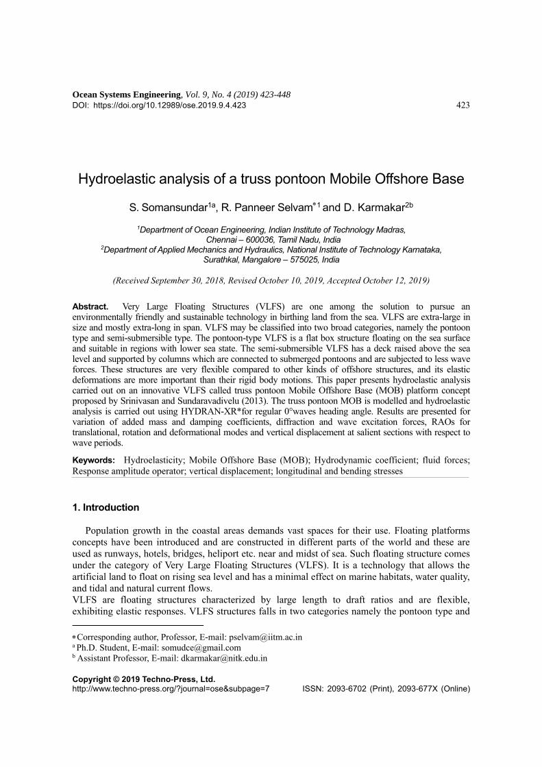
Table 3 Description of the element details of truss pontoon MOB platform of a single module
Description No. of
Nodes
No. of
elements
No. of
items
Total
Nodes
Total
elements
Keel tank (bottom hull) 502 490 14 7028 6860
Column 286 261 14 4004 3654
Longitudinal tubular pontoon 44 40 12 528 480
Transverse tubular pontoon 84 78 7 588 546
Longitudinal beam 2030 1890 2 4060 3780
Transverse beam 294 264 7 2058 1848
4. Results and discussion
The numerical analysis is carried out on the truss pontoon MOB using HYDRAN-XR which
yields the rigid body modes and deformational modes. The analysis is performed for different dry
natural modes, elastic and hydrostatic stiffness, forces and responses of the deformable and rigid
bodies.
4.1 Natural period and modes
Natural periods in dry and wet conditions are obtained using HYDRAN-XR. The dry natural
modes are categorized as rigid and flexible or deformational modes. The modes 1-6 correspond to
dry rigid body modes and represent the six degrees of freedom namely the surge, sway, heave, roll,
pitch and yaw and these dry natural frequencies are zero. The modes 7-18 corresponds to
additional generalized modes due to the flexibility of the body and the details of these flexible or
deformational modes and their corresponding natural frequencies are presented in Table 4. The dry
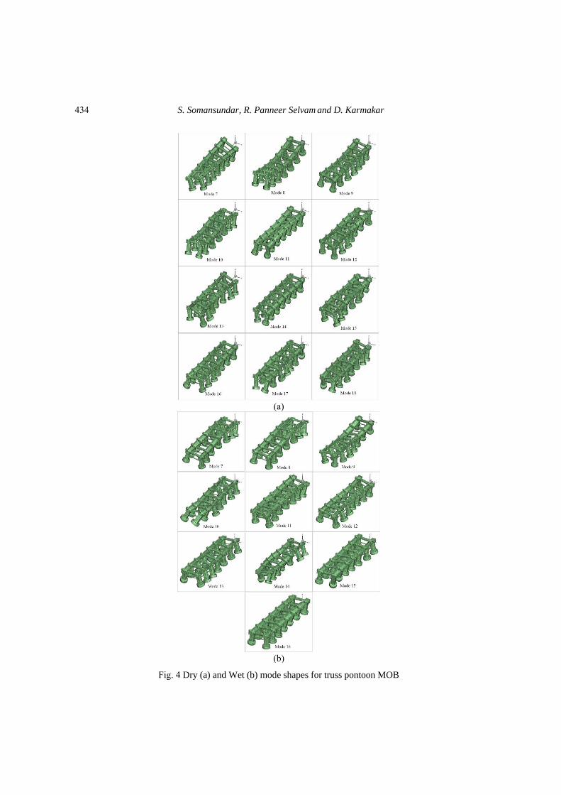
and wet mode shapes are shown in Figs. 4(a) and 4(b) and it is observed that the mode shapes are
similar to freely floating structure. For dry modes, the deformational modes 7 is purely torsional,
and modes 8, 10 are purely vertical bending modes and other modes are mostly torsional or
combination of vertical, horizontal and torsional modes. For wet modes, the deformational mode 8
is purely bending and other modes are combination of bending and torsional modes. The wave
induced motions of the truss pontoon MOB are obtained from a subset of the dry normal modes to
form a reduced basis. The wet natural periods and modes falling in the wave excitation ranges 2-25
s (seconds) were obtained with error less than 1% and are given in Table 5. Comparison of dry
natural periods and modes for truss pontoon MOB for some deformational modes (error less than
1%) is given in Table 6. The error here is computed as ω−ωn
ω×100, where n is the wet natural
frequency and is the wave frequency. Comparing the natural periods of wet mode and dry mode
it can be seen that three modes namely 7, 8 and 9 have wet natural periods higher than dry natural
periods. For these cases it can be observed that the added masses are mostly positive. For modes
13, 14, 15, 16 the dry natural periods are higher than wet natural periods. For these cases it can be
observed that the added masses are negative. The combination of increased magnitude of stiffness
and positive and negative added masses determines which of the natural periods (dry/wet) is
higher.
432
Hydroelastic analysis of a truss pontoon Mobile Offshore Base
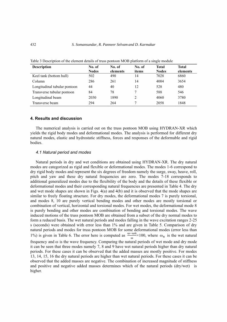
Table 4 Dry natural periods and modes for truss pontoon MOB
Dry Mode No. Natural period (s) Description
7 12.00 Torsion 1
8 11.83 Vertical bending 1
9 6.29 Combination of bending & torsion 1
10 5.31 Vertical bending 2
11 5.09 Combination of bending & torsion 2
12 4.97 Combination of bending & torsion 3
13 4.56 Combination of bending & torsion 4
14 4.24 Combination of bending & torsion 5
15 4.03 Combination of bending & torsion 6
16 4.00 Combination of bending & torsion 7
17 3.88 Combination of bending & torsion 8
18 3.69 Combination of bending & torsion 9
Table 5 Wet natural periods and modes
Modes Wet natural
periods (s)
Error <1% Description of wet mode (bending & torsion)
7 26.43 0.265 Combination 1
8 18.43 0.409 Vertical bending 1
9 12.94 0.468 Combination 3
10 6.3 0.136 Combination 4
11 5.28 0.446 Combination 5
12 4.99 0.132 Combination 6
13 4.38 0.666 Combination 7
14 3.89 0.335 Combination 8
15 2.39 0.425 Combination 9
16 2.19 0.668 Combination 10
433
S. Somansundar, R. Panneer Selvam and D. Karmakar
(a)
(b)
Fig. 4 Dry (a) and Wet (b) mode shapes for truss pontoon MOB
434

Hydroelastic analysis of a truss pontoon Mobile Offshore Base
4.2 Elastic and hydrostatic stiffness
In the case of a freely floating structure the restoring forces exists only in modes 3-5 namely
heave, roll and pitch. So for modes 3-5, the only contribution for the freely floating structure is the
hydrostatic stiffness. For the analysis of the large floating structure the elastic stiffness are also
considered along with the hydrostatic stiffness for the deformational modes. Hydrostatic stiffness
includes both stiffness effect of the fluid and structural geometric stiffness. Elastic stiffness here
refers to material structural stiffness (the bending stiffness EI). In Table 7 the elastic stiffness and
hydrostatic stiffness for the modes 7-18 along with the percentage of elastic is presented for
deformational modes. Since the modes have been mass normalized the elastic stiffness represents
square of the natural frequencies as discussed in Riggs et al. (2007). It is observed that the
contribution of elastic stiffness is less than 6.5 % for modes 7-18, except for mode 13, where it is
about 11% and this is not the case for a barge wherein elastic stiffness contributions are of the
same order for lower deformational modes and less than one percent for higher modes (Riggs et al.
2007).
4.2.1 Added mass coefficient The added mass for rigid modes is shown in Figs. 5(a) and 5(b) which corresponds to the linear
and rotational modes of a rigid body. For the deformational modes the added mass moment of
inertia for modes 7-18 are shown in Figs. 5(c)-5(f). It can be observed that for the rigid body
modes the added mass values are positive and mass moment of inertia values are in the order of
1012. For mode 7 the values are about 1/1000th of rigid modes (roll, pitch and yaw) and the modes
above 10 exhibit negative values with the highest negative mass moment of inertia is observed for
mode 18. In the deformational modes for most of them the negative value indicates less fluid
resistance in these modes and hence for a given excitation the motion contribution by these modes
is relatively significant.
Table 6 Comparison of dry and wet natural periods
Modes Dry natural period
(s)
Wet natural
periods (s)
7 12.00 26.43
8 11.83 18.43
9 6.29 12.94
10 5.31 6.3
11 5.09 5.28
12 4.97 4.99
13 4.56 4.38
14 4.24 3.89
15 4.03 2.39
16 4.00 2.19
435

S. Somansundar, R. Panneer Selvam and D. Karmakar
Fig. 5 Added mass coefficient for truss pontoon MOB
Table 7 Generalized Diagonal Stiffness Coefficients for truss pontoon MOB
Dry Mode no. Elastic Hydrostatic % Elastic
7 0.274 15.30 1.790
8 0.282 9.380 3.006
9 0.997 54.30 1.836
10 1.40 22.80 6.140
11 1.530 43.50 3.517
12 1.60 33.70 4.747
13 1.90 17.51 10.850
14 2.20 82.40 2.669
15 2.44 80.30 3.038
16 2.46 96.30 2.554
17 2.62 56.0 4.678
18 2.88 45.0 6.40
436

Hydroelastic analysis of a truss pontoon Mobile Offshore Base
4.2.2 Damping coefficient The damping coefficient values for rigid modes is shown in Figs. 6(a) and 6(b) which
corresponds to the linear and rotational modes of a rigid body and are all positive values exhibiting
loss of energy in motion. For the deformational modes the damping moment are positive as well as
negative and for some modes the values are mostly negative for different wave periods. The
negative damping values indicate that for these modes and periods there is no fluid resistance for
the body, thereby increasing the response of the body. Strong frequency dependency is observed
for modes 7-18 as shown in Figs. 6(c)-6(e).
Fig. 6 Damping coefficient for truss pontoon MOB
437

S. Somansundar, R. Panneer Selvam and D. Karmakar
Fig. 7 Diffraction forces for 0 wave heading angle of truss pontoon MOB
4.2.3 Diffraction force The presence of large body in waves diffracts waves and one component of wave excitation
force is due to the diffraction force. In Figs. 7(a) and 7(b), the diffraction force for the rigid body
modes is presented and it is observed that, the diffraction force increases with wave period and the
diffraction force in the surge and heave direction are higher than that of sway direction for 0° wave
heading angle. The diffraction moment shows an increasing trend as the wave periods increase.
The pitch exciting moment is higher of the order four as compared to surge and yaw exciting
moment. The diffraction moment for deformational modes are shown in Figs. 7(c) and 7(d) and it
can be observed that for the mode7 and mode 9, the diffraction force are close to zero for wave
period below 15 s. Significant variation in the moment are observed for mode 8, 10 and 18. This
suggests that, the nature of bending and twisting has a pronounced effect on the diffraction forces.
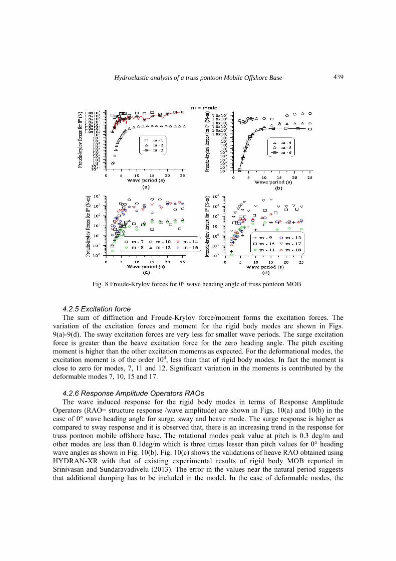
4.2.4 Froude Krylov force The Froude-Krylov force is due to incident waves and these forces and moment for the rigid
body modes are shown in Figs. 8(a)-8(d) It is easy to observe that the sway forces are small and
close to zero, especially for wave periods below 8 seconds. The surge force is greater than the
sway force for wave periods below 17 s and these forces are of same order for higher wave periods.
The pitch exciting moment dominates over the roll and yaw exciting moments as seen from Fig.
8(b) and for the deformational modes, these moments are small and close to zero for modes 7, 9,
11 and 12. Significant variations in the moment are contributed by modes 8, 10, 15 and 17 as
shown in 8(c)-8(d).
438
Hydroelastic analysis of a truss pontoon Mobile Offshore Base
Fig. 8 Froude-Krylov forces for 0 wave heading angle of truss pontoon MOB
4.2.5 Excitation force The sum of diffraction and Froude-Krylov force/moment forms the excitation forces. The
variation of the excitation forces and moment for the rigid body modes are shown in Figs.
9(a)-9(d). The sway excitation forces are very less for smaller wave periods. The surge excitation
force is greater than the heave excitation force for the zero heading angle. The pitch exciting
moment is higher than the other excitation moments as expected. For the deformational modes, the
excitation moment is of the order 104, less than that of rigid body modes. In fact the moment is
close to zero for modes, 7, 11 and 12. Significant variation in the moments is contributed by the
deformable modes 7, 10, 15 and 17.
4.2.6 Response Amplitude Operators RAOs The wave induced response for the rigid body modes in terms of Response Amplitude
Operators (RAO= structure response /wave amplitude) are shown in Figs. 10(a) and 10(b) in the
case of 0° wave heading angle for surge, sway and heave mode. The surge response is higher as
compared to sway response and it is observed that, there is an increasing trend in the response for
truss pontoon mobile offshore base. The rotational modes peak value at pitch is 0.3 deg/m and
other modes are less than 0.1deg/m which is three times lesser than pitch values for 0° heading
wave angles as shown in Fig. 10(b). Fig. 10(c) shows the validations of heave RAO obtained using
HYDRAN-XR with that of existing experimental results of rigid body MOB reported in
Srinivasan and Sundaravadivelu (2013). The error in the values near the natural period suggests
that additional damping has to be included in the model. In the case of deformable modes, the
439

S. Somansundar, R. Panneer Selvam and D. Karmakar
Fig. 9 Wave excitation forces for 0 wave heading angle of truss pontoon MOB
Fig. 10 RAOs of translation, rotation of truss pontoon MOB for 0 wave heading angle
bending moment RAOs are shown in Figs. 11(a) and 11(b) for 0° wave heading angle. The
bending moment for most of the modes peaks near wave period of 15 s and for mode-12 and
mode-13 peak values are 4.0x10³N-m/m and 1.2x10³ N-m/m respectively. The coupled
amplification of mode 12 and 13 with pitch at secondary peak of 15 s is attributed to the
significant off diagonal modal mass values i.e., m (5, 12), m (5, 13). These deformable bending
moments are combination of bending and torsion as well as wave characterises.
0 5 10 15 20 25
Wave period (s)
0
0.4
0.8
1.2
1.6
RA
O f
or
0°
(m
/m)
Surge
Sway
Heave
0 5 10 15 20 25
Wave period (s)
0
0.1
0.2
0.3
RA
O f
or
0°
(deg
/m)
Roll
Pitch
Yaw
(a) (b)
0 10 20 30
Wave period (s)
0
1
2
3
4
5
Hea
ve
RA
O f
or
0°
(m
/m)
Experiment (Srinivasan et al.2013)
Numerical (HYDRAN-XR.)
(c)
440

Hydroelastic analysis of a truss pontoon Mobile Offshore Base
Fig. 11 RAOs of Bending moment for deformational modes of truss pontoon MOB for 0 wave heading
angle
Fig. 12 View the nodal points of truss pontoon MOB
4.2.7 Vertical displacement The vertical displacements are obtained for the nodal points shown in Fig. 12, which are centre
of keel tanks. The vertical displacements for these nodal points by considering the body as
‘hydroelastic’ and ‘rigid’ are compared in Figs. 13(a)-13(n) for 0° wave heading angle for fourteen
different nodal points. From these graphs it can be seen that the rigid body responses are lower
compared to elastic body in most of the wave periods in the range of 5-20 s. Hence it is concluded
that the vertical displacement of the rigid body assumption underestimates the vertical
displacements. On the other hand for higher wave periods the vertical displacement for both rigid
and elastic body increases. Table 8 compares the values of peak vertical displacements along
sections AA and BB at the nodal points for elastic body and rigid body.
0 5 10 15 20 25
Wave period (s)
0.0
103
2.0x10³
3.0x10³
4.0x10³
RA
O o
f B
endin
g m
om
ents
for
0°
(N-m
/m) m - 7
m - 8
m - 9
m - 10
m - 11
m - 12
0 5 10 15 20 25
Wave period (s)
0.0
4.0x10²
8.0x10²
1.2x10³
RA
O o
f B
endin
g m
om
ents
for
0°
(N-m
/m)
m - 13
m - 14
m - 15
m - 16
m - 17
m - 18
m = mode
(a) (b)
441

S. Somansundar, R. Panneer Selvam and D. Karmakar
Fig. 13 Comparison of vertical displacement of rigid and elastic body
Fig. 14 Peak value of vertical displacement of the truss pontoon MOB
-225 -150 -75 0 75 150 225
Longitudinal section B-B(length of the body)
0.8
1.2
1.6
2
2.4
Ver
tica
l. d
isp @
25.5
s (
m/m
)
0° section A-A 0° Section B-B
-225 -150 -75 0 75 150 225
Longitudinal section A-A(length of the body)
0
0.4
0.8
1.2
1.6
2
Ver
tica
l. d
isp @
15 s
(m
/m)
(a) (b)
442

Hydroelastic analysis of a truss pontoon Mobile Offshore Base
Table 8 Peak Displacement Comparison of rigid body and elastic body of truss pontoon MOB
Description Rigid body (m/m) Elastic body (m/m)
Section BB Section AA Section BB Section AA
At Centre of bottom
keel tank
1.5 1.5 1.42 1.1
From origin of the
right corner x-axis
1.5 1.55 2.2 1.82
From origin of the
left corner x-axis
1.65 1.6 1.61 1.53
From x-axis
coordinates at (150,
46.6, -61.42)
1.5 1.6 2 1.71
From x-axis
coordinates at (-150,
46.6, -61.42)
1.9 1.9 1.17 1.1
From x-axis
coordinates at (75,
46.6, -61.42)
1.5 1.5 1.78 1.51
From x-axis
coordinates at (-75,
46.6, -61.42)
1.6 1.6 1.12 0.98
The vertical displacement profile of the truss pontoon MOB for two wave periods, 15 s and
25.5 s, wherein the vertical displacements are maximum, are shown in Figs. 14(a) and 14(b).
These are plotted along the longitudinal direction on either side of the truss pontoon MOB and
combinational effects on bending and torsion along the longitudinal section is discussed. Fig. 14(a)
shows the displacement of the truss pontoon MOB are asymmetric at the wave period 15 s and the
model slightly tilt from the section A-A to section B-B at wave period 25.5 s. Considering a wave
of 30 m this corresponds to a maximum displacement of about 60 m at one end of the truss
pontoon in severe seas in isolated model. However these displacements vary in multi-module case
and if necessary dampers have to be installed to reduce vertical displacements.
The rotation about x-axis of is shown in Figs. 15(a)-15(g) for 0° wave heading angle for different
nodal points along the centreline, in longitudinal direction at the top deck level. The rotation about
x-axis is of almost same order for different nodal point but it is observed less for lower wave
periods. The rotation about y-axis is shown in Figs. 16(a)-16(g) for 0° wave heading angle. The
rotation about y-axis increases with wave period. The nodal point rotation about y-axis is same
order as that of the x-axis rotation. The rotations are less than one degree for unit wave height. The
maximum longitudinal stresses in entire region except top deck of truss pontoon MOB is shown in
Fig. 17 for 0° wave heading angle. It is observed that the longitudinal stress variation is above
1.0x10⁴ Mpa/m for most of the regions and very less near the far end (rear) of the MOB. Further,
the maximum longitudinal stresses in top deck of truss pontoon MOB is shown in Fig.18 for 0°
wave heading angle. The variation in the maximum longitudinal stress in the top deck is observed
in the middle portion of the top deck. A comparison of the performance of the truss pontoon MOB
with that of a barge whose length is 100 m and width and draft are one order smaller, analysed by
Riggs et al. (2007) is shown in Table 9.
443

S. Somansundar, R. Panneer Selvam and D. Karmakar
0 5 10 15 20 25
Wave period (s)
0
0.002
0.004
0.006
0.008
0.01
X-r
otat
ion
(0,0
,21.
58)
(deg
/m)
0 5 10 15 20 25
Wave period (s)
0
0.004
0.008
0.01
X-r
otat
ion
(75,
0,21
.58)
(de
g/m
)
0°
0 5 10 15 20 25
Wave period (s)
0
0.005
0.01
0.01
0.02
0.03
X-r
otat
ion
(-75
,0,2
1.58
) (d
eg/m
)
0 5 10 15 20 25
Wave period (s)
0
0.005
0.01
0.01
0.02
0.03
X-r
otat
ion
(150
,0,2
1.58
) (d
eg/m
)
0 5 10 15 20 25
Wave period (s)
0
0.004
0.008
0.01
0.02
0.02
X-r
otat
ion
(-15
0,0,
21.5
8) (
deg/
m)
0 5 10 15 20 25
Wave period (s)
0
0.01
0.02
0.03
X-r
otat
ion
(225
,0,2
1.58
) (d
eg/m
)
0 5 10 15 20 25
Wave period (s)
0
0.004
0.008
0.01
X-r
otat
ion
(-22
5,0,
21.5
8) (
deg/
m)
(a) (b) (c)
(d)(e) (f)
(g)
Fig. 15 X-rotation of truss pontoon MOB
Table 9 Comparison of barge (100×10×2 m draft 1 m) and truss pontoon MOB (500×135×83 draft 61.42 m)
Si
no.
Description Barge (Riggs et al.2007) Truss pontoon MOB
1 Heave RAO maximum 1.1 (m/m) (at peak) 1.4 (m/m)
(up to 25.5 sec)
2 Generalized Diagonal elastic stiffness
coefficient
7.78 & 978 (max. & min.) 0.274 & 2.88
(max. & min.)
3 Vertical displacement at mid-ships for
flexible
1.0 (m/m) 0.9 (m/m)
4 Vertical displacement at edge 1.3 (m/m) 2.2 (m/m)
5 Longitudinal stress 18 (Mpa/m)
(at Center of top deck
10 (Mpa/m)
444

Hydroelastic analysis of a truss pontoon Mobile Offshore Base
0 5 10 15 20 25
Wave period (s)
0
0.01
0.02
0.03
Y-r
otat
ion
(0,0
,21.
58)
(deg
/m)
0 5 10 15 20 25
Wave period (s)
0
0.004
0.008
0.01
0.02
0.02
Y-r
otat
ion
(75,
0,21
.58)
(de
g/m
)
0°
0 5 10 15 20 25
Wave period (s)
0
0.004
0.008
0.01
0.02
Y-r
otat
ion
(-75
,0,2
1.58
) (d
eg/m
)
0 5 10 15 20 25
Wave period (s)
0
0.004
0.008
0.01
Y-r
otat
ion
(150
,0,2
1.58
) (d
eg/m
)
0 5 10 15 20 25
Wave period (s)
0
0.004
0.008
0.01
0.02
0.02
Y-r
otat
ion
(-15
0,0,
21.5
8) (
deg/
m)
0 5 10 15 20 25
Wave period (s)
0
0.004
0.008
0.01
0.02
Y-r
otat
ion
(225
,0,2
1.58
) (d
eg/m
)
0 5 10 15 20 25
Wave period (s)
0
0.01
0.02
0.03
0.04
Y-r
otat
ion
(-22
5,0,
21.5
8) (
deg/
m)
(a) (b) (c)
(d) (e) (f)
(g)
Fig. 16 Y-rotation of truss pontoon MOB
Fig. 17 Maximum longitudinal stresses in entire region except top deck of truss pontoon MOB for 0
wave angle (values in MPa/m)
445

S. Somansundar, R. Panneer Selvam and D. Karmakar
Fig. 18 Maximum longitudinal stresses in top deck of truss pontoon MOB for 0 wave angle (values in
MPa/m)
5. Conclusions
This paper presents hydroelastic analysis carried out on an innovative VLFS called truss
pontoon Mobile Offshore Base (MOB) platform concept proposed by Srinivasan and
Sundaravadivelu (2013). The MOB is modelled and hydroelastic analysis is carried out using
HYDRAN-XR* for regular 0° waves heading angle. Results are presented for variation of added
mass and damping coefficients, diffraction and wave excitation forces, RAOs for translational,
rotational and deformational modes and vertical displacement at salient sections, rotations along
longitudinal and transverse directions for wave periods ranging from 2- 25 s. Peak stresses and
bending moment for the entire structures are also obtained. Comparison of rigid body and elastic
body of nodal vertical displacement brings out the importance of hydroelastic analysis of the
structure wherein the displacements predicted are higher. This study helps in performance
evaluation of the truss pontoon VLFS in different sea conditions and further adopt design
modifications for safe utility. Further analysis has to be carried out for multi body case and
validate the numerical studies using experimental measurements on a scaled elastic truss pontoon
MOB.
446

Hydroelastic analysis of a truss pontoon Mobile Offshore Base
Acknowledgements
The authors would like to acknowledge IIT Madras for supporting financially to perform the
research work and also thank Prof. H. Ronald Riggs, University of Hawaii at Manoa, for providing
valuable insights in HYDRAN-XR*.
References
Barrientos, M.A., Gatica, G.N., Rodríguez, R. and Torrejón, M.E. (2004), “Analysis of a coupled
BEM/FEM Eigen solver for the hydroelastic vibrations problem”, ESAIM: Math. Model. Numer.
Anal., 38(4), 653-672.
Bishop, R.E.D. and Price, W.G. (1976), “On the relationship Between Dry modes and Wet modes in the
theory of ship Response”, J. Sound Vib., 45(2), 157-164.
Bishop, R.E.D., Price, W.G. and Wu, Y. (1986), “A general linear hydroelasticity theory of floating
structures moving in a seaway”, Royal Society, 316(1538), 375-426
Chakrabarti, S.K. (1987), Hydrodynamics of Offshore Structures, WIT press.
Huang, L.L. and Riggs, H.R. (2005), “Development of a new interfacing strategy for fluid-structure
interaction”, J. Eng. Maritime Environ., 219, 131-148.
ISSC.(2006), “Report of specialist Task Committee VI.2, very large floating structures”, (Eds., Frieze, P.A.,
Shenoi, R.A.), Proceedings of the 16th International Ship and Offshore Structure Congress, Southampton,
UK.
Kim, B.W., Hong, S.Y., Kyoung, J.H. and Cho, S.K. (2007), “Evaluation of bending moments and shear
forces at unit connections of very large floating structures using hydroelastic and rigid body
analyses”, Ocean Eng., 34(11-12), 1668-1679.
Lee, S.W. and Webster, W.C. (1994), “A preliminary to the design of a hydroelastic model of a floating
airport”, Proceeding of the International Conference on Hydroelasticity in Marine Technology,
Trondheim, Norway.
Liu, J., Riggs, H.R. and Tessler, A. (2000), “A four-node shear deformable shell element developed via
explicit Kirchhoff constraints”, Int. J. Numer. Meth. Eng., 49, 1065-1086.
Patran, M.S.C. (2016), User’s Guides and Reference Manuals.
Pinkster, J.A. and Scholte, E.M. (2001), “The behaviour of a large air-supported MOB at sea”, Mar. Struct.,
14(1-2), 163-179.
Riggs, H.R. (2016), Hydrodynamic Response Analysis with Integrated Structural Finite Element Analysis,
HYDRAN-XR, v 16.3.
Riggs, H.R. and Ertekin, R.C. (1998), “Impact of connector stiffness on the response of a multi-module
mobile offshore base”, Proceedings of the 8th International Offshore and Polar Engineering Conference,
Montreal, Canada.
Riggs, H.R. and Ertekin, R.C. (1999), “Response characteristics of serially connected semisubmersibles”, J.
Ship Res., 43(4), 229-240.
Riggs, H.R., Hideyuki, S., Ertekin, R.C., Jang, W.K. and Iijima, K. (2008), “Comparison of hydroelastic
computer codes based on the ISSC VLFS benchmark”, Ocean Eng., 35, 589-597.
Riggs, H.R., Niimi, K.M. and Huang, L.L. (2007), “Two benchmark problems for three-dimensional, linear
hydroelasticity”, J. Offshore Mech. Arct., 129, 149-157.
Srinivasan, N. and Sundaravadivelu, R. (2013), “Ocean space utilization using very large floating
semi-submersible”, Proceedings of the ASME 32nd international Conference on Ocean, Offshore and
Arctic Engineering, Nantes, France.
Srinivasan, N., Chakrabarti, S. and Radha, R. (2006), “Response analysis of a Truss-Pontoon
Semisubmersible with Heave-Plates”, J. Offshore Mech. Arct., 128.
447

S. Somansundar, R. Panneer Selvam and D. Karmakar
Suzuki, H., Yoshida, K. and Iijima, K. (1996), “A consideration of the structural design of a large-scale
floating structures”, J. Mar. Sci. Technol., 1, 255-267.
Tulin, M.P. (1999), “Hydroelastic scaling”, Proceedings of 3th International Workshop on Very Large
Floating Structures, Honolulu, Hawaii, USA.
Venkataraman, V. (2001), “Dynamic response of a mobile offshore base hydroelastic test model”, M.S.
dissertation, The university of Maine.
Wang, C.M. (2015), “Mega floating structures”, Singapore maritime technology conference, Singapore.
Wu, Y., Wang, D., Riggs, H.R. and Ertekin, R.C. (1993), “Composite singularity distribution method with
application to hydroelasticity”, Mar. Struct., 6, 143-163.
Zueck, R., Palo, P. and Taylor, T. (1998), “Mobile offshore base”, Proceedings of the 8th International
Offshore and Polar Engineering Conference, Montreal, Canada.
MK
448