Embed Size (px)
Citation preview
AQTR 2004 (THETA 14)2004 IEEE-TTTC - International Conference on Automation, Quality and Testing, Robotics
May 13 – 15, 2004, Cluj-Napoca, Romania
1 of 6
HYDRO-ELECTRIC POWER PLANTS SCADA SYSTEM –APPLIED ON THE SOMES RIVER
Ioan Stoian*, Dorina Căpăţînă*, Ovidiu Ghiran*, Eugen Stancel*
* SC IPA SA Cluj-Napoca Subsidiary109 Republicii Str., 400489 Cluj-Napoca, Romania
Tel: +40264 596155, fax: +40264 [email protected], [email protected], [email protected],[email protected]
Abstract: The hydroelectric power plants are in a process of rehabilitation and upgrade toensure optimized operation. One method of optimization of the power production plants is toprovide the remote control of all power production units using a SCADA system. The telematicsystem has a PC-based, two-level distributed architecture:- the local level is in the control structure, located on the plant platform, the connection andcommunication interface, located in the hydroelectric power plant control room,- the central level located at the territorial dispatcher.This type of system handles both software and hardware techniques based on PC resources,PLCs, RTUs, smart sensors, actuators, data communication and transfer devices.
Keywords: telematic system, distributed automation architecture, power energy management
1. INTRODUCTIONSCADA (supervisory control and data acquisition) is an industrial measurement
and control system consisting of a central host or master (usually called a master station,master terminal unit or MTU); one or more field data acquisition and control units orremotes (usually called remote stations, remote terminal units, or RTU's); a collection ofstandard and/or custom software used to monitor and control remotely located field dataelements. Contemporary SCADA systems exhibit predominantly open-loop controlcharacteristics and utilize predominantly long distance communications, although someelements of closed-loop control and/or short distance communications may also bepresent.
Systems similar to SCADA systems are regularly seen in factories,manufacturing plants etc. These are often referred to as Distributed Control Systems(DCS). They have similar functions to SCADA systems, but the field data acquisition orcontrol units are usually located within a more confined area. Data communicationsmay be achieved via a local area network (LAN), and will normally be reliable and highspeed. A DCS system usually operates significant amounts of closed loop control.
In this paper it is succinctly presented the SCADA architecture built andimplemented on the hydroelectric power plants from the Somes River and the way itmeats the SCADA system requirements.
AQTR 2004 (THETA 14)2004 IEEE-TTTC - International Conference on Automation, Quality and Testing, Robotics
May 13 – 15, 2004, Cluj-Napoca, Romania
2 of 6
2. MAIN FEATURES OF THE SCADA SYSTEM OF THESOMES HYDROELECTRIC POWER PLANTS
The remote measuring, data acquisition and supervising system achieves themodernisation of the dispatching activities for seven hydroelectric power plants. Thenewly added telematic system provides to the existing equipment with a remotemeasurement and control unit, integrated computing systems and digital processingdevices.
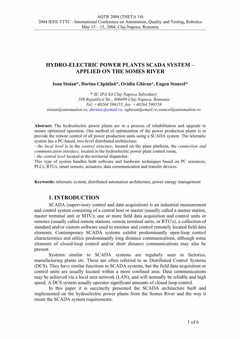
The telematic system, as seen in figure 1, is structured on two levels: Local control & connection level –the hydroelectric power plant unit includes
transducers, actuators, RTUs (power meters and level measurement blocks) and aPLC used in parameters measurement, supervising and control of the process. Thelocal control level equipment processes the electrical measurements (analog anddigital signals) acquired from the electric equipment of the hydroelectric powerplants. The digital input signals represent the function status of switching equipmentand the real-time protection loops status. The analog signals include electricparameters, such as: voltage, currents, power factor, frequency and energyparameters: active, reactive and apparent power and energies. Data communicationstructure is implemented by a computing system, attached to the local controlstructure using a serial data communication network RS485 (Modbus and Standard);this level provides the HMI (human machine interface), data logging, eventsrecording, process parameters plotting. The telematic system located at thedispatcher is connected to the hydroelectric power plant equipment using leased/dial-up telephone lines or GSM/radio communication.
Figure 1 – Telematic system architecture
AQTR 2004 (THETA 14)2004 IEEE-TTTC - International Conference on Automation, Quality and Testing, Robotics
May 13 – 15, 2004, Cluj-Napoca, Romania
3 of 6
Central level - a SCADA type architecture system implemented at the electricpower plant headquarter (dispatcher). This consists of an Ethernet computingsystems network using TPC/IP protocol under the Windows operating system. Eachcomputer from the network is dedicated to a special department (see figure 1). Thereis a Main Dispatcher computer, that is the communication processor, connected tothe local level by multiple-port interfaces, which manage the seven communicationchannels. The Dual Dispatcher computer is the acquisition data base host.Concerning the remote operating process the two dispatcher station are equivalent.The other network computers ensure the visibility of the measured parameters, ownfor each department, but cannot generate commands and remote control for thehydroelectric plants.
3. FUNCTIONS OF THE SCADA SYSTEM OF THE SOMESHYDROELECTRIC POWER PLANTS
The SCADA system of the hydroelectric power plants provides the followingfunctions:• data communication• data acquisition
- digital signal representing power switches status, equipment functional status,relay-based protection loops status, substation distribution units, binary andcontrol loop functions, utilities status
- analogue parameters representing electric parameters, powers, energies, flows,pressures, water-levels
• digital and analog measured value processing for operative alarming- checking its pre-programmed limits- checking its transmission correctness
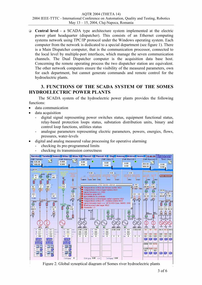
Figure 2. Global synoptical diagram of Somes river hydroelectric plants
AQTR 2004 (THETA 14)2004 IEEE-TTTC - International Conference on Automation, Quality and Testing, Robotics
May 13 – 15, 2004, Cluj-Napoca, Romania
4 of 6
• remote operating functions- remote operating command management- commands execution visibility assurance- main type commands: power switch connect/disconnect, programming setpoints
for active and reactive power, hydroelectric generators power on/off• remote plants visibility - real-time hydroelectric power plants and substations
dispatching- current status of the main remote operated elements and alarms are represented
on the global synoptical panel on a wide display connected to Dual DispatcherComputer (see figure 2)
- operating user interfaces for each substation based on dynamic electric diagram• digital and analog parameters recording at process status relevant time intervals
(historical data acquisition and report files)- historical files displaying in graphical or spread-sheet format, selected by the
operator- actuators operating time used in service and maintenance management
• security job is assured by the private Intranet network and by a multilevel accesspassword system of the critical operations
4. SOMES HYDROELECTRIC POWER PLANTS SCADASYSTEM REQUIREMENTS
The control of the power plants includes many tasks distributed to hydraulicengines, electric generators, specific power and voltage controller units, connectingdevices, control loops and utilities. The SCADA system for the Somes valleyhydropower stations and the dispatching unit is designed, manufactured andimplemented by IPA Cluj Subsidiary specialists. It covers a large geographic area that iswhy it must meets a lot of important requirements:♦ Openness. The telematic system is open and includes different computer based
hardware equipment, managed by software application developed underprogramming environment from different suppliers. It can operate with othersystems from different departments such as: production management, service andmaintenance, national energetic dispatching system, water resources management.
♦ Adaptability. That means that the system is able to configure its componentsaccording precise requirements, even if these are modified during the lifetime of thesystem. The Somes SCADA system offers the possibility of configuration for:- automation equipment components such as: digital input/output, analog input,
communication transfer parameters, data acquisition parameters, dynamicscreen controls
- hydropower plant parameters such as: power, voltage and current limit values,control loops parameters.
♦ Real time system. The SCADA system provides the measured data values and eventsample to the remote operator within a very short time to ensure its relevantprocessed actions in time. The Somes telematic system provides each second a newmeasurement from each supervised hydroelectric plant.
♦ Data security and reliability. A private Intranet network at central level of theSCADA Somes telematic system supports these requirements. Therefore the systemeliminates the access of the intruders the remote operation computer. For the safetyreasons between the radio modems (in free frequency domain) and leasing line

AQTR 2004 (THETA 14)2004 IEEE-TTTC - International Conference on Automation, Quality and Testing, Robotics
May 13 – 15, 2004, Cluj-Napoca, Romania
5 of 6
modem communication the second one was chosen. The data organization andmanagement is an other way to improve the system security. The first step ofprocessing is to store the measured values in a real time database, which may ensurean accurate observation of the system status and in the same time it is a non-volatilesupport for the permanent historical database. The historical database containsencrypted data. There is a custom own database type format but is possible to convertthe data into standard formats according to the system requirments.
♦ Friendly user interface. An important requirement for the user is for the interfacesto be as friendly as possible. The modern programming environments ensurevaluable tools but it is the programmers who design the screens. A task requested bythis design is to include data with equal significance so as to avoid a screenoverloading. Another task is to create friendly and reliable images. An example ofsuch a user interface in the SCADA system for hydropower plants on the Somesriver is shown in figure 3.
♦ Availability and correctness. The system has to rapidly detect the network faults.In a dedicated user interface the Somes SCADA system presents the availability ofthe plants, the status of the modem communication channels, industrial serialcommunication channels, PLCs, power meters, level measurement and otherexternal devices.
♦ Selftest module. A different component of the Somes SCADA system is the sefttestmodule that indicates or isolates a defective device or subdivision. In order to detectits corect functionality, a special test is done with each separate element. In case oferror the component is declared nonfunctional and the system works without it.
Figure 3 - Dispatcher user interface with synthetic data from Somes River plants
AQTR 2004 (THETA 14)2004 IEEE-TTTC - International Conference on Automation, Quality and Testing, Robotics
May 13 – 15, 2004, Cluj-Napoca, Romania
6 of 6
5. TECHNICAL SYSTEM CHARACTERISTICSThe Somes SCADA system assists the valley control operator to manage the
different plants according to the power schedule; it ensures the dams control andreservoir level regulation. The main features indicating the system dimensions are:
Digital logic inputs: 1040 (expandable in modules of 64) Digital logic outputs: 288 (expandable in modules of 16) Analogue PLCs inputs: 112 (expandable in modules of 16) Analogue ASCII inputs: 2100 (expandable in modules of 35) Number of control loops: 48 Number of local controlled smart units: 74 Number of communication channel: 30 Investigation rate: programmable between 1s and 1,5 s Variable duration of commands: programmable between 10ms and 2500ms Communication speed: 19200 bauds Number of user screen: 298 (between 30 and 44/ module) Medium controls: 200 per user display (dynamic 30/user screen)
6. CONCLUSIONFlexible architecture allows the easy upgrade of the system by the increasing of
number of new workstations and of new local controllers (PLCs or RTUs and third partsmart transducers). Continuous development of the power plant’s configuration andfunctions is possible without disturbing the initial system.
Sharing live data between applications or/and file servers across the enterprise,visualizing data are essential tools towards a better data user access and towards thepossibility of communicating the results to others. The network supervising system willhave the task of sharing monitored data with other groups in the company for datastoring, Web publishing, or offline analysis. The monitoring system uses industrystandards such as Ethernet with TCP/IP and OPC (OLE for Process Control) in order toshare data with the entire enterprise, from the dispatcher to the power station floor, dueto its low cost, high speed, and multiprotocol ability.
7. REFERENCES1. Bailey, David & Wright, Edwin, Practical Scada for Industry, Newnes2. Boyer, Stuart A. (1999), SCADA: Supervisory Control & Data Acquisition, Second
Edition, ISA3. Lopez, Orlando (2000), Qualification of SCADA Systems, Davis Horwood
International Publishers, Limited (DHI)4. Rogoz, Ioan & Chiorean, Dorin & Ordean, Mircea & Lehene, Cecilia & Stoian, Ioan
& Stancel, Eugen & Capatana, Dorina & Ghiran, Ovidiu & Manciu, Adriana (2003),Conducerea operativa a centralelor hidroelectrive din Amenajarea Somes de catreDispecerul Hidroenergetic Revista Energetica, vol 51 Nr. 8
5. Nise, Norman S. (2000), Control Systems Engineering, John Wiley & Sons; 3rd ed.6. Wiebe, Michael (2000), A Guide to Utility Automation: Amr, Scada, and It Systems
for Electric Power, Pennwell Pub7. Weigant, Jeff (1999), Creating HMI/SCADA Industrial Applications Using Microsoft
Access, Jeff Weigant8. ***, Handbook of Scada (Supervisory Control and Data Acquisition) Systems,
Elsevier Science


![Presentazione standard di PowerPoint€¦ · %Scad C] TOT portafC] Scad C] Scad 120 A Scad 120 C] Scad 150 A Scad 150 72468 261 618 45 go 188 527 C] Scad 180 A Scad 180 C] Scad 30](https://img.dokumen.tips/doc/110x75/60aafa6f3697c86f175cace5/presentazione-standard-di-scad-c-tot-portafc-scad-c-scad-120-a-scad-120-c-scad.jpg)