Embed Size (px)
Citation preview
Catalog 3123/USA
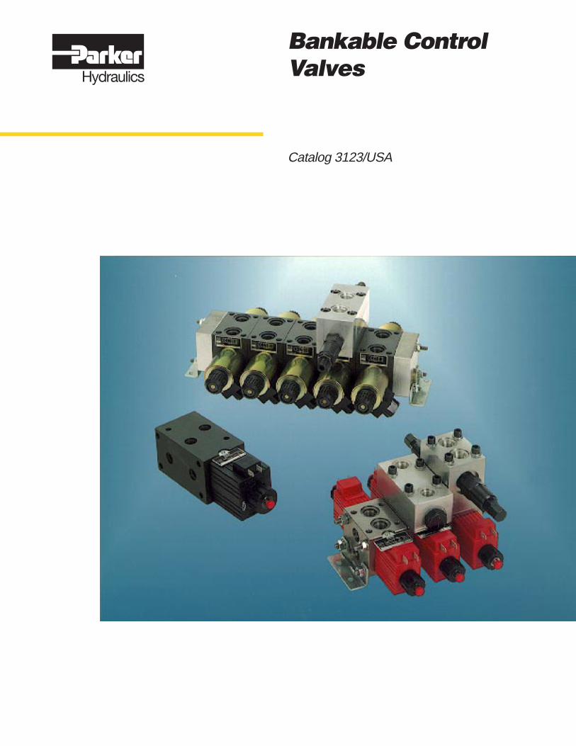
Bankable ControlValvesHydraulics

II
Parker Hannifin CorporationHydraulic Valve DivisionElyria, Ohio 44035 USAHydraulics
Catalog 3123/USA
bvcover.pm65, dd, jk
ContentsBankable Control Valves
FAILURE OR IMPROPER SELECTION OR IMPROPER USE OF THE PRODUCTS AND/OR SYSTEMS DESCRIBED HEREIN OR RELATED ITEMS CAN CAUSE DEATH, PERSONALINJURY AND PROPERTY DAMAGE.
This document and other information from Parker Hannifin Corporation, its subsidiaries and authorized distributors provide product and/or system options for further investigation by usershaving technical expertise. It is important that you analyze all aspects of your application and review the information concerning the product or system in the current product catalog. Dueto the variety of operating conditions and applications for these products or systems, the user, through its own analysis and testing, is solely responsible for making the final selection of theproducts and systems and assuring that all performance, safety and warning requirements of the application are met.
The products described herein, including without limitation, product features, specifications, designs, availability and pricing, are subject to change by Parker Hannifin Corporation and itssubsidiaries at any time without notice.
WARNING
The items described in this document are hereby offered for sale by Parker Hannifin Corporation, its subsidiaries or its authorized distributors. This offer and its acceptance are governedby the provisions stated in the "Offer of Sale".
Copyright 1998, Parker Hannifin Corporation, All Rights Reserved
Offer of Sale

Catalog 3123/USA
III
Parker Hannifin CorporationHydraulic Valve DivisionElyria, Ohio 44035 USAHydraulics
bvcover.pm65, dd, jk
ContentsBankable Control Valves
Series BV06 .........................................................................................................................................................1Technical Information .................................................................................................................................... 1Performance Curves ..................................................................................................................................... 2Dimensions ................................................................................................................................................... 3Ordering Information ................................................................................................................................. 4-5
Series BVB06 Inlets ............................................................................................................................................6Technical Information .................................................................................................................................... 6Dimensions ................................................................................................................................................ 7-8Ordering Information .................................................................................................................................... 9
Series BV06 Stack-On Valves ...........................................................................................................................10Technical Information ............................................................................................................................. 10-15Ordering Information ............................................................................................................................. 16-17
Series BV06 .......................................................................................................................................................18Assembled Valves ....................................................................................................................................... 18Assembly Configurations ............................................................................................................................ 19Stacking Kit and Configurations ................................................................................................ ................. 20Ordering Information .................................................................................................................................. 21
Series BV18 .......................................................................................................................................................22Technical Information .................................................................................................................................. 22Specifications ............................................................................................................................................. 23Construction Views ..................................................................................................................................... 24Performance Curves ................................................................................................................................... 25Technical Information .................................................................................................................................. 26Dimensions ............................................................................................................................................ 27-30Ordering Information ............................................................................................................................. 31-32
Series BV18 Inlets .............................................................................................................................................33Technical Information .................................................................................................................................. 33Dimensions ................................................................................................................................................ .34Ordering Information .................................................................................................................................. 35
Series BV18 Stack-Ons .....................................................................................................................................36Technical Information ............................................................................................................................. 37-41
Series BV18 End Plates ....................................................................................................................................42Technical Information .................................................................................................................................. 42Ordering Information ............................................................................................................................. 43-44Assembled Valves ........................................................................................................................................45Assembly Configurations .............................................................................................................................46Ordering Information ...................................................................................................................................47
Series BVCS10 ..................................................................................................................................................48Technical Information .................................................................................................................................. 48Performance Curves ................................................................................................................................... 49Dimensions ................................................................................................................................................. 50Ordering Information .................................................................................................................................. 51
Series BV ...........................................................................................................................................................52Installation Data .......................................................................................................................................... 52Cavity Details — No. 8 and 9 Size .............................................................................................. ................ 53Cavity Details — No. 10 and 12 Size ............................................................................................ .............. 54
Offer of Sale ........................................................................................................................................................55

THIS IS ABLANK PAGE

Hydraulics 1
Parker Hannifin CorporationHydraulic Valve DivisionElyria, Ohio 44035 USA
Bankable Control ValvesCatalog 3123/USA
bv06.p65, dd, jk
Series BV06
General Description
Series BV06 Bankables are 2 or 3 position, 4-way,solenoid operated directional control valves. Theyprovide a spool valve that can be used either individu-ally or in multiple spool banks. BV06 bankable valveshave auxiliary banking sections that can be mounted toprovide auxiliary functions such as an inlet relief orunloading function. In addition, stack-on sections canbe mounted on the cylinder port face of the BV06bankable valve spool sections to provide additionalfunctions such as crossover reliefs, cylinder portreliefs, P.O. checks, flow controls, and counterbal-ances. BV06 valves can be used to create custom,multi-functional circuits.
Features
• High flow capacity with reduced space requirements.
• High back pressure; all ports withstand maximumworking pressure.
• Precision machined valve body is made from hightensile cast iron.
• Six different spool styles are available.
• Available operators include single or double solenoids.
• All solenoids are a one-piece coil featuring numerousvoltages and terminations.
Technical Information
A
P
B
T
SpecificationsNominal Flow (at 70 PSI ∆∆∆∆∆P) 23-38 LPM (6-10 GPM) depending on spool
Maximum Inlet & Parallel: 210 Bar (3000 PSI) InletTank Pressure 210 Bar (3000 PSI) Tank
Series: 210 Bar (3000 PSI) Inlet & Tank
Porting SAE -6
Maximum Internal Leakage #1 Spool: 82 cc per land/min. (5.00 cu. in. per land/min.)@ 210 Bar (3000 PSI) #2 Spool: 164 cc per land/min. (10.01 cu. in. per land/min.)(110 SSU oil) #4 Spool: 82 cc per land/min. (5.00 cu. in. per land/min.)
#8 Spool: 82 cc per land/min. (5.00 cu. in. per land/min.)#11 Spool: 164 cc per land/min. (10.01 cu. in. per land/min.)
Operating Temperature Nitrile: -40°C to +93°C (-40°F to +200°F)Range (Ambient) Fluorocarbon: -32°C to +121°C (-25°F to +250°F)
Material Body: Precision machined and honed from cast iron.Spool: Hardened and ground steel.
Filtration ISO Code 16/13, SAE Class 4 or better
Mounting Position No restrictions
Mounting Type Individually or line mounted
Operation
The spool is shifted from its center position by energiz-ing one of the solenoids. Three-position spring centeredand two-position spring offset valves are available.

Hydraulics 2
Parker Hannifin CorporationHydraulic Valve DivisionElyria, Ohio 44035 USA
Bankable Control ValvesCatalog 3123/USA
bv06.p65, dd, jk
Series BV06
DC COILSPressure Response Full Shift
Spool Coil Type Pull In Drop Out Drop Out1 12 VDC, 30 Watt 30 ms 73 ms 244 ms2 12 VDC, 30 Watt 20 ms 10 ms 134 ms4 12 VDC, 30 Watt 23 ms 41 ms 287 ms8 12 VDC, 30 Watt 26 ms 13 ms 136 ms
11 12 VDC, 30 Watt 19 ms 22 ms 200 ms20 12 VDC, 30 Watt 17 ms 6.9 ms 244 ms21 12 VDC, 30 Watt 30 ms 73 ms 244 ms23 12 VDC, 30 Watt 30 ms 73 ms 244 ms24 12 VDC, 30 Watt 26 ms 13 ms 136 ms
Solenoid Code Nominal Voltage/Hz In Rush Amps Holding Amps WattageD012 12 VDC Not Applicable 2.3 30D024 24 VDC Not Applicable 1.2 30A120 120 VAC (Rectified Coil) Not Applicable 30
Performance Curves
Switching Limits
Differential Pressure
Note: Flow in center position for spool P11 as compared toP4 is 7% of the nominal flow.
Spool No./ P1, S2, S8,Flow Direction P21 P23 P4 P11 S24
Spool P to A or B 1 2 2 2 4
Shifted A or B to T 1 2 1 2 4
Spool P to T 2
Centered A or B to T 3
Solenoid Coil Specifications
Solenoid Response Times
Notes:
1. Unless otherwise specified, all curves were generatedusing solenoid actuators at 90% of rated with voltage.
2. All valves tested using 110 SSU oil.
069
10001041500
35500
1382000
1732500
2073000
Operating Pressure
0
1 3.8
2 7.6
4
3
15.1
11.4
5 18.9
6
7
8GPM
22.7
26.5
30.3LPM
Flow
(Q)
BarPSI
2, 81
4
1, 201, 4,11, 20
4, 11, 20
11
GPM
LPM0
13.8200
10.4150
6.9100
3.550
BarPSI17.3250
Pre
ssur
e D
rop
(P
)∆
100 2 6 84
Flow (Q)
37.90
1
4
32
7.6 22.7 30.315.1

Hydraulics 3
Parker Hannifin CorporationHydraulic Valve DivisionElyria, Ohio 44035 USA
Bankable Control ValvesCatalog 3123/USA
bv06.p65, dd, jk
Series BV06Dimensions
63.5(2.50)
Double Solenoid
45.0(1.77)
25.4 (1.00)1/4-20 UNC-2B x 11/16
(7.5) deep -4 places
#6 SAE6.4 (0.25)38.1
(1.50)
12.7(0.50)
Solenoid Tube20 N.m. (180 in.-lbs.)Torque
51.6(2.03)
47.6(1.88)
214.4(8.44)
6.4(0.25)
50.8(2.00)
24.6(0.97)
7.0(0.28)
31.8(1.25)
Single Solenoid
15.9(0.63)
10.7(0.42)
34.9(1.38)
138.6(5.46)
Extended Push TypeManual Overrides
Furnished
11.4(0.45)
*Inch equivalents for millimeter dimensions are shown in (**)

Hydraulics 4
Parker Hannifin CorporationHydraulic Valve DivisionElyria, Ohio 44035 USA
Bankable Control ValvesCatalog 3123/USA
bv06.p65, dd, jk
Series BV06Ordering Information
Code Description
06 22.7 LPM (6 GPM)Nominal Flow
Code Description
Omit Nitrile
V Fluorocarbon
Code Description Symbol
P1 30.0 LPM (8 GPM) Max. Flow*without Malfunction; Parallel Circuit Only
P4 22.7 LPM (6 GPM) Max. Flow*without Malfunction; Parallel Circuit Only
P11 26.5 LPM (7 GPM) Max. Flow*without Malfunction; Parallel Circuit Only
P20 22.7 LPM (6 GPM) Max. Flow*without Malfunction; Parallel Circuit Only
P21 22.7 LPM (6 GPM) Max. Flow*without Malfunction; Parallel Circuit Only
P23 30.0 LPM (8 GPM) Max. Flow*without Malfunction; Parallel Circuit Only
S2 26.5 LPM (7 GPM) Max. Flow*without Malfunction; Series Circuit Only
S8 26.5 LPM (7 GPM) Max. Flow*without Malfunction; Series Circuit Only
S24 26.5 LPM (7 GPM) Max. Flow*without Malfunction; Series Circuit Only
*At 70 PSI ∆P
A
P
B
T
A
P
B
T
) )) )
A
P
B
T
A
P
B
T
A
P
B
T
A
P
B
T
A
P
B
T
A
P
B
T
A
P
B
T
Note: Maximum of six spools per assembly. For each additional spoolrepeat spool option after stack-on option.
Note: Standard setting 2500 PSI @ 6 GPM, with screw adjustments on all relief cartridges.Standard setting 1000 PSI @ crack, with screw adjustments on all counterbalance cartridges.
Spool Sections
BankableValves
BV
Size
06
Spools Seals
Hydraulics 5
Parker Hannifin CorporationHydraulic Valve DivisionElyria, Ohio 44035 USA
Bankable Control ValvesCatalog 3123/USA
bv06.p65, dd, jk
Series BV06
Weights:Single SolenoidSpool Section 1.26 kg (2.8 lbs.)Double SolenoidSpool Section 1.50 kg (3.3 lbs.)
Service Parts
BodiesBV06-6T Parallel or Series Individual BodyBV06-E6T Parallel Inlet/Outlet BodyBV06-M6T Parallel Middle BodyBV06-SI6T Series Inlet BodyBV06-SM6T Series Middle BodyBV06-SO6T Series Outlet Body (No Spool)
SpoolsP/N 118736-00 Code P1 SpoolP/N 118737-00 Code P4 SpoolP/N 118767-00 Code P11 SpoolP/N 118731-00 Code P20 SpoolP/N 118731-00 Code P21 SpoolP/N 118736-00 Code P23 SpoolP/N 710025-00 Code S2 SpoolP/N 710015-00 Code S8 SpoolP/N 710015-00 Code S24 Spool
CoilsP/N 851050****** Double Spade CoilP/N 851052****** Double Wire CoilP/N 851054****** Double Screw CoilP/N 851056****** Single Screw CoilP/N 851020****** DIN Plug Face Coil (AC or DC)P/N 1500189 Weather Pack CoilNote: Coils are available in 12 VDC, 24 VDC, & 120 VAC versions only.P/N 851052-012 VDC is a 12 VDC Double Wire Coil.Tube AssembliesP/N 709780-01 Tube Assembly with heavy spring - use with P1, P11, & P23 spoolsP/N 1500051 Tube Assembly with light spring - use with P4, S2, S8, & S24 spoolsP/N 1500056 Tube Assembly with heavy spring - use with P20 & P21 spoolsPlug Assemblies (Single Solenoid Valve only)P/N 710020-01 Plug Assembly with Heavy Spring - use with P1, P11, & P23 spoolsP/N 710020-03 Plug Assembly with Light Spring - use with P4, P20, P21, S2, S8, &
S20 spoolsTube End Nut P/N 118113-00Tube O-ringP/N 3908N-9 (Nitrile)P/N 3908V-9 (Fluorocarbon)
Ordering Information
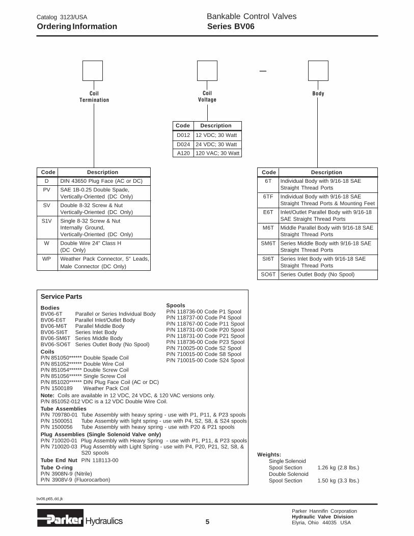
CoilTermination
Body
Code Description
D DIN 43650 Plug Face (AC or DC)
PV SAE 1B-0.25 Double Spade,Vertically-Oriented (DC Only)
SV Double 8-32 Screw & NutVertically-Oriented (DC Only)
S1V Single 8-32 Screw & NutInternally Ground,Vertically-Oriented (DC Only)
W Double Wire 24" Class H(DC Only)
WP Weather Pack Connector, 5" Leads,Male Connector (DC Only)
Code Description
6T Individual Body with 9/16-18 SAEStraight Thread Ports
6TF Individual Body with 9/16-18 SAEStraight Thread Ports & Mounting Feet
E6T Inlet/Outlet Parallel Body with 9/16-18SAE Straight Thread Ports
M6T Middle Parallel Body with 9/16-18 SAEStraight Thread Ports
SM6T Series Middle Body with 9/16-18 SAEStraight Thread Ports
SI6T Series Inlet Body with 9/16-18 SAEStraight Thread Ports
SO6T Series Outlet Body (No Spool)
—
CoilVoltage
Code Description
D012 12 VDC; 30 Watt
D024 24 VDC; 30 Watt
A120 120 VAC; 30 Watt
Hydraulics 6
Parker Hannifin CorporationHydraulic Valve DivisionElyria, Ohio 44035 USA
Bankable Control ValvesCatalog 3123/USA
bvb06i.p65, dd, jk
Series BVB06 Inlets
General Description
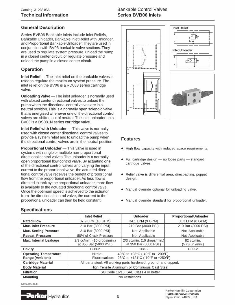
Series BVB06 Bankable Inlets include Inlet Reliefs,Bankable Unloader, Bankable Inlet Relief with Unloader,and Proportional Bankable Unloader. They are used inconjunction with BV06 bankable valve sections. Theyare used to regulate system pressure, unload the pumpin a closed center circuit, or regulate pressure andunload the pump in a closed center circuit.
Operation
Inlet Relief — The inlet relief on the bankable valves isused to regulate the maximum system pressure. Theinlet relief on the BV06 is a RD083 series cartridgevalve.
Unloading Valve — The inlet unloader is normally usedwith closed center directional valves to unload thepump when the directional control valves are in aneutral position. This is a normally open solenoid valvethat is energized whenever one of the directional controlvalves are shifted out of neutral. The inlet unloader on aBV06 is a DS081N series cartridge valve.
Inlet Relief with Unloader — This valve is normallyused with closed center directional control valves toprovide a system relief and to unload the pump whenthe directional control valves are in the neutral position.
Proportional Unloader — This valve is used insystems with single or multiple non-proportionaldirectional control valves. The unloader is a normallyopen proportional flow control valve. By actuating oneof the directional control valves and varying the inputcurrent to the proportional valve; the actuated direc-tional control valve receives the benefit of proportionalflow from the proportional unloader. As less flow isdirected to tank by the proportional unloader, more flowis available to the actuated directional control valve.Once the optimum speed is achieved to the actuatorfrom the directional control valve, the current to theproportional unloader can then be held constant.
Technical Information
Features
• High flow capacity with reduced space requirements.
• Full cartridge design — no loose parts — standardcartridge valves.
• Relief valve is differential area, direct-acting, poppetdesign.
• Manual override optional for unloading valve.
• Manual override standard for proportional unloader.
T
P
T
P
Inlet Unloader
Inlet Relief
Inlet Relief Unloader Proportional UnloaderRated Flow 37.9 LPM (10 GPM) 34.1 LPM (9 GPM) 30.3 LPM (8 GPM)Max. Inlet Pressure 210 Bar (3000 PSI) 210 Bar (3000 PSI) 210 Bar (3000 PSI)Max. Setting Pressure 210 Bar (3000 PSI) Not Applicable Not ApplicableReseat Pressure 80% of Crack Pressure Not Applicable Not ApplicableMax. Internal Leakage 2/3 cc/min. (10 drops/min.) 2/3 cc/min. (10 drops/min.) 82 cc/min.
at 350 Bar (5000 PSI ) at 350 Bar (5000 PSI ) (5 cu. in./min.)Cavity C08-2 C08-2 C09-2Operating Temperature Nitrile: -40°C to +93°C (-40°F to +200°F)Range (Ambient) Fluorocarbon: -23°C to +121°C (-10°F to +250°F)Cartridge Material All parts steel. All working parts hardened, ground, and lapped.Body Material High Tensile Aluminum or Continuous Cast SteelFiltration ISO Code 16/13, SAE Class 4 or betterMounting No restrictions
Specifications

Hydraulics 7
Parker Hannifin CorporationHydraulic Valve DivisionElyria, Ohio 44035 USA
Bankable Control ValvesCatalog 3123/USA
bvb06i.p65, dd, jk
Series BVB06 InletsDimensions
*Inch equivalents for millimeter dimensions are shown in (**)
Inlet Relief
15.9(0.63)
31.8(1.25)
Torque20 N.m.
(180 in.-lbs.)
66.5(2.62) 7.9
(0.31) Typ.71.1
(2.80)7.9
(0.31)13.2
(0.52)
24.6(0.97)
35.1(1.38)
50.8(2.00)
25.4(1.00)
137.7(5.42)
6.8 (0.27) Dia. ThruHoles - 4 Places
Inlet UnloaderTorque Max.
3.4 N.m.(30 in.-lbs.) Torque Max.
20 N.m.(180 in.-lbs.) 15.9
(0.63)
31.8(1.25)
6.8 (0.27) Dia. ThruHoles - 4 Places
66.5(2.62) 7.9
(0.31) Typ.
7.9(0.31)
13.2(0.52)
35.1(1.38)
24.6(0.97)
25.4(1.00)
#6 SAE
50.8(2.00)
43.3(1.70)
129.2(5.08)

Hydraulics 8
Parker Hannifin CorporationHydraulic Valve DivisionElyria, Ohio 44035 USA
Bankable Control ValvesCatalog 3123/USA
bvb06i.p65, dd, jk
Series BVB06 InletsDimensions
*Inch equivalents for millimeter dimensions are shown in (**)
Proportional Inlet
138.4(5.45)
63.5(2.50)
40.6(1.60)
63.8(2.51)
50.8(2.00) 31.8
(1.25)
9.5(0.37)
34.9(1.38)
8.0(0.31)
17.4(0.69)
Inlet Unloader with Relief
Torque Max.20 N.m.
(180 in.-lbs.) 15.9(0.63)
31.8(1.25)
Torque Max.3.4 N.m.
(30 in.-lbs.)
6.8 (0.27) Dia. ThruHoles - 4 Places
66.5(2.62) 7.9
(0.31) Typ.71.1
(2.80)7.9
(0.31)13.2
(0.52)
35.1(1.38)
24.6(0.97)
25.4(1.00)
200.3(7.88)
43.3(1.70)
50.8(2.00)

Hydraulics 9
Parker Hannifin CorporationHydraulic Valve DivisionElyria, Ohio 44035 USA
Bankable Control ValvesCatalog 3123/USA
bvb06i.p65, dd, jk
Series BVB06 Inlets
Code Description Symbol
MR Main Relief
U Unloader
UR Unloader &Relief
PU3 ProportionalUnloader11.3 LPM(3 GPM) with17 Watt Coil
PU6 ProportionalUnloader22.5 LPM(6 GPM) with17 Watt Coil
PU8 ProportionalUnloader30 LPM(8 GPM) with30 Watt Coil
BankableValve
Function ReliefAdjustment
AdjustmentRange
CoilVoltage
CoilWattage
CoilTermination
Ordering Information
Code Description
Omit Unloader Only
20 21-138 Bar (300-2000 PSI)Setting: 121 Bar (1750 PSI)@ 1.6 LPM (6 GPM)
30 103-207 Bar (1500-3000 PSI)Setting: 172 Bar (2500 PSI)@ 1.6 LPM (6 GPM)
Code Description
Omit Main Relief OnlyD012 12 VDCD024 24 VDCA120 120 VAC
Code Description
Omit Main Relief OnlyL 12 Watt (non-Prop)
L 17 Watt (Prop)
H 25 Watt (non-Prop)
H 30 Watt (Prop)
Code Description
Omit Main Relief Only
D DIN 43650 PlugFace (AC or DC)
P Dual Spade (DC Only)
S Double Screw(DC Only)
S1 Single Screw InternallyGround (DC Only)
W Dual Wire (DC Only)
WP Weather Pack(DC Only)
BVB06
T
P
T
P
T
P
T P
DF
1
) (
Code Description
Omit Unloader OnlyCapped with
C Concealedadjustment
Weights:Model BVB06U .48 kg (1.1 lbs.)Model BVB06UR .64 kg (1.4 lbs.)Model BVB06MR .43 kg (0.9 lbs.)Model BVB06PU .48 kg (1.1 lbs.)
Service Parts
Solenoid Coils
BVB06MR-6T (Body for main relief or unloader)
BVB06UR-6T (Body for main relief with unloader)
BVB06PU-6T (Body for proportional unloader)
T P
DF
1
) (
T P
DF
1
) (
OverrideOption
(Unloader)
Code Description
Omit No Override/Proportional
M Flush TypeE Extended Pin
OptionalPressureSetting
Pressure x 10(i.e., 235 = 2350PSI (1.6 Bar)). Allsettings at 11.3LPM (3 GPM).
Code Description
Omit Nitrile
V Fluorocarbon
SAE-6Body
Seals
6T

Hydraulics 10
Parker Hannifin CorporationHydraulic Valve DivisionElyria, Ohio 44035 USA
Bankable Control ValvesCatalog 3123/USA
bv06so.p65, dd, jk
General Description
Bankable Stack-On valves include single and doubleP. O. check valves, single and double crossover reliefvalves, single and double meter-in and meter-out,pressure compensated and non-compensated flowcontrols, single and double reliefs to tank, and singleand double counterbalance valves.
All stack-on valves fit on top of their BV06 bankablespool sections to provide secondary functions. Up totwo different stack-on valves can be installed on top oftheir respective bankable spool sections.
Operation
Stack-on single and double P.O. Check valves are usedin load holding operations. These should only be used inconjunction with a motor spool, a bleeder spool, or aseries spool.
Single and dual crossover reliefs are used to ventshocks that occur at a motor. Any spool can be used inconjunction with these reliefs.
Meter-in and meter-out flow controls are used to controlspeed either to or from the actuator. The pressurecompensated version will provide constant flow regard-less of changes in load or pressure. Any spool can beused in conjunction with these flow controls.
Single and double counterbalances are used in loadholding and over center applications. These should onlybe used in conjunction with a motor spool, a bleederspool, or a series spool.
Specifications
Technical Information
P.C.P.O. Checks Crossover Reliefs Flow Controls Flow Controls Counterbalances
Rated Flow 37.9 LPM (10 GPM) 37.9 LPM (10 GPM) 45.4 LPM (12 GPM) 30.3 LPM (8 GPM) 56.8 LPM (15 GPM)
Max. Operating 350 Bar (5000 PSI) 350 Bar (5000 PSI) 210 Bar (3000 PSI) 210 Bar (3000 PSI) 275 Bar (4000 PSI)Pressure
Max. Leakage @ 1/3 cc/min. 2/3 cc/min. 1/3 cc/min. Not Applicable 1/3 cc/min.Rated Pressure (5 drops/min.) (10 drops/min.) (5 drops/min.) (5 drops/min.)
Oper. Temp. -25°C to +93°C (-40°F to +200°F)Range (Ambient)
Cartridge All parts steel. All working parts hardened, gound, and lapped.Material
Body Material Aluminum Alloy
Porting SAE -6 SAE -6 SAE -6 SAE -6 SAE -6
Filtration ISO Code 16/13, SAE Class 4 or better
Mounting No restrictions
Cavity C08-2 C09-2 C10-2 C10-2 Special
Features
• Cartridge design eliminates leak points.
• High flow capacity with reduced space requirements.
• Reduced cumulative pressure drop.
• Easy to service.
Series BV06 Stack-On Valves
A B

Hydraulics 11
Parker Hannifin CorporationHydraulic Valve DivisionElyria, Ohio 44035 USA
Bankable Control ValvesCatalog 3123/USA
bv06so.p65, dd, jk
Code Description
06 22.7 LPM (6 GPM)Nominal Flow
BankableValve
Size Location
Code Description
A A Port P.O. Check
B B Port P.O. Check
C A & B Port P.O. Check
CrackingPressure
Code Description
Omit 0.3 Bar (5 PSI)
10 0.7 Bar (10 PSI)
20 1.4 Bar (20 PSI)
65 4.4 Bar (65 PSI)
06BV
Technical Information
Ordering Information
Single P.O. Check
Description Part Number
Block 118778-01
Cartridge CVH081P
Piston 118763-00
Double P.O. Check
Description Part Number
Block 118779-01
Cartridge CVH081P
Piston 118764-00
Dimensions
Single P.O. Check Double P.O. Check
Series BV06 Stack-On P.O. Checks
*Inch equivalents for millimeter dimensions are shown in (**)
Weights:BV06-A or BV06-B .51 kg (18 oz.)BV06-C .76 kg (27 oz.)
40.6(1.60)
#6 SAE With22.4 (0.88)Dia. C'Borex 1.3 (0.05)Deep
23.1(0.91)
35.1(1.38)
47.6(1.88)
17.5(0.69)
69.9(2.75)
38.1(1.50)
6.8 (0.27) Dia.Thru - 4 Holes
6.3(0.25)
25.4 (1.00)for SandwichBlock Only
8.6(0.34)
Torque 20 N.m.(180 in.-lbs.)
37.3(1.47)
79.8(3.14)
88.9(3.50)
58.7(2.31) 10.2
(0.40)38.0
(1.50)
17.5(0.69)
6.4(0.25)
25.4(1.00) 6.8 (0.27) Dia.
Thru - 4 Holes
41.3(1.63)
34.9(1.38)
#6 SAE With 22.4 (0.88)Dia. C'Bore x 1.3 (0.50) Deep
37.3(1.47)
113.6(4.47)
Torque 2 N.m.(180 in.-lbs.)

Hydraulics 12
Parker Hannifin CorporationHydraulic Valve DivisionElyria, Ohio 44035 USA
Bankable Control ValvesCatalog 3123/USA
bv06so.p65, dd, jk
Technical Information
Code Description
06 22.7 LPM (6 GPM)Nominal Flow
BankableValve
Size Location
Code Description
D A Port to B Port Crossover Relief
E B Port to A Port Crossover Relief
F A & B Port Crossover Relief
AdjustmentStyle
Code Description
C Concealed Adjust
06BV
Ordering Information
Description Part Number
Block 118780-01
Cartridge RD083C2021-138 Bar (300-2000 PSI)
Cartridge RD083C30104-207 Bar (1500-3000 PSI)
Dimensions
AdjustmentRange
Code Description
15 7-104 Bar (100-1500 PSI)Setting: 52 Bar (750 PSI)@ 11.4 LPM (3 GPM)
30 69-207 Bar (1000-3000 PSI)Setting: 135 Bar (2000 PSI)@ 11.4 LPM (3 GPM)
Series BV06 Stack-On Reliefs
Single Crossover Relief Double Crossover Relief
Single Crossover Relief Double Crossover Relief
19.8(0.78)
44.2(1.74)
76.2(3.00)38.1
(1.50)
25.4(1.00)6.4
(0.25)
#6 SAE With22.4 (0.88)Dia. C'Borex 1.3 (0.05)Deep
6.8 (0.27) Dia.Thru - 4 Holes
19.1(0.75)
47.8(1.88)35.1
(1.38)
17.5(0.69)
6.4(0.25)
A B
Torque 20 N.m.(180 in.-lbs.)
63.5(2.50)38.1
(1.50)
25.4(1.00)6.4
(0.25)12.7
(0.50)
#6 SAE With22.4 (0.88)Dia. C'Borex 1.3 (0.05)Deep
6.8 (0.27) Dia.Thru - 4 Holes
38.4(1.51)
A B
62.7(2.47)
18.5(0.73)
*Inch equivalents for millimeter dimensions are shown in (**)
Description Part Number
Block 118781-01
Cartridge RD083C2021-138 Bar (300-2000 PSI)
Cartridge RD083C30104-207 Bar (1500-3000 PSI)
Weights:BV06-D or BV06-E .51 kg (18 oz.)BV06-F .76 kg (27 oz.)
C
Hydraulics 13
Parker Hannifin CorporationHydraulic Valve DivisionElyria, Ohio 44035 USA
Bankable Control ValvesCatalog 3123/USA
bv06so.p65, dd, jk
Code Description
06 22.7 LPM (6 GPM)Nominal Flow
BankableValve
Size Location
Code Description
NN A Port CounterbalancePP B Port CounterbalanceRR A & B Port Counterbalance
3:1 Pilot Ratio
Code Description
3 3:1 Ratio
06BV
Technical Information
Ordering Information
Counterbalance
Dimensions
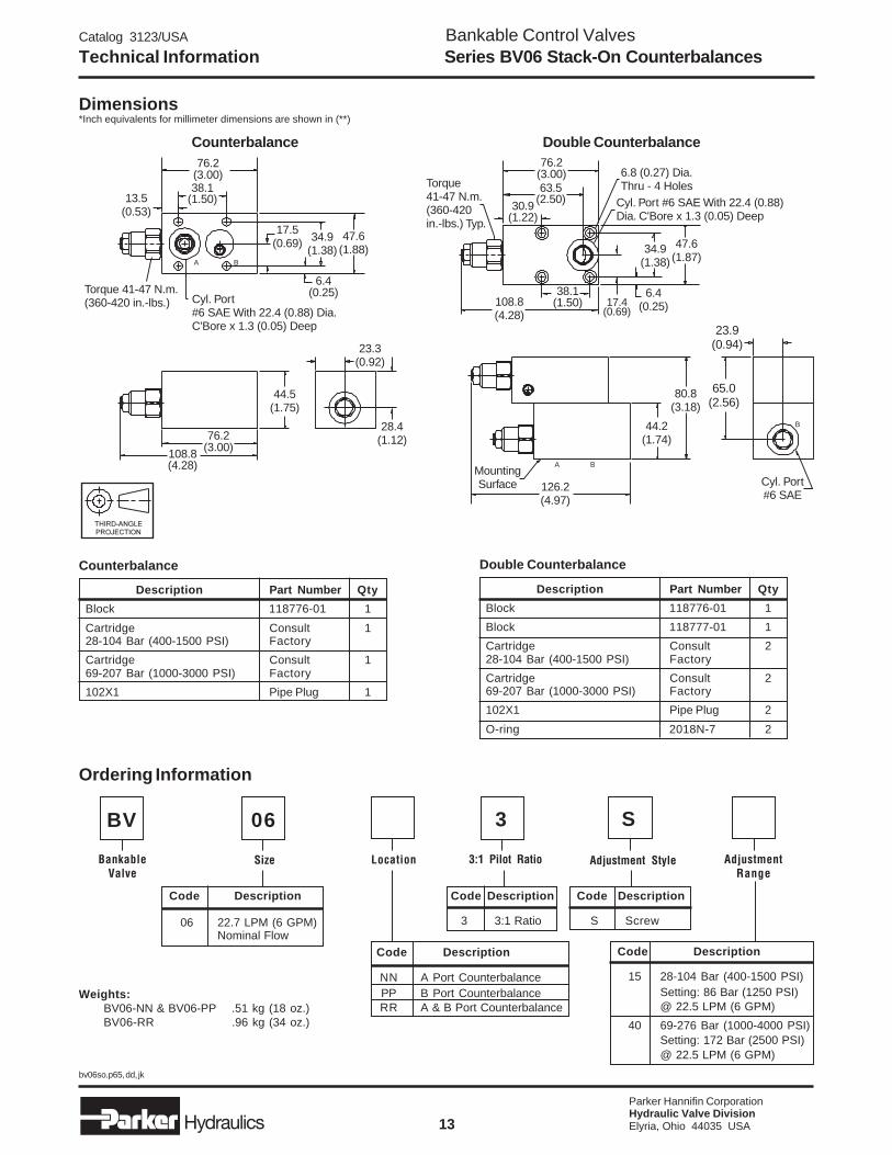
Counterbalance Double Counterbalance
Series BV06 Stack-On Counterbalances
3
AdjustmentRange
Code Description
15 28-104 Bar (400-1500 PSI)Setting: 86 Bar (1250 PSI)@ 22.5 LPM (6 GPM)
40 69-276 Bar (1000-4000 PSI)Setting: 172 Bar (2500 PSI)@ 22.5 LPM (6 GPM)
Adjustment Style
Code Description
S Screw
S
Description Part Number Qty
Block 118776-01 1
Cartridge Consult 128-104 Bar (400-1500 PSI) Factory
Cartridge Consult 169-207 Bar (1000-3000 PSI) Factory
102X1 Pipe Plug 1
Double Counterbalance
Description Part Number Qty
Block 118776-01 1
Block 118777-01 1
Cartridge Consult 228-104 Bar (400-1500 PSI) Factory
Cartridge Consult 269-207 Bar (1000-3000 PSI) Factory
102X1 Pipe Plug 2
O-ring 2018N-7 2
Cyl. Port#6 SAE With 22.4 (0.88) Dia.C'Bore x 1.3 (0.05) Deep
Torque 41-47 N.m.(360-420 in.-lbs.)
76.2(3.00)38.1
(1.50)13.5(0.53)
A B
47.6(1.88)
34.9(1.38)
6.4(0.25)
17.5(0.69)
108.8(4.28)
76.2(3.00)
44.5(1.75)
28.4(1.12)
23.3(0.92)
65.0(2.56)
23.9(0.94)
A B
B
MountingSurface 126.2
(4.97)
44.2(1.74)
80.8(3.18)
Cyl. Port#6 SAE
6.8 (0.27) Dia.Thru - 4 HolesTorque
41-47 N.m.(360-420in.-lbs.) Typ.
Cyl. Port #6 SAE With 22.4 (0.88)Dia. C'Bore x 1.3 (0.05) Deep
30.9(1.22)
63.5(2.50)
76.2(3.00)
47.6(1.87)
34.9(1.38)
17.4(0.69)
6.4(0.25)
38.1(1.50)108.8
(4.28)
*Inch equivalents for millimeter dimensions are shown in (**)
Weights:BV06-NN & BV06-PP .51 kg (18 oz.)BV06-RR .96 kg (34 oz.)

Hydraulics 14
Parker Hannifin CorporationHydraulic Valve DivisionElyria, Ohio 44035 USA
Bankable Control ValvesCatalog 3123/USA
bv06so.p65, dd, jk
Technical Information
Ordering Information
Dimensions
Single P.C. Flow ControlMeter-In or Meter-Out
Double P.C. Flow ControlMeter-In or Meter-Out
Series BV06 Stack-On P.C. Flow Controls
Code Description
06 22.7 LPM (6 GPM)Nominal Flow
BankableValve
Size Location
Code Description
G A Port Meter-In
H B Port Meter-In
J A & B Port Meter-In
K A Port Meter-Out
L B Port Meter-Out
M A & B Port Meter-Out
AdjustmentStyle
Code Description
S Screw Adjust
K Knob Adjust
T Tamper Resistant
06BV
AdjustmentRange
Code Description
050 1.1-3.8 LPM (0.3-1.0 GPM)Setting: @ 1.88 LPM (0.56 GPM)
100 3.0-8.3 LPM (0.8-2.2 GPM)Setting: @ 3.75 LPM (1.0 GPM)
300 7.6-15.1 LPM (2.0-4.0 GPM)Setting: @ 11.25 LPM (3.0 GPM)
600 15.1-30.3 LPM (4.0-8.0 GPM)Setting: @ 22.5 LPM (6.0 GPM)
*Inch equivalents for millimeter dimensions are shown in (**)
69.9(2.75)
50.0(1.97)
17.5(0.69) 35.1
(1.38)
6.4(0.25)
6.4(0.25)
7.9(0.31)
25.4(1.00)
38.1(1.50)149.1
(5.87)
50.0(1.97)
17.5(0.69)
35.1(1.38)
47.8(1.88)
6.4(0.25)
6.4(0.25) 25.4
(1.00)25.4(1.00) 38.1
(1.50)88.9
(3.50)
247.4(9.74)
Weights:BV06-G, BV06-H,BV06-K & BV06-L .54 kg (19 oz.)BV06-J & BV06-M .76 kg (27 oz.)
Single Flow Control
Description Part Number Qty
Block Meter-In 1500168 1
Block Meter-Out 1500167 1
Cartridge FC101 1
Double Flow Control
Description Part Number Qty
Block Meter-In 1500170 1
Block Meter-Out 1500169 1
Cartridge FC101 2

Hydraulics 15
Parker Hannifin CorporationHydraulic Valve DivisionElyria, Ohio 44035 USA
Bankable Control ValvesCatalog 3123/USA
bv06so.p65, dd, jk
Code Description
06 22.7 LPM (6 GPM)Nominal Flow
BankableValve
Size Location
Code Description
G5 A Port Meter-In
H5 B Port Meter-In
J5 A & B Port Meter-In
K5 A Port Meter-Out
L5 B Port Meter-Out
M5 A & B Port Meter-Out
AdjustmentStyle
Code Description
S Screw Adjust
K Knob Adjust
06BV
Technical Information
Ordering Information
Dimensions
Single Flow ControlMeter-In or Meter-Out
Double Flow ControlMeter or Meter-Out
Series BV06 Stack-On Flow Controls
69.9(2.75)
50.0(1.97)
149.1(5.87)
25.4(1.00)
38.1(1.50)
7.9(0.31)
6.4(0.25)
6.4(0.25)
17.5(0.69)
35.1(1.38)
50.0(1.97)
47.8(1.88)
35.1(1.38)
17.5(0.69)
6.4(0.25)25.4
(1.00)25.4
(1.00)
6.4(0.25)
38.1(1.50)88.9
(3.50)247.4(9.74)
*Inch equivalents for millimeter dimensions are shown in (**)
Single Flow Control
Description Part Number Qty
Block Meter-In 1500167 1
Block Meter-Out 1500168 1
Cartridge FV101 1
Dual Flow Control
Description Part Number Qty
Block Meter-In 1500169 1
Block Meter-Out 1500170 1
Cartridge FV101 2
Weights:BV06-G5, BV06-H5,BV06-K5 & BV06-L5 .54 kg (19 oz.)BV06-J5 & BV06-M5 .76 kg (27 oz.)

Hydraulics 16
Parker Hannifin CorporationHydraulic Valve DivisionElyria, Ohio 44035 USA
Bankable Control ValvesCatalog 3123/USA
bv06so.p65, dd, jk
Series BV06
BankableValves
Size
06BV
Code Description
06 22.7 LPM(6 GPM)Nominal Flow
Code Description Symbol
P1 30.0 LPM (8 GPM) Max. Flow*without Malfunction; Parallel Circuit Only
P4 22.7 LPM (6 GPM) Max. Flow*without Malfunction; Parallel Circuit Only
P11 26.5 LPM (7 GPM) Max. Flow*without Malfunction; Parallel Circuit Only
P20 22.7 LPM (6 GPM) Max. Flow*without Malfunction; Parallel Circuit Only
P21 22.7 LPM (6 GPM) Max. Flow*without Malfunction; Parallel Circuit Only
P23 30.0 LPM (8 GPM) Max. Flow*without Malfunction; Parallel Circuit Only
S2 26.5 LPM (7 GPM) Max. Flow*without Malfunction; Series Circuit Only
S8 26.5 LPM (7 GPM) Max. Flow*without Malfunction; Series Circuit Only
S24 26.5 LPM (7 GPM) Max. Flow*without Malfunction; Series Circuit Only
Spools
*At 70 PSI ∆P
Code Description Symbol
Omit Std InletNo ReliefNo Unloader
MR Main Relief
U Unloader
UR Unloader &Relief
PU3 ProportionalUnloader11.3 LPM(3 GPM) with17 Watt Coil
PU6 ProportionalUnloader22.5 LPM(6 GPM) with17 Watt Coil
PU8 ProportionalUnloader30.0 LPM(8 GPM) with30 Watt Coil
Note: Maximum of six spools per assembly. For each additional spoolrepeat spool option after stack-on option.
Note: Standard setting 2500 PSI @ 6 GPM, with screwadjustments on all relief cartridges.Standard setting 1000 PSI @ crack, with screwadjustments on all counterbalance cartridges.
Valve Assemblies with or without Stack-On Options
T
P
T
P
T
P
T P
DF
1) (
T P
DF
1) (
T P
DF
1) (
T
P
A
P
B
T
A
P
B
T
) )) )
A
P
B
T
A
P
B
T
A
P
B
T
A
P
B
T
A
P
B
T
A
P
B
T
Ordering Information
Service Parts
BodiesBV06-6T Parallel or Series Individual BodyBV06-E6T Parallel Inlet/Outlet BodyBV06-M6T Parallel Middle BodyBV06-SI6T Series Inlet BodyBV06-SM6T Series Middle BodyBV06-SO6T Series Outlet Body (No Spool)
SpoolsP/N 118736-00 Code P1 SpoolP/N 118737-00 Code P4 SpoolP/N 118767-00 Code P11 SpoolP/N 118731-00 Code P20 SpoolP/N 118731-00 Code P21 SpoolP/N 118736-00 Code P23 SpoolP/N 710025-00 Code S2 SpoolP/N 710015-00 Code S8 SpoolP/N 710015-00 Code S24 Spool
CoilsP/N 851050****** Double Spade CoilP/N 851052****** Double Wire CoilP/N 851054****** Double Screw CoilP/N 851056****** Single Screw CoilP/N 851020****** DIN Plug Face Coil (AC or DC)P/N 1500189 Weather Pack Coil
Note: Coils are available in 12 VDC, 24 VDC, & 120 VAC versions only.P/N 851052-012 VDC is a 12 VDC Double Wire Coil.
Tube AssembliesP/N 709780-01 Tube Assembly with heavy spring - use
with P1, P11, & P23 spoolsP/N 1500051 Tube Assembly with light spring - use with
P4, S2, S8, & S24 spoolsP/N 1500056 Tube Assembly with heavy spring - use
with P20 & P21 spools
Plug Assemblies (Single Solenoid Valve only)P/N 710020-01 Plug Assembly with Heavy Spring - use
with P1, P11, & P23 spoolsP/N 710020-02 Plug Assembly with Light Spring - use with
P4, P20, P21, S2, S8, & S20 spools
Tube End Nut P/N 118113-00
SealsP/N 2013N-7 (Between sections)P/N 2018N-7 (Between stacks)
A
P
B
T
InletFunction

Hydraulics 17
Parker Hannifin CorporationHydraulic Valve DivisionElyria, Ohio 44035 USA
Bankable Control ValvesCatalog 3123/USA
bv06so.p65, dd, jk
Weights:Single SolenoidSpool Section 1.26 kg (2.8 lbs.)Double SolenoidSpool Section 1.50 kg (3.3 lbs.)
Code Description
Omit Nitrile
V Fluorocarbon
Seals
Code Description
D DIN 43650 Plug Face (AC or DC)
PV SAE 1B-0.25 Double Spade,Vertically-Oriented (DC Only)
SV Double 8-32 Screw & NutVertically-Oriented (DC Only)
S1V Single 8-32 Screw & NutInternally Ground,Vertically-Oriented (DC Only)
W Double Wire 24" Class H(DC Only)
WP Weather Pack Connector, 5" Leads,Male Connector (DC Only)
Code Description
D012 12 VDC; 30 Watt
D024 24 VDC; 30 Watt
A120 120 VAC; 30 Watt
Code Description Symbol
A A PortP.O. Check
B B PortP.O. Check
C A & B PortP.O. Checks
D A Port to B PortCrossover Relief
E B Port to A PortCrossover Relief
F A & B Ports DualCrossover Relief
G A Port Meter-InFlow ControlPressure Comp.
H B Port Meter-InFlow ControlPressure Comp.
J A & B Port Meter-InFlow ControlPressure Comp.
K A Port Meter- OutFlow ControlPressure Comp.
L B Port Meter-OutFlow ControlPressure Comp.
Note: Maximum of two stack-ons per spool section.
* Meter-In is from the valve to the actuator. Meter-Out is from the actuator to the valve.
Code Description Symbol
M A & B Port Meter-OutPressure Comp.
G5 A Port Meter-InFlow ControlNon-Pressure Comp.
H5 B Port Meter-InFlow ControlNon-Pressure Comp.
J5 A & B Port Meter-InFlow ControlNon-Pressure Comp.
K5 A Port Meter-OutFlow controlNon-Pressure Comp.
L5 B Port Meter-OutFlow ControlNon-Pressure Comp.
M5 A & B PortMeter-OutNon-Pressure Comp.
NN A PortCounterbalance56.8 LPM (15 GPM) Max.
PP B PortCounterbalance56.8 LPM (15 GPM) Max.
RR A & B PortCounterbalance56.8 LPM (15 GPM) Max.
A B
A B
A B
A B
A B
A B
A B
A B
A B
A B
A B
A B
A B
A B
A B
A B
A B
A B
A B
A B
A B
Series BV06Ordering Information
CoilTermination
Stack-On Options* CoilVoltage

Hydraulics 18
Parker Hannifin CorporationHydraulic Valve DivisionElyria, Ohio 44035 USA
Bankable Control ValvesCatalog 3123/USA
bv06assy.p65, dd, jk
Series BV06
Number of Spool Sections 1 2 3 4 5 6Dimensions L1 L2 L1 L2 L1 L2 L1 L2 L1 L2 L1 L2Individual-Parallel 47.8 92.2or Series (1.88) (3.63)Parallel 96.8 141.2 145.8 190.3 194.8 239.3 243.8 288.3 325.9 370.3
(3.81) (5.56) (5.74) (7.49) (7.67) (9.42) (9.60) (11.35) (12.83) (14.58)Parallel, Parallel with Inlet 80.8 125.2 129.8 174.2 178.8 223.3 227.8 272.3 276.9 321.3 329.2 373.6Relief, Inlet Unloader with (3.18) (4.93) (5.11) (6.86) (7.04) (8.79) (8.97) (10.72) (10.90) (12.65) (12.96) (14.71)ReliefSeries 113.9 158.4 162.9 207.4 212.0 256.4 261.0 305.4 310.0 354.5
(4.49) (6.24) (6.42) (8.17) (8.35) (10.10) (10.28) (12.03) (12.21) (13.96)Series with Inlet 80.8 125.2 149.2 191.4 196.0 240.4 244.9 289.4 294.8 338.5 343.0 387.5Relief (3.18) (4.93) (5.79) (7.54) (7.72) (9.47) (9.65) (11.40) (11.58) (13.33) (13.51) (15.26)Mounting KitIndividual-Parallel or Series BV06-MK1Parallel BV06-MK2 BV06-MK3 BV06-MK4 BV06-MK5 BV06-MK6Parallel with Inlet Relief,Inlet Unloader with Relief BV06-MK1A BV06-MK2A BV06-MK3A BV06-MK4A BV06-MK5A BV06-MK6ASeries BV06-MK1B BV06-MK2B BV06-MK3B BV06-MK4B BV06-MK5B BV06-MK6BSeries with Inlet Relief BV06-MK1C BV06-MK2C BV06-MK3C BV06-MK4C BV06-MK5C BV06-MK6C
Assembled Valves
*Inch equivalents for millimeter dimensions are shown in (**)
1/4-20 TieRod 9 N.m.(80 in.-lbs.)Torque
BodyE6T
O-Ring Plate 118750-00O-Ring 2013N-7 (2013V-7)
BodyM6T Body
E6T
38.1(1.50)
49.0(1.93)
49.0(1.93)
L1L2
8.1(0.32)
Mounting Kit,O/R Plate, O/R's,Tie Rods, Nuts,Washers, Brackets
118749-00 Foot31.8
(1.25)Typ.
3.0(0.12)
28.5(1.12)
15.8(0.63)
118113-00 NutFinger TightTorque
36X7SZ Lockwasher16X107SZ Nut
Tube2.0 N.m.(180 in.-lbs.)Torque
213.4(8.40)
25.4(1.00)
6.4(0.25)
71.1(2.80)
213.4(8.40)
25.4(1.00)
0.25(6.4)
71.1(2.8)
OutletPort PlateBV06-SO6T
BodySM6T
BodySM6T
BodySI6T
16.0(0.63)
MountingKit
6.8(0.27)
Hydraulics 19
Parker Hannifin CorporationHydraulic Valve DivisionElyria, Ohio 44035 USA
Bankable Control ValvesCatalog 3123/USA
bv06assy.p65, dd, jk
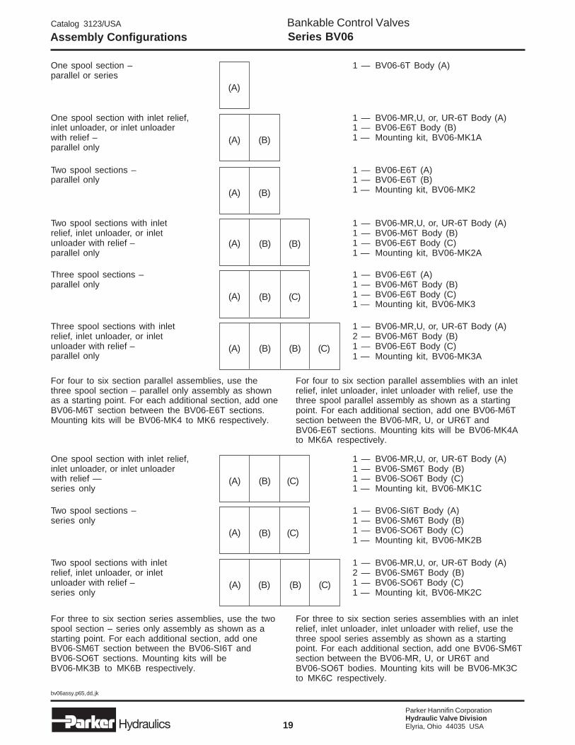
Series BV06Assembly Configurations
One spool section –parallel or series
1 — BV06-6T Body (A)
Three spool sections –parallel only
One spool section with inlet relief,inlet unloader, or inlet unloaderwith relief –parallel only
(B)(A)
(B)(A)
(A)
(B)(A)
(B)(A)
(B)
(B)(A) (C)
(C)(B)
Three spool sections with inletrelief, inlet unloader, or inletunloader with relief –parallel only
Two spool sections with inletrelief, inlet unloader, or inletunloader with relief –parallel only
Two spool sections –parallel only
1 — BV06-MR,U, or, UR-6T Body (A)1 — BV06-E6T Body (B)1 — Mounting kit, BV06-MK1A
1 — BV06-E6T (A)1 — BV06-E6T (B)1 — Mounting kit, BV06-MK2
1 — BV06-MR,U, or, UR-6T Body (A)1 — BV06-M6T Body (B)1 — BV06-E6T Body (C)1 — Mounting kit, BV06-MK2A
1 — BV06-E6T (A)1 — BV06-M6T Body (B)1 — BV06-E6T Body (C)1 — Mounting kit, BV06-MK3
1 — BV06-MR,U, or, UR-6T Body (A)2 — BV06-M6T Body (B)1 — BV06-E6T Body (C)1 — Mounting kit, BV06-MK3A
For four to six section parallel assemblies, use thethree spool section – parallel only assembly as shownas a starting point. For each additional section, add oneBV06-M6T section between the BV06-E6T sections.Mounting kits will be BV06-MK4 to MK6 respectively.
For four to six section parallel assemblies with an inletrelief, inlet unloader, inlet unloader with relief, use thethree spool parallel assembly as shown as a startingpoint. For each additional section, add one BV06-M6Tsection between the BV06-MR, U, or UR6T andBV06-E6T sections. Mounting kits will be BV06-MK4Ato MK6A respectively.
One spool section with inlet relief,inlet unloader, or inlet unloaderwith relief —series only
Two spool sections –series only
(B)(A) (C)
(B)(A) (C)
1 — BV06-SI6T Body (A)1 — BV06-SM6T Body (B)1 — BV06-SO6T Body (C)1 — Mounting kit, BV06-MK2B
1 — BV06-MR,U, or, UR-6T Body (A)1 — BV06-SM6T Body (B)1 — BV06-SO6T Body (C)1 — Mounting kit, BV06-MK1C
(B)(A) (C)(B)
Two spool sections with inletrelief, inlet unloader, or inletunloader with relief –series only
1 — BV06-MR,U, or, UR-6T Body (A)2 — BV06-SM6T Body (B)1 — BV06-SO6T Body (C)1 — Mounting kit, BV06-MK2C
For three to six section series assemblies, use the twospool section – series only assembly as shown as astarting point. For each additional section, add oneBV06-SM6T section between the BV06-SI6T andBV06-SO6T sections. Mounting kits will beBV06-MK3B to MK6B respectively.
For three to six section series assemblies with an inletrelief, inlet unloader, inlet unloader with relief, use thethree spool series assembly as shown as a startingpoint. For each additional section, add one BV06-SM6Tsection between the BV06-MR, U, or UR6T andBV06-SO6T bodies. Mounting kits will be BV06-MK3Cto MK6C respectively.

Hydraulics 20
Parker Hannifin CorporationHydraulic Valve DivisionElyria, Ohio 44035 USA
Bankable Control ValvesCatalog 3123/USA
bv06assy.p65, dd, jk
Series BV06Stacking Kit and Configurations
Stack Mounting Kit Matrix
Single Stack Valve: Choose stack valve in column to left. Follow chart to column labeled Single Stack.Choose stack mounting kit part number.Double Stack Valves: Choose bottom stack from column at left. Follow chart over to top stack valve. Choosestack mounting kit part number.
Stacking Kits
Stack valve mounting kits are furnished complete with socket head cap screws, lock washers, and o-ring seals.Please contact the factory for combinations not shown in the chart for application approval.
Stack Valve Component Data
Alternate Method of Determining Stack Valve Mounting Kits:Determine Cap Screw Minimum Length (L) using formula below and choose next longest cap screw and associatedmounting kit from the Cap Screw Data chart:
Single Stack Cap Screw Minimum Length (L) =Stack Valve Height (H) - Stack Valve Counterbore (CB) + 9.5 mm (0.38")
Double Stack Cap Screw Minimum Length (L) =Bottom Stack Valve Height (H) + Top Stack Valve Height (H) - Top Stack Valve Counterbore (CB) + 9.5 mm (0.38")
Bottom or Single Stack Top Stack
Stacking Kit P/N Single DoubleNitrile O-rings Single and Double Single Flow and Counterbalance Crossover
Fluorocarbon O-rings Single Stack P.O. Check Double Control (A or B) Relief
Single and Double BV06-SK1 Not Applicable Not Applicable Not Applicable Not ApplicableP.O. Check BV06-SK1VSingle and Double BV06-SK1 BV06-SK4A Not Applicable BV06-SK5A BV06-SK7AFlow Control BV06-SK1V BV06-SK4AV BV06-SK5AV BV06-SK7AVSingle Counter- BV06-SK1A BV06-SK3A BV06-SK3A Not Applicable Not Applicablebalance (A or B) BV06-SK1AV BV06-SK3AV BV06-SK3AVDouble BV06-SK3A Not Applicable Not Applicable Not Applicable Not ApplicableCounterbalance BV06-SK3AVSingle Crossover BV06-SK1A BV06-SK3A BV06-SK3A BV06-SK4A Not ApplicableRelief (A or B) BV06-SK1AV BV06-SK3AV BV06-SK3AV BV06-SK4AVDouble Crossover BV06-SK2A BV06-SK6A BV06-SK6A BV06-SK7A Not ApplicableRelief BV06-SK2AV BV06-SK6AV BV06-SK6AV BV06-SK7AV
Single and Single and Single Double Single Cross- DoubleStack Valve Double P.O. Double Flow Counterbalance Counterbalance over Relief Crossover
Check Control (A or B) (A or B) Relief
Stack Valve 37.3 mm 50.0 mm 44.4 mm 80.8 mm 44.2 mm 62.7 mmHeight (H) (1.47") (1.97") (1.75") (3.18") (1.74") (2.47")
Stack Valve 7.6 mm 20.3 mm 6.6 mm 7.6 mm 6.4 mm 11.2 mmCounterbore (0.30") (0.80") (0.26") (0.30") (0.25") (0.44")(CB)
Cap Screw 44.4 mm 50.8 mm 63.5 mm 88.9 mm 95.2 mm 101.6 mm 108.0 mm 114.3 mmLength (1.75") (2.00") (2.50") (3.50") (3.75") (4.00") (4.25") (4.50")
MountingKit Number BV06-SK1 BV06-SK1A BV06-SK2A BV06-SK3A BV06-SK4A BV06-SK5A BV06-SK6A BV06-SK7Aw/ Nitrile
MountingKit Number BV06-SK1V BV06-SK1AV BV06-SK2AV BV06-SK3AV BV06-SK4AV BV06-SK5AV BV06-SK6AV BV06-SK7AVw/ Fluorocarbon
Hydraulics 21
Parker Hannifin CorporationHydraulic Valve DivisionElyria, Ohio 44035 USA
Bankable Control ValvesCatalog 3123/USA
bv06assy.p65, dd, jk
Series BV06Ordering Information
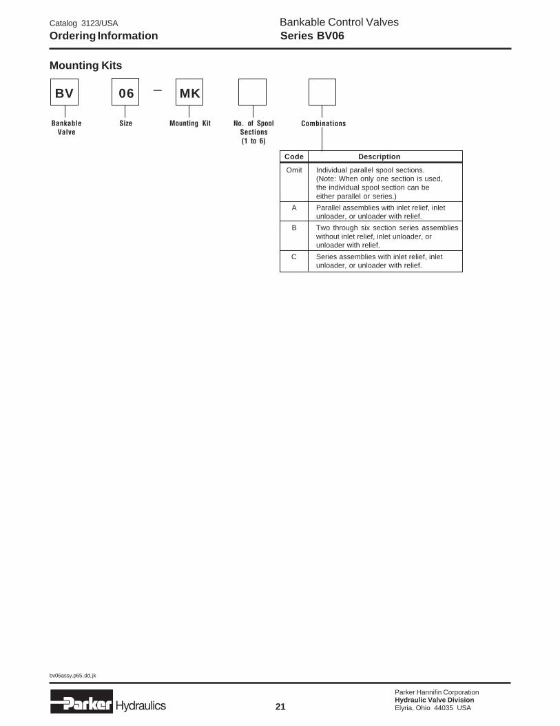
Mounting Kits
BankableValve
Size Mounting Kit Combinations
Code Description
Omit Individual parallel spool sections.(Note: When only one section is used,the individual spool section can beeither parallel or series.)
A Parallel assemblies with inlet relief, inletunloader, or unloader with relief.
B Two through six section series assemblieswithout inlet relief, inlet unloader, orunloader with relief.
C Series assemblies with inlet relief, inletunloader, or unloader with relief.
MK06BV
No. of SpoolSections(1 to 6)
—

Hydraulics 22
Parker Hannifin CorporationHydraulic Valve DivisionElyria, Ohio 44035 USA
Bankable Control ValvesCatalog 3123/USA
bv18.p65, dd, jk
Series BV18
General Description
Series BV18 Bankables are 2 or 3 position, 4-way,directional control valves. They provide a spool valvethat can be used either individually or in multiple spoolbanks. BV18 bankable valves have auxiliary bankingsections that can be mounted to provide auxiliaryfunctions such as an inlet relief or unloading function. Inaddition, stack-on sections can be mounted on thecylinder port face of the BV18 bankable valve spoolsections to provide additional functions such ascrossover reliefs, cylinder port reliefs, P.O. checks, flowcontrols, and counterbalances. BV18 bankable valvesare also available with two different proportional spooloptions, and can be used to create custom, multi-functional circuits.
Operation
The spool is shifted from its center position by eitherenergizing one of the solenoids, applying air or hydrau-lic pressure, or by shifting the lever. Three-positionspring centered and two-position spring offset valvesare available. The spools of the proportional BV18bankable valves are shifted by energizing one of thesolenoid coils. The travel of the spool is in directproportion to the amperage applied to the solenoid coil.The more amperage that is applied, the further thespool shifts until it is at full travel. As long as the coilamperage is held steady, the spool will hold its position.As the amperage decreases, the spool will travel backtowards its neutral position. Metering notches on thespool vary the pressure drop across the spool. As thespool travels, the flow varies. Once the spool is held ina given position, the pressure drop across the meteringnotches of the spool determines the flow.
Technical Information
Features
• High flow capacity with reduced space requirements.
• High back pressure; all ports withstand maximumworking pressure.
• Precision machined valve body is made from hightensile cast iron.
• A five chamber style body ensures high pressureoperation.
• Six different spool styles are available; all are four landspools for smoother shifting.
• Available operators include single or double solenoids,lever, hydraulic pilot, or air pilot.
• All solenoids are a one-piece coil featuring numerousvoltages and terminations.
A
P
B
T

Hydraulics 23
Parker Hannifin CorporationHydraulic Valve DivisionElyria, Ohio 44035 USA
Bankable Control ValvesCatalog 3123/USA
bv18.p65, dd, jk
Series BV18
BV18 BV18 ProportionalNominal Flow 30-90 LPM (8-24 GPM) Up to 22.5 LPM (6 GPM)(at 70 PSI ∆∆∆∆∆P) depending on spool depending on spoolMaximum Inlet & Parallel: 350 Bar (5000 PSI) Inlet Parallel: 350 Bar (5000 PSI) InletTank Pressure 210 Bar (3000 PSI) Tank 210 Bar (3000 PSI) Tank
Series: 210 Bar (3000 PSI) Inlet & TankPorting SAE -8 SAE -8Maximum Internal #1 Spool: 22.9 cc per land/min. #81 Spool: 22.9 cc per land/min.Leakage (1.40 cu. in. per land/min.) (1.40 cu. in. per land/min.)(3000 PSI) #2 Spool: 47.2 cc per land/min. #82 Spool: 22.9 cc per land/min.(110 SSU oil) (2.88 cu. in. per land/min.) (1.40 cu. in. per land/min.)
#9 Spool: 24.4 cc per land/min.(1.49 cu. in. per land/min.)
#11 Spool: 87.4 cc per land/min.(5.33 cu. in. per land/min.)
Hysteresis Not Applicable 8%Frequency Not Applicable 200 Hz PWM
Air Pressure Crack - 3.5 Bar (50 PSIA) Not Applicableto Shift Full Shift - 6.9 Bar (100 PSIA) Not ApplicableMaximum AirPressure 10.3 Bar (150 PSIA) Not ApplicableAir Piston Area 506 sq. mm (.785 sq. in.) Not ApplicableAir Piston Stroke 3.4 mm (.135 in.) Not Applicable
Hydraulic Pressure Crack - 15.2 Bar (200 PSI )to Shift Full Shift- 20.7 Bar (300 PSI) Not ApplicableMax. HydraulicPilot Pressure 210 Bar (3000 PSI) Not ApplicableHydraulic PistonArea 198 sq. mm (.307 sq. in.) Not ApplicableHydraulic PistonStroke 3.4 mm (.135 in.) Not ApplicableOperatingTemperature
Nitrile: -40°C to +93°C (-40°F to +200°F) Nitrile: -40°C to +93°C (-40°F to +200°F)
Range (Ambient)Fluorocarbon: -32°C to +121°C (-25°F to +250°F) Fluorocarbon: -32°C to +121°C (-25°F to +250°F)
Material Body: Precision machined and Body: Precision machined andhoned from cast iron honed from cast iron
Spool: Hardened and ground steel Spool: Hardened and ground steelFiltration ISO Code 16/13, ISO Code 16/13,
SAE Class 4 or better SAE Class 4 or betterMounting Position No restrictions No restrictionsMounting Type Line mounted Line mounted
Specifications

Hydraulics 24
Parker Hannifin CorporationHydraulic Valve DivisionElyria, Ohio 44035 USA
Bankable Control ValvesCatalog 3123/USA
bv18.p65, dd, jk
Series BV18Construction Views
BV18-H
Double Hydraulic Pilot
BV18-HA (A Side) - BV18-HB (B Side)
Single Hydraulic Pilot
BV18SA (A Side) - BV18SB (B Side) BV18S
Single Solenoid Double Solenoid
BV18-P
Double Air Pilot
BV18-PA (A Side) - BV18-PB (B Side)
Single Air Pilot
BV18LA (A Side) - BV18LB (B Side) BV18DA (A Side) - BV18DB (B Side)
Lever Detented Lever
Valve Body With Spool Proportional Valve Body With Spool

Hydraulics 25
Parker Hannifin CorporationHydraulic Valve DivisionElyria, Ohio 44035 USA
Bankable Control ValvesCatalog 3123/USA
bv18.p65, dd, jk
Series BV18Performance Curves
Switching Limits
Differential Pressure
Notes:
1. Refer to shift limit curves for flow capabilities ofindividual spools.
2. Curves were generated using 110 SSUhydraulic oil.
Flow Path
P-A P-B A-T B-T P-T
S 1 1 1 2 2
P 2 1 1 2 2 2
O 4 1 1 1 3
O 9 1 1 2 2 5
L 11 1 1 2 2
20 1* 1** 4** 3**
*20 Spool, De-energized **20 Spool, Energized
Notes:
1. Shift limits apply to all actuator types.
2. Unless otherwise specified, all curves were generatedusing solenoid actuators at 90% of rated with voltage.
3. The 4 spool maximum working pressure drop cannotexceed 136 Bar (2000 PSI) from inlet to work port using24 watt coils, and 204 Bar (3000 PSI) using 30 watt coils.
4. The 1 spool and the 11 spool should be used with 30watt coils when working pressure exceeds 238 Bar(3500 PSI ).
5. All valves tested using 110 SSU oil.
6. Maximum flow for the 2 spool is 45 LPM (12 GPM) usingAC coils.
7. All AC coils must be 25 watt rated.
0244 8 16 20GPM
9015 30
12
45 60 75LPM0
20.4
17.0
13.6
10.2
6.8
3.4
Bar
5
421
3
PSI23.8350
300
250
200
150
100
50
Pre
ssur
e D
rop
(P
)∆
Flow (Q)
0104 1381500 2000
1732500
69351000500
24220735003000
276 3114000 4500
3455000
Operating Pressure
0
5 18.9
10 37.9
15 56.8
20
25GPM
75.7
94.6LPM
Flow
(Q)
BarPSI
1
4
9
4, 9
11
2 20

Hydraulics 26
Parker Hannifin CorporationHydraulic Valve DivisionElyria, Ohio 44035 USA
Bankable Control ValvesCatalog 3123/USA
bv18.p65, dd, jk
Series BV18
Solenoid Code Nominal Voltage/Hz In Rush Amps Holding Amps Wattage
D10 10 VDC — 3.0 24
D10H 10 VDC — 3.5 30
D12 12 VDC — 2.0 24
D12H 12 VDC — 2.5 30
D24 24 VDC — 1.0 24
D24H 24 VDC — 1.25 30
A120H 120 VAC/60 Hz 2.00 0.49 25
A120H 110 VAC/50 Hz 2.10 0.58 27
A240H 240 VAC/60 Hz 1.00 0.26 25
A240H 220 VAC/60 Hz 1.05 0.31 27
DC COILS
Pressure Response Full ShiftSpool Coil Type Pull In Drop Out Drop Out
1 12 VDC, 24 Watt (12) 65 ms 40 ms 239 ms
1 12 VDC, 30 Watt (12H) 42 ms 40 ms 239 ms
2 12 VDC, 24 Watt (12) 174 ms 40 ms 140 ms
2 12 VDC, 30 Watt (12H) 155 ms 40 ms 144 ms
4 12 VDC, 24 Watt (12) 44 ms 40 ms 294 ms
4 12 VDC, 30 Watt (12H) 40 ms 40 ms 292 ms
9 12 VDC, 24 Watt (12) 426 ms 40 ms 340 ms
9 12 VDC, 30 Watt (12H) 191 ms 40 ms 431 ms
11 12 VDC, 24 Watt (12) 45 ms 40 ms 233 ms
11 12 VDC, 30 Watt (12H) 38 ms 40 ms 257 ms
20 12 VDC, 24 Watt (12) 69 ms 20 ms 23 ms
20 12 VDC, 30 Watt (12H) 47 ms 20 ms 27 ms
AC COILS
Pressure Response Full ShiftSpool Coil Type Pull In Drop Out Drop Out
1 120 VAC/60 Hz, (11H) 12 ms 20 ms 279 ms
1 110 VAC/50 Hz, (11H) 12 ms 20 ms 279 ms
2 120 VAC/60 Hz, (11H) 12 ms 20 ms 278 ms
2 110 VAC/50 Hz, (11H) 12 ms 20 ms 278 ms
4 120 VAC/60 Hz, (11H) 12 ms 20 ms 278 ms
4 110 VAC/50 Hz, (11H) 12 ms 20 ms 278 ms
9 120 VAC/60 Hz, (11H) 16 ms 20 ms 242 ms
9 110 VAC/50 Hz, (11H) 16 ms 20 ms 242 ms
11 120 VAC/60 Hz, (11H) 16 ms 20 ms 249 ms
11 110 VAC/50 Hz, (11H) 16 ms 20 ms 249 ms
20 120 VAC/60 Hz, (11H) 17 ms 20 ms 236 ms
20 110 VAC/50 Hz, (11H) 17 ms 20 ms 236 ms
Solenoid Code Nominal Voltage/Hz Watts Step Response Ramp Time
D012 12 VDC 24 96 ms Up to 3 seconds
D024 24 VDC 24 96 ms Up to 3 seconds
Solenoid Coil Specifications
Technical Information
Typical Solenoid Response Times
Proportional Solenoid Coil Specifications
Hydraulics 27
Parker Hannifin CorporationHydraulic Valve DivisionElyria, Ohio 44035 USA
Bankable Control ValvesCatalog 3123/USA
bv18.p65, dd, jk
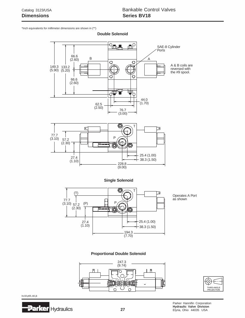
Series BV18Dimensions
*Inch equivalents for millimeter dimensions are shown in (**)
A & B coils arereversed withthe #9 spool.
SAE-8 CylinderPorts
AB
Double Solenoid
77.7(3.10) 57.2
(2.30)
27.4(1.10)
228.8(9.00)
25.4 (1.00)38.3 (1.50)
T
P
149.3(5.90)
133.2(5.20)
66.6(2.60)
66.6(2.60)
62.5(2.50)
44.0(1.70)
76.7(3.00)
Single Solenoid
77.7(3.10) 57.2
(2.30)
27.4(1.10) 38.3 (1.50)
194.3(7.70)
25.4 (1.00)
T
P
(T)
(P)
Operates A Portas shown
Proportional Double Solenoid
247.3(9.74)

Hydraulics 28
Parker Hannifin CorporationHydraulic Valve DivisionElyria, Ohio 44035 USA
Bankable Control ValvesCatalog 3123/USA
bv18.p65, dd, jk
Series BV18Dimensions
*Inch equivalents for millimeter dimensions are shown in (**)
Lever(Operates Port A as shown)
66.6(2.60)
133.2(5.30)
66.6(2.60)
149.3(5.90)
7.1(0.30)62.5
(2.50)
76.7(3.00)
Detented Lever(Operates Port A as shown)
163.2(6.40)
25.4(1.00)38.3
(1.50)
27.4(1.10)
57.2(2.30)
77.7(3.10)
T
P
SAE-8 CylinderPorts

Hydraulics 29
Parker Hannifin CorporationHydraulic Valve DivisionElyria, Ohio 44035 USA
Bankable Control ValvesCatalog 3123/USA
bv18.p65, dd, jk
Series BV18Dimensions
*Inch equivalents for millimeter dimensions are shown in (**)
Double Hydraulic Pilot
A & B pilot arereversed withthe #9 spool.
BA
66.6(2.60)
133.2(5.30)
66.6(2.60)
7.1(0.30)62.5
(2.50)76.7
(3.00)
T
P
(T)
(P)77.7
(3.10) 57.2(2.30)
27.4(1.10)
173.3(6.80)
25.4(1.00)
38.3(1.50)
Single Hydraulic Pilot(Operates A Port as shown)
T(T)
(P) P77.7
(3.10) 57.2(2.30)
27.4(1.10)
166.6(6.60)
25.4(1.00)
38.3(1.50)
SAE-8 CylinderPorts

Hydraulics 30
Parker Hannifin CorporationHydraulic Valve DivisionElyria, Ohio 44035 USA
Bankable Control ValvesCatalog 3123/USA
bv18.p65, dd, jk
Series BV18Dimensions
*Inch equivalents for millimeter dimensions are shown in (**)
133.4(5.30)
7.1(0.30)
66.7(2.60)
66.7(2.60)
76.7(3.00)
149.3(5.90)
62.5(2.50)
A B
P
T
195.6(7.70)
27.4(1.10)
77.7(3.10)
38.4(1.50)
57.2(2.30)
(P)
(T)
25.4(1.00)
P
T
177.7(7.00)
27.4(1.10)
(P)
(T)
77.7(3.10)
38.4(1.50)
57.2(2.30)
25.4(1.00)
Single Air Pilot
Double Air Pilot
SAE-8 CylinderPorts
Hydraulics 31
Parker Hannifin CorporationHydraulic Valve DivisionElyria, Ohio 44035 USA
Bankable Control ValvesCatalog 3123/USA
bv18.p65, dd, jk
Series BV18
BodyType
BankableValve
Size Operators Spools CoilTermination
18BV
Ordering Information
CoilVoltage
CoilWattage
Code Description
18 68.1 LPM (18 GPM)Nominal Flow
Code Description
S Dual Solenoids
SA Single Solenoid on A
SB Single Solenoid on B
LA Lever on A
LB Lever on B
DA Lever w/detent on A
DB Lever w/detent on B
H Dual Hydraulic Pilot
HA Hydraulic Pilot on A
HB Hydraulic Pilot on B
P Dual Air Pilot
PA Air Pilot on A
PB Air Pilot on B
F Proportional; Dual Solenoids
FA Proportional; Single Solenoid on A
FB Proportional; Single Solenoid on B
Code Description
1 Closed Center; 68.1 LPM (18 GPM)Nominal; Parallel
2 Open Center 90.8 LPM (24 GPM)Nominal; Series or Parallel
4 Motor; 90.8 LPM (24 GPM); Parallel
9 Tandem; 68.1 LPM (15 GPM);Series
11 Bleeder; 56.8 LPM (15 GPM); Parallel
20 Two Position; 64.3 LPM (17 GPM);Parallel
81 Closed Center; Closed Transition;Proportional 22.7 LPM (6 GPM)
82 Motor; Meter-In; Proportional22.7 LPM (6 GPM)
Code Description
Omit Non-Solenoid
D DIN 43650 Plug Face (AC or DC)
P SAE 1B-0.25 Double Spade(DC Only)
S Double 8-32 Screw & Nut(DC & non-Proportional Only)
S1 Single 8-32 Screw & Nut;Internally Ground(DC & non-Proportional Only)
W Double Wire 24" Class H(DC & non-Proportional Only)
WP Weather Pack Connector,5" Leads, Male Connector(DC & non-Proportional Only)
Code Description
Omit Non-Solenoid
D10 10 VDC
D12 12 VDC
D24 24 VDC
A120 120 VAC (60 Hz)110 VAC (50 Hz)
A240 240 VAC (60 Hz)220 VAC (50 Hz)
Code Description
Omit Non-Solenoid
L 24 Watt DC Only
H 30 Watt - DC(& Proportional)24 Watt - AC
Code Description
Omit Without Inlet/Outlet -Spool Section Only
T Without Inlet/Outlet -Spool Section Only withAdded Tank Port forTank Port Reliefs
Spool Assemblies (Individual Sections)
Weights:Double Solenoid 2.93 kg (6 lbs.)Single Solenoid 2.03 kg (4.5 lbs.)
Note: Proportional coils are available in12 VDC and 24 VDC voltages with DINand Dual Spade coils only.
— —

Hydraulics 32
Parker Hannifin CorporationHydraulic Valve DivisionElyria, Ohio 44035 USA
Bankable Control ValvesCatalog 3123/USA
bv18.p65, dd, jk
Series BV18
Service Parts
BodiesBV18-W Individual Body - Series or ParallelBV18-WT Individual Body - Series or Parallel
with added Tank Port for Tank Port Reliefs
Coils1550090-10 10 VDC, 24 Watt Dual Spade Coil1550090-12 12 VDC, 24 Watt Dual Spade Coil1550090-24 24 VDC, 24 Watt Dual Spade Coil1550091-10 10 VDC, 30 Watt Dual Spade Coil1550091-12 12 VDC, 30 Watt Dual Spade Coil1550091-24 24 VDC, 30 Watt Dual Spade Coil1550092-10 10 VDC, 24 Watt Dual Wire Coil1550092-12 12 VDC, 24 Watt Dual Wire Coil1550092-24 24 VDC, 24 Watt Dual Wire Coil1550093-10 10 VDC, 30 Watt Dual Wire Coil1550093-12 12 VDC, 30 Watt Dual Wire Coil1550093-24 24 VDC, 30 Watt Dual Wire Coil1550094-10 10 VDC, 24 Watt DIN Plug Face Coil697228 120 VAC 60 Hz/110 VAC 50 Hz
25 Watt DIN Plug Face Coil1550094-12 12 VDC, 24 Watt DIN Plug Face Coil697229 240 VAC 60 Hz/220 VAC 50 Hz
25 Watt DIN Plug Face Coil1550094-24 24 VDC, 24 Watt DIN Plug Face Coil1550095-10 10 VDC, 30 Watt DIN Plug Face Coil1550095-12 12 VDC, 30 Watt DIN Plug Face Coil1550095-24 24 VDC, 30 Watt DIN Plug Face Coil1550177-12 12 VDC, 30 Watt Double Spade Proportional Coil1550177-24 24 VDC, 30 Watt Double Spade Proportional Coil1550178-12 12 VDC, 30 Watt Double Wire Proportional Coil1550178-24 24 VDC, 30 Watt Double Wire Proportional Coil1550174-12 12 VDC, 30 Watt DIN Plug Face Proportional Coil1550174-24 24 VDC, 30 Watt DIN Plug Face Proportional Coil
Ordering Information
Tube AssembliesP/N 697632 AC Tube AssemblyP/N 697633 DC Tube AssemblyP/N 697188 DC Proportional Tube Assembly
SpoolsP/N 697601 #1 SpoolP/N 697602 #2 SpoolP/N 697604 #4 SpoolP/N 1302128 #9 SpoolP/N 697611 #11 SpoolP/N 697620 #20 SpoolP/N 1210011 #81 Proportional SpoolP/N 1210012 #82 Proportional Spool
Seals2013N-9 Body Seals (two required per Body)3907N-9 Tube/End Cap Seal (one required per
Tube/End Cap)

Hydraulics 33
Parker Hannifin CorporationHydraulic Valve DivisionElyria, Ohio 44035 USA
Bankable Control ValvesCatalog 3123/USA
bv18i.p65, dd, jk
Series BV18 Inlets
General DescriptionBankable Inlet Reliefs, Bankable Unloaders, BankableReliefs with Unloaders, and Proportional BankableUnloaders are used in conjunction with BV18 bankablevalve sections. They are used to regulate systempressure, unload the pump in a closed center circuit,or regulate pressure and unload the pump in a closedcenter circuit.
OperationInlet Relief — The inlet relief on the bankable valvesis used to regulate the maximum system pressure. Theinlet relief on the BV18 is a RDH103 series cartridgevalve.Unloading Valve — The inlet unloader is normallyused with closed center directional valves to unloadthe pump when the directional control valves are in aneutral position. This is a normally open solenoid valvethat is energized whenever one of the directionalcontrol valves are shifted out of neutral. The inletunloader on a BV18 is a DSH101NR series cartridgevalve.Inlet Relief with Unloader — This valve is normallyused with closed center directional control valves toprovide a system relief and to unload the pump whenthe directional control valves are in the neutral posi-tion.Proportional Unloader — This valve is used insystems with single or multiple non-proportionaldirectional controls valves. The unloader is a normallyopen proportional flow control valve. By actuating oneof the directional control valves and varying the inputcurrent to the proportional valve; the actuated direc-tional control valve receives the benefit of proportionalflow from the proportional unloader. As less flow isdirected to tank by the proportional unloader, moreflow is available to the actuated directional controlvalve. Once the optimum speed is achieved to theactuator from the directional control valve, the currentto the proportional unloader can then be held con-stant.
Technical Information
Features
• High flow capacity with reduced space requirements.
• Full cartridge design — no loose parts — standardcartridge valves.
• Relief valve is differential area, direct-acting, poppetdesign.
• Manual override optional for unloading valve.
• Manual override standard for proportional unloader.
T
P
Inlet Relief Unloader Proportional UnloaderRated Flow 75 LPM (20 GPM) 56.3 LPM (15 GPM) 52.5 LPM (14 GPM)Max. Inlet Pressure 375 Bar (5500 PSI) 350 Bar (5000 PSI) 210 Bar (3000 PSI)Max. Setting Pressure 350 Bar (5000 PSI) Not Applicable Not ApplicableReseat Pressure 80% of Crack Pressure Not Applicable Not ApplicableMax. Internal Leakage 2/3 cc/min. (10 drops/min.) 2/3 cc/min. (10 drops/min.) 82 cc/min. (5 cu. in./min.)
at 350 Bar (5000 PSI ) at 350 Bar (5000 PSI )Cavity C10-2 C10-2 C12-2Operating Temperature Nitrile: -40°C to +93°C (-40°F to +200°F)Range (Ambient) Fluorocarbon: -23°C to +121°C (-10°F to +250°F)Cartridge Material All parts steel. All working parts hardened, ground, and lapped.Body Material High Tensile Aluminum or Continuous Cast SteelFiltration ISO Code 16/13, SAE Class 4 or betterMounting No restrictions
Specifications

Hydraulics 34
Parker Hannifin CorporationHydraulic Valve DivisionElyria, Ohio 44035 USA
Bankable Control ValvesCatalog 3123/USA
bv18i.p65, dd, jk
Series BV18 InletsDimensions
*Inch equivalents for millimeter dimensions are shown in (**)
Inlet ReliefApprox. 153.7
(6.05) 83.1(3.30) 27.0
(1.10)19.1(0.80)
64.1(2.50) 38.3
(1.50)
52.7(2.10)
8.4(0.30)17.2
(0.70)42.3
(1.70)
5.3(0.20)
Inlet Unloading/ReliefApprox. 246.3
(9.70)27.0
(1.10) 8.1(0.30)
Torque19-21 N.m.
(35-40 ft.-lbs.)Torque19-21 N.m.
(35-40 ft.-lbs.)
Torque19-21 N.m.
(35-40 ft.-lbs.)
Torque19-21 N.m.
(35-40 ft.-lbs.)
5.3(0.20)
103.2(4.10)
37.2(1.50)21.3
(0.80)42.5
(1.70)
8.3(0.30)
38.1(1.50)
52.7(2.10)
64.0(2.50)
Inlet Unloading Proportional Inlet
Approx. 155.4(6.10)
27.0(1.10) 7.9
(0.30)
8.4(0.30)
38.3(1.50)
17.2(0.70)
42.3(1.70)
21.1(0.80)
83.1(3.30)
64.0(2.50)
5.3(0.20)
Approx. 221.1(8.70)8.0
(0.30)
52.7(2.10)
43.2(1.70)
8.4(0.30) 5.3
(0.20)8.0
(0.30) 42.0(1.70)21.2
(0.80)27.0
(1.10)42.3
(1.70)
Standard Inlet
64.0(2.50)43.5
(1.70)
13.7(0.50)
38.4(1.50)
51.6(2.00)
Inlet Port Plate
25.4(1.00)
64.0(2.50)
23.5(0.90) 15.3
(0.60)
5.3(0.20)
17.2(0.70)21.2
(0.80)42.3(1.70)
5.2(0.20)
52.7(2.10) 37.8
(1.50)

Hydraulics 35
Parker Hannifin CorporationHydraulic Valve DivisionElyria, Ohio 44035 USA
Bankable Control ValvesCatalog 3123/USA
bv18i.p65, dd, jk
Series BV18 InletsOrdering Information
Code Description
SI No Relief or Unloader
MR Main Relief
U Unloader
UR Unloader & Relief
PU Proportional Unloader
BankableValve
Body Material Function ReliefAdjustment
OverrideOption
(Unloader)
CoilVoltage
Coil Wattage Coil Termina-tion
Code Description
Omit Unloader Only
K Knob Adjust
S Screw Adjust
T Tamper Resistant
Code Description
Omit Unloader Only10 7-69 Bar (100-1000 PSI)
Setting: 34 Bar (500 PSI)@ 45 LPM (12 GPM)
20 35-138 Bar (500-2000 PSI)Setting: 68 Bar (1000 PSI)@ 45 LPM (12 GPM)
30 69-207 Bar (1000-3000 PSI)Setting: 103 Bar (1500 PSI)@ 45 LPM (12 GPM)
50 138-345 Bar (2000-5000 PSI)Setting: 138 Bar (2000 PSI)@ 45 LPM (12 GPM)
Code Description
Omit No Override/Proportional
M Flush Type
E Extended Pin
Code Description
Omit Main Relief Only
D10 10 VDC
D12 12 VDC
D24 24 VDC
A120 120 VAC (60 Hz)110 VAC (50 Hz)
Code Description
Omit Main Relief Only
L 20 Watt (non-Prop)
42 Watt (Prop)
Code Description
Omit Main Relief Only
D DIN 43650 Plug
Face (AC or DC)
P Dual Spade (DC Only)
W Dual Wire (DC Only)
WP Weather Pack (DC Only)
*Note: If system pressure does notexceed 210 Bar (3000 PSI), aluminumbodies can be used. Higher pressuresrequire steel bodies.
AdjustmentRange
Code Description
Omit Aluminum 207 Bar Max.(3000 PSI Max.)
H* Steel 345 Bar Max.(5000 PSI Max.)
BV18
Service PartsInlet Relief RDH103***Inlet Unloader DSH101NProportional Unloader DF122N14Solenoid CoilsS10LD************ DIN (Hirschman) Coil - Non ProportionalS10LP************ Double Shade Coil - Non ProportionalS10LW************Double Wire Coil - Non ProportionalS10LWT********** Double Wire Coil with weather pack connector
- Non ProportionalP/N 851058****** DIN (Hirschman) Coil - ProportionalP/N 851060****** Double Shade Coil - ProportionalP/N 851062****** Double Wire Coil - ProportionalP/N 852855****** Double Wire Coil with weather pack connector
- ProportionalSeals2013N-9 Body Seal2019N-9 Body Seal
Weights:BV18SI - 0.3 kg (12 oz.)BV18MR - 0.5 kg (17 oz.)BV18U - 1.1 kg (37 oz.)BV18UR - 1.5 kg (54 oz.)BV18PU - 1.2 kg (40 oz.)

Hydraulics 36
Parker Hannifin CorporationHydraulic Valve DivisionElyria, Ohio 44035 USA
Bankable Control ValvesCatalog 3123/USA
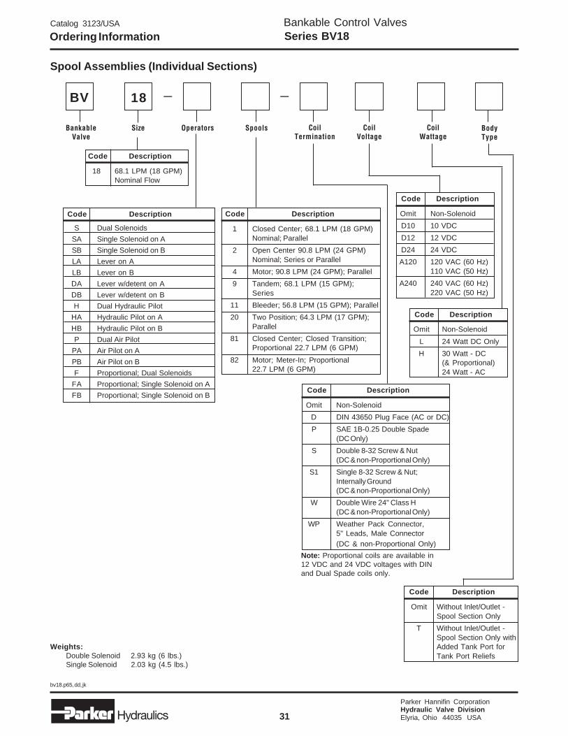
bv18so.p65, dd, jk
Series BV18 Stack-OnsTechnical Information
General Description
Bankable Stack-On valves are available on the BV18.These include single and double P.O. check valves,single and double crossover relief valves, single anddouble meter-in and meter-out, pressure compensatedand non-compensated flow controls, single and doublereliefs to tank, and single and double counterbalancevalves.
All stack-on valves fit on top of their respective Bank-able spool sections to provide secondary functions. Upto two different stack-on valves can be installed on topof their respective bankable spool sections.
Operation
Stack-On single and double P.O. check valves areused in load holding operations. These should only beused in conjunction with a motor spool, a bleederspool, or a series spool.
Single and double reliefs to tank are used to vent anyshocks that occur at the cylinder to tank. Single anddual crossover reliefs are used to vent shocks thatoccur at a motor. Any spool can be used in conjunctionwith these reliefs.
Meter-in and meter-out flow controls are used tocontrol speed either to or from the actuator. Thepressure compensated version will provide constantflow regardless of changes in load or pressure. Anyspool can be used in conjunction with these flowcontrols.
Single and double counterbalances are used in loadholding and over center applications. These shouldonly be used in conjunction with a motor spool, ableeder spool, or a series spool.
Features
• Cartridge design eliminates leak points.
• High flow capacity with reduced space requirements.
• Reduced cumulative pressure drop.
• Easy to service.
SpecificationsTank Port & P.C.
P.O. Checks Crossover Reliefs Flow Controls Flow Controls Counterbalances
Rated Flow 79.5 LPM (21 GPM) 75.7 LPM (20 GPM) 45.4 LPM (12 GPM) 30.3 LPM (8 GPM ) 56.8 LPM (15 GPM)
Max. Operating 350 Bar 350 Bar 210 Bar 210 Bar 275 BarPressure (5000 PSI) (5000 PSI) (3000 PSI) (3000 PSI) (4000 PSI)
Max. Leakage @ 1/3 cc/min. 2/3 cc/min. 1/3 cc/min. Not Applicable 1/3 cc/min.Rated Pressure (5 drops/min.) (10 drops/min.) (5 drops/min.) (5 drops/min.)
Oper. Temp. -25°C to +93°C (-40°F to +200°F)Range (Ambient)
CartridgeMaterial All parts steel. All working parts hardened, ground and lapped.
Body Material Aluminum alloy for 210 Bar (3000 PSI) or continuous cast steel for over 210 Bar (3000 PSI)
Porting SAE -8 SAE -8 SAE -8 SAE -8 SAE -8
Filtration ISO Code 16/13, SAE Class 4 or better
Mounting No restrictions
Cavity C10-2 C10-2 C10-2 C10-2 Special
A B
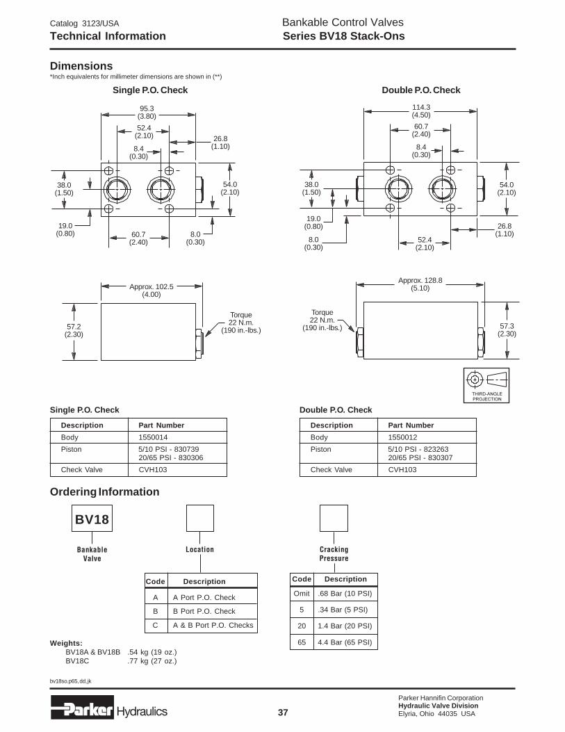
Hydraulics 37
Parker Hannifin CorporationHydraulic Valve DivisionElyria, Ohio 44035 USA
Bankable Control ValvesCatalog 3123/USA
bv18so.p65, dd, jk
Series BV18 Stack-OnsTechnical Information
Location CrackingPressure
BankableValve
Code Description
A A Port P.O. Check
B B Port P.O. Check
C A & B Port P.O. Checks
Code Description
Omit .68 Bar (10 PSI)
5 .34 Bar (5 PSI)
20 1.4 Bar (20 PSI)
65 4.4 Bar (65 PSI)
BV18
Dimensions
Ordering Information
38.0(1.50)
19.0(0.80) 8.0
(0.30)
54.0(2.10)
26.8(1.10)
52.4(2.10)
95.3(3.80)
8.4(0.30)
60.7(2.40)
57.2(2.30)
Torque22 N.m.
(190 in.-lbs.)
Approx. 102.5(4.00)
38.0(1.50)
19.0(0.80)
8.0(0.30)
52.4(2.10)
26.8(1.10)
54.0(2.10)
8.4(0.30)
60.7(2.40)
114.3(4.50)
Approx. 128.8(5.10)
57.3(2.30)
Torque22 N.m.
(190 in.-lbs.)
*Inch equivalents for millimeter dimensions are shown in (**)
Single P.O. Check Double P.O. Check
Single P.O. Check Double P.O. Check
Description Part Number
Body 1550014
Piston 5/10 PSI - 83073920/65 PSI - 830306
Check Valve CVH103
Description Part Number
Body 1550012
Piston 5/10 PSI - 82326320/65 PSI - 830307
Check Valve CVH103
Weights:BV18A & BV18B .54 kg (19 oz.)BV18C .77 kg (27 oz.)

Hydraulics 38
Parker Hannifin CorporationHydraulic Valve DivisionElyria, Ohio 44035 USA
Bankable Control ValvesCatalog 3123/USA
bv18so.p65, dd, jk
Series BV18 Stack-OnsTechnical Information
Code Description
3 3.1
Dimensions
Ordering Information
Location Pilot RatioBankableValve
Size
Code Description
N A Port Counterbalance
75.5 LPM (0-20 GPM)
NN A Port Counterbalance
56.8 LPM (0-15 GPM)
P B Port Counterbalance
75.7 LPM (0-20 GPM)
PP B Port Counterbalance
56.8 LPM (0-15 GPM)
R A & B Port Counterbalance
75.7 LPM (0-20 GPM)
RR A & B Port Counterbalance
56.8 LPM (0-15 GPM)
BV
AdjustmentStyle
AdjustmentRange
Code Description
15 27.3-102.0 Bar(400-1500 PSI)
40 68.0-272.1 Bar(1000-4000 PSI)
Code Description
S Screw
38.0(1.50)
8.0(0.30)
19.0(0.80)
114.1(4.50)
60.8(2.40)
2.1(54.0)
44.6(1.80)
52.4(2.10)
8.4(0.30)
57.2(2.30)
Approx. 156.2 (6.20)
57.2(2.30)
Torque41-47 N.m.
(360-420 in.-lbs.)
38.0(1.50)
Approx. 234.1(9.20)
150.0(5.90)
60.8(2.40)
44.6(1.80) 8.0
(0.30)
19.0(0.80)
54.0(2.10)
52.4(2.10)
8.4(0.30)
S318
*Inch equivalents for millimeter dimensions are shown in (**)
Single Counterbalance Double Counterbalance
Code Description
18 68.1 LPM (18 GPM)Nominal Flow
Single Counterbalance
Description Part Number
Body (N or P) 1550030
Body (NN or PP) 1550148
Counterbalance Valves Consult Factory
Double Counterbalance
Description Part Number
Body (R) 1550028
Body (RR) 1550146
Counterbalance Valves Consult Factory
Weights:BV18N, BV18NN,BV18P & BV18PP .74 kg (26 oz.)BV18R & BV18RR 1.25 kg (44 oz.)

Hydraulics 39
Parker Hannifin CorporationHydraulic Valve DivisionElyria, Ohio 44035 USA
Bankable Control ValvesCatalog 3123/USA
bv18so.p65, dd, jk
Series BV18 Stack-OnsTechnical Information
Dimensions
Ordering Information
Code Description
18 68.1 LPM (18 GPM)Nominal Flow
LocationBankableValve
Size
Code Description
D A Port to B PortCrossover Relief
E B Port to A PortCrossover Relief
F A Port & B PortCrossover Relief
T A Port to Tank ReliefW B Port to Tank ReliefY A & B Port to Tank Relief
BV
AdjustmentStyle
AdjustmentRange
Code Description
10 7-69 Bar (100-1000 PSI)Setting: 35 Bar (500 PSI)@ 11.4 LPM (10 GPM)
20 35-138 Bar (500-2000 PSI)Setting: 69 Bar (1000 PSI)@ 11.4 LPM (10 GPM)
30 69-207 Bar (1000-3000 PSI)Setting: 104 Bar (1500 PSI)@ 11.4 LPM (10 GPM)
50 138-345 Bar (2000-5000 PSI)Setting: 173 Bar (2500 PSI)@ 11.4 LPM (10 GPM)
Code Description
S Screw Adjust
K Knob Adjust
18
*Inch equivalents for millimeter dimensions are shown in (**)
Single Port Relief Double Cross-Over ReliefSingle Cross-Over ReliefDouble Port Relief
Description Part Number
Body 1550034
Relief Valves RDH103
Description Part Number
Body 1550036
Relief Valves RDH103
Description Part Number
Body 1550017
Relief Valves RDH103
Description Part Number
Body 1550018
Relief Valves RDH103
Weights:BV18D, BV18E,BV18T, BV18W .54 kg (19 oz.)BV18F, BV18Y .79 kg (28 oz.)
Single Crossover Relief/Single Port Relief Double Crossover Relief
Double Port Relief
57.2(2.30)
54.0(2.10)
89.7(3.50)60.8
(2.40) 38.0(1.50)
Approx. 260.3(10.30)
52.4(2.10)
8.4(0.30)
8.0(0.30)
14.5(0.60)
19.0(0.80)
54.0(2.10)
8.4(0.30)
9.7(0.40)
19.0(0.80)
8.0(0.30)
80.2(3.20)
52.4(2.10)
38.0(1.50)
57.2(2.30)
Approx. 250.8(9.90)
57.2(2.30)
Approx. 165.5(6.50)
Torque22 N.m.
(190 in.-lbs.)
54.0(2.10)
8.4(0.30) 38.0
(1.50)
19.0(0.80)
9.7(0.40)52.4
(2.10)60.6
(2.40)80.2(3.20)
8.0(0.30)
Torque22 N.m.
(190 in.-lbs.)

Hydraulics 40
Parker Hannifin CorporationHydraulic Valve DivisionElyria, Ohio 44035 USA
Bankable Control ValvesCatalog 3123/USA
bv18so.p65, dd, jk
Series BV18 Stack-OnsTechnical Information
Dimensions
Ordering Information
Location*BankableValve
Size
BV
AdjustmentStyle
AdjustmentRange
Code Description
050 1.13-3.75 LPM(0.3-1.0 GPM)
100 2.81-8.25 LPM(0.75-2.2 GPM)
300 7.5-15.0 LPM(2.0-4.0 GPM)
600 15.1-30.3 LPM(4.0-8.0 GPM)
Code Description
S Screw Adjust
K Knob Adjust
T Tamper Resistant
Code Description
G A Port Meter-In
H B Port Meter-In
J A & B Port Meter-In
K A Port Meter-Out
L B Port Meter-Out
M A & B Port Meter-Out
18
*Inch equivalents for millimeter dimensions are shown in (**)
Code Description
18 68.1 LPM (18 GPM)Nominal Flow
Single — Meter-In P.C.Flow Controls
Double — Meter-Out P.C.Flow Controls
Single — Meter-Out P.C.Flow Controls
Double — Meter-In P.C.Flow Controls
Description Part Number
Body 1550026
Flow Control FC101
Description Part Number
Body 1550020
Flow Control FC101
Description Part Number
Body 1550024
Flow Control FC101
Description Part Number
Body 1550023
Flow Control FC101
Weights:BV18G, BV18H,BV18K, BV18L .65 kg (23 oz.)BV18J, BV18M .79 kg (28 oz.)
Double P.C. Flow ControlMeter-In/Meter-Out
54.1(2.10)
60.8(2.40)
8.4(0.30)
19.0(0.80)
38.0(1.50)
8.1(0.30)
26.8(1.10)52.4
(2.10)
114.3(4.50)
Approx. 182.9(7.20)
Meter-Out 22.1(0.90)
Single P.C. Flow ControlMeter-In/Meter-Out
19.0(0.80) 38.0
(1.50)
26.8(1.10)
60.8(2.40)
8.1(0.30)
54.1(2.10)
96.3(3.80)
Approx. 129.3(5.10)
8.4(0.30)
52.4(2.10)
Meter-In57.2
(2.30)Torque 22 N.m.
(190 in.-lbs.)22.1
(0.90)Torque22 N.m.
(190 in.-lbs.)57.2(2.30)
16.4(0.60)
*Meter-in is from the valve to the actuator. Meter-Out is from the actuator to the valve.

Hydraulics 41
Parker Hannifin CorporationHydraulic Valve DivisionElyria, Ohio 44035 USA
Bankable Control ValvesCatalog 3123/USA
bv18so.p65, dd, jk
Series BV18 Stack-OnsTechnical Information
Location* AdjustmentStyle
BankableValve
Size
Code Description
G5 A Port Meter-In
H5 B Port Meter-In
J5 A & B Port Meter-In
K5 A Port Meter-Out
L5 B Port Meter-Out
M5 A & B Port Meter-Out
Code Description
S Screw Adjust
K Knob Adjust
BV
Ordering Information
18
Code Description
18 68.1 LPM (18 GPM)Nominal Flow
Dimensions*Inch equivalents for millimeter dimensions are shown in (**)
Single — Meter-In Double — Meter-OutSingle — Meter-OutDouble — Meter-In
Description Part Number
Body 1550024
Flow Control FV101
Description Part Number
Body 1550023
Flow Control FV101
Description Part Number
Body 1550026
Flow Control FV101
Description Part Number
Body 1550020
Flow Control FV101
Weights:BV18G5, BV18H5,BV18K5, BV18L5 .65 kg (23 oz.)BV18J5, BV18M5 .79 kg (28 oz.)
Double — Meter-In/Meter-Out
54.1(2.10)
60.8(2.40)
8.4(0.30)
19.0(0.80)
38.0(1.50)
8.1(0.30)
26.8(1.10)52.4
(2.10)
114.3(4.50)
Approx. 182.9(7.20)
Meter-Out 22.1(0.90)
Single — Meter-In/Meter-Out
19.0(0.80) 38.0
(1.50)
26.8(1.10)
60.8(2.40)
8.1(0.30)
54.1(2.10)
96.3(3.80)
Approx. 129.3(5.10)
8.4(0.30)
52.4(2.10)
Meter-In57.2
(2.30)Torque 22 N.m.
(190 in.-lbs.)22.1
(0.90)Torque22 N.m.
(190 in.-lbs.)57.2(2.30)
16.4(0.60)
*Meter-in is from the valve to the actuator. Meter-Out is from the actuator to the valve.

HydraulicsParker Hannifin CorporationHydraulic Valve DivisionElyria, Ohio 44035 USA
Bankable Control ValvesCatalog 3123/USA
bv18ep.p65, dd, jk
Dimensions*Inch equivalents for millimeter dimensions are shown in (**)
Technical Information
Ordering Information
BankableValve
Material End Plate Variation
EPBV18
Code Description
Omit Aluminum
S Steel
Code Description
1 P & T Porting
2 Turn Around Plate
25.9(1.00)
77.2(3.00)
42.3(1.70)15.3
(0.60)
5.8(0.20)
17.2(0.70)
21.5(0.80) 5.2
(0.20)
52.7(2.10)
64.5(2.50) 13.7
(0.50)
38.4(1.50)
End PlatesBV18* — EP1
BV18* — EP2
#8 SAE
13.7(0.50)
38.4(1.50)
64.0(2.50)39.5
(1.60)
52.7(2.10)
5.2(0.20)
42.3(1.70)
21.2(0.80)
17.2(0.70)
5.3(0.20)
15.3(0.60)
76.7(3.00)
#4 SAE
25.4(1.00)
—
Weight: 0.3 kg (12 oz.)
Series BV18 Valve Assembly
42

HydraulicsParker Hannifin CorporationHydraulic Valve DivisionElyria, Ohio 44035 USA
Bankable Control ValvesCatalog 3123/USA
bv18ep.p65, dd, jk
Notes

HydraulicsParker Hannifin CorporationHydraulic Valve DivisionElyria, Ohio 44035 USA
Bankable Control ValvesCatalog 3123/USA
bv18ep.p65, dd, jk
Ordering Information
BankableValves
Size
18BV
Code Description
18 67.5 LPM (18 GPM)
Valve Assemblies with or without Stack-On Options
Code Description
Omit 210 Bar (3000 PSI)
H 350 Bar (5000 PSI)
InletFunction
Operators Spools
Note: Specify pressure times 100.Example: 20 x 100 = 2000 PSI.
Code Description Symbol
S Dual Solenoids
SA Single Solenoid on A
SB Single Solenoid on B
LA Lever on A
LB Lever on B
DA Lever w/Detent on A
DB Lever w/Detent on B
H Dual Hydraulic Pilots
Code Description Symbol
HA Hydraulic Pilot on A
HB Hydraulic Pilot on B
P Dual Air Pilots
PA Air Pilot on A
PB Air Pilot on B
F Proportional;Dual Solenoids
FA Proportional;Single Solenoid on A
FB Proportional;Single Solenoid on B
Code Description Symbol
1 Closed Center; 68.1 LPM (18 GPM)Nominal; Parallel
2 Open Center 90.8 LPM (24 GPM)Nominal; Series or Parallel
4 Motor; 90.8 LPM (24 GPM);Parallel
9 TandemCenter; 68.1 LPM(15 GPM); Series
11 Bleeder; 56.8 LPM (15 GPM);Parallel
20 Two Position; 64.3 LPM (17 GPM);Parallel
81 Closed Center; Closed Transition;Proportional 22.7 LPM (6 GPM)
82 Motor; Meter-In; Proportional22.7 LPM (6 GPM)
Note: Each bank must consist of all parallel spools or all series spools.
A
P
B
T
A
P
B
T
A
P
B
T
A
P
B
T
A
P
B
T
) )
A
P
B
T
() ()()
()
() ()()
()
PressureRating
Code Description Symbol
SI No ReliefNo Unloader
MR Main Relief
U Unloader
UR Unloader &Relief
PU8 ProportionalUnloader52.5 LPM(14 GPM) with17 Watt Coil
T
P
T
P
T
P
T
P
T P
DF
1
) (
Series BV18 Valve Assembly
43

HydraulicsParker Hannifin CorporationHydraulic Valve DivisionElyria, Ohio 44035 USA
Bankable Control ValvesCatalog 3123/USA
bv18ep.p65, dd, jk
Ordering Information
Stack-On Options Coil Termination
Code Description Symbol
A A PortP.O. Check
B B PortP.O. Check
C A & B PortP.O. Checks
D A Port to B PortCrossover Relief
E B Port to A PortCrossover Relief
F A & B Ports DualCrossover Relief
G A Port Meter-InFlow ControlPressure Comp.
H B Port Meter-InFlow ControlPressure Comp.
J A & B Port Meter-InFlow ControlPressure Comp.
K A Port Meter- OutFlow ControlPressure Comp.
L B Port Meter-OutFlow ControlPressure Comp.
M A & B Port Meter-OutPressure Comp.
G5 A Port Meter-InFlow ControlNon-Pressure Comp.
H5 B Port Meter-InFlow ControlNon-Pressure Comp.
J5 A & B Port Meter-InFlow ControlNon-Pressure Comp.
K5 A Port Meter-OutFlow controlNon-Pressure Comp.
L5 B Port Meter-OutFlow ControlNon-Pressure Comp.
M5 A & B PortMeter-OutNon-Pressure Comp.
Note: Maximum of two stack-ons per spool section.
Code Description Symbol
N A PortCounterbalance
P B PortCounterbalance
R A & B PortCounterbalance
NN A PortCounterbalance56.8 LPM (15 GPM) Max.
PP B PortCounterbalance56.8 LPM (15 GPM) Max.
RR A & B PortCounterbalance56.8 LPM (15 GPM) Max.
T A Port toTank Relief
W B Port toTank Relief
Y A & B Port toTank Relief
A B
A B
A B
A B
A B
A B
A B
A B
A B
A B
A B
A B
A B
A B
A B
A B
A B
A B
A B
A B
A B
A B
A B
A B
A
T
B
A
T
B
A
T
B
Note: Proportional coils are availablein 12 VDC and 24 VDC voltages withDIN coils only.
Code Description
Omit Non-Solenoid
D DIN 43650 Plug Face(AC or DC)
P SAE 1B-0.25Double Spade (DC Only)
S Double 8-32 Screw & Nut(DC & non-ProportionalOnly)
S1 Single 8-32 Screw & Nut;Internally Ground(DC & non-Proportional Only)
W Double Wire 24" Class H(DC & non-Proportional Only)
WP Weather Pack Connector,5" Leads, Male Connector(DC & non-ProportionalOnly)
End PlateCoilWattage
MountingKit
Coil Voltage
Code Description
Omit Non-Solenoid
D10 10 VDC
D12 12 VDC
D24 24 VDC
A120 120 VAC (60 Hz)110 VAC (50 Hz)
A240 240 VAC (60 Hz)220 VAC (50 Hz)
Code Description
Omit Non-Solenoid
L 24 Watt DC Only
H 30 Watt - DC(& Proportional)24 Watt - AC
Code Description
Omit P and TPorting
2 Turn AroundPlate
Code Description
Omit Mounting Kit
Note: Mounting Kitincluded. See pricesheet for adder.
Weights:Double Solenoid 2.93 kg (6 lbs.)Single Solenoid 2.03 kg (4.5 lbs)
Series BV18 Valve Assembly
44

HydraulicsParker Hannifin CorporationHydraulic Valve DivisionElyria, Ohio 44035 USA
Bankable Control ValvesCatalog 3123/USA
bv18ep.p65, dd, jk
Assembled Valves
*Inch equivalents for millimeter dimensions are shown in (**)
(P) (T)
L1
L2
Torque9 N.m.
(80 in.-lbs.)1/4-20 Tie RodTorque 9 N.m.
(80 in.-lbs.)Solenoid TubeTorque9 N.m. (180 in.-lbs.)
Coil NutTorque3 N.m. (27 in.-lbs.)
PT
201.9(7.95)
57.2(2.25)
27.4(1.08)
77.7(3.06)
145.3(5.72)
38.4(1.51)
25.4(1.00)
165.1(6.50)
7.1(0.28)
285.0(11.22)
62.5(2.46)
76.7(3.02)
419.4(16.51)
403.4(15.88)
66.8(2.63)
66.8(2.63)
54.1(2.13)
54.1(2.13)
54.1(2.13)
54.1(2.13)
54.1(2.13)
Number of Spool Sections 1 2 3 4 5 6Dimensions L1 L2 L1 L2 L1 L2 L1 L2 L1 L2 L1 L2
Mounting Hole to 133.4 187.5 241.3 295.4 349.3 403.4Mounting Hole (5.25) (7.38) (9.50) (11.63) (13.75) (15.88)End to End 149.4 203.2 257.3 311.2 365.3 419.4
(5.88) (8.00) (10.13) (12.25) (14.38) (16.51)Dimensions with MR, 139.7 155.7 193.8 209.6 247.7 257.3 301.8 317.5 355.6 371.6 409.7 425.7U or UR (5.50) (6.13) (7.63) (8.25) (9.75) (10.13) (11.88) (12.50) (14.00) (14.63) (16.13) (16.76)
Height Without Stack-On With One Stack-On With Two Stack-Ons77.7 145.3 202.4
(3.06) (5.72) (7.97)
Series BV18 Valve Assembly
45

HydraulicsParker Hannifin CorporationHydraulic Valve DivisionElyria, Ohio 44035 USA
Bankable Control ValvesCatalog 3123/USA
bv18ep.p65, dd, jk
Assembly Configurations
One spool section —parallel or series
1 — Valve section (A)1 — Inlet section (one required)
(Standard, unloader, inlet reliefor unloading relief) (B)
1 — End plate, BV18EP-1 (required) (C)1 — Mounting Kit, BV18MK-1
1 — Valve section (A)1 — Inlet section (one required)
(Standard, unloader, inlet reliefor unloading relief) (B)
1 — End plate, BV18EP-1 (required) (C)1 — Mounting Kit, BV18MK-11 — Stacking Kit, BV18SK-11 — Stack-on section (Relief, flow
control, p.o. check orcounterbalance) (D)
1 — Valve section (A)1 — Inlet section (one required)
(Standard, unloader, inlet reliefor unloading relief) (B)
1 — End plate, BV18EP-1 (required) (C)1 — Mounting Kit, BV18MK-11 — Stacking Kit, BV18SK-22 — Stack-on sections (Relief, flow
control, p.o. check orcounterbalance) (D)
One spool section —parallel or series
One spool section —parallel or series
Note: For two spool sections through six spool sections use one spool section as a starting point.Mounting kits will be — BV18MK-2, BV18MK-3, BV18MK-4, BV18MK-5 and BV18MK-6 respectively.
(B) (C)(A)
(C)(A)(B)
(D)
(D)
(D)
(A)(B) (C)
Series BV18 Valve Assembly
46

HydraulicsParker Hannifin CorporationHydraulic Valve DivisionElyria, Ohio 44035 USA
Bankable Control ValvesCatalog 3123/USA
bv18ep.p65, dd, jk
Ordering Information
Bolt Kit(Section to
Section)
BV18
BankableValve
Mounting Kits
MK
Stack Kit(Stack-on
to Section)
BV18
Basic Valve Number ofStack-ons
(1-2)
Stack-on Kits
SK
Number ofSections
(1-6)
Circuit
Code Circuit
Omit Series or Parallel withoutInlet Relief and/or Unloader
A Series or Parallel withInlet Relief and/or Unloader
—
—
Series BV18 Mounting and Stack-on Kits
47
Hydraulics 48
Parker Hannifin CorporationHydraulic Valve DivisionElyria, Ohio 44035 USA
Bankable Control ValvesCatalog 3123/USA
bvcs10.p65, dd, jk
Series BVCS10
General Description
Series BVCS10 Bankables are 2 or 3 position, 4-waycircuit selector valves. BVCS10 bankable valves canbe used individually or in banks of up to three each.Typically, these are used in fork lift trucks for attach-ments such as a barrel rolling attachment.
Operation
When the solenoid coil of the BVCS10 is de-energized,the spool connects Port P1 with Port C1 and Port P2with Port C4; allowing flow to pass in either directionbetween the connected ports. When the solenoid coil isenergized, the spool is shifted connection Port P1 withPort C2 and Port P2 with Port C3; allowing flow to passin either direction between the connecting ports.
Technical Information
Nominal Flow 37.5 LPM (10 GPM)(at 70 PSI ∆∆∆∆∆P)
Maximum Parallel: 210 Bar (3000 PSI) InletInlet & Tank 210 Bar (3000 PSI) TankPressure Series: Not Applicable
Porting SAE -6 & SAE -8
Maximum Selector Spool: 10817.4 cc/min.Internal Leakage (660 cu. in./min.) @ 210 Bar(110 SSU oil) (3000 PSI)
Operating Temp. Nitrile: -40°C to +93°CRange (Ambient) (-40°F to +200°F)
Fluorocarbon: -32°C to +121°C(-25°F to +250°F)
Material Body: Precision machined andhoned from cast iron
Spool:Hardened and ground steel
Filtration ISO Code 16/13,SAE Class 4 or better
Mounting Position No restrictions
Mounting Type Individually or line mounted
Specifications
Features
• High flow capacity with reduced space requirements.
• High back pressure; all ports withstand maximumworking pressure.
• Precision machined valve body is made from hightensile cast iron.
• All solenoids are a one-piece coil featuring numerousvoltages and terminations.
C1
P2P1
C4C3C2

Hydraulics 49
Parker Hannifin CorporationHydraulic Valve DivisionElyria, Ohio 44035 USA
Bankable Control ValvesCatalog 3123/USA
bvcs10.p65, dd, jk
Series BVCS10Performance Curves
Switching Limits
Differential Pressure Solenoid Coil Specifications
Solenoid Nominal In Rush HoldingCode Voltage/Hz Amps Amps WattsD012 12 VDC — 2.0 42
D024 24 VDC — 2.0 42
PressureResponse Full Shift
Spool Coil Type Pull In Drop Out Drop OutSelector 12 VDC, 42 Watt 38 ms 18 ms 175 ms
Selector 24 VDC, 42 Watt 36 ms 18 ms 175 ms
Selector 120 VAC, 42 Watt 27 ms 107 ms 180 ms
Notes:
1. Unless otherwise specified, all curves were generatedusing solenoid actuators at 90% of rated with voltage.
2. All valves tested using 110 SSU oil.
069
10001041500
35500
1382000
1732500
2073000
Operating Pressure
0
2 7.6
4 15.1
6 22.7
8 30.3
10
12GPM
37.9
45.4LPM
Flow
(Q)
BarPSI
0
4.1
3.5
2.8
2.1
1.4
0.7
BarPSI4.870
60
50
40
30
20
10
Pre
ssur
e D
rop
(P
)∆
GPM
LPM
P1>C1P1>C2
P2>C4
721 83 95 64 10
Flow (Q)
26.57.6 30.311.4 34.118.9 22.715.1 37.93.8
P2>C3
P1>C2
P1>C1

Hydraulics 50
Parker Hannifin CorporationHydraulic Valve DivisionElyria, Ohio 44035 USA
Bankable Control ValvesCatalog 3123/USA
bvcs10.p65, dd, jk
Series BVCS10
Valve DimensionPort A B C D
SAE #6 1.06 3.06 1.50 3.50SAE #8 1.13 3.00 1.56 3.44
Dimensions
0.3284 Places
Install with Chamfer atName Plate End ofBlock as Shown
108.0(4.25)
215.4(8.48)
97.0(3.83)
31.8(1.25)
92.3(3.63)
23.9(0.94)41.4
(1.63)
63.4(2.50) 49.3
(1.94)
20.7(0.82)
A
B
C1
C4
C2
C3
P1
P2
Assembled Valves
*Inch equivalents for millimeter dimensions are shown in (**)
Install withChamfer atName PlateEnd of Blockas Shown
108.0(4.25)
215.4(8.48)
97.0(3.83)
A
B
63.5(2.50)
0.3284 Places
D
C
Torque 11.6 N.m(90-100 in.-lbs.)
195.6(7.70)129.5
(5.10)
O-Ring Plate with 2 2217N-9 O-Rings
C1
C1
C1
C4
C4
C4
C2 C2
C3 C3
P1
P1
P1
P2
P2
P2

Hydraulics 51
Parker Hannifin CorporationHydraulic Valve DivisionElyria, Ohio 44035 USA
Bankable Control ValvesCatalog 3123/USA
bvcs10.p65, dd, jk
Series BVCS10Ordering Information
Code Description
C 1/2" NPTF Conduit
Class H Wires (AC order)
D DIN 43650 Hirschman Plug
Face (AC or DC)
PV SAE 1B-0.25 Double Spade,
Vertically Oriented (DC only)
SV Double 8-32 Screw & Nut
(DC only)
S1V Single 8-32 Screw & Nut,
Internally Ground (DC only)
W Double Wire 24" Class H
(DC Only)
BankableValveCircuit
Selector
Flow
Code Description
D012 12 VDC
D024 24 VDC
A120 120 VAC
Note: All valves furnishedwith extended push typemanual overrides.
Code Description
Omit Nitrile
V Fluorocarbon
10BVCS
Code Description
6T 9/16-18 SAE
Straight Thread Ports
8T 3/4-16 SAE
Straight Thread Ports
Code Description
10 37.9 LPM (10 GPM)
Nominal Flow
Service Parts
BodiesBVCS10-6T Body with 9/16-18 SAE Straight Thread PortsBVCS10-8T Body with 3/4-16 SAE Straight Thread Ports
Spools P/N 118985-00
CoilsP/N 851057****** Conduit Coil (AC or DC)P/N 851062****** Double Wire Coil (DC Only)P/N 851058****** DIN (Hirschman) (AC or DC)P/N 851064****** Double Screw Vertically
Oriented (DC Only)P/N 851060****** Double Spade Vertically
Oriented (DC Only)P/N 851065****** Single Screw Vertically
Oriented (DC Only)Coils are available in 12 VDC, 24 VDC, or 120 VAC only851057-120V AC is a 120V AC Conduit Coil
Tube Assemblies P/N 709294-00
Plug Assemblies P/N 711168-00
Tube End Nut P/N 118378-00
Weight: 4.05 kg (9.0 lbs.)
One spool section
(A)(A)
(A)
(A)(A) (A)
1 — BVCS10-6T or -8T Body (A)
2 — BVCS10-6T or -8T Body (A)1 — Mounting kit, BVCS10-MK2
3 — BVCS10-6T or -8T Body (A)1 — Mounting kit, BVCS10-MK3
Assembly Configurations
Two spool section
Three spool section
Number of SpoolSection in Bank 1 2 3
Mounting Kit BVCS10-MK1 BVCS10-MK2 BVSC10-MK3
Mounting Kits
Seals CoilVoltage
CoilTermination
Body Option
—

Hydraulics 52
Parker Hannifin CorporationHydraulic Valve DivisionElyria, Ohio 44035 USA
Bankable Control ValvesCatalog 3123/USA
bv.p65, dd, jk
Series BV
Pressure Ratings
Unless otherwise specified, all Parker valves have thecontinuous duty pressure ratings as shown in thiscatalog. All cartridge valve pressure ratings above3000 PSI apply to cartridge valves installed in steelcarrier blocks only. The maximum rated operatingpressure for Parker valves installed in aluminum alloycarrier blocks is 207.0 Bar (3000 PSI).
Cartridge Installation
Cartridges must be lubricated prior to installation toprevent seal damage. Install and torque to the follow-ing values to prevent leakage and potential cartridgeback-out:
Installation Data
General Recommendations for Using Parker Products
System Cleanliness
Any hydraulic system that includes Parker valvesshould be carefully protected against dirt and fluidcontamination. Life of the valves, as well as of all othercomponents, will be greatly lengthened. Operation willbe smoother and more precise. Maintenance andrepairs will be reduced. Lost production because of lowpressure and flow will be minimized.Fluid contamination should be maintained to less than500 particles larger than 10 micrometers per milliliterof fluid (SAE Class 4 or better/ISO Code 16/13).
Hydraulic Fluids
Parker recommends using top — quality hydraulicfluids having a viscosity range of 150 to 250 SSU (32to 54 cst.) at 38°C (100°F). The absolute viscosityrange should be 80 to 1000 SSU (16 to 220 cst.)Fluids should have highest anti-wear characteristicsand be treated to avoid rust and oxidation.
Seals
When used with water — glycol, water/oil emulsions,and high — grade petroleum base hydraulic fluids,Parker standard nitrile seals are suitable.
When using phosphate esters fluids or their blends,specify Parker optional seals made of DuPont Viton.Synthetic fire — resistant fluids require special sealmaterials which your Parker representative canrecommend.
Special Requirements
Consult your Parker representative for factory recom-mendations on such situations as:
• Installations that will operate regularly at pressures higherthan published catalog ratings;
• Use of hydraulic fluids other than those mentioned above;
• Operations where fluid temperature will exceed 121°C(250°F).
Cartridge TorqueSize Specifications
No. 8 12-18 lb.-ft.No. 9 12-18 lb.-ft.No. 10 15-20 lb.-ft.
No. 12 18-25 lb.-ft.
Service
Integrated hydraulic circuit valves designed with Parkervalves are easily serviced by simply unscrewing thedefective valve and replacing with a new one. Parkervalves are not field serviceable with the exception ofthe external seals. Replacement seal kits for theexternal seals are available for all Parker valves.
Cartridge Porting
Prior to installation of individual cartridges or car-tridges in bodies, please review flows on individualcartridges and on bodies.
Note: Do not exceed these torque values,as it may result in damage to the block orvalve malfunction.
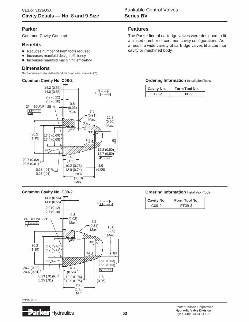
Hydraulics 53
Parker Hannifin CorporationHydraulic Valve DivisionElyria, Ohio 44035 USA
Bankable Control ValvesCatalog 3123/USA
bv.p65, dd, jk
Series BVCavity Details — No. 8 and 9 Size
Common Cavity No. C08-2
Common Cavity No. C09-2
Dimensions*Inch equivalents for millimeter dimensions are shown in (**)
Cavity No. Form Tool No.C08-2 FT08-2
Ordering Information Installation Tools
Cavity No. Form Tool No.C09-2 FT09-2
Ordering Information Installation Tools
ParkerCommon Cavity Concept
Benefits• Reduces number of form tools required
• Increases manifold design efficiency
• Increases manifold machining efficiency
FeaturesThe Parker line of cartridge valves were designed to fita limited number of common cavity configurations. Asa result, a wide variety of cartridge valves fit a commoncavity or machined body.
.05 (.002) A
.05 (.002) B*
14.3 (0.56)14.0 (0.55)
2.9 (0.12)2.5 (0.10)
0.8(0.03)Max.
A
B
.05 (.002) A
3/4 - 16UNF - 2B
45°
30.2(1.19)
17.5 (0.69)17.4 (0.68)
20.7 (0.82)20.6 (0.81)
15° 63
0.13 (.01)R.0.25 (.01)
14.3(0.56)
19.2 (0.76)18.9 (0.75)
1.6(0.06)
28.6(1.13)Min.
30°
6320°
16.0(0.63)Max.
7.9(0.31)Max.
16.0 (0.63)15.9 (0.63)
*
*
*
.03 (.001)
63
14.3 (0.56)14.0 (0.55)
2.9 (0.12)2.5 (0.10)
0.8(0.03)Max.
A
B
.05 (.002) A
.05 (.002) B
.05 (.002) A
3/4 - 16UNF - 2B
45°
30.2(1.19)
17.5 (0.69)17.4 (0.68)
20.7 (0.82)20.6 (0.81)
15° 63
0.13 (.01)R.0.25 (.01)
14.3(0.56)
19.2 (0.76)18.9 (0.74)
1.6(0.06)
28.6(1.13)Min.
30°
6320°
12.8(0.50)Max.
7.9(0.31)Max.
12.8 (0.50)12.7 (0.50)
*
*
*
*
.03 (.001)
63
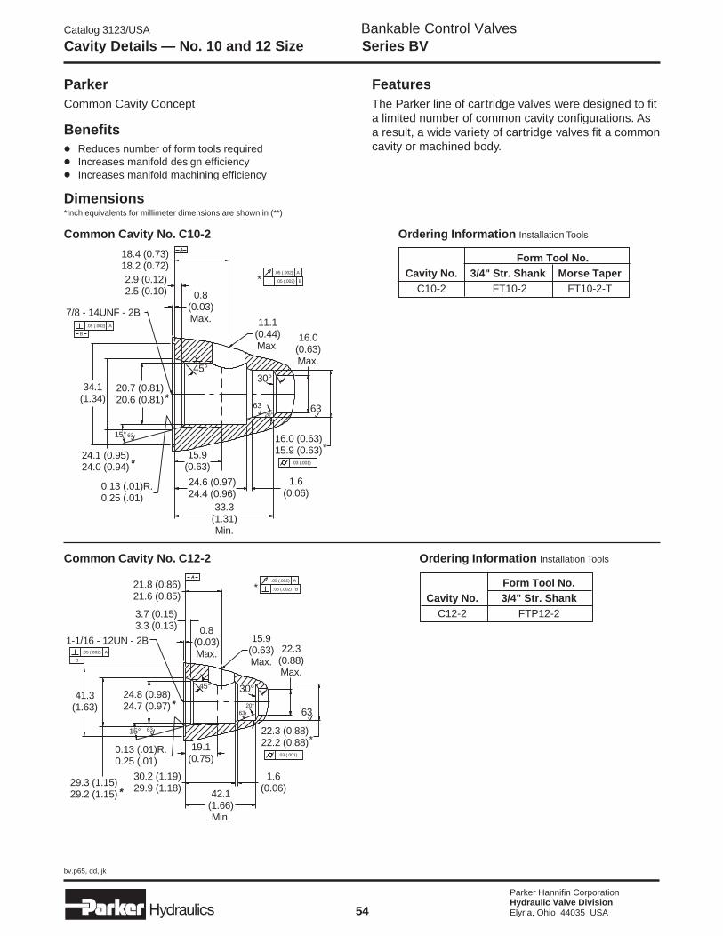
Hydraulics 54
Parker Hannifin CorporationHydraulic Valve DivisionElyria, Ohio 44035 USA
Bankable Control ValvesCatalog 3123/USA
bv.p65, dd, jk
Series BVCavity Details — No. 10 and 12 Size
ParkerCommon Cavity Concept
Benefits• Reduces number of form tools required
• Increases manifold design efficiency
• Increases manifold machining efficiency
FeaturesThe Parker line of cartridge valves were designed to fita limited number of common cavity configurations. Asa result, a wide variety of cartridge valves fit a commoncavity or machined body.
Common Cavity No. C10-2
Common Cavity No. C12-2
Dimensions*Inch equivalents for millimeter dimensions are shown in (**)
Ordering Information Installation Tools
Form Tool No.Cavity No. 3/4" Str. Shank Morse Taper
C10-2 FT10-2 FT10-2-T
Ordering Information Installation Tools
Form Tool No.Cavity No. 3/4" Str. Shank
C12-2 FTP12-2
.05 (.002) A
.05 (.002) B*
18.4 (0.73)18.2 (0.72)2.9 (0.12)2.5 (0.10) 0.8
(0.03)Max.
A
B
.05 (.002) A
7/8 - 14UNF - 2B
34.1(1.34)
20.7 (0.81)20.6 (0.81)*
15° 63
24.1 (0.95)24.0 (0.94)*
0.13 (.01)R.0.25 (.01)
15.9(0.63)
24.6 (0.97)24.4 (0.96)
33.3(1.31)Min.
1.6(0.06)
.03 (.001)
16.0 (0.63)15.9 (0.63)*
16.0(0.63)Max.
63
30°
6320°
45°
11.1(0.44)Max.
.05 (.002) A
.05 (.002) B*21.8 (0.86)21.6 (0.85)
3.7 (0.15)3.3 (0.13) 0.8
(0.03)Max.
A
B
.05 (.002) A
1-1/16 - 12UN - 2B
41.3(1.63)
24.8 (0.98)24.7 (0.97)*
15° 63
29.3 (1.15)29.2 (1.15)*
0.13 (.01)R.0.25 (.01)
19.1(0.75)
30.2 (1.19)29.9 (1.18)
15.9(0.63)Max.
45° 30°
6320°
22.3(0.88)Max.
63
.03 (.001)
22.3 (0.88)22.2 (0.88)*
1.6(0.06)42.1
(1.66)Min.
Hydraulics 55
Parker Hannifin CorporationHydraulic Valve DivisionElyria, Ohio 44035 USA
Bankable Control ValvesCatalog 3123/USA
bv.p65, dd, jk
Series BV
The items described in this document and other documents or descriptions provided by Parker Hannifin Corporation, its subsidiaries and its authorizeddistributors are hereby offered for sale at prices to be established by Parker Hannifin Corporation, its subsidiaries and its authorized distributors. Thisoffer and its acceptance by any customer ("Buyer") shall be governed by all of the following Terms and Conditions. Buyer’s order for any such items,when communicated to Parker Hannifin Corporation, its subsidiary or an authorized distributor ("Seller") verbally or in writing, shall constitute acceptanceof this offer.
paid by Buyer. Unless otherwise agreed, Seller shall have the right to alter,discard or otherwise dispose of any special tooling or other property in itssole discretion at any time.8. Buyer’s Property: Any designs, tools, patterns, materials, drawings,confidential information or equipment furnished by Buyer or any otheritems which become Buyer’s property, may be considered obsolete andmay be destroyed by Seller after two (2) consecutive years have elapsedwithout Buyer placing an order for the items which are manufactured usingsuch property, Seller shall not be responsible for any loss or damage tosuch property while it is in Seller’s possession or control.9. Taxes: Unless otherwise indicated on the face hereof, all prices andcharges are exclusive of excise, sales, use, property, occupational or liketaxes which may be imposed by any taxing authority upon the manufac-ture, sale or delivery of the items sold hereunder. If any such taxes mustbe paid by Seller or if Seller is liable for the collection of such tax, theamount thereof shall be in addition to the amounts for the items sold. Buyeragrees to pay all such taxes or to reimburse Seller therefore upon receiptof its invoice. If Buyer claims exemption from any sales, use or other taximposed by any taxing authority, Buyer shall save Seller harmless fromand against any such tax, together with any interest or penalties thereonwhich may be assessed if the items are held to be taxable.10. Indemnity For Infringement of Intellectual Property Rights: Sellershall have no liability for infringement of any patents, trademarks, copy-rights, trade dress, trade secrets or similar rights except as provided in thisPart 10. Seller will defend and indemnify Buyer against allegations ofinfringement of U.S. Patents, U.S. Trademarks, copyrights, trade dressand trade secrets (hereinafter ‘Intellectual Property Rights’). Seller willdefend at its expense and will pay the cost of any settlement or damagesawarded in an action brought against Buyer based on an allegation thatan item sold pursuant to this contract infringes the Intellectual PropertyRights of a third party. Seller’s obligation to defend and indemnify Buyeris contingent on Buyer notifying Seller within ten (10) days after Buyerbecomes aware of such allegations of infringement, and Seller having solecontrol over the defense of any allegations or actions including allnegotiations for settlement or compromise. If an item sold hereunder issubject to a claim that it infringes the Intellectual Property Rights of a thirdparty, Seller may, at its sole expense and option, procure for Buyer theright to continue using said item, replace or modify said item so as to makeit noninfringing, or offer to accept return of said item and return thepurchase price less a reasonable allowance for depreciation. Notwith-standing the foregoing, Seller shall have no liability for claims of infringe-ment based on information provided by Buyer, or directed to itemsdelivered hereunder for which the designs are specified in whole or partby Buyer, or infringements resulting from the modification, combination oruse in a system of any item sold hereunder. The foregoing provisions ofthis Part 10 shall constitute Seller’s sole and exclusive liability and Buyer’ssole and exclusive remedy for infringement of Intellectual Property Rights.If a claim is based on information provided by Buyer or if the design for anitem delivered hereunder is specified in whole or in part by Buyer, Buyershall defend and indemnify Seller for all costs, expenses or judgmentsresulting from any claim that such item infringes any patent, trademark,copyright, trade dress, trade secret or any similar right.11. Force Majeure: Seller does not assume the risk of and shall not beliable for delay or failure to perform any of Seller’s obligations by reasonof circumstances beyond the reasonable control of Seller (hereinafter‘Events of Force Majeure’). Events of Force Majeure shall include withoutlimitation, accidents, acts of God, strikes or labor disputes, acts, laws,rules or regulations of any government or government agency, fires,floods, delays or failures in delivery of carriers or suppliers, shortages ofmaterials and any other cause beyond Seller’s control.12. Entire Agreement/Governing Law: The terms and conditions setforth herein, together with any amendments, modifications and anydifferent terms or conditions expressly accepted by Seller in writing, shallconstitute the entire Agreement concerning the items sold, and there areno oral or other representations or agreements which pertain thereto. ThisAgreement shall be governed in all respects by the law of the State of Ohio.No actions arising out of the sale of the items sold hereunder or thisAgreement may be brought by either party more than two (2) years afterthe cause of action accrues.
9/91-P
Offer of Sale
1. Terms and Conditions of Sale: All descriptions, quotations, propos-als, offers, acknowledgments, acceptances and sales of Seller’s productsare subject to and shall be governed exclusively by the terms andconditions stated herein. Buyer’s acceptance of any offer to sell is limitedto these terms and conditions. Any terms or conditions in addition to, orinconsistent with those stated herein, proposed by Buyer in any accep-tance of an offer by Seller, are hereby objected to. No such additional,different or inconsistent terms and conditions shall become part of thecontract between Buyer and Seller unless expressly accepted in writingby Seller. Seller’s acceptance of any offer to purchase by Buyer isexpressly conditional upon Buyer’s assent to all the terms and conditionsstated herein, including any terms in addition to, or inconsistent with thosecontained in Buyer’s offer, Acceptance of Seller’s products shall in allevents constitute such assent.2. Payment: Payment shall be made by Buyer net 30 days from the dateof delivery of the items purchased hereunder. Amounts not timely paidshall bear interest at the maximum rate permitted by law for each monthor portion thereof that the Buyer is late in making payment. Any claims byBuyer for omissions or shortages in a shipment shall be waived unlessSeller receives notice thereof within 30 days after Buyer’s receipt of theshipment.3. Delivery: Unless otherwise provided on the face hereof, delivery shallbe made F.O.B. Seller’s plant. Regardless of the method of delivery,however, risk of loss shall pass to Buyer upon Seller’s delivery to a carrier.Any delivery dates shown are approximate only and Seller shall have noliability for any delays in delivery.4. Warranty: Seller warrants that the items sold hereunder shall be freefrom defects in material or workmanship for a period of 18 months fromdate of shipment from Parker Hannifin Corporation. THIS WARRANTYCOMPRISES THE SOLE AND ENTIRE WARRANTY PERTAINING TOITEMS PROVIDED HEREUNDER. SELLER MAKES NO OTHER WAR-RANTY, GUARANTEE, OR REPRESENTATION OF ANY KIND WHAT-SOEVER. ALL OTHER WARRANTIES, INCLUDING BUT NOT LIM-ITED TO, MERCHANTABILITY AND FITNESS FOR PURPOSE,WHETHER EXPRESS, IMPLIED, OR ARISING BY OPERATION OFLAW, TRADE USAGE, OR COURSE OF DEALING ARE HEREBYDISCLAIMED.NOTWITHSTANDING THE FOREGOING, THERE ARE NO WAR-RANTIES WHATSOEVER ON ITEMS BUILT OR ACQUIRED WHOLLYOR PARTIALLY, TO BUYER’S DESIGNS OR SPECIFICATIONS.5. Limitation Of Remedy: SELLER’S LIABILITY ARISING FROM OR INANY WAY CONNECTED WITH THE ITEMS SOLD OR THIS CON-TRACT SHALL BE LIMITED EXCLUSIVELY TO REPAIR OR RE-PLACEMENT OF THE ITEMS SOLD OR REFUND OF THE PURCHASEPRICE PAID BY BUYER, AT SELLER’S SOLE OPTION. IN NO EVENTSHALL SELLER BE LIABLE FOR ANY INCIDENTAL, CONSEQUEN-TIAL OR SPECIAL DAMAGES OF ANY KIND OR NATURE WHATSO-EVER, INCLUDING BUT NOT LIMITED TO LOST PROFITS ARISINGFROM OR IN ANY WAY CONNECTED WITH THIS AGREEMENT ORITEMS SOLD HEREUNDER, WHETHER ALLEGED TO ARISE FROMBREACH OF CONTRACT, EXPRESS OR IMPLIED WARRANTY, ORIN TORT, INCLUDING WITHOUT LIMITATION, NEGLIGENCE, FAIL-URE TO WARN OR STRICT LIABILITY.6. Changes, Reschedules and Cancellations: Buyer may request tomodify the designs or specifications for the items sold hereunder as wellas the quantities and delivery dates thereof, or may request to cancel allor part of this order, however, no such requested modification or cancel-lation shall become part of the contract between Buyer and Seller unlessaccepted by Seller in a written amendment to this Agreement. Acceptanceof any such requested modification or cancellation shall be at Seller’sdiscretion, and shall be upon such terms and conditions as Seller mayrequire.7. Special Tooling: A tooling charge may be imposed for any specialtooling, including without limitation, dies, fixtures, molds and patterns,acquired to manufacture items sold pursuant to this contract. Such specialtooling shall be and remain Seller’s property notwithstanding payment ofany charges by Buyer. In no event will Buyer acquire any interest inapparatus belonging to Seller which is utilized in the manufacture of theitems sold hereunder, even if such apparatus has been specially con-verted or adapted for such manufacture and notwithstanding any charges

Hydraulics 56
Parker Hannifin CorporationHydraulic Valve DivisionElyria, Ohio 44035 USA
Bankable Control ValvesCatalog 3123/USA
bv.p65, dd, jk
Series BVParker Hydraulics International Sales Offices
GermanyParker Hannifin GmbHGutenbergstrasse 38-40D-41564 Kaarst, GermanyTel: 49-2131-513-0Fax: 49-2131-513-230
GreeceParker Hannifin CorporationRepresentation Office Athens8-10 Manis StreetGR Piraeus 185-39, GreeceTel: 30-1-4184415Fax: 30-1-4184415
HungaryParker Hannifin CorporationBudapest Representation OfficeBudapesti Kepviseleti IrodaH-1148 Budapest, HungaryVezer ut 156-158Tel: 36-1-252 8137Fax: 36-1-252 8129
ItalyParker Hannifin SpAVia Privata Archimede 1I-20094 Corsico,Milano, ItalyTel: 39-02-451921Fax: 39-02-4479340
The NetherlandsParker Hannifin B.V.Edisonstraat 1NL-7570 AT Oldenzaal, HollandTel: 31-541-585000Fax: 31-541-585459
NorwayParker Hannifin A/SBerghaganP.O. Box 8N-1405 Langhus, NorwayTel: 47-64-86 77 60Fax: 47-64-86 68 88
PolandParker Hannifin CorporationParowcowa 8 B02-445 Warsaw, PolandTel: 48-22-8634942Fax: 48-22-8634944
Parker Europe
AustriaParker Hannifin NMFHandelskai 52A-1200 Vienna, AustriaTel: 43-1-33236050Fax: 43-1-332360577
BelgiumParker Hannifin S.A.N.V.Av. Marcel Thirylaan 200DB-1200 Brussels, BelgiumTel: 32-2-7 62 18 00Fax: 32-2-7 62 33 30
Czech RepublicParker HannifinNovodvorska 1010/14CZ-10222 Praha 4, Czech RepublicTel: 42-02-6134 1704Fax: 42-02-6134 1703
DenmarkParker Hannifin DK A/SIndustrigrenen 11DK-2635 Ishoj, DenmarkTel: 45-4356 0400Fax: 45-4273 3107
EnglandParker Hannifin plc6 Greycaine RoadGB-Watford, Herts WD2 4QAEnglandTel: 44-1923-492000Fax: 44-1923-256059
FinlandParker Hannifin OyYlastontie 16FIN-01510 Vantaa, FinlandTel: 358-9-476 731Fax: 358-9-4767 3200
FranceParker Hannifin S.A.Z.A.E. La ForetF-74138 Contamine-sur-Arve, FranceTel: 33-4-5025 8025Fax: 33-4-5003 6737
Parker Hannifin CorporationHydraulic Valve Division520 Ternes AvenueElyria, OH 44035Tel: 440-366-5100Fax: 440-366-5253
Great Lakes Region6035 Parkland BoulevardCleveland, OH 44124Tel: 216-896-3000Fax: 216-896-4000
Gulf Region1701 N. Collins Blvd. #139Richardson, TX 75080Tel: 972-238-5020Fax: 972-238-5029
Michigan Region651 Robbins DriveTroy, MI 48007Tel: 248-589-3500Fax: 248-589-4769
Northwest Region1200 Westlake Avenue, N, #815Seattle, WA 98109Tel: 206-285-7559Fax: 206-285-7432
Southern Region1990 Lakeside Parkway, Suite185Tucker, GA 30084Tel: 770-270-5055Fax: 770-270-5436
Chicago Region500 South Wolf RoadDes Plaines, IL 60016Tel: 847-294-2628Fax: 847-294-2630
Pacific Region16655 Noyes AvenueIrvine, CA 92714Tel: 714-660-7033Fax: 714-852-9577
Parker VOACMobile Sales Office409 W. Algonquin RoadMt. Prospect, Ill 60056Tel: 847-437-8200Fax: 847-437-8272
Canada530 Kipling AvenueToronto, Ontario M8Z 5E6Tel: 416-255-7371Fax: 416-255-2107
MexicoCalle 9, No. 6 Alce Blanco053370 NaucalpanEdo de MexicoTel: 525-576-2411Fax: 525-358-1823
USA
8/1/98
CAN
MEX
A
B
DK
GB
NL
F
D
I
CZ
FINN
PL
H
GR

Hydraulics 57
Parker Hannifin CorporationHydraulic Valve DivisionElyria, Ohio 44035 USA
Bankable Control ValvesCatalog 3123/USA
bv.p65, dd, jk
Series BVParker Hydraulics International Sales Offices
Hong KongParker Hannifin Hong Kong Ltd.8/F, Kin Yip Plaza,9 Cheung Yee StreetCleung Sha Wan,Kowloon, Hong KongTel: 852-2428 8008Fax: 852-2480 4256
IndiaParker Hannifin India701, Gateway PlazaHiranandani Gardens, PowaiMumbai, 400076, Bombay, IndiaTel: 91-22-5771671Fax: 91-22-6290009
JapanParker Hannifin Japan, Ltd.626 Totsuka-cho, Totsuka-kuYokohama-shi 244, JapanTel: 81-45-861-3811Fax: 81-45-864-5305
KoreaParker Hannifin Asia Pacific Co. Ltd.902 Dae Heung Bldg.648-23 Yeoksam-dongKangnam-ku, Seoul, Korea 135-080Tel: 82-2-561 0414Fax: 82-2-556 8187
New ZealandParker Hannifin (N.Z.) Ltd.103 Harris Road, East TamakiPrivate Bag 14906, PanmureAuckland, New ZealandTel: 64-9-273 8944Fax: 64-9-273 8943
PhilippinesParker Hannifin Representative OfficeUnit 205, Richville Corporate Centre1314, Commerce AvenueMadrigal Business Park, Ayala AlabanMuntiniupa City, PhilippinesTel: 63-2 809 5903Fax: 63-2 809 5864
SingaporeParker Hannifin Singapore Pte. Ltd.No. 11 4th Chin Bee RoadJurong Town, Singapore 619702Republic of SingaporeTel: 65-261 5233Fax: 65-265 5125
8/1/98
PortugalParker Hannifin CorporationRua Oscar de Silva, 1559-4 Dt. TrasLeca de PalmeiraP-4450 Matosinhos, PortugalTel: 35-1-2-9961526Fax: 35-1-2-9961527
RussiaParker Hannifin CorporationKomsomolsky Prospect 42,Office 47119827 GSP Moscow G-48, RussiaTel: 7-095-234 0054Fax: 7-095-234 0054
SpainParker Hannifin Espana S.A.Industrial Las Monjas ParqueCalle De Las Estaciones 828850 Torrejon de ArdozMadrid, SpainTel: 34-91-6757300Fax: 34-91-6757711
SwedenParker Hannifin Sweden ABFagerstagatan 51Box 8314S-163 08 Spanga, SwedenTel: 46-8-760 29 60Fax: 46-8-761 81 70
Asia Pacific Group
AustraliaParker Hannifin Australia9 Carrington RoadCastle Hill, NSW 2154, AustraliaTel: 61-2-9634-7777Fax: 61-2-9842-5111
ChinaParker Hannifin Hong Kong Ltd.Beijing OfficeSuite B9-B11, 21st fl., Hanwei Bldg.No. 7 Guanghua Road, Chaoyang DistrictBeijing, 100004, People Republic of ChinaTel: 86-10-6561-0520Fax: 86-10-6561-0526
Parker Hannifin Hong Kong Ltd.Shanghai OfficeRoom 1101, Peregrine Plaza1325 Huai Hai Road (M)Shanghai, 200031, People Republic of ChinaTel: 86-21-6445 9339Fax: 86-21-6445 9717
TaiwanParker Hannifin Taiwan Co., Ltd.87-1, No. 102, Sung Lung RoadTaipei, Taiwan, R.O.C.Tel: 886-2 8787 3780Fax: 886-2 8787 3782
ThailandParker Hannifin Thailand Co., Ltd.Muang Thai Phatra Office Tower II252/96 18th floor, Unit ERachadaphisek RoadHuaykwang, Bangkok 1j0320Tel: 662-693 3304Fax: 662-693 3307
Latin American Group
Pan American DivisionParker Hannifin Corporation7400 NW Corporate Center.Dr.STE.AMiami, Florida 33126Tel: 1-305 470 8800Fax: 1-305 470 8808
ArgentinaParker Hannifin Argentina S.A.I.C.Avda. Pte. Arturo U Illia 2064Villa Maipu, 1650 San MartinProv. Buenos Aires, ArgentinaTel: 54-1-752 4129Fax: 54-1-752 3704
BrazilParker Hannifin Ind. e Com. Ltda.Av. Lucas Nogueira Garcez 218112300-000 Jacarei, SP, BrazilTel: 55-12-354 5100Fax: 55-12-354 5262
VenezuelaParker Hannifin deVenezuela S.A.Edificio Draza PB-1 y PB-2Boleita NorteCaracas, VenezuelaTel: 58-2-238 5422Fax: 58-2-239 2272
Africa
South AfricaParker Hannifin Africa Pty. Ltd.Parker Place10 Berne AvenueAeroport, Kempton ParkKempton Park 1620, South AfricaTel: 27-11-3927280Fax: 27-11-3927213
RUS
V
BRNZ
RP
J
IND
E
T
S
AUS
SGP
CHN
USA
RA
HKP RC
ROK
ZA

Parker’s CharterTo be a leading worldwide manufacturer of compo-nents and systems for the builders and users of durablegoods. More specifically, we will design, market andmanufacture products controlling motion, flow andpressure. We will achieve profitable growth throughpremier customer service.
Product InformationNorth American customers seeking product infor-mation, the location of a nearby distributor, or repairservices will receive prompt attention by calling theParker Product Information Center at our toll-free num-ber: 1-800-C-PARKER (1-800-272-7537). In the UK, asimilar service is available by calling 0500-103-203.
The Aerospace Group isa leader in the development,design, manufacture and ser-vicing of control systems andcomponents for aerospace andrelated high-technology mar-kets, while achieving growththrough premier customer ser-vice.
The Fluid ConnectorsGroup designs, manufacturesand markets rigid and flexibleconnectors, and associatedproducts used in pneumaticand fluid systems.
The Hydraulics Groupdesigns, produces and mar-kets a full spectrum of hydrau-lic components and systems tobuilders and users of indus-trial and mobile machineryand equipment.
The Automation Groupis a leading supplier of pneu-matic and electromechanicalcomponents and systems toautomation customers world-wide.
The Climate & IndustrialControls Group designs,manufactures and marketssystem-control and fluid-han-dling components and systemsto refrigeration, air-condition-ing and industrial customersworldwide.
The Seal Group designs,manufactures and distributesindustrial and commercialsealing devices and relatedproducts by providingsuperior quality and totalcustomer satisfaction.
The Filtration Groupdesigns, manufactures andmarkets quality filtration andclarification products, provid-ing customers with the bestvalue, quality, technical sup-port, and global availability.
The InstrumentationGroup is a global leader inthe design, manufacture anddistribution of high-qualitycritical flow components forworldwide process instrumen-tation, ultra-high-purity, medi-cal and analytical applications.
About Parker Hannifin CorporationParker Hannifin is a leading global motion-controlcompany dedicated to delivering premier customerservice. A Fortune 500 corporation listed on the NewYork Stock Exchange (PH), our components and sys-tems comprise over 1,400 product lines that controlmotion in some 1,000 industrial and aerospace mar-kets. Parker is the only manufacturer to offer itscustomers a choice of hydraulic, pneumatic, andelectromechanical motion-control solutions. Our Com-pany has the largest distribution network in its field,with over 7,500 distributors serving more than 350,000customers worldwide.
Parker Hannifin Corporation6035 Parkland Blvd.Cleveland, Ohio 44124-4141Telephone: (216) 896-3000Fax: (216) 896-4000Web site: www.parker.com
Parker Hannifin Corporation

Catalog 3123/USA,7.5M, 11/98, AP
Parker Hannifin CorporationHydraulic Valve Division520 Ternes AvenueElyria, Ohio 44035 USATel: (440) 366-5200Fax: (440) 366-5253Web Site: http://www.parker.com/hydraulicvalve
Hydraulics

Parker Hannifin CorporationHydraulic Valve DivisionElyria, Ohio, USA
1
Bulletin HY14-2104/US
Series MV4Multi-Pak DirectionalControl Valves
Effective: February 1, 2004Supersedes: Cat. No. PMF 1003 dated 10/99
Specifications
DescriptionThe Parker Series MV4 Multi-Pak, solenoid-operated valvesoffer a modular banking design concept which eliminates costlyfittings and potential leak points that simplify both factory andfield installations.
In addition to banking directional control valves, the mainsystem relief valve may also be banked.
Attachment options including crossover reliefs, single anddouble, pilot-operated checks as well as anti-cavitation checks,can be stacked on the cylinder ports.
All Parker Multi-Pak valves utilize the proven wet plunger designfor trouble-free performance even in continuous-duty applica-tions.
Features• Solenoid-operated valves incorporate manual overrides
for virtually fail-safe performance
• Spool configurations allow for open-center series orclosed-center parallel circuit stacks
• Solenoid coils are weather-resistant and rated forcontinuous duty at nominal voltage. They provide forlow current consumption to minimize energy usage.
• Bankable inlet relief
• Inlet dump valve for use with parallel circuits
• Mid inlet/outlet section
• DC solenoid coils
• Various solenoid coil terminations
• Palm button manual overrides
• Proportional flow inlets (main & mid)
Flow: 12 GPM (45 L/M)*. For higher flow applications, consult factory.
Operating Pressure: Parallel Bank: 3000 PSI (207 Bar). Series Bank: 2500 PSI (172 Bar).
Operating Fluid: Standard petroleum-based.
Leakage C-T at 3000 PSI (207 Bar): 14.9 in3/min. (244 cc/min.) at 100°F (38°C), 150 SSU (32 cSt).
Filtration Requirement: Recommend 25 micron (nominal). Class 18/15 according to ISO 4406, or cleaner.

Parker Hannifin CorporationHydraulic Valve DivisionElyria, Ohio, USA
2
PERFORMANCE
MATERIALS
NOTE: SAE 10 oil at 100°F (38°C), Viscosity 150 SSU (32 cSt)
MOTOR SPOOLCENTERMV4 17-A Shown

Parker Hannifin CorporationHydraulic Valve DivisionElyria, Ohio, USA
3
DIMENSIONS
DIMENSIONS ARE IN INCHES (MILLIMETERS) AND ARE FOR REFERENCE ONLY.

Parker Hannifin CorporationHydraulic Valve DivisionElyria, Ohio, USA
4
OPTIONS

Parker Hannifin CorporationHydraulic Valve DivisionElyria, Ohio, USA
5
ORDER CODE
HOW TO ORDER: Parker Mini-Pak Valves are coded by the assembled stack configuration (Left to Right) in asequential order from inlet to outlet. Please refer to the ordering tables, to select a circuit type, inlet options,spool configuration, spool options, circuit conversion options as they apply to your application.

Parker Hannifin CorporationHydraulic Valve DivisionElyria, Ohio, USA
6
The items described in this document and other documents or descriptions provided by Parker Hannifin Corporation, its subsidiaries and its authorizeddistributors are hereby offered for sale at prices to be established by Parker Hannifin Corporation, its subsidiaries and its authorized distributors. Thisoffer and its acceptance by any customer (“Buyer”) shall be governed by all of the following Terms and Conditions. Buyer’s order for any such items,when communicated to Parker Hannifin Corporation, its subsidiary or an authorized distributor (“Seller”) verbally or in writing, shall constitute acceptanceof this offer.
1. Terms and Conditions of Sale: All descriptions, quotations, proposals,offers, acknowledgments, acceptances and sales of Seller’s products aresubject to and shall be governed exclusively by the terms and conditionsstated herein. Buyer’s acceptance of any offer to sell is limited to theseterms and conditions. Any terms or conditions in addition to, or inconsistentwith those stated herein, proposed by Buyer in any acceptance of an offerby Seller, are hereby objected to. No such additional, different or inconsistentterms and conditions shall become part of the contract between Buyer andSeller unless expressly accepted in writing by Seller. Seller’s acceptanceof any offer to purchase by Buyer is expressly conditional upon Buyer’sassent to all the terms and conditions stated herein, including any termsin addition to, or inconsistent with those contained in Buyer’s offer,Acceptance of Seller’s products shall in all events constitute such assent.2. Payment: Payment shall be made by Buyer net 30 days from the dateof delivery of the items purchased hereunder. Amounts not timely paidshall bear interest at the maximum rate permitted by law for each monthor portion thereof that the Buyer is late in making payment. Any claims byBuyer for omissions or shortages in a shipment shall be waived unlessSeller receives notice thereof within 30 days after Buyer’s receipt of theshipment.3. Delivery: Unless otherwise provided on the face hereof, delivery shallbe made F.O.B. Seller’s plant. Regardless of the method of delivery,however, risk of loss shall pass to Buyer upon Seller’s delivery to a carrier.Any delivery dates shown are approximate only and Seller shall have noliability for any delays in delivery.4. Warranty: Seller warrants that the items sold hereunder shall be freefrom defects in material or workmanship for a period of 18 months fromdate of shipment from Parker Hannifin Corporation. THIS WARRANTYCOMPRISES THE SOLE AND ENTIRE WARRANTY PERTAINING TOITEMS PROVIDED HEREUNDER. SELLER MAKES NO OTHERWARRANTY, GUARANTEE, OR REPRESENTATION OF ANY KINDWHATSOEVER. ALL OTHER WARRANTIES, INCLUDING BUT NOTLIMITED TO, MERCHANTABILITY AND FITNESS FOR PURPOSE,WHETHER EXPRESS, IMPLIED, OR ARISING BY OPERATION OFLAW, TRADE USAGE, OR COURSE OF DEALING ARE HEREBYDISCLAIMED. NOTWITHSTANDING THE FOREGOING, THERE ARENO WARRANTIES WHATSOEVER ON ITEMS BUILT OR ACQUIREDWHOLLY OR PARTIALLY, TO BUYER’S DESIGNS ORSPECIFICATIONS.5. Limitation Of Remedy: SELLER’S LIABILITY ARISING FROM OR INANY WAY CONNECTED WITH THE ITEMS SOLD OR THIS CONTRACTSHALL BE LIMITED EXCLUSIVELY TO REPAIR OR REPLACEMENTOF THE ITEMS SOLD OR REFUND OF THE PURCHASE PRICE PAIDBY BUYER, AT SELLER’S SOLE OPTION. IN NO EVENT SHALLSELLER BE LIABLE FOR ANY INCIDENTAL, CONSEQUENTIAL ORSPECIAL DAMAGES OF ANY KIND OR NATURE WHATSOEVER,INCLUDING BUT NOT LIMITED TO LOST PROFITS ARISING FROMOR IN ANY WAY CONNECTED WITH THIS AGREEMENT OR ITEMSSOLD HEREUNDER, WHETHER ALLEGED TO ARISE FROM BREACHOF CONTRACT, EXPRESS OR IMPLIED WARRANTY, OR IN TORT,INCLUDING WITHOUT LIMITATION, NEGLIGENCE, FAILURE TOWARN OR STRICT LIABILITY.6. Changes, Reschedules and Cancellations: Buyer may request tomodify the designs or specifications for the items sold hereunder as wellas the quantities and delivery dates thereof, or may request to cancel allor part of this order, however, no such requested modification or cancellationshall become part of the contract between Buyer and Seller unlessaccepted by Seller in a written amendment to this Agreement. Acceptanceof any such requested modification or cancellation shall be at Seller’sdiscretion, and shall be upon such terms and conditions as Seller mayrequire.7. Special Tooling: A tooling charge may be imposed for any specialtooling, including without limitation, dies, fixtures, molds and patterns,acquired to manufacture items sold pursuant to this contract. Such specialtooling shall be and remain Seller’s property notwithstanding payment ofany charges by Buyer. In no event will Buyer acquire any interest inapparatus belonging to Seller which is utilized in the manufacture of theitems sold hereunder, even if such apparatus has been specially convertedor adapted for such manufacture and notwithstanding any charges paid
by Buyer. Unless otherwise agreed, Seller shall have the right to alter,discard or otherwise dispose of any special tooling or other property in itssole discretion at any time.8. Buyer’s Property: Any designs, tools, patterns, materials, drawings,confidential information or equipment furnished by Buyer or any otheritems which become Buyer’s property, may be considered obsolete andmay be destroyed by Seller after two (2) consecutive years have elapsedwithout Buyer placing an order for the items which are manufactured usingsuch property, Seller shall not be responsible for any loss or damage tosuch property while it is in Seller’s possession or control.9. Taxes: Unless otherwise indicated on the face hereof, all prices andcharges are exclusive of excise, sales, use, property, occupational or liketaxes which may be imposed by any taxing authority upon the manufacture,sale or delivery of the items sold hereunder. If any such taxes must be paidby Seller or if Seller is liable for the collection of such tax, the amountthereof shall be in addition to the amounts for the items sold. Buyer agreesto pay all such taxes or to reimburse Seller therefore upon receipt of itsinvoice. If Buyer claims exemption from any sales, use or other taximposed by any taxing authority, Buyer shall save Seller harmless fromand against any such tax, together with any interest or penalties thereonwhich may be assessed if the items are held to be taxable.10. Indemnity For Infringement of Intellectual Property Rights: Sellershall have no liability for infringement of any patents, trademarks, copyrights,trade dress, trade secrets or similar rights except as provided in this Part10. Seller will defend and indemnify Buyer against allegations ofinfringement of U.S. Patents, U.S. Trademarks, copyrights, trade dressand trade secrets (hereinafter ‘Intellectual Property Rights’). Seller willdefend at its expense and will pay the cost of any settlement or damagesawarded in an action brought against Buyer based on an allegation thatan item sold pursuant to this contract infringes the Intellectual PropertyRights of a third party. Seller’s obligation to defend and indemnify Buyeris contingent on Buyer notifying Seller within ten (10) days after Buyerbecomes aware of such allegations of infringement, and Seller having solecontrol over the defense of any allegations or actions including allnegotiations for settlement or compromise. If an item sold hereunder issubject to a claim that it infringes the Intellectual Property Rights of a thirdparty, Seller may, at its sole expense and option, procure for Buyer theright to continue using said item, replace or modify said item so as to makeit noninfringing, or offer to accept return of said item and return thepurchase price less a reasonable allowance for depreciation.Notwithstanding the foregoing, Seller shall have no liability for claims ofinfringement based on information provided by Buyer, or directed to itemsdelivered hereunder for which the designs are specified in whole or partby Buyer, or infringements resulting from the modification, combination oruse in a system of any item sold hereunder. The foregoing provisions ofthis Part 10 shall constitute Seller’s sole and exclusive liability and Buyer’ssole and exclusive remedy for infringement of Intellectual Property Rights.If a claim is based on information provided by Buyer or if the design for anitem delivered hereunder is specified in whole or in part by Buyer, Buyershall defend and indemnify Seller for all costs, expenses or judgmentsresulting from any claim that such item infringes any patent, trademark,copyright, trade dress, trade secret or any similar right.11. Force Majeure: Seller does not assume the risk of and shall not beliable for delay or failure to perform any of Seller’s obligations by reasonof circumstances beyond the reasonable control of Seller (hereinafter‘Events of Force Majeure’). Events of Force Majeure shall include withoutlimitation, accidents, acts of God, strikes or labor disputes, acts, laws,rules or regulations of any government or government agency, fires,floods, delays or failures in delivery of carriers or suppliers, shortages ofmaterials and any other cause beyond Seller’s control.12. Entire Agreement/Governing Law: The terms and conditions setforth herein, together with any amendments, modifications and anydifferent terms or conditions expressly accepted by Seller in writing, shallconstitute the entire Agreement concerning the items sold, and there areno oral or other representations or agreements which pertain thereto. ThisAgreement shall be governed in all respects by the law of the State of Ohio.No actions arising out of the sale of the items sold hereunder or thisAgreement may be brought by either party more than two (2) years afterthe cause of action accrues.
9/91-P
Offer of Sale

Parker Hannifin CorporationHydraulic Valve DivisionElyria, Ohio, USA
7
Notes

Bulletin HY14-2104/US,3C, 2/04, PHD
Parker Hannifin CorporationHydraulic Valve Division520 Ternes AvenueElyria, Ohio, USA 44035Tel: (440) 366-5200Fax: (440) 366-5253www.parker.com/hydraulicvalve
Copyright 2004, Parker Hannifin Corporation, All Rights Reserved
FAILURE OR IMPROPER SELECTION OR IMPROPER USE OF THE PRODUCTS AND/OR SYSTEMS DESCRIBED HEREIN OR RELATED ITEMS CAN CAUSE DEATH, PERSONAL INJURY AND PROPERTYDAMAGE.
This document and other information from Parker Hannifin Corporation, its subsidiaries and authorized distributors provide product and/or system options for further investigation by users having technical expertise. It isimportant that you analyze all aspects of your application and review the information concerning the product or system in the current product catalog. Due to the variety of operating conditions and applications for theseproducts or systems, the user, through its own analysis and testing, is solely responsible for making the final selection of the products and systems and assuring that all performance, safety and warning requirements ofthe application are met.
The products described herein, including without limitation, product features, specifications, designs, availability and pricing, are subject to change by Parker Hannifin Corporation and its subsidiaries at any time withoutnotice.
WARNING
The items described in this document are hereby offered for sale by Parker Hannifin Corporation, its subsidiaries or its authorized distributors. This offer and its acceptance are governed by the provisions stated in the "Offerof Sale".
Offer of Sale

Parker Hannifin CorporationHydraulic Valve DivisionElyria, Ohio, USA
1
Bulletin HY14-2105/US
Series MV5Mini-Pak DirectionalControl Valves
Effective: February 1, 2004Supersedes: Cat. No. PMF 1004 dated 10/99
Specifications
DescriptionThe Parker Series MV4 Mini-Pak, solenoid-operated valvesprovide multiple-function directional control. The modularbanking design concept eliminates costly fittings and potentialleak points. Parker Mini-Pak valves are easy to install in boththe factory and in the field.
Solenoid actuator construction utilizes the proven wet plungerdesign. Series, parallel and series-parallel valve circuitry offersapplication flexibility and energy savings potential.
Features• Superior versatility in many combinations of different
working sections
• Unique series/parallel banking
• Full manual overrides
• Optional high flow inlets (low ∆P)
• Solenoid coils are weather-resistant and providecontinuous duty at nominal rated voltage
• Proportional flow inlet
• Both open and closed center configurations
• Power beyond feature
Flow: 6 GPM (23 L/M).
Operating Pressure: 3000 PSI (207 Bar) maximum.
Operating Fluid: Standard petroleum-based.
Leakage C-T at 3000 PSI (207 Bar): 10.8 in3/min. (177 cc/min.) at 100°F (38°C), 150 SSU (32 cSt).
Filtration Requirement: Recommend 25 micron (nominal). Class 18/15 according to ISO 4406, or cleaner.

Parker Hannifin CorporationHydraulic Valve DivisionElyria, Ohio, USA
2
PERFORMANCE
MATERIALS
NOTE: SAE 10 oil at 100°F (38°C), Viscosity 150 SSU (32 cSt)

Parker Hannifin CorporationHydraulic Valve DivisionElyria, Ohio, USA
3
DIMENSIONS
DIMENSIONS ARE IN INCHES (MILLIMETERS) AND ARE FOR REFERENCE ONLY.

Parker Hannifin CorporationHydraulic Valve DivisionElyria, Ohio, USA
4
OPTIONS

Parker Hannifin CorporationHydraulic Valve DivisionElyria, Ohio, USA
5
ORDER CODE
HOW TO ORDER: Parker Mini-Pak Valves are coded by the assembled stack configuration (Left to Right) in a sequential order from inlet to outlet. Please refer to theordering tables, to select a circuit type, inlet options, spool configuration, spool options, circuit conversion options as they apply to your application.

Parker Hannifin CorporationHydraulic Valve DivisionElyria, Ohio, USA
6
The items described in this document and other documents or descriptions provided by Parker Hannifin Corporation, its subsidiaries and its authorizeddistributors are hereby offered for sale at prices to be established by Parker Hannifin Corporation, its subsidiaries and its authorized distributors. Thisoffer and its acceptance by any customer (“Buyer”) shall be governed by all of the following Terms and Conditions. Buyer’s order for any such items,when communicated to Parker Hannifin Corporation, its subsidiary or an authorized distributor (“Seller”) verbally or in writing, shall constitute acceptanceof this offer.
1. Terms and Conditions of Sale: All descriptions, quotations, proposals,offers, acknowledgments, acceptances and sales of Seller’s products aresubject to and shall be governed exclusively by the terms and conditionsstated herein. Buyer’s acceptance of any offer to sell is limited to theseterms and conditions. Any terms or conditions in addition to, or inconsistentwith those stated herein, proposed by Buyer in any acceptance of an offerby Seller, are hereby objected to. No such additional, different or inconsistentterms and conditions shall become part of the contract between Buyer andSeller unless expressly accepted in writing by Seller. Seller’s acceptanceof any offer to purchase by Buyer is expressly conditional upon Buyer’sassent to all the terms and conditions stated herein, including any termsin addition to, or inconsistent with those contained in Buyer’s offer,Acceptance of Seller’s products shall in all events constitute such assent.2. Payment: Payment shall be made by Buyer net 30 days from the dateof delivery of the items purchased hereunder. Amounts not timely paidshall bear interest at the maximum rate permitted by law for each monthor portion thereof that the Buyer is late in making payment. Any claims byBuyer for omissions or shortages in a shipment shall be waived unlessSeller receives notice thereof within 30 days after Buyer’s receipt of theshipment.3. Delivery: Unless otherwise provided on the face hereof, delivery shallbe made F.O.B. Seller’s plant. Regardless of the method of delivery,however, risk of loss shall pass to Buyer upon Seller’s delivery to a carrier.Any delivery dates shown are approximate only and Seller shall have noliability for any delays in delivery.4. Warranty: Seller warrants that the items sold hereunder shall be freefrom defects in material or workmanship for a period of 18 months fromdate of shipment from Parker Hannifin Corporation. THIS WARRANTYCOMPRISES THE SOLE AND ENTIRE WARRANTY PERTAINING TOITEMS PROVIDED HEREUNDER. SELLER MAKES NO OTHERWARRANTY, GUARANTEE, OR REPRESENTATION OF ANY KINDWHATSOEVER. ALL OTHER WARRANTIES, INCLUDING BUT NOTLIMITED TO, MERCHANTABILITY AND FITNESS FOR PURPOSE,WHETHER EXPRESS, IMPLIED, OR ARISING BY OPERATION OFLAW, TRADE USAGE, OR COURSE OF DEALING ARE HEREBYDISCLAIMED. NOTWITHSTANDING THE FOREGOING, THERE ARENO WARRANTIES WHATSOEVER ON ITEMS BUILT OR ACQUIREDWHOLLY OR PARTIALLY, TO BUYER’S DESIGNS ORSPECIFICATIONS.5. Limitation Of Remedy: SELLER’S LIABILITY ARISING FROM OR INANY WAY CONNECTED WITH THE ITEMS SOLD OR THIS CONTRACTSHALL BE LIMITED EXCLUSIVELY TO REPAIR OR REPLACEMENTOF THE ITEMS SOLD OR REFUND OF THE PURCHASE PRICE PAIDBY BUYER, AT SELLER’S SOLE OPTION. IN NO EVENT SHALLSELLER BE LIABLE FOR ANY INCIDENTAL, CONSEQUENTIAL ORSPECIAL DAMAGES OF ANY KIND OR NATURE WHATSOEVER,INCLUDING BUT NOT LIMITED TO LOST PROFITS ARISING FROMOR IN ANY WAY CONNECTED WITH THIS AGREEMENT OR ITEMSSOLD HEREUNDER, WHETHER ALLEGED TO ARISE FROM BREACHOF CONTRACT, EXPRESS OR IMPLIED WARRANTY, OR IN TORT,INCLUDING WITHOUT LIMITATION, NEGLIGENCE, FAILURE TOWARN OR STRICT LIABILITY.6. Changes, Reschedules and Cancellations: Buyer may request tomodify the designs or specifications for the items sold hereunder as wellas the quantities and delivery dates thereof, or may request to cancel allor part of this order, however, no such requested modification or cancellationshall become part of the contract between Buyer and Seller unlessaccepted by Seller in a written amendment to this Agreement. Acceptanceof any such requested modification or cancellation shall be at Seller’sdiscretion, and shall be upon such terms and conditions as Seller mayrequire.7. Special Tooling: A tooling charge may be imposed for any specialtooling, including without limitation, dies, fixtures, molds and patterns,acquired to manufacture items sold pursuant to this contract. Such specialtooling shall be and remain Seller’s property notwithstanding payment ofany charges by Buyer. In no event will Buyer acquire any interest inapparatus belonging to Seller which is utilized in the manufacture of theitems sold hereunder, even if such apparatus has been specially convertedor adapted for such manufacture and notwithstanding any charges paid
by Buyer. Unless otherwise agreed, Seller shall have the right to alter,discard or otherwise dispose of any special tooling or other property in itssole discretion at any time.8. Buyer’s Property: Any designs, tools, patterns, materials, drawings,confidential information or equipment furnished by Buyer or any otheritems which become Buyer’s property, may be considered obsolete andmay be destroyed by Seller after two (2) consecutive years have elapsedwithout Buyer placing an order for the items which are manufactured usingsuch property, Seller shall not be responsible for any loss or damage tosuch property while it is in Seller’s possession or control.9. Taxes: Unless otherwise indicated on the face hereof, all prices andcharges are exclusive of excise, sales, use, property, occupational or liketaxes which may be imposed by any taxing authority upon the manufacture,sale or delivery of the items sold hereunder. If any such taxes must be paidby Seller or if Seller is liable for the collection of such tax, the amountthereof shall be in addition to the amounts for the items sold. Buyer agreesto pay all such taxes or to reimburse Seller therefore upon receipt of itsinvoice. If Buyer claims exemption from any sales, use or other taximposed by any taxing authority, Buyer shall save Seller harmless fromand against any such tax, together with any interest or penalties thereonwhich may be assessed if the items are held to be taxable.10. Indemnity For Infringement of Intellectual Property Rights: Sellershall have no liability for infringement of any patents, trademarks, copyrights,trade dress, trade secrets or similar rights except as provided in this Part10. Seller will defend and indemnify Buyer against allegations ofinfringement of U.S. Patents, U.S. Trademarks, copyrights, trade dressand trade secrets (hereinafter ‘Intellectual Property Rights’). Seller willdefend at its expense and will pay the cost of any settlement or damagesawarded in an action brought against Buyer based on an allegation thatan item sold pursuant to this contract infringes the Intellectual PropertyRights of a third party. Seller’s obligation to defend and indemnify Buyeris contingent on Buyer notifying Seller within ten (10) days after Buyerbecomes aware of such allegations of infringement, and Seller having solecontrol over the defense of any allegations or actions including allnegotiations for settlement or compromise. If an item sold hereunder issubject to a claim that it infringes the Intellectual Property Rights of a thirdparty, Seller may, at its sole expense and option, procure for Buyer theright to continue using said item, replace or modify said item so as to makeit noninfringing, or offer to accept return of said item and return thepurchase price less a reasonable allowance for depreciation.Notwithstanding the foregoing, Seller shall have no liability for claims ofinfringement based on information provided by Buyer, or directed to itemsdelivered hereunder for which the designs are specified in whole or partby Buyer, or infringements resulting from the modification, combination oruse in a system of any item sold hereunder. The foregoing provisions ofthis Part 10 shall constitute Seller’s sole and exclusive liability and Buyer’ssole and exclusive remedy for infringement of Intellectual Property Rights.If a claim is based on information provided by Buyer or if the design for anitem delivered hereunder is specified in whole or in part by Buyer, Buyershall defend and indemnify Seller for all costs, expenses or judgmentsresulting from any claim that such item infringes any patent, trademark,copyright, trade dress, trade secret or any similar right.11. Force Majeure: Seller does not assume the risk of and shall not beliable for delay or failure to perform any of Seller’s obligations by reasonof circumstances beyond the reasonable control of Seller (hereinafter‘Events of Force Majeure’). Events of Force Majeure shall include withoutlimitation, accidents, acts of God, strikes or labor disputes, acts, laws,rules or regulations of any government or government agency, fires,floods, delays or failures in delivery of carriers or suppliers, shortages ofmaterials and any other cause beyond Seller’s control.12. Entire Agreement/Governing Law: The terms and conditions setforth herein, together with any amendments, modifications and anydifferent terms or conditions expressly accepted by Seller in writing, shallconstitute the entire Agreement concerning the items sold, and there areno oral or other representations or agreements which pertain thereto. ThisAgreement shall be governed in all respects by the law of the State of Ohio.No actions arising out of the sale of the items sold hereunder or thisAgreement may be brought by either party more than two (2) years afterthe cause of action accrues.
9/91-P
Offer of Sale

Parker Hannifin CorporationHydraulic Valve DivisionElyria, Ohio, USA
7
Notes
Bulletin HY14-2105/US,3C, 2/04, PHD
Parker Hannifin CorporationHydraulic Valve Division520 Ternes AvenueElyria, Ohio, USA 44035Tel: (440) 366-5200Fax: (440) 366-5253www.parker.com/hydraulicvalve
Copyright 2004, Parker Hannifin Corporation, All Rights Reserved
FAILURE OR IMPROPER SELECTION OR IMPROPER USE OF THE PRODUCTS AND/OR SYSTEMS DESCRIBED HEREIN OR RELATED ITEMS CAN CAUSE DEATH, PERSONAL INJURY AND PROPERTYDAMAGE.
This document and other information from Parker Hannifin Corporation, its subsidiaries and authorized distributors provide product and/or system options for further investigation by users having technical expertise. It isimportant that you analyze all aspects of your application and review the information concerning the product or system in the current product catalog. Due to the variety of operating conditions and applications for theseproducts or systems, the user, through its own analysis and testing, is solely responsible for making the final selection of the products and systems and assuring that all performance, safety and warning requirements ofthe application are met.
The products described herein, including without limitation, product features, specifications, designs, availability and pricing, are subject to change by Parker Hannifin Corporation and its subsidiaries at any time withoutnotice.
WARNING
The items described in this document are hereby offered for sale by Parker Hannifin Corporation, its subsidiaries or its authorized distributors. This offer and its acceptance are governed by the provisions stated in the "Offerof Sale".
Offer of Sale