Embed Size (px)
Citation preview

Operating Instructions BAL GSEW/GSEWt/06e Visum 08/15 T/lid Page 1 of 20
HVDC Wall Bushing
Type GSEW/GSEWt
Mounting- Operating-
and Maintenance Instructions

Operating Instructions BAL GSEW/GSEWt/06e Visum 08/15 T/lid Page 2 of 20
These operating and maintenance instructions are valid for the types GSEW and GSEWt. For each bushing type these instructions are valid only together with the respective bushing specification, which contains all technical details and the dimension drawing. It is an integral
part of these operating and maintenance instructions.
SAFETY INSTRUCTIONS
These instructions are valid for mounting, operation and maintenance of wall bushings type GSEW and GSEWt. During mounting, operation and maintenance works there are a number of safety risks in the areas:
- Perilous electrical voltages - High voltage - Moving machines - Large weights - Equipment with internal gas pressure - Handling of moving masses - Injuries due to slipping, stumbling or falling
Regulations and instructions referring especially to these topics have to be obeyed when handling such equipment. Disregarding of the instructions may cause severe personal injuries, death, damages of products and materials or industrial injuries and/or consequential damages. Beyond these rules national and international safety instructions have to be followed. In these instructions risks of personal injuries or death and product damage are marked with following signs near the texts and mounting steps:
Personal injuries or fatal damages
Industrial injury and/or consequential damages

Operating Instructions BAL GSEW/GSEWt/06e Visum 08/15 T/lid Page 3 of 20
CONTENT
1 Description .................................................................................................. 4
1.1 Construction ................................................................................................................ 4 1.2 Design ......................................................................................................................... 5
1.2.1 Design Type GSEWt ............................................................................................. 5 1.2.1 Design Type GSEW .............................................................................................. 6
1.3 General operation conditions ...................................................................................... 7
1.4 Mechanical stresses ................................................................................................... 7
2 Mounting ..................................................................................................... 8
2.1 Status of dispatch ....................................................................................................... 8
2.2 Handling of the bushing .............................................................................................. 8 2.3 Lifting and mounting .................................................................................................... 9
2.4 Mounting of the connections ..................................................................................... 10 2.5 External gas pressure control ................................................................................... 10 2.6 SF6-Gas release equipment ..................................................................................... 12
2.7 Putting SF6 filling into operating pressure ................................................................. 13
3 Putting into operation ................................................................................ 13
3.1 Generel measures .................................................................................................... 13
3.2 Recommended tests before putting into operation.................................................. 13 3.3 Dew point measurement ........................................................................................... 14
4 Maintenance ............................................................................................. 15
4.1 Recommended maintenance and controls ................................................................ 15 4.2 Cleaning of the insulator surface............................................................................... 15
4.3 Electrical control measurements ............................................................................... 16
4.4 Test taps ................................................................................................................... 16 4.5 Equipment ................................................................................................................. 17 4.6 Measuring procedures .............................................................................................. 17
4.7 Limits ........................................................................................................................ 17 4.8 Thermo-Control by means of Thermovision .............................................................. 18
5 Storage ..................................................................................................... 18
6 Repair Feasibility ...................................................................................... 18
7 Disposal after end of operation ................................................................. 20
8 Info scheme places of installation ............................................................. 20
Operating Instructions BAL GSEW/GSEWt/06e Visum 08/15 T/lid Page 4 of 20
1 Description 1.1 Construction
Connection bolt, undetachable
Head armature
Silicone composite housing (silicone insulator) Depending upon application and destination - design for outdoor operation - design for hall operation (converter hall)
Bushing flange Design with dry filling GSEWt (Fig.1) Test tap, optional voltage tap Grounding bores Lifting eyes (undetachable or detachable)
Bushing flange
Design with gas filling GSEW (Fig.2) Flange as gas filled connection vessel Test tap optional voltage tap (one test tap for each side)
Grounding bores Lifting eyes (undetachabel or detachable) DILO-gas connecting valve and external gas pressure control (Fig.3)
Silicone composite housing (silicone insulator) Depending up on application and destination - design for hall operation (converter hall) - design for outdoor operation
Head armature with undetachable connection bolt Fig.1
Fig.3
Fig.2
REMARK ! In these operating instructions the design and the handling of HVDC wall bushings is described. The types GSEW and GSEWt have a different construction and filling underneath the silicone composite housing GSEW (gas filling) GSEWt (SF6-dry filling)
▼ ▼

Operating Instructions BAL GSEW/GSEWt/06e Visum 08/15 T/lid Page 5 of 20
The main insulation of the RIP HVDC wall bushing is an insulating body (6). It is made of a special paper which is impregnated with epoxy resin under vacuum and has coaxially and axially graduated (5) grading layers made of aluminium foil which guarantee uniform voltage distribution along the insulating body. The current conductor tube (4) made of E-Cu is undetachably connected to the insulating body and by special contact joints (2) connected to the external connecting bolts (1). Above that internal electrodes (3) in the head areas support the external voltage distribution of the bushing. This unit is installed in composite insulators (11) which together with the bushing flange (10) make the external bushing housing. The composite insulators are made of fibre-glass re-inforced epoxy resin tube with silicone sheds vulcanized directly on to it and the flange armatures, which are undetachably joint to the tube in a special technique and vulcanized on to it. The gap between the composite insulators and the insulating body is filled with a foamed polyurethane elastomere (12) which forms a solid but elastic joint of the elements. Therefore it is not possible to disassemble these parts without destroying them. The bushing flange is screwed together with the two composite insulators and has an extended part which goes through the wall. Depending upon the specific design on the flange close to the centre of gravity of the bushing there are lifting eyes (9). If the centre of gravity is located outside the flange area the bushing is lifted by a special jacking device. In addition the test tap (7) and threaded bores (8) for grounding purposes are located in flange. On both ends of the bushing the composite insulators are closed by covers (13) which at the same time bear the sealed, fixed connecting bolt and the fixing holes for the external shielding electrodes. All sealings are O-ring sealings in defined chambers. The external shielding electrodes (14) have a different shape especially for the hall side of the bushing to achieve better accommodation to the progressing connecting lead.
1
2
3
4
5
6
7
8
9
1 0
1 1
1 2
1 3
1 4
1.2 Design 1.2.1 Design Type GSEWt
Fig.4

Operating Instructions BAL GSEW/GSEWt/06e Visum 08/15 T/lid Page 6 of 20
Wall bushings type GSEW are made of two outdoor/SF6 bushings. The SF6-side ends of the bushings are connected with an SF6 filled vessel (14). This vessel forms the bushing flange. The internal design corresponds to the design of the type GSEWt, especially the design of the insulating body (4, 5, 6), but the gap between composite insulator (16) and insulating body (6) is filled with pressurized SF6-gas. This volume is connected to the flange vessel by channels in the flange, i.e. the whole bushing is a gas volume. The current conductor tube (4) made of E-Cu is undetachably connected to the insulating body and at the heads it is connected to the external connecting bolts (1) by a special connecting joint (2). The vessel-side end is designed as connecting plug joint, where plug pin and contact sleeve with MC-contacts secure current transition (13). This contact equipment is screened by shields (12). Above that there are internal electrodes (3) in the head areas to support the external voltage distribution of the bushing. This unit is installed in composite insulators (16) which together with the flange vessel (11) build the external bushing housing. These composite insulators are made of fibre-glass re-inforced epoxy resin tube with silicone sheds vulcanized directly on to it and the flange armatures which are undetachably connected to the tube in a special technique and vulcanised on to it. The bushing flange vessel is screwed together with the two composite insulators and has an extended part to go through the wall. Depending upon the design there are lifting devices (8) provided for near the centre of gravity of the bushing. In case the centre of gravity is located outside the flange area, the bushing is lifted by a special lifting jack. Above that on the flange vessel there are two test taps (7 and 15), because there are two independent bushings, and threaded bores (10) for grounding purposes and a release valve for the SF6 gas (9) (DILO-valve). On both ends of the bushing the composite insulators are closed by covers (17) which at the same time bear the sealed, fixed connecting bolt and the fixing holes for the external screen electrodes. In addition there is another DILO-valve for the SF6. All sealings are designed as SF6-resistant O-ring sealings in defined chambers. The external shielding electrodes (18) have a different shape especially for the hall side of the bushing to allow better accommodation to the progressing connecting lead.
1
2
3
4
5
6
7
8
91 0
1 1
1 2
1 3
1 4
1 5
1 6
1 7
1 8
1.2.1 Design Type GSEW
Fig.5

Operating Instructions BAL GSEW/GSEWt/06e Visum 08/15 T/lid Page 7 of 20
1.3 General operation conditions Application: Bushing for installation in HVDC converter stations as DC or
DCAC wall bushing, depending upon application and design outdoor/hall or hall/hall
Classification: Epoxy resin impregnated paper, capacitive grading,
wall bushing, dry filling or SF6 gas filling Ambient temperature: Hall side or indoor – air side: - 10°C up to + 50°C * Outdoor side: - 30°C up to + 40°C *
corresponding to temperature class 2 acc. to IEC 60137
Installation height: < 1000 m a.s.l.* Pollution class: Corresponding to the specific and specified requirements* Max. SF6 gas pressue: 450 kPa pressure gauge* Possibility to evacuate: No restrictions regarding level and time (for gas filled design) Corrosion protection: All armatures and fastening materials made of corrosion
resistant materials Marking: According to IEC 62199 Packing: Bushing with SF6-gas pressure reduced to transport pressure
(only for design with gas filling GSEW) Wooden crate, ventilated, bushing supported by styro-foam cushions at the head and flange, flange fixed, sealed in plastic foil with dehydrating bags added.
* Standard values, deviations see corresponding bushing specification
1.4 Mechanical stresses
Test bending load: Standard acc.to IEC 60137 * Operation load: 50% of the values of the test bending load *
* Standard values, deviations see corresponding bushing specification

Operating Instructions BAL GSEW/GSEWt/06e Visum 08/15 T/lid Page 8 of 20
2 Mounting 2.1 Status of dispatch
2.2 Handling of the bushing
The bushing is transported in a ventilated wooden crate (Fig.6). It is supported by styro-foam cushions which are located at the head and in the flange area. Possibly existing head screen are demounted and packed separately for transport purposes.** In addition to that in case of bigger bushings flanges and heads are supported by cross beams and fixed with supports or tension bands (Fig.7).
For storage resp. transport after operation/testing a connecting lead has to be guided from the connecting areas to the flange to short-circuiting of the condenser and avoid personal injuries.
The surfaces of the composite insulators are protected against pollution by plastic foil. The whole bushing is covered by a plastic foil with added dehydrating bags. For type GSEW with SF6 gas filling the gas pressure is set to 20 kPa excess pressures during transport and possible storage.
In this packing the bushing can be stored in covered dry rooms for up to 24 months. Long-time outdoor storage is not allowed.
For long term storage gas pressure has to be checked through the DILO valve either on the flange vessel or on the head every 3 years. After correction of the temperature it must not be reduced by more than 30% (see 2.6).
The transport case must be lifted only at the spots marked. Transport and storage only with the case in horizontal position.
Shock indicator Bushings with a total length above 8 mtr are equipped with a shock indicator. It is located on the bushing flange and fixed with an angular metal sheet.
This indicator registers maximum mechanical transport and handling impacts for a period of up to one year. This indicator has to be removed before the bushing is installed. It has to be returned to HSP.
Only after arrival of the indicators at HSP, warranty conditions become valid in full scope!
View of shock indicator (Fig. 8).
Fig. 6
Fig.7
Fig.8
To unpack the bushing the locking devices on the flange and on the heads have to be removed. The bushing must be lifted from its case and put down on the flange only, support underneath the heads is permitted. Lifting at the composite insulator leads to a damage of the sheds, putting the bushing down on the insulator leads to permanent deformation of the sheds.
** see corresponding specification, in case shield electrodes are larger than the bushing diameter, they are packed separately. If no lifting eyes are shown he bushing is moved by a lifting jack.
Operating Instructions BAL GSEW/GSEWt/06e Visum 08/15 T/lid Page 9 of 20
2.3 Lifting and mounting
Fig.8
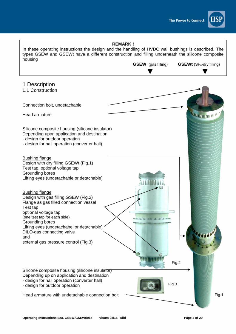
Bushings with lifting device on the flange are lifted only there (also see 2.2). In case of slight un-equilibrium the bushing is equipped with an additional counter weight (1) on the lighter head side. The size of this weight has to be equalized (Fig.9). To lift the bushing the lifting eyes have to be used. They are supplied either as removable ring screws on the flange or depending upon the design as lifting eyes fixed to the flange. Removable lifting eyes have to be removed after installation of the bushing and the threaded bores have to be closed with the plastic covers supplied. Bushings with a centre of gravity outside the flange area do not have fixed lifting devices on the flange. In this case for transport and installation in the wall a lifting jack is necessary (Fig.10), which by an adjustable arm moves the lifting point along the mass centre of gravity of the bushing. This lifting jack (Fig. 10) is made of a large clamp consisting of two parts (1), which is put around the flange, for mechanical reasons always at the end of the flange vessel. Existing test taps or valves are put in the partition of the clamp (2). The arm (3) can be rotated on the clamp (4) and with one end (5) supports itself on the flange plate. The other end is equipped with a movable part (6), which carries the lifting eye (7). The clamp is upholstered (8) to protect the welding seams against uncontrolled stress through pressure.
Nevertheless it can be necessary to apply an additional weight on of the heads for precise equilibration. The plastic foil for protection against pollution has to be removed. Do not use knives to remove it because of the danger to damage sheds.
In case there are no lifting devices like ring screws or lifting eyes on the flange, the centre of gravity of the bushing is out of flange area to such an extend that it cannot be lifted horizontally even with the help of counter weights on the ends. To mount such a bushing a lifting jack is used (Fig.10). As this lifting jack cannot be mounted on the packed bushing in its case the bushing has to be lifted by two lifting devices from its case. The second lifting device is mounted on the “top heavy” side of the bushing. Depending upon the distribution of the mass it can be necessary to use a counter weight. Also in case of bushings with lifting device on the flange.
5 1 2 3 4 6 7 8
Fig. 10
Fig. 9

Operating Instructions BAL GSEW/GSEWt/06e Visum 08/15 T/lid Page 10 of 20
2.4 Mounting of the connections
2.5 External gas pressure control
Fig.12
(only type GSEW with SF6-gas filling)
The condition of the gas filling is important for the functioning of the bushing. Gas leakage with a reducing of the pressure below the minimum operating pressure of 3.0 bar excess pressure jeopardizes the operation of the bushing! The control and remote control is made with the help of a contact manometer, which is installed in a separate, water protected housing.
Status of dispatch: (Fig.11/12)
1 Housing with installed contact manometer 2 Connection soldering sleeve for connecting tubing to the
bushing 3 Connection for signal wiring 4 Gas connection with DILO-Ventil 5 DILO-valve counter part for re-filling 6 Closing cap 7 Tubing (≥ 7 m, acc. to specification)
If the screens on the heads have not yet been mounted, they are mounted on the heads with their fastening angles. Take care that in case of the outdoor screen the water release bores are in downwards position. The lead connections for the outdoor connection and for the hall connection are performed according to the instructions of the devices to be connected. The bushing flange has to be connected to the provided grounding lead by the grounding screws in the flange. For the bushing type GSEW with SF6 filling a connection tubing has to be installed in such a way that is is protected against accidental external damages and that it leads to the mounting spot for the external pressure control (Fig.3). The connection has to be accessible outside the protective area.
The bushing is lifted and placed in front of the wall opening so that it can be inserted corresponding to the installation angle. During this procedure manual correction should be made from the ground by ropes on the bushing heads to avoid impacts on the sheds. The flange is fixed with the help of the fastening material provided by the customer. When the mounting of the bushing in the wall is completed the lifting jack is demounted.
6 5 2 4 3 1
2 7
Fig. 11

Operating Instructions BAL GSEW/GSEWt/06e Visum 08/15 T/lid Page 11 of 20
The tubing for the connection with the bushing is soldered to the soldering sleeve. Take care that the tubing is installed protected against damage.
Through the gas connection (4) pressure control for comparative measurement with the data from the manometer can be carried out and refilling can be performed. Setting values for the contact manometer are different depending upon application and installation place and are allocated to the bushing. As an example (Fig.13) the specified data for a bushing design and its contact setting. They have to be taken from the bushing specification. If the specification is not available, it has to be ordered from HSP by quoting the serial number of the bushing. In the status of dispatch the pressure gauge has no coordinate switching points. The red set pointers for the alarm contacts atre adjustable over the adjustment lock in the window with the aid of adjustment key (included in delivery) to be found on standard gauges on the outside edge of the junction box (Fig.13). The red set pointers for the alarm contacts are adjustable over the full range of the instrument. Switching points shall be set in the ranges between 10% and 90% of the scale, to ensure switching accuracy and long life of the mechanical measuring system. For transport reasons in the status of dispatch the bushing has a reduced pressure level (20 kPa). Therefore after installation of the pressure control the gas pressure has to be increased to operating pressure by re-filling additional SF6 gas (see 2.7). If the pressure control is not yet installed, connection is also possible directly at the DILO valve on the bushing (Fig. 5/9).
The setting pressure is set according to the correction table depending upon the ambient temperature of the bushing (Fig. 15).
Example
Fig. 13
Ambient temperature
°C
Setting pressure for (kPa) at 20°C
260 280 300 320 340 360 380 400 410
0 235 254 273 291 310 329 347 366 375
5 241 261 280 298 317 336 355 374 384
10 248 267 286 305 325 344 364 383 393
15 254 274 293 313 323 352 372 391 401
20 260 280 300 320 340 360 380 400 410
25 266 286 307 328 348 368 388 409 419
30 372 293 314 334 355 376 396 417 427
35 278 299 320 342 363 384 405 426 436
Fig. 14
Fig. 15

Operating Instructions BAL GSEW/GSEWt/06e Visum 08/15 T/lid Page 12 of 20
2.6 SF6-Gas release equipment
(only for GSEW with SF6 or mixed gas filling)
The equipment (Fig. 16) includes a pressure reducer unit (1) with setting handle and a manometer (3) for the pressure of the SF6 bottle and a manometer to set the pressure (4), a T-piece with angle-type non-return valve (5) and hose connection with 5 m pressure hose with DILO couplings DN8 and DN 20 (optional).
Refilling of SF6 (pure SF6) The re-filling equipment has to be connected to a common SF6 gas bottle with new gas and the valve of the bottle has to be opened. The setting handle of the pressure reducer (1) has to be turned fully to the left, i.e. it has to be closed. In its status of dispatch the re-filling device has a slight excess gas pressure to guarantee that no humidity can penetrate. This excess pressure should be kept after demounting of the device, approx. 50-100 kPa.
The valve coupling (DN8 or DN20) is connected to the bushing or to the monitoring unit. Prior to that the cap of the valve has to be removed. It is a non-return valve which opens only after the valve has been screwed to the re-filling device. On the display of the manometer (4) the pressure within the bushing can be read. After that the setting handle of the pressure reducer is opened until the required setting pressure is reached. Then the hose valve is separated from the bushing and the valve of the bushing is closed again.
Refilling of mixed gas (SF6/N2) Depending on the bushing model it is possible that the bushing design is for low temperatures (SF6/N2). Therefore please check the specification of your bushing in which are details mentioned to the mixed gas.
Use the gas release equipment as shown in clause 2.6. According to the gas proportion mentioned in the bushing specification, first of all both gases N2 and SF6 have to through a gas mixer (Fig. 17). Connect it with the gas release equipment.
Devices for gas mixing are available on the market (internet research). If you need any assistance please contact us.
Release of SF6-gas or mixed gas When SF6 is released take care that no gas is released into the environment. The gas has either to be collected in a suitable, pressure-resistant container (pressure-resistant up to 300 kPa, Vol. approx.1m3) and after that to be led to a recycling installation, or it has to be condensed in a recycling installation directly. The gas container or the recycling installation has to be connected to the hose connection of the non-return valve (5) with a pressure-resistant hose and the pressure has to be set by temporary opening and closing of the non-return valve.
Fig. 16
Fig. 17
Fig. 18
Operating Instructions BAL GSEW/GSEWt/06e Visum 08/15 T/lid Page 13 of 20
2.7 Putting SF6 filling into operating pressure
3 Putting into operation 3.1 Generel measures
3.2 Recommended tests before putting into operation
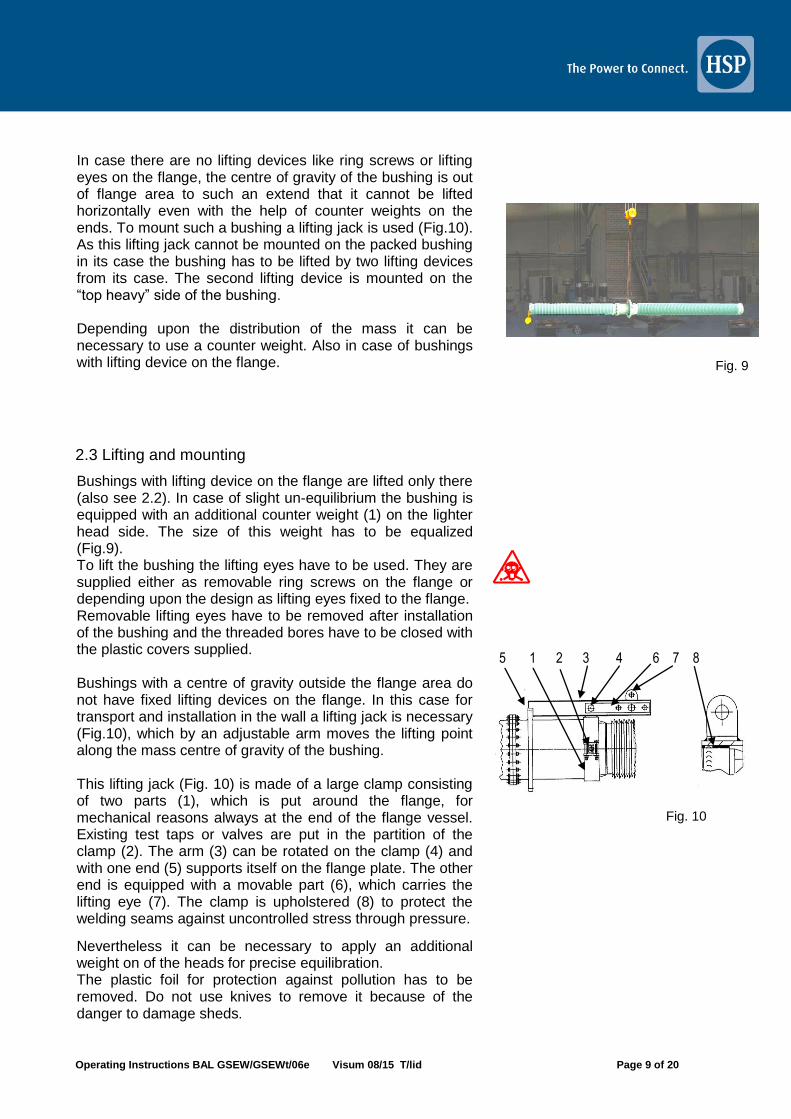
Before putting the bushing into operation with the help of the check list on the right hand side (Fig.19) it has to be checked that all steps have to be carried out correctly. Taking into consideration application in DC voltage operation and/or mixed voltage operation this control seems to be appropriate!
The checks are mentioned in the check list (Fig.19). We recommend an electrical measurement of capacitance and tan delta when the bushing is installed. The test results can be used as basic values for later comparative measurements. The values measured differ from the values in the initial routine test reports, because they include the leakage capacitance of the new bushing environment (also see 4.3).
CHECK LIST
Description Ref. see
1 Check for damages of the silicone composite housing, no damages during removal of the plastic foil?
2.2 / 2.3
2 Return of the shock indicator 2.1
3 No irregularities during insertion the bushing into the wall?
2.3
4 All silicone sheds intact? 2.3
5 Current conductor connection o.k.? Clamping connections, airside leads?
2.5
6 Correct fitting and position of the screens at the bushing head?
2.5
7 Test tap cap tightly closed? 4.3.1
8
For bushing type GSETF with gas filling control of the correct tubing. Proper soldering connections at the soldering glands?
2.5
9 Correct pressure setting acc. to ambient temperature in case of gas filling and data in the bushing specification?
2.5.1
10 Setting to operation pressure o.k.? 2.7
11 Determination of dew point to check the humidity condition of the gas filling?
3.2.1
12 Check of the setting values of the switching contacts at the manometer in the external pressure monitoring?
2.5.1
13 Connecting valves for later pressure control or re-filling available?
2.5
14 Final varnish o.k.? --
For bushings of type GSEWt with dry filling and without SF6-gas items 8 - 13 are not applicable!
(only for GSEW with SF6 or mixed gas filling)
For transport (road etc.) of the bushing the filling pressure of 20 kPa excess pressure must not be exceeded. Therefore the bushing has to be re-filled up to operating pressure before putting it into operation. Setting pressure and gas volume of the bushing are included in the respective specification. The gas density is 6.16 g/l at 20°C and 100 kPa abs. To estimate required gas quantities or quantities to be disposed of see table on the left hand side (Fig.19). Inter-values have to interpolated.
To read manometers, recording in „bar“ use 1 bar = 100 kPa
Remark: SF6 is not toxic, but heavier than air and can accumulate in holes or valleys. As a result oxygen is displaced and staying in this atmosphere can lead to suffocation.
Fig. 19

Operating Instructions BAL GSEW/GSEWt/06e Visum 08/15 T/lid Page 14 of 20
3.3 Dew point measurement
(only for GSEW with SF6-gas filling)
The gas filling of the bushing has to be dry therefore prior to putting into operation a dew point measurement to determine moisture content is necessary. It is recommended to carry out this test before the gas pressure it increased to the operating value. Thus the moisture condition in status of dispatch is determined. If it is not correct, drying can be achieved by flushing with dry N2. After that the pressure is set with dry SF6. After increase of the pressure the dew point has to be determined again and entered into the commissioning report of the bushing. Dew point measurements are carried out with corresponding devices, the measuring probe of which has to be placed in the flowing gas stream. As gas has to be refilled in any case, a mobile gas-recycling installation is an obvious choice, into which the gas of the bushing is returned by using the refilling and release equipment (2.6. Fig.16). To this tube the measuring value recorder is connected to carry out the measurement in the released gas stream. As an example for a mobile gas recycling device see Fig. 20. The dew point of the bushing gas should be – 5°C at 20° C ambient temperature (IEC 60137-value). In case of other temperatures the corrective factors have to be considered which can be taken from the files of the measuring equipment used. Example for a mobile dew point measuring device (Fig.21).
Fig. 20
Fig. 21
Beispiel

Operating Instructions BAL GSEW/GSEWt/06e Visum 08/15 T/lid Page 15 of 20
4 Maintenance 4.1 Recommended maintenance and controls
4.2 Cleaning of the insulator surface .
Fig.22
Apart from permanent gas pressure control for type GSEW with gas filling continuous maintenance of the bushings type GSEW/t is not required. On the airside of the wall bushing in certain maintenance intervals the condition of the silicone composite insulator has to be checked visually (pollution, discharge traces). In case discharge traces are detected, the cause has to be determined and, if necessary, the bushing manufacturer has to be contacted. As for bushings with gas pressure control permanent control is secured, it is recommended to check the function and the display of the manometer during the regular maintenance intervals and to secure their function. The bushing sides in converter hall operation do not require cleaning of the insulator surface, because there is no pollution. On the airside cleaning may become necessary. Especially in case of DC-loading due to the polarisation non-uniform pollution may occur.
The silicone composite insulator should not be cleaned regularly. Its good features regarding pollution are temporarily influences by cleaning, because on its surface there is a water-repellent coating, which is temporarily removed by cleaning. Cleaning is done with cloths free of fluffs and well soaked with cleaning agent. Cleaning agent: Wacker E10 of Messrs Wacker Chemie, purchase unit 25 ltr. container, consumption 1 ltr. for approx. 3 – 5 m2 of surface. After cleaning the features return to their original condition after approx. 1-2 days. An approximate statement about the condition of this so called hydrophobicity is the HC-classification shown (Fig.22). For testing purposes during wind still and dry weather an area of the size of hand has to be sprayed properly with water from a spray bottle from a distance of approx. 30 cm. The display of the drops has to be compared with the HC-table. Up to class HC3 it can be assumed that the features are sufficient for the place of installation.

Operating Instructions BAL GSEW/GSEWt/06e Visum 08/15 T/lid Page 16 of 20
Remark regarding electrical measurements on bushings for mixed
and DC voltage On site measurements are possible, but the interpretation of the measurement results is difficult and very complex, as comparative values can be used only to limited degree. Therefore it is recommended to contact the manufacturer in any case. The methods and data given provide only a rough overview.
4.3 Electrical control measurements
.
4.4 Test taps
By means of the final routine tests carried out by the manufacturer the bushing is tested suitable for operation and certified.
We recommend electrical measurements of the bushing to guarantee suitability for operation after the first 7-10 years and after that depending upon the test results in shorter intervals.
During measurements on site with a test voltage of 12 kV the bushing capacity and the tan delta are determined. The bushing capacity is an indicator for the condition of the main insulation. In case of partial punctures between the grading layers capacity changes. The degree of change provides information about the number of grading layers effected. ,
Control measurements on bushings require a certain experience with measuring equipment, test set up and interpretation of test results. For some part this is a result of the relatively small capacity values, which are locally influenced even by environment. The measurement of the dialectical dissipation factor can be influenced by humidity, weather etc (see remark on top left!).
Fig.23
But this is only a rough comparative procedure. The results do not provide any guarantee for the operating behaviour.
In addition the insulator should be checked visually for possible discharge traces. Such traces must not occur, because they damage the surface of the insulator in this area with respect to hydrophobicity. In such a case the cause for the discharges has to be determined.
Real damages of the sheds or on the body in the form of shearings cannot be repaired on site. In case of small damages repair may be possible and has to be agreed upon with the manufacturer first.
Possible larger remainders of paint can be pulled off after drying – do not use solvents!
Design of test taps on bushings of type GSEW/t (Fig. 23):
Design A older design Design B new design
The test taps are not self-grounding! Therefore during operation the cap has always to be closed tightly!
DESIGN A
Insulated bushing with pin Ø4mm Cap with O-ring sealing Grounding spring made of non-corrosive steel
DESIGN B
Cap with O-ring sealing Internal contact spring (MC-sleeve) for grounding Insulated contact spring with contact pin Ø4mm

Operating Instructions BAL GSEW/GSEWt/06e Visum 08/15 T/lid Page 17 of 20
4.5 Equipment
4.6 Measuring procedures
4.7 Limits
Fig.25
For the measurements the influence of the ambient temperature has to be taken into account. In the diagram on the right hand side for C and tan delta the variation through temperature is shown (Fig.25). For the material RIP, resin impregnated paper, there are limit values for the deviation of the capacitance and the dielectric dissipation factor with relation to the “new value” (Fig. 26). This value is reliably deducted from the reference measurement (see 3.2). In view of the small capacitance values the capacitance determined during the electrical routine test is not precise enough for the existing installation situation. If the deviation is larger than mentioned in the table Fig. 26, HSP should be contacted in any case.
Mainly the measuring procedures differ by the coupling of the measuring signal. In case of so-called “not grounded” measurements the test voltage is applied to the conductor of the bushing and the measuring signal is taken at the test tap of the bushing. The “grounded” measuring procedure for bushings without test tap is not applicable for bushings of type GSEW/t. Bushings of type GSEW with gas filling have two insulating bodies (see 1.2.2), therefore there are two test taps. Measurement is required for each test tap. The devices required for measurement are usually equipped specifically for the measurement of bushings. The measurement methods are described in comprehensive manuals.
Example for mobile test equipment
Measuring equipment is available from several manufacturers. Data can be taken from the internet or enquired at HSP (Fig.24).
ORIENTATION VALUES Rated voltage* C-Deviations (Pol-Pol AC+DC or DC) < 400 kV 3% > 400 kV 1%
tan delta 0.004 – 0.006
*see bushing specifiction
Fig.26
Fig.24
Operating Instructions BAL GSEW/GSEWt/06e Visum 08/15 T/lid Page 18 of 20
4.8 Thermo-Control by means of Thermovision
5 Storage
6 Repair Feasibility
Repair is possible in cases of:
- gas filled bushings type GSEW - replacement of sealings - investigation in case of internal failure and possible repair - bushings with dry filling GSEWt
In case of the design with gas filling GSEW the bushing can be disassembled in two parts at the joint of the vessel, above that the composite housing can be demounted.
In case of the design with dry filling GSEWt repair is restricted to the parts accessible from outside, because due to the construction disassembly of the composite housing is not possible.
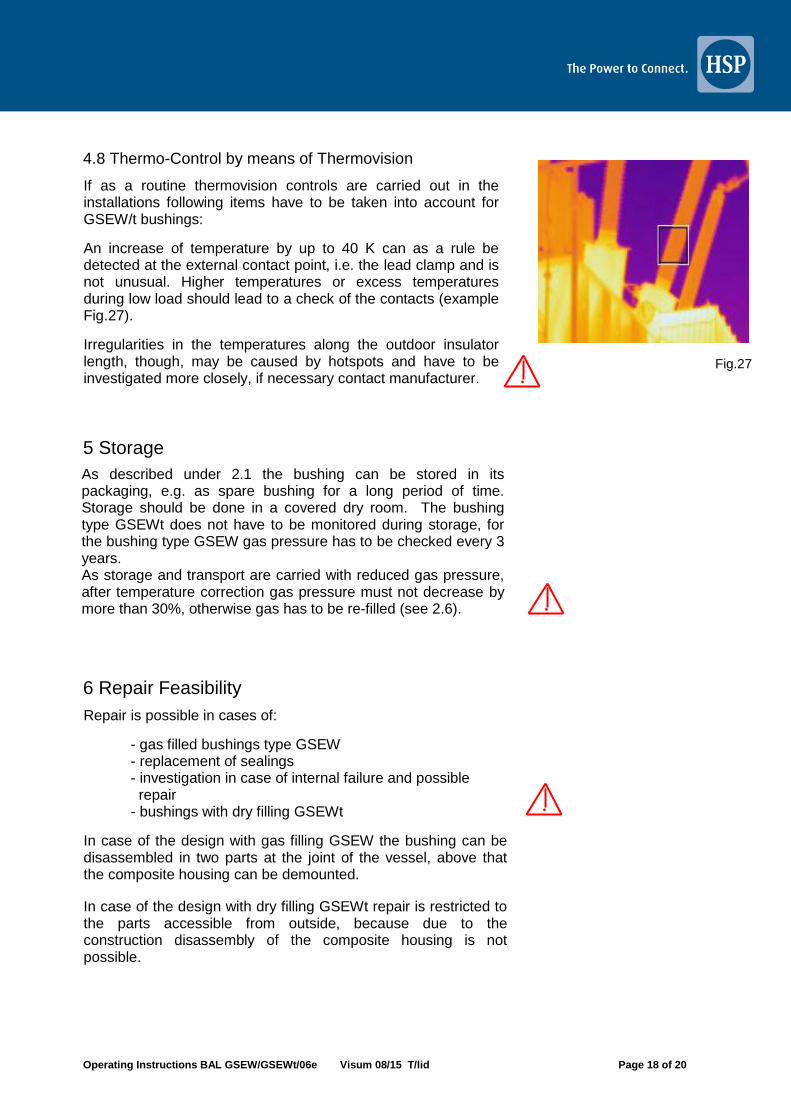
If as a routine thermovision controls are carried out in the installations following items have to be taken into account for GSEW/t bushings:
An increase of temperature by up to 40 K can as a rule be detected at the external contact point, i.e. the lead clamp and is not unusual. Higher temperatures or excess temperatures during low load should lead to a check of the contacts (example Fig.27).
Irregularities in the temperatures along the outdoor insulator length, though, may be caused by hotspots and have to be investigated more closely, if necessary contact manufacturer.
As described under 2.1 the bushing can be stored in its packaging, e.g. as spare bushing for a long period of time. Storage should be done in a covered dry room. The bushing type GSEWt does not have to be monitored during storage, for the bushing type GSEW gas pressure has to be checked every 3 years. As storage and transport are carried with reduced gas pressure, after temperature correction gas pressure must not decrease by more than 30%, otherwise gas has to be re-filled (see 2.6).
Fig.27

Operating Instructions BAL GSEW/GSEWt/06e Visum 08/15 T/lid Page 19 of 20
Fig.28
These operating and maintenance instructions are valid for both types, therefore in case of a repair different sectional drawings and parts lists for explanation are necessary. If the case occurs the documents can be ordered from HSP by quoting the serial number and the specification number and will be transmitted immediately (in English language). Example for a sectional drawing and a parts list Fig. 27. Above that depending upon repair requirements corresponding short instructions can be given.
General measures in case of repairs
a) Type GSEWt with dry filling: Disassembly is not possible, therefore repair is restricted to external damages of the silicone sheds, which are possible with the help of special procedures in case of smaller damages according to instruction of HSP or carried out by HSP.
In case of an internal failure the composite insulator has to be destroyed to allow access to the inner construction parts. We recommend to return the bushing to the manufacturer, who has suitable means and measures and professional investigation methods.
b) Type GSETF with gas filling: Sealings in the head area can be replaced when the bushing is installed and the gas pressure is reduced. We recommend to demount the bushing for works which involve the disassembly of the composite housing. Mounting has to be performed in a dry and clean room, because the inner volume of the bushing filled with SF6 has to remain free of dust.
In case of internal failures the bushing always has to be demounted. Disassembly of all parts is possible. By loosening the screw connection at the head the cover (Fig. 5/17) can be disassembled, the composite insulator can be disassembled after loosening the screw connection at the flange. It is recommended to contact HSP. Investigation on site can be carried out by HSP service personnel in a professional way.

Operating Instructions BAL GSEW/GSEWt/06e Visum 08/15 T/lid Page 20 of 20
7 Disposal after end of operation
8 Info scheme places of installation
The bushing does not contain liquids, the parts are neither toxic, self-inflammable nor physically stressing.
For better understanding of possible places of installation of bushings type GSEW/t see Fig.29.
Fig.29
Durchführung GSEW/t Freiluft-Converterhalle
Following components: - Silicone elastomere - Fibre-glass re-inforced epoxy resin - Polyurethane Elastomere (dry filling) - Epoxy resin impregnated special paper with
aluminium foils are layers - Central tube and armatures made of aluminium
alloy - Draw lead or conductor bolt made of E-Cu - Fastening elements, test tap, screws etc. made
of non-corrosive steel, aluminium alloy or brass For type GSEW with gas filling in addition the rules for handling, recycling and disposal of SF6 insulating gas have to be obeyed. As the insulating body of type GSEWt is undetachably connected to the composite housing by dry filling material, it is recommended to cut the bushing above and underneath the flange, as well as the head and the composite housing several time for better disposal.