Embed Size (px)
Citation preview
Rev. Description Date Prepared Controlled Service
Approval
0 Emission 06/02/2017 G.Testin P.Cardano M.Campana
1 Rev. Rated filling pressure value, Outline drawings & relevant
doc.18/04/2 18/04/2017 G. Testin P. Cardano M. Campana
2 Rev. Transport pressure gauge installation, management &
check list 14/03/2018 G. Testin P. Cardano M. Campana
IS 2664 GB
GE
En
erg
y C
on
ne
ction
s r
eserv
es a
ll rig
hts
in
th
is d
ocu
me
nt
an
d in t
he
in
form
atio
n
co
nta
ine
d th
ere
in. R
ep
rod
uctio
n, u
se
or
dis
clo
su
re t
o th
ird
part
ies
with
ou
t e
xp
ress a
uth
ori
za
tio
n is s
tric
tly f
orb
idde
n.
© 2
01
1 G
E E
ne
rgy C
on
ne
ctio
ns
HVDC TRANSFORMER BUSHINGS
PHI 530.1425.2500 PHI 265.850.1500
Kepco project
OPERATING
AND
MAINTENANCE INSTRUCTIONS

HVDC TRANSFORMER BUSHINGS PHI 530.1425.2500 PHI 265.850.1500
Kepco project
IS 2664 GB
Page 2 of 70
LIST OF CONTENTS
1 Introduction ................................................................................................................................ 3
2 Safety ........................................................................................................................................ 3
2.1 Safety prescriptions and operative information.................................................................... 4
3 Transport and storage conditions ............................................................................................... 6
3.1 Transport conditions ........................................................................................................... 6
3.2 Lifting conditions ................................................................................................................. 7
3.3 Storage conditions .............................................................................................................. 7
4 Technical characteristics ............................................................................................................ 8
5 Bushing preparation ................................................................................................................... 9
5.1 Bushing unpacking ........................................................................................................... 10
5.2 Bushing controls activities at the arrival ............................................................................ 11
5.3 Tools and equipment ........................................................................................................ 12
5.4 Lifting procedure ............................................................................................................... 14
5.4.1 Lifting tools installation ............................................................................................... 14
5.5 Bushing installation on the transformer ............................................................................. 15
6 Bushing oil characteristics and accessories ............................................................................. 17
6.1 Oil pressure vs average temperature ................................................................................ 18
6.2 Oil pressure gauge ........................................................................................................... 18
6.3 PHI Bushing filtering & bypass valves ............................................................................... 19
7 Transformer turret arrangement and oil parameters ................................................................. 21
8 Gas SF6 characteristics and gas filling instructions.................................................................. 24
8.1 Gas first filling operation and control of alarm and tripping signals .................................... 25
8.2 Gas refilling during the bushing normal operation ............................................................. 25
8.3 Gas characteristics before the energization ...................................................................... 26
9 Procedure for bushing gas compartment decontamination ....................................................... 26
9.1 Procedure for bushings equipped with the gas filling station ............................................. 26
9.2 Procedure for bushings not equipped with the gas filling station ....................................... 27
10 Gas density monitor ............................................................................................................. 27
11 Power factor tap ................................................................................................................... 28
12 Voltage divider unit ............................................................................................................... 29
13 Composite insulators maintenance ....................................................................................... 30
14 General maintenance plan ................................................................................................... 32
15 Disposal at the end of life ..................................................................................................... 34
Appendix 1 – Bushing outline drawing ............................................................................................ 36
Appendix 2 – Electrical scheme ...................................................................................................... 38
Appendix 3 – Lifting tools ................................................................................................................ 52
Appendix 4 – Gas density monitor Electronsystem ......................................................................... 60
Appendix 5 – Oil pressure gauge .................................................................................................... 65
Appendix 6 - Composite insulators maintenance and repairing ....................................................... 66
Appendix 7 – Bushing installation check list .................................................................................... 67
Appendix 8 – Gas filling check list ................................................................................................... 70

HVDC TRANSFORMER BUSHINGS PHI 530.1425.2500 PHI 265.850.1500
Kepco project
IS 2664 GB
Page 3 of 70
1 Introduction These instructions are applicable to the hybrid type HVDC transformer bushings of the PHI series and provide all information relevant to:
• Safety aspects.
• Transport conditions.
• Technical characteristics.
• Controls at the arrival and preparation activities.
• Lifting and installation operation.
• Oil filtering and recirculation.
• Gas filling operation.
• Service and maintenance plan and procedures.
The PHI bushings are manufactured and tested in compliance with the following standards:
IEC 62199 – 2004 Bushings for DC application.
IEC 60137 - 2003 Insulated bushings for alternating voltages above 1000V.
2 Safety In this document important safety requirements are highlighted by the word WARNING. Mandatory safety actions are evidenced by the word OBLIGATION, while important operative instructions are evidenced by the word NOTE. This manual must be available to the personnel responsible of the installation, operation and maintenance of the bushings. The transformer bushing is a high voltage DC device, filled under pressure with SF6 gas, that realizes the interface between the transformer and the convertor. The arrangement of the bushing allows the passage through the wall of the valve building. The preparation and the installation of the bushing, the oil filtering and treatment process, the gas filling and the periodical maintenance operations must be performed by qualified operators. They have to be trained to operate in accordance with the guidelines described in this instruction manual. Every operator must use the prescribed tools and the prescribed safety devices. Non-compliance with the following procedures and instructions can result in serious and dangerous situations for the personnel and in risks of damages of the equipment and the property and environment pollution.

HVDC TRANSFORMER BUSHINGS PHI 530.1425.2500 PHI 265.850.1500
Kepco project
IS 2664 GB
Page 4 of 70
Main safety risks related to the bushing handling and its operative conditions are:
• Transport and handling of heavy and large parts.
• Lifting and moving of heavy and not well-balanced goods.
• Work operations under the crane and suspended materials.
• Work at height. All operation at height must be performed on a suitable certified platform.
• Risk of falling down of heavy parts during the installation.
• Risks deriving from un-proper balancing of the masses that can cause un-expected rotation during the installation of the bushing on the transformer or on the test turret.
• Risks related to the use of un-proper tools or wrong operations. • Risks deriving from un-proper installation or operation on the bushing when filled by SF6 gas at rated
filling pressure (risk of explosion).
• Environmental risks related to dispersion of SF6 gas in the atmosphere or mineral oil in the environment.
• Severe electrical shock risk related to the extremely high voltage DC level of the equipment.
• Severe electrical shock risk due to un-proper realization of the bushing grounding connections.
• Severe electrical shock risks deriving by the fact that the composite insulator and the other main parts of the bushing remain electrically charged at high voltage for a long period of time after the plant de-energizing and the bushing grounding. Before starting any work on the de-energized bushing, check the discharge by touching all surface of the composite insulator and all other parts of the bushing with an insulated grounding rod which length must be ≥ 3m. During this operation the workers must wear protective insulating gloves and boots and helmets with protective transparent face shield.
2.1 Safety prescriptions and operative information
The following notes are mandatory for personnel involved in transformer bushing installation. All problems detected during the bushing installation must be reported to the Foreman and to GE Energy Connections RPV Supervisor.
WARNING: The PHI bushing is a gas pressurized device. Operations on valves, pressure gauges, pipes, protective devices must be performed by qualified operators, with the proper equipment. Foreman and operators have to take careful for handling the pressurized equipment. It is strictly forbidden to move, lift and install equipment that is under pressure. Check through appropriate gauge that the gas side of the bushing is at a pressure less than or equal to 0.125 MPa abs (0.25 bar gauge) before operate on it.
WARNING: Never use damaged or not certified lifting equipment.
WARNING: Lifting equipment must be under a planned maintenance routine. Operators must be qualified and properly trained.
WARNING: Work in quote will be done by trained operators on adequate and certified moving platforms. Workers that will operate in quote must use the prescribed safety devices and in addition they must wear certified safety harnesses.
WARNING: Lifting equipment will be entrusted only to specialized personnel, kept in efficiency and clean. Identification and rating plates must be always present and visible on the equipment. Do not use the equipment when rating plates are missed or unreadable.
WARNING: The equipment is filled with SF6 gas. This gas is not environmentally friend. Always use an appropriate gas filling machine that allows the SF6 recovery. Avoid any dispersion of the gas in the environment.
HVDC TRANSFORMER BUSHINGS PHI 530.1425.2500 PHI 265.850.1500
Kepco project
IS 2664 GB
Page 5 of 70
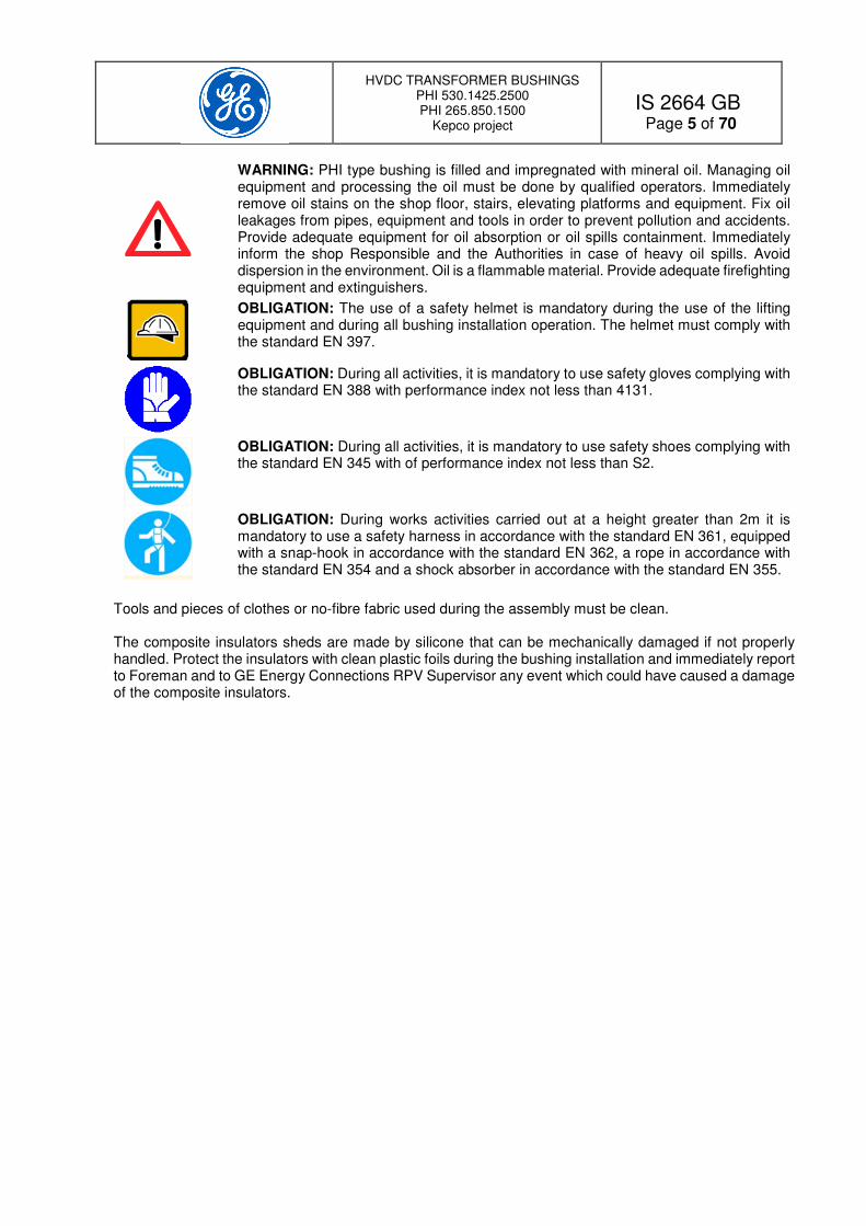
WARNING: PHI type bushing is filled and impregnated with mineral oil. Managing oil equipment and processing the oil must be done by qualified operators. Immediately remove oil stains on the shop floor, stairs, elevating platforms and equipment. Fix oil leakages from pipes, equipment and tools in order to prevent pollution and accidents. Provide adequate equipment for oil absorption or oil spills containment. Immediately inform the shop Responsible and the Authorities in case of heavy oil spills. Avoid dispersion in the environment. Oil is a flammable material. Provide adequate firefighting equipment and extinguishers.
OBLIGATION: The use of a safety helmet is mandatory during the use of the lifting equipment and during all bushing installation operation. The helmet must comply with the standard EN 397.
OBLIGATION: During all activities, it is mandatory to use safety gloves complying with the standard EN 388 with performance index not less than 4131.
OBLIGATION: During all activities, it is mandatory to use safety shoes complying with the standard EN 345 with of performance index not less than S2.
OBLIGATION: During works activities carried out at a height greater than 2m it is mandatory to use a safety harness in accordance with the standard EN 361, equipped with a snap-hook in accordance with the standard EN 362, a rope in accordance with the standard EN 354 and a shock absorber in accordance with the standard EN 355.
Tools and pieces of clothes or no-fibre fabric used during the assembly must be clean. The composite insulators sheds are made by silicone that can be mechanically damaged if not properly handled. Protect the insulators with clean plastic foils during the bushing installation and immediately report to Foreman and to GE Energy Connections RPV Supervisor any event which could have caused a damage of the composite insulators.

HVDC TRANSFORMER BUSHINGS PHI 530.1425.2500 PHI 265.850.1500
Kepco project
IS 2664 GB
Page 6 of 70
3 Transport and storage conditions The bushing is shipped in a wooden box suitable for marine transport, designed to provide protection of the bushing in accordance with the specified transport conditions. The complete crate must be lifted, loaded on vehicles and transported with great care to prevent damages of the bushing or its accessories. Stacking of crates is not allowed. Shock indicators are fixed on the crate walls. GE Energy Connections RPV will not respond of any damage due to un-proper operations. The total mass of the bushing packed and crates dimensions, as a function of the type, are listed in Table 1. Centre of gravity and lifting points are painted on the crate walls. Top electrostatic shields are shipped in separate crates.
Bushing type Crate mass
[kg]
Dimensions L x W x H
[cm] PHI 530 kV 4300 1020x170x220
PHI 265 kV 2500 800x120x220
Table 1 – Bushing mass and crate dimensions by bushing type 3.1 Transport conditions The bushing can be transported by truck, ship, airplane. The bushing is filled with SF6 gas at a pressure of 0.125 MPa abs (0.25 bar gauge) and mineral oil at a pressure of 1 bar gauge at 20°C (see curve in Figure 8). To check the gas pressure during the transportation or the long storage conditions, the bushing is equipped with a Transport pressure gauge (see Figure 1) installed on a Dilo valve. This device must be removed during the installation phase on the transformer, before the bushing filling at rated pressure and it has to be reused for the bushing shipment at site. In order to prevent dangerous movement of the crate during the transport it is responsibility of the transport company to carefully fix it on the vehicle by suitable retain systems like ropes, synthetic pulling bands or any other method. The maximum allowed transport acceleration along the three axis is 5g (49.05 m/s2). In case of transport by truck along very bad roads (‘bumpy roads’) the speed must be adequately reduced to max 30 km/h. Trucks to be used for road transportation must have a platform of sufficient dimensions to accommodate the overall crate. Crate overhang from any platform and hauling are not allowed. The top of the crate is protected by a PE tarpaulin suitable for protection from rain. During the transport by road or ship the good must be protected from rain, sea water and other exceptional environment conditions by additional tarpaulins, not provided by GE Energy Connections RPV, suitable to cover completely the crate. Sea transportation on the ship main deck is allowed providing the above mentioned additional protection. Transportation in ship hold is preferred.
Figure 1 – Transport pressure gauge WARNING: The Transport pressure gauge must be removed from the bushing before the gas filling operation at rated pressure. It must be used only at the transport pressure value. Higher pressures will damage it.

HVDC TRANSFORMER BUSHINGS PHI 530.1425.2500 PHI 265.850.1500
Kepco project
IS 2664 GB
Page 7 of 70
3.2 Lifting conditions Lifting operation must be done by qualified operators and with certified ropes and equipment. Lifting points are indicated on the crate and are reinforced by steel plates (see Figure 2). Lifting the crate by fork lift is not allowed.
Figure 2 – Crate lifting arrangement
WARNING: The centre of gravity point of the crate could be not perfectly centred respect the crate geometry. Care must be taken during the lifting and moving operation to prevent dangerous situations, damages or heavy shocks to the good. 3.3 Storage conditions For short period storage, up to 1 month, the package can be stored outside, just protected by a suitable additional tarpaulin. The storage area must have a concrete floor made in such a way to ensure a sufficient drainage of water. For long time storage, it is necessary that the whole crate is placed inside a suitable warehouse and that a periodical check, every six months, of the bushing, the gas pressure and of relevant accessories will be activated. In this case, it is also recommended to increase the gas pressure to 0.5 bar gauge (0.150 MPa abs). GE Energy Connections RPV must be informed concerning the activation of the long storage condition. The periodical controls must verify the bushing conditions, the gas pressure and its dew point and the overall status of the electric instruments, the accessories and tools. All data must be recorded in a specific check list. NOTE: Violation of the above prescriptions will cause the immediate termination of the warranty. If the bushing is installed on the transformer and the complete transformer is stored as spare unit, it is necessary to perform the following actions:
• Set the gas pressure to 0.5 bar gauge (0.150 MPa abs).
• Protect the composite insulator with a PE double thickness bag.
• Remove the top toroids and wrap them in bubble PE foils then put them in a suitable wooden box to be stored in a covered warehouse.
• Record the gas pressure and the oil pressure and the ambient temperature for future reference.
• Control and protect the pressure gauges, PF tap and relevant accessories with PE foils and silica gel bags.
• Seal all cable passages from the electrical cubicles and protect them with PE foils and silica gel bags.
• Activate a periodical check, at least every six months, to check the status of the bushing, the gas pressure that must be ≥ 0.3 bar gauge (0.13 MPa abs) and oil pressure.

HVDC TRANSFORMER BUSHINGS PHI 530.1425.2500 PHI 265.850.1500
Kepco project
IS 2664 GB
Page 8 of 70
4 Technical characteristics
PHI bushings are based on the hybrid technology. This means that the bushing is based on two different insulation technologies: The first, based on an Oil Impregnated Paper (OIP in the document) grading capacitor, realizes the interface with the transformer. The second, based on a gas insulated section, realizes the interface to the converter plant. The bushing, filled at rated filling pressure with pure SF6 gas, is designed to operate at low temperatures down to -25° C.
The Hybrid solution offers the following advantages:
• Complete separation between the gas compartment and the transformer turret. Gas leakages to the transformer are not possible and they are detected by suitable pressure gauges at the level of the OIP capacitor section.
• Full prevention of transformer oil spills into the valve hall due to the particular bushing structure.
• The mineral oil inside the grading capacitor OIP section provides an optimum cooling of the conductor with excellent performances in case of high current ratings and harmonics presence.
• The grading capacitor winding is 100% protected from the risk of pollution during the bushing installation on the transformer, as it is fully sealed by special fibreglass barriers.
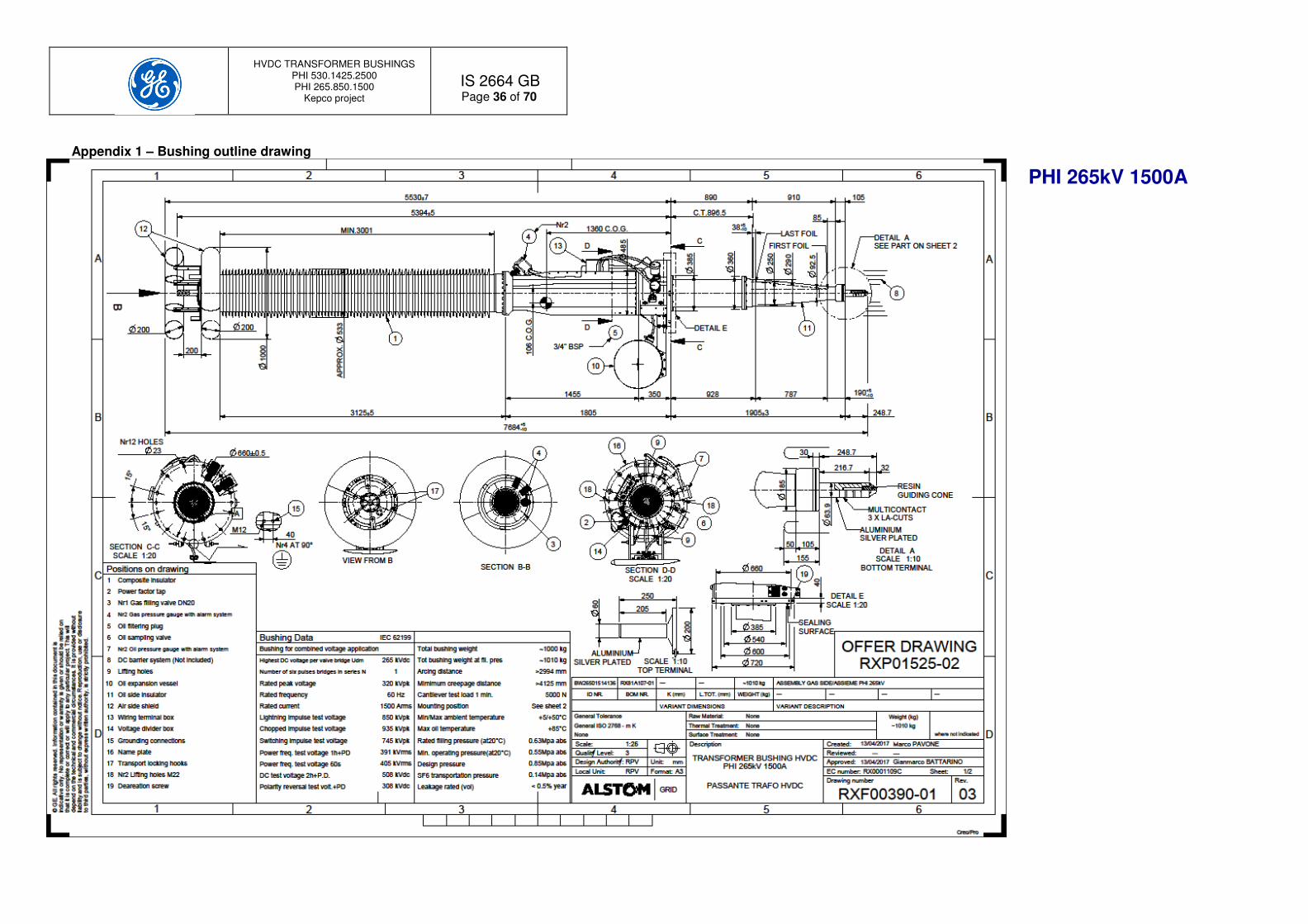
Next Table 2 reports the main electrical technical characteristics of the two bushing types and Table 3 reports the design environmental conditions. The complete outline drawings of the two bushing types are shown in Appendix 1.
Bushing type PHI 530.1425.2500 PHI 265.850.1500
Voltage ratings Rated continuous d.c. voltage per valve bridge Udm Number of six pulses bridges in series N Rated continuous a.c. voltage Maximum continuous a.c. voltage Uvm
265
2 220 230
265
1 220 230
kVdc kV line to line kVrms
Current rating Rated current Distorted operation harmonics current
2500
See tech spec.
1500
See tech spec. Arms
Short circuit level 34 34 kApk
Rated frequency 60 60 Hz
Lightning impulse withstand (BIL) 1425 850 kVpk
Chopped wave 1567.5 935 kVpk
Switching impulse dry withstand (SIL) 1217 745 kVpk
DC 2h voltage test 964 508 kVdc
Polarity reversal test 688 308 kVdc
Power frequency withstand (1 min) 679 405 kVrms
AC PD test (1 hour) 715 391 kVrms
Rated filling pressure @ 20°C 0.63 0.63 MPa abs
Table 2 – Bushing electrical characteristics

HVDC TRANSFORMER BUSHINGS PHI 530.1425.2500 PHI 265.850.1500
Kepco project
IS 2664 GB
Page 9 of 70
Bushing type PHI 530.1425.2500 PHI 265.850.1500
Ambient conditions: Max valve hall temperature Min valve hall temperature Max transformer oil temperature
+ 50
+5 +85
+ 50
+5 +85
°C °C °C
Pollution condition Indoor
Very low
Very low
Minimum creepage distance Indoor
>10080
>4125
mm
Minimum arcing distance Indoor
>4728
>2994
mm
Seismic condition 0.225 0.225 g
Altitude above sea level (up to) <1000 <1000 m
Installation angle 23°-33° 23-°40° From horizontal
Table 3 – Environmental conditions
5 Bushing preparation All operators involved in components unpacking and assembly have to be careful not to damage the objects. During the unpacking operation, it is necessary to check that all components supplied by GE Energy Connections RPV are available and not damaged during the transportation. All incoming goods must be stored in a covered area and prepared for the installation. At the arrival, the crate must be inspected. Any damage of the crate or indication of the visual external shock indicator (see Figure 3) must be reported to the Foreman and GE Energy Connections RPV Supervisor.
Figure 3 – Visual external shock indicator A detailed control check list is listed in Table 4 at Paragraph 5.2.

HVDC TRANSFORMER BUSHINGS PHI 530.1425.2500 PHI 265.850.1500
Kepco project
IS 2664 GB
Page 10 of 70
5.1 Bushing unpacking The crate is provided with a lid made in sections. Each section is provided with four lifting eyebolts placed at the four corners. On the crate side walls, there are two lines of screws. The upper line of screws is those that hold the lids. Remove all the upper screws that hold the cover to the crate walls (see Figure 4). Connect the lifting ropes to the eyebolts and remove the three lid sections (see Figure 5). After the removal of the top lid, remove the crate upper wooden beams that provide support the top lid, then remove the plastic foils that covers the bushing but do not remove the PE layer wrapped on the composite insulator. Inside the crate, the bushing is locked at the level of the central and the top flange by locking belts and bolts.
Figure 4 – Lid sections locking screws Figure 5 – Removing the lid sections
WARNING: Composite insulator and the oil side fibreglass cone are protected by a PE plastic foils. Remove the protection on the composite insulator only just before the transformer energization. The oil side cone protection must be removed only just before the installation of the bushing on the transformer turret. WARNING: It is not allowed to step on the composite insulators. The silicone sheds can be seriously damaged. WARNING: The centre of gravity point is not centred respect the bushing geometry. Care must be taken to compensate the mass unbalancing before and during lifting operations. WARNING: Never wrap ropes (i.e. ‘tie’ lifting method) around the silicone sheds. The composite insulators will be seriously damaged.
Remove these screws
Do not remove these screws

HVDC TRANSFORMER BUSHINGS PHI 530.1425.2500 PHI 265.850.1500
Kepco project
IS 2664 GB
Page 11 of 70
5.2 Bushing controls activities at the arrival
Item Control Description Actions on problems
1 Crate inspection Check for evidence of shocks on the crate structure. Check the status of the external shock indicators.
• Take pictures of evidences.
• In case of deviations notify the Foreman and the GE Energy Connections RPV Supervisor.
• Continue with the internal inspection.
2 Gas filling residual pressure and gas dew point
Check gas pressure: 0.11 MPa abs ≤ Gas pressure ≤0.125 MPa abs
(0.1 bar gauge ≤ Gas pressure ≤0.25 bar gauge) Check gas dew point ≤ -30°C @ atmospheric pressure.
• Record the pressure value and the gas dew point
• In case of deviations notify the Foreman and the GE Energy Connections RPV Supervisor.
• Continue with the inspection but: Wait for instructions.
3 Oil pressure Check if the oil pressure ≥1 bar gauge @20°C (see Figure 8).
• Record the pressure and the average bushing temperature.
• In case of deviations notify the Foreman and the GE Energy Connections RPV Supervisor.
• Check for oil leakages.
• Continue with the inspection but: Wait for instructions.
4 Bushing inspection Check the integrity of the oil side cone. Check the bottom terminal and the MultiContact blades. Check the flange and the gas and oil pressure gauges. Check the oil expansion vessels, the oil pipes and all oil valves. Check the wiring and the electrical circuit. Check the integrity of the valves warranty seals and red warning tags. Check for oil leakages. Check the status of the composite insulator and the silicon sheds. Check the top terminal. Check the toroids and relevant accessories.
• Take pictures of the various inspected parts.
• In case of deviations notify the Foreman and the GE Energy Connections RPV Supervisor.
• Continue with the inspection but: Wait for instructions.
Table 4 – Bushing controls activities at the arrival
HVDC TRANSFORMER BUSHINGS PHI 530.1425.2500 PHI 265.850.1500
Kepco project
IS 2664 GB
Page 12 of 70
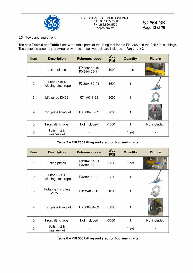
5.3 Tools and equipment The next Table 5 and Table 6 show the main parts of the lifting tool for the PHI 265 and the PHI 530 bushings. The complete assembly drawing relevant to these two tools are included in Appendix 3
Item Description Reference code WLL [kg]
Quantity Picture
1 Lifting plates RX380468-10 RX380468-11
1000 1 set
2 Tirfor T516 D
including steel rope RX38A162-01 1600 1
3 Lifting lug DN22 RX1A013-22 2000 1
4 Front plate lifting kit RX380463-02 2000 1
5 Front lifting rope Not included >1000 1 Not included
6 Bolts, nut & washers kit
- - 1 set -
Table 5 – PHI 265 Lifting and erection tool main parts
Item Description Reference code WLL [kg]
Quantity Picture
1 Lifting plates RX38A164-01 RX38A164-02
2500 1 set
2 Tirfor T532 D
including steel rope RX38A162-02 3200 1
3 Rotating lifting lug
ADA 12 RX22A060-10 1000 1
4 Front plate lifting kit RX380464-03 3000 1
5 Front lifting rope Not included >3000 1 Not included
6 Bolts, nut & washers kit
- - 1 set -
Table 6 – PHI 530 Lifting and erection tool main parts

HVDC TRANSFORMER BUSHINGS PHI 530.1425.2500 PHI 265.850.1500
Kepco project
IS 2664 GB
Page 13 of 70
Bolts and nuts of the lifting tools must be tightened at torque values listed in the following Table 7.
Screw / nut type
Tightening Torque [Nm]
M12 60
M24 229
M30 460
Table 7 – Screws and nut tightening torques
To lift and install the bushings on the transformer the lifting crane shall have the following minimum characteristics:
Solution with one overhead crane
• Single grinder crane.
• Crane capacity ≥ 2.5 t.
• Hoist lifting height ≥ 12m.
• Slow hoisting speed ≤1.3 m/min.
Or, as an alternative:
N. 1 mobile telescopic crane with the following technical characteristics:
• Single crane.
• Lifting boom working length ≥ 17m.
• Hoist lifting height ≥12m.
• The capacity of the crane must comply with the characteristics indicated in with the following Figure 6.
The crane operative working conditions must be within the limits set by the red area.
Figure 6 – Mobile crane working characteristics

HVDC TRANSFORMER BUSHINGS PHI 530.1425.2500 PHI 265.850.1500
Kepco project
IS 2664 GB
Page 14 of 70
5.4 Lifting procedure This paragraph refers to the bushing removal from the transport crate. All references are to the tool lists in Table 5 for the PHI 265 and Table 6 for the PHI 530 and to the drawings RX380466-01 and RX380466-02 in Appendix 3 WARNING: Before proceeding with the installation of the bushing on the transformer, it is necessary that the bushing gas pressure is set at the transport value (0.25 bar gauge, 0.125MPa abs).
5.4.1 Lifting tools installation
To install the lifting tools, it is necessary to follow this procedure
Remove the crate walls. Check that the bushing pressure is set at the transport pressure level.
• Install the Lifting Plates (Item 1) on the bushing flange.
• Firmly tighten the bolts & nuts at the prescribed torque (see Table 7).
• Install the lifting lug (Item 3) on the Lifting Plates and lock it carefully.
PHI 265
PHI 530
• Install the Front Plate lifting kit (Item 4).
• Firmly tighten the bolts & nuts at the prescribed torque (see Table 7).
• Control the correct locking on the lifting lugs before installing the ropes.
PHI 265
PHI 530
• Install the Tirfor (Item 2) with its built-in ropes on the Lifting Plates (Item 1).
• Connect the other side of the Tirfor rope to the hook crane.
• Connect the Front lifting rope (Item 5) to the Front Plate lifting kit (Item 4).
This side UP
HVDC TRANSFORMER BUSHINGS PHI 530.1425.2500 PHI 265.850.1500
Kepco project
IS 2664 GB
Page 15 of 70
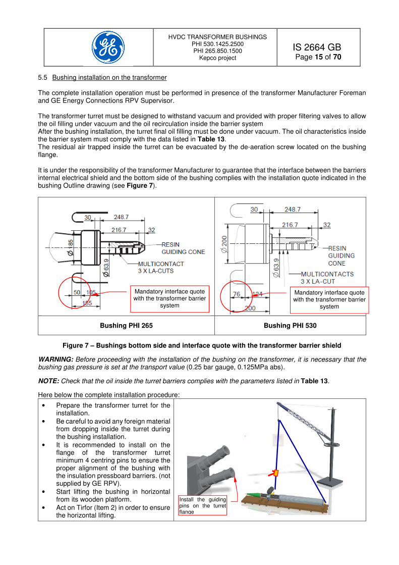
5.5 Bushing installation on the transformer The complete installation operation must be performed in presence of the transformer Manufacturer Foreman and GE Energy Connections RPV Supervisor. The transformer turret must be designed to withstand vacuum and provided with proper filtering valves to allow the oil filling under vacuum and the oil recirculation inside the barrier system After the bushing installation, the turret final oil filling must be done under vacuum. The oil characteristics inside the barrier system must comply with the data listed in Table 13. The residual air trapped inside the turret can be evacuated by the de-aeration screw located on the bushing flange. It is under the responsibility of the transformer Manufacturer to guarantee that the interface between the barriers internal electrical shield and the bottom side of the bushing complies with the installation quote indicated in the bushing Outline drawing (see Figure 7).
Bushing PHI 265 Bushing PHI 530
Figure 7 – Bushings bottom side and interface quote with the transformer barrier shield
WARNING: Before proceeding with the installation of the bushing on the transformer, it is necessary that the bushing gas pressure is set at the transport value (0.25 bar gauge, 0.125MPa abs).
NOTE: Check that the oil inside the turret barriers complies with the parameters listed in Table 13.
Here below the complete installation procedure:
• Prepare the transformer turret for the installation.
• Be careful to avoid any foreign material from dropping inside the turret during the bushing installation.
• It is recommended to install on the flange of the transformer turret minimum 4 centring pins to ensure the proper alignment of the bushing with the insulation pressboard barriers. (not supplied by GE RPV).
• Start lifting the bushing in horizontal from its wooden platform.
• Act on Tirfor (Item 2) in order to ensure the horizontal lifting.
Install the guiding pins on the turret flange
Mandatory interface quote with the transformer barrier
system
Mandatory interface quote with the transformer barrier
system

HVDC TRANSFORMER BUSHINGS PHI 530.1425.2500 PHI 265.850.1500
Kepco project
IS 2664 GB
Page 16 of 70
• Lift the bushing in horizontal position up to 2 m from the floor.
• Start inclining the bushing by acting on the Tirfor (Item 2).
• Continuously check during the inclining operation that the bottom part of the bushing will not hit the floor or any other part.
• Check the correct inclination on the transformer side of the bushing flange angle by a Quadranfix inclinometer or by an electronic inclination gauge (not supplied by GE RPV).
• Control with the same instrument the effective inclination angle of the transformer turret flange and adjust the bushing inclination angle accordingly by acting on the Tirfor (Item 2).
• When the bushing axis will coincide to the turret axis and the inclination angle is OK, slowly proceed with the bushing insertion inside the turret.
• By continuously controlling that the turret and the bushings are aligned, gradually insert the bushing inside the transformer turret.
NOTE: During this operation, it is mandatory to continuously check that the bushing cone will remain centred respect the turret flange and the CT coils arrangement, normally placed inside the turret. Check that there are no interferences and that no damages or scratches occur on the cone and the metal parts of the oil side of the bushing. In case of damages, immediately contact GE Energy Connections RPV Supervisor and the Foreman and stop the operation.
• Complete the installation of the other bushings and after the completion of the transformer preparation, install the electrostatic top shields on the bushings.
• Fill the bushing with SF6 (see Chapter 8).
• Complete all relevant activities for the transformer preparation.
WARNING: Before proceeding with the gas filling operation, remove the Transport pressure gauge (see Paragraph 3.1 and Figure 1).
Quadranfix inclinometer

HVDC TRANSFORMER BUSHINGS PHI 530.1425.2500 PHI 265.850.1500
Kepco project
IS 2664 GB
Page 17 of 70
6 Bushing oil characteristics and accessories The PHI bushings are filled Nynas Nytro 4000 A mineral oil. The same type of oil must be used in case of re-filling or oil reprocessing. At the end of the drying and impregnation process in GE factory, the bushing oil parameters are in accordance with the data listed in the following Table 8.
Parameter Limit Water content by Karl Fisher at 20°C ≤ 2 ppm
Breakdown voltage on 2.5 mm gap ≥ 80 kV
Total gas content ≤ 200 ppm (0.02%)
Total combustible gases < 10 ppm (0.001%)
Power factor at 90°C ≤ 0.0025
Resistivity at 30°C ≥15 1012 Ohm x m
Particle content ISO11218 Class 00
Table 8 – Oil parameters for final oil filling and recirculation at the factory production
Concerning the ISO 11218 solid contamination limits classes, next Table 9 summarizes the quantities and the size limits for each class.
Classes
Maximum Contamination Limits (particles/100ml)
ISO 11218 > 4 µm(c)
> 6 µm(c)
>14 µm(c)
> 21 µm(c)
> 38 µm(c)
> 70 µm(c)
000 195 76 14 3 1 0
00 390 152 27 5 1 0
0 780 304 54 10 2 0
1 1560 609 109 20 3 1
2 3120 1220 217 39 6 1
3 6250 2430 432 76 11 2
4 12500 4960 864 152 22 4
5 25000 9730 1730 306 45 8
6 50000 19500 3460 6012 90 16
7 100000 38900 6920 1220 180 32
8 200000 77900 13900 2450 360 64
9 400000 156000 27700 4900 720 128
10 800000 311000 55400 9800 1440 256
11 1600000 623000 111000 19600 2880 512
12 3200000 1250000 222000 39200 5760 1024
Table 9 – Solid contamination limits classes according ISO 11218
NOTE: The excellent quality of the oil process in the factory is such that the bushing does not require any additional oil treatment before the transformer tests or before the installation on site.
HVDC TRANSFORMER BUSHINGS PHI 530.1425.2500 PHI 265.850.1500
Kepco project
IS 2664 GB
Page 18 of 70
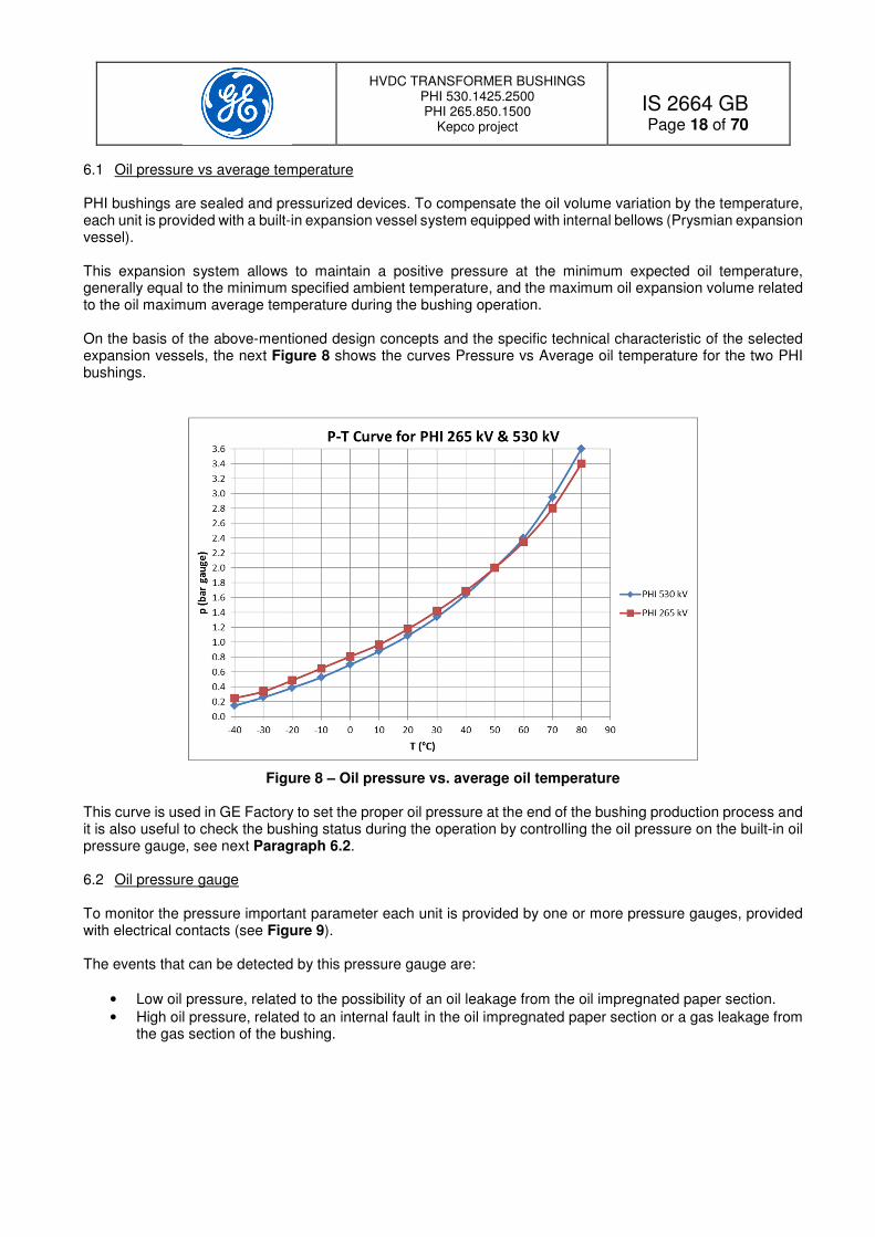
6.1 Oil pressure vs average temperature PHI bushings are sealed and pressurized devices. To compensate the oil volume variation by the temperature, each unit is provided with a built-in expansion vessel system equipped with internal bellows (Prysmian expansion vessel). This expansion system allows to maintain a positive pressure at the minimum expected oil temperature, generally equal to the minimum specified ambient temperature, and the maximum oil expansion volume related to the oil maximum average temperature during the bushing operation. On the basis of the above-mentioned design concepts and the specific technical characteristic of the selected expansion vessels, the next Figure 8 shows the curves Pressure vs Average oil temperature for the two PHI bushings.
Figure 8 – Oil pressure vs. average oil temperature This curve is used in GE Factory to set the proper oil pressure at the end of the bushing production process and it is also useful to check the bushing status during the operation by controlling the oil pressure on the built-in oil pressure gauge, see next Paragraph 6.2. 6.2 Oil pressure gauge To monitor the pressure important parameter each unit is provided by one or more pressure gauges, provided with electrical contacts (see Figure 9). The events that can be detected by this pressure gauge are:
• Low oil pressure, related to the possibility of an oil leakage from the oil impregnated paper section.
• High oil pressure, related to an internal fault in the oil impregnated paper section or a gas leakage from the gas section of the bushing.

HVDC TRANSFORMER BUSHINGS PHI 530.1425.2500 PHI 265.850.1500
Kepco project
IS 2664 GB
Page 19 of 70
Figure 9 – Oil pressure gauge Each instrument is equipped with 4 Normally Open micro-switches that provide alarm / tripping signals. Table 10 shows the micro switches purpose and the pressure set up.
Micro switch Description Pressure set up
[bar gauge] [MPa gauge]
Low pressure Tripping
Too low pressure for operation 0.2 0.02
Low pressure Alarm
Low pressure related to low oil level
0.4 0.04
High pressure Alarm
Overpressure inside the OIP section
2.6 0.26
High pressure Tripping
Too high pressure inside the OIP section for operation
2.8 0.28
Table 10 – Alarm and tripping micro switches set-up The pressure gauge is installed on a ball type valve for easy replacement in case on need and all electrical cables are wired in the junction box provided with DIN type terminal blocks (see Appendix 2). Additional information about the oil pressure gauge device are in illustrated in Appendix 5. 6.3 PHI Bushing filtering & bypass valves PHI bushings are equipped with a special valve system located at the level of the central flange that allows:
• The oil filling under vacuum.
• The oil recirculation for filtering and the oil passage during the normal operation. NOTE: Operation on the valves must be done by qualified and authorized operators only. Depending on their specific function, they are named filtering and by-pass valves (see Figure 10). These valves are installed inside some metallic protrusions on the bushing flange, protected by metal lids (see Figure 11). The number of valve blocks is related to the size of the bushing.

HVDC TRANSFORMER BUSHINGS PHI 530.1425.2500 PHI 265.850.1500
Kepco project
IS 2664 GB
Page 20 of 70
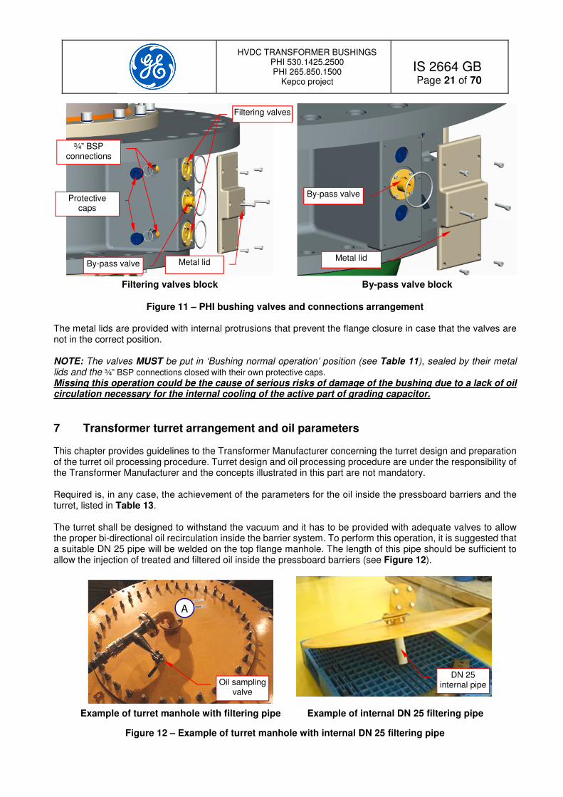
The valve blocks can be of two types, the type named Filtering valve block, that includes three different valves (see Figure 10 a) and the type named By-pass valve block, that includes the by-pass valve only (see Figure 10 b).
a) Filtering valves block b) By-pass valve block
Figure 10 – PHI bushing valves Vacuum pump and oil filling and filtering equipment can be connected to the filtering valves through two ¾” BSP connections placed on the side of each filter valve block. These connections are protected by a removable cap (see Figure 11). By-pass valves are placed in both type of blocks and are necessary to ensure the proper oil circulation during the normal bushing operation. The by-pass valve blocks are not equipped with the ¾” BSP connections. Next Table 11 describes the correct valve positions as a function of the specific operative conditions on the bushing.
Operative condition Filtering valves By-pass valves
Oil filling and filtering OPEN CLOSED
Bushing normal operation CLOSED OPEN
Table 11 – Filtering and by-pass valve position
Clo
sed O
pen
Clo
sed O
pen
Clo
sed O
pen
To the pump
To the pump
Filter valve
Filter valve
By-pass valve
Clo
sed O
pen
By-pass valve
HVDC TRANSFORMER BUSHINGS PHI 530.1425.2500 PHI 265.850.1500
Kepco project
IS 2664 GB
Page 21 of 70
Filtering valves block By-pass valve block
Figure 11 – PHI bushing valves and connections arrangement The metal lids are provided with internal protrusions that prevent the flange closure in case that the valves are not in the correct position. NOTE: The valves MUST be put in ‘Bushing normal operation’ position (see Table 11), sealed by their metal lids and the ¾” BSP connections closed with their own protective caps.
Missing this operation could be the cause of serious risks of damage of the bushing due to a lack of oil circulation necessary for the internal cooling of the active part of grading capacitor.
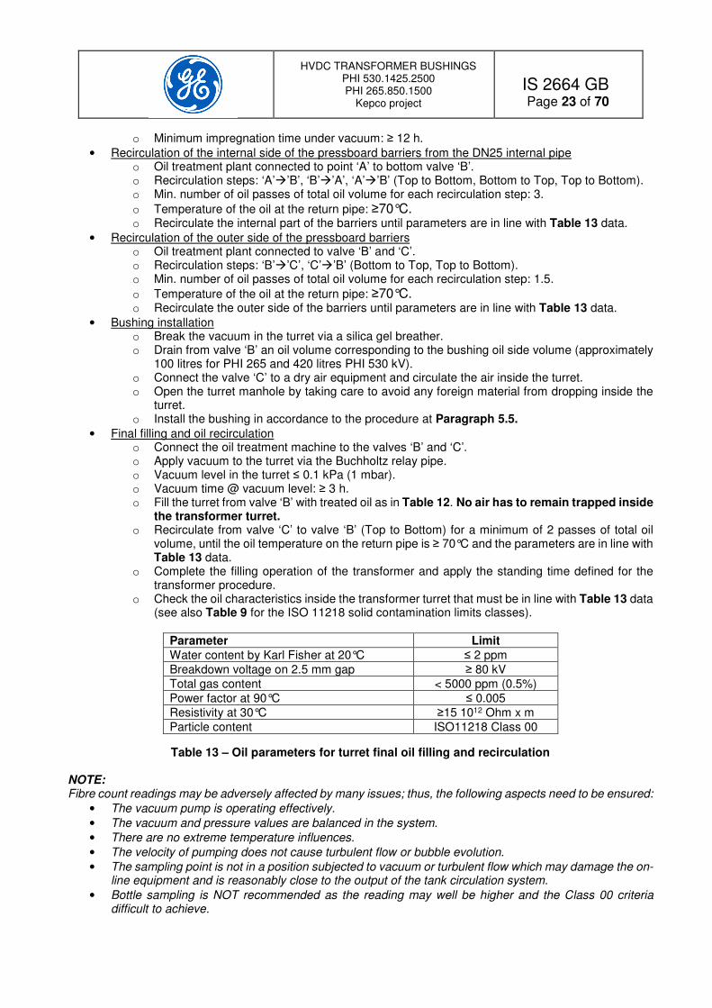
7 Transformer turret arrangement and oil parameters This chapter provides guidelines to the Transformer Manufacturer concerning the turret design and preparation of the turret oil processing procedure. Turret design and oil processing procedure are under the responsibility of the Transformer Manufacturer and the concepts illustrated in this part are not mandatory. Required is, in any case, the achievement of the parameters for the oil inside the pressboard barriers and the turret, listed in Table 13. The turret shall be designed to withstand the vacuum and it has to be provided with adequate valves to allow the proper bi-directional oil recirculation inside the barrier system. To perform this operation, it is suggested that a suitable DN 25 pipe will be welded on the top flange manhole. The length of this pipe should be sufficient to allow the injection of treated and filtered oil inside the pressboard barriers (see Figure 12).
Example of turret manhole with filtering pipe Example of internal DN 25 filtering pipe
Figure 12 – Example of turret manhole with internal DN 25 filtering pipe
Metal lid
By-pass valve
Metal lid By-pass valve
Filtering valves
¾” BSP connections
Protective caps
DN 25 internal pipe
A
Oil sampling valve

HVDC TRANSFORMER BUSHINGS PHI 530.1425.2500 PHI 265.850.1500
Kepco project
IS 2664 GB
Page 22 of 70
Next Figure 13 shows an example of turret arrangement during the treatment operation and relevant oil flows that can be realized by this arrangement.
Figure 13 – Transformer turret arrangement during filling and filtering operation The oil treatment plant to be used for the process should have the following characteristics:
• Be provided with 1µm filter with ceramic type cartridges. Paper type is not acceptable;
• able to recirculate under vacuum;
• sufficient heating power to ensure an oil temperature in the test tank ≥70°C;
• oil flow ≥ 4000 l/hour;
• possibility to reverse the oil flow in the turret without disconnecting the pipes. The recommended procedure includes the following steps:
• Vacuum in the turret o Apply vacuum to the turret via the transformer oil conservator and the Buchholtz relay pipe. o Vacuum level ≤ 0.1 kPa (1 mbar). o Vacuum time at vacuum level: ≥ 48 h.
• Oil filling under vacuum from bottom o Minimum oil filling characteristics as in Table 12. No air has to remain trapped inside the
transformer turret. At the end of the overall filling process, the air can be evacuated by the air draining plug located on the main flange of the PHI bushing below the oil expansion vessel (Prysmian type).
Parameter Limit Water content by Karl Fisher ≤ 3 ppm
Breakdown voltage on 2.5 mm gap > 70 kV
Particle content ISO11218 Class 0
Inlet oil temperature ≥70°C
Table 12 – Minimum oil filling parameters for turret filling
Top valve
Connection to the Buchholz relay
Oil Flow
Turret manhole
DN 25 filtering pipe
Bottom valve
Transformer turret
CT arrangement
PB barriers
HVDC transformer
lead
A
B
C
D Vacuum
HVDC TRANSFORMER BUSHINGS PHI 530.1425.2500 PHI 265.850.1500
Kepco project
IS 2664 GB
Page 23 of 70
o Minimum impregnation time under vacuum: ≥ 12 h.
• Recirculation of the internal side of the pressboard barriers from the DN25 internal pipe o Oil treatment plant connected to point ‘A’ to bottom valve ‘B’. o Recirculation steps: ‘A’’B’, ‘B’’A’, ‘A’’B’ (Top to Bottom, Bottom to Top, Top to Bottom). o Min. number of oil passes of total oil volume for each recirculation step: 3.
o Temperature of the oil at the return pipe: ≥70°C. o Recirculate the internal part of the barriers until parameters are in line with Table 13 data.
• Recirculation of the outer side of the pressboard barriers o Oil treatment plant connected to valve ‘B’ and ‘C’. o Recirculation steps: ‘B’’C’, ‘C’’B’ (Bottom to Top, Top to Bottom). o Min. number of oil passes of total oil volume for each recirculation step: 1.5.
o Temperature of the oil at the return pipe: ≥70°C. o Recirculate the outer side of the barriers until parameters are in line with Table 13 data.
• Bushing installation o Break the vacuum in the turret via a silica gel breather. o Drain from valve ‘B’ an oil volume corresponding to the bushing oil side volume (approximately
100 litres for PHI 265 and 420 litres PHI 530 kV). o Connect the valve ‘C’ to a dry air equipment and circulate the air inside the turret. o Open the turret manhole by taking care to avoid any foreign material from dropping inside the
turret. o Install the bushing in accordance to the procedure at Paragraph 5.5.
• Final filling and oil recirculation o Connect the oil treatment machine to the valves ‘B’ and ‘C’. o Apply vacuum to the turret via the Buchholtz relay pipe. o Vacuum level in the turret ≤ 0.1 kPa (1 mbar). o Vacuum time @ vacuum level: ≥ 3 h. o Fill the turret from valve ‘B’ with treated oil as in Table 12. No air has to remain trapped inside
the transformer turret. o Recirculate from valve ‘C’ to valve ‘B’ (Top to Bottom) for a minimum of 2 passes of total oil
volume, until the oil temperature on the return pipe is ≥ 70°C and the parameters are in line with Table 13 data.
o Complete the filling operation of the transformer and apply the standing time defined for the transformer procedure.
o Check the oil characteristics inside the transformer turret that must be in line with Table 13 data (see also Table 9 for the ISO 11218 solid contamination limits classes).
Parameter Limit Water content by Karl Fisher at 20°C ≤ 2 ppm
Breakdown voltage on 2.5 mm gap ≥ 80 kV
Total gas content < 5000 ppm (0.5%)
Power factor at 90°C ≤ 0.005
Resistivity at 30°C ≥15 1012 Ohm x m
Particle content ISO11218 Class 00
Table 13 – Oil parameters for turret final oil filling and recirculation NOTE: Fibre count readings may be adversely affected by many issues; thus, the following aspects need to be ensured:
• The vacuum pump is operating effectively.
• The vacuum and pressure values are balanced in the system.
• There are no extreme temperature influences.
• The velocity of pumping does not cause turbulent flow or bubble evolution.
• The sampling point is not in a position subjected to vacuum or turbulent flow which may damage the on-line equipment and is reasonably close to the output of the tank circulation system.
• Bottle sampling is NOT recommended as the reading may well be higher and the Class 00 criteria difficult to achieve.

HVDC TRANSFORMER BUSHINGS PHI 530.1425.2500 PHI 265.850.1500
Kepco project
IS 2664 GB
Page 24 of 70
8 Gas SF6 characteristics and gas filling instructions The SF6 gas to be used to fill the bushing must comply with the data shown in the following Table 14. This table shows the limits stated by GE Energy Connections RPV specification and the characteristics of a Premium Supplier:
Characteristics Unit GE Energy Connections RPV
limits
Premium Supplier’s limits
Min SF6 % by weight ≥99.9% ≥99.993%
Air ppm by weight ≤500 ppm w ≤50 ppm w
CF4 ppm by weight ≤500 ppm w ≤10 ppm w
H2O ppm by weight ≤15 ppm w ≤0.65 ppm w
Dew point @ atmospheric pressure °C ≤-40°C ≤-65°C
Mineral oil ppm by weight ≤10 ppm w ≤1 ppm w
Total acidity expressed in HF ppm by weight ≤0.3 ppm w ≤0.3 ppm w
Hydrolizable fluorides in terms of HF ppm by weight ≤1 ppm w ≤1 ppm w
Table 14 - Characteristics of new SF6 gas according GE Energy Connections RPV and premium Supplier
The minimum requirement is that the characteristics have to be in accordance with the data listed in the GE Energy Connections RPV limits column. Before proceeding with filling or re-filling operations the gas characteristics must be checked and the data must be reported in the Gas filling check list, see Appendix 8. The gas filling must be performed with an equipment that prevents dispersion of the SF6 gas in the atmosphere. As an example, next Figure 14 shows a gas plant manufactured by the German company DILO GmbH.
Figure 14 – Vacuum filling gas plant DILO NOTE: This bushing has to be operated with pure SF6. In case of need of replacement of SF6 gas with a mixture SF6 N2, before proceeding, please contact GE Energy Connections RPV for instructions and approval. WARNING: The following safety notes are mandatory.
• The bushing can be filled at the rated filling pressure of 0.63 MPa abs (5.3 bar gauge @ 20°C), only when installed on the transformer ready for the electrical tests or placed inside valve hall wall.
• If, for any reason, the bushing has to be removed from the transformer turret, it is mandatory to reduce the gas pressure to 0.125 MPa abs (0.25 bar gauge) before proceeding with the operation.
• If the transformer is stored with the bushings installed, the gas pressure must be reduced to 0.150 MPa abs (0.5 bar gauge) and periodically checked.
• All gas filling and gas recovering operations must be performed by a gas plant device (example a DILO machine).
WARNING: Before proceeding with the gas filling operation, remove the Transport pressure gauge (see Paragraph 3.1 and Figure 1).

HVDC TRANSFORMER BUSHINGS PHI 530.1425.2500 PHI 265.850.1500
Kepco project
IS 2664 GB
Page 25 of 70
8.1 Gas first filling operation and control of alarm and tripping signals The bushing is shipped in slight overpressure of SF6 gas. If the pressure is positive proceed with the operation as follows, on the contrary, contact GE Energy Connections Supervisor for additional instructions.
• Check that the Transport pressure gauge has been removed (see Figure 1).
• Check the gas characteristics and fill the data on the Gas filling check list, see Appendix 8.
• Connect the gas plant to the DILO filling valve on the bushing flange.
• Gradually increase the gas pressure up to 0.2 MPa abs (1 bar gauge). Pressure must be directly measured on the gas density monitors installed on the bushing flange.
• Check all the gas seals for leakages with a suitable SF6 leak-meter device. In case of significant leakages stop the activities and contact GE Energy Connections Supervisor.
• If the bushing does not show any leakage gradually increase the pressure at the rated filling pressure value of 0.63 MPa (5.3 bar gauge). The pressure must be directly measured on the compensated gas density monitors installed on the bushing flange.
• During the pressure rise, check the functionality of the Tripping (0.52 MPa abs), Alarm 2 (0.55 MPa abs) and Alarm 1 (0.58 MPa abs) contacts and record the respective operating pressures on the bushing check list, see Appendix 7. In case of malfunction, check the wiring and inform GE Energy Connections Supervisor.
• During the alarm / tripping functionality test, record on the bushing check list the readings on the two gas density monitors.
• Keep the bushing at the rated filling pressure for 4 hours, the purpose of this standing time is to allow the gas temperature stabilization, then make the final adjustment of the gas pressure.
• Disconnect the gas plant from the DILO filling valve located on the bushing flange. The gas density monitors installed on gas bushings are fully thermally compensated devices that indicate the pressure independently from the effective gas temperature. Whatever the temperature of the gas, the instrument indicates a pressure equivalent to a gas average temperature of 20°C. This condition is directly related to the gas density inside the bushing (see Chapter 10). 8.2 Gas refilling during the bushing normal operation The bushing is a fully sealed unit and its leakage rate is <0.5% x year. Anyway, after many years of operation it could be necessary to refill it. The refilling operation has to be done within 7 – 10 days after Alarm 1 intervention and it is mandatory to perform it within 1 – 2 days after the Alarm 2 intervention. Gas refilling can be done from the DILO type valve located on the bushing flange by a gas plant or a SF6 bottle, equipped with the appropriate pressure reduction equipment and DILO connecting plug (contact DILO GmbH for information about filling set equipment for direct bottle filling). The filling procedure is here below described:
• Check the gas characteristics and fill the data on the Gas filling check list, see Appendix 8.
• Connect the gas filling equipment (gas plant or SF6 system for direct filling from gas bottles) to the filling valve of the bushing flange.
• Gradually and slowly increase the gas pressure up to the rated filling pressure value of 0.63 MPa abs @20°C (5.3 bar gauge). Pressure must be directly measured on the temperature compensated pressure gauge installed on the bushing.
• Stop the gas filling equipment and shut the bottle valves.
• Disconnect the filling equipment from the gas filling station DILO valve. NOTE: In case of use of the DILO machine, check that the machine set-up is for gas filling and that the connecting pipe is full of SF6 before connecting to the gas filling station DILO valve. In case of direct filling from the bottle, check that the bottle is effectively charged with SF6, that the gas quantity is sufficient for the re-filling, the pressure reduction unit and the pipe are compatible with the DILO filling system and all equipment is specific for SF6 filling application and certified for a safe use. Also in this case, before connecting the equipment to the gas filling station, check that the connecting pipe is effectively filled by SF6 gas.

HVDC TRANSFORMER BUSHINGS PHI 530.1425.2500 PHI 265.850.1500
Kepco project
IS 2664 GB
Page 26 of 70
WARNING: The gas re-filling operation MUST be performed with the bushing de-energized and grounded. Safety prescriptions of Chapter 2 must be followed. WARNING: The refilling action must be performed by qualified operators. The risk is that a wrong operation can drain the gas from the bushing with possibility of plant tripping and equipment damages if the gas leakage will be excessive. WARNING: Always use equipment certified for SF6 gas. This will avoid mistakes, safety issues and risk for the environment and the equipment. 8.3 Gas characteristics before the energization Before the energization the gas parameters must be checked and, in particular:
Parameter Value
Gas Purity > 99.6 %
Gas Dew point @ rated filling pressure
< -20°C
SO2 Absent
Other pollutant As in Table 14
Table 15 – Gas parameters limits at the bushing energization
Gas data must be recorded on a check list.
9 Procedure for bushing gas compartment decontamination This part is applicable only in case of evidence of internal contamination by moisture. It is applicable to the following cases:
• SF6 transport pressure below the specified limits and / or with gas dew point ≥-30°C at atmospheric pressure.
• Evidence of gas dew point ≥ -20°C at rated filling pressure before the energization.
• Evidence of gas dew point ≥ -18°C at rated filling pressure during the normal operation.
• Opening of the bushing for internal inspection. Note: This procedure in not applicable in case of evidence of internal pollution by dust and other solid particles. This operation can be performed also with the bushing installed on the transformer. The procedure requires the use of dry Nitrogen with a dew point < -55°C. The operation is slightly different if the bushing is provided or not with the gas filling station. 9.1 Procedure for bushings equipped with the gas filling station
• Connect a digital pressure gauge to the DILO valve at the level of the bushing flange.
• Connect the DILO machine to the gas filling station DILO valve.
• Start the DILO machine, recover all the gas of the bushing and store it in clean gas bottles.
• Put the bushing under vacuum until the residual pressure measured at the bushing level will be <10 Pa abs (0.1 mbar abs).
• Keep the vacuum for at least 12 hours.
• Stop the pump and connect the Nitrogen bottle at the DILO valve placed on the gas filling station. The gas dew point must be < -55°C.
• Fill the bushing with dry Nitrogen at 0.25 MPa abs (1.5 bar gauge).

HVDC TRANSFORMER BUSHINGS PHI 530.1425.2500 PHI 265.850.1500
Kepco project
IS 2664 GB
Page 27 of 70
• Two hours after the completion of filling operation, measure the gas pressure and the dew point at atmospheric pressure and record the data.
• Repeat the same measurements after 24h and record the data.
• If the pressure loss is negligible and the dew point increase between the two measurements is less than 5°C proceed as follow:
o Remove all Nitrogen by putting the bushing under vacuum until the residual pressure measured at the bushing level will be <10 Pa abs (0.1 mbar abs).
o Keep the vacuum for at least 12 hours. o Proceed with the gas filling operation (see Chapter 8).
• If there is evidence of pressure drop it is necessary to investigate the problem with the support of a GE Energy Connections Specialist.
o If the pressure drop is negligible but the dew point variation is > 5°C, it is necessary to perform another cycle of vacuum and Nitrogen flushing.
9.2 Procedure for bushings not equipped with the gas filling station The procedure is the same as in Paragraph 9.1, except the fact that the equipment must be directly connected to the DILO valves located at the bushing flange.
10 Gas density monitor The bushing is equipped with two gas density monitors manufactured by Electronsystem The two instruments are different as one is a normal gas density monitor, while the other is equipped with an electronic pressure transducer 6-20 mA for remote indication (hybrid type). These devices ensure a great accuracy in the measurement, as they are based on the continuous and direct comparison between the gas density inside the bushing and the gas density of a built-in reference chamber filled with the same gas. This system is different and more accurate respect to the normal instruments that estimate the gas density through a pressure measurement corrected by a bimetal element that takes into account the ambient temperature. The next Figure 15 shows the instruments and its graduated scale.
Gas density monitor (example) Instrument scale
Figure 15 – Electronsystem gas density monitors The indication on the scale is expressed in MPa abs, referred to a gas temperature of 20°C. This means that the instrument converts the gas density into a value of pressure referred to 20°C, independently from the effective temperature of the gas. With this system, the instrument reading practically does not change with the gas temperature, that is a function of the bushing loading condition and ambient temperature.

HVDC TRANSFORMER BUSHINGS PHI 530.1425.2500 PHI 265.850.1500
Kepco project
IS 2664 GB
Page 28 of 70
Changing of reading during the bushing normal operation is an indication of gas leakages or malfunction of the instrument. Each gas monitoring device is equipped with three change-over micro switches that provide signals for alarm and tripping signals. Table 16 shows the micro switches purpose and the pressure set up (see Appendix 2 for the exact contacts arrangement of each gas monitoring device).
Micro switch Description Pressure set up
[MPa abs]
Alarm 1 Low pressure level 1 0.58
Alarm 2 Low pressure level 2
Minimum operating pressure 0.55
Tripping Too low pressure for operation 0.52
Table 16 – Alarm and tripping micro switches set-up
The instruments are installed on DILO valves for easy disassembly without the need to completely remove the gas from the bushing. In addition, the electrical cables of all devices are wired in a junction box provided with DIN type terminal blocks for easy assembly and maintenance (see Appendix 2). Additional information about the gas density monitor devices are illustrated in Appendix 4. NOTE: Due to the instrument principle of operation, the replacement of bushing gas from SF6 to a gas mixture SF6 N2 is not allowed without replacing the gas density monitors with the proper type. In this case contact GE Energy Connections RPV for support, instructions and approval. NOTE: The instrument equipped with the electronic sensor cannot be subject to the 2 kV 1’ on the terminals of the electronic sensor (terminals marked + - and relevant wiring at the junction box terminals X10 35 and 36) The application of such voltage to ground will cause an immediate failure of the instrument.
11 Power factor tap The bushing is equipped with one PF tap. This tap is used for capacitance, tan-delta and partial discharge measurements during the tests and in operation. In operation, it must be accurately closed with its screwed metal cap that ensures also the grounding connection.
Figure 16 – Power factor tap
Screwed cap
Clip type contact
PF tap insulator
Contact pin
HVDC TRANSFORMER BUSHINGS PHI 530.1425.2500 PHI 265.850.1500
Kepco project
IS 2664 GB
Page 29 of 70
To the PF tap it is possible to connect the voltage divider for the valve operation controlling system (see Chapter 12). WARNING: PF tap MUST be accurately closed with its cap or connected to the voltage divider unit. Missing the cap is dangerous and it will cause an electrical failure at bushing energizing.
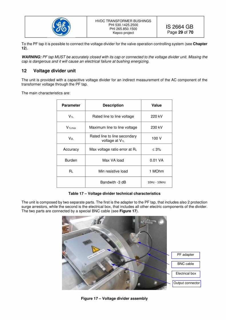
12 Voltage divider unit The unit is provided with a capacitive voltage divider for an indirect measurement of the AC component of the transformer voltage through the PF tap. The main characteristics are:
Parameter Description Value
V1L Rated line to line voltage 220 kV
V1Lmax Maximum line to line voltage 230 kV
V2L Rated line to line secondary
voltage at V1L 100 V
Accuracy Max voltage ratio error at RL ≤ 3%
Burden Max VA load 0.01 VA
RL Min resistive load 1 MOhm
Bandwith -3 dB 10Hz - 10kHz
Table 17 – Voltage divider technical characteristics The unit is composed by two separate parts. The first is the adapter to the PF tap, that includes also 2 protection surge arrestors, while the second is the electrical box, that includes all other electric components of the divider. The two parts are connected by a special BNC cable (see Figure 17).
Figure 17 – Voltage divider assembly
Electrical box
PF adapter
BNC cable
Output connector
HVDC TRANSFORMER BUSHINGS PHI 530.1425.2500 PHI 265.850.1500
Kepco project
IS 2664 GB
Page 30 of 70
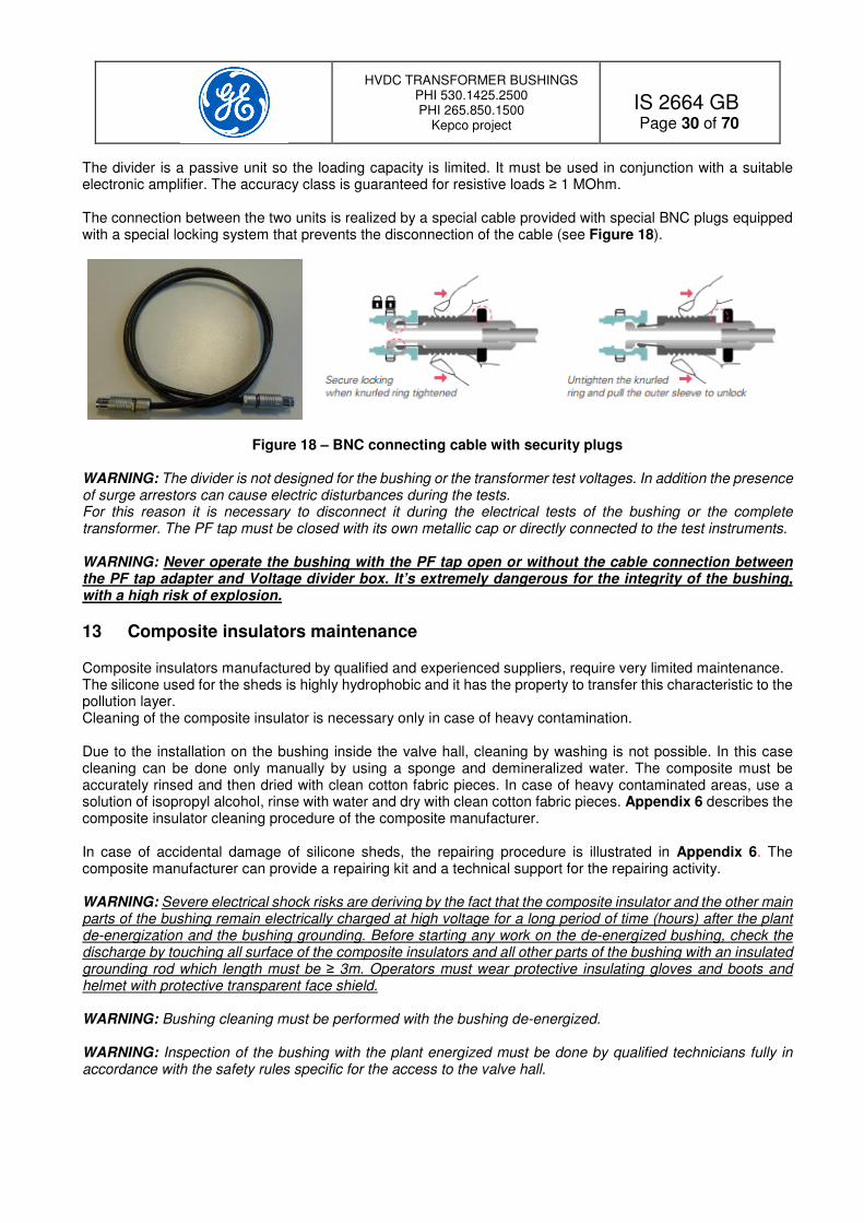
The divider is a passive unit so the loading capacity is limited. It must be used in conjunction with a suitable electronic amplifier. The accuracy class is guaranteed for resistive loads ≥ 1 MOhm. The connection between the two units is realized by a special cable provided with special BNC plugs equipped with a special locking system that prevents the disconnection of the cable (see Figure 18).
Figure 18 – BNC connecting cable with security plugs
WARNING: The divider is not designed for the bushing or the transformer test voltages. In addition the presence of surge arrestors can cause electric disturbances during the tests. For this reason it is necessary to disconnect it during the electrical tests of the bushing or the complete transformer. The PF tap must be closed with its own metallic cap or directly connected to the test instruments. WARNING: Never operate the bushing with the PF tap open or without the cable connection between the PF tap adapter and Voltage divider box. It’s extremely dangerous for the integrity of the bushing, with a high risk of explosion.
13 Composite insulators maintenance Composite insulators manufactured by qualified and experienced suppliers, require very limited maintenance. The silicone used for the sheds is highly hydrophobic and it has the property to transfer this characteristic to the pollution layer. Cleaning of the composite insulator is necessary only in case of heavy contamination. Due to the installation on the bushing inside the valve hall, cleaning by washing is not possible. In this case cleaning can be done only manually by using a sponge and demineralized water. The composite must be accurately rinsed and then dried with clean cotton fabric pieces. In case of heavy contaminated areas, use a solution of isopropyl alcohol, rinse with water and dry with clean cotton fabric pieces. Appendix 6 describes the composite insulator cleaning procedure of the composite manufacturer. In case of accidental damage of silicone sheds, the repairing procedure is illustrated in Appendix 6. The composite manufacturer can provide a repairing kit and a technical support for the repairing activity. WARNING: Severe electrical shock risks are deriving by the fact that the composite insulator and the other main parts of the bushing remain electrically charged at high voltage for a long period of time (hours) after the plant de-energization and the bushing grounding. Before starting any work on the de-energized bushing, check the discharge by touching all surface of the composite insulators and all other parts of the bushing with an insulated grounding rod which length must be ≥ 3m. Operators must wear protective insulating gloves and boots and helmet with protective transparent face shield. WARNING: Bushing cleaning must be performed with the bushing de-energized. WARNING: Inspection of the bushing with the plant energized must be done by qualified technicians fully in accordance with the safety rules specific for the access to the valve hall.
HVDC TRANSFORMER BUSHINGS PHI 530.1425.2500 PHI 265.850.1500
Kepco project
IS 2664 GB
Page 31 of 70
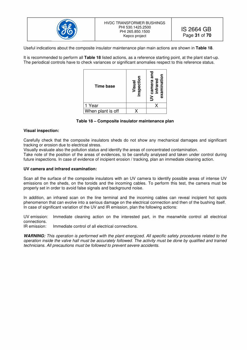
Useful indications about the composite insulator maintenance plan main actions are shown in Table 18. It is recommended to perform all Table 18 listed actions, as a reference starting point, at the plant start-up. The periodical controls have to check variances or significant anomalies respect to this reference status.
Time base
Vis
ua
l in
sp
ecti
on
UV
cam
era
an
d
infr
are
d
exam
inati
on
1 Year X When plant is off X
Table 18 – Composite insulator maintenance plan
Visual inspection: Carefully check that the composite insulators sheds do not show any mechanical damages and significant tracking or erosion due to electrical stress. Visually evaluate also the pollution status and identify the areas of concentrated contamination. Take note of the position of the areas of evidences, to be carefully analysed and taken under control during future inspections. In case of evidence of incipient erosion / tracking, plan an immediate cleaning action. UV camera and infrared examination: Scan all the surface of the composite insulators with an UV camera to identify possible areas of intense UV emissions on the sheds, on the toroids and the incoming cables. To perform this test, the camera must be properly set in order to avoid false signals and background noise. In addition, an infrared scan on the line terminal and the incoming cables can reveal incipient hot spots phenomenon that can evolve into a serious damage on the electrical connection and then of the bushing itself. In case of significant variation of the UV and IR emission, plan the following actions: UV emission: Immediate cleaning action on the interested part, in the meanwhile control all electrical connections. IR emission: Immediate control of all electrical connections. WARNING: This operation is performed with the plant energized. All specific safety procedures related to the operation inside the valve hall must be accurately followed. The activity must be done by qualified and trained technicians. All precautions must be followed to prevent severe accidents.

HVDC TRANSFORMER BUSHINGS PHI 530.1425.2500 PHI 265.850.1500
Kepco project
IS 2664 GB
Page 32 of 70
14 General maintenance plan The general maintenance plan is described in the next Table 19.
Component Time base Description Notes
Composite insulators See Chapter 13 Inspection and maintenance See Chapter 13
Gas SF6 When plant is off
Check the pressure and the operation of the density monitors, check the gas quality and the gas dew point.
Visual control of pressure at bushing density meters. Measure the gas purity and gas dew point.
Bushing oil When plant is off Check the pressure Control if the pressure is in line with the diagram of Figure 8.
Oil leakages When plant is off
Check for the presence of oil leakages from the bushing flange, along the oil pipe and on the relevant fitting and expansion vessels
Contact GE Energy Connections RPV in case of evidence of oil leakages from the bushing parts or accessories.
Toroids When plant is off Clean the surface and check for scratches or deformation. Check the fixing bolts to the flanges.
Anticipate the controls if UV camera reveals corona inception.
Current terminals When plant is off
Check for evidence of hot spots. Check the terminals and tighten the connecting bolts to the bushing flange. Check the cable clamps and the bolting to the terminal.
Anticipate the controls if IR camera reveals hot spots. Contact GE Energy Connections RPV in case of evidence of hot spots during the inspection.
Grounding terminals on the bushing flange
When plant is off
Check for evidence of hot spots. Check the connection integrity and the bolt locking. Verify the effectiveness of the grounding.
Contact GE Energy Connections RPV in case of evidence of hot spots.
Power factors taps (only if the bushing is not equipped with the voltage divider)
When plant is off
Remove the tap cap and clean inside. Check the internal spring-loaded contact and clean it. Perform a Megger 1 kV insulation test Rins > 1 MOhm. Carefully close and tighten the cap.
WARNING: PF tap cap MUST be accurately closed. Missing the cap could be dangerous and it can cause an electrical discharge at bushing energization.
Voltage divider When plant is off
Check that the PF adapter, the BNC cable and the divider box does not show any evidence of electrical discharge. Control the status of the components and the electrical connections inside the box.
Contact GE Energy Connections RPV in case of evidence of problems.

HVDC TRANSFORMER BUSHINGS PHI 530.1425.2500 PHI 265.850.1500
Kepco project
IS 2664 GB
Page 33 of 70
Component Time base Description Notes
Bushing oil Every 2 years, when the plant is off
Perform an oil DGA in accordance to IEC 61464.
Contact GE Energy Connections RPV in case of evidence of problems and provide all DGA data.
Gas density monitors and oil pressure gauge
5 years Check calibration and operation of micro switches.
Check the effective and correct operation of the alarms & tripping signal chain from the instruments to the substation systems.
Bushing overall gas leakage
5 years Check with SF6 leak-meter device all the flanges joints and the DILO valves.
Anticipate the control if the leakage rate is excessive and gas re-filling is frequent. Identify the leakage areas. In case of frequent re-filling, plan for the replacement of the bushing and contact GE Energy Connections RPV.
Gas quality 5 years Check the gas dew point at line pressure
Regenerate / replace the gas if moisture exceeds the limits of dew point ≥-18°C at line pressure.
Table 19 – Bushing general maintenance plan

HVDC TRANSFORMER BUSHINGS PHI 530.1425.2500 PHI 265.850.1500
Kepco project
IS 2664 GB
Page 34 of 70
15 Disposal at the end of life At the end of the bushing operative life all parts can be recycled or disposed as follows:
Part Material Action SF6 gas SF6 Remove by DILO machine, recycle or thermo-
destruction Bushing oil Mineral Oil Remove and recycle or thermo-destruction Grading capacitor Oil impregnated paper
and aluminum foils and tube
Dispose or thermo-destruction
Main central flanges Aluminum Dismount and recycle.
Central conductors Aluminum Dismount and recycle Top flange Aluminum Dismount and recycle Top electric terminals Copper silvered Dismount and recycle
Toroids Aluminum Dismount and recycle Internal electrostatic shields Aluminum Dismount and recycle
SF6 and oil side cones Fibreglass Dismount and dispose Aluminum Recycle the aluminum
Composite insulators with flanges Fibreglass Dispose or thermo-destruction Silicone Dispose or thermo-destruction Aluminum Dismount and recycle
Electrical wiring Aluminum Recycle Copper Recycle
Plastic Dispose or thermo-destruction Galvanized steel Recycle
DILO valves Aluminium or stainless steel
Recycle
Oil expansion vessels Steel Recycle Oil expansion vessel supports, piping and valves
Stainless steel Recycle
Gas density monitors and oil pressure gauges
Various Dispose or recycle as electronic products
Gaskets EPDM rubber, Viton Recycle or dispose or thermo-destruction
Table 20 – Bushing end of life management

HVDC TRANSFORMER BUSHINGS PHI 530.1425.2500 PHI 265.850.1500
Kepco project
IS 2664 GB
Page 35 of 70
List of appendices Appendix 1 – Bushing outline drawing. Appendix 2 – Electrical scheme. Appendix 3 – Lifting tools. Appendix 4 – Gas density monitor Electronsystem. Appendix 5 – Oil pressure gauge Appendix 6 – Composite insulators maintenance and repairing. Appendix 7 - Bushing installation check list. Appendix 8 – Filling gas check list.
HVDC TRANSFORMER BUSHINGS PHI 530.1425.2500 PHI 265.850.1500
Kepco project
IS 2664 GB
Page 36 of 70
PHI 265kV 1500A
Appendix 1 – Bushing outline drawing

HVDC TRANSFORMER BUSHINGS PHI 530.1425.2500 PHI 265.850.1500
Kepco project
IS 2664 GB
Page 37 of 70
PHI 530kV 2500A

HVDC TRANSFORMER BUSHINGS PHI 530.1425.2500 PHI 265.850.1500
Kepco project
IS 2664 GB
Page 38 of 70
PHI 265kV 1500A
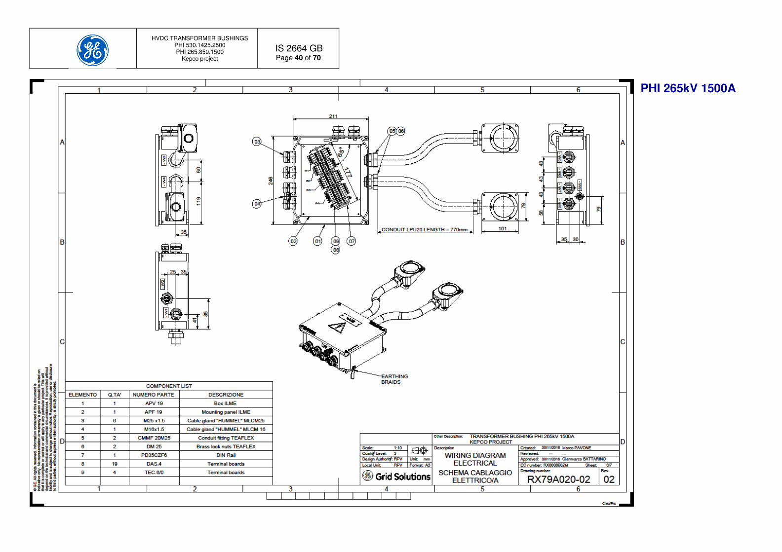
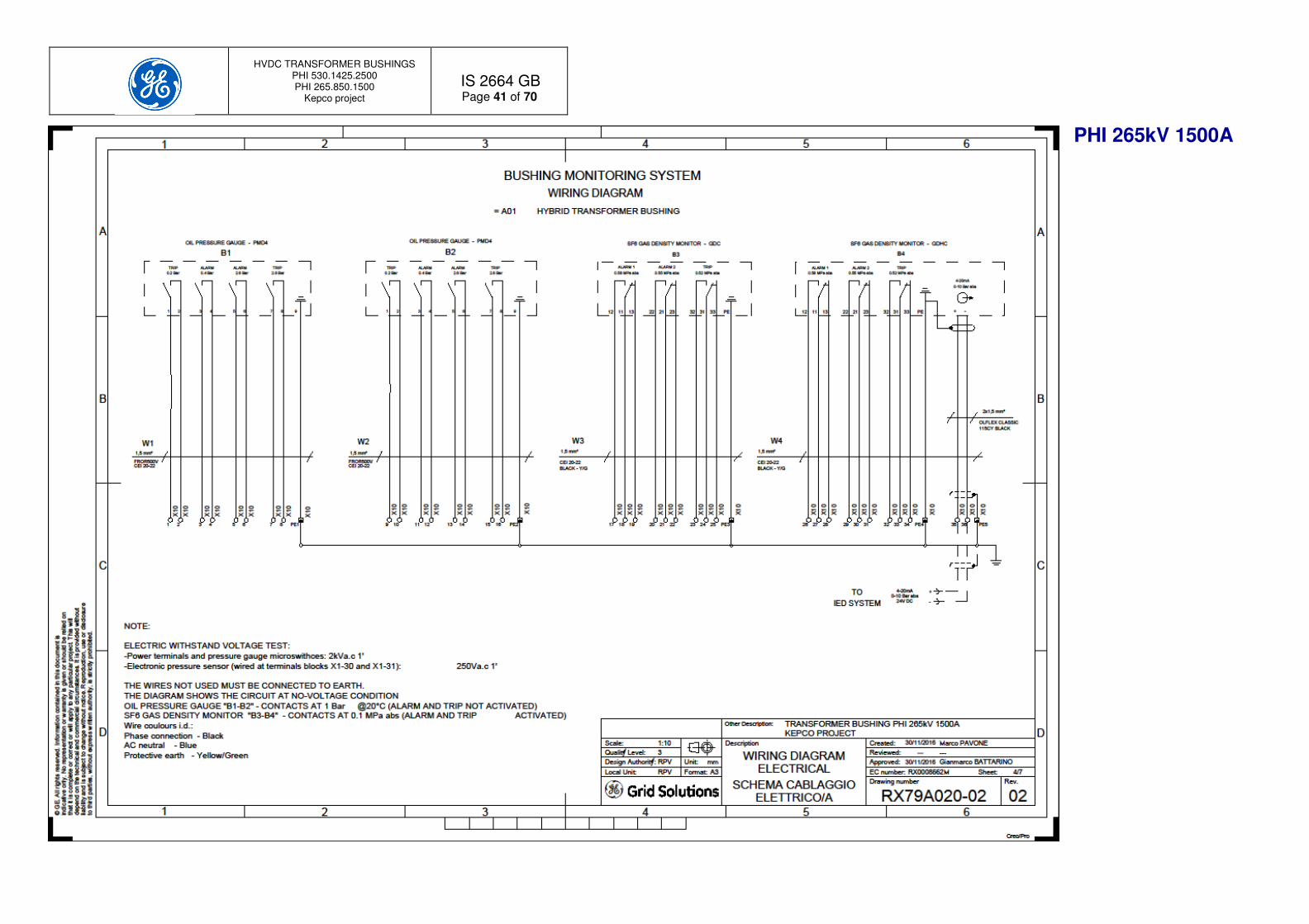
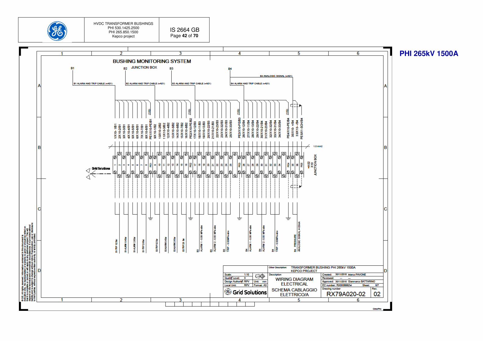
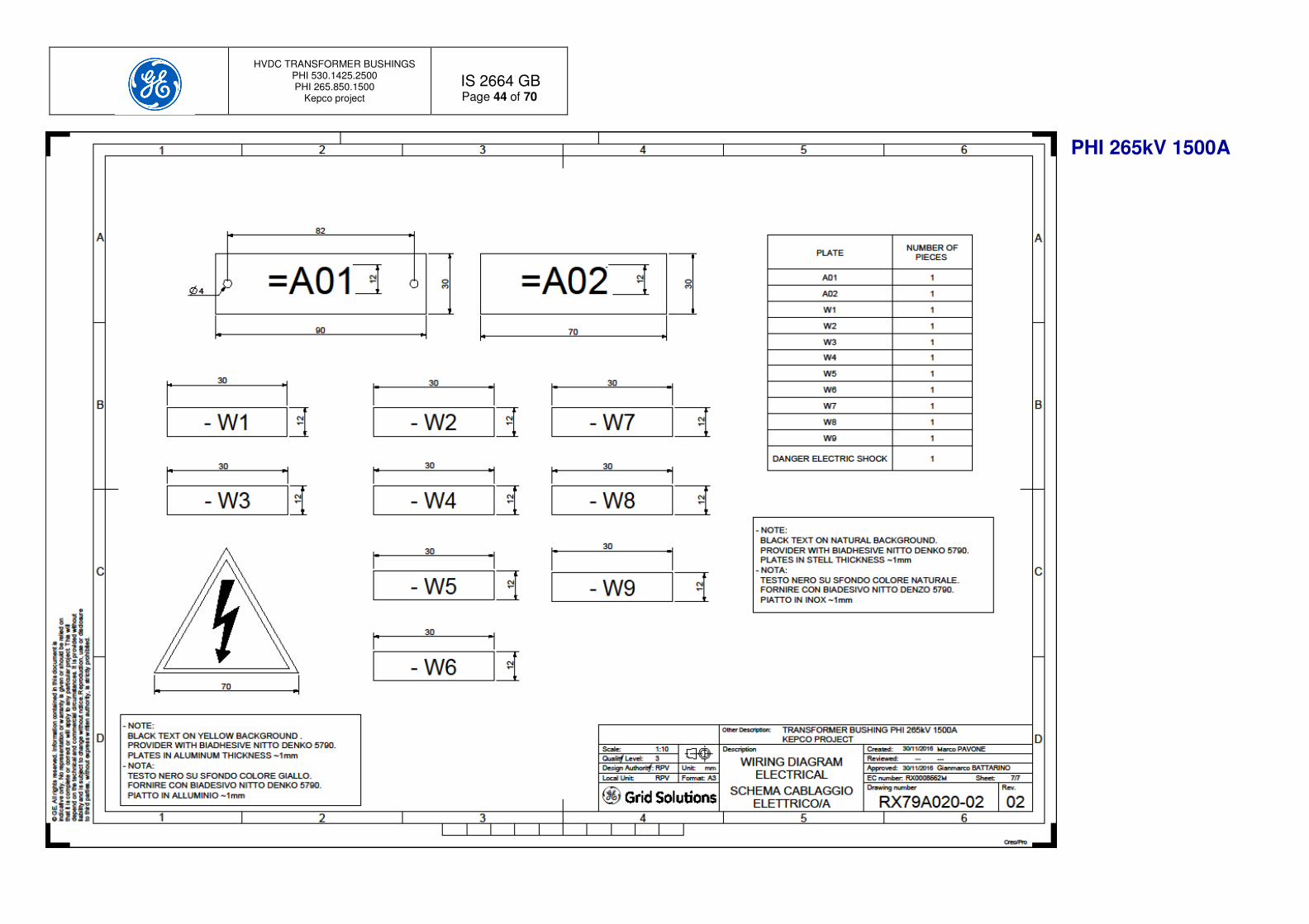
Appendix 2 – Electrical scheme

HVDC TRANSFORMER BUSHINGS PHI 530.1425.2500 PHI 265.850.1500
Kepco project
IS 2664 GB
Page 39 of 70
PHI 265kV 1500A
HVDC TRANSFORMER BUSHINGS PHI 530.1425.2500 PHI 265.850.1500
Kepco project
IS 2664 GB
Page 40 of 70
PHI 265kV 1500A
HVDC TRANSFORMER BUSHINGS PHI 530.1425.2500 PHI 265.850.1500
Kepco project
IS 2664 GB
Page 41 of 70
PHI 265kV 1500A
HVDC TRANSFORMER BUSHINGS PHI 530.1425.2500 PHI 265.850.1500
Kepco project
IS 2664 GB
Page 42 of 70
PHI 265kV 1500A

HVDC TRANSFORMER BUSHINGS PHI 530.1425.2500 PHI 265.850.1500
Kepco project
IS 2664 GB
Page 43 of 70
PHI 265kV 1500A
HVDC TRANSFORMER BUSHINGS PHI 530.1425.2500 PHI 265.850.1500
Kepco project
IS 2664 GB
Page 44 of 70
PHI 265kV 1500A

HVDC TRANSFORMER BUSHINGS PHI 530.1425.2500 PHI 265.850.1500
Kepco project
IS 2664 GB
Page 45 of 70
PHI 530kV 2500A

HVDC TRANSFORMER BUSHINGS PHI 530.1425.2500 PHI 265.850.1500
Kepco project
IS 2664 GB
Page 46 of 70
PHI 530kV 2500A
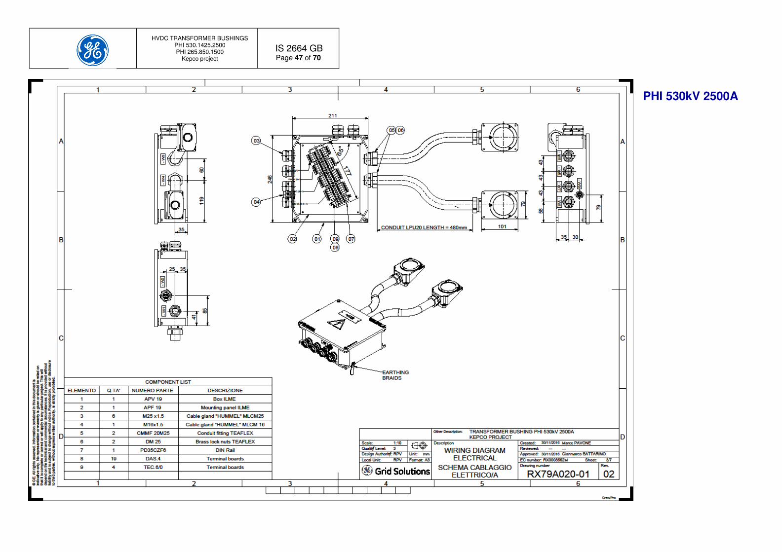
HVDC TRANSFORMER BUSHINGS PHI 530.1425.2500 PHI 265.850.1500
Kepco project
IS 2664 GB
Page 47 of 70
PHI 530kV 2500A

HVDC TRANSFORMER BUSHINGS PHI 530.1425.2500 PHI 265.850.1500
Kepco project
IS 2664 GB
Page 48 of 70
PHI 530kV 2500A

HVDC TRANSFORMER BUSHINGS PHI 530.1425.2500 PHI 265.850.1500
Kepco project
IS 2664 GB
Page 49 of 70
PHI 530kV 2500A
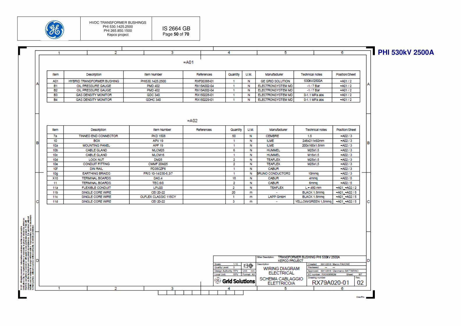
HVDC TRANSFORMER BUSHINGS PHI 530.1425.2500 PHI 265.850.1500
Kepco project
IS 2664 GB
Page 50 of 70
PHI 530kV 2500A

HVDC TRANSFORMER BUSHINGS PHI 530.1425.2500 PHI 265.850.1500
Kepco project
IS 2664 GB
Page 51 of 70
PHI 530kV 2500A
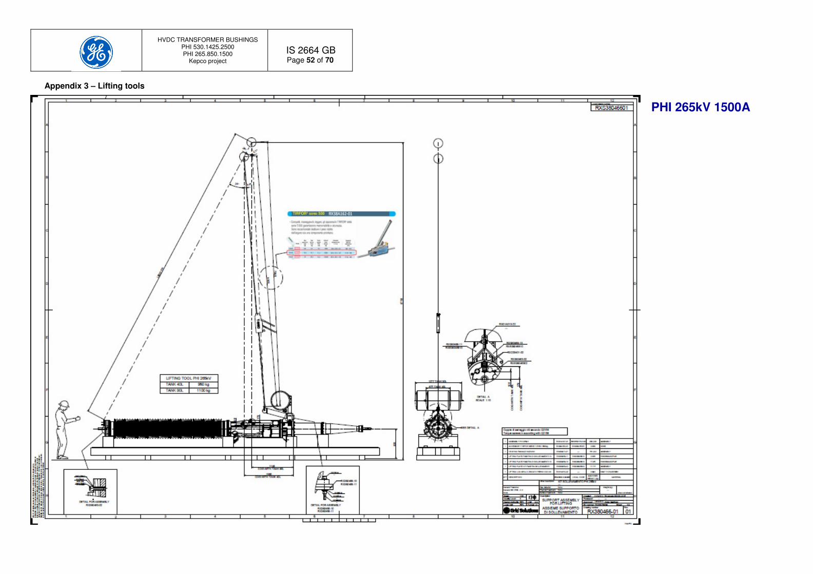
HVDC TRANSFORMER BUSHINGS PHI 530.1425.2500 PHI 265.850.1500
Kepco project
IS 2664 GB
Page 52 of 70
PHI 265kV 1500A
Appendix 3 – Lifting tools

HVDC TRANSFORMER BUSHINGS PHI 530.1425.2500 PHI 265.850.1500
Kepco project
IS 2664 GB
Page 53 of 70
PHI 265kV 1500A

HVDC TRANSFORMER BUSHINGS PHI 530.1425.2500 PHI 265.850.1500
Kepco project
IS 2664 GB
Page 54 of 70
PHI 265kV 1500A

HVDC TRANSFORMER BUSHINGS PHI 530.1425.2500 PHI 265.850.1500
Kepco project
IS 2664 GB
Page 55 of 70
PHI 265kV 1500A

HVDC TRANSFORMER BUSHINGS PHI 530.1425.2500 PHI 265.850.1500
Kepco project
IS 2664 GB
Page 56 of 70
PHI 530kV 2500A

HVDC TRANSFORMER BUSHINGS PHI 530.1425.2500 PHI 265.850.1500
Kepco project
IS 2664 GB
Page 57 of 70
PHI 530kV 2500A

HVDC TRANSFORMER BUSHINGS PHI 530.1425.2500 PHI 265.850.1500
Kepco project
IS 2664 GB
Page 58 of 70
PHI 530kV 2500A

HVDC TRANSFORMER BUSHINGS PHI 530.1425.2500 PHI 265.850.1500
Kepco project
IS 2664 GB
Page 59 of 70
PHI 530kV 2500A

HVDC TRANSFORMER BUSHINGS PHI 530.1425.2500 PHI 265.850.1500
Kepco project
IS 2664 GB
Page 60 of 70
Appendix 4 – Gas density monitor Electronsystem

HVDC TRANSFORMER BUSHINGS PHI 530.1425.2500 PHI 265.850.1500
Kepco project
IS 2664 GB
Page 61 of 70

HVDC TRANSFORMER BUSHINGS PHI 530.1425.2500 PHI 265.850.1500
Kepco project
IS 2664 GB
Page 62 of 70

HVDC TRANSFORMER BUSHINGS PHI 530.1425.2500 PHI 265.850.1500
Kepco project
IS 2664 GB
Page 63 of 70

HVDC TRANSFORMER BUSHINGS PHI 530.1425.2500 PHI 265.850.1500
Kepco project
IS 2664 GB
Page 64 of 70

HVDC TRANSFORMER BUSHINGS PHI 530.1425.2500 PHI 265.850.1500
Kepco project
IS 2664 GB
Page 65 of 70
Appendix 5 – Oil pressure gauge
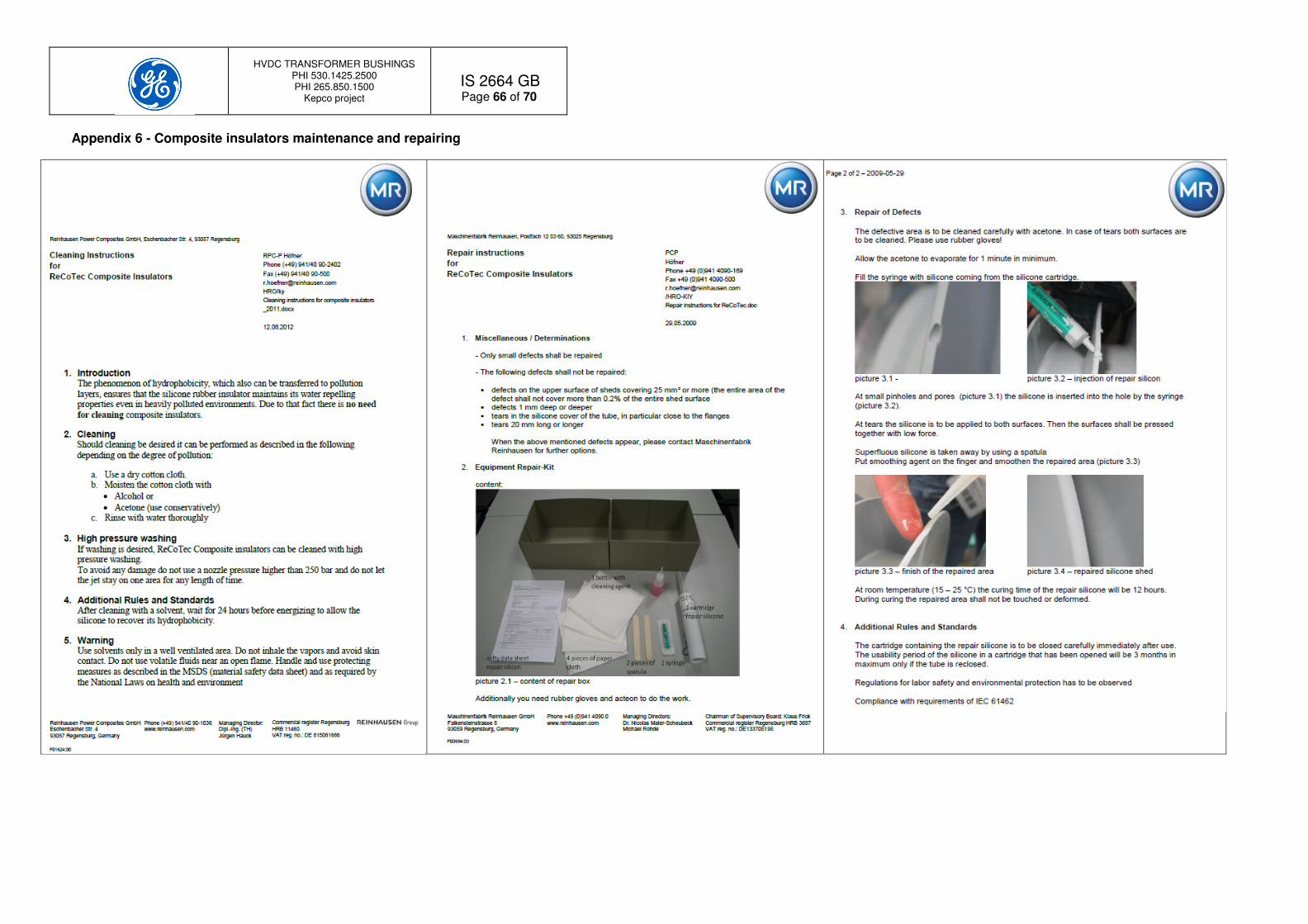
HVDC TRANSFORMER BUSHINGS PHI 530.1425.2500 PHI 265.850.1500
Kepco project
IS 2664 GB
Page 66 of 70
Appendix 6 - Composite insulators maintenance and repairing

HVDC TRANSFORMER BUSHINGS PHI 530.1425.2500 PHI 265.850.1500
Kepco project
IS 2664 GB
Page 67 of 70
Appendix 7 – Bushing installation check list
Bushing type:__________________________________________________________
Bushing Serial Number:__________________________________________________
Substation:____________________________________________________________
Date Prepared Checked
Item Description Activity Limits / recording Action on problems Date Signature
1 Controls at the arrival
Check the wooden crate status. No great damages outside. Take pictures and inform GE Energy Connections RPV
Check the external visual impact recorder(s). No intervention of the devices. Take pictures and inform GE Energy Connections RPV
Open the crate and inspect packaging and goods inside. No visible damages on goods. Take pictures and inform GE Energy Connections RPV
Check the pressure of the gas inside the bushing and the gas Dew point.
Check gas pressure:
0.11 MPa abs ≤ Gas pressure ≤0.125 MPa abs
(0.1 bar gauge ≤ Gas pressure ≤0.25 bar gauge) Dew point ≥-30°C at atmospheric pressure
Contact GE Energy Connections RPV
Check that the oil pressure is ≥1 bar @20°C, record the bushing avg. temperature Verify the absence of oil leakages from the bushing.
Pressure and temperature recording
At oil gauge: _________ bar gauge
tavg: _________ °C
In case of pressure not in line wth the
diagram pressure / temperature Figure 8 or evidence of oil leakages contact GE Energy Connections RPV
Check the composite insulator status, the top terminal and the relevant accessories. No damages. Take pictures and inform GE Energy Connections RPV
Check the oil side cone, the contact springs and the relevant accessories No scratches No damages
Contact GE Energy Connections RPV
Check the bushing instruments and the status of the electric wiring. Check the status of the oil valves and the warranty seals
No damages. Contact GE Energy Connections RPV.
2 Electronic Impact recorder (if installed) Remove the impact recorder and ship it to GE Energy Connections RPV. Only for bushings shipped with the electronic impact recorder
---
3 Transformer turret treatment data Check that the transformer turret has been processed in accordance with the Transformer Manufacturer procedure and that oil parameters inside the barriers are in line with Table 13 data.
Oil final characteristics: Water content by KF at 20°C: ________ ppm Breakdown voltage on 2.5 mm gap: ___ kV Total gas content: _________________ ppm Power factor at 90°C: ______________
Resistivity at 30°C: ________________ Ω x m Particle content ISO class: __________
If parameters are not OK stop bushing installation activities and proceed with a new treatment of the transformer turret. Inform GE Energy Connections RPV.
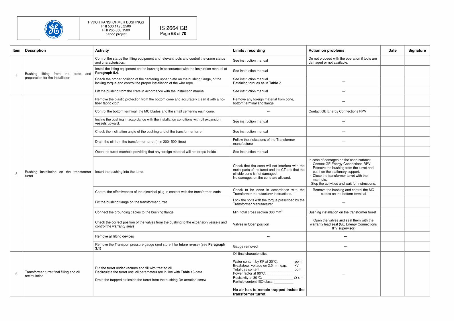
HVDC TRANSFORMER BUSHINGS PHI 530.1425.2500 PHI 265.850.1500
Kepco project
IS 2664 GB
Page 68 of 70
Item Description Activity Limits / recording Action on problems Date Signature
4 Bushing lifting from the crate and preparation for the installation
Control the status the lifting equipment and relevant tools and control the crane status and characteristics.
See instruction manual Do not proceed with the operation if tools are damaged or not available.
Install the lifting equipment on the bushing in accordance with the instruction manual at Paragraph 5.4.
See instruction manual ---
Check the proper position of the centering upper plate on the bushing flange, of the locking torque and control the proper installation of the wire rope.
See instruction manual Retaining torques as in Table 7
---
Lift the bushing from the crate in accordance with the instruction manual. See instruction manual ---
5 Bushing installation on the transformer turret
Remove the plastic protection from the bottom cone and accurately clean it with a no-fiber fabric cloth.
Remove any foreign material from cone, bottom terminal and flange
---
Control the bottom terminal, the MC blades and the small centering resin cone. --- Contact GE Energy Connections RPV
Incline the bushing in accordance with the installation conditions with oil expansion vessels upward.
See instruction manual ---
Check the inclination angle of the bushing and of the transformer turret See instruction manual ---
Drain the oil from the transformer turret (min 200- 500 litres) Follow the indications of the Transformer manufacturer
---
Open the turret manhole providing that any foreign material will not drops inside See instruction manual ---
Insert the bushing into the turret
Check that the cone will not interfere with the metal parts of the turret and the CT and that the oil side cone is not damaged. No damages on the cone are allowed.
In case of damages on the cone surface: - Contact GE Energy Connections RPV. - Remove the bushing from the turret and
put it on the stationary support. - Close the transformer turret with the
manhole. Stop the activities and wait for instructions.
Control the effectiveness of the electrical plug-in contact with the transformer leads Check to be done in accordance with the Transformer manufacturer instructions.
Remove the bushing and control the MC blades on the bottom terminal
Fix the bushing flange on the transformer turret Lock the bolts with the torque prescribed by the Transformer Manufacturer
---
Connect the grounding cables to the bushing flange Min. total cross section 300 mm2 Bushing installation on the transformer turret
Check the correct position of the valves from the bushing to the expansion vessels and control the warranty seals
Valves in Open position Open the valves and seal them with the
warranty lead seal (GE Energy Connections RPV supervisor).
Remove all lifting devices --- ---
Remove the Transport pressure gauge (and store it for future re-use) (see Paragraph 3.1)
Gauge removed ---
6 Transformer turret final filling and oil recirculation
Put the turret under vacuum and fill with treated oil. Recirculate the turret until oil parameters are in line with Table 13 data. Drain the trapped air inside the turret from the bushing De-aeration screw
Oil final characteristics: Water content by KF at 20°C: ________ ppm Breakdown voltage on 2.5 mm gap: ___ kV Total gas content: _________________ ppm Power factor at 90°C: ______________
Resistivity at 30°C: ________________ Ω x m Particle content ISO class: __________
No air has to remain trapped inside the transformer turret.
---

HVDC TRANSFORMER BUSHINGS PHI 530.1425.2500 PHI 265.850.1500
Kepco project
IS 2664 GB
Page 69 of 70
Item Description Activity Limits / recording Action on problems Date Signature
7 Gas filling
Check that the Transport pressure gauge has been removed and properly stored for future use)
See instruction manual Remove the Transport pressure gauge before filling the bushing.
Check the filling gas parameters of the bottles from gas certificates and by quality tests performed on the single bottle
Fill the Gas Check list Do not fill with gas if gas is not OK.
Connect the gas hose to the bushing DILO type valve. See instruction manual ---
Start filling operation. Stop at 0.2 MPa abs (1 bar gauge) ---
Check for leakage with the gas leak-meter device. Check all bushing flanges and connections and also all the gas filling station (if included)
Contact GE Energy Connections RPV.
Increase the gas pressure until the Tripping contacts operates (0.52 MPa abs). Check the remote reading of the gas pressure sensor
Gas pressure (B3/B4)=______/_____MPa abs Remote pressure: ________________MPa bs
NO OK: 1) Check the wiring. 2) Reduce the gas pressure and repeat the
full test sequence. 3) Inform GE Energy Connections RPV
Increase the gas pressure until Alarm 2 contact operates (0.55 MPa abs). Check the remote reading of the gas pressure sensor
Gas pressure (B3/B4)=______/_____MPa abs Remote pressure: ________________MPa bs
Increase the gas pressure until Alarm 1 contact operates (0.58 MPa abs). Check the remote reading of the gas pressure sensor
Gas pressure (B3/B4)=______/_____MPa abs Remote pressure: ________________MPa bs
Increase the gas pressure at the rated filling value (0.63 MPa). Wait 4 hours stabilize and record the pressure values.
Pressure recording
At gas monitor B3: ____________ MPa abs
At gas monitor B4: ____________ MPa abs
Remote pressure: ________________MPa bs
---
Perform a gas analyses and a gas Dew Point 48 h after the gas filling operation
Gas data recording (see Table 15)
Filling pressure: ____________ MPa abs
Gas Purity: ____________ %SF6
SO2: ____________ ppm w
Dew point @ Filling pressure:______ °C
Contact GE Energy Connections RPV
8 Check PF tap and voltage divider Check that the PF tap is firmly closed or that the adapter is installed and wired to the divider unit.
See instruction manual Do not energize the bushing if the PF tap cap is missing or if the tap is not connected to the voltage divider unit
---
9 Remove composite insulator plastic foils Remove all plastic protective foils from both composite insulators when the bushing is installed and the transformer is inside the valve room.
--- ---
10 Top shield installation Install the top shield bushing when the transformer is inside the valve room. ---

HVDC TRANSFORMER BUSHINGS PHI 530.1425.2500 PHI 265.850.1500
Kepco project
IS 2664 GB
Page 70 of 70
Appendix 8 – Gas filling check list
ppm by weight from gas certificates
ppm by weight from measurements
Bottle S.N.
Bushing S.N. SF6 content by weight
Air CF4 H2O Mineral oil Total acidity expressed in
HF
Hydrolizable fluorides in
terms of HF
Dew point at amospheric
pressure
SF6 content by weight
HF SO2
Reference data ≥99.9% ≤≤≤≤500 ppmw ≤≤≤≤500 ppmw ≤≤≤≤15 ppmw ≤≤≤≤10 ppmw ≤≤≤≤0.3 ppmw ≤≤≤≤1 ppmw ≤≤≤≤ -40°C ≥99.9% ≤≤≤≤1 ppmw ≤≤≤≤0 ppmw
Date:
Prepared by:
Controlled by: