Embed Size (px)
Citation preview

HVDC links in AC power system
Pierre Bornard
Deputy CEO | RTE

New challenges & drivers
❷
HVDC fundamentals
INELFE example
HVDC integration / issues
HVDC integration / R&D role
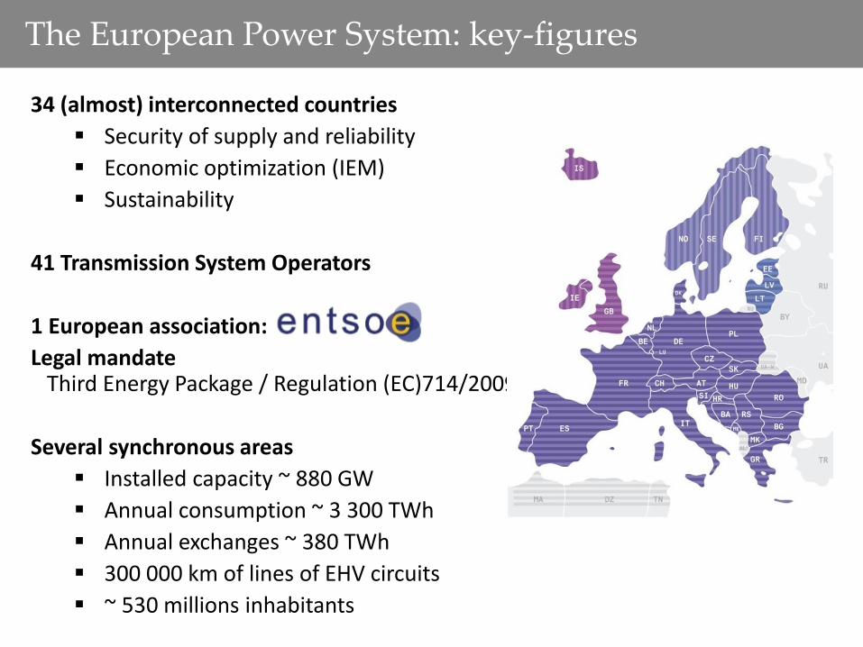
The European Power System: key-figures
34 (almost) interconnected countries
Security of supply and reliability
Economic optimization (IEM)
Sustainability
41 Transmission System Operators
1 European association:
Legal mandate Third Energy Package / Regulation (EC)714/2009
Several synchronous areas
Installed capacity ~ 880 GW
Annual consumption ~ 3 300 TWh
Annual exchanges ~ 380 TWh
300 000 km of lines of EHV circuits
~ 530 millions inhabitants

Today European grid: the engineer’s map

Tomorrow European supergrid: the poet’s map
Source: FOSG

NEW CHALLENGES & DRIVERS
Source: Marc Didier

The 2030 EU Council targets
About 45% of RES generation in
the electricity transmission system
+27% energy efficiency
-40% CO2 emissions
27% Renewable
Energy Sources
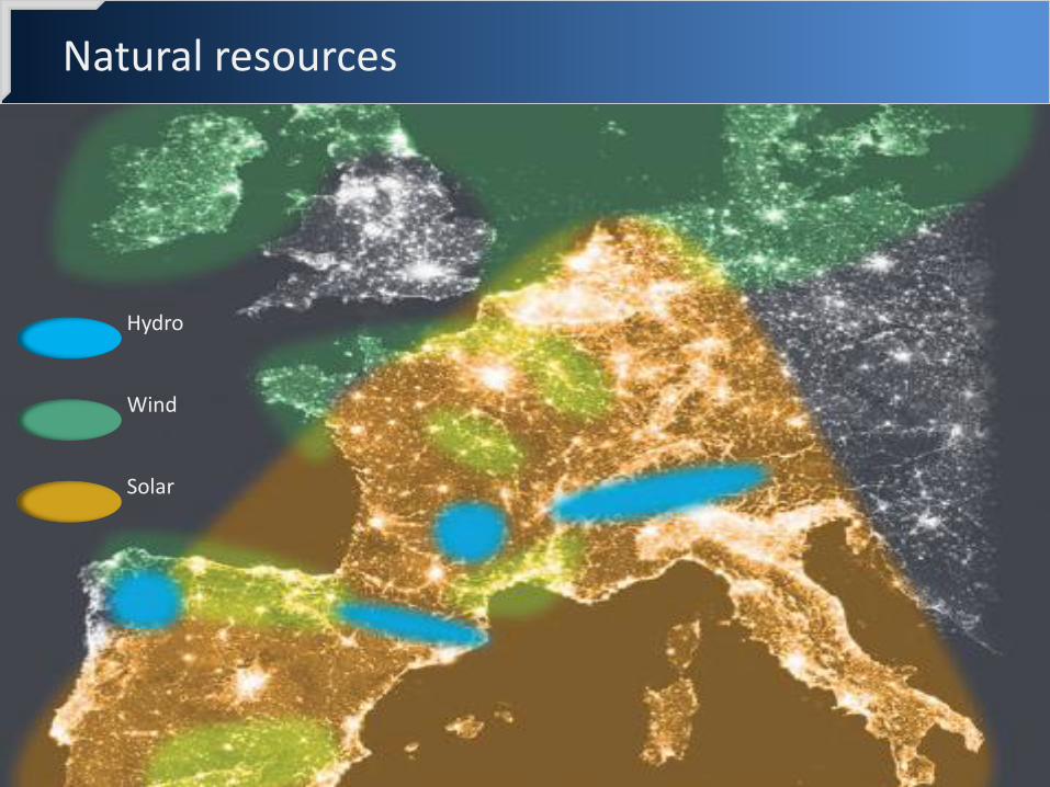
Natural resources
Hydro
Wind
Solar

Wind power expansion
Wind share of demand: 2010 → 5% 2020 → 23% 2030 → 36%
Source : EWEA 2011

RES boom in Germany
10
2000 2010
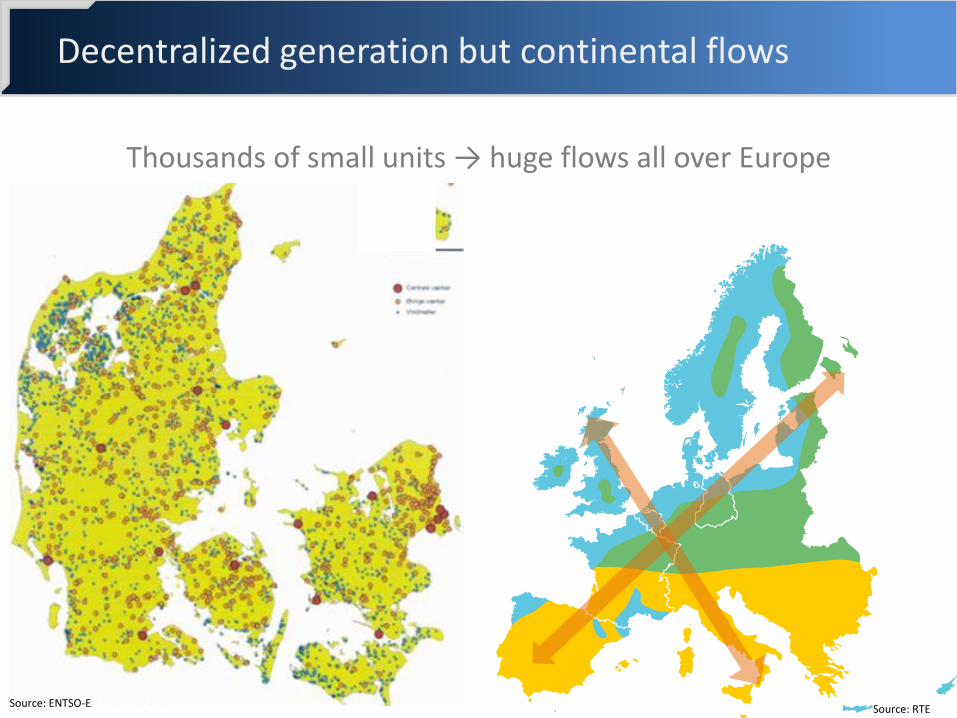
Decentralized generation but continental flows
Thousands of small units → huge flows all over Europe
Source: ENTSO-E Source: RTE

100 bottlenecks which are impeding market integration, RES integration, security of supply
Source: ENTSO-E
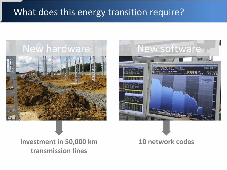
What does this energy transition require?
New hardware New software
Investment in 50,000 km transmission lines
10 network codes

EU council interconnection targets
Regional differences & needs must be considered
2020 10%
2030 15% ?

Ten Year Network Development Plan 2014
Pan-European Expert Group set up to perform pan-European Market Studies
Cost and Benefit Analysis (CBA) methodology for project of pan-European Significance
Multi-criteria approach Indicators quantified from market studies & grid studies
Increased stakeholder involvement in addition to the formal TYNDP consultation:
Creation of the Long Term Network Development stakeholder group
Early stage workshops on methodology and scenarios
Sole basis for the Projects of Common Interest selection

TYNDP + EU list of PCI = consistency
National Development
Plans
Regional reports
TYNDP report: Pan-European
relevance
PCIs: Projects of
Common Interest
Incorporating 22 third party projects
17 PCI projects assessed: • 8 transmission projects • 9 storage projects
120 projects of pan-European relevance
TYNDP 2014 package
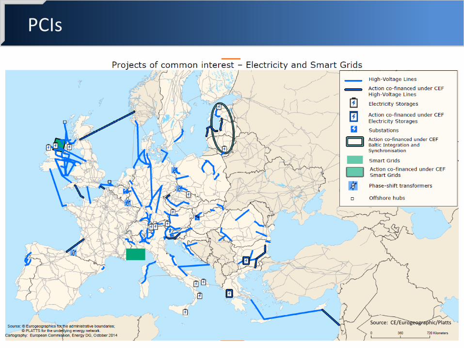
PCIs
Source: CE/Eurogeographic/Platts

TYNDP: Framing uncertainties to build the right infrastructure
On track for Energy Roadmap 2050
Delay of Energy Roadmap 2050
IEM HIGH IEM LOW
NATIONAL policy prvails
EUROPEAN policy prevails
NATIONAL policy prevails
EUROPEAN policy prevails
80% investments driven by RES!
60% RES 49% RES
Vision 3 Green
Transition
40 % RES
Vision 4 Green
Revolution
41% RES
Vision 1 Slow
Progress
Vision 2 Money
Rules
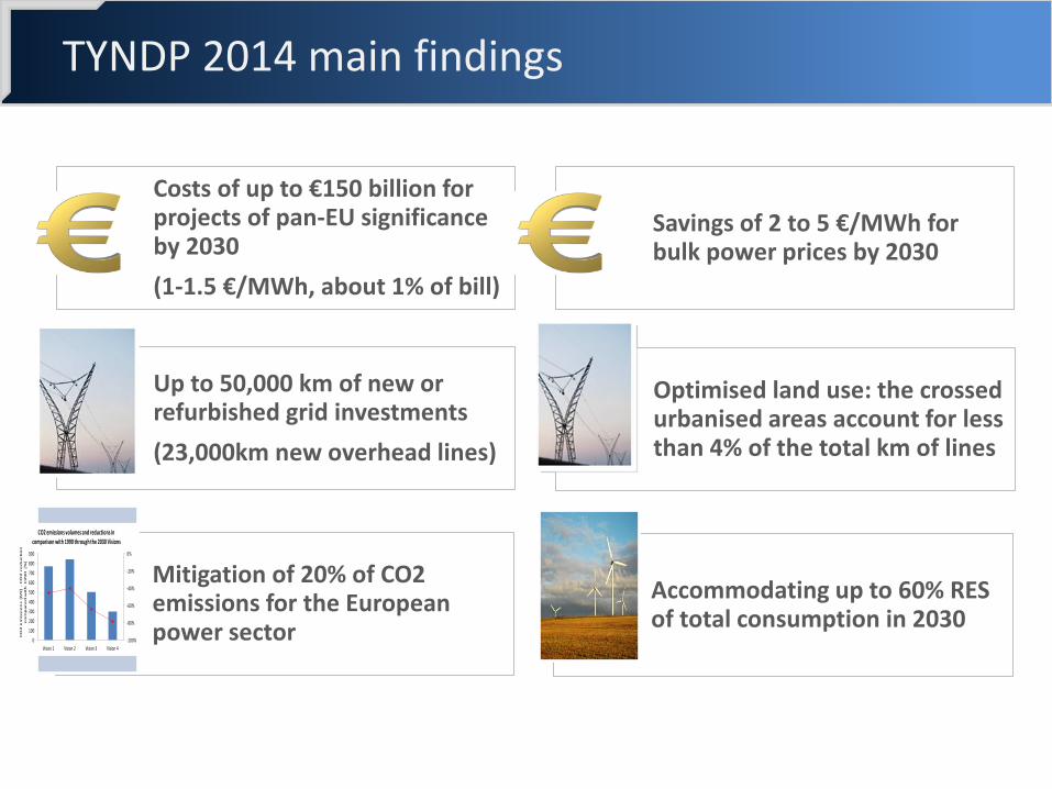
Costs of up to €150 billion for projects of pan-EU significance by 2030
(1-1.5 €/MWh, about 1% of bill)
Savings of 2 to 5 €/MWh for bulk power prices by 2030
Up to 50,000 km of new or refurbished grid investments
(23,000km new overhead lines)
Accommodating up to 60% RES of total consumption in 2030
Mitigation of 20% of CO2 emissions for the European power sector
Optimised land use: the crossed urbanised areas account for less than 4% of the total km of lines
-100%
-80%
-60%
-40%
-20%
0%
0
100
200
300
400
500
600
700
800
900
Vision 1 Vision 2 Vision 3 Vision 4
CO
2 e
mis
sio
ns [M
t] -
CO
2 r
ed
uc
tio
n
co
mp
are
d w
ith
1
99
0 [%
]
CO2 emissions volumes and reductions in comparison with 1990 through the 2030 Visions
TYNDP 2014 main findings
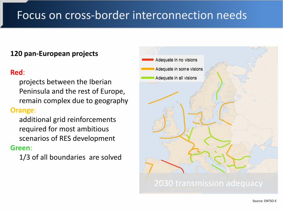
Focus on cross-border interconnection needs
120 pan-European projects Red:
projects between the Iberian Peninsula and the rest of Europe, remain complex due to geography
Orange: additional grid reinforcements required for most ambitious scenarios of RES development
Green: 1/3 of all boundaries are solved
2030 transmission adequacy
Source: ENTSO-E

• Procedures are lengthy and often cause commissioning delay
• 30% of investments are delayed by 2 years Permit granting
• More effort to bring citizens and interest groups on-board and increase understanding of Europe’s energy needs
Public acceptance
• Transmission infrastructure is a long term investment => a stable regulatory framework is crucial
• Tariffs must be adapted to support the energy transition Financing
Main obstacles to timely infrastructure building

New HVDC links are planned to be built all over Europe
Planned HVDC links are either:
located between 2 asynchronous areas, which can thus exchange power
embedded in a meshed synchronous area, where they enable bulk power transfer
Source: ENTSO-E
23
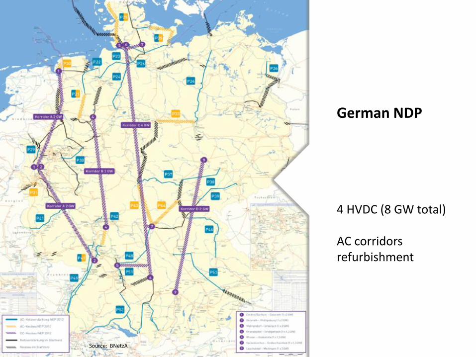
German NDP
4 HVDC (8 GW total) AC corridors refurbishment
Source: BNetzA

Electrical context of the grid
Evolutions of the European grid:
Development of renewable energy and in particular wind farms
Underground and submarine cables
More interconnections and HVDC projects
Several SVC Projects for grid security
Power electronics to be used more and more

HVDC FUNDAMENTALS
2
Source: Marshelec
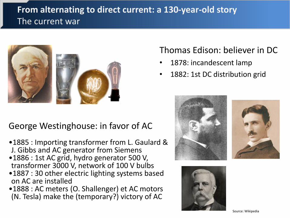
From alternating to direct current: a 130-year-old story The current war
Thomas Edison: believer in DC • 1878: incandescent lamp
• 1882: 1st DC distribution grid
George Westinghouse: in favor of AC •1885 : Importing transformer from L. Gaulard & J. Gibbs and AC generator from Siemens
•1886 : 1st AC grid, hydro generator 500 V, transformer 3000 V, network of 100 V bulbs
•1887 : 30 other electric lighting systems based on AC are installed
•1888 : AC meters (O. Shallenger) et AC motors (N. Tesla) make the (temporary?) victory of AC
Source: Wikipedia

DC assets vs. AC
Better control of power flows in meshed networks
Stable connection of asynchronous networks
Connection of AC networks operating at different frequencies (e.g. Japan)
Transmission capacity of lines and cables is saved in DC thanks to the absence of reactive power
30% less copper in the DC conductors to transmit same power as in AC
DC overhead/underground links have smaller environmental impacts

Relative costs of DC compared with AC
Converter stations significantly increase DC transmission costs
Break-even distances beyond which DC becomes cheaper than AC are around 40 km for cables and 500 km for OHL

Cost orders of magnitude
Power Total costs Cost by
converter Cost cable Incl. works
France-Espagne ( 67 km)
2 x 1000 MW
700 M€
150 M€
1,9 M€/km ( excl. tunnel)
Savoie-Piémont ( 95 km France )
2 x 600 MW
460 M€ ( France)
140 M€
3 M€/km ( France)
IFA2 ( 240 km)
1000 MW
670 M€
100 M€
0,9 M€/km
Midi-Provence ( 220 km)
1000 MW
500 M€
100 M€
1 M€/km

Nelson River 2
CU-project
Vancouver Island Pole 1
Pacific Intertie
Pacific Intertie Upgrading
Pacific Intertie Expansion
Intermountain
Blackwater
Itaipu
Inga-Shaba
Cahora Bassa
Brazil-Argentina Interconnection I
English Channel
Dürnrohr Sardinia-Italy Italy-Greece
Highgate
Chateauguay
Quebec – New England
Skagerrak 1&2 Skagerrak 3
Konti-Skan 1 Konti-Skan 2 Baltic Cable
Fenno-Skan
Gotland 1
Gotland 2
Gotland 3
Kontek SwePol
Chandrapur- Padghe
Rihand-Delhi
Vindhyachal
Sakuma Gezhouba-Shanghai
Three Gorges – Guangdong
Leyte-Luzon
Broken Hill
New Zealand 1
New Zealand 2
Three Gorges - Changzhou
Brazil-Argentina Interconnection II
Gotland
Murraylink
Directlink
Cross Sound Cable Eagle Pass
Tjæreborg
Hällsjön
Rapid City DC Tie
A world-wide used technology

Booming in North-West Europe (2030)

Line Commutated Current sourced converters
Converting stations using Graëtz bridge thanks to thyristors
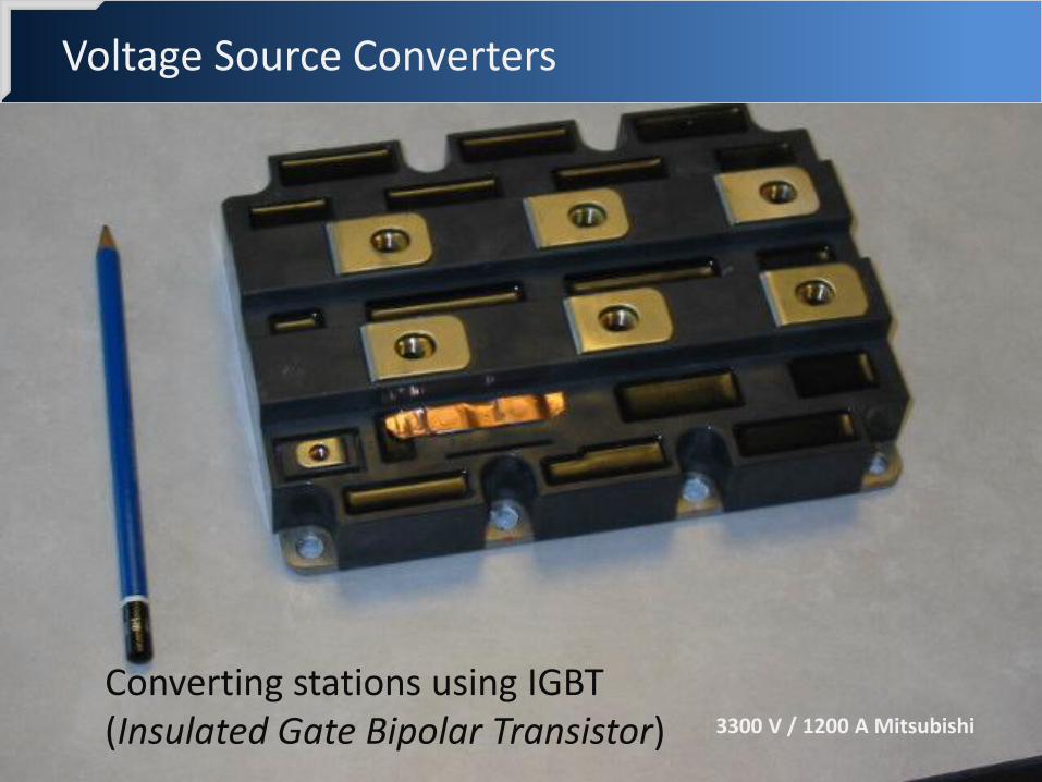
Voltage Source Converters
3300 V / 1200 A Mitsubishi
Converting stations using IGBT (Insulated Gate Bipolar Transistor)

Comparison LCC vs. VSC
LCC VSC
Semi conductor Thyristors "natural" commutation
IGBT forced commutation
Equivalent Current Source Voltage Source
Power reversal By polarity reversal of the DC voltage
Reversal of the flowing current direction
Line or Cable Overhead lines or mass-impregnated cables or oil filled cables
OHL or XLPE cables – cost effective and environmentally friendly
Reactive power Absorbs Q (~0,6 P) Supplies/Absorbs an adjustable Q
AC grid sensitivity LCC is subject to AC sags and can cause AC swells
Lesser sensitivity to AC sags
DC faults clearing Quick clearing without breakers
Low clearing due to AC breakers operation

VSC / Pulse Width Modulation (PWM)
+Vd
-Vd
+Vd
-Vd
UacUsw
High frequency Commutation (1 – 2kHz)

VSC / Modular Multi-level Converter (MMC)
36
Series connection of hundreds of modules independently controlled to build an ideally sine voltage wave

Major functionalities for TSO
Current
Power inversion flexibility
Voltage
U or Q control for each converting station, independent from P
Stability
Good dynamic and possibility for damping
Separate network
Black-start
Frequency control for a separate network

Key interconnection projects
FR-UK / ElecLink 1000 MW / 50 km
FR/ UK / IFA 2 : 1000 MW / 250 km / ~ 2020
FR-UK / FAB 1400 MW / 225 km
FR-ES / Bay of Biscay / 2 x 1000 MW / 360 km FR-IT / Savoie-Piemonte / 2x600
MW / 190 km / VSC / 2019
FR-IRL/ Celtic : 1000 MW / 500 km / ~ 2025
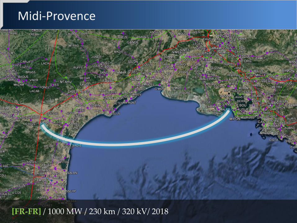
Midi-Provence
[FR-FR] / 1000 MW / 230 km / 320 kV/ 2018

INELFE EXAMPLE
3

INELFE cable description
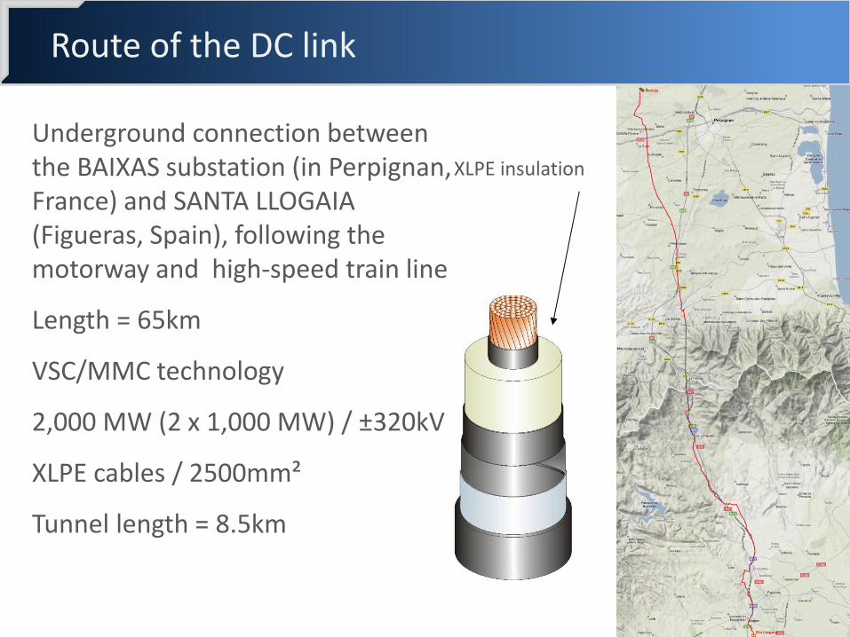
Route of the DC link
Underground connection between the BAIXAS substation (in Perpignan, France) and SANTA LLOGAIA (Figueras, Spain), following the motorway and high-speed train line
Length = 65km
VSC/MMC technology
2,000 MW (2 x 1,000 MW) / ±320kV
XLPE cables / 2500mm²
Tunnel length = 8.5km
XLPE insulation

Tunnel

Converter station in France
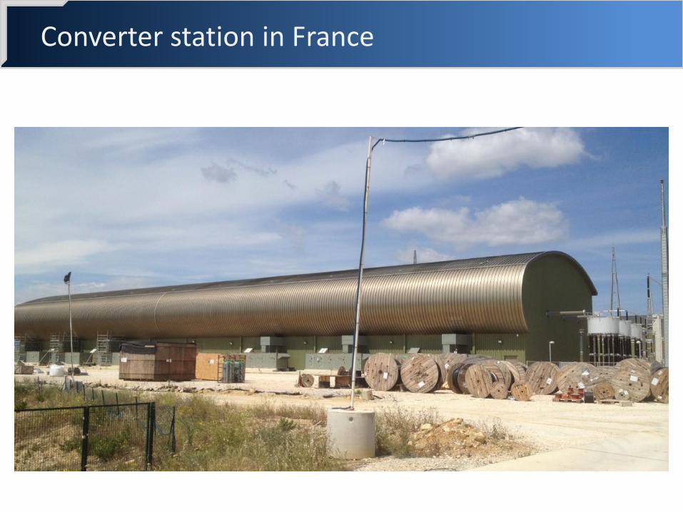
Converter station in France
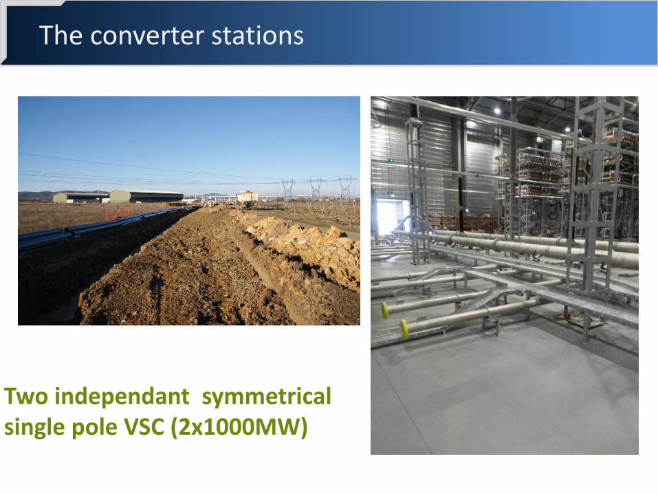
Two independant symmetrical single pole VSC (2x1000MW)
The converter stations

VSC Siemens
Control-
command room
Vers Poste
400kV
2*3 Transformateur
de puissance
monophasés + 1
pièce rechange
Two bipoles)
Fans
Têtes de
Câbles DC

HVDC INTEGRATION >>> ISSUES TO BE ADDRESSED
4
4

4 stages of increasing complexity
Stage 1 (in the past) Only one HVDC link between 2 asynchronous networks… FR-GB HVDC link until 2011
… or inside 1 synchronous network but with a huge electrical distance between the 2 converters Italy-Greece HVDC link since 2001
Stage 2 (recent years) Several HVDC links in parallel between 2 asynchronous networks HVDC links between Norway and continental synchronous zone FR-GB HVDC link + BritNed since April 2011

4 stages of increasing complexity
Stage 3 (now) HVDC links embedded in a meshed AC network Inside stage 3, there are also several stages of increasing complexity:
one HVDC link embedded in a meshed AC network and influencing 2 countries France-Spain HVDC link (2015) one HVDC link embedded in a meshed AC network and influencing more than 2 countries France-Italy HVDC link (2019) two HVDC links embedded in a meshed AC network and electrically close to each other Midi-Provence HVDC link
Stage 4 (to be designed) HVDC grids
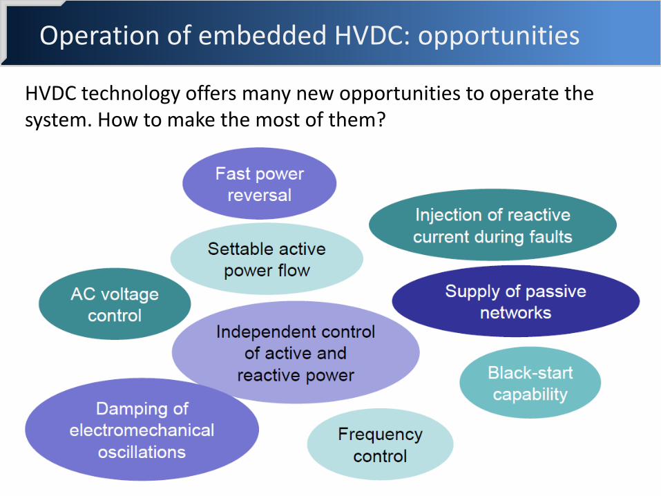
Operation of embedded HVDC: opportunities
HVDC technology offers many new opportunities to operate the system. How to make the most of them?
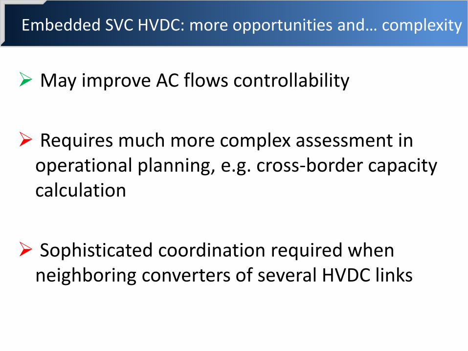
Embedded SVC HVDC: more opportunities and… complexity
May improve AC flows controllability
Requires much more complex assessment in operational planning, e.g. cross-border capacity calculation
Sophisticated coordination required when neighboring converters of several HVDC links

Active power management of embedded HVDC links Towards a hierarchy of controls for HVDC links?
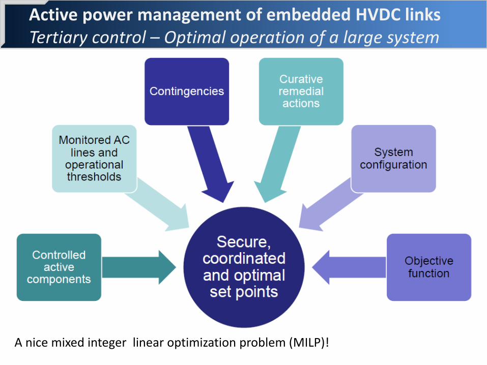
Active power management of embedded HVDC links Tertiary control – Optimal operation of a large system
A nice mixed integer linear optimization problem (MILP)!

FR-ES link example
The secondary control could monitor:
the AC interconnection lines
the supplying and evacuation lines of the HVDC link
The tertiary control could enable the operators to:
coordinate the set point of the HVDC link with the tap of Phase Shifters
calculate the admissible range of the HVDC power set point
or even maximize security margins on AC interconnection lines
Another solution
AC emulation
PHVDC = P0+ K * (δBAIXAS - δStLlog)

Further development needed…
Coordination will be essential when several HVDC links, possibly interacting with each other or with other active components, will be embedded into meshed AC networks
Innovative control necessary for a more global coordination of HVDC links that will offer more flexibility to the power system
Operation of embedded HVDC links is only beginning. Other challenges will have to be met as embedded HVDC links are commissioned

HVDC INTEGRATION >>> R&D ROLE
5
5
Source: ABB

SIMULATION
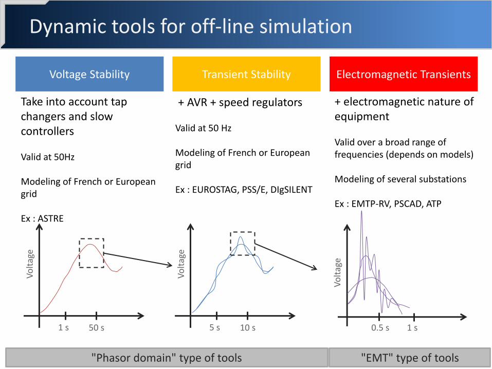
Dynamic tools for off-line simulation
Voltage Stability
Take into account tap changers and slow controllers Valid at 50Hz Modeling of French or European grid Ex : ASTRE
Transient Stability
+ AVR + speed regulators Valid at 50 Hz Modeling of French or European grid Ex : EUROSTAG, PSS/E, DIgSILENT
Electromagnetic Transients
+ electromagnetic nature of equipment Valid over a broad range of frequencies (depends on models) Modeling of several substations Ex : EMTP-RV, PSCAD, ATP
"Phasor domain" type of tools "EMT" type of tools
Vo
ltag
e
5 s 10 s V
olt
age
0.5 s 1 s
Vo
ltag
e
1 s 50 s

Difficulties with off-line simulations
Issues related to power electronic based equipment
Dynamic performances depend on complex control systems which are very difficult to model:
algorithms running on multiple cores with several time steps
proprietary algorithms confidentiality issues
excessive computing times on standard CPU
Need to use replicas of the real control system
Hypersim Simulator
Control System Replica
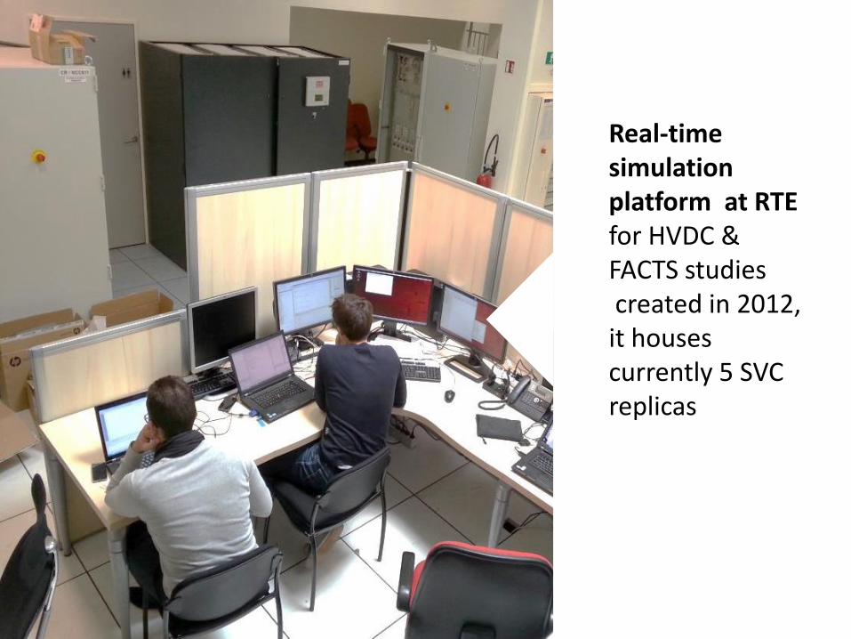
Real-time simulation platform at RTE for HVDC & FACTS studies created in 2012, it houses currently 5 SVC replicas

RTE real-time simulation laboratory
HVDC VSC - MAINTENANCE
HVDC VSC - STUDY HVDC LCC
SVC STUDY
SVC MAINTENANCE

DC CIRCUIT BREAKER
• 6

The DC high power circuit breaker: a bottleneck
Target:
320 kV DC in 2018
Today:
5273 A / 160 kV / 5,3 ms / 1,2 MJ
Key component of meshed grid for offshore wind farms

Alstom DC circuit-breaker
Source: Alstom
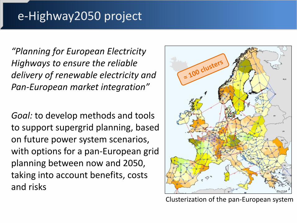
e-Highway2050 project
“Planning for European Electricity Highways to ensure the reliable delivery of renewable electricity and Pan-European market integration”
Goal: to develop methods and tools to support supergrid planning, based on future power system scenarios, with options for a pan-European grid planning between now and 2050, taking into account benefits, costs and risks
Clusterization of the pan-European system

Towards 100% DC grids ? A new chapter of electrotechnology…

CONCLUSION
6
6
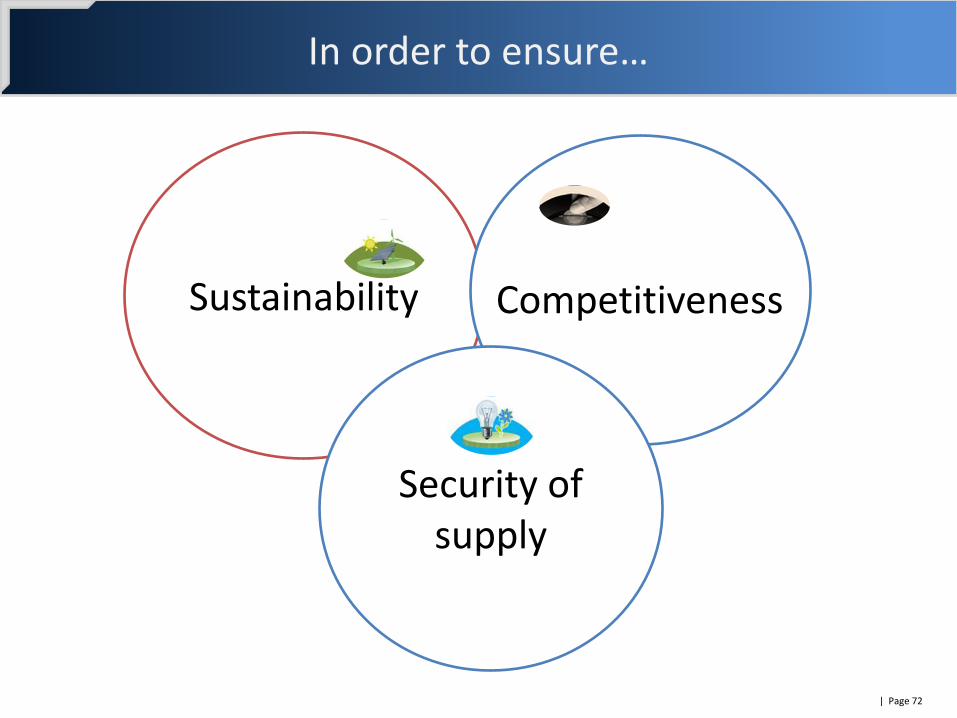
In order to ensure…
| Page 72
Sustainability
Security of supply
Competitiveness

… we need: A real thrust in infrastructure development A market redesign More R&D and innovation
Thank you for your attention