Embed Size (px)
Citation preview

Hurricane Ike Effect s on the Bolivar PeninsulaHurricane Ike Nature’s Force vs. Structural Strength
Hur
ric
ane
ike

September 2009
The Institute for Business & Home Safety (IBHS) is an independent, nonprofit, applied research and communications organization supported by the property insurance indus-try. IBHS’ mission is to reduce individual and societal costs inflicted by natural disasters and other risks to residential and commercial property. IBHS conducts world-class field and laboratory research, with the goal of identifying and promoting improved construc-tion, maintenance and retrofit practices.
The extensive research behind HURRICANE IKE: Nature’s Force vs. Structural Strength advances IBHS’ objectives in several critical ways, including:
providing a detailed, real-world performance evaluation of superior construc-•tion techniques when tested by a truly extreme weather event;
setting the course for rigorous laboratory testing to explore and resolve re-•maining issues with specific building materials and systems;
proving (once again) the importance of enacting and enforcing strong, ap-•propriate building codes – and proper elevation requirements in storm surge-prone areas; and,
showcasing the leading edge of construction and real estate markets, i.e., •developers choosing to design buildings to the highest standard, because they understand the favorable cost/benefit ratio and want to meet consumer demand for safety and durability.
Post-disaster field work like that performed for this report long has been a rich source of compelling data and information for IBHS and other loss mitigation research orga-nizations. However, IBHS is now engaged in an historic initiative that will substantially re-define and expand building science capabilities.
Once construction of the unique, multi-peril IBHS Research Center in Chester County, S.C. is complete in 2010, IBHS and our research partners will, for the first time, be able to subject full-scale homes, as well as light commercial and agricultural buildings to very realistic, severe hurricane conditions (including high-speed, gusty winds with vari-able droplet sized water injected into the wind stream). In addition, the IBHS lab will be able to replicate hailstorms, straight-line windstorms, and wildfire conditions - by generating wind-blown embers. Among other things, the data produced at the IBHS lab will be used to refine and improve construction material standards, building codes, and risk models.
Property valued at approximately $9 trillion sits along the Gulf and Atlantic Coasts from Texas to Maine. These vulnerable communities must do more to adapt to their perma-nent natural surroundings – which are beautiful most of the time, but perilous during hurricane season. Although HURRICANE IKE: Nature’s Force vs. Structural Strength focuses exclusively on Texas, the report’s findings and recommendations apply to all coastal jurisdictions. Policymakers and other stakeholders in coastal regions should take the lessons from this report seriously, and act upon them swiftly to ensure the safety and resiliency of their communities. As hurricane season 2009 continues to un-fold before us, there is no time to lose.
Sincerely,
Julie A. Rochman President & CEOInstitute for Business & Home Safety

4
7
8899
1111121415
20
2326
31
33
35363942
44
48
50
Table of contentsexecutive Summary
introduction
key Findings and recommendations: addressing coastal Property risk 1. Storm Surge 2. Roofing 3. Wind-Driven Water
Hurricane ike: nature’s Force vs. Structural Strength Setting the Stage: A Collision of Natural Force vs. Structural Strength Hurricane Ike: A Unique, Devastating Storm Structure Surge and Waves Ike in the Fortified Neighborhood (Bolivar) Performance of Traditionally Built Houses (Gilchrist and Bolivar Peninsula) Wind-Related Damage Performance of Fortified…for safer living® Homes (Audubon Village, Bolivar Peninsula)
Public Policy recommendations
references
a Guide to Strengthening coastal Properties in Texas Tier 1: The Roof and Water Intrusion Tier 2: Opening Protection, Gable Ends, Porches and Carports Tier 3: Developing Continuous Load Paths
appendix a History of building codes and flood elevation requirements
in the areas around Bolivar Peninsula, Texas
appendix B Institute For Business & Home Safety’s Fortified…for safer living® Program
appendix c Original IBHS code-plus Fortified criteria vs. Eligibility
requirements for homes seeking Texas Wind Pool Insurance

4 HURRICANE IkE: NATURE’S FORCE VS. STRUCTURAL STRENGTH
Executive Summary A few miles northeast of Galveston, Texas, is the Bolivar Peninsula, a 27-mile long barrier island with the Gulf of Mexico on one side and Galveston Bay on the other. In the early morning hours of Sept. 13, 2008, Hurricane Ike slammed into this narrow strip of land devastating its residential communities. Both in the size of its cloud mass and the integrated kinetic energy it contained, Ike was unlike any other hurricane that modern science has been able to observe in the Gulf of Mexico. The impact of this hurricane on the Texas Coast presented researchers with a valuable opportunity to observe the real-world performance of building materials, product standards and construction techniques. It also provided the first performance test of homes constructed to building code-plus criteria outlined by the Institute for Business & Home Safety’s (IBHS) Fortified…for safer living® program.
Researchers’ best estimates of what actually happened on the Bolivar Peninsula during Hurricane Ike – particularly in the vicinity of the development where homes were built to Fortified program criteria – include the following:
• Maximum3-secondgustwindspeedsrangingbetween 110 mph to 115 mph.
• Maximumsurgeof15feetto16feet,withwavesthatbroughthighestwaterlevels to between 19 feet and 20 feet.
• Maximumrainfallaccumulationofabout6inches.
• Maximumrainfallrateofabout1inchperhourovertwoperiodsduringthestorm.
Given these conditions, and the fact that the storm hit several well-populated areas (and pushed far inland with hurricane force winds), it is not surprising that Hurricane Ike was quite costly with respect to property losses. In fact, Ike ranks as the third costliest hurricane to make landfall in the United States, behind Hurricane Andrew, which caused $23.8 billion (2008 dollars) in insured losses in 1992, and Hurricane katrina, which caused $45.3 billion (2008) dollars in insured losses in 2005. Property losses from Ike total an estimated $12.5 billion across eight states; at least 115 deaths are directly linked to the storm.
Once the Bolivar Peninsula was reopened to traffic, a research team, which included IBHS staff, an engineer from an IBHS member insurance company, and a home builder who serves as an IBHS consultant, visited the area to survey the performance of traditionally built and Fortified homes. The IBHS team conducted limited ground surveys of traditional construction, as well as interior and external inspections of some Fortified houses and an extensive review of aerial photography.
More than $9 trillion of insured coastal property vulnerable to hurricanes sits along the Gulf and Atlantic Coasts from Texas to Maine. The number of coastal properties continues to rise, even though recent, challenging economic times have slowed that growth somewhat. In just the states of Florida, New York and Texas alone, there now is an estimated $5 trillion in combined insured property exposure. Additionally, with 50 percent of the nation’s population now living within 50 miles of the coast, the potential for increased storm-related deaths remains a concern. Lessons learned from Ike should be used to improve the ways in which homes and businesses are built in coastal zones, as well as to strengthen the standards used to govern the performance of construction

Executive S
umm
ary
5HURRICANE IkE
materials used in these areas. In addition, the observations can help determine which retrofits may be the most important as owners seek to strengthen existing buildings.
It is with these factors in mind that IBHS puts forth key findings and recommendations for reducing future property losses in all hurricane-exposed areas. The three key findings and recommendations are based on both post-Ike IBHS field research on the Bolivar Peninsula and a thorough review of building code requirements – and laid out in much more detail in the full research report.
A Texas-specific hurricane retrofit guide based on the research findings following Hurricane Ike can be found in this report. Geographically specific hurricane retrofit solutions for property owners and residents in other states along the Gulf and Atlantic coasts are in development and will be published by IBHS in 2010.
1. Storm Surge Current elevation requirements in surge-prone areas are not high enough.
These detailed findings and recommendations largely focus on the National Flood Insurance Program, and address how to accurately inform people about true flood risk and incentivize them to build well above the 1 percent annual probability of exceedance Base Flood Elevation (BFE), maximizing protection for homes.
2. Roofing New research is needed to assess actual performance of roofing products and systems in order to improve material production and installation specifications.
Much is known about how to effectively retrofit roofs to improve wind resistance, and IBHS provides detailed examples of critical steps that should be taken by homeowners to reduce wind damage and limit water intrusion in the accompanying retrofit guide. The Institute strongly recommends that steps be taken to address significant real-world performance differences among roof covers with the same nominal wind resistance rating. In order to do this, product testing should faithfully recreate the effects and loads experienced during hurricanes.
3. Wind-Driven Water Water intrusion must be better managed – through a combination of structural improvements and more realistic testing.
Some level of water penetration can occur even in well-protected homes. As a result, both structural and interior material choice is critical to prevent cascading damage, especially if electricity may be out for days. In addition, performance tests and acceptance levels for windows and doors must be improved to reflect real-world events.
When the vast majority of buildings are built at or slightly above the 1 percent annual probability of exceedance base flood elevation (BFE), all it takes is an event (i.e., Hurricanes Ike, Ivan, katrina or Rita) with surge levels a few feet above the BFE to wipe out the entire community.
These two homes were exposed to essentially the same wind conditions. The house on the right lost a few shingles, while the house on the left lost most of the roof cover. Two different products with the same nominal rating performed quite differently in real-world conditions.
When you build in an area where water is likely to get inside, the choice of building materials can make all the difference.


IntroductionThe Bolivar Peninsula, a 27-mile long barrier island a few miles northeast of Galveston, Texas, was ravaged by Hurricane Ike on Sept. 13, 2008. One year later, the 2.2 million cubic yards of debris left in Ike’s wake is still being removed from this narrow strip of land, which lies just north of the Gulf of Mexico and just south of Galveston Bay. Hurricane Ike’s devastating effects on the Bolivar Peninsula offered researchers an opportunity to investigate the performance of certain construction techniques and building materials, including those used to build numer-ous Fortified…for safer living® homes. The Fortified program, developed and administered by the Institute for Business & Home Safety (IBHS), requires building code-plus construction standards that greatly increase a new home’s resistance to natural perils.
HURRICANE IKE: Nature’s Force vs. Structural Strength illus-trates that it is possible to build homes that can withstand ex-treme hurricane conditions, but also points out that steps must be taken to improve building standards and products in order to better protect coastal properties. The key findings and rec-ommendations stemming from the research conducted by the IBHS engineering team are supported in the following pages through examples of construction failures and successes and comparisons between building code-plus and traditional con-struction techniques. The research also led to recommendations for strengthening the built environment through public policy and building code changes. These recommendations are outlined at the conclu-sion of this report. One of the chief recommendations is that coastal homes should be built well above current flood eleva-tion requirements to maximize protection from storm surge. The report also includes (in Appendix A) a brief history of build-ing codes and flood elevation requirements in the areas around Bolivar Peninsula, Texas.
In addition, an analysis of key elements of the wind-resistant construction requirements in the IBHS Fortified…for safer liv-ing® program and various Texas guidelines and building code requirements is offered in Appendix C.
As recent powerful hurricanes, including Ike, Ivan and katrina have shown, extreme storm surge can destroy entire neighbor-hoods in just a few hours. Public policymakers and the con-struction community should embrace the recommendations in this report as a roadmap for creating stronger communities.
More than 50 percent of the nation’s population now lives within 50 miles of the coast with more than $9 trillion of insured coastal property vulnerable to hurricanes from Maine to Texas. The number of coastal properties continues to rise, even though recent, challenging economic times have slowed that growth somewhat.
The only true avenue for protecting the homes and businesses that already populate the Gulf Coast and Eastern seaboard is through effective retrofit options.
A Texas-specific hurricane retrofit guide based on the research findings following Hurricane Ike can be found in this report. Geographically specific hurricane retrofit solutions for property owners and residents in other states along the Gulf and Atlan-tic coasts are in development and will be published by IBHS in 2010.
Most homes in coastal areas are built to or slightly above 100-year base flood elevations. A “100-year flood” means that the level of flood water has a one percent chance of being equaled or exceeded in any single year. However, it is well recognized in the engineering community that coastal homes built to this level have a 26 percent chance of being flooded or demolished over the life of a 30-year mortgage. This chance increases to about 40 percent over a 50-year period.
Chances for a building to survive can be significantly increased by employing what has been learned about the importance of proper elevation, which can be relatively inexpensive when constructing a coastal home. For example, building to a 500-year flood elevation reduces the chance of surge exceeding the base elevation to about 10 percent over a 50-year period. Some recommendations in this report do not involve construc-tion. For example, taking simple steps before evacuating when a hurricane threatens, such as rolling up area rugs, can greatly reduce the chance that mold will grow inside the home while the homeowner is not allowed back inside or the power is out.
While much has been learned through this and other IBHS post-disaster investigations, many questions remain unan-swered. IBHS is committed to further investigation and will have an even greater opportunity to explore building science with the opening the IBHS Research Center in Chester County, S.C., in 2010.

8 HURRICANE IkE: NATURE’S FORCE VS. STRUCTURAL STRENGTH
Key Findings and Recommendations: addreSSinG coaSTal ProPerTy riSkIBHS research conducted after Hurricane Ike has identified weaknesses in existing building code requirements, construc-tion product standards, and test methods, and proactive ap-proaches to limiting water damage. The following key findings and recommendations are intended to promote the strengthening of existing properties and the development of improved solutions for new construction.
1. Storm Surge: Current elevation requirements in surge-prone areas are not high enough.
The National Flood Insurance Program (NFIP) and coastal communities must consider whether the use of the 1 percent annual probability of exceedance flood elevation is a prudent minimum value.
• Duringthefirst30yearsoftheNFIP,theUnitedStates experienced a rapid increase in exposure to risk along the Gulf Coast due to the sheer number of new properties constructed and their high financial values. Furthermore, hurricane researchers agree that we currently are experiencing a period of increased hurricane activity in the Atlantic basin. Since the beginning of this period, numerous storms have made landfall in the U.S.; these storms produced very large storm surges that affected broad sections of the Gulf Coast. Among these hurricanes are Ike, Ivan, katrina and Rita.
• Mostelevatedcoastalhomesarewoodframestructures, and the evidence is clear that it only takes a few feet of water above the Base Flood Elevation (BFE) to wipe out all homes built at or below the minimum NFIP requirements. There essentially is no safety factor for homes in surge-prone areas other than additional height.
• NFIPshouldconsiderwaystoencouragehomeownersand builders to increase property elevation levels. Once a home has been elevated on properly anchored piles, it is likely that the incremental costs of raising the structure a few more feet would not be that significant. This could be accomplished by publishing both 1 percent and 0.2 percent probability of exceedance surge inundation maps that account for both still water rise and expected wave action and by incentivizing builders and homeowners to build above the 0.2 percent probability elevations.
• NFIPalsoshouldencouragecommunitiesdevastatedbyhurricanes that are rebuilding to raise the BFE above the published 1 percent probability of exceedance level.
• ItiscriticalthathomefoundationdesignfollowAmerican Society of Civil Engineers (ASCE) 24 requirements, with a proper accounting for wind, surge and debris loading. Special inspections of the foundation systems should be mandated in coastal surge areas.
• Onecautionarynoteisthatitisvirtuallyimpossibleto guarantee that a structure will not be destroyed if it is directly impacted by the eyewall of a major hurricane. Experience has shown that certain types of property, such as barrier islands and peninsulas, can literally be cut in two by a hurricane. Anything in such a storm’s path certainly will be devastated, regardless of foundation type or elevation.

Key Find
ings and
Reco
mm
endatio
ns
9HURRICANE IkE
2. Roofing: New research is needed to assess actual performance of roofing products and systems in order to improve material production and installation specifications.
• Roofcoverdamagecontinuestobethelargest,mostfrequent source of non-surge failures and losses related to hurricanes. Consequently, IBHS recommends that the roof be the first place owners and builders address in order to reduce future losses.
• Improvingroofperformanceiscriticaltoreducewinddamage and should be considered a primary point of investment for homeowners. The basic elements of strengthening roofs have been well known for some time, including improving attachment of the roof deck, providing backup protection from water intrusion, and installing a high-quality, wind-resistant roof cover.
• Strengtheningtheanchorageoftheroofshouldbethefirst step. The key is to use appropriately sized and spaced ring shank nails and concentrate on adding fasteners along structural members that support the interior portions of the sheathing. Usually, there are enough fasteners along the panel edges that failure is not initiated in this area.
• Improvementsmustbemadeinthespecifications relating to materials and installation methods of backup water protection on roofs. The new IBHS Research Center currently under construction should provide much-needed capabilities for such improvements. It is critical that other construction materials and techniques be assessed to ensure that various protective options will in fact achieve the necessary goals. Those goals are to keep water intrusion in the attic to a manageable level, where insulation will not become saturated, mold will not develop, and ceilings will not collapse.
• Stepsmustbetakentoaddressthesignificantdifferences between real-world performances of roof covers that have the same nominal wind-resistance designation. It is now possible to obtain a variety of roofing systems rated for high wind applications; however, there is no reliable way to test products by faithfully recreating the effects and loads experienced in a hurricane. As illustrated by the Fortified homes, roof covers that have the same nominal wind resistance designation can and do perform differently – and these differences show up in events that are less severe than the nominal performance-level designation. Most current test methods essentially use “pass or fail” criteria; as a result, it is not possible to clearly establish relative rankings for competing systems.
3. Wind-Driven Water: Water intrusion must be better managed – through a combination of protective measures, informed choices about water-resistant materials and more realistic testing.
When a hurricane strikes, it is usually not a question of whether water will enter the house and the wall cavities, but how much water will enter, and how much damage will result from that water intrusion.
• AULClassA-ratedroof,high-qualitywindowsanddoors,well-anchored soffit materials, well-anchored wind-resistant ridge vents, and shuttering or sealing other openings (such as gable end vents) will go a long way towards minimizing water intrusion.
• Coastalproperties,whereaccessmaybelimitedfor some time following a storm, or properties in locations where power may be out for some time following a storm, should be designed and constructed using flood-resistant building materials and systems. As illustrated by the Fortified homes, the fact that the builder used wood panels and boards for floors, ceilings, inside wall surfaces and outside wall surfaces resulted in significantly reduced losses and damage from water intrusion.
• Homeownersandbuildersmustrealizethatduring a hurricane some amount of water likely will find its way inside even in homes with a good roof, high quality windows and doors, well-anchored soffit materials, well-anchored wind-resistant ridge vents, and shuttered or sealed openings (such as gable end vents).
• Waterintrusiontestsmustbeimproved.Whilerainfall rates used in various current tests for windows and doors may be high, acceptance criteria for the products are set so low that all windows and doors are guaranteed to leak when a hurricane strikes.


11HURRICANE IkE
Hurricane Ike R
epo
rt
Setting the Stage: a colliSion oF naTural Force vS. STrucTural STrenGTH
The Bolivar Peninsula east of Galveston, Texas, was ground zero for Hurricane Ike in terms of highest surge levels and wind conditions. Virtually all structures built within a few hundred feet of the water along the Gulf Coast side of the Bolivar Peninsula were completely destroyed by storm surge. According to post-storm analyses by both the National Oceanic and Atmospheric Administration’s (NOAA) Hurricane Research Division and Applied Research Associates (ARA), a research and engineering company, the best estimates of 3-second peak wind gusts along the eastern portion of the peninsula were between 110 mph and 115 mph. Research observations also suggest most of eastern and southeastern Texas was subjected to tropical storm and hurricane-force winds for nine hours, and possibly longer.
In the heart of this surge-ravaged area were 13 homes (Figure 1) built by a single builder, which were designed and constructed in accordance with criteria outlined by the IBHS code-plus new construction program, known as Fortified…for safer living® [1]. The homes were built to the requirements created when the Fortified program was first launched in October 2000, and these requirements are a mixture of performance and prescriptive criteria. Hurricane Ike provided the first instance when homes built to these requirements were subjected to winds exceeding hurricane force.
The Fortified program provides design and construction requirements to make homes more resistant to natural disasters common in the location where they are built. In the case of the Bolivar Peninsula, the relevant natural peril is hurricanes. Fortified…for safer living® designations are awarded to houses that meet or exceed specific program criteria; this level of extra protection is verified through a series of inspections during construction.
One of the goals of the Fortified program is to assure that homes and businesses built to Fortified standards perform much better than neighboring structures (Figure 2) when a major natural catastrophe occurs. In the case of Hurricane Ike, 10 of 13 Fortified-designated homes remained standing with minimal damage, while all other homes in the surrounding area were totally destroyed. This clearly is a successful outcome.
A driving force behind the survivability of the Fortified homes was the combination of the IBHS program’s standards and the home design and construction material choices made by the homes’ builder, some of which may have been influenced by Fortified criteria. The three Fortified houses that did not survive actually were destroyed by the impact of debris from traditionally built homes knocked off their foundations by storm surge.
While Fortified homes performed exceedingly well compared to the more than 270 other surrounding homes on Bolivar Peninsula that were completely destroyed by Ike (Figure 3), they did sustain some damage. The key findings and recommendations contained here were formulated after IBHS compared and contrasted the performance of the Fortified homes with the conventional construction surrounding them, as well as examined relevant building code and other construction-related performance requirements. These research results can significantly improve the performance of both existing and new structures in hurricane-exposed areas.
Figure 1 IBHS Fortified…for safer living® houses before Hurricane Ike struck on Sept. 13, 2008. All of these homes are located on the north (inland) side of State Highway 87, the major coastal highway that runs the length of the Bolivar Peninsula, in the second row back from the Gulf of Mexico.
Figure 2 Older traditionally built homes before Hurricane Ike. These houses, located directly south of some of the Fortified homes in Figure 4, were on the narrow strip of land on the Gulf side of the highway before being destroyed by Ike.
Figure 3 An aerial view of nine of the 10 Fortified homes still standing following Hurricane Ike amid the rubble of other traditionally built houses that did not survive.
Hurricane Ike Nature’s Force vs. Structural Strength

12 HURRICANE IkE: NATURE’S FORCE VS. STRUCTURAL STRENGTH
HuRRIcane IKe: a unique, devaSTaTinG STorm STrucTure
WindS
At the height of the storm, Ike’s cloud mass essentially covered the entire Gulf of Mexico. The Wind and Surge Destructive Potential Classification Scale, which was detailed in Tropical Cyclone Destructive Potential by Integrated Kinetic Energy (by Dr. Mark Powell and Dr. Tim Reinhold, April 2007) offers a new way to assess hurricane size and strength by calculating the total kinetic energy contained in a 1-meter deep horizontal slice of the storm at an elevation of 10 meters above the land or ocean surface. Using this type of calculation, the integrated kinetic energy was calculated for Ike and was found to be 25 percent greater than the comparable maximum estimate for Hurricane katrina in 2005. Both estimates were performed using the National Oceanic Atmospheric Administration Hurricane Research Division H-Wind product [2]. Only in the Atlantic Ocean, where Hurricane Isabel cut new channels in the barrier islands along the Outer Banks of North Carolina, has a slightly larger estimated integrated kinetic energy been observed.
The breadth of the area impacted by high winds was another remarkable feature of Hurricane Ike. Wind field analyses, conducted using H-Wind [2] and Applied Research Associates’ [3] wind field models, suggest a 20-mile wide swath of winds at or very near the maximum values estimated for the storm, both as it neared the coast and as it made landfall. In this swath, the maximum 3-second wind gusts over water as the storm approached the coast have been estimated at about 125 mph, and the corresponding maximum over land 3-second gust wind speeds in the swath have been estimated at 115 mph.
Hurricane Ike made landfall just east of Galveston, Texas, at 2:10 a.m. CDT on Sept. 13, 2008 [4]. Prior to landfall, the diameter of tropical force winds was estimated to be 425 miles measured from northwest to southeast [4]. The National Hurricane Center classified Hurricane Ike as a Saffir-Simpson (SS) Category 2 storm at landfall with estimated maximum sustained winds over a water exposure of 110 mph [5].
Maximum sustained winds were estimated based on dropsonde data, flight level wind data obtained from hurricane reconnaissance flights, and the National Weather Service (NWS) Houston/Galveston WSR-88D Doppler Radar [6]. Wind field analyses, which were produced using the NOAA Hurricane Research Division’s H-Wind analysis program (Figure 4), suggest the maximum sustained (maximum 1-minute average) wind speeds at landfall right along the coast were likely between 95 mph and 100 mph and occurred east of the Bolivar Peninsula.
The 95 to 100 mph 1-minute sustained wind speeds correspond to 3-second duration gust wind speeds between 120 mph and 125 mph. The local NOAA Weather Service Office study of Ike that was prepared by Meteorologist Scott Overpeck [6] concluded that the maximum sustained wind speeds shown in the H-Wind analysis are reasonable, but possibly are on the high side. This was based on a detailed analysis of the maximum wind speed at various locations, where data was available, and from Doppler radar data adjusted to the standard 10-meter reference height for open terrain conditions [6].
Figure 4 Contours of equal maximum 1-minute sustained winds at 10-meter elevation for open terrain conditions generated from a series of H-Wind wind field plots and overlaid on a map of the the Texas Gulf Coast.
> 90
85-89
80-84
75-79
70-74
65-69
60-64
55-59
50-54
45-49
40-44
35-39
30-34
25-29
20-24
15-19
10-14

Hurricane Ike R
epo
rt
13HURRICANE IkE
A second estimate of wind speeds throughout the areas of coastal Texas and Louisiana affected by Hurricane Ike (Figure 5) was produced by Applied Research Associates (ARA) using a full two-dimensional numerical wind field model [2]. The results of this model are shown directly in terms of estimated 3-second duration gust wind speeds at 10-meter elevation over either a marine exposure, or an open terrain exposure depending on whether the location is over water or land.
In addition to the analyses that have been used to produce contour plots of maximum wind speeds, a number of universities deployed portable towers with meteorological instruments prior to Hurricane Ike’s arrival (Figure 6). Data from towers T0 through T5 have been used in the validation of the ARA model results and data from all of these sources have been considered in the analysis carried out by Overpeck [6].
As noted by Overpeck, the maximum wind speeds convey only part of the overall wind-related impact of Hurricane Ike on coastal and inland areas. Due to the size of the storm, many areas experienced winds exceeding hurricane force for several hours and the high winds in certain areas impacted buildings from a fairly broad range of wind directions. Based on his analysis of the storm, Overpeck notes, “…it is possible that tropical storm force winds affected most of southeast Texas for as much as 9 hours or longer. Hurricane force winds east of the eye of Ike could have affected portions of east Texas just as long.” [6]
Figure 5 Contours of equal maximum 3-second gust wind speeds produced by the ARA model overlaid on a map of the Texas Coast.
Figure 6 The track of Hurricane Ike and the locations of the meteorological instrument platforms on a Google Earth map.
> 110 mph
100-109 mph
90-99 mph
80-89 mph
70-79 mph
60-69 mph
<60 mph
10m meteorlogical towers (University of Florida, Louisiana State University)
2.5m Stick Net (Texas Tech University)

14 HURRICANE IkE: NATURE’S FORCE VS. STRUCTURAL STRENGTH
Surge and WavesA number of groups including the Federal Emergency Management Agency (FEMA), U.S. Geological Survey (USGS), and Harris County Flood Control District (HCFCD) conducted post-Ike surveys of high water marks and have published or are preparing reports on the results. Actual time histories of surge levels are available for the duration of the storm from three tide gauges located at the Galveston Pleasure Pier, United States Coast Guard (USCG) site in Freeport, Texas, and in Eagle Point, Texas [7]. A partial time history is available from the tidal gauge at Rollover Pass near the eastern end of the Bolivar Peninsula. In addition, the USGS deployed a temporary network of 117 pressure gauges at 65 sites along the coast and at inland locations in Texas and Louisiana. Data was recovered from 59 sites that included 41 surge sites, 10 riverine sites and eight beach/wave sites [8].
The eight beach/wave sites included two locations on Galveston Island; one toward the middle of the Bolivar Peninsula and another in Louisiana near the border with Texas. Based on the available data, it appears that surge levels at Galveston Island ranged from about 10 feet over the west end to 12 feet to 13 feet over the eastern portions.
Estimates of surge on Bolivar Peninsula range between 12 feet and 16 feet with the suggestion that it could have been higher in some locations [7]. The USGS beach/wave sensor on Bolivar [8] indicated a surge level of about 15 feet with peak wave heights ranging between 18 feet and 19 feet. Peak wave heights of between 17 feet and 19 feet were recorded over a three-hour period. An inland USGS temporary site on Bolivar, located close to the beach/wave site, recorded surge heights between about 13 feet and 13 1/2 feet for the better part of a four-hour period. Traces from several of the gauges suggested that an increase in water depth on the order of about 1 foot per hour was associated with the surge.
rainFall
Rainfall rates have been mapped out for the greater Houston area for the 24-hour period ending at 6 p.m. CDT on Sept. 13, 2008, by the HCFCD and estimated for outlying areas using Doppler radar [9]. Most of the area impacted by the strongest winds also experienced rainfall of 5 inches to 10 inches. Additionally, estimates of rainfall during the next 24 hours are available and indicated a rainfall accumulation of between 5 inches and 8 inches [9].

Hurricane Ike R
epo
rt
15HURRICANE IkE
Full size on page 16
Figure 8a Comparison of ARA wind field 15-minute average winds with 15-minute values at Tower T5. Figure 8b Comparison of ARA wind field model estimates with Tower T5 measurements. Figure 8c Comparison of ARA wind field model wind directions with measured wind directions at Tower T5. Figure 8d Comparison of ARA model estimates of central pressure drop vs. measured pressures at Tower T5.
Full size on page 16
Figure 9a ARA model estimates of gust wind speeds at site of Fortified houses on Bolivar Peninsula. Figure 9b ARA model estimates of wind direction at site of Fortified houses on Bolivar Peninsula.
Ike in the Fortified neighborhood (Bolivar)
WindS
Maximum gust wind speeds were estimated to be 115 mph at the site of the Fortified homes, based on a conversion of the H-Wind estimates of 1-minute sustained wind speeds over the eastern portion of the Bolivar Peninsula (90 to 92 mph) to 3-second gust wind speeds. This is consistent with the 116 mph maximum 3-second gust wind speed estimated by the ARA analysis for winds near the coast at this site.
The closest meteorological platform to the site was a 10-meter tower, T5, deployed by the Florida Coastal Monitoring Program (FCMP).
Comparisons of measured and estimated 15-minute average wind speeds, peak gust wind speeds, wind direction and central pressure drop at the T5 tower location are shown in Figures 8a through 8d. The comparison of gust wind speeds (Figure 8b) suggests that the ARA model slightly overestimates the peak gusts during the time period leading up to the arrival of the strongest winds in the eyewall. The plot suggests that T5 encountered the edge of the eye as shown by the dip in peak wind speeds at around 3 a.m. CDT. From about 2 a.m. CDT onward, the ARA model estimates of 3-second peak gust wind speeds correspond well with the measured peak 3-second gusts.
Peak 3-second gust wind speeds calculated using the ARA wind field model at the site of the Fortified homes on the Bolivar Peninsula are shown in Figure 9a. Assuming that the model overestimates the arrival of strong gusts in the first part of the storm by a similar time shift to that observed in the Figure 8a comparison, the houses would have been exposed to gust wind speed above 80 mph for about 10 to 11 hours and to peak gust wind speeds exceeding 100 mph for about seven hours. The wind directions associated with these wind gusts also have been estimated using the ARA wind field model and the results are shown in Figure 9b. A review of Figures 9a and 9b indicates that gust wind speeds in excess of 100 mph likely struck this area for a range of wind directions between about 60 and 190 degrees. Thus the homes would have been exposed to strong winds for about a 130-degree range of wind directions.

0
10
20
30
40
50
60
70
80
90
9/12/0818:00 9/12/0822:00 9/13/082:00 9/13/086:00 9/13/0810:00
15‐M
inute
Ave
rage
Win
dS
peed(m
ph)
Time(CDT)
ComparisonofARAWindfield15‐MinuteAverageWindswith15‐MinuteValuesatTowerT5
ARAModel
T5‐GillAnemometer
T5‐Propeller/vaneAnemometer
0
20
40
60
80
100
120
140
9/12/0818:00 9/13/080:00 9/13/086:00 9/13/0812:00
PeakGustWindSpeed(mph)
Time(CDT)
ARAModelFsGmatesoHGustWindSpeedsatSiteoHIoJGKedDesiLnatedMouses
ARAModel
0
20
40
60
80
100
120
140
9/12/0818:00 9/12/0822:00 9/13/082:00 9/13/086:00 9/13/0810:00
PeakGustW
indSpeed(mph)
Time(CDT)
ComparisonoCARAWindFeldModelIsJmatesKithToKerT5Measurements
ARAModel
T5‐GillAnemometer
T5‐Propeller/VaneAnemometer
8a 8b
0
45
90
135
180
225
270
315
360
9/12/0818:00 9/12/0822:00 9/13/082:00 9/13/086:00 9/13/0810:00
.i0
1D
iire
56o0
Time(CDT)
Com=>[email protected]?wiGHEe>?Ire1.i01Dire56o0?>G
TowerT5
ARAModel
T5‐GillAnemometer
T5‐Propeller/VaneAnemometer
950
970
990
1010
9/12/0818:00 9/12/0822:00 9/13/082:00 9/13/086:00 9/13/0810:00
Atm
osp
he
ric
Pre
ssu
reD
rop
(m
ba
r)
Time(CDT)
ComparisoAoBARAModelGsHmatesoBCeAtralPressureDropIersusMeasuredPressuresat
TowerT5KocaHoA
ARAModel
TowerT5Measured
8c 8d
9a
10a
9b
10b

Hurricane Ike R
epo
rt
17HURRICANE IkE
Full size on page 16
Figure 10a Surge/wave height above NAVD88. Figure 10b Surge height above NAVD88 at inland location on Bolivar Peninsula.
Figure 11 Locations of beach/wave surge sensor and surge measurement instruments as pictured in Google Earth.
SurGe
The USGS installed portable water depth measuring instruments at two locations near the middle of the Bolivar Peninsula. One was located near the beach and measured surge with waves (beach/wave gauge). The second was located nearby, but further inland, in an area that experienced little wave action. Results of the water depth measurements obtained from the two instruments, corrected for atmospheric pressure drop and referenced to the National Geodetic Vertical Datum, are shown in Figures 10a and 10b. The beach/wave gauge indicates a maximum surge (still water) height of about 15 feet with wave peaks between 18 feet and 19 feet. The inland gauge indicates a surge height of about 13 feet. Both of these gauges and partial storm data from a tidal gauge at Rollover Pass, which is closer to the site of the Fortified homes, indicate the water level was rising at a rate of about 1 foot per hour during the time when the surge height was most rapidly increasing. The locations of the gauges are shown in Figure 11. Other measurements of high water marks, which are part of an in-progress study, suggest that wave heights in some locations on the Bolivar Peninsula could have reached 20 to 21 feet.
Flood elevaTion requiremenTS
Flood Insurance Rate Maps for Galveston County became effective in April 1971. The initial 100-year flood elevation was 14 feet for the site nearest the Fortified homes on the Bolivar Peninsula. The elevation was decreased to 13 feet six years later.
In 1983, wave action effects were added to the flood elevations. This led to an increase in the flood height to about 17 feet inland of State Highway 87, where the Fortified homes were built, and to 19 feet above sea level on the seaward side of State Highway 87. However, no copies of the 1983 map were available for review.
Flood maps from 1992 and 1993 place the flood elevation at the site of the Fortified houses at 17 feet and at 19 feet for houses on the seaward side of State Highway 87. These same flood elevation heights remain in place as of this report. The maps indicate that the flood elevations are relative to the 1929 National Geodetic Vertical Datum (NGVD), and that the height of the reference mark, RM 4, was adjusted in 1978 and is 4.72 feet above the NGVD.

18 HURRICANE IkE: NATURE’S FORCE VS. STRUCTURAL STRENGTH
Figure 12 National Weather Service Doppler Radar (kGHX, League City, TX) cumulative precipitation estimates from radar in four cells surrounding site of Fortified houses on Bolivar Peninsula.
Figure 13 National Weather Service Doppler Radar (kGHX, League City, TX) cumulative precipitation estimates from radar in four cells surrounding site of Fortified houses on Bolivar Peninsula.

Hurricane Ike R
epo
rt
19HURRICANE IkE
Figure 14 Timing of selected Hurricane Ike effects.
rainFall
An analysis of rainfall estimated from Doppler radar cells near the site of the Fortified homes has been conducted by Forrest Masters at the University of Florida. The results are shown in Figures 12 and 13 (Page 18). Figure 12 shows estimates of rainfall rates in inches per hour during the passage of Ike over the site. Figure 13 shows a plot of the cumulative rainfall estimated from the data in Figure 12, which also indicates that most of the rainfall occurred during four periods when rain bands passed over the site. The maximum rainfall rate was on the order of 1 inch per hour. This is considerably less than the roughly 8 inches per hour rainfall rate typically used to test window, door and roof cover products. Nevertheless, as will be noted later, significant rainwater intrusion occurred in the houses that remained standing.
cHronoloGical Hurricane eFFecTS
The estimated timing of the various storm-related effects (wind speed, surge height with waves, and rainfall) at the site of the Fortified homes is shown in Figure 14. Each effect has been normalized by the maximum value, so that the results can be plotted using a single left-hand scale to emphasize timing. The wind direction is shown using the right-hand scale on the graph. The graph suggests that the peak surge occurred after the strongest easterly winds, but the surge was beginning to recede before the strongest southerly winds blew through the area. A large fraction of the rainfall followed the strongest easterly winds.
20 HURRICANE IkE: NATURE’S FORCE VS. STRUCTURAL STRENGTH
Figure 15 This home was dubbed the “Last House Standing” by the media, but did not perform as well as the houses built to the IBHS Fortified…for safer living® standard.
Figure 16 The wall of the first habitable floor on the seaward side of the “Last House Standing” had begun to fail when IBHS inspectors visited the site.
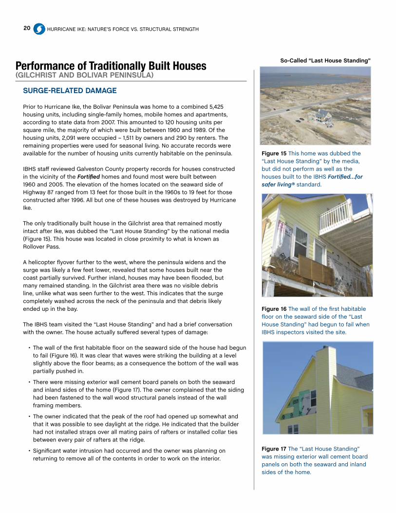
Figure 17 The “Last House Standing” was missing exterior wall cement board panels on both the seaward and inland sides of the home.
Performance of Traditionally Built Houses (GilcHriST and Bolivar PeninSula)
SurGe-relaTed damaGe
Prior to Hurricane Ike, the Bolivar Peninsula was home to a combined 5,425 housing units, including single-family homes, mobile homes and apartments, according to state data from 2007. This amounted to 120 housing units per square mile, the majority of which were built between 1960 and 1989. Of the housing units, 2,091 were occupied – 1,511 by owners and 290 by renters. The remaining properties were used for seasonal living. No accurate records were available for the number of housing units currently habitable on the peninsula.
IBHS staff reviewed Galveston County property records for houses constructed in the vicinity of the Fortified homes and found most were built between 1960 and 2005. The elevation of the homes located on the seaward side of Highway 87 ranged from 13 feet for those built in the 1960s to 19 feet for those constructed after 1996. All but one of these houses was destroyed by Hurricane Ike.
The only traditionally built house in the Gilchrist area that remained mostly intact after Ike, was dubbed the “Last House Standing” by the national media (Figure 15). This house was located in close proximity to what is known as Rollover Pass.
A helicopter flyover further to the west, where the peninsula widens and the surge was likely a few feet lower, revealed that some houses built near the coast partially survived. Further inland, houses may have been flooded, but many remained standing. In the Gilchrist area there was no visible debris line, unlike what was seen further to the west. This indicates that the surge completely washed across the neck of the peninsula and that debris likely ended up in the bay.
The IBHS team visited the “Last House Standing” and had a brief conversation with the owner. The house actually suffered several types of damage:
• Thewallofthefirsthabitablefloorontheseawardsideofthehousehadbegunto fail (Figure 16). It was clear that waves were striking the building at a level slightly above the floor beams; as a consequence the bottom of the wall was partially pushed in.
• Thereweremissingexteriorwallcementboardpanelsonboththeseawardand inland sides of the home (Figure 17). The owner complained that the siding had been fastened to the wall wood structural panels instead of the wall framing members.
• Theownerindicatedthatthepeakoftheroofhadopenedupsomewhatandthat it was possible to see daylight at the ridge. He indicated that the builder had not installed straps over all mating pairs of rafters or installed collar ties between every pair of rafters at the ridge.
• Significantwaterintrusionhadoccurredandtheownerwasplanningonreturning to remove all of the contents in order to work on the interior.
So-called “last House Standing”

Hurricane Ike R
epo
rt
21HURRICANE IkE
Figure 18 The concrete slab at ground level on the “Last House Standing” was significantly undermined by the effects of Hurricane Ike.
Figure 19 Houses near the Gulf of Mexico where the piles terminated at the bottom of the first floor tended to be completely wiped out by the storm surge.
Figure 20 A number of houses near the coast clearly had piles that continued through the height of the first floor. In these houses, the upper floors appeared to remain intact, but frequently the bottom floor and parts of the walls on the bottom floor were completely missing.
• Theconcreteslabatgroundlevelwassignificantlyundermined(Figure18).Itislikely that the slab will have to be broken up and removed in order to properly fill and compact soil under the slab.
Many coastal engineers very much oppose large concrete slabs being poured under elevated coastal homes. As was observed with the “Last House Standing,” it is possible to have significant undermining of the slab, which would require demolition of that slab. In some cases, the loads the slab imposes on the structure could pose a significant risk to the structure itself. The clear preference is for large concrete segments that are essentially giant pavers. These could be moved about by the surge, and then replaced after soil/sand under the house is replaced and compacted.
Farther west along the Bolivar Peninsula, where more houses in the second and third rows back from the water at least partially survived, it was possible to make some general observations concerning the performance of pile foundations.
Houses near the Gulf where the piles terminated at the bottom of the first floor (Figure 19) tended to be completely wiped out by the surge. This ceased when the houses were located far enough inland that wave action and surge height dropped below the bottom of the first elevated floor.
A number of houses near the coast clearly had piles that continued through the height of the first floor (Figure 20). In these houses, the upper floors appeared to remain intact, but frequently the bottom floor and parts of the walls on the bottom floor were completely missing.
elevaTion
Even the 19-foot elevation of homes on the seaward side of Highway 87 clearly was not sufficient to protect the homes from the storm surge generated by Ike. If the surge plus waves topped out at 20 feet to 21 feet, as indicated earlier in the report, then by simply rising a few feet above BFE the storm surge with wave effects completely destroyed all the homes, including those built after 1996. There is no substitution for enhanced elevation when it comes to extreme surge events. Unfortunately, extreme surge events have become increasingly common.
Of particular concern is the fact that there have been several storms in recent years that have subjected various parts of the Gulf Coast to surge levels much higher than the 1.0 percent probability per year (100 year return period) estimated surge levels. These include Hurricanes Ike, katrina and Ivan.
In light of these events, it would seem prudent for the NFIP to structure incentives to encourage more people to exceed the BFE by several feet and preferably above the 0.2 percent annual probability surge level (500 year return period) height. When all of the homes in a subdivision or community are essentially built at or below a single elevation, the risk that the entire area will be destroyed by extreme storm surge is greater. The Army Corps of Engineers and FEMA are currently working to remap surge inundation height around the U.S. coastlines. Hopefully, they will produce both the 1.0 percent and 0.2 percent annual probability of exceedance maps. This will provide an opportunity

22 HURRICANE IkE: NATURE’S FORCE VS. STRUCTURAL STRENGTH
Figure 21 One of the porch columns from a traditionally built house across the street from the Fortified homes on Bolivar Peninsula. Some of the posts that broke away from the houses damaged by storm surge became sizable battering rams, capable of damaging surrounding properties.
to better educate owners and developers on the surge risks and potential benefits of additional elevation.
The benefits of the enhanced elevation are clearly demonstrated by the decision of the Fortified…for safer living® builder. This particular builder opted to install decks at an elevation above the BFE, where most builders would construct the lowest habitable space. The builder then moved up the homes an additional 8 feet. If this had not been done, with a possible 21-foot surge plus wave height, the homes may not have survived. It is entirely possible that estimates of 0.2 percent probability of exceedance surge heights will exceed the BFE (1.0 percent annual exceedance level) for this part of the Gulf Coast by more than the 2-feet of freeboard required in the original Fortified criteria; by more than the 3-feet used in the current Fortified criteria, and by the NFIP for its maximum flood insurance discounts. This may also be true for many other parts of the Gulf Coast.
The NFIP and coastal communities need to carefully consider whether the use of the 1.0 percent annual probability of exceedance flood elevation is a prudent minimum value.
During the first 30 years of the NFIP, the country experienced a rapid increase in risk along the Gulf Coast due to the sheer number of new properties constructed and their value. Furthermore, all hurricane researchers agree that the United States and the Caribbean nations are experiencing a period of increased hurricane activity in the Atlantic basin.
Most elevated coastal homes are wood frame structures and the evidence is clear that it only takes a few feet of water above the BFE to wipe out all homes built at or slightly above the minimum BFE requirements. There essentially is no safety factor other than additional height. It should be noted that there is a 40 percent chance during a 50-year period that the surge will reach or exceed the 1.0 percent annual probability level; but, only a 10 percent chance that the surge will reach or exceed the 0.2 percent annual probability of exceedance level. Communities along the Texas coast that rebuild should be encouraged to raise the base flood elevations above the published 1.0 percent annual probability of exceedance level and to levels at or above the 0.2 percent annual probability of exceedance level.
FronT PorcHeS
The posts supporting many porches on houses in the surge area broke or came out of the ground. Some of the posts of porches that broke away became sizeable battering rams, capable of causing damage to surrounding properties. In other cases, the failures of the porch supports or the porches themselves threatened or actually damaged the home itself. Figure 21 shows one of the porch columns from a home across the street that impacted one of the Fortified designated homes.
It appears that owners or builders saved on construction costs by reducing the structural quality (embedment depth, concrete anchorage) of the posts supporting the front porches. It would seem prudent to either design porches and support structures to be break away or to ensure that the support structure is comparable to that of the house itself.
Hurricane Ike R
epo
rt
23HURRICANE IkE
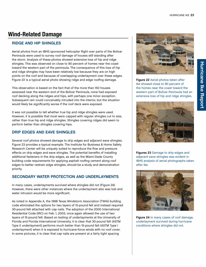
Figure 22 Aerial photos taken after Ike showed close to 90 percent of the homes near the coast toward the western part of Bolivar Peninsula had an extensive loss of hip and ridge shingles.
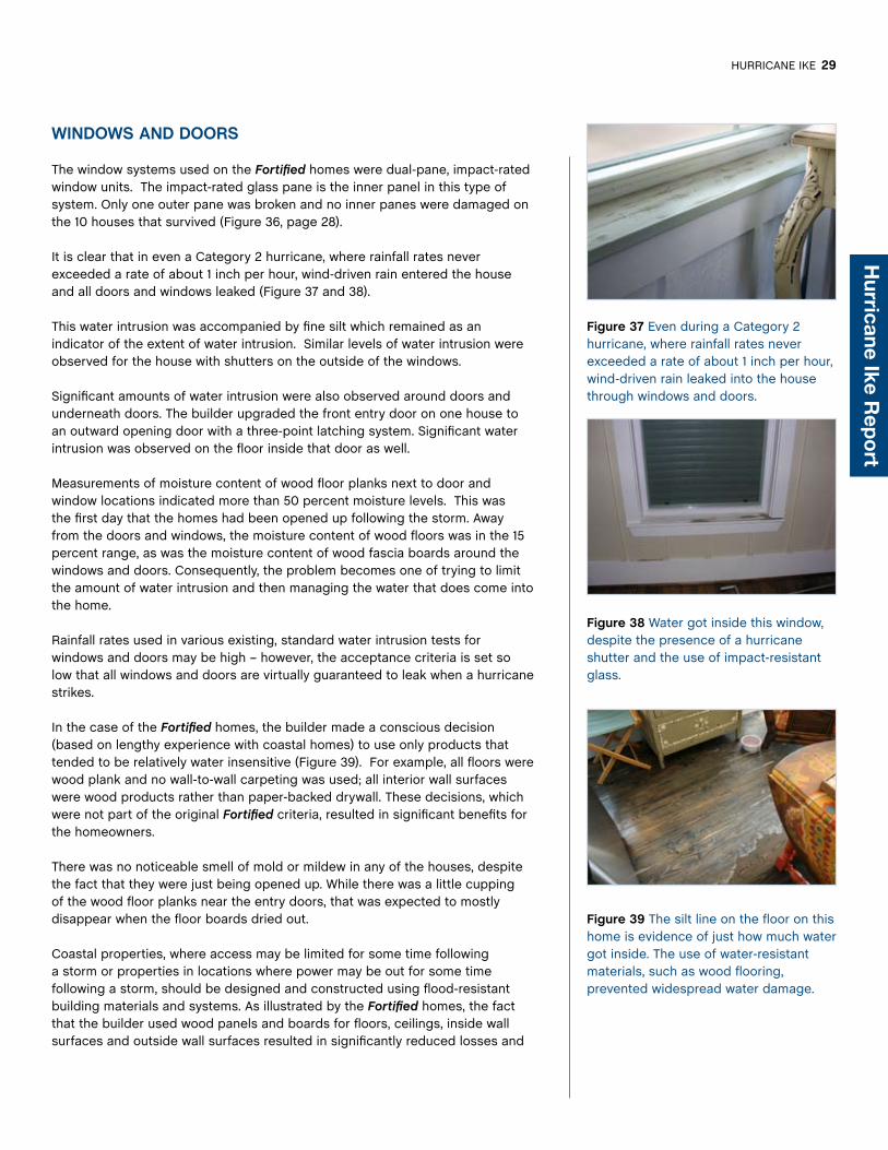
Figures 23 Damage to drip edges and adjacent eave shingles was evident in IBHS analysis of aerial photographs taken after Ike.
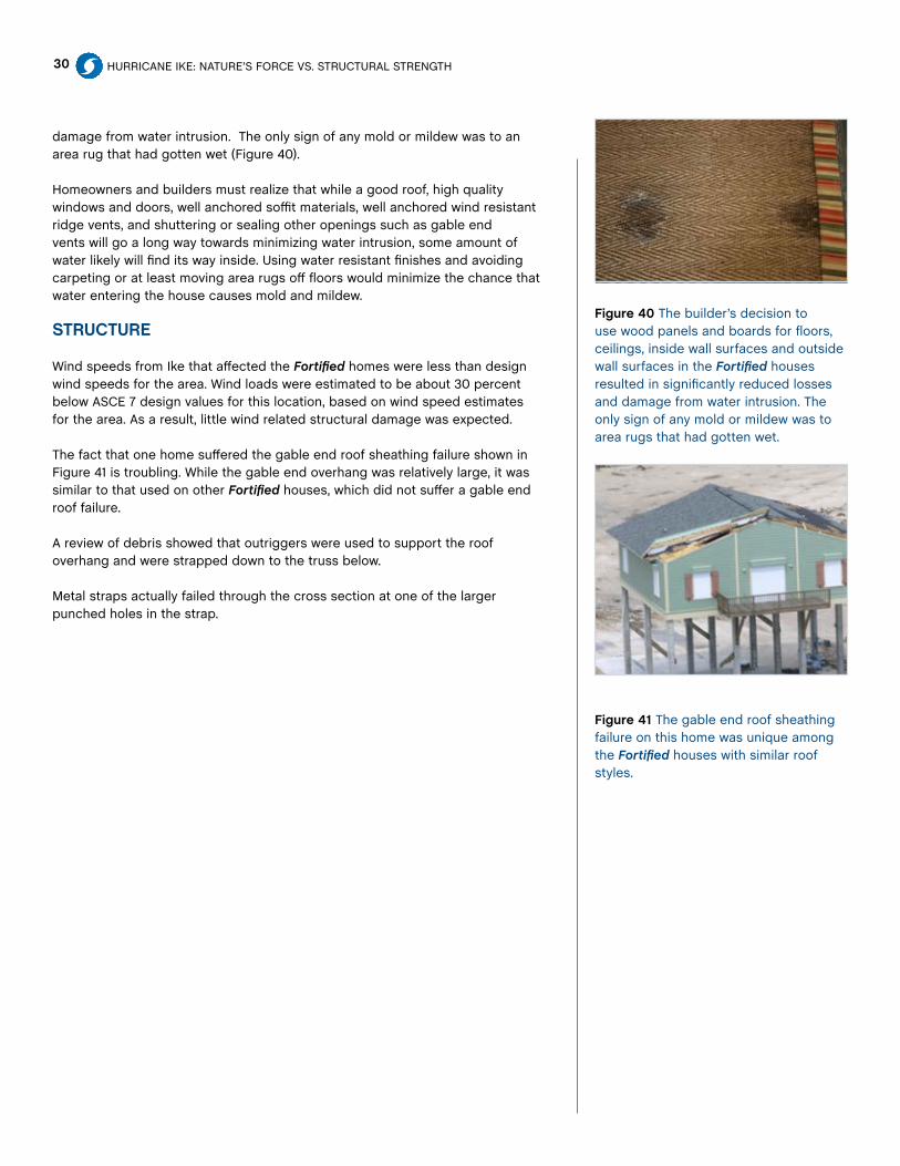
Figure 24 In many cases of roof damage, underlayment survived during hurricane conditions where shingles did not.
Wind-Related DamageridGe and HiP SHinGleS
Aerial photos from an IBHS sponsored helicopter flight over parts of the Bolivar Peninsula were used to survey roof damage of houses still standing after the storm. Analysis of these photos showed extensive loss of hip and ridge shingles. This was observed on close to 90 percent of homes near the coast toward the western part of the peninsula. The consequence of this loss of hip and ridge shingles may have been relatively low because they are on high points on the roof and because of overlapping underlayment over these edges. Figure 22 is a typical aerial photo showing ridge and edge roofing damage.
This observation is based on the fact that of the more than 150 houses assessed near the western end of the Bolivar Peninsula, none had exposed roof decking along the ridges and hips, with perhaps one minor exception. Subsequent rain could conceivably intruded into the interior, but the situation would likely be significantly worse if the roof deck were exposed.
It was not possible to tell whether true hip and ridge shingles were used. However, it is possible that most were capped with regular shingles cut to size, rather than true hip and ridge shingles. Shingles covering ridges did seem to perform better than shingles covering hips.
driP edGeS and eave SHinGleS
Several roof photos showed damage to drip edges and adjacent eave shingles. Figure 23 provides a typical example. The Institute for Business & Home Safety Research Center will be uniquely suited to reproduce the flow and pressure effects on drip edges and eave shingles. The potential benefits of installing additional fasteners in the drip edges, as well as the Miami-Dade County building code requirements for applying asphalt roofing cement along roof edges to better restrain edge shingles, should be a study and demonstration priority.
Secondary WaTer ProTecTion and underlaymenTS
In many cases, underlayments survived where shingles did not (Figure 24). However, there were other instances where the underlayment also was lost and water intrusion would be more significant.
As noted in Appendix A, the 1998 Texas Windstorm Association (TWIA) building code eliminated the options for two layers of 15-pound felt and instead required 30-pound felt attached with cap nails. The adoption of the 2000 International Residential Code (IRC) on Feb. 1, 2003, once again allowed the use of two layers of 15-pound felt. Based on testing of underlayments at the University of Florida and Florida International University, it is clear that 30-pound felt (ASTM Type II underlayment) performs much better than 15-pound felt (ASTM Type I underlayment) when it is exposed to hurricane-force winds with no roof cover. In some pictures, it is clear that cap nails are present at a fairly tight spacing

24 HURRICANE IkE: NATURE’S FORCE VS. STRUCTURAL STRENGTH
Figure 25 Flashing should have been installed at the joint where OSB sheathing panels overlapped on the primary slope of this traditionally built home, beginning at the ridge. This picture clearly shows that water collected and ran down through the gap between the sheathing.
on the underlayment that survived. However, it was not possible to determine whether the surviving underlayment was 30-pound felt.
FlaSHinG
Proper flashing can play an important role in reducing water intrusion and roof leaks. In at least one instance, where roof cover and underlayment was lost, it was clear that flashing had not been properly installed in a number of important areas.
The roof of this particular house (Figure 25) included a change in slope about half way down the main roof surface. This was accomplished by installing (Oriented Strand Board) OSB sheathing panels that overlapped the panels on the primary slope that began at the ridge (Figure 25). Flashing should have been installed over this joint. It is clear from the picture that water collected and ran down through the gap between the sheathing.
Proper flashing is also critical at all intersections between roofs and walls. Hurricane winds can easily drive water several inches up a wall, so the flashing needs to extend at least 5 to 6 inches up the wall.
SidinG
The fact that siding was stripped from some of the upper levels of the “Last House Standing,” but was not stripped from the Fortified designated homes or a number of other houses located to the west of the “Last House Standing,” suggests that installation and fastening of siding is critically important.
Similar performance issues have been observed in other storms. The performance of vinyl siding on double-wide manufactured homes hit by Hurricane Charley in 2004 is a case in point. In home after home, siding installed at the factory stayed on, while siding installed in the field where halves were mated together was missing.
There have been recent efforts to use quasi-steady methods to quantify the loads on various layers of built-up walls. Code change proposals addressing these loads have been submitted in recent update cycles for the IRC and IBC as well as in the current ASCE 7 Wind Loads Subcommittee’s activities. The goal is to define the portion of wind load (a reduced load level) that will be applied to exterior siding when there is some level of pressure equalization across the layers.
rooF STrucTure
The separation of roof structure at the ridge for the “Last House Standing” underscores the importance of properly connecting rafters on opposite sides of the ridge beam.
Since wind speeds on the Bolivar Peninsula are thought to have been on the order of 115 mph gusts, the wind loads on the roof of that house likely were about 30 percent lower than the design loads. This raises questions about prescriptive requirements for collar ties or strapping on every third, or every other, set of rafters. These requirements have been part of high wind construction prescriptive guidelines for some time. However, it is not possible to be completely sure that wind was the only contributor to this separation. Forces

Hurricane Ike R
epo
rt
25HURRICANE IkE
Figure 26 The 15-pound felt underlayment in this home did not survive hurricane conditions after the shingles were lost. This problem was addressed in the Fortified homes through the use of tape over the seams to provide backup water protection.
Figure 27 Losses of roof sheathing at gable ends were frequently observed toward the western end of the Bolivar Peninsula, where the 3-second gust wind speeds were likely less than 110 mph.
Figure 28 Gable end failures, and particularly of roof sheathing loss at gable ends, were a frequent source of damage. In several cases, it was clear that outriggers supporting sheathing had been notched, and in some instances, underlying rafters or trusses also probably were notched.
produced by surge and waves interacting with the house may have added to distress of the roof structure.
rooF SHeaTHinG aTTacHmenT
Several instances of roof sheathing loss and loss of sheathing at gable ends were observed toward the western end of the Bolivar Peninsula, where the 3-second gust wind speeds were likely less than 110 mph (Figures 26 and 27).
These observations correspond to about 40 percent lower loads than those anticipated in ASCE 7 or the IRC. However, given relatively weak prescriptive guidance provided until the 1998 TWIA code was adopted, failures are not surprising. No failures of roof sheathing created using planking were observed. Planks historically have been attached more securely than wood structural panels because two nails are usually applied at every point where a plank crosses a framing member.
One of the first objectives for retrofitting houses built prior to 1998 or houses that were not built to at least the enhanced TWIA roof sheathing attachment requirements is to strengthen the roof sheathing attachment.
GaBle end overHanGS
Several instances of gable end failures, and particularly of roof sheathing loss at gable ends, were observed (Figure 28). In several cases, it was clear that outriggers supporting sheathing had been notched, and in some instances, underlying rafters or trusses also probably were notched.
Another high-priority item for evaluating homes with gable ends is to determine how roof sheathing is attached and how structural elements supporting the overhang are arranged and fastened together.
A more complete structural retrofit guide for gable ends is available free to the public on the IBHS Web site (www.DisasterSafety.org), including a video demonstration.

26 HURRICANE IkE: NATURE’S FORCE VS. STRUCTURAL STRENGTH
Figures 29 and 30 Ground level views, looking west, of the Fortified houses before and after Hurricane Ike. It is clear that all storage areas and decks were totally destroyed by the storm surge.
Figure 31 While all of the decks did break away, it is clear that deck connections were not what typically would be considered a breakaway connection in the Coastal Construction Guidance from FEMA and the NFIP.
Performance of Fortified…for safer living® Homes (auduBon villaGe, Bolivar PeninSula)
During a meeting with the Fortified home builder, the IBHS team gained access to interiors and roofs of selected homes, and generally assessed the performance of all Fortified-designated homes that remained standing after Ike. Ten of the 13 Fortified homes built on the north side of Highway 87 in Gilchrist survived Hurricane Ike. An examination of broken support columns from the three Fortified houses that were destroyed (all located directly across the street from traditionally built homes) strongly indicated that the failure of all three homes was caused by debris impact from the traditionally built destroyed houses across the street.
Figure 29 provides a ground level view, looking west, of the Fortified designated homes prior to Hurricane Ike. Figure 30 provides a similar view after Ike.
SurGe-relaTed damaGe and FoundaTion deSiGn
A comparison of Figures 29 and 30 shows that all storage areas and decks were totally destroyed by the surge from Hurricane Ike. Building elevation survey documents for these houses indicate that the bottom of the lowest horizontal member of the decks were typically at an elevation of about 18 feet above mean sea level. The BFE in this area was 17 feet, and the surge plus wave height from Ike is estimated at about 19 feet to 20 feet.
While all of the decks did break away, it is clear that deck connections (Figure 31) were not what typically would be considered a breakaway connection in the Coastal Construction Guidance from FEMA and the NFIP. However, this was not a requirement because the deck was above the BFE. In a few cases, deck failure damaged columns to which the decks were attached, but there is no indication that this was a factor in overall performance of any of the houses that were destroyed.
While Hurricane Ike represented an extreme surge event, the winds were below design level. Consequently, while it was a good test of the foundations, it was not a true design case. Wind loads could have been as much as 30 percent higher. The height of the surge probably actually further reduced wind loads because it effectively made the homes shorter relative to wind action for a significant part of the storm.
The increase in design wind speed that has been adopted as part of the revised Fortified program will help improve lateral resistance of the foundation design, because it will impose larger lateral loads on the elevated building. Fortified design requirements also have been expanded to include reference to ASCE 24, which addresses design loads for pile foundations in storm surge areas.

Hurricane Ike R
epo
rt
27HURRICANE IkE
Figure 32 These horizontal cracks are indicative of the columns experiencing large tension forces from uplift on the decks when they were impacted by the storm surge with waves. If the cracking had been due to lateral loads, it would have produced diagonal cracks across the cross-section.
Figure 33 Here staples were used in an apparent attempt to keep the secondary water barrier tape in place, likely due to the fact that the tape was not sticking well when it was first applied.
Figure 34 Workers opted to use a different type of secondary water barrier tape than was used on one of the last Fortified houses in the row on Bolivar Peninsula.
SuPPorT columnS
The support columns suffered local damage in a number of instances when the decks were destroyed. In addition, most of the columns exhibited small horizontal cracks below the deck connection points that ran around the entire circumference of the columns. These horizontal cracks are indicative of the columns experiencing large tension forces from uplift on the decks when they were impacted by the storm surge with waves. If the cracking had been due to lateral loads, it would have shown up as diagonal cracks across the cross-section. Figure 32 illustrates the cracking of the columns.
Cracking could have been prevented if deck boards had been more weakly restrained against uplift by using smaller or smoother fasteners to attach boards to supporting beams.
rooFS
The roofs of the Fortified homes experienced significant damage to coverings and underlayment. These topics have been identified as areas for additional improvement in program criteria. The roofs had been provided with a secondary water barrier in the form of a self-adhering modified bitumen tape that was installed over the seams between the roof sheathing. For these houses, the roof sheathing was ⅝-inch thick OSB.
Secondary Water Barrier These roofs provided the first opportunity to assess how well the secondary water barrier performed because it is the first time, according to IBHS records, where the roof cover was lost on a roof outfitted with this type of tape.
An in-person, roof-top inspection of the secondary water barrier tape on one of the houses showed that this particular product, which looked more like window flashing tape, did not adhere very well to the roof surface – despite the fact that it had been well-heated by the summer sun.
The use of staples, in an apparent attempt to keep the material in place, also made it clear the workers were aware of the fact that the tape was not sticking well when they first applied it (Figure 33). It appeared that a different type of tape was used on one of the last houses in the row (Figure 34). Photographs and ground observations gave the appearance that this particular tape adhered better, but no access to the roof was available for a close-up inspection.
The poor adhesion of the tape to the OSB reinforces an observation first encountered with the LA House; a demonstration house built by the Louisiana State University Extension Program in Baton Rouge, La., which was constructed using Fortified criteria.
LA House included a mixture of plywood sheathing on part of the roof and Structural Insulating Panels (SIPs) with OSB sheathing elements on another

28 HURRICANE IkE: NATURE’S FORCE VS. STRUCTURAL STRENGTH
Figure 35 Drip edges may be vulnerable to corrosion and may play a role in eave shingle failures when they are not attached with enough fasteners. In this photo, the drip edge is deflected upward and may have contributed to the lifting of shingle tabs immediately adjacent to the eave.
Figure 36 Only one outer pane was broken and no inner panes were damaged on the impact-resistant windows used in the 10 Fortified houses that survived Hurricane Ike.
part of the roof. The roof was completely covered with a self-adhered modified bitumen membrane but no roof cover when Hurricane katrina struck.
Despite the fact that the winds from Hurricane katrina were not particularly strong in Baton Rouge, all of the membrane was lost from the SIP panels. In contrast, the membrane on the plywood panels remained in place.
A subsequent review of the manufacturer’s recommendations for installation on OSB revealed that the OSB should have been primed before installation of the membrane. The builder then primed the OSB and new membrane was installed. A few weeks later, Hurricane Rita struck with higher winds in Baton Rouge. However, this time none of the membrane was lost.
Drip Edges These edges may be vulnerable to corrosion and may play a role in eave shingle failures when they are not attached with enough fasteners. Figure 35 shows an instance where the drip edge is deflected upward and may have contributed to the lifting of shingle tabs immediately adjacent to the eave.
Underlayment The Fortified program allows use of two layers of 15-pound felt as one underlayment option. This was the option selected for the Bolivar Fortified homes. The original Fortified Builder’s Guide provided directions for attaching the felt with fasteners that use load distribution disks or capped head nails. The new guide only specifies attachment details for cases where the underlayment is being used as the primary source of secondary water protection. It is clear that ASTM Type I (15-pound) felt does not perform well when the primary roof cover is damaged. This is true even when the felt is relatively new (less than two years old), installed using plastic cap nails, and exposed to wind speeds of 110 mph to 115 mph.
Roof Covers The roof covers installed on the Fortified houses were H-rated products, which implies a nominal rating for installation in areas with design wind speeds of up to 150 mph, according to the new ASTM D7158 rating system. The home builder indicated problems with the loss of shingles in thunderstorms prior to Hurricane Ike. A change in brands was made and applied to the last house built before Ike struck.
The last house to be roofed only lost a few shingles near the lower corner on the windward edge of the gable end. It is assumed that the products were installed in a similar fashion since the same crews provided the installations. This suggests that there remain significant differences between roof cover products with the same nominal designation.
It is clear that roof cover materials and test methods need a thorough review. Roofs and roofing products and systems will be a major focus of the new IBHS Research Center agenda for the first few years.
Hurricane Ike R
epo
rt
29HURRICANE IkE
Figure 37 Even during a Category 2 hurricane, where rainfall rates never exceeded a rate of about 1 inch per hour, wind-driven rain leaked into the house through windows and doors.
Figure 38 Water got inside this window, despite the presence of a hurricane shutter and the use of impact-resistant glass.
Figure 39 The silt line on the floor on this home is evidence of just how much water got inside. The use of water-resistant materials, such as wood flooring, prevented widespread water damage.
WindoWS and doorS
The window systems used on the Fortified homes were dual-pane, impact-rated window units. The impact-rated glass pane is the inner panel in this type of system. Only one outer pane was broken and no inner panes were damaged on the 10 houses that survived (Figure 36, page 28).
It is clear that in even a Category 2 hurricane, where rainfall rates never exceeded a rate of about 1 inch per hour, wind-driven rain entered the house and all doors and windows leaked (Figure 37 and 38).
This water intrusion was accompanied by fine silt which remained as an indicator of the extent of water intrusion. Similar levels of water intrusion were observed for the house with shutters on the outside of the windows.
Significant amounts of water intrusion were also observed around doors and underneath doors. The builder upgraded the front entry door on one house to an outward opening door with a three-point latching system. Significant water intrusion was observed on the floor inside that door as well.
Measurements of moisture content of wood floor planks next to door and window locations indicated more than 50 percent moisture levels. This was the first day that the homes had been opened up following the storm. Away from the doors and windows, the moisture content of wood floors was in the 15 percent range, as was the moisture content of wood fascia boards around the windows and doors. Consequently, the problem becomes one of trying to limit the amount of water intrusion and then managing the water that does come into the home.
Rainfall rates used in various existing, standard water intrusion tests for windows and doors may be high – however, the acceptance criteria is set so low that all windows and doors are virtually guaranteed to leak when a hurricane strikes.
In the case of the Fortified homes, the builder made a conscious decision (based on lengthy experience with coastal homes) to use only products that tended to be relatively water insensitive (Figure 39). For example, all floors were wood plank and no wall-to-wall carpeting was used; all interior wall surfaces were wood products rather than paper-backed drywall. These decisions, which were not part of the original Fortified criteria, resulted in significant benefits for the homeowners.
There was no noticeable smell of mold or mildew in any of the houses, despite the fact that they were just being opened up. While there was a little cupping of the wood floor planks near the entry doors, that was expected to mostly disappear when the floor boards dried out.
Coastal properties, where access may be limited for some time following a storm or properties in locations where power may be out for some time following a storm, should be designed and constructed using flood-resistant building materials and systems. As illustrated by the Fortified homes, the fact that the builder used wood panels and boards for floors, ceilings, inside wall surfaces and outside wall surfaces resulted in significantly reduced losses and
30 HURRICANE IkE: NATURE’S FORCE VS. STRUCTURAL STRENGTH
Figure 40 The builder’s decision to use wood panels and boards for floors, ceilings, inside wall surfaces and outside wall surfaces in the Fortified houses resulted in significantly reduced losses and damage from water intrusion. The only sign of any mold or mildew was to area rugs that had gotten wet.
Figure 41 The gable end roof sheathing failure on this home was unique among the Fortified houses with similar roof styles.
damage from water intrusion. The only sign of any mold or mildew was to an area rug that had gotten wet (Figure 40).
Homeowners and builders must realize that while a good roof, high quality windows and doors, well anchored soffit materials, well anchored wind resistant ridge vents, and shuttering or sealing other openings such as gable end vents will go a long way towards minimizing water intrusion, some amount of water likely will find its way inside. Using water resistant finishes and avoiding carpeting or at least moving area rugs off floors would minimize the chance that water entering the house causes mold and mildew.
STrucTure
Wind speeds from Ike that affected the Fortified homes were less than design wind speeds for the area. Wind loads were estimated to be about 30 percent below ASCE 7 design values for this location, based on wind speed estimates for the area. As a result, little wind related structural damage was expected.
The fact that one home suffered the gable end roof sheathing failure shown in Figure 41 is troubling. While the gable end overhang was relatively large, it was similar to that used on other Fortified houses, which did not suffer a gable end roof failure.
A review of debris showed that outriggers were used to support the roof overhang and were strapped down to the truss below.
Metal straps actually failed through the cross section at one of the larger punched holes in the strap.

Public Policy RecommendationsBased on the damage observations following Ike and a review of the building codes and history of code adoption and enforcement in Texas, IBHS recommends the fol-lowing Texas specific actions:
Adopt Texas Department of Insurance (TDI) developed building codes •and guidelines in Tier 1, 2 and 3 counties from the coast.
For jurisdictions having a building department, assign primary respon-•sibility for inspections and enforcement of the TDI Building Code and guidelines in Tier 1, 2, and 3 counties to these departments with training and follow-up quality assurance/quality control by TDI.
While Texas adopted new legislative requirements for unincorporated •areas in 2009, the legislation falls short of providing the comprehen-sive property protection requirements needed to reduce damage and losses. In order to provide a more uniform level of protection, unincor-porated areas without a building department, adopted building code, or enforcement mechanism should be required to:
Adopt and enforce modern model building codes that meet the o requirements of existing Texas legislation for acceptable codes, plus TDI requirements if they are in Tier 1 through 3 counties within one year or show reason why they cannot comply.
If unincorporated areas cannot comply, inter-jurisdictional agreements should be required with o neighboring jurisdictions, which do have building departments or enforcement capability, to provide those services to the unincorporated areas.
Remove the exemption from building code compliance for owner built and occupied residences.o
Policymakers in all hurricane-prone states from Texas to Maine should:
Determine the 0.2 percent annual probability of exceedance flood and wave enhanced surge levels (500-year •return period and 10 percent probability of exceedance in 50-years) and adopt them as the locally enforced Base Flood Elevations for future developments and for rebuilding of destroyed homes and businesses in coastal counties/parishes and the second row of counties/parishes inland from the coast.
Adopt a state-wide modern building code for both commercial and residential structures and assure that •building departments in local jurisdictions and unincorporated areas enforce the building codes and stan-dards.
Enact requirements for inspecting and re-nailing roof sheathing as required whenever a roof cover is re-•placed. Requirements for re-nailing can be modeled after those given in IBHS retrofit guidance or in pro-posed changes to the International Existing Building Code Appendices.
Develop and adopt within an “Existing Building Code” simple prescriptive provisions, which will allow the •retrofitting of wood frame gable ends and the improvement of porch/carport anchorage without requiring specific engineering studies for most common residential structures.
Provide training and certification of inspectors, who evaluate the wind resistance of existing homes and light •frame buildings to identify weaknesses. Provide owners with specific credible recommendations for strength-ening activities that generate meaningful reductions in risks of hurricane damage.
Provide assistance for low-income/at-risk populations to enable them to strengthen their homes against •hurricane-related risks.
Establish a program that promotes strengthening of homes in coastal counties (first three rows of counties •from the coast) appropriate for their location so that they are better prepared to resist hurricane effects.
Tier 1 Counties:Aransas, Brazoria, Calhoun, Cameron, Chambers, Galveston,Jefferson, kenedy, kleberg, Ma-tagorda, Nueces, San Patricio,Refugio and Willacy.
Tier 2 Counties:Bee, Brooks, Fort Bend, Goliad, Har-ris, Hidalgo, Jackson, JimWells, Liberty Hardin, Live Oak, Or-ange, Victoria and Wharton.
Tier 3 Counties:Atascosa, Austin, Colorado, DeWitt, Duval, Jasper, Jim Hogg,karnes, Lavaca, McMullen, Montgom-ery, Newton, Polk, San Jacinto,Starr, Tyler and Waller.
31HURRICANE IkE


33HURRICANE IkE
REFERENCESInstitute for Business & Home Safety, (2005)1. Fortified…for safer living® Builder’s Guide, IBHS, Tampa, FL.
Powell, M. D., S. H. Houston, L. R. Amat, N. Morisseau-Leroy, (1998) 2. The HRD real-time hurricane wind analysis system, Journal of Wind Engineering and Industrial Aerodynamics, Vol. 77&78, pp 53-64. – For Ike analysis see: [http://www.aoml.noaa.gov/hrd/Storm_pages/ike2008/wind.html]
Vickery, P.J., Wadhera, D., Powell, M.D., and Chen, Y., (February 2009) 3. A Hurricane Boundary Layer and Wind Field Model for Use in Engineering Applications Journal of Applied Meteorology and Climatology – Ike analysis provided courtesy of Peter j. Vickery, Applied Research Associates.
National Weather Service Forecast Office Houston/Galveston, Texas (January 2009) 4. Hurricane Ike (September 2008), [http://www.srh.noaa.gov/hgx/projects/ike08.htm]
Berg, R., (January 2009) 5. Tropical Cyclone Report Hurricane Ike (AL092008) 1-14 September 2008, National Hurricane Center, Miami, FL. [http://www.nhc.noaa.gov/pdf/TCR-AL092008_Ike.pdf]
Overpeck, S., (January 2009) 6. Hurricane Ike (September 2008) Hurricane Ike Wind Analysis for Southwest Texas, National Weather Service Forecast Office Houston/Galveston, Texas, [http://www.srh.noaa.gov/hgx/projects/ike08/wind_analysis.htm]
National Weather Service Forecast Office Houston/Galveston, Texas (October 2008) 7. Hurricane Ike (September 2008) Storm Surge Estimates from Damage Surveys, [http://www.srh.noaa.gov/hgx/projects/ike08/storm_surge_overview.htm]
East, J.W., Turco, M.J., and Mason, R.R. Jr., (2008) 8. Monitoring Inland Storm Surge and Flooding from Hurricane Ike in Texas and Louisiana, September 2008: U.S. Geological Survey Open-File Report 2008-1365 [http://pubs.usgs.gov/of/2008/1365/]
Lewis, P., (November 2008) 9. Hurricane Ike Rainfall, National Weather Service Forecast Office Houston/Galveston, Texas, [http://www.srh.noaa.gov/hgx/projects/ike08/HurricaneIkeRainfall.htm]


35
Texas Retro
fit G
uide
TEXAS GUIDE TO PROPERTY RETROFIT
The loss of roof cover and underlayment can lead to significant water intrusion.
Collapsed ceiling due to water intrusion from roof cover damage.
Loss of roof sheathing allows water and wind inside.
a Guide to Strengthening coastal Properties in Texas
A review by the Institute for Business & Home Safety (IBHS) of the types and frequency of damage caused by hurricanes, including Alicia and Ike, clearly shows that the vast majority of property losses in Texas have been associated with damage to the roof and related water intrusion. This is because many more homes are exposed to wind gusts between about 80 and 100 mph, where damage typically has been limited to roofs and water intrusion, than to higher winds, where there is a higher frequency of damage due to other weaknesses, such as structural deficiencies.
The performance of properties in the hurricane-prone regions of the state likely reflect the variances in the types of building construction requirements, or lack thereof, in place over the years. The variances of construction techniques including the Texas Department of Insurance requirements, that generally represented the best knowledge and guidance available at the time and were applied to selected coastal areas, are outlined in Appendix A of this report. The practical implications of the variations in these techniques/requirements, are outlined in Appendix C, which also includes a comparison of these techniques/requirements with the latest guidance for strengthening buildings to better resist hurricanes.
While building construction techniques and requirements frequently vary by jurisdiction and by date of construction, one fact is constant: the roof is usually the first part of a building that is damaged in a hurricane. Thus it is the first line of defense against hurricane damage. When the roof covering is damaged and water is allowed to enter the home or business, insulation in the attic becomes saturated and ceilings begin to collapse or mold begins to grow. As wind speeds increase, gable ends, porches and roof overhangs are among the most common failure points. In addition, the failure of a large window or door can lead to tremendous increases in wind loads on walls and the roof, which in turn can lead to structural damage or collapse of the building.
Some structural strengthening, such as bracing large gable ends and improving the anchorage of carports and porches, can be accomplished at moderate expense and with little disruption to the use of the building. In many cases, it is also possible to add straps that will improve the anchorage of the roof structure to the top of the wall below. However, this latter approach may provide only marginal gains in strength if the wall is not built very well or not adequately tied to the floor system below. It is because of this fact that, particularly for older homes, the protection of windows and doors should be a higher priority because it typically will reduce the chances of wind entering the home.
With these thoughts in mind, IBHS recommends a three-tiered approach to strengthening homes to help them resist hurricanes.
• Thefirsttierinvolvestheinstallationofahigh-windratedroofcoveronwell-attached roof sheathing, where additional precautions have been taken to limit water intrusion through attic vents and in the event that the roof cover is damaged.
Texas Property Retrofit Guide

Hurricane Ike and the Bolivar Peninsula36
Loss of soffit materials allows wind and water to be blown into an attic.
Zones where close spacing of fasten-ers is most critical during re-nailing of sheathing.
When installing backup water protec-tion make sure it adheres well to roof sheathing. It may be necessary to prime Oriented Strand Board (OSB) sheathing.
• Thesecondtierinvolvesprotectingwindowsanddoorsandaddressingstructural weaknesses associated with gable ends and the anchorage of porches and carports, if they exist.
• Thethirdtieristhehardestandmostexpensivesinceitinvolvesstrengtheningthe connections of the roof to the walls and the walls to the foundations. These retrofits typically will involve significant disruption to the home and its occupants and can be most economical and practical when they are part of a major remodeling job or when rebuilding after a flood or hurricane has damaged the exterior walls.
Tier 1: The Roof and Water IntrusionAs noted above, strengthening the roof and protecting the attic ventilation system are the best places to start to greatly increase a home’s resistance to wind and water intrusion, which are the most likely effects of hurricanes.
keePinG Wind and WaTer ouT
What You Should know There are two approaches for gaining this protection. The first requires re-roofing, while the second provides some recommended stop-gap measures that can help to protect against water intrusion when re-roofing is not chosen. For example, re-roofing may not be cost effective if you have a relatively new roof or an expensive one that would have a long life expectancy under normal conditions. However, when choosing the second option, keep in mind that if the home is later re-roofed following the more robust recommendations outlined in the first approach will provide better long-term protection.
What You Should DoaPProacH 1
If you are re-roofing, complete the following steps to strengthen the roof and prevent water intrusion:
Renail the roof sheathing by adding 8d ring shank nails at the spacing •indicated in Table RG-T1
Improve anchorage of roof deck/outlookers at gable ends.•
Reduce chances of attic ventilation system failure, including securing the •soffits with nails or adhesive, strengthening the attachment of all roof vents, and covering gable end vents.
Provide backup water intrusion protection for the interior by installing a •secondary water barrier before the roof cover is applied., Alternatives include installing a modified bitumen tape (peel and stick) over the seams where the roof decking meets or installing a peel and stick product that covers the entire roof deck.
Apply a high-wind rated roof cover. Shingles are among the most commonly •used roof coverings in Texas. Shingles are now rated in accordance with the ASTM D 7158 test standard. Look for shingles with an ASTM D 7158 Class F rating for inland areas with design wind speeds at or below 110 mph, Class G for areas with design wind speeds at or below 120 mph, and Class H rating for areas with design wind speeds greater than 120 mph.
APPROACH 1
APPROACH 1

37
Texas Retro
fit G
uide
TEXAS GUIDE TO PROPERTY RETROFIT
Prepare shutters and install permanent anchors to allow gable end vents to be protected.
Closed-cell, urethane-based adhesive foam should be applied to the bottom of the roof sheathing at the joints between sheathing panels and between the sheathing and the structure.
Poorly attached ridge vent covers can easily be replaced or the anchorage can be strengthened, since these are the last items to be installed on a shingle roof.
aPProacH 2If you are not re-roofing, complete the following steps to increase the strength of the existing roof and minimize the chances of water intrusion:
• Improveanchorageofroofdeck/outlookersatgableends
• Reducechancesofatticventilationsystemfailure,includingsecuringthesoffitswith nails or adhesive, strengthening the attachment of all roof vents, and covering gable end vents.
• Haveaclosed-cell,urethane-basedadhesivefoamappliedtothejointsbetween roof sheathing and all structural members (on both sides of the members) and along any joints between sheathing panels. This adhesive foam will provide a secondary water barrier and increase the strength of the sheathing attachment to the roof framing members.
Take steps to reduce the vulnerability of your existing roof cover. •
If you have a shingle roof with a ridge vent, have a roofer check the vent •cover to determine if it is a high-wind rated product and to ensure it is securely attached.
Replace or strengthen the connection as needed. •
Apply dabs of adhesive caulk to improve the anchorage of the roof’s •drip edges.
If you have a tile roof, contact a reputable tile roof installer to determine •whether there are simple ways to improve the anchorage of eave roof tiles or hip and ridge cap tiles.
A way to improve anchorage of outlookers at gable ends.
APPROACH 1 OR 2
APPROACH 2
APPROACH 2
APPROACH 1 OR 2

Hurricane Ike and the Bolivar Peninsula38
8d ring shank nails add to the strengthening of roof sheathing anchorage to roof structure.
APPROACH 1
Wind SpeedExisting
FastenersExisting Spacing
Required Additional Fastening
Within 4’-0” zone (see Figure 2)
Outside of 4’-0” zone
120 MPH or less
Staples or 6d nails
Any6” o.c. spacing between additional fasteners throughout panel
edges and intermediate framing
8d nails 6”o.c. or lessNo additional fasteners required along panel edges, 6” o.c. spacing between additional fasteners along intermediate
framing
8d nailsGreater than
6”o.c.
6” o.c. spacing between existing and additional fasteners along panel edges, 6” o.c. spacing between additional fasten-
ers along intermediate framing
Greater than 120 MPH
Staples or 6d nails
Any
4” o.c. spacing between ad-ditional fasteners throughout panel edges and intermediate
framing
6” o.c. spacing between ad-ditional fasteners throughout panel edges and intermediate
framing
8d nails6” o.c. or
less
4” spacing between exist-ing and additional fasteners throughout panel edges and
intermediate framing
No additional fasteners required along panel edges,
6” o.c. spacing between additional fasteners along
intermediate framing
8d nailsGreater than
6”o.c.
4” spacing between exist-ing and additional fasteners throughout panel edges and
intermediate framing
6” o.c. spacing between exist-ing and additional fasteners along panel edges, 6” o.c.
spacing between additional fasteners along intermediate
framing
Table RG-T1 Suggested guidance for installing 8d ring-shank fasteners to strengthen roof sheathing anchorage to roof structure
APPROACH 1
Adding dabs of adhesive caulk can improve the anchorage of the drip edge on a roof.
APPROACH 2

39
Texas Retro
fit G
uide
TEXAS GUIDE TO PROPERTY RETROFIT
These shutters took a beating from roof tiles that were blown off a neighboring house, but still managed to protect the openings.
Tier 2: Opening Protection, Gable ends, Porches and carports
IBHS building science research has shown that entire roofs or significant portions of roofs are most likely to be lost as a result of the failure of a large window or door on the side of a home facing the prevailing winds during a hurricane. The failure of such a large opening can subject the walls, roof, and leeward windows and doors to the kinds of wind forces associated with a much stronger storm, perhaps one that is one to two categories stronger on the Saffir-Simpson Hurricane scale, than the hurricane actually hitting the area. Consequently, providing opening protection can be particularly important for older poorly connected homes and businesses.
Gable ends of a roof and attached porch or carport roofs are two of the most frequent sources of structural damage because they are often not well built or connected. Consequently, it is important to strengthen them regardless of whether opening protection is or is not provided.
oPeninG ProTecTion
What You Should know The highest level of opening protection normally available for windows and doors are professionally manufactured products or shutters that meet the Miami-Dade County, Fla. standards (TAS 201 and TAS 202). These standards require the product to be able to resist the penetration of a 9-pound 2x4 (missile) traveling at 34 mph. The impact is allowed to produce a small crack, but to be approved the missile impact should not result in a hole or complete penetration of the product. If installed according to the manufacturer’s recommendations, the impact also should not break the glass behind the shutter. One exception is impact-rated glass products, where the glass is allowed to crack, but the membrane between the glass panels must remain intact.
What You Should Do Consider impact-rated products when it’s time to replace windows or doors since these will reduce the risk of damage from windborne debris. Some other permanent systems include roll-down shutters. Otherwise, select a code-approved protection system and install permanent anchors appropriate for that system and the wall type long before storm warnings. This will allow the quick installation of shutters or other systems and enable time to be spent focusing on other needs.
There are some code-approved polycarbonate products on the market that are suitable for small to medium windows. These have the added benefit of providing a transparent shutter that will allow in light if the power goes out. The disadvantage is that the cost of polycarbonate material is dependent on oil prices, so price fluctuation is a factor. Consider this material for windows that allow the most daylight into living areas.
In communities with tile roofs, IBHS strongly recommends shutters meeting Miami-Dade County approval. The risk of roof tiles becoming wind-borne debris increases when wind gusts reach 120 mph or higher. At 140 mph or higher wind

Hurricane Ike and the Bolivar Peninsula40
Gable end wall and roof sheathing dam-age.
It is as important to strengthen and brace the gable end wall structure and connections, as it is to improve the an-chorage of the roof sheathing.
The large porch on this house was blown away and left a large hole in the main roof.
speeds, landscaping pebbles and small rocks on the ground also can become wind borne, damaging roofs, walls and windows.
Plywood should be a last resort and, if used, must be properly fastened. IBHS recommends plywood over OSB, primarily because of the strength of the materials. A piece of OSB must be 30 percent thicker to equal the impact resistance of a piece of plywood.
The weight of the plywood can be a challenge and should be considered as a prohibitive factor, particularly among homeowners who may not have help installing it. A 3/4-inch thick piece of plywood is required to achieve a level of protection similar to that provided by the Miami-Dade County approved shutter products.
While thinner plywood can be used, its ability to resist windborne debris is reduced in direct proportion to the thickness of the plywood. If plywood must be used, IBHS recommends 5/8-inch thick plywood as a minimum to ensure reasonable protection. If weight is a primary concern, note that two sheets of 3/8-inch plywood will provide about the same amount of protection as a single ¾-inch thick sheet.
A thinner option is better than having no protection, but the wood must be properly secured to keep it in place and allow it to provide some level of windborne debris protection such as against small branches and shingles.
For more detailed information visit the IBHS Web site, www.DisasterSafety.org/hurricane and download a free copy of the Shutter Selection Guide.
GaBle end BracinG
What You Should know A roof has a gable end if there is a vertical wall that forms a triangle under the end of the roof. Gable end walls and the roof sheathing at the gable end can take a tremendous beating during a hurricane. If not properly attached and braced, the house can suffer catastrophic damage. The good news is gable end walls can be the easiest part of a home’s structure to strengthen and should be a high priority on a retrofit list.
The most common type of failure that occurs at the ends of gable roofs is the loss of roof sheathing. Completing the retrofits outlined in the Tier 1 Section of this guide will go a long way toward addressing this area of hurricane damage vulnerability. However, there are still several other weaknesses that are common to gable end walls. Most gable end walls in older houses, which were not built to modern codes, are weak and unable to withstand a strong hurricane because of poor connections and bracing.
What You Should Do To strengthen the gable end wall structure, anchor and brace the bottom of the triangular wall to the ceiling joists or ceiling framing. Strengthen the wall studs and brace the top of the gable end wall by tying it to the rafters or tops of the roof trusses. For additional help with this project, view the detailed instructions and a video featuring an IBHS engineer who will explain the retrofit, find both at www.DisasterSafety.org/hurricane.

41
Texas Retro
fit G
uide
TEXAS GUIDE TO PROPERTY RETROFIT
One way to tie down a porch roof is to add straps to the top of the column and a connector that has an epoxy grouted anchor embedded in the center at the base.
If you decide to try and strengthen your gable end wall, building officials will likely ask for an engineering analysis and design of the bracing to be added. To help homeowners avoid this additional cost, IBHS has developed a gable end bracing design, which is found on the Web site, that can be used in many cases and which has been included in the Florida Existing Building Code. IBHS engineers also have submitted this design as a proposed change to appendices in the International Existing Building Code.
ancHoraGe oF PorcH and carPorT rooFS
What You Should know Most of the columns and supports for porch and carport roofs typically are designed and installed so that they are only adequate for supporting the weight of the roof and the weight of snow or people standing on the roof. Unfortunately, a hurricane can apply upward acting forces on these canopies that are several times higher than the weight of the roof. This makes it just as important to ensure that the roof columns can hold down the roof as well as holding it up. There are lots of straps, cables and threaded rod options for anchoring these roofs to the foundations. What makes the most sense will depend on the condition of the existing columns, the types of materials used, and the actual details of the roof and foundation structure. The ideal solution would be to have a design professional develop a retrofit solution that is appropriate for your situation.
What You Should Do Make a simple estimate of the required load capacity and check this figure against the allowable strengths of the various systems, which are published by the manufacturers of the various strapping or cable or threaded rods on the market today. This should give you an idea of how much material will be required.
The Formula: to estimate the load, measure the width of the porch or carport and determine the maximum distance between columns. Multiply half the width of the porch or carport by the maximum length between columns, and then multiply this figure by 50.
For example, if a porch is 10-feet wide and the maximum distance between columns is 12-feet, the area of the porch or carport roof that would apply loads to the column would be 60 square feet. The number 50 is a conservative estimate of the net uplift less the weight of the roof. The rough estimate of the uplift force would be 3,000 pounds. This would require the use of an anchor system with the capability to resist uplift of several thousand pounds.

Hurricane Ike and the Bolivar Peninsula42
Add hurricane straps to tie the roof struc-ture to the walls from the soffit area.
Adding hurricane straps from inside a house requires the removal of wall and ceiling finishes. Stronger connections also are needed at the base of the wall.
Adding steel can strengthen and re-inforce a masonry wall and provide a continuous load path.
Tier 3: Developing continuous Load PathsWhen it comes to building a building that will stand up well to all the forces and effects of a strong hurricane, it is important to make sure that all parts of the building are tied together and that the wind forces exerted on various parts of the building can be passed down through the house to the foundation.
What You Should know The goal for resisting uplift is to engage enough weight of the house, foundations and possibly soil to resist these forces. Similarly, forces that would tend to slide the building across the ground or to cause it to roll must also be resisted by the foundations and weight of the building.
What You Should Do If you choose to try and provide this kind of additional structural strength, hire a structural engineer to review the building’s structure. The engineer should then provide specific directions for a contractor to follow in strengthening the building.
Strong connections are extremely important if your home is to resist high winds and the pressures they place on the entire structure.
If you are building a new house, have the builder construct it in accordance with the high-wind design guides for the particular materials chosen. These guides prescribe the details needed to properly tie your house together and to anchor it to the foundation. These connections are relatively inexpensive when used during construction, adding two to three percent to the price of a house.
If you are remodeling, ask the contractor to install straps and anchors that will strengthen the house from the roof to the foundation, even if it is only in the area that is being remodeled. This should only cost a few hundred dollars for a typical 1,500 to 2,000 square foot house.

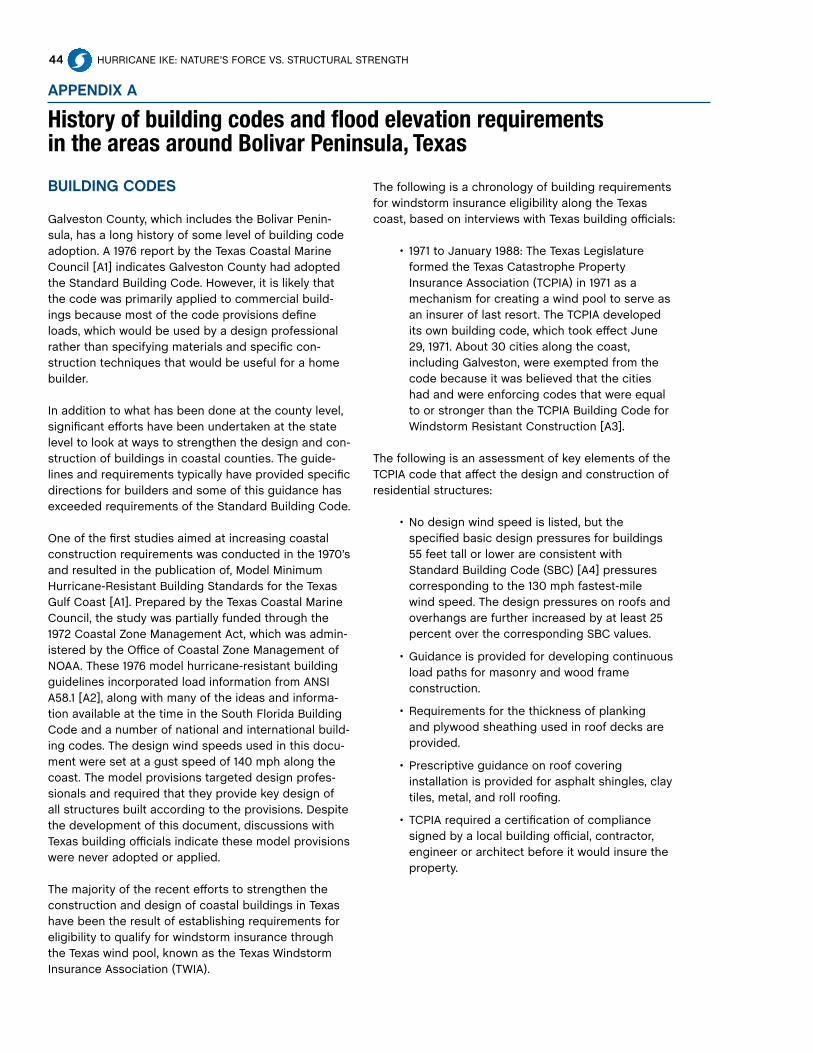
44 HURRICANE IkE: NATURE’S FORCE VS. STRUCTURAL STRENGTH
aPPendix a
History of building codes and flood elevation requirements in the areas around Bolivar Peninsula, Texas
BuildinG codeS
Galveston County, which includes the Bolivar Penin-sula, has a long history of some level of building code adoption. A 1976 report by the Texas Coastal Marine Council [A1] indicates Galveston County had adopted the Standard Building Code. However, it is likely that the code was primarily applied to commercial build-ings because most of the code provisions define loads, which would be used by a design professional rather than specifying materials and specific con-struction techniques that would be useful for a home builder.
In addition to what has been done at the county level, significant efforts have been undertaken at the state level to look at ways to strengthen the design and con-struction of buildings in coastal counties. The guide-lines and requirements typically have provided specific directions for builders and some of this guidance has exceeded requirements of the Standard Building Code. One of the first studies aimed at increasing coastal construction requirements was conducted in the 1970’s and resulted in the publication of, Model Minimum Hurricane-Resistant Building Standards for the Texas Gulf Coast [A1]. Prepared by the Texas Coastal Marine Council, the study was partially funded through the 1972 Coastal Zone Management Act, which was admin-istered by the Office of Coastal Zone Management of NOAA. These 1976 model hurricane-resistant building guidelines incorporated load information from ANSI A58.1 [A2], along with many of the ideas and informa-tion available at the time in the South Florida Building Code and a number of national and international build-ing codes. The design wind speeds used in this docu-ment were set at a gust speed of 140 mph along the coast. The model provisions targeted design profes-sionals and required that they provide key design of all structures built according to the provisions. Despite the development of this document, discussions with Texas building officials indicate these model provisions were never adopted or applied.
The majority of the recent efforts to strengthen the construction and design of coastal buildings in Texas have been the result of establishing requirements for eligibility to qualify for windstorm insurance through the Texas wind pool, known as the Texas Windstorm Insurance Association (TWIA).
The following is a chronology of building requirements for windstorm insurance eligibility along the Texas coast, based on interviews with Texas building officials:
• 1971toJanuary1988:TheTexasLegislatureformed the Texas Catastrophe Property Insurance Association (TCPIA) in 1971 as a mechanism for creating a wind pool to serve as an insurer of last resort. The TCPIA developed its own building code, which took effect June 29, 1971. About 30 cities along the coast, including Galveston, were exempted from the code because it was believed that the cities had and were enforcing codes that were equal to or stronger than the TCPIA Building Code for Windstorm Resistant Construction [A3].
The following is an assessment of key elements of the TCPIA code that affect the design and construction of residential structures:
• Nodesignwindspeedislisted,butthespecified basic design pressures for buildings 55 feet tall or lower are consistent with Standard Building Code (SBC) [A4] pressures corresponding to the 130 mph fastest-mile wind speed. The design pressures on roofs and overhangs are further increased by at least 25 percent over the corresponding SBC values.
• Guidanceisprovidedfordevelopingcontinuousload paths for masonry and wood frame construction.
• Requirementsforthethicknessofplankingand plywood sheathing used in roof decks are provided.
• Prescriptiveguidanceonroofcoveringinstallation is provided for asphalt shingles, clay tiles, metal, and roll roofing.
• TCPIArequiredacertificationofcompliancesigned by a local building official, contractor, engineer or architect before it would insure the property.

45
Ap
pend
ix A
HURRICANE IkE

46 HURRICANE IkE: NATURE’S FORCE VS. STRUCTURAL STRENGTH
aPPendix a (con’T)
History of building codes and flood elevation requirements in the areas around Bolivar Peninsula, Texas
From June 1, 1989, to Aug. 31, 1998; the Windstorm Resistant Construction Guide [A5] developed by the Texas Department of Insurance was used and sepa-rated the coastal area into two zones.
• Thezonesweredefinedastheareaseawardof the Intracoastal Waterway and inland of the Intracoastal Waterway.
• TheWindstorm Resistant Construction Guide provided a significant amount of prescriptive detail concerning a wide range of wind-resistant construction issues.
• Provisionswerebasedonthewindloadsinthe1973 edition of the Standard Building Code.
• Thecomponentandcladdingloadsofthatgeneration of SBC provisions were significantly lower than the values specified in modern wind standards. In terms of the design of component and cladding loads, these SBC design loads for roof edges and corners (typically the most critical roof zones corresponded to a 3-second gust wind speed of less than 90 mph using current code provisions.
• TheSBCbasicdesignpressurevaluescorrespond most closely to model building code values for a built-up area. Consequently, a home located along the coast or having a very open exposure should be designed for about 20 to 40 percent higher loads.
• BuildingscouldbeinsuredbyTCPIA,iftheywere built according to the guidelines that primarily targeted residential construction or if they were designed by a professional engineer to meet the requirements of the SBC 1973.
From Sept. 1, 1998, to Jan. 31, 2003; The Texas Wind-storm Insurance Association (TWIA) Building Code for Windstorm Resistant Construction [A6] was adopted and used by TDI to establish eligibility for wind pool insurance.
• Thiswasaprescriptivedocumentdevelopedbythe Texas Department of Insurance and based on wind load provisions of ASCE 7-93 [A7]. It included prescriptive requirements for the construction of wood and masonry structures.
• TheTWIAregulationsdividedthecoastalcounties into 3 zones:
• Seawardoftheinter-coastalwaterway;
• Inlandbetweentheinter-coastalwaterway and political or geographical boundaries that roughly corresponded to the 90 mph fastest-mile contour in ASCE 7-93; and
• Inlandofthepoliticalorgeographicalboundary that roughly corresponded to the ASCE 7-93 90 mph fastest-mile contour.
Applications
• TheTWIABuildingCodeforWindstormResistant Construction [A6] was applied to the first two zones;
• TheolderWindstormResistantConstruction Guide [A5] was applied to the third zone.
• ThebasicdesignwindspeedsusedfortheSeaward and Inland zones in the TWIA Building Code for Windstorm Resistant Construction are fastest-mile wind speeds of 100 mph and 95 mph, respectively.
• Thesecorrespondto3-secondgustbasic design wind speeds of 125 mph and 120 mph, respectively;
• andareingoodagreementwiththebasic design wind speeds shown in the current ASCE 7 standard.
• TheTWIABuildingCodeforWindstormResistant Construction provisions included requirements for windborne debris protection of all exterior openings, and the component and cladding loads were brought in line with the requirements of the ASCE 7-93 standard.
• Thewindbornedebrisprotectionrequirementsfor exterior openings essentially match both the testing and performance requirements of the South Florida Building Code, which were adopted in the mid 1990s and continue to be part of the Florida Building Code as the High Velocity Hurricane Zone requirements.
• Thewindbornedebrisprotectionrequirements were only applied to homes built in the zone located seaward of the Intracoastal Waterway. However,

47
Ap
pend
ix A
HURRICANE IkE
TDI required protection of all exterior openings (doors, windows, garage doors and skylights) regardless of whether or not the exterior opening had glazing.
• FromFeb.1,2003,toDec.31,2004;TDIadoptedthe 2000 International Residential Code (IRC) [A8] and the 2000 International Building Code (IBC) with Texas modifications to strengthen some provisions as the basis for eligibility of homes for wind pool insurance coverage. The 2000 IRC and IBC reference ASCE 7-98 [A9] for their wind load provisions.
• FromJan.1,2005,toDec.31,2007;TDIadoptedthe 2003 IRC [A10] and 2003 IBC with Texas modifications to strengthen some provisions as the basis for eligibility of homes for wind pool insurance coverage. The 2003 IRC and IBC reference ASCE 7-02 [A11] for their wind load provisions.
• SinceJan.1,2008topresent;TDIhasfollowedthe 2006 IRC [A12] and IBC with Texas modifications to strengthen some provisions as the basis for eligibility of homes for wind pool insurance coverage. The 2006 IRC and IBC reference ASCE 7-05 [A13] for their wind load provisions.
BuildinG codeS and older HomeS
Building code guidance, in terms of overall lateral and uplift loads imposed by the wind on structures built on the Bolivar Peninsula, remained essentially unchanged between the early 1970s and 1998. In 1998, the TWIA building code introduced significant-ly larger overall uplift and lateral loads for the homes built seaward of the inter-coastal waterway. This was due to the shift from the Standard Building Code to the ASCE 7 Standard as the basis for establishing wind loads. In addition, the TWIA building codes in force since Feb. 1, 2003, have explicitly accounted for dif-ferences between loads on homes built at sites with an open exposure and those located in the middle of a built up area. This is because both the IRC and IBC rely on ASCE 7 loads and design loads can be de-rived and prescriptive solutions are available for both exposures.
Prescriptive guidance and available strapping and specialty connectors were improved during the 1980s; particularly with the TWIA code adoption on Sept. 1, 1998. A critical question for older homes is whether they were being built using conventional norms or if builders actually strengthened the homes by tying the structures together in such a way that a continu-
ous load path was provided, which would hold the structure together and anchor it to the foundation. A study [A14] completed in 1990 by Texas Tech Univer-sity researchers and representatives of the Southern Building Code Congress International (SBCCI) found more than 50 percent of homes built in the City of Galveston, during various code eras, did not meet the requirements of the code in force at the time of construction.
The move to the TWIA Building Code for Windstorm Resistant Construction in September 1998 marked a major improvement in the wind load guidance with regard to building code requirements for cladding ele-ments. Further, the code’s initiation of opening protec-tion requirements provided additional protection for homes built seaward of the Intracoastal Waterway.
Ap
pend
ix A
reFerenceSA1 Texas Coastal Marine Council, (1976) Model Minimum
Hurricane-Resistant Building Standards for the Texas Gulf Coast
A2 American National Standards Institute, (1972) ANSI A58.1 Minimum Design Loads for Buildings and Struc-tures
A3 Texas Catastrophe Property Insurance Association, (1971) Building Code for Windstorm Resistant Con-struction
A4 Southern Building Code Congress International, Inc., (1973) Standard Building Code
A5 Texas Department of Insurance, (1989) Windstorm Re-sistant Construction Guide
A6 Texas Department of Insurance, (1998) Texas Wind-storm Insurance Association Building Code for Wind-storm Resistant Construction
A7 American Society of Civil Engineering, (1993) ASCE 7-93 Minimum Design Loads for Buildings and Structures
A8 International Code Council, (2000) International Resi-dential Code
A9 American Society of Civil Engineering, (1998) ASCE 7-98 Minimum Design Loads for Buildings and Structures
A10 International Code Council, (2003) International Resi-dential Code
A11 American Society of Civil Engineering, (2002) ASCE 7-02 Minimum Design Loads for Buildings and Struc-tures
A12 International Code Council, (2006) International Resi-dential Code
A13 American Society of Civil Engineering, (2005) ASCE 7-05 Minimum Design Loads for Buildings and Struc-tures
A14 James R. McDonald and Billy Manning, (1990) Effective-ness of Building Codes and Construction Practice in Reducing Hurricane Damage to Non-engineered Con-struction, Texas Tech University and Southern Building Code Congress International, Inc. Report.

48 HURRICANE IkE: NATURE’S FORCE VS. STRUCTURAL STRENGTH
The houses on the Bolivar Peninsula with Fortified…for safer living® designations were built to require-ments created when the program was first launched in October 2000. These requirements are a mixture of performance and prescriptive criteria. Subsequent to construction of the Bolivar Peninsula homes, IBHS adopted a land use policy and updated its design cri-teria; effectively, these changes now prohibit Fortified designations for homes built on barrier islands or low-lying land such as the Bolivar Peninsula, where surge is a significant risk.
IBHS recognizes that individual homes and commu-nities will continue to exist and be rebuilt on barrier islands, because absolute prohibitions on such devel-opment are not politically feasible in most cases. As a result, regardless of whether formal Fortified designa-tions are possible, it makes good public safety sense to encourage those who choose to build in such risky areas to utilize superior construction standards mod-eled after the Fortified program.
The original Fortified program basically picked the highest fastest-mile design wind speed in ASCE 7-93, a value of 110 mph, and used it as the basis for wind design. This corresponds to a 3-second gust wind speed of 130 mph and is comparable to the design wind speed for the Bolivar Peninsula.
An update to the Fortified criteria, published in late 2007, now requires a design wind speed equal to the ASCE 7 (3-second gust) wind speed plus 20 mph. In accordance with this update, the requirement for the Fortified design wind speed (3-second gust) on the Bolivar Peninsula would be 150 mph. The most widely used prescriptive high wind standard available during the time of the program’s develop-ment, which addressed both masonry and wood frame construction and contained guidance at the 110 mph fastest-mile or 130 mph peak 3-second gust level, was the one adopted by the Standard Building Code and promulgated through the SSTD 10 series of standards [24]. Homes constructed with continuous load paths similar to the approach followed in SSTD 10 have proven to be less vulnerable to structural damage in hurricanes. While the Fortified program used the SSTD 10-99 pre-scriptive structural guidance for much of its minimum construction criteria, the criteria targeting hurricane protection included the following requirements, all of which typically exceeded the SSTD 10-99 require-ments:
1. All roof decks must be fully sheathed using 40/20 rated panels with a minimum thickness of 19/32-inches. In most cases, SSTD 10-99 would allow 15/32-inch sheathing.
2. Roof sheathing to be attached using 8d ring shank (2 1/2-inches long by 0.120-inch diameter) nails at 4 inches on center for panels adjacent to a gable end and 6-inch spacing everywhere else.
a. This is similar to SSTD 10-99 requirements for the highest wind zone except that the 4-inch spacing is required over the entire length of the sheathing elements adjacent to the gable end. In contrast, SSTD 10-99 only requires the 4-inch spacing along the gable end wall or gable truss.
3. All wall sheathing must be 32/16 rated with a minimum thickness of 15/32-inches, and all exterior walls must be fully sheathed.
a. In many cases, SSTD 10-99 would allow thinner sheathing and only require the sheathing where it is needed to achieve the required shear resistance.
aPPendix B
Institute For Business & Home Safety’s Fortified…For Safer Living® Program
Performance criteria provide a design professional with guidance necessary to use engineering principles to calculate required strength of specific members, systems and connections, and then use this information to design a structure. Prescriptive criteria provide more of a “cookbook” approach to construction by instructing the designer or builder about what size members and what types of connections to use in particular situations. Prescriptive criteria are intended to produce a structure that meets performance requirements, and therefore, frequently are known as “deem to comply” solutions. This is because the building code body developing the prescriptive criteria has approved use of those criteria in lieu of detailed engineering design.
PerFormance vS. PreScriPTive

Ap
pend
ix B
49HURRICANE IkE
b. The 2007 Fortified update maintained the requirement that exterior walls be fully sheathed. Minimum wall sheathing thickness required for impact resistance is dependent upon the exterior finish covering: i.e. 1/2-inch is the minimum thickness with vinyl or aluminum siding and 7/16-inch is the minimum for brick veneer and stucco and for 1/2-inch thick wood or fiber cement siding.
4. A secondary water barrier must be installed to help keep water from flowing through cracks between roof sheathing elements when the roof cover is damaged. The 2007 Fortified update increased the options available for the types of secondary water barriers that can be used.
a. This is not required in SSTD 10-99.
5. All soffits and fascias must be able to resist minimum positive (upward or inward acting) pressures of 33 psf and negative (downward or outward acting) pressures of 43 psf as determined by the AAMA 1402-86 test standard.
a. SSTD 10-99 has no specific requirements for soffit or fascia loads or design except to point back to the Standard Building Code requirements.
b. The updated Fortified criteria now requires that soffits and fascias have a minimum design pressure rating (as determined by AAMA 1402-86) capable of resisting the component and cladding design wind pressures for the adjacent wall. This would result in generally higher
soffit design pressures for wind speeds of 130 mph (3 second gust) and greater.
6. The elevation of the building must be increased so that the lowest floor level or the level of the bottom of the horizontal structural elements of the lowest habitable floor of elevated structures is two feet above the BFE.
a. SSTD 10-99 is silent on elevation requirements, so it would default to the BFE at the site or the minimum elevation adopted by the local jurisdiction (sometimes one foot above the BFE).
b. The updated Fortified criteria now call for an increased elevation of three feet above the BFE, which is a one-foot increase.
7. Open foundations must be used in V zones and in Coastal A zones.
a. SSTD 10-99 does not address the selection of appropriate foundation systems. National Flood Insurance Program (NFIP) requirements would govern in order to be eligible for federal flood insurance.
b. The 2007 Fortified criteria update now requires that foundations must be designed for flood forces, as required by ASCE 24-05 “Flood Resistant Design and Construction”, for the Fortified design flood elevation of at least 3 feet above BFE.
Fortified homes that survived Hurricane Ike on the Bolivar Peninsula, Texas.

50 HURRICANE IkE: NATURE’S FORCE VS. STRUCTURAL STRENGTH
aPPendix c
Original IBHS code-plus Fortified criteria vs. eligibility requirements for homes seeking Texas Wind Pool Insurance
On June 29, 1971, the Texas Catastrophe Property Insurance Association (TCPIA) implemented the Building Code for Windstorm Resistant Construction (1971 TCPIA Building Code) [B1]. Following Hurricane Alicia, TCPIA and its successor, the Texas Windstorm Insurance Association (TWIA), implemented a much more comprehensive Building Code for Windstorm Resistant Construction (1988 TDI Windstorm Resistant Construction Guide) [B2] on Jan. 1,1988. This code was replaced in September 1998 by an updated version developed by TDI and based on ASCE 7-93 wind load provisions (1998 TWIA Building Code) [B3]. These codes all provided a variety of prescriptive alternatives that could be used to construct residential buildings along the Texas Coast.
In February 2003, TDI adopted the International Residential Code [B4] and the International Building Code [B5] as the basis for providing windstorm protection. These codes in turn refer to the American Forest & Paper Association’s Wood Frame Construction Manual (WFCM) [B6] and SSTD 10-99 [B7] for high wind design of residential buildings. The prescriptive guidelines in these various documents provided base requirements for residential construction to be eligible for insurance through the Texas Wind Pool. The following is an analysis of key elements of the wind-resistant construction prescriptive requirements in the Fortified program [B8, B9] and various Texas guidelines and code requirements.
Roof Sheathing • The1971TCPIABuildingCoderequiredeither
nominal 1-inch thick boards that were no more than 6-inches wide or 5/8-inch thick plywood.
• The1988TDIWindstormResistantConstructionGuide required nominal 5/8-inch thick sheathing (19/32-inch thick sheathing) seaward of the Intracoastal Waterway and nominal 1/2-inch thick sheathing (15/32-inch thick sheathing) inland of the Intracoastal Waterway.
• GivenIke’swindspeeds,theuseof15/32-inch sheathing as opposed to 19/32-inch
sheathing should not have affected the roof sheathing performance.
• Theserequirementsdidnotchangeinthe1998TWIA Building Code. With the introduction of the ICC based codes in 2003, the sheathing could have been as thin as 15/32-inch if SSTD 10-99 requirements were followed, but would have been 19/32-inch if the WFCM was followed.
•FortiFiedrequirementsvs.TexaS GuidelineS
• Intheseawardregion,thesheathingrequirements of the TCPIA and TWIA Building Codes, the WFCM and the Fortified program were the same. Only SSTD 10-99 would have allowed thinner sheathing in this region.
• InlandoftheIntracoastalWaterway,theTCPIA and TWIA Building Codes and both the WFCM and SSTD 10-99 allowed thinner sheathing than the Fortified program.
Roof Sheathing attachment • The1971TCPIABuildingCodedidnotcontain
any prescriptive requirements for roof deck attachment. The American Plywood Association fastening requirements for roof sheathing at that time would have allowed the use of 6d nails at 6-inch spacing along the edges of the sheathing and 12-inch spacing along intermediate members. It is likely that some builders would have used the 6d nails, but many would have substituted 8d nails at the same spacing.
• The1988TDIWindstormResistantConstructionGuide required 8d nails at 6 inches on center along the edges of sheathing panels and 12-inch spacing along intermediate support members.
• The1998TDIrequirementsleftthenailingpattern for sheathing in the middle of the roof at the same 6-inch spacing along panel edges and 12-inch spacing along interior supports; but, reduced the fastener spacing for sheathing within 4 feet of the perimeter of the roof and 4 feet on either side of a ridge to 4-inches along the edges of the panels and 6 inches along intermediate supports.

51HURRICANE IkE
Ap
pend
ix C
• TheWFCMwouldrequireattachmentofsheathing in the middle of the roof at 6-inch spacing along panel edges and 12-inch spacing along interior supports; but, reduced the fastener spacing for sheathing within 4 feet of the perimeter of the roof and 4 feet on either side of a ridge to 6 inches along the edges of the panels and 6 inches along intermediate supports.
• Thefastenerrequirementsforroofsheathingin SSTD 10-99 are similar to those in the WFCM except for two modifications. SSTD 10-99 requires a nail spacing of 4 inches on center at the gable endwall or gable truss and 8d ring shank nails would be required at fastener locations within 5 feet of a gable end for homes built seaward of the Intracoastal Waterway.
• Sincesheathingupliftcapacityisverynearly directly proportional to the fastener spacing along interior members, the 1998 TDI requirement change represented a doubling of the uplift resistance as compared with the 1988 TDI Windstorm Resistant Construction Guide for roof sheathing around the perimeter of the roof, where the highest wind loads tend to occur.
•FortiFiedrequirementsvs.TexaS GuidelineS
• Thelikelyupliftresistanceofroofsheathing installed between 1971 and 1988 would have ranged from a quarter to an eighth of the uplift capacity of the Fortified requirements, when wood structural panes were used, and about equal to or an even greater uplift capacity when board sheathing was used.
• The1989TDIWindstormResistantConstruction Guide, as well as the WFCM requirements, provided about one-quarter of the uplift capacity of the Fortified requirements, which used ring-shank nails to nearly double the uplift capacity as smooth shank nails.
• The1998TWIABuildingCodeandWFCMroof sheathing fastening requirements provided about half of the uplift capacity for perimeter sheathing and about one-quarter of the uplift capacity in the middle of the roof when compared to the Fortified program requirements.
• TheSSTD10-99fasteningrequirementsprovide the same uplift capacity as the Fortified requirements within 5 feet of
gable ends, half of the uplift capacity within 4 feet of eaves and ridges and one-quarter of the uplift capacity in the middle of the roof.
Wall Bracing (Shear Resistance)
• The1971TCPIABuildingCodedidnotprovideany specific requirements for construction of shear walls. Consequently, the lateral resistance to wind loads relied on conventional carpentry methods.
• The1989TDIWindstormResistantConstructionGuide initially allowed bracing to be provided by either let-in-braces or 1/2–inch sheathing. The let-in-braces were defined as nominal 1x4 wood structural members applied diagonally across the wall studs, where the studs were notched to allow the braces to be let into the faces of the studs and keeping the face of the braces flush with the outer edge of the wall studs.
• Ifwoodlet-in-braceswereused,two8dnails were to be used to attach them at each intersection with a stud or plate.
• If1/2-inchsheathingwasusedtoachieve the lateral bracing, it had to be continuous with any joints blocked, from the top of the top plate to the bottom of the sole plate and attached with nails at 6-inch spacing around the edges and 12-inch spacing along intermediate stud.
• Fastenersspecifiedforattachingwallsheathing were 6d nails for inland areas and 8d nails for seaward areas. One let-in-brace or 4-foot wide piece of sheathing was required for every 12 feet of exterior wall.
• By1997,theTDIWindstormResistantConstruction Guide provided three additional prescriptive options for achieving corner and wall bracing. These included a SBC approved metal let-in-style brace, diagonal wood board sheathing, and shear walls where the entire wall was sheathed with plywood or siding.
• Theplywoodorsidingminimumthickness was set at 3/8-inch and fastening of shear wall sheathing was specified as 8d nails at 6-inch spacing around the edges and 12 inches along intermediate members.
• AnchorageofshearwallsintheTCPIABuilding Code was specified as 1/2-inch
52 HURRICANE IkE: NATURE’S FORCE VS. STRUCTURAL STRENGTH
aPPendix c (con’T)
Original IBHS code-plus Fortified criteria vs. eligibility requirements for homes seeking Texas Wind Pool Insurance
anchor bolts with a maximum spacing of 6 feet for a one-story building and 4 feet for a two-story building.
• Anaddedrequirementwasthatanchorbolts had to be within 18 inches of ends or joints in sill or sole plates.
• The1998TWIABuildingCodeincludedshearwall construction and anchorage requirements that were similar to those in SSTD 10-99 with some simplifications.
• TheTWIAcodeintroducedforthefirsttimealong the Texas Coast the requirement that hold-down anchors be installed at wall corners to restrain uplift on the ends of the shear walls. The code did not require that the walls be fully sheathed, and basically called for what SSTD 10-99 refers to as Type II shear walls.
• Itisdifficulttoputnumericalvaluesontherelative strength of the shear resistance provided by the different requirements used over the years because of the wide latitude in design options for shear walls. However, in a general sense, shear resistance of walls built to the 1989 TCPIA Building Code are probably less than half as strong as shear walls built to the 1998 TWIA Building Code requirements.
•FortiFiedrequirementsvs.TexaS GuidelineS
• SSTD10-99,theWFCM,andFortifiedrequirements for shear walls would produce somewhat stronger and better anchored shear walls than those built to the TWIA Code.
Gable end Bracing • The1971TCPIABuildingCodedidnotcontain
any guidance for the construction or bracing of gable end walls. Consequently, conventional carpentry methods would have been used.
• The1989TDIWindstormResistantConstructionGuide contained requirements for installing two diagonal braces; between the ridge beam in a rafter system and the top plates of the two load bearing walls that run parallel to the ridge or a single diagonal brace from the ridge beam and to the middle of the top plate of the wall under the gable end.
• Thefirstapproachdidnothingtobracethe gable end wall, and the second provided minimal bracing of the middle of the wall below the gable end.
• The1998TWIACodeadoptedtheSSTD10-99requirements that balloon framing, which is continuous members from the floor to the roof, be used in gable ends.
• Ifplatformframingwasused,thegableend wall had to be braced using the ceiling diaphragm.
•FortiFiedrequirementsvs.TexaS GuidelineS
• Thespecificbracingrequirementsfortheplatform framing case were identical to those in SSTD 10-99, the WFCM, and the Fortified requirements.
• Houseswithgableendsthatwerebuiltprior to 1998 are likely to be relatively poorly braced and more susceptible to damage than those in houses built to the newer codes, which are consistent with the Fortified standards.
connections between Rafters at Ridges
• The1971TCPIABuildingCoderequiredcollarties between every pair of opposing rafters but provided no specifics on the lumber size or fasteners to be used.
• The1989TDIWindstormResistantConstructionGuide called for 1x6 wood collar ties on every pair of opposing rafters for homes built seaward of the Intracoastal Waterway and on every other pair of rafters for homes built inland of the Intracoastal Waterway.
• The1998TWIAcoderequiredcollartiesorover-the-top metal strapping on every other pair of opposing rafters for inland areas and on every pair of opposing rafters for areas seaward of the Intracoastal Waterway.
•FortiFiedrequirementsvs.TexaS GuidelineS
• SSTD10-99onlyrequired1x6woodcollarties on every third pair of opposing rafters, while the Fortified program requires 1x6 wood collar ties or metal straps over the ridge between every pair

Ap
pend
ix C
53HURRICANE IkE
of opposing rafters regardless of the location of the home.
• TheFortifiedprogramrequirementsareessentially the same as those that have been required along the Texas coast in areas seaward of the Intracoastal Waterway since the original TCPIA Building Code was adopted in 1971.
Roof-to-Wall connections and Load Path through Walls
• The1971TCPIABuildingCodestates,“Raftersshall be anchored to the wall plate by approved metal anchors attached to at least every other rafter or shall be otherwise anchored in an approved manner.”
• The1989TDIWindstormResistantConstructionGuide treats rafter and truss roof framing differently and provides separate guidance for wood frame and masonry wall construction.
• Forraftersonwoodframewalls,the1989TDI Windstorm Resistant Construction Guide required that metal straps with a minimum uplift capacity of 300 pounds be used to anchor every other rafter to both plates of a double top plate or to the stud below. A similar requirement was included for attaching wall studs to the top plates or rafter and to the sole plate.
• Thisprovidedthefirstcleardefinitionof a continuous load path for transmitting uplift loads from the roof all the way to the bottom of the walls.
• Threedifferentoptionswerepresented for connecting rafters to masonry walls. These include anchorage of every other rafter using straps rated at either 300-pound minimum capacity, if the attachment were made to a bolted on top plate, or 500-pound minimum capacity, if the attachment were made directly to the bond beam at the top of the wall.
• Trussdesignswererequiredtobecompleted by an engineer and a sealed truss certificate was required that provided information on the specified capacity of the connection between the trusses and the wall below. Different design loads were
specified for design of trusses for inland and seaward zones.
• The1998TWIAcoderequiredthateach rafter be connected to both members of the wall top plate using connectors with capacities listed in a Table in the code and that trusses be designed to resist the uplift determined using ASCE 7-93.
• Thelanguageusedtospecifytherequirements are similar for the seaward and inland areas but the loads were higher for the seaward areas.
•FortiFiedrequirementsvs.TexaS GuidelineS
• TheoriginalFortifiedcriteriarequiredstraps, which wrapped over the top of each rafter or truss end and had a minimum capacity of 1,345 pounds for framing spaced at 24-inches on center and 900 pounds for framing spaced at 16-inches on center.
• ThecapacityspecifiedintheFortifiedprogram is about 41/2 times higher than the 300-pound minimum specified in the 1989 TDI Windstorm Resistant Construction Guide for every other rafter connection. However, it is comparable to the uplift requirement for roof trusses with a 32-foot span and 2-foot spacing between trusses located seaward of the Intracoastal Waterway. For inland areas, the 1989 TDI Windstorm Resistant Construction Guide would require about a 30 percent lower uplift capacity as compared to the seaward locations. The capacity specified in the Fortified program was about twice as high as those listed in the 1998 TWIA Building Code for inland areas, when considering the uplift requirements for rafters installed on a roof with a span of 32 feet and rafter spacing of 2 feet, and about 30 percent higher than the uplift requirements for seaward areas.
• Forhomesbuiltpriorto1998thatutilizedrafter systems, the uplift resistance would likely be on the order of one-fifth to one-ninth of that of a Fortified designated home.

54 HURRICANE IkE: NATURE’S FORCE VS. STRUCTURAL STRENGTH
aPPendix c (con’T)
Original IBHS code-plus Fortified criteria vs. eligibility requirements for homes seeking Texas Wind Pool Insurance
• Iftrusseswereusedtoconstructtheroof structure, the design capacity against uplift would be much closer to the Fortified requirements, and it is unlikely that the differences would be large enough to affect the performance of these connections in a storm of Ike’s intensity.
• Similarly,homesbuiltwithraftersusing the uplift requirements specified in codes beginning with the 1998 TWIA Building Code, and the later ICC code requirements, should be close enough to the Fortified criteria that it would not affect the performance of these connections in a storm of Ike’s intensity.
Foundation Design • The1989TDIWindstormResistantConstruction
Guide contained specific information on the design of elevated foundations for coastal areas and differentiated the requirements depending on whether the site was (V zones) subjected to storm surge and waves or was located in areas (A zones) not subjected to these conditions. It also differentiated between cases where knee braces were acceptable and those where knee braces were not acceptable.
• Forpileswherekneebraceswereacceptable,the piles were only required to extend a distance into the ground equal to the distance above grade to the bottom of the lowest floor.
• Whenkneebraceswerenotacceptable,thepiles were required to extend 12 feet below mean sea level in V zones and 12 feet to 20 feet below grade (depending on soil type) in A zones.
• NFIPrequirementsforbreak-awaywallswere recognized, and it was noted that the walls and contents in storage areas enclosed by break-away walls could not be insured by the Texas Wind Pool.
• The1998TWIABuildingCodeprovidedaseriesof even more specific requirements for pile embedment depths through the use of tables and some specific minimum requirements.
• Inadditiontothetabulatedembedmentlengths,the code gives the following embedment requirements for piles in V zones:
• 5feetbelowmeansealevelinareaswitha base flood elevation of 10 feet or less.
• 10feetbelowmeansealevelinareaswith a base flood elevation greater than 10 feet.
• Forthefirstrowofstructuresfromthewater with piles in sand, the embedment depth listed above is to be increased by 4 feet to account for scour.
• Forstructuresotherthanthoseinthefirst row from the water with piles in sand, the embedment depth listed above is to be increased by 2 feet to account for scour.
•FortiFiedrequirementsvs.TexaS GuidelineS
• TheoriginalFortifiedcriteriarequiredopen foundations with continuous piles and that designs conform to the FEMA Coastal Construction Manual.
• Themainchangewasthatthebottomofthe lowest horizontal support member had to be at least 2-feet above the base flood elevation established by the NFIP.
Roof cover underlayment • The1988Guidelinesprovidedminimalguidance
for the installation of underlayments for shingle roof covering. It simply recommended the installation of a single layer of 15-pound felt when the roof slope was greater than 4:12 and two layers when the roof slope was less than 4:12. No specific guidance was given for the fastening of the felt except that a drawing indicated 2-inch side laps and 4-inch end laps.
• The1989TDIWindstormResistantConstructionGuide allowed the installation of a single layer of 15-pound felt when the roof slope was greater than 4:12 and required two layers, with specific instructions for how they should be installed, when the roof slope was less than 4:12. The only fastening requirement was a statement indicating that enough nails or staples should be installed to hold the felt in place until the shingles were installed. This type of guidance

Ap
pend
ix C
55HURRICANE IkE
is actually pretty consistent with what was in a number of other building codes at the time. The 1989 TCPIA Building Code did note that if aluminum caps were used, they should be attached with aluminum nails.
• The1998TWIABuildingCodeshiftedfromallowing 15-pound felt to requiring 30-pound felt as the minimum weight of felt material used in underlayments and added requirements that the felt be attached with certain size nails through 1-1/2-inch tin caps. It further required that the fasteners be installed at 12 inches on center along laps and a single row of fasteners at 24 inches on center along the center of the felt roll.
• WiththeintroductionoftheICC-basedcodes,15-pound felt once again was allowed as the underlayment and the fastening requirements (36 inches on center) were basically intended to keep the felt in place until shingles or tiles were installed.
•FortiFiedrequirementsvs.TexaS GuidelineS
• TheoriginalFortifiedcriteriarequiredthe installation of self-adhering polymer modified bitumen tape at least 4-inches wide over all roof panel joints.
• Overthetopofthis“secondarywaterresistance” it allowed use of a single layer of 30-pound felt or a double layer of 15-pound felt.
• Thefeltwastobeattachedwithlow profile roofing nails with load distribution disks or capped head nails spaced 6 inches along all laps and 12 inches in the interior of each strip of felt.
• Hotdippedgalvanizedfastenersarerequired when the home is within 3,000 feet of salt water.
Roof Cover • The1989TDIWindstormResistantConstruction
Guide specified that shingles were to be attached using the manufacturers specifications for high wind areas. If high wind specifications were not available, the shingles were to be attached with 6 nails. Guidelines were also included for a number of other types of roof cover materials.
• The1998TWIAcodelimitedshinglestothoseproducts listed by Underwriters Laboratories as
“wind resistant” by having passed the UL 997 standard. The approved products were to be applied using 6 nails per shingle. Other types of products were required to resist specified wind loads and have test reports and documentation on methods of installation submitted to TDI.
•FortiFiedrequirementsvs.TexaS GuidelineS
• TheoriginalFortifiedcriteriaforshingleroof installations required high wind rated shingle products installed with 6 nails per shingle and shingles around the perimeter were required to be attached using dabs of asphalt roofing cement.
• Thereislittledifferencebetweenshingleinstallation requirements between the 1989 TDI Windstorm Resistant Construction Guide, the TWIA 1998 Building Code or the Fortified criteria except for the adhesive added to anchor perimeter shingles in the Fortified criteria.
• Itshouldbenotedthattheadhesivestripbuilt into the shingles, which leads to adhesion of shingle tabs to the shingle below, was improved considerably during the 1990s and new test methods and standards were developed.
• Shingleswithhigherwindratingswereintroduced into the market place. One of the first steps towards establishing higher ratings of shingles was provided by testing to a Miami-Dade standard which used the ASTM D3161 test method with the wind speed modified to 110 mph.
• Shinglesmeetingthisteststandardhave been accepted for use in the Fortified program. More recently, a new test standard (ASTM D7158) has been developed and the new Fortified program would require shingles attaining an H rating under this standard (150 mph rating) to be used in the areas along the Texas Coast seaward of the Intracoastal Waterway.
Soffits and Ventilation • Theonlydiscussionofsoffitsandventilationin
the 1989 TDI Windstorm Resistant Construction Guide addressed the need to make sure that there was equal ventilation on opposite side of the roof eaves so that pressures were

56 HURRICANE IkE: NATURE’S FORCE VS. STRUCTURAL STRENGTH
aPPendix c (con’T)
Original IBHS code-plus Fortified criteria vs. eligibility requirements for homes seeking Texas Wind Pool Insurance
equalized in the attic. There was no discussion of requirements for attachment of the soffit materials.
• Theonlychangeinthe1998TWIAcodeinaddressing these issues was the addition of the requirement that turbine and ridge vents had to be installed in such a manner as to comply with the required wind loads. Test reports including methods of installation were required for these systems.
•FortiFiedrequirementsvs.TexaS GuidelineS
• TheoriginalFortifiedcriteriaincludedminimum design pressures for soffits as determined by the AAMA 1402-89 test standard and the soffit materials had to be installed according to the manufacturers’ recommendations for high-wind regions.
Windows and Doors • The1988guidelinesdiscussedtheneedto
attach window and door frames to adequately resist wind pressures; but did not provide specifics. The installation of shutters was not required, but the code did suggest that shutter products will protect from windborne debris while requiring that windows be capable of resisting wind pressures. The 1989 TDI Windstorm Resistant Construction Guide only addressed the anchorage of frames. It also provided some specific guidance on the minimum sizes and spacing of fasteners.
• The1998TWIABuildingCodemadeprogressin addressing windows and doors by providing positive and negative design pressures for windows and doors and adding requirements for protecting exterior openings from the impact of windborne debris. With the adoption of the ICC codes in 2003, protection of glazed openings was required in Inland I areas, while protection of all exterior openings was required in the seaward area.
•FortiFiedrequirementsvs.TexaS GuidelineS
• Theperformancecriteriaforopeningprotection have been essentially the same as that used by Miami-Dade County, Fla., which mirrors the Fortified criteria.
• TDIandMiami-Dadehavebothbeenusing the most stringent opening protection requirements for residential buildings adopted anywhere in the United States.
• TheoriginalFortifiedcriteriarequiredwind pressure and windborne debris impact protection for all glazed openings and added flashing and installation guidance to help minimize water intrusion around the frames of windows and doors.
• Thedebrisprotectionrequirementswereextended to include ASTM E1996 and SSTD 12 test protocols. Therefore, the performance criteria for the opening protection were not quite as high as in the TWIA 1998 Building Code.
reFerenceS:B1 Texas Catastrophe Property Insurance Association,
(1971) Building Code for Windstorm Resistant Con-struction
B2 Texas Department of Insurance, (1989) Windstorm Resistant Construction Guide
B3 Texas Department of Insurance, (1998) Texas Wind-storm Insurance Association Building Code for Windstorm Resistant Construction
B4 International Code Council, (2000) International Residential Code
B5 International Code Council, (2000) International Building Code
B6 American Forrest and Paper Association (1995) Wood Frame Construction Manual for One- and Two-Family Dwellings High Wind Edition
B7 Southern Building Code Congress International, Inc., (1999) SS TD 10-99 Standard for Hurricane Resistant Residential Construction
B8 Institute for Business & Home Safety (1995) Fortified . . . for safer living® Builders Guide
B9 Institute for Business & Home Safety (1997) Fortified . . . for safer living® Builders Guide Ver. 2.0


Institute for Business & Home Safety4775 E. Fowler Avenue, Tampa, FL 33617(813) 286-3400DisasterSafety.org
![Origin of the Hurricane Ike forerunner surgecoast.nd.edu/reports_papers/forerunner_2011GL047090.pdf2. Hurricane Ike Forerunner Observations [4] Two days prior to Ike’s landfall,](https://img.dokumen.tips/doc/110x75/5f77c490deecde5f0019f526/origin-of-the-hurricane-ike-forerunner-2-hurricane-ike-forerunner-observations.jpg)