Embed Size (px)
Citation preview
HUMZA WALI
HUMAN ROBOT COLLABORATION IN ASSEMBLY PROCESSES
Master of Science Thesis
Examiners: Prof. Minna Lanz Asst. Prof. Roel Pieters Examiner and topic approved on August 08, 2018
i
ABSTRACT
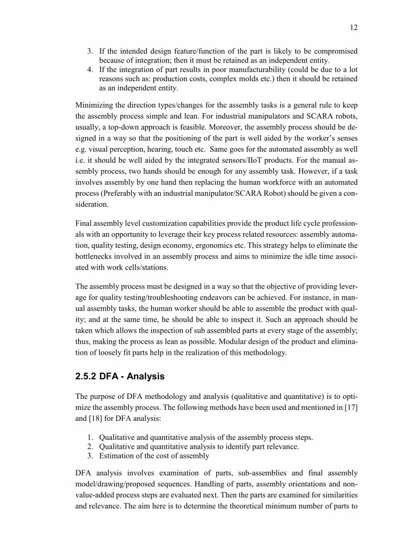
HUMZA WALI: Human Robot Collaboration in Assembly Processes Tampere University of technology Master of Science Thesis, 61 pages, 11 Appendix pages November 2018. Degree Programme in Automation Engineering, M.Sc. (Tech) Major: Fluid Power (Automation and Hydraulic Engineering). Minor: Life-Cycle Management and Engineering (Mechanical Engineering and In-dustrial Systems). Examiners: Prof. Minna Lanz, Ph.D. Asst. Prof. Roel Pieters, Ph.D. Keywords: Human Robot Collaboration (HRC), KONE Corporation, KUKA LBR iiwa, Design for Assembly (DFA) methodology, Switch Module Assembly, DIN rail assembly Human robot collaboration (HRC) in assembly processes, is a concept which aims to integrate the human workforce with the robots in a shared workspace. This is carried out to complement the human workforce to achieve key manufac-turing metrics e.g. efficiency, ergonomics, etc. Assembly of the switch module (DIN rail components’ assembly) was taken to be the product under investigation. Design of human robot collaborative assembly process was explored while con-sidering the following objectives and knowledge areas: Design for Assembly (DFA) methodology, rules for task assignment between the human worker and the robot, Identification and mitigation of process hazards, and trainable collabo-rative setups. A total of five DFA axioms were found to be relevant for the design of human robot collaborative assembly process. Task Assignments between the human and the robot was explored while considering the following objectives: Optimal assembly cycle times and workspace ergonomics. Three out of four phases of assembly process offered room for collaborative endeavors. The task assignments during these assembly phases ensured optimal cycle times and work space ergonomics. Risk assessment along with risk mitigation strategies were evaluated on the basis of ISO 12100. Hand guided frame teaching method-ology was used to train the collaborative setup. This enabled an operator friendly/oriented approach towards the design and implementation of collabora-tive assembly tasks. The obtained results ensured a reliable and industry scala-ble implementation of human robot collaborative assembly process.

ii
PREFACE
First of all, I would like to thank God for giving me strength and determination for un-
dertaking this thesis. I would also like to thank my thesis supervisors, Prof. Minna Lanz
and Asst. Prof. Roel Pieters, for their insight, input and guidance; throughout the research
and development process.
Being part of the Laboratory of Mechanical Engineering and Industrial Systems at Tam-
pere University of Technology, I learned and gained valuable knowledge regarding the
subject of Human Robot Collaboration in Assembly Processes. It was an honor and a
great learning experience to work with the UNITY project team. My utmost gratitude
towards the management of the case company, KONE Corporation, for providing support
and assistance during this thesis.
Lastly, I would like to thank my family for their unrelenting support during this defining
phase of my academic career.
Tampere, 02.11.2018
Humza Wali

iii
CONTENTS
1. INTRODUCTION .................................................................................................... 1
1.1 Background .................................................................................................... 1
1.2 The Problem Statement and Objectives ......................................................... 1
1.2.1 Research questions and objectives ................................................... 1
1.2.2 Limitations ....................................................................................... 1
1.2.3 Research and Development Process ................................................ 2
1.3 The Structure of the Thesis ............................................................................ 3
2. LITERATURE REVIEW ......................................................................................... 4
2.1 Historical Context – Industrial Revolutions ................................................... 4
2.2 Human Robot Collaboration .......................................................................... 5
2.3 Safety and risk assessment requirements for Human Robot Collaboration ... 8
2.3.1 Machinery Directive ........................................................................ 9
2.3.2 Standards Type A-B-C ..................................................................... 9
2.4 Assembly Stage Decomposition Model ....................................................... 10
2.5 Design for Assembly (DFA) Methodology .................................................. 11
2.5.1 Guidelines for DFA ........................................................................ 11
2.5.2 DFA - Analysis .............................................................................. 12
3. CASE STUDY: SWITCH MODULE ASSEMBLY .............................................. 16
3.1 Factory Floor Layout .................................................................................... 16
3.2 Product Description ...................................................................................... 17
3.3 Manual Assembly Process ........................................................................... 19
3.4 Human Robot Collaborative Assembly Process .......................................... 21
4. SYSTEM DESIGN - COLLABORATIVE OPERATION ..................................... 24
4.1 Layout Design .............................................................................................. 24
4.2 High Level Architecture – IIoT Products ..................................................... 26
4.3 COBOT Setup .............................................................................................. 26
4.3.1 Sensors and available control modes ............................................. 28
4.4 Risk Assessment ........................................................................................... 30
4.4.1 Identification of the use cases ........................................................ 31
4.4.2 Hazard identification ...................................................................... 32
4.4.3 Risk level estimation ...................................................................... 32
4.4.4 Risk mitigation ............................................................................... 33
5. APPLICATION - HUMAN ROBOT COLLABORATIVE ASSEMBLY ............. 36
5.1 Assembly Stage Decomposition Model ....................................................... 36
5.2 Product Design Analysis – DFA Methodology............................................ 39
5.2.1 Joining Methods ............................................................................. 39
5.2.2 Necessary parts .............................................................................. 40
5.2.3 Assembly Directions ...................................................................... 40
5.2.4 Available assembly stage customizations ...................................... 41
5.2.5 Quantifiable features of the product assembly ............................... 41
iv
5.3 Overview of the laboratory setup ................................................................. 42
5.4 Collaborative Assembly Tests ...................................................................... 44
5.4.1 First Test ........................................................................................ 45
5.4.2 Second Test .................................................................................... 46
5.4.3 Third Test ....................................................................................... 47
5.4.4 Operator oriented application design ............................................. 47
6. CONCLUSIONS ..................................................................................................... 54
7. FUTURE DEVELOPMENTS ................................................................................ 57
REFERENCES ................................................................................................................ 58
APPENDIX A: RISK ASSESSMENT WORKSHEETS
APPENDIX B: DFA ANALYSIS WORKSHEETS
v
LIST OF FIGURES
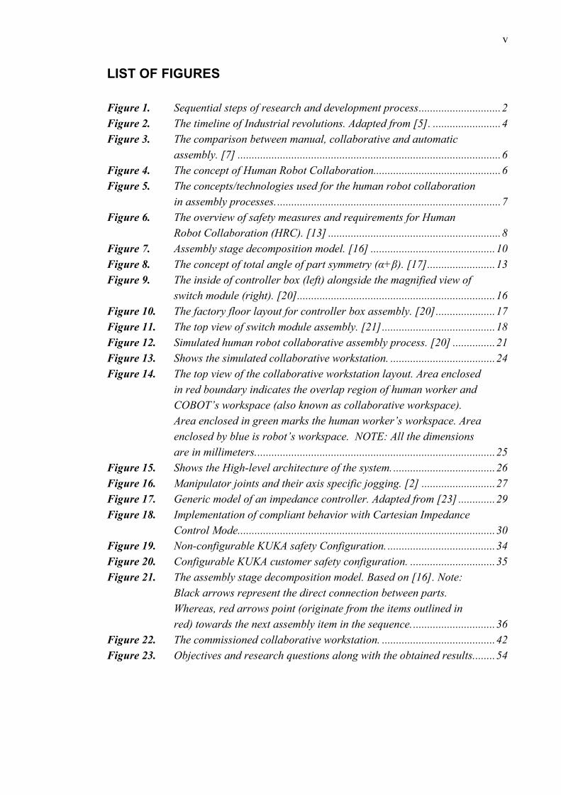
Figure 1. Sequential steps of research and development process ............................. 2
Figure 2. The timeline of Industrial revolutions. Adapted from [5]. ........................ 4
Figure 3. The comparison between manual, collaborative and automatic
assembly. [7] ............................................................................................. 6
Figure 4. The concept of Human Robot Collaboration............................................. 6
Figure 5. The concepts/technologies used for the human robot collaboration
in assembly processes. ............................................................................... 7
Figure 6. The overview of safety measures and requirements for Human
Robot Collaboration (HRC). [13] ............................................................. 8
Figure 7. Assembly stage decomposition model. [16] ............................................ 10
Figure 8. The concept of total angle of part symmetry (α+β). [17] ........................ 13
Figure 9. The inside of controller box (left) alongside the magnified view of
switch module (right). [20]...................................................................... 16
Figure 10. The factory floor layout for controller box assembly. [20] ..................... 17
Figure 11. The top view of switch module assembly. [21] ........................................ 18
Figure 12. Simulated human robot collaborative assembly process. [20] ............... 21
Figure 13. Shows the simulated collaborative workstation. ..................................... 24
Figure 14. The top view of the collaborative workstation layout. Area enclosed
in red boundary indicates the overlap region of human worker and
COBOT’s workspace (also known as collaborative workspace).
Area enclosed in green marks the human worker’s workspace. Area
enclosed by blue is robot’s workspace. NOTE: All the dimensions
are in millimeters. .................................................................................... 25
Figure 15. Shows the High-level architecture of the system. .................................... 26
Figure 16. Manipulator joints and their axis specific jogging. [2] .......................... 27
Figure 17. Generic model of an impedance controller. Adapted from [23] ............. 29
Figure 18. Implementation of compliant behavior with Cartesian Impedance
Control Mode........................................................................................... 30
Figure 19. Non-configurable KUKA safety Configuration. ...................................... 34
Figure 20. Configurable KUKA customer safety configuration. .............................. 35
Figure 21. The assembly stage decomposition model. Based on [16]. Note:
Black arrows represent the direct connection between parts.
Whereas, red arrows point (originate from the items outlined in
red) towards the next assembly item in the sequence. ............................. 36
Figure 22. The commissioned collaborative workstation. ........................................ 42
Figure 23. Objectives and research questions along with the obtained results........ 54
vi
LIST OF SYMBOLS AND ABBREVIATIONS
OS Operating System.
CEN Comité Européen de Normalisation, European Committee for Stand-
ardization.
CENELEC Comité Européen de Normalisation Électrotechnique, European
Committee for Electrotechnical Standardization.
ETSI European Telecommunications Standards Institute.
SME Small and medium-sized enterprises
R&D Research and Development.
ISO International Organization for Standardization.
ISO/TS International Organization for Standardization / Technical Specifica-
tion.
TM Total operation time.
CM Total operation cost.
NM Total of theoretical minimum part count.
ICT Information and Communication Technology Systems.
IIoT Industrial Internet of Things Products.
DFA Design for Assembly.
SCARA Selective Compliance Assembly Robot Arm or Selective Compli-
ance Articulated Robot Arm.
HRC Human Robot Collaboration.
EU European Union.
CE-marking Conformité Européenne, European Conformity: CE - marking signi-
fies that the product meets safety, health and environmental protec-
tion requirements laid out for European economic area by the Euro-
pean commission.
S/No. Serial Number
N/A Not Applicable.
TCP Tool center point.
COBOT A robot designed for direct interaction with a human within a defined
collaborative workspace. [1]
AMF Atomic Monitoring Function. [2]
min Minutes.
s Seconds.
mm Millimeters.
N Newton - Unit of force.
DIN Deutsches Institut für Normung

1
1. INTRODUCTION
1.1 Background
Human Robot Collaboration, a concept not alien to the industry of our time but develop-
ing at a dynamic rate; owing to the paradigms of the production processes. The idea nur-
tures as the physical entities like robots, machines etc. become sophisticated due to the
fusion of sensors, actuators, ICT systems etc. The goal being to integrate these intelligent
entities with the human workforce so that they complement each other in the production
processes; yet keeping it ergonomic. This is just a glimpse of the future of automation
which aims to integrate the technology with the humans and their society. It is termed as
the 4th Industrial revolution or Industry 4.0 [3].
1.2 The Problem Statement and Objectives
The purpose of this thesis is to analyze the human robot collaboration in assembly pro-
cesses alongside the key technologies used in it.
1.2.1 Research questions and objectives
The research questions and objectives are listed below:
1. What DFA methodology axioms are relevant for designing applications involving
human robot collaboration?
2. What are the rules for task allocation between humans and the robot?
3. What are the risks in human robot collaborative assembly process?
4. Is the human robot collaborative process reliable?
1.2.2 Limitations
To aid industrial deployment, open source and typical R&D software such as Robot op-
erating system, and MATLAB etc. weren’t utilized. These softwares require intensive
trainings regarding the knowledge areas of software engineering e.g. MATLAB script
programming language, and Ubuntu OS etc. Industrial stakeholders are potentially ex-
posed to heavy incurred costs as a result of these training activities. Apart from this, the
open source software also need extensive testing for stability and security issues. The
SMEs which serve as the backbone of the European economy [4] are reluctant to the use
of such softwares. Therefore, commercial software which are commonly used in the local
industry were utilized only. These are given as followed:
2
1. Use of Visual Components Software for layout planning and simulation.
2. Use of KUKA Sunrise.OS.
During the development of this thesis, external sensor systems (machine vision-based
safety and quality checking systems) were not utilized. Alternatively, the following IIoT
products were used:
1. Inherent input/output devices of the collaborative robot and its mobile base.
2. Industrial electric screwdriver with programmable controller.
This enabled the laboratory setup at Tampere University of Technology to correspond
with the presented scenario of the case study.
1.2.3 Research and Development Process
The research process, given in Figure 1, was used during the development of this thesis.
It is divided into 4 steps. It starts with process overview. Switch module’s assembly sim-
ulations and technical documents were utilized to prepare the case study. Then different
DIN rail assemblies were analyzed using Visual Components - 3D simulation software.
Figure 1. Sequential steps of research and development process
The product design analysis stage involves disintegration of the product. Assembly stage
decomposition model was prepared for the product under investigation. It was also ana-
lyzed using Design for Assembly (DFA) methodology tools and axioms.
Process
Overview
•Literature review
•Case study: Switch Module Assembly
•Development of collaborative assembly layouts and simulation of robotictasks
Product
Design
Analysis
•Product disintegration
•Assembly stage decomposition model
•DFA methodology
Commissioning
of the
Collaborative
Workstation
•Risk assessment and development of risk mitigation strategies
•Commissioning of COBOT setup and mapping of the required IIoT productsin KUKA SUNRISE.OS
Collaborative
Assembly
Experiments
•Different task assignments
•Hand guided frame teaching methodology
•Different speeds and compliant behaviour
3
During the third stage, risk assessment was carried out. At the latter parts of this stage,
KUKA Sunrise project was readied and tested by installing it on the robot controller. The
last stage involves testing of the collaborative assembly process for its reliability and
productivity.
1.3 The Structure of the Thesis
This thesis is divided into 7 chapters. These are explained in the following text.
1. The first chapter introduces the reader to the problem statement of the thesis and
its objectives.
2. The second chapter deals with the literature review. Industrial revolutions, human
robot collaboration, safety requirements and product analysis methodologies are
discussed in this chapter.
3. The third chapter presents the case study. This outlines the assembly requirements
of the switch module i.e. the product under investigation.
4. The fourth chapter discusses the design and planning of the human robot collab-
orative setup along with the necessary process details. This chapter includes: lay-
out design, high level system architecture and risk/hazard assessment.
5. The fifth chapter discusses the design and implementation of the human robot
collaborative assembly.
6. The sixth chapter gives the conclusions and results of this thesis.
7. The seventh chapter, which is the last one, discusses the future recommendations
and developments.
4
2. LITERATURE REVIEW
The literature review presented here focuses on the related concepts and technologies
which lead to the realization of human robot collaboration for the assembly of product
under investigation.
2.1 Historical Context – Industrial Revolutions
The concept of human robot collaboration is evolving due to emergence of various latest
technologies and knowledge areas like Internet of Things, Compliant robots etc. To delve
deeper into the topic, industrial revolutions and their technological impacts were, hence,
explored first.
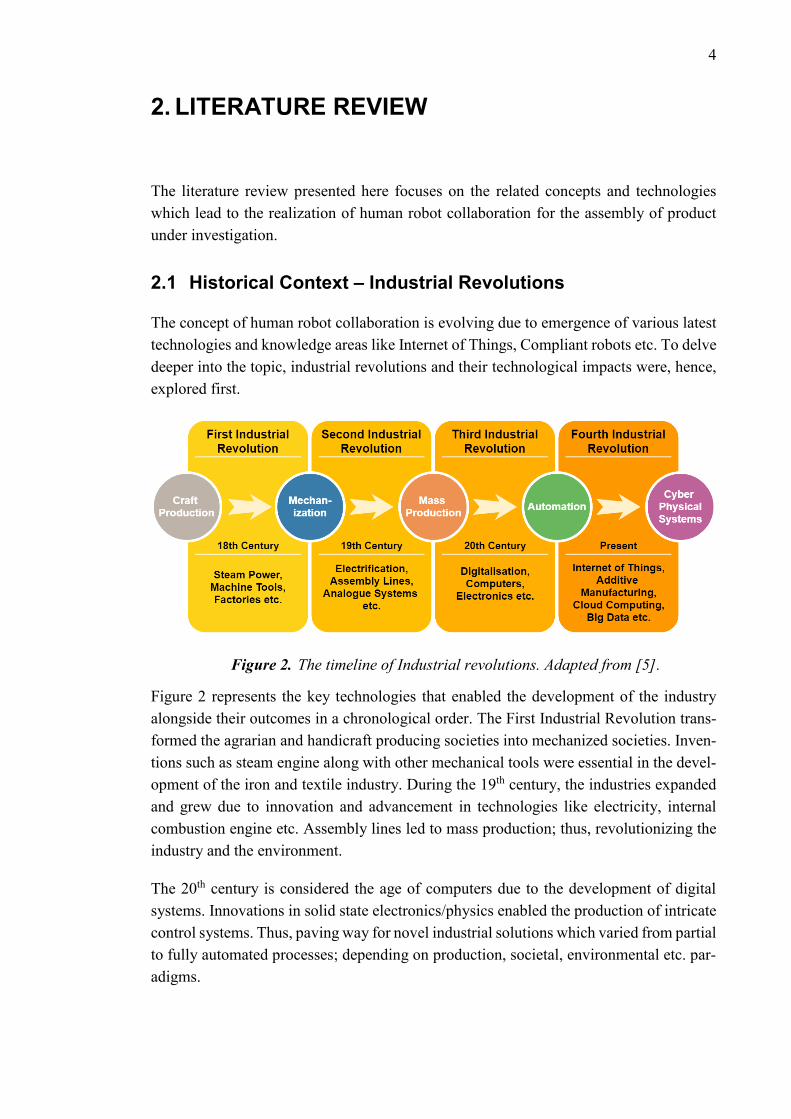
Figure 2. The timeline of Industrial revolutions. Adapted from [5].
Figure 2 represents the key technologies that enabled the development of the industry
alongside their outcomes in a chronological order. The First Industrial Revolution trans-
formed the agrarian and handicraft producing societies into mechanized societies. Inven-
tions such as steam engine along with other mechanical tools were essential in the devel-
opment of the iron and textile industry. During the 19th century, the industries expanded
and grew due to innovation and advancement in technologies like electricity, internal
combustion engine etc. Assembly lines led to mass production; thus, revolutionizing the
industry and the environment.
The 20th century is considered the age of computers due to the development of digital
systems. Innovations in solid state electronics/physics enabled the production of intricate
control systems. Thus, paving way for novel industrial solutions which varied from partial
to fully automated processes; depending on production, societal, environmental etc. par-
adigms.
5
The 21st century has seen the development of a lot of innovative technologies. These
technologies have emerged as market leaders and have also contributed towards a shifting
trend in R&D. These include additive manufacturing, cloud computing, trainable systems,
and complaint robots etc. to name a few. Such technologies have already started to usher
environmental changes globally. However, the impact on the industry worldwide is more
or less related to the empowerment of its workforce.
2.2 Human Robot Collaboration
Robots and IIoT devices are dominating the current world market. In the foreseeable fu-
ture their influence is more likely to alter life at work and home. Practices related to work,
health, environment, and safety etc. will transform with time to keep up with the increas-
ing human robot interaction. Human robot interaction has paved new horizons in the mar-
ket. Improvements have been seen in the delivered services alongside creation of new
jobs and diversification of current value chains. For instance, since HRC is a novel area
in the present market; therefore, technology transfer from R&D sector to the industry
offers a lot of room and potential for value adding activities. Furthermore, manufacturing
is a key value adding activity where usually the robots are deployed for large scale volume
production. However, Europe, being the global leader in production and supply of indus-
trial robotics, plans to deploy robots for small scale volume production. This is done to
maintain and nurture Europe’s production base, which is vital for its wealth generation
cycle. Usually, to keep the labor costs low, varied to full automation is carried out
throughout the production processes. These solutions are productive if the setup and the
running costs are low. But for the small-scale volume production, the automated solution
must offer high flexibility alongside low incurred costs. To achieve this, many novel so-
lutions have emerged in the market e.g. collaborative robots, trainable systems, and cus-
tomized interactive user interfaces etc. These solutions enable the placement of robot
alongside the human worker, during the manufacturing processes, without the need of
having typical safety fences. This concept is termed as Human Robot Collaboration and
it is explained in the following text. [6]
In human robot collaboration, the human and the robot work in partnership to complement
each other for achieving a common production/manufacturing goal. It is achieved by
providing specific set of capabilities. Usually, the robot assists the human worker in car-
rying out non-ergonomic tasks e.g. repetitive tasks, lifting heavy objects etc. On the other
hand, the human performs non-arduous tasks requiring human specific skills which are
otherwise not feasible to be carried out by the robot e.g. human supervision, planning etc.
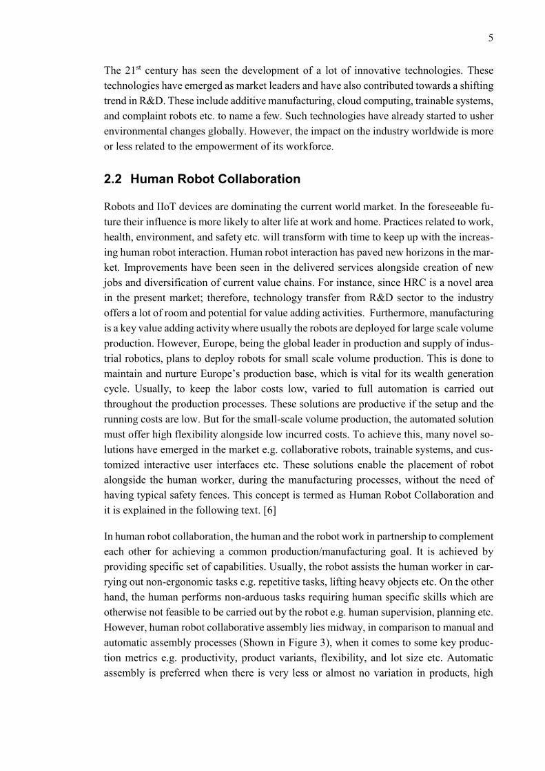
However, human robot collaborative assembly lies midway, in comparison to manual and
automatic assembly processes (Shown in Figure 3), when it comes to some key produc-
tion metrics e.g. productivity, product variants, flexibility, and lot size etc. Automatic
assembly is preferred when there is very less or almost no variation in products, high
6
productivity is required, and the commissioned setup remains unchanged unless it is re-
quired for non-value-added tasks like maintenance etc. Manual Assembly process, on the
contrary, is preferred when the lot sizes are low, productivity requirements are compara-
tively low, product variants are high, and the assembly process requires it to be highly
flexible. [7]
Figure 3. The comparison between manual, collaborative and automatic assembly.
[7]
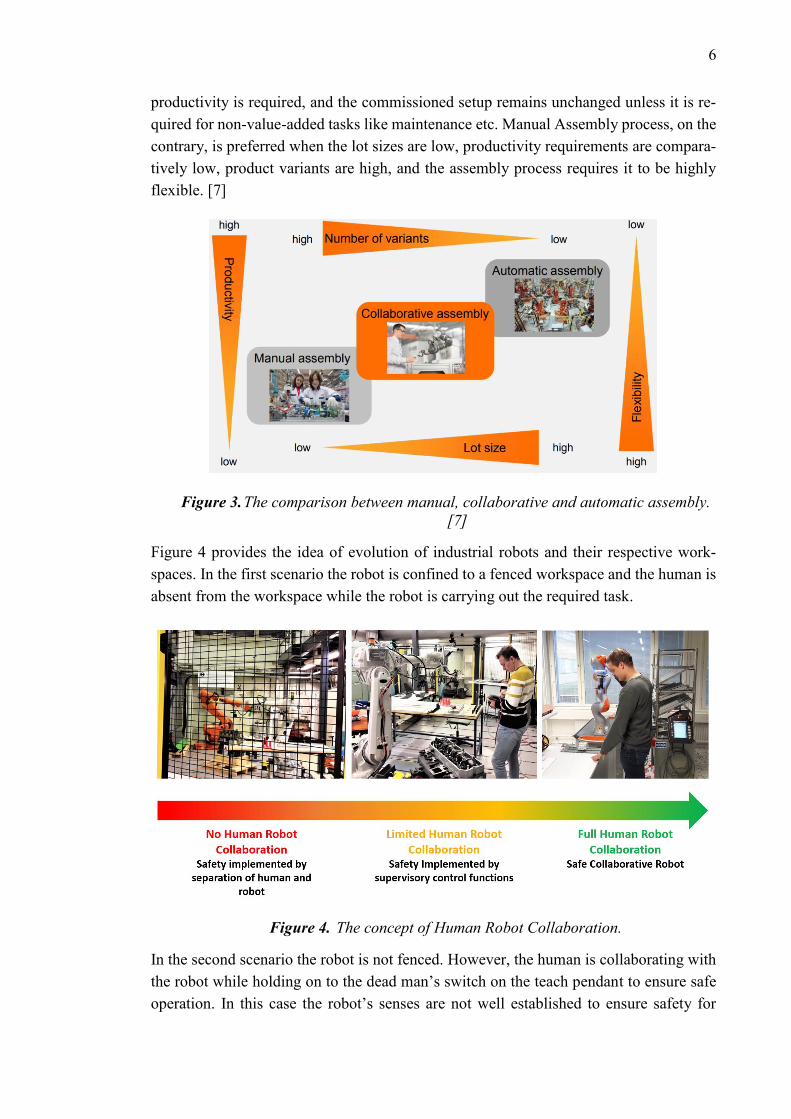
Figure 4 provides the idea of evolution of industrial robots and their respective work-
spaces. In the first scenario the robot is confined to a fenced workspace and the human is
absent from the workspace while the robot is carrying out the required task.
Figure 4. The concept of Human Robot Collaboration.
In the second scenario the robot is not fenced. However, the human is collaborating with
the robot while holding on to the dead man’s switch on the teach pendant to ensure safe
operation. In this case the robot’s senses are not well established to ensure safety for
7
humans and its surrounding work environment. Moreover, a dead man’s switch ensures
safe robot operations and is activated if the operator is debilitated. In the third scenario,
the robot utilizes its inherent sensors to ensure safety for the humans and its work envi-
ronment. Therefore, the human collaborates with the robot confidently without having
the need to hold on to the dead man’s switch.
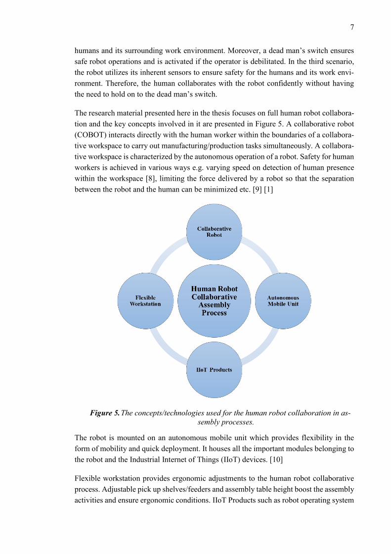
The research material presented here in the thesis focuses on full human robot collabora-
tion and the key concepts involved in it are presented in Figure 5. A collaborative robot
(COBOT) interacts directly with the human worker within the boundaries of a collabora-
tive workspace to carry out manufacturing/production tasks simultaneously. A collabora-
tive workspace is characterized by the autonomous operation of a robot. Safety for human
workers is achieved in various ways e.g. varying speed on detection of human presence
within the workspace [8], limiting the force delivered by a robot so that the separation
between the robot and the human can be minimized etc. [9] [1]
Figure 5. The concepts/technologies used for the human robot collaboration in as-
sembly processes.
The robot is mounted on an autonomous mobile unit which provides flexibility in the
form of mobility and quick deployment. It houses all the important modules belonging to
the robot and the Industrial Internet of Things (IIoT) devices. [10]
Flexible workstation provides ergonomic adjustments to the human robot collaborative
process. Adjustable pick up shelves/feeders and assembly table height boost the assembly
activities and ensure ergonomic conditions. IIoT Products such as robot operating system
8
(software), gripper system, external sensors, and actuators etc. exchange data via dedi-
cated field buses. [5]
When the human and the robot are collaborating in a shared collaborative workspace,
then the human can have two types of contacts with a robot. It can deliver static and
dynamic forces to the human body. According to [11], these are of two types and given
next:
1. Transient Contact
2. Quasi-Static Contact
Transient Contact is a type of contact between the human and the robot where the human
body is not clamped in-between the robot’s structure and the workstation. It can retract
and recoil after the contact. However, in case of Quasi-Static contact, the human worker’s
body part is clamped in between the moving/stationary part of the robot or its work cell.
The human is unable to retract and recoil. These contacts pose significant risks to the
robot and its environment. To mitigate these hazards different strategies could be adopted
e.g. use of vision-based safety systems [8], and active compliance of the robot etc. How-
ever, if the risk mitigation strategies are not applied carefully then it could result in an
increase in the overall entropy of the process [12]. The same applies to the case of robot
motion planning.
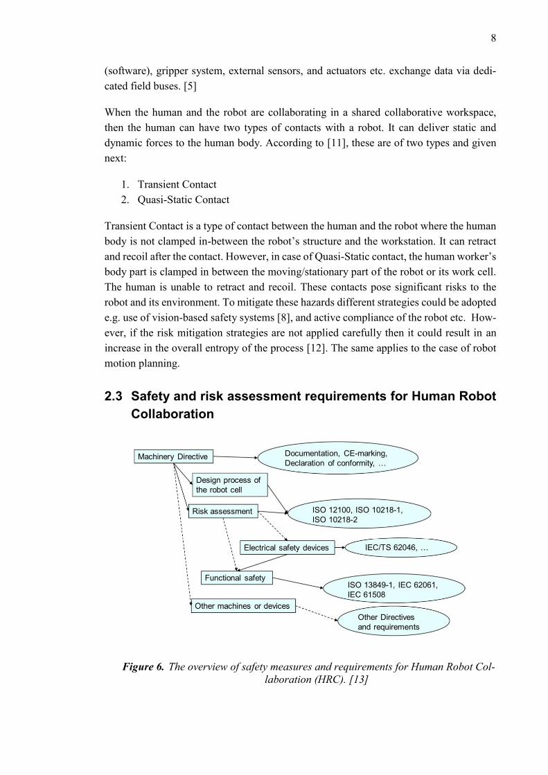
2.3 Safety and risk assessment requirements for Human Robot
Collaboration
Figure 6. The overview of safety measures and requirements for Human Robot Col-
laboration (HRC). [13]
9
A technical report presented by [13] gives an overview of the related standards and direc-
tives for safe robot operations and these are schematically presented in Figure 6. Further
explanation to the subject is given in the following text.
2.3.1 Machinery Directive
According to [14] a directive is defined as, “a legislative act that sets out a goal that all
EU countries must achieve.” Therefore, it can be stated that the European Machinery
Directive 2006/42/EC gives the necessary regulations regarding the health and safety re-
quirements for a new machinery to be placed in the EU market. It ensures free movement
of the machinery in the EU market. It also aims at providing maximum protection to EU
residents and its industrial workforce. Key activities relating to the use of machinery di-
rective are: risk assessment, preparation of technical manuals and instructions, CE-mark-
ings at the machines, declaration of conformity documents (a declaration specifying the
responsibility of design) etc. National laws (e.g. Finnish laws) regarding machinery,
which are obligatory to follow, are defined according to the machinery directive.
This directive is further explained by the Harmonized Standards. These are developed on
request of European commission by recognized European standards organizations such
as: CEN, CENELEC, ETSI etc. The use of a harmonized standard is intentional, and it
aims to give valid solutions within its scope.
Alongside harmonized standards, the machinery directive also refers to other standards
and technical specifications such as ISO 12100, ISO/TS 15066 etc. to make machines and
their operations safe.
2.3.2 Standards Type A-B-C
As per the definition of [15], Type-A standards are the basic safety standards which give
basic concepts, principles for design and general aspects that are applicable to a machin-
ery. Examples for this type are: ISO 12100 – Risk Assessment, IEC 61508 – Functional
Safety, etc.
As per the definition of [15], Type-B standards give generic safety guidelines and these
deal with one safety aspect or one type of safeguard which can be used across a wide
range of machinery. Examples for this type are: ISO 13849 – Safety of machinery part 1
and 2, ISO 11161 – Integrated manufacturing systems etc.
As per the definition of [15], Type-C standards provide detailed safety guidelines for a
particular machine or group of machines. These are also termed as individual safety stand-
ards. Examples for this type are: ISO 10218-1 – Robot, ISO 10218-2 – Robot system/cell,
ISO/TS 15066 – Collaborative Robots.
10
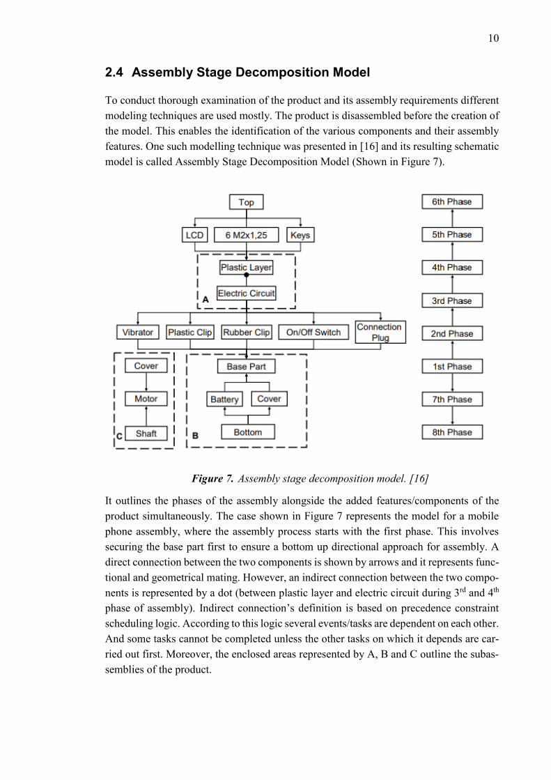
2.4 Assembly Stage Decomposition Model
To conduct thorough examination of the product and its assembly requirements different
modeling techniques are used mostly. The product is disassembled before the creation of
the model. This enables the identification of the various components and their assembly
features. One such modelling technique was presented in [16] and its resulting schematic
model is called Assembly Stage Decomposition Model (Shown in Figure 7).
Figure 7. Assembly stage decomposition model. [16]
It outlines the phases of the assembly alongside the added features/components of the
product simultaneously. The case shown in Figure 7 represents the model for a mobile
phone assembly, where the assembly process starts with the first phase. This involves
securing the base part first to ensure a bottom up directional approach for assembly. A
direct connection between the two components is shown by arrows and it represents func-
tional and geometrical mating. However, an indirect connection between the two compo-
nents is represented by a dot (between plastic layer and electric circuit during 3rd and 4th
phase of assembly). Indirect connection’s definition is based on precedence constraint
scheduling logic. According to this logic several events/tasks are dependent on each other.
And some tasks cannot be completed unless the other tasks on which it depends are car-
ried out first. Moreover, the enclosed areas represented by A, B and C outline the subas-
semblies of the product.
11
2.5 Design for Assembly (DFA) Methodology
Design for assembly is a concept which aims to facilitate the industrial workforce in de-
signing/planning the assembly processes with maximum achievable production/manufac-
turing metrics such as: efficiency, economy, ergonomics etc. However, in practice, usu-
ally a compromise is made among these key metrics. [17] [18] [19]
2.5.1 Guidelines for DFA
DFA, simply put, aims to reduce the number of parts; thereby, simplifying the assembly
process and reducing the timings involved in it. Moreover, DFA methodology could be
better understood by the axioms identified from [17] and [18]. And these are given below:
1. Simplification of the joining methods.
2. Reduction of parts.
3. Minimizing the assembly directions.
4. Availability of options for modification/customization at the final assembly level.
5. Testable entities.
Decreasing the number of mechanical fasteners such as bolts, screws etc. in a product can
ease the assembly process significantly by bringing down the part variability. Less num-
ber of parts and reduced variation leads to simplification; thus, reducing potential mis-
takes and unnecessary confusions. With this approach the assembly process design be-
comes lean as the number of tool changes are reduced. Space issues which arise due to
the use of tools in the assembly process, as they themselves consume a considerable
amount of space on the assembly table/station and around the product, can be eliminated
by simplifying the joining techniques. However, the joining methods should be designed
in a way so that the product can be easily analyzed using qualitative and quantitative
techniques. These analyses help the development of product and its life cycle.
Reduction of parts is a good strategy to simplify the assembly process. This approach
saves the time in almost all the phases of production processes; such as: planning, execu-
tion and monitoring/quality checks. The process of material handling and replenishment
of the feeders becomes more simplified. As the individual parts have various costs asso-
ciated with them, therefore, reduction of parts leads to an overall cost reduction of the
final assembled product. A good design strategy is to combine the individual parts to-
gether into chunks at every stage before the final assembly stage. Unless the reasons stated
next are to be satisfied, a good practice would be to eliminate the part altogether or it
should be integrated together with other similar parts. The reasons for part retention are:
1. The part moves with respect to other parts and these respective movements cannot
be generated through the material properties or any other known methods.
2. Objectives related to the order of assembly and maintainability/service of the
product require the part to remain as an independent entity.
12
3. If the intended design feature/function of the part is likely to be compromised
because of integration; then it must be retained as an independent entity.
4. If the integration of part results in poor manufacturability (could be due to a lot
reasons such as: production costs, complex molds etc.) then it should be retained
as an independent entity.
Minimizing the direction types/changes for the assembly tasks is a general rule to keep
the assembly process simple and lean. For industrial manipulators and SCARA robots,
usually, a top-down approach is feasible. Moreover, the assembly process should be de-
signed in a way so that the positioning of the part is well aided by the worker’s senses
e.g. visual perception, hearing, touch etc. Same goes for the automated assembly as well
i.e. it should be well aided by the integrated sensors/IIoT products. For the manual as-
sembly process, two hands should be enough for any assembly task. However, if a task
involves assembly by one hand then replacing the human workforce with an automated
process (Preferably with an industrial manipulator/SCARA Robot) should be given a con-
sideration.
Final assembly level customization capabilities provide the product life cycle profession-
als with an opportunity to leverage their key process related resources: assembly automa-
tion, quality testing, design economy, ergonomics etc. This strategy helps to eliminate the
bottlenecks involved in an assembly process and aims to minimize the idle time associ-
ated with work cells/stations.
The assembly process must be designed in a way so that the objective of providing lever-
age for quality testing/troubleshooting endeavors can be achieved. For instance, in man-
ual assembly tasks, the human worker should be able to assemble the product with qual-
ity; and at the same time, he should be able to inspect it. Such an approach should be
taken which allows the inspection of sub assembled parts at every stage of the assembly;
thus, making the process as lean as possible. Modular design of the product and elimina-
tion of loosely fit parts help in the realization of this methodology.
2.5.2 DFA - Analysis
The purpose of DFA methodology and analysis (qualitative and quantitative) is to opti-
mize the assembly process. The following methods have been used and mentioned in [17]
and [18] for DFA analysis:
1. Qualitative and quantitative analysis of the assembly process steps.
2. Qualitative and quantitative analysis to identify part relevance.
3. Estimation of the cost of assembly
DFA analysis involves examination of parts, sub-assemblies and final assembly
model/drawing/proposed sequences. Handling of parts, assembly orientations and non-
value-added process steps are evaluated next. Then the parts are examined for similarities
and relevance. The aim here is to determine the theoretical minimum number of parts to
13
reduce the actual part count and minimize the stages of assembly. These tasks are carried
out in the future redesign processes. Evaluation and estimation of costs involved in the
assembly processes are critical in the decision-making process of assembly task design.
DFA analysis (work sheet sample shown in Table 1) involves some terminologies which
are described next in this chapter:
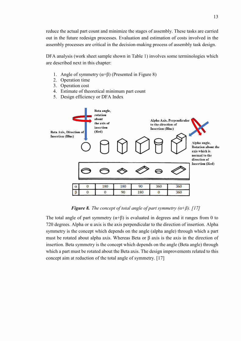
1. Angle of symmetry (α+β) (Presented in Figure 8)
2. Operation time
3. Operation cost
4. Estimate of theoretical minimum part count
5. Design efficiency or DFA Index
Figure 8. The concept of total angle of part symmetry (α+β). [17]
The total angle of part symmetry (α+β) is evaluated in degrees and it ranges from 0 to
720 degrees. Alpha or α axis is the axis perpendicular to the direction of insertion. Alpha
symmetry is the concept which depends on the angle (alpha angle) through which a part
must be rotated about alpha axis. Whereas Beta or β axis is the axis in the direction of
insertion. Beta symmetry is the concept which depends on the angle (Beta angle) through
which a part must be rotated about the Beta axis. The design improvements related to this
concept aim at reduction of the total angle of symmetry. [17]
14
The worksheet template for DFA analysis. [18] [17]
C1 C2 C3 C4 C5 C6 C7 C8 C9 C10
NA
ME
OF
TH
E P
RO
DU
CT
:
PA
RT
ID:
To
tal A
ng
le o
f S
ym
metr
y (
α+
β),
Deg
ree
s
No
. o
f ti
mes t
he o
pe
rati
on
is c
arr
ied
ou
t co
nse
cu
tively
Tw
o-d
igit
Man
ual H
an
dlin
g c
od
e
Man
ual H
an
dlin
g T
ime
pe
r p
art
Tw
o-d
igit
man
ual in
se
rtio
n c
od
e
Man
ual in
sert
ion
tim
e p
er
part
Op
era
tio
n t
ime,
Se
co
nd
s (
𝒕 𝒎)
Op
era
tio
n c
ost,
Eu
ros (
𝒄𝒎
)
Esti
mate
of
theo
reti
cal m
inim
um
part
co
un
t
Total
DF
A In
dex =
𝑡𝑚
,𝑚𝑖𝑛
×𝑁
𝑀
𝑇𝑀
=
TM CM NM
The operation time (𝑡𝑚) combines all the timings related to an individual part. These
usually involve the handling and insertion timings. Summation of the individual part op-
eration times gives the total time of operation referred to as TM in Table 1.
Similarly, operation cost (𝑐𝑚) combines all the costs associated with the individual part.
The costs are usually evaluated depending on the material handling technique and the
method of insertion utilized in the assembly task. Summation of the individual part oper-
ation costs gives the total cost of operation referred to as CM in Table 1.
15
Theoretical minimum part count is the classification-based value evaluated from the anal-
ysis of individual parts (of the final assembly). This analysis is based on the correspond-
ence/symmetry in physical, functional etc. properties of the sub-assembly parts. It could
also be based on the similarity of an operation e.g. similar fastening method, similar feed-
ing method etc.
Design efficiency or DFA index is a percentage measure of how convenient it is to as-
semble a product and it is given by:
𝐷𝐹𝐴𝐼𝑛𝑑𝑒𝑥 = 𝑡𝑚,𝑚𝑖𝑛 ×𝑁𝑀
𝑇𝑀× 100% → (1)
Whereas, the variables used in this formula are described in Table 2.
Description of variables used in computation of DFA index. [17]
Variable Explanation
tm,min The basic assembly time (handling and insertion) of the part having minimum
value. It is taken as 3 s on average.
TM Total operation time for the assembly in s.
NM Total of theoretical minimum part count.
DFAIndex Also known as the design efficiency. Rule of thumb suggests this value to be
< 60%
16
3. CASE STUDY: SWITCH MODULE ASSEMBLY
KONE Corporation, a world leader in the production of elevators and escalators, like all
other industrial giants is exploring the field of full human robot collaboration. The human
robot collaborative process was showcased as a 3D simulation in a seminar held in Espoo,
Finland on March 07, 2018.
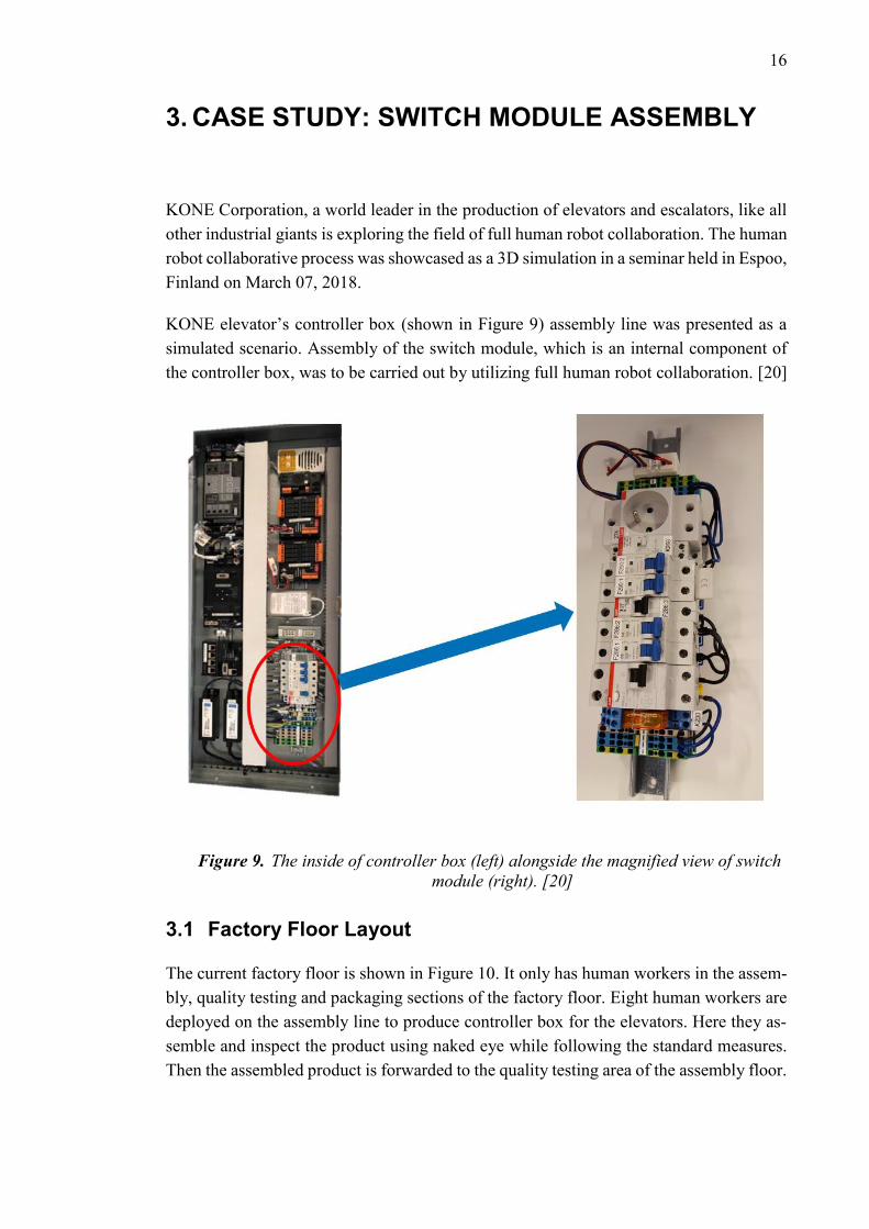
KONE elevator’s controller box (shown in Figure 9) assembly line was presented as a
simulated scenario. Assembly of the switch module, which is an internal component of
the controller box, was to be carried out by utilizing full human robot collaboration. [20]
Figure 9. The inside of controller box (left) alongside the magnified view of switch
module (right). [20]
3.1 Factory Floor Layout
The current factory floor is shown in Figure 10. It only has human workers in the assem-
bly, quality testing and packaging sections of the factory floor. Eight human workers are
deployed on the assembly line to produce controller box for the elevators. Here they as-
semble and inspect the product using naked eye while following the standard measures.
Then the assembled product is forwarded to the quality testing area of the assembly floor.
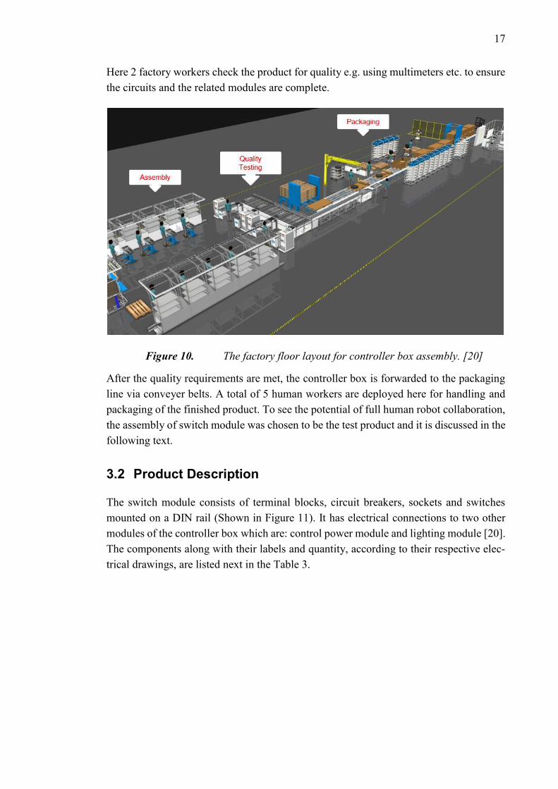
17
Here 2 factory workers check the product for quality e.g. using multimeters etc. to ensure
the circuits and the related modules are complete.
Figure 10. The factory floor layout for controller box assembly. [20]
After the quality requirements are met, the controller box is forwarded to the packaging
line via conveyer belts. A total of 5 human workers are deployed here for handling and
packaging of the finished product. To see the potential of full human robot collaboration,
the assembly of switch module was chosen to be the test product and it is discussed in the
following text.
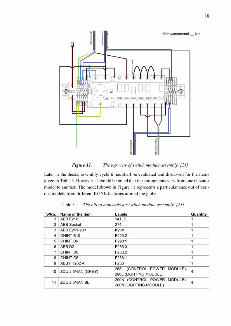
3.2 Product Description
The switch module consists of terminal blocks, circuit breakers, sockets and switches
mounted on a DIN rail (Shown in Figure 11). It has electrical connections to two other
modules of the controller box which are: control power module and lighting module [20].
The components along with their labels and quantity, according to their respective elec-
trical drawings, are listed next in the Table 3.
18
Figure 11. The top view of switch module assembly. [21]
Later in the thesis, assembly cycle times shall be evaluated and discussed for the items
given in Table 3. However, it should be noted that the components vary from one elevator
model to another. The model shown in Figure 11 represents a particular case out of vari-
ous models from different KONE factories around the globe.
The bill of materials for switch module assembly. [21]
S/No. Name of the item Labels Quantity
1 ABB E216 141: S 1
2 ABB Socket 274 1
3 ABB E251-230 K268 1
4 CHINT B10 F290:2 1
5 CHINT B6 F290:1 1
6 ABB D2 F286:3 1
7 CHINT D6 F286:2 1
8 CHINT C6 F286:1 1
9 ABB FH202 A F286 1
10 ZDU 2.5/4AN (GREY) 268L (CONTROL POWER MODULE),
286L (LIGHTING MODULE) 4
11 ZDU 2.5/4AN BL 290N (CONTROL POWER MODULE),
286N (LIGHTING MODULE) 4
19
12 ZPE 2.5/4AN (GREEN) PE1 (CONTROL POWER MODULE),
PE (LIGHTING MODULE) 4
13 DIN rail N/A 1
14 Wire Set
KM796121G12106,
KM51042524G14,
KM51062820G10135
3
15 Labels N/A 21
3.3 Manual Assembly Process
Currently, according to [21], the assembly tasks are being carried out by the human work-
ers. The quality control at this stage (assembly line) is carried out by visual inspection i.e.
using naked eye. Moreover, there is one human worker per workstation for assembly task.
The assembly steps are given below:
1. Clamping the DIN rail onto the assembly table.
2. One by one placing the components onto the DIN rail in the order given in Figure
9. The order of assembly could be either way from left to right and vice versa.
3. Making electrical connections by utilizing the provided set of wires and jumpers.
At this stage, designated screw drivers are used for securing the wires into the
terminals.
4. Placing the respective labels on the DIN rail assembled components.
5. The switch module assembly is now complete.
This module can now be forwarded to the next work station or retained at the same work
station for integration with other modules such as control power module, lighting module
etc. The assembly cycle time for the switch module, shown in Figure 11, is around
11.5min. However, it only takes 3.5 - 4 min to complete the assembly of other individual
modules (control power module, lighting module, etc.) of the controller box. Thus, it can
be said that the sub assembly of the switch module is the bottleneck in the assembly pro-
cess of controller box and has the highest cycle time of 11.5mins. [20]
Next the Takt time is evaluated according to different customer demands. Takt time de-
termines the required speed with which an assembly task must be carried out to keep up
with the customer demand. It is the ratio of total available production time to the average
customer demand. [20]
Takt Time is given by:
𝑇𝑎𝑘𝑡 𝑇𝑖𝑚𝑒 =𝑇𝑜𝑡𝑎𝑙 𝐴𝑣𝑎𝑖𝑙𝑎𝑏𝑙𝑒 𝑃𝑟𝑜𝑑𝑢𝑐𝑡𝑖𝑜𝑛 𝑇𝑖𝑚𝑒
𝐴𝑣𝑒𝑟𝑎𝑔𝑒 𝐶𝑢𝑠𝑡𝑜𝑚𝑒𝑟 𝐷𝑒𝑚𝑎𝑛𝑑→ (2)
The available production time per day and three different customer demands, as presented
in [20], are given next in Table 4:
20
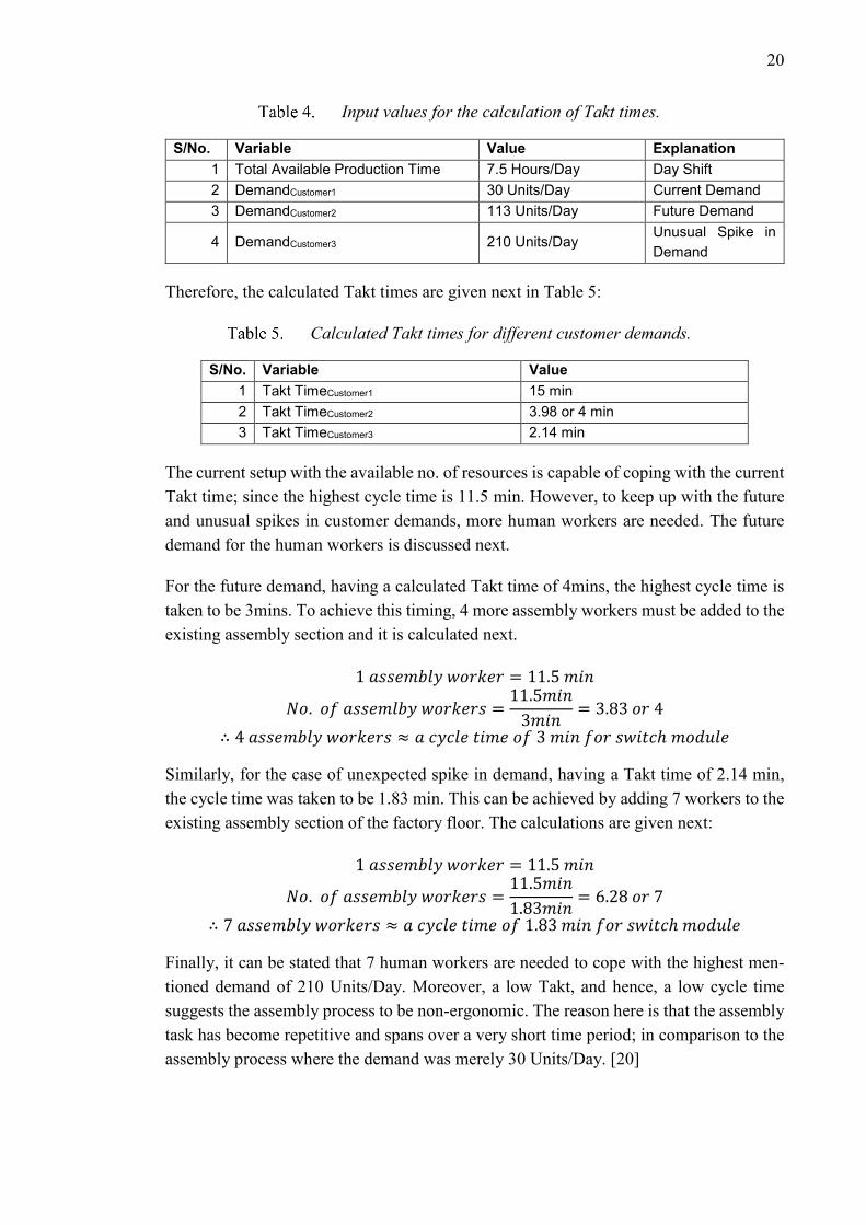
Input values for the calculation of Takt times.
S/No. Variable Value Explanation
1 Total Available Production Time 7.5 Hours/Day Day Shift
2 DemandCustomer1 30 Units/Day Current Demand
3 DemandCustomer2 113 Units/Day Future Demand
4 DemandCustomer3 210 Units/Day Unusual Spike in
Demand
Therefore, the calculated Takt times are given next in Table 5:
Calculated Takt times for different customer demands.
S/No. Variable Value
1 Takt TimeCustomer1 15 min
2 Takt TimeCustomer2 3.98 or 4 min
3 Takt TimeCustomer3 2.14 min
The current setup with the available no. of resources is capable of coping with the current
Takt time; since the highest cycle time is 11.5 min. However, to keep up with the future
and unusual spikes in customer demands, more human workers are needed. The future
demand for the human workers is discussed next.
For the future demand, having a calculated Takt time of 4mins, the highest cycle time is
taken to be 3mins. To achieve this timing, 4 more assembly workers must be added to the
existing assembly section and it is calculated next.
1 𝑎𝑠𝑠𝑒𝑚𝑏𝑙𝑦 𝑤𝑜𝑟𝑘𝑒𝑟 = 11.5 𝑚𝑖𝑛
𝑁𝑜. 𝑜𝑓 𝑎𝑠𝑠𝑒𝑚𝑙𝑏𝑦 𝑤𝑜𝑟𝑘𝑒𝑟𝑠 =11.5𝑚𝑖𝑛
3𝑚𝑖𝑛= 3.83 𝑜𝑟 4
∴ 4 𝑎𝑠𝑠𝑒𝑚𝑏𝑙𝑦 𝑤𝑜𝑟𝑘𝑒𝑟𝑠 ≈ 𝑎 𝑐𝑦𝑐𝑙𝑒 𝑡𝑖𝑚𝑒 𝑜𝑓 3 𝑚𝑖𝑛 𝑓𝑜𝑟 𝑠𝑤𝑖𝑡𝑐ℎ 𝑚𝑜𝑑𝑢𝑙𝑒
Similarly, for the case of unexpected spike in demand, having a Takt time of 2.14 min,
the cycle time was taken to be 1.83 min. This can be achieved by adding 7 workers to the
existing assembly section of the factory floor. The calculations are given next:
1 𝑎𝑠𝑠𝑒𝑚𝑏𝑙𝑦 𝑤𝑜𝑟𝑘𝑒𝑟 = 11.5 𝑚𝑖𝑛
𝑁𝑜. 𝑜𝑓 𝑎𝑠𝑠𝑒𝑚𝑏𝑙𝑦 𝑤𝑜𝑟𝑘𝑒𝑟𝑠 =11.5𝑚𝑖𝑛
1.83𝑚𝑖𝑛= 6.28 𝑜𝑟 7
∴ 7 𝑎𝑠𝑠𝑒𝑚𝑏𝑙𝑦 𝑤𝑜𝑟𝑘𝑒𝑟𝑠 ≈ 𝑎 𝑐𝑦𝑐𝑙𝑒 𝑡𝑖𝑚𝑒 𝑜𝑓 1.83 𝑚𝑖𝑛 𝑓𝑜𝑟 𝑠𝑤𝑖𝑡𝑐ℎ 𝑚𝑜𝑑𝑢𝑙𝑒
Finally, it can be stated that 7 human workers are needed to cope with the highest men-
tioned demand of 210 Units/Day. Moreover, a low Takt, and hence, a low cycle time
suggests the assembly process to be non-ergonomic. The reason here is that the assembly
task has become repetitive and spans over a very short time period; in comparison to the
assembly process where the demand was merely 30 Units/Day. [20]

21
3.4 Human Robot Collaborative Assembly Process
For the customer demand of 113 Units/Day, the Takt time was calculated to be 4 min.
And to achieve this, 4 more assembly workers need to be added to the assembly floor.
Alternatively, the same result can be achieved by the addition of 2 human workers along-
side 2 collaborative robots. Moreover, if there is an unusual spike in the customer demand
i.e. 210 Units/Day then it could be managed by doubling the resources required to meet
the demand of 113 Units/Day. This is calculated next:
113𝑈𝑛𝑖𝑡𝑠
𝐷𝑎𝑦× 2 = 226
𝑈𝑛𝑖𝑡𝑠
𝐷𝑎𝑦
Therefore, as per the initial analysis, the collaborative setup has the potential of reaching
226 Units/Day. However, the main idea here is to shift the non-ergonomic tasks from the
human worker to the COBOT. Additionally, the COBOT setup also offers flexibility in
terms of operational deployment. For instance, the COBOT, when needed, can easily be
shifted from the sheet cutting area of the factory to the assembly area of the factory; in
order to assist the human worker in meeting the customer demand. In case of a temporary
demand, it is considered rather convenient and quick to deploy a COBOT than to hire a
new assembly worker for a short period of time. [20]
Figure 12. Simulated human robot collaborative assembly process. [20]
Figure 12 shows the simulated scenario where the human worker performs the assembly
task in collaboration with the collaborative robot. The task distribution among the human
worker and the robot is given next in Table 6. During the execution of task no.1, the robot
picks the DIN rail from the feeder and places it on the assembly table. The human worker
secures the DIN rail with the help of a toggle clamp. After this, during the execution of
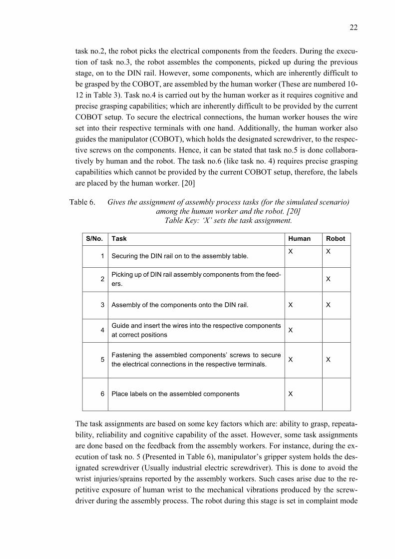
22
task no.2, the robot picks the electrical components from the feeders. During the execu-
tion of task no.3, the robot assembles the components, picked up during the previous
stage, on to the DIN rail. However, some components, which are inherently difficult to
be grasped by the COBOT, are assembled by the human worker (These are numbered 10-
12 in Table 3). Task no.4 is carried out by the human worker as it requires cognitive and
precise grasping capabilities; which are inherently difficult to be provided by the current
COBOT setup. To secure the electrical connections, the human worker houses the wire
set into their respective terminals with one hand. Additionally, the human worker also
guides the manipulator (COBOT), which holds the designated screwdriver, to the respec-
tive screws on the components. Hence, it can be stated that task no.5 is done collabora-
tively by human and the robot. The task no.6 (like task no. 4) requires precise grasping
capabilities which cannot be provided by the current COBOT setup, therefore, the labels
are placed by the human worker. [20]
Gives the assignment of assembly process tasks (for the simulated scenario)
among the human worker and the robot. [20]
Table Key: ‘X’ sets the task assignment.
S/No. Task Human Robot
1 Securing the DIN rail on to the assembly table. X
X
2 Picking up of DIN rail assembly components from the feed-
ers. X
3 Assembly of the components onto the DIN rail. X X
4 Guide and insert the wires into the respective components
at correct positions X
5 Fastening the assembled components’ screws to secure
the electrical connections in the respective terminals. X X
6 Place labels on the assembled components X
The task assignments are based on some key factors which are: ability to grasp, repeata-
bility, reliability and cognitive capability of the asset. However, some task assignments
are done based on the feedback from the assembly workers. For instance, during the ex-
ecution of task no. 5 (Presented in Table 6), manipulator’s gripper system holds the des-
ignated screwdriver (Usually industrial electric screwdriver). This is done to avoid the
wrist injuries/sprains reported by the assembly workers. Such cases arise due to the re-
petitive exposure of human wrist to the mechanical vibrations produced by the screw-
driver during the assembly process. The robot during this stage is set in complaint mode

23
(discussed in detail in the later chapters of the thesis). This helps the operator in guiding
and positioning of the screwdriver. The positioning is done in line with the specific screw
(to be fastened) of the respective electrical component. Moreover, once the fastening op-
eration starts, the unwanted vibrational energy generated by the screwdriver is effectively
dissipated via virtual damper implemented as part of the complaint behavior of the ma-
nipulator. [20]
Comparison of collaborative robot setups. [20]
S/No. Organization COBOT Reach Payload Autonomous
Mobile Unit Gripper
1 KONE Corp. KUKA LBR iiwa
14 R820 820mm 14kg
KUKA flex-
FELLOW
H750 ex-
tended
Robotiq’s
Adaptive 2
finger grip-
per
2 TTY Founda-
tion.
KUKA LBR iiwa
7 R800 800mm 7kg
KUKA flex-
FELLOW
H750 ex-
tended
SCHUNK
EGP 50
Gripper (2
finger grip-
per for
small parts)
Table 7 gives the comparison between the COBOT setups. KONE Corporation’s setup
has more reach and can take more load. This enables it to be deployed elsewhere in the
factory where it is needed. And it can effectively have more than one tool attached at the
end of the robotic arm. Since both the setups are similar, and to promote Industry-Aca-
demia collaboration, the simulated scenario along with the items given in Table 3 were
provided to the ‘Mechanical Engineering and Industrial Systems Laboratory’ of Tampere
University of Technology (also referred to as TTY Foundation.). It was done to explore
the simulated results in a practical environment. Additionally, it was encouraged to design
the assembly process with the idea of human worker having gone through the operator’s
training and having no skills in programming related knowledge areas. Therefore, the
upcoming chapters discuss the design and commissioning of collaborative setup along
with the productivity of the human robot collaborative assembly process.
24
4. SYSTEM DESIGN - COLLABORATIVE OPERA-
TION
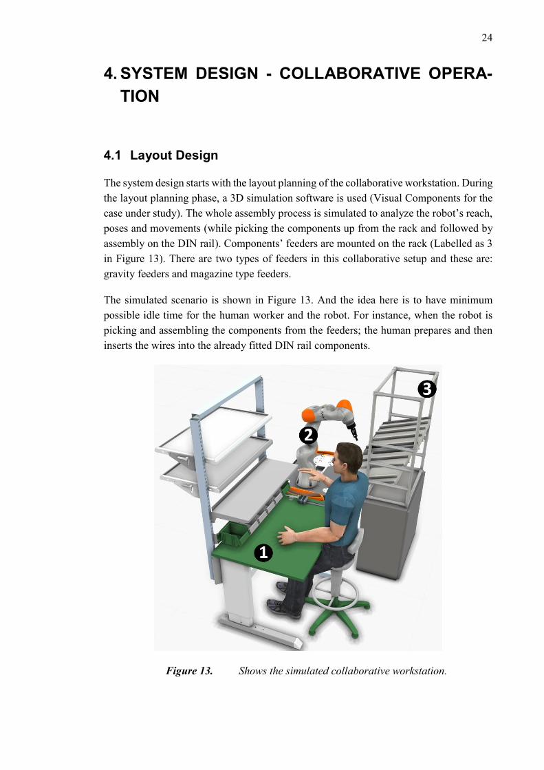
4.1 Layout Design
The system design starts with the layout planning of the collaborative workstation. During
the layout planning phase, a 3D simulation software is used (Visual Components for the
case under study). The whole assembly process is simulated to analyze the robot’s reach,
poses and movements (while picking the components up from the rack and followed by
assembly on the DIN rail). Components’ feeders are mounted on the rack (Labelled as 3
in Figure 13). There are two types of feeders in this collaborative setup and these are:
gravity feeders and magazine type feeders.
The simulated scenario is shown in Figure 13. And the idea here is to have minimum
possible idle time for the human worker and the robot. For instance, when the robot is
picking and assembling the components from the feeders; the human prepares and then
inserts the wires into the already fitted DIN rail components.
Figure 13. Shows the simulated collaborative workstation.
25
Figure 13 shows the collaborative workstation and this setup can be functionally divided
into 3 parts. These are given next (as labelled in Figure 13 respectively):
1. Assembly table fitted with a toggle clamp to secure the DIN rail in a fixed posi-
tion.
2. The COBOT setup – ‘KUKA LBR IIWA 7 R800’ mounted on ‘KUKA flexFEL-
LOW H750 extended’.
3. Component inventory rack with feeders.
Figure 14. The top view of the collaborative workstation layout. Area enclosed
in red boundary indicates the overlap region of human worker and COBOT’s
workspace (also known as collaborative workspace).
Area enclosed in green marks the human worker’s workspace.
Area enclosed by blue is robot’s workspace.
NOTE: All the dimensions are in millimeters.
Figure 14 is used to identify robot’s operational space and collaborative workspace. Col-
laborative workspace, as defined in [11], is the shared region between the human worker
and the robot. During the assembly process, the human and the COBOT work simultane-
ously in cooperation within this workspace. To detect the presence of human in the col-
laborative workspace, COBOT’s inherent position and joint torque sensors were consid-
ered in this design. No external sensors (e.g. laser scanners, cameras etc.) were considered
while designing the layout plan.
26
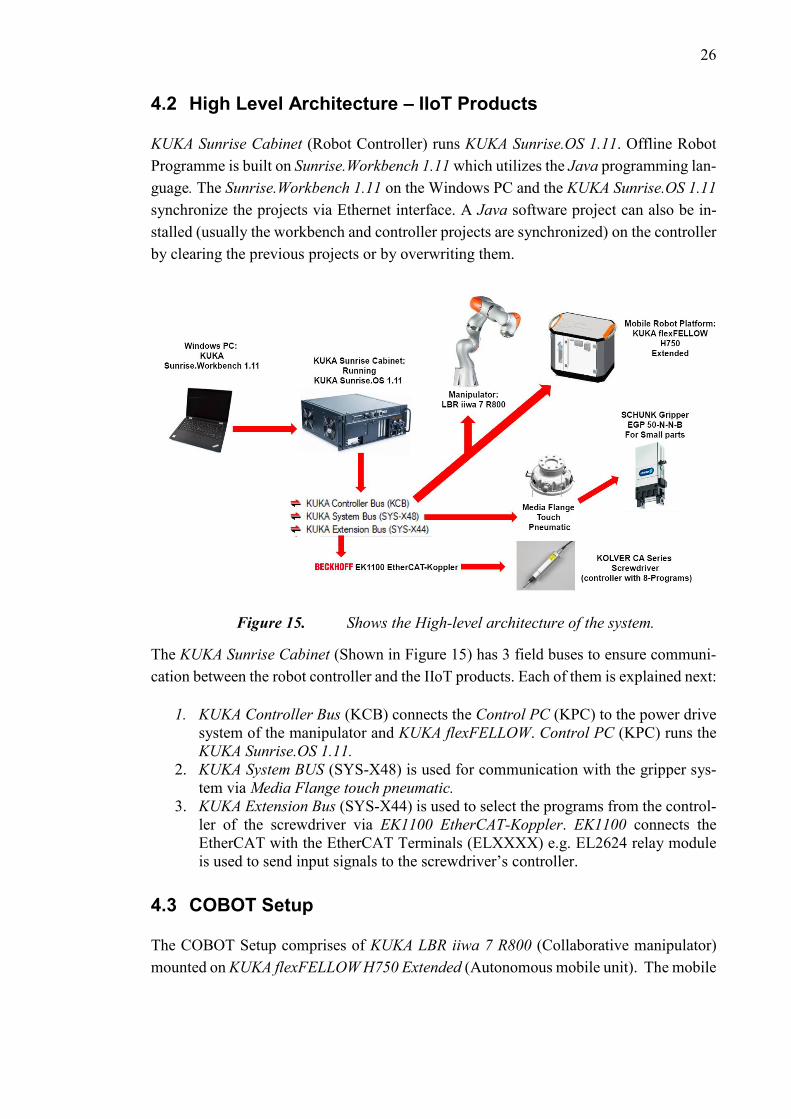
4.2 High Level Architecture – IIoT Products
KUKA Sunrise Cabinet (Robot Controller) runs KUKA Sunrise.OS 1.11. Offline Robot
Programme is built on Sunrise.Workbench 1.11 which utilizes the Java programming lan-
guage. The Sunrise.Workbench 1.11 on the Windows PC and the KUKA Sunrise.OS 1.11
synchronize the projects via Ethernet interface. A Java software project can also be in-
stalled (usually the workbench and controller projects are synchronized) on the controller
by clearing the previous projects or by overwriting them.
Figure 15. Shows the High-level architecture of the system.
The KUKA Sunrise Cabinet (Shown in Figure 15) has 3 field buses to ensure communi-
cation between the robot controller and the IIoT products. Each of them is explained next:
1. KUKA Controller Bus (KCB) connects the Control PC (KPC) to the power drive
system of the manipulator and KUKA flexFELLOW. Control PC (KPC) runs the
KUKA Sunrise.OS 1.11.
2. KUKA System BUS (SYS-X48) is used for communication with the gripper sys-
tem via Media Flange touch pneumatic.
3. KUKA Extension Bus (SYS-X44) is used to select the programs from the control-
ler of the screwdriver via EK1100 EtherCAT-Koppler. EK1100 connects the
EtherCAT with the EtherCAT Terminals (ELXXXX) e.g. EL2624 relay module
is used to send input signals to the screwdriver’s controller.
4.3 COBOT Setup
The COBOT Setup comprises of KUKA LBR iiwa 7 R800 (Collaborative manipulator)
mounted on KUKA flexFELLOW H750 Extended (Autonomous mobile unit). The mobile
27
unit acts as a base for the manipulator and houses the control/accessory units of the at-
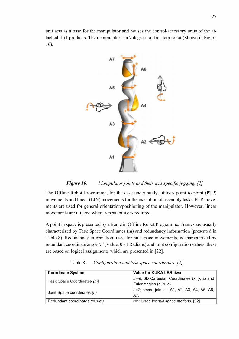
tached IIoT products. The manipulator is a 7 degrees of freedom robot (Shown in Figure
16).
Figure 16. Manipulator joints and their axis specific jogging. [2]
The Offline Robot Programme, for the case under study, utilizes point to point (PTP)
movements and linear (LIN) movements for the execution of assembly tasks. PTP move-
ments are used for general orientation/positioning of the manipulator. However, linear
movements are utilized where repeatability is required.
A point in space is presented by a frame in Offline Robot Programme. Frames are usually
characterized by Task Space Coordinates (m) and redundancy information (presented in
Table 8). Redundancy information, used for null space movements, is characterized by
redundant coordinate angle ‘r’ (Value: 0 - 1 Radians) and joint configuration values; these
are based on logical assignments which are presented in [22].
Configuration and task space coordinates. [2]
Coordinate System Value for KUKA LBR iiwa
Task Space Coordinates (m) m=6; 3D Cartesian Coordinates (x, y, z) and
Euler Angles (a, b, c)
Joint Space coordinates (n) n=7; seven joints – A1, A2, A3, A4, A5, A6,
A7.
Redundant coordinates (r=n-m) r=1; Used for null space motions. [22]
28
During the execution of null space movements, the end effector’s position and orientation
is constant in space (m is constant in space). The idea behind null space movements is
based on the fact that a point in the Cartesian space can be reached with multiple joint
configurations (different set of joint values). Thus, the redundancy information is used to
avoid unambiguous joint configurations during the planning and execution of different
robot motions. During null space movements, the value of ‘r’ depends on the freedom of
the 3rd joint. [22]
4.3.1 Sensors and available control modes
The KUKA iiwa LBR series manipulators, inherently, have two types of joint sensors and
these are:
1. Joint position sensors
2. Joint torque sensors
In an ordinary industrial robot, joint position sensors are, generally, available only. How-
ever, the controller implementations, are made possible due to the mentioned joint sen-
sors. There are two types of controller implementations and these are:
1. Position controller
2. Cartesian impedance controller
Position controller makes sure that the current position always matches the set point on
the commanded trajectory with minimal possible difference. Position controllers treat the
external stimuli as disturbances and make sure that the set point is reached with minimum
possible difference. Therefore, if there is any obstruction in the planned path then the
robot tries to counter it by reacting towards it as a rigid structure. Apart from the damage
to the robot’s surrounding, excessive buildup of forces around or on the manipulator could
ultimately damage it. Class PositionControlMode represents the position controller in
Java Robot Offline Programme. If no control mode is specified in the Robot Offline Pro-
gramme then this controller is utilized by default.

29
Figure 17. Generic model of an impedance controller. Adapted from [23]
Cartesian impedance controller enables active compliance (complaint model discussed
next in detail) for the robot. It is realized by acting on the information delivered by inher-
ent sensors of the robot. The robot becomes sensitive to external stimuli like obstacles
and forces. The whole kinematic chain becomes less rigid and more sensitive. External
forces in the robot’s path can cause it to deviate from its planned path. Cartesian imped-
ance controller can be utilized through the class CartesianImpedanceControlMode in Ro-
bot Offline Programme. Figure 17 gives the concept of impedance controller. Whereas,
the description of variables used in Figure 17 are given next:
𝒙𝒅 ∶ 𝑃𝑜𝑖𝑛𝑡 𝑎𝑙𝑜𝑛𝑔 𝑡ℎ𝑒 𝑐𝑜𝑚𝑚𝑎𝑛𝑑𝑒𝑑 𝑡𝑟𝑎𝑗𝑒𝑐𝑡𝑜𝑟𝑦 𝑖𝑛 𝑠𝑝𝑎𝑐𝑒. 𝒙 ∶ 𝐶𝑢𝑟𝑟𝑒𝑛𝑡 𝑝𝑜𝑠𝑖𝑡𝑖𝑜𝑛 (𝑇𝐶𝑃 𝑓𝑜𝑟 𝑜𝑢𝑟 𝑐𝑎𝑠𝑒) 𝝉𝒎𝒐𝒕𝒐𝒓 ∶ 𝑀𝑜𝑡𝑜𝑟 𝑡𝑜𝑟𝑞𝑢𝑒 𝑎𝑠 𝑜𝑢𝑡𝑝𝑢𝑡
According to [24], a compliant mechanism is defined as, “Mechanical systems which use
their structural elastic deflection as a function.” In manipulators, active compliance is
achieved by introducing a virtual spring-mass-damper system (Shown in Figure 18) in-
between the end effector (TCP) of the manipulator and the commanded trajectory. The
equation for the second order damped harmonic oscillator (spring-mass-damper system),
as mentioned in [23], is given next:
𝑴𝒔 ∙ (𝒙�̈� − �̈�) + 𝑩𝒔 ∙ (𝒙�̇� − �̇�) + 𝑲𝒔 ∙ (𝒙𝒅 − 𝒙) = 𝑭𝒆𝒙𝒕𝒆𝒓𝒏𝒂𝒍 → (3)
Where,
𝑴𝒔 ∶ 𝑀𝑎𝑠𝑠 𝑚𝑎𝑡𝑟𝑖𝑥 𝑜𝑓 𝑡ℎ𝑒 𝑠𝑦𝑠𝑡𝑒𝑚. 𝑩𝒔 ∶ 𝐷𝑎𝑚𝑝𝑖𝑛𝑔 𝑀𝑎𝑡𝑟𝑖𝑥 𝑜𝑓 𝑡ℎ𝑒 𝑠𝑦𝑠𝑡𝑒𝑚. 𝑲𝒔 ∶ 𝑆𝑡𝑖𝑓𝑓𝑛𝑒𝑠𝑠 𝑀𝑎𝑡𝑟𝑖𝑥 𝑜𝑓 𝑡ℎ𝑒 𝑠𝑦𝑠𝑡𝑒𝑚. 𝑭𝒆𝒙𝒕𝒆𝒓𝒏𝒂𝒍 ∶ 𝑁𝑒𝑡 𝑒𝑥𝑡𝑒𝑟𝑛𝑎𝑙 𝑓𝑜𝑟𝑐𝑒 𝑚𝑎𝑡𝑟𝑖𝑥
The values of 𝑲𝒔 and 𝑩𝒔 can be assigned in the Robot Offline Programme. Whereas, the
mass matrix is determined, inherently, by the KUKA Sunrise.OS 1.11’s robotic applica-
tions package - ‘com.kuka.roboticsAPI’. It is based on end effector’s load information
and manipulator’s inertial parameters.
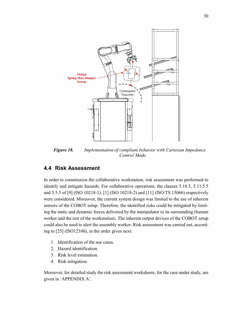
30
Figure 18. Implementation of compliant behavior with Cartesian Impedance
Control Mode.
4.4 Risk Assessment
In order to commission the collaborative workstation, risk assessment was performed to
identify and mitigate hazards. For collaborative operations, the clauses 5.10.5, 5.11.5.5
and 5.5.5 of [9] (ISO 10218-1), [1] (ISO 10218-2) and [11] (ISO/TS 15066) respectively
were considered. Moreover, the current system design was limited to the use of inherent
sensors of the COBOT setup. Therefore, the identified risks could be mitigated by limit-
ing the static and dynamic forces delivered by the manipulator to its surrounding (human
worker and the rest of the workstation). The inherent output devices of the COBOT setup
could also be used to alert the assembly worker. Risk assessment was carried out, accord-
ing to [25] (ISO12100), in the order given next:
1. Identification of the use cases.
2. Hazard identification.
3. Risk level estimation.
4. Risk mitigation.
Moreover, for detailed study the risk assessment worksheets, for the case under study, are
given in ‘APPENDIX A’.

31
4.4.1 Identification of the use cases
The first step involves identification of the use cases, their respective actors and fre-
quency. A total of 7 use cases were identified and these are given next:
1. Commissioning and robot offline programming
2. Assembly Operation – Automatic mode
3. Human Intervention in Robot only operating zone
4. Foreseeable malpractices in the assembly process
5. Maintenance/Service of collaborative workstation
6. Cleaning/Housekeeping
7. Decommissioning
The first use case involves commissioning of the robot and its offline programming. It is
carried out by a certified robot commissioning engineer. This is done during the planning
phase of the assembly process and the activity is carried out quite rarely; unless, a major
change in the assembly process has to carried out. For instance, mapping of additional
IIoT products (additional sensors or grippers) in the Robot Offline Programme.
The second use case involves the assembly operation. The robot’s operation mode is set
to Automatic mode (AUT) in this case. As this is a value adding activity, therefore, it is
frequent and time consuming as compared to the other mentioned cases. Moreover, the
human assembly worker and the robot have a constant and frequent interaction as well;
since, they share the collaborative workspace (Area marked by red outline in Figure 14)
during this phase.
The third use case involves human intervention in the robot only workspace (Area marked
by blue outline in Figure 14). This case includes the human assembly worker; who has,
typically, gone through the operator’s training. However, the risky situation arises, if a
feeding problem is detected. And the detected problem needs immediate correction in
order to resume the normal assembly operation.
The fourth use case involves assembly process malpractices. This particular case focuses
on the presence of a non-authorized personal within the premises of collaborative work-
station. It could be anyone e.g. a visitor to the assembly area or a co-worker. The fre-
quency of occurrence for this event is unknown prior to the commissioning of the collab-
orative workstation. Since, the risk assessment is done, beforehand, during the planning
stage.
The fifth use case involves the maintenance/service of the collaborative workstation. It is
usually carried out by a trained technician/engineer. Maintenance/service activities are
considered rare as these are usually carried out once a year.
32
The sixth use case involves housekeeping of the Collaborative workstation. It is carried
out, on a daily basis by the human assembly worker, at the end of the work shift.
The last use case is about decommissioning of the collaborative workstation. It is carried
out to ship the workstation. Or it could be done in order to dispose the workstation. It is
considered to be a rare event as compared to the other mentioned use case activities.
4.4.2 Hazard identification
The second stage involves identification of hazards related to the previously mentioned
use cases. 4 types of hazards were identified for the use cases and these are given next:
1. Entering Robot’s Workspace
2. Transient Contact
3. Quasi-Static Contact
4. Damage to the workstation (All 3 functional zones)
4.4.3 Risk level estimation
For the evaluation of risks involved in the already mentioned use cases, hazard rating
number system was utilized. Table 9 gives the estimated risk levels.
It is observed that use case no. 2 and 4 have a higher risk level as compared to the rest of
the use cases. During collaborative assembly the human assembly worker and the robot
share the workspace all the time. They interact constantly during the whole assembly
process. Therefore, the risk is considerable.
Moreover, for use case no.4, the risk is also considerable. The reason for this is based on
the assumption that the non-authorized person (or persons) entering the collaborative
workstation has not received any training or orientation for the collaborative work cell.
Therefore, such an act could expose the work cell and its surrounding to unforeseeable
hazards.
Risk level estimation results
S/No. Use Case Risk Level
1 Commissioning and robot offline programming Very Low Risk
2 Assembly Operation – Automatic mode Considerable Risk
3 Human Intervention in Robot only operating zone Very Low Risk
4 Foreseeable malpractices in assembly process Considerable Risk
5 Maintenance/Service of collaborative workstation Meaningless risk
6 Cleaning/Housekeeping Meaningless risk
7 Decommissioning Meaningless risk
33
For the use cases no. 1 and 3 the risk is determined to be very low. The reason for it is
based on the assumption that the use case actors i.e. commissioning engineer and the
assembly worker will have gone through necessary work cell trainings and orientation
sessions.
For the use case no.1 the frequency of occurrence is low. However, in case of a collision
between the manipulator and its surroundings, the damage could be considerable. The
reason for this is that the safety features of the robot might not be well established during
the different stages of robot commissioning process.
For the use case no. 3, the human assembly worker enters the robot workspace if there is
an issue with the feeders. And it is assumed to be rare. However, in case of a contact with
the robot, the injury is assumed to be minor at maximum.
For the use cases no. 5 to 7, the risk is estimated to be meaningless. The reason behind it
is that the robot during these cases is assumed to not be in the automatic operation mode.
For maintenance tasks, it is assumed to be operating in KRF mode (recovery mode). This
is the case when the robot has encountered an unwanted situation and needs to be retracted
for service/maintenance. For the case of house keeping it is assumed that no robot appli-
cation is running, and the joint brakes are active. Similarly, for decommissioning the robot
it is assumed to be set in Transport position while utilizing T1 or T2 operating mode
(operation modes with controlled speeds). Dead man’s switch is available during these
operating modes.
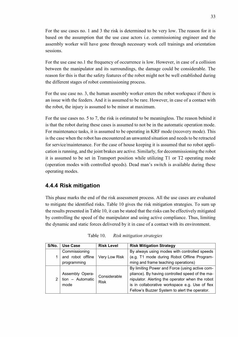
4.4.4 Risk mitigation
This phase marks the end of the risk assessment process. All the use cases are evaluated
to mitigate the identified risks. Table 10 gives the risk mitigation strategies. To sum up
the results presented in Table 10, it can be stated that the risks can be effectively mitigated
by controlling the speed of the manipulator and using active compliance. Thus, limiting
the dynamic and static forces delivered by it in case of a contact with its environment.
Risk mitigation strategies
S/No. Use Case Risk Level Risk Mitigation Strategy
1
Commissioning
and robot offline
programming
Very Low Risk
By always using modes with controlled speeds
(e.g. T1 mode during Robot Offline Program-
ming and frame teaching operations)
2
Assembly Opera-
tion – Automatic
mode
Considerable
Risk
By limiting Power and Force (using active com-
pliance). By having controlled speed of the ma-
nipulator. Alerting the operator when the robot
is in collaborative workspace e.g. Use of flex
Fellow’s Buzzer System to alert the operator.
34
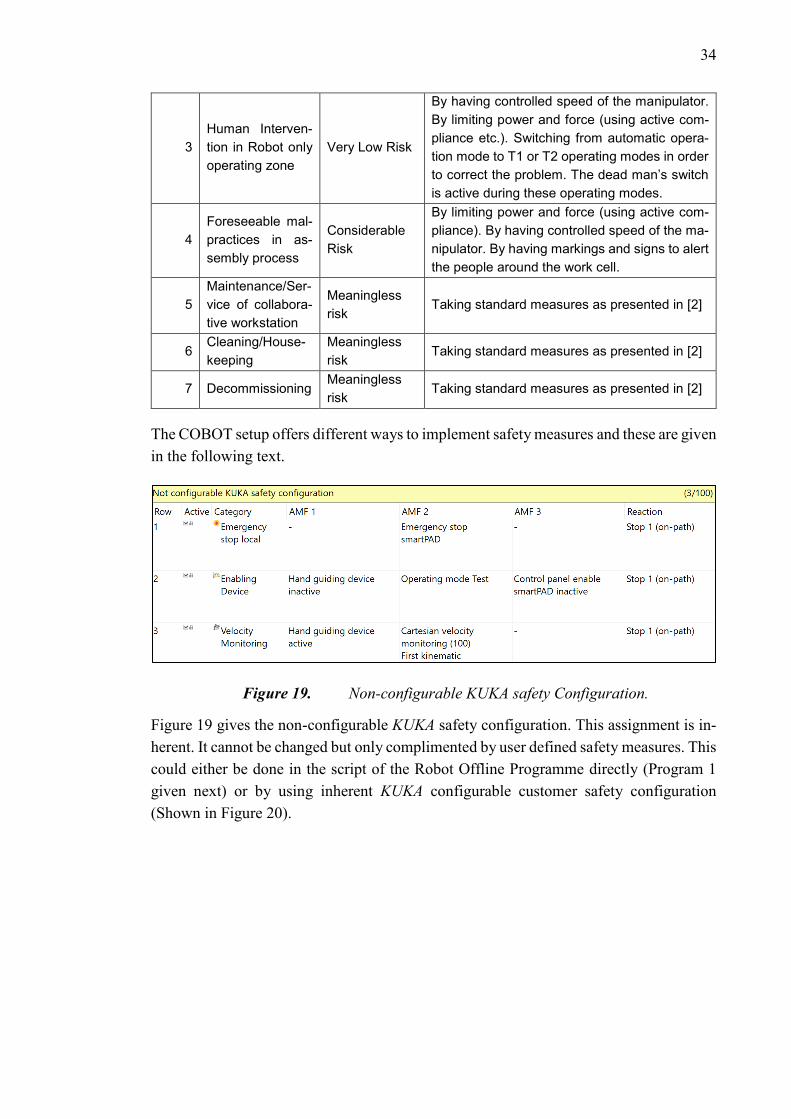
3
Human Interven-
tion in Robot only
operating zone
Very Low Risk
By having controlled speed of the manipulator.
By limiting power and force (using active com-
pliance etc.). Switching from automatic opera-
tion mode to T1 or T2 operating modes in order
to correct the problem. The dead man’s switch
is active during these operating modes.
4
Foreseeable mal-
practices in as-
sembly process
Considerable
Risk
By limiting power and force (using active com-
pliance). By having controlled speed of the ma-
nipulator. By having markings and signs to alert
the people around the work cell.
5
Maintenance/Ser-
vice of collabora-
tive workstation
Meaningless
risk Taking standard measures as presented in [2]
6 Cleaning/House-
keeping
Meaningless
risk Taking standard measures as presented in [2]
7 Decommissioning Meaningless
risk Taking standard measures as presented in [2]
The COBOT setup offers different ways to implement safety measures and these are given
in the following text.
Figure 19. Non-configurable KUKA safety Configuration.
Figure 19 gives the non-configurable KUKA safety configuration. This assignment is in-
herent. It cannot be changed but only complimented by user defined safety measures. This
could either be done in the script of the Robot Offline Programme directly (Program 1
given next) or by using inherent KUKA configurable customer safety configuration
(Shown in Figure 20).
35
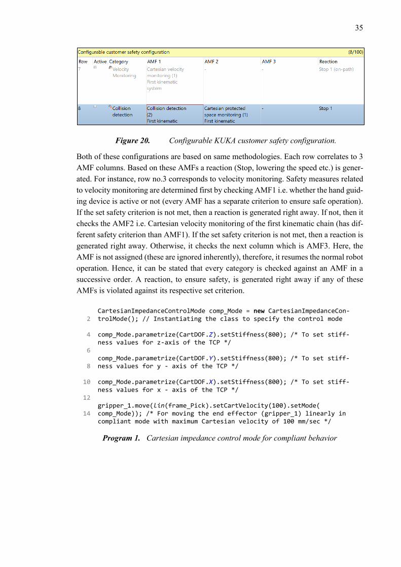
Figure 20. Configurable KUKA customer safety configuration.
Both of these configurations are based on same methodologies. Each row correlates to 3
AMF columns. Based on these AMFs a reaction (Stop, lowering the speed etc.) is gener-
ated. For instance, row no.3 corresponds to velocity monitoring. Safety measures related
to velocity monitoring are determined first by checking AMF1 i.e. whether the hand guid-
ing device is active or not (every AMF has a separate criterion to ensure safe operation).
If the set safety criterion is not met, then a reaction is generated right away. If not, then it
checks the AMF2 i.e. Cartesian velocity monitoring of the first kinematic chain (has dif-
ferent safety criterion than AMF1). If the set safety criterion is not met, then a reaction is
generated right away. Otherwise, it checks the next column which is AMF3. Here, the
AMF is not assigned (these are ignored inherently), therefore, it resumes the normal robot
operation. Hence, it can be stated that every category is checked against an AMF in a
successive order. A reaction, to ensure safety, is generated right away if any of these
AMFs is violated against its respective set criterion.
2
4
6
8
10
12
14
CartesianImpedanceControlMode comp_Mode = new CartesianImpedanceCon-trolMode(); // Instantiating the class to specify the control mode comp_Mode.parametrize(CartDOF.Z).setStiffness(800); /* To set stiff-ness values for z-axis of the TCP */ comp_Mode.parametrize(CartDOF.Y).setStiffness(800); /* To set stiff-ness values for y - axis of the TCP */ comp_Mode.parametrize(CartDOF.X).setStiffness(800); /* To set stiff-ness values for x - axis of the TCP */ gripper_1.move(lin(frame_Pick).setCartVelocity(100).setMode( comp_Mode)); /* For moving the end effector (gripper_1) linearly in compliant mode with maximum Cartesian velocity of 100 mm/sec */
Program 1. Cartesian impedance control mode for compliant behavior
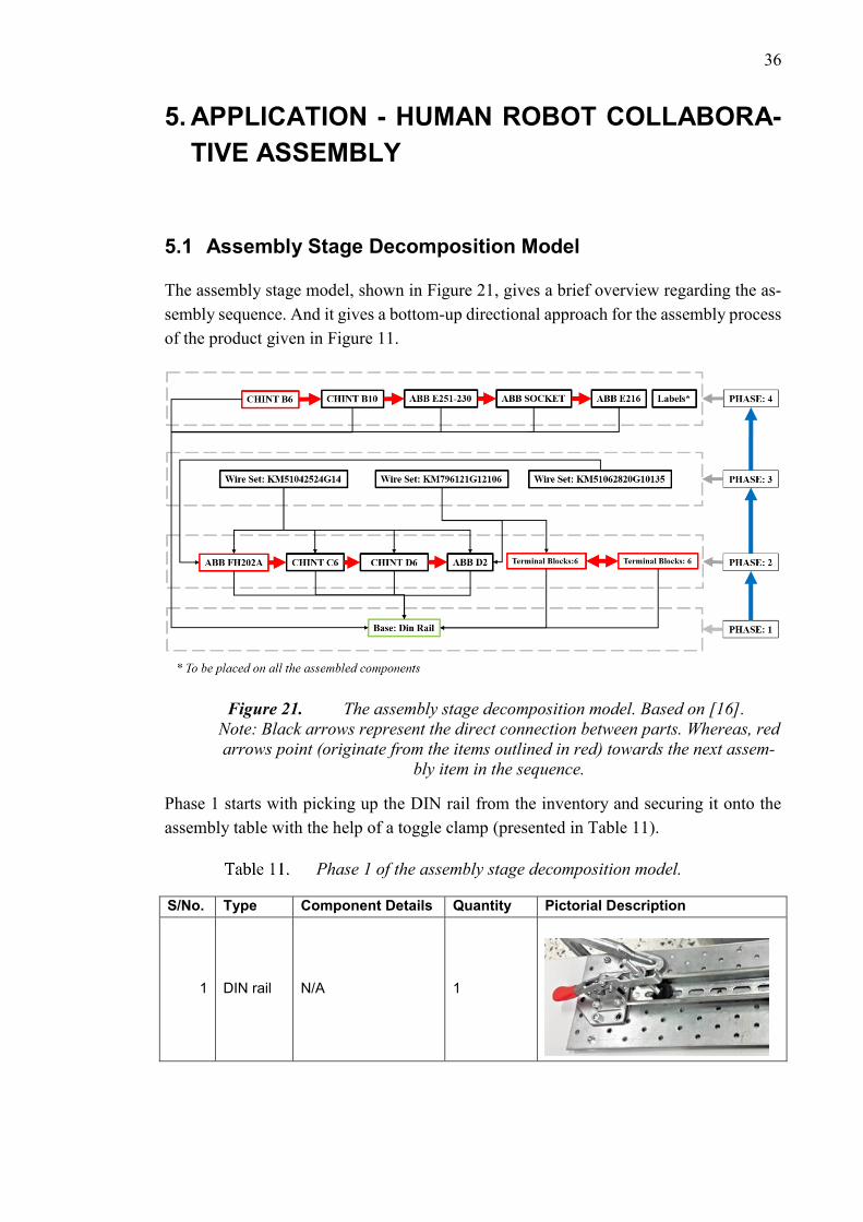
36
5. APPLICATION - HUMAN ROBOT COLLABORA-
TIVE ASSEMBLY
5.1 Assembly Stage Decomposition Model
The assembly stage model, shown in Figure 21, gives a brief overview regarding the as-
sembly sequence. And it gives a bottom-up directional approach for the assembly process
of the product given in Figure 11.
Figure 21. The assembly stage decomposition model. Based on [16].
Note: Black arrows represent the direct connection between parts. Whereas, red
arrows point (originate from the items outlined in red) towards the next assem-
bly item in the sequence.
Phase 1 starts with picking up the DIN rail from the inventory and securing it onto the
assembly table with the help of a toggle clamp (presented in Table 11).
Phase 1 of the assembly stage decomposition model.
S/No. Type Component Details Quantity Pictorial Description
1 DIN rail N/A 1
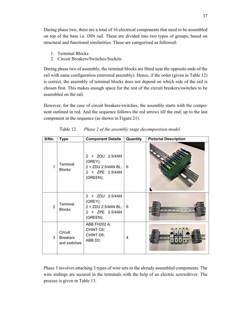
37
During phase two, there are a total of 16 electrical components that need to be assembled
on top of the base i.e. DIN rail. These are divided into two types of groups; based on
structural and functional similarities. These are categorized as followed:
1. Terminal Blocks
2. Circuit Breakers/Switches/Sockets
During phase two of assembly, the terminal blocks are fitted near the opposite ends of the
rail with same configuration (mirrored assembly). Hence, if the order (given in Table 12)
is correct, the assembly of terminal blocks does not depend on which side of the rail is
chosen first. This makes enough space for the rest of the circuit breakers/switches to be
assembled on the rail.
However, for the case of circuit breakers/switches, the assembly starts with the compo-
nent outlined in red. And the sequence follows the red arrows till the end; up to the last
component in the sequence (as shown in Figure 21).
Phase 2 of the assembly stage decomposition model.
S/No. Type Component Details Quantity Pictorial Description
1 Terminal
Blocks
2 × ZDU 2.5/4AN
(GREY);
2 × ZDU 2.5/4AN BL;
2 × ZPE 2.5/4AN
(GREEN);
6
2 Terminal
Blocks
2 × ZDU 2.5/4AN
(GREY);
2 × ZDU 2.5/4AN BL;
2 × ZPE 2.5/4AN
(GREEN);
6
3
Circuit
Breakers
and switches
ABB FH202 A;
CHINT C6;
CHINT D6;
ABB D2;
4
Phase 3 involves attaching 3 types of wire sets to the already assembled components. The
wire endings are secured in the terminals with the help of an electric screwdriver. The
process is given in Table 13.
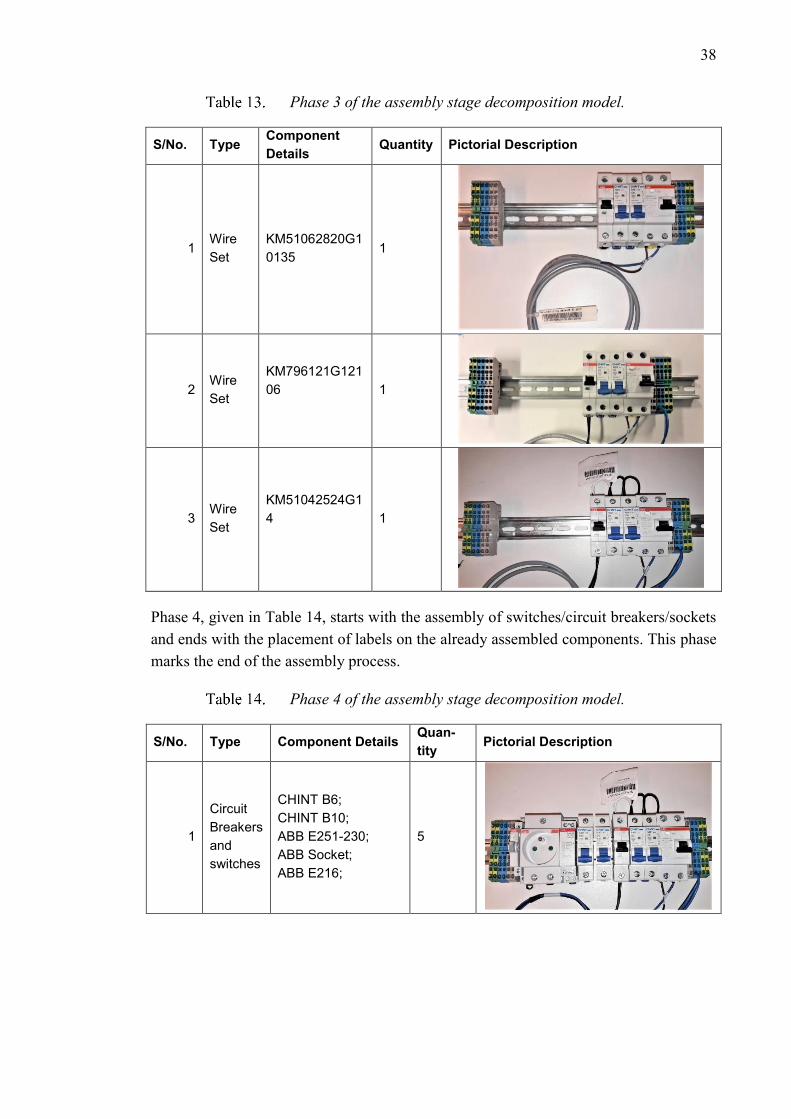
38
Phase 3 of the assembly stage decomposition model.
S/No. Type Component
Details Quantity Pictorial Description
1 Wire
Set
KM51062820G1
0135 1
2 Wire
Set
KM796121G121
06
1
3 Wire
Set
KM51042524G1
4
1
Phase 4, given in Table 14, starts with the assembly of switches/circuit breakers/sockets
and ends with the placement of labels on the already assembled components. This phase
marks the end of the assembly process.
Phase 4 of the assembly stage decomposition model.
S/No. Type Component Details Quan-
tity Pictorial Description
1
Circuit
Breakers
and
switches
CHINT B6;
CHINT B10;
ABB E251-230;
ABB Socket;
ABB E216;
5
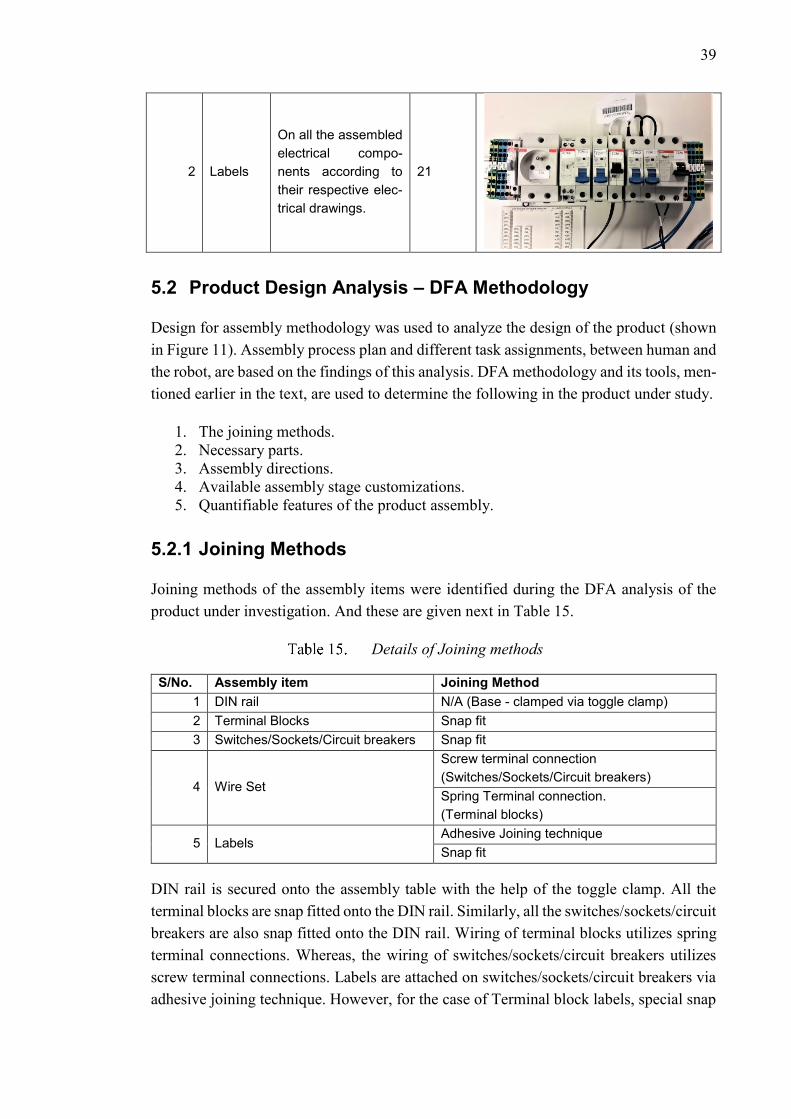
39
2 Labels
On all the assembled
electrical compo-
nents according to
their respective elec-
trical drawings.
21
5.2 Product Design Analysis – DFA Methodology
Design for assembly methodology was used to analyze the design of the product (shown
in Figure 11). Assembly process plan and different task assignments, between human and
the robot, are based on the findings of this analysis. DFA methodology and its tools, men-
tioned earlier in the text, are used to determine the following in the product under study.
1. The joining methods.
2. Necessary parts.
3. Assembly directions.
4. Available assembly stage customizations.
5. Quantifiable features of the product assembly.
5.2.1 Joining Methods
Joining methods of the assembly items were identified during the DFA analysis of the
product under investigation. And these are given next in Table 15.
Details of Joining methods
S/No. Assembly item Joining Method
1 DIN rail N/A (Base - clamped via toggle clamp)
2 Terminal Blocks Snap fit
3 Switches/Sockets/Circuit breakers Snap fit
4 Wire Set
Screw terminal connection
(Switches/Sockets/Circuit breakers)
Spring Terminal connection.
(Terminal blocks)
5 Labels Adhesive Joining technique
Snap fit
DIN rail is secured onto the assembly table with the help of the toggle clamp. All the
terminal blocks are snap fitted onto the DIN rail. Similarly, all the switches/sockets/circuit
breakers are also snap fitted onto the DIN rail. Wiring of terminal blocks utilizes spring
terminal connections. Whereas, the wiring of switches/sockets/circuit breakers utilizes
screw terminal connections. Labels are attached on switches/sockets/circuit breakers via
adhesive joining technique. However, for the case of Terminal block labels, special snap
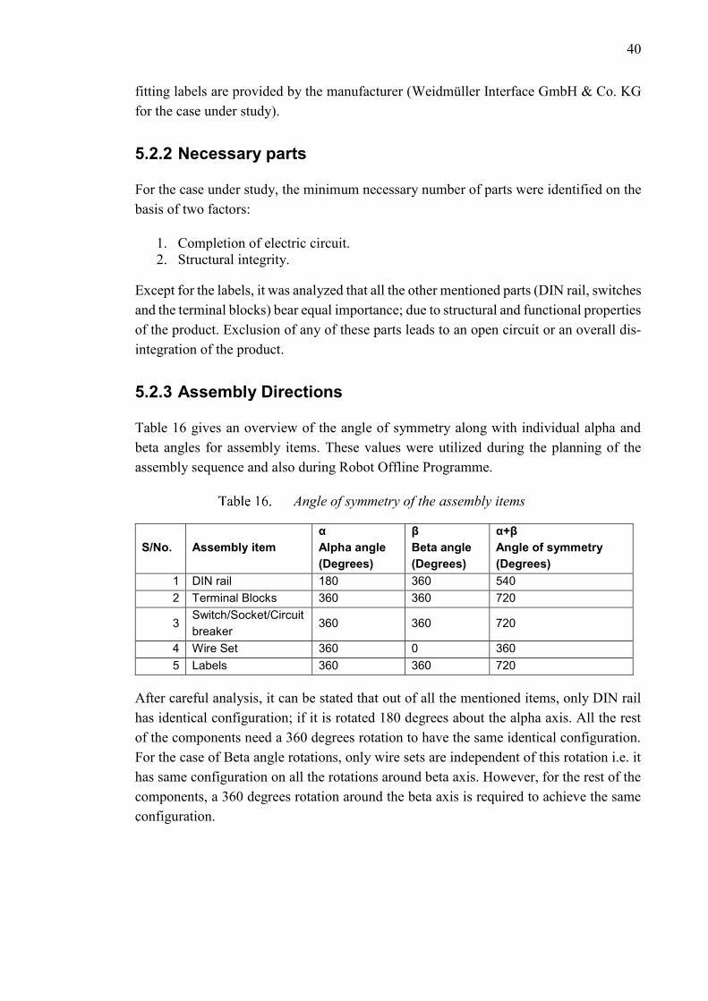
40
fitting labels are provided by the manufacturer (Weidmüller Interface GmbH & Co. KG
for the case under study).
5.2.2 Necessary parts
For the case under study, the minimum necessary number of parts were identified on the
basis of two factors:
1. Completion of electric circuit.
2. Structural integrity.
Except for the labels, it was analyzed that all the other mentioned parts (DIN rail, switches
and the terminal blocks) bear equal importance; due to structural and functional properties
of the product. Exclusion of any of these parts leads to an open circuit or an overall dis-
integration of the product.
5.2.3 Assembly Directions
Table 16 gives an overview of the angle of symmetry along with individual alpha and
beta angles for assembly items. These values were utilized during the planning of the
assembly sequence and also during Robot Offline Programme.
Angle of symmetry of the assembly items
S/No. Assembly item
α
Alpha angle
(Degrees)
β
Beta angle
(Degrees)
α+β
Angle of symmetry
(Degrees)
1 DIN rail 180 360 540
2 Terminal Blocks 360 360 720
3 Switch/Socket/Circuit
breaker 360 360 720
4 Wire Set 360 0 360
5 Labels 360 360 720
After careful analysis, it can be stated that out of all the mentioned items, only DIN rail
has identical configuration; if it is rotated 180 degrees about the alpha axis. All the rest
of the components need a 360 degrees rotation to have the same identical configuration.
For the case of Beta angle rotations, only wire sets are independent of this rotation i.e. it
has same configuration on all the rotations around beta axis. However, for the rest of the
components, a 360 degrees rotation around the beta axis is required to achieve the same
configuration.
41
5.2.4 Available assembly stage customizations
From Figure 21, it is examined that the following stages offer room for customizations
with regards to division of tasks among the robot and the human assembly worker:
1. Phase 2
2. Phase 3
3. Phase 4
This is also evident from Table 11-14. During phase 2, for instance, the terminal blocks
and the switches can be placed by the human worker and the robot simultaneously. During
phase 3, the human worker could, similarly, house the wires into the terminals. While the
robot holds the screwdriver in compliant mode for securing the wires. During the last
stage, the robot could assemble the rest of the DIN rail components from the shelf; while
the human prepares and puts the labels on all the already assembled components.
In case, there is any clearance between the assembled components then it can be removed
by pushing them to either side of the DIN rail. It can be done by the robot in compliant
mode. Otherwise, it can always be done by the human assembly worker. The same applies
if the parts are not assembled well.
5.2.5 Quantifiable features of the product assembly
In order to mitigate the previously mentioned risks and to increase the human assembly
worker’s awareness, two-digit manual assembly codes were generated on the basis of
conditional logic. Logical conditions were identified by analyzing assembly stage cus-
tomization options and assembly stage decomposition diagram.
Conditional assignment of the first digit of the manual assembly code.
S/No. Condition First Digit
1 The direction of approach is opposite to the Robot. 1
2 The direction of approach is opposite to the human assembly worker. 0
Table 17 and 18 give the key for the determination of manual assembly codes. For in-
stance, in case of a wire set, where the direction of approach towards the DIN rail is
opposite to the robot; the manual assembly code would be ‘01’.
Conditional assignment of the second digit of the manual assembly code.
S/No. Condition Second
Digit
1 Electrical Component / DIN rail / Label 1
2 Wire Set 0
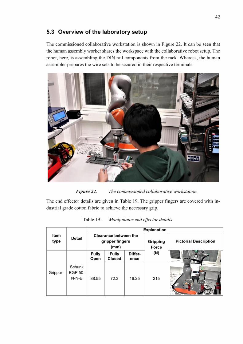
42
5.3 Overview of the laboratory setup
The commissioned collaborative workstation is shown in Figure 22. It can be seen that
the human assembly worker shares the workspace with the collaborative robot setup. The
robot, here, is assembling the DIN rail components from the rack. Whereas, the human
assembler prepares the wire sets to be secured in their respective terminals.
Figure 22. The commissioned collaborative workstation.
The end effector details are given in Table 19. The gripper fingers are covered with in-
dustrial grade cotton fabric to achieve the necessary grip.
Manipulator end effector details
Item
type Detail
Explanation
Clearance between the
gripper fingers
(mm)
Gripping
Force
(N)
Pictorial Description
Gripper
Schunk
EGP 50-
N-N-B
Fully Open
Fully Closed
Differ-ence
88.55 72.3 16.25 215
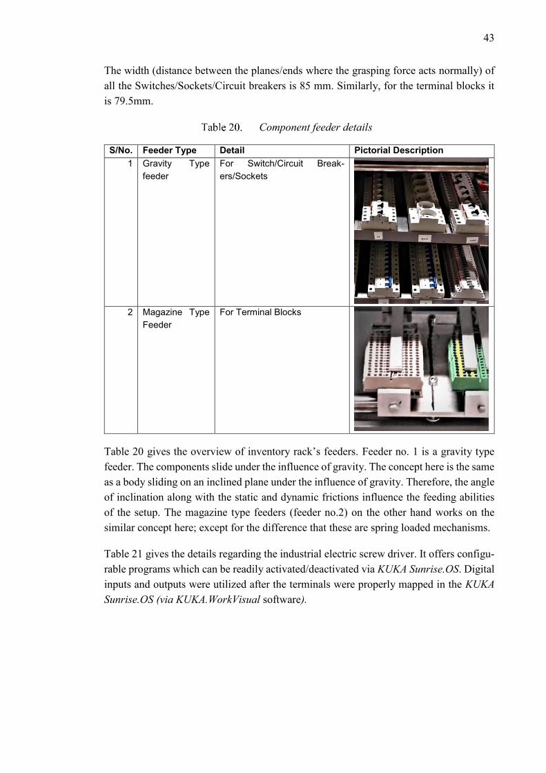
43
The width (distance between the planes/ends where the grasping force acts normally) of
all the Switches/Sockets/Circuit breakers is 85 mm. Similarly, for the terminal blocks it
is 79.5mm.
Component feeder details
S/No. Feeder Type Detail Pictorial Description
1 Gravity Type
feeder
For Switch/Circuit Break-
ers/Sockets
2 Magazine Type
Feeder
For Terminal Blocks
Table 20 gives the overview of inventory rack’s feeders. Feeder no. 1 is a gravity type
feeder. The components slide under the influence of gravity. The concept here is the same
as a body sliding on an inclined plane under the influence of gravity. Therefore, the angle
of inclination along with the static and dynamic frictions influence the feeding abilities
of the setup. The magazine type feeders (feeder no.2) on the other hand works on the
similar concept here; except for the difference that these are spring loaded mechanisms.
Table 21 gives the details regarding the industrial electric screw driver. It offers configu-
rable programs which can be readily activated/deactivated via KUKA Sunrise.OS. Digital
inputs and outputs were utilized after the terminals were properly mapped in the KUKA
Sunrise.OS (via KUKA.WorkVisual software).
44
Industrial electric screwdriver details
Item Detail Pictorial Description
Kolver EDU 2AE/TOP
Electric screw driver
8 configurable
programmes
for fastening
applications
The aluminum cased screwdriver is housed in a 3D printed carbon fiber case. This ensures
it to be grasped by the robot’s gripper without damaging it. The screw driver programs
offer a variety of configurable parameters e.g. Torque, Speed, number of allowed rejects
etc. [26]
5.4 Collaborative Assembly Tests
A total of three tests were carried out to determine the collaborative assembly cycle times
with the task assignments given in Table 22. Moreover, the DFA methodology-based
worksheets for these tests are given in ‘APPENDIX B’ for detailed study.
Task assignment between Human and the Robot
S/No. Component Phase Task Assignment
1 DIN rail 1 Human
2 Terminal Block: ZDU 2.5/4AN (Grey) 2 Human
3 Terminal Block: ZDU 2.5/4AN (Grey) 2 Human
4 Terminal Block: ZDU 2.5/4AN BL 2 Human
5 Terminal Block: ZDU 2.5/4AN BL 2 Human
6 Terminal Block: ZPE 2.5/4AN (GREEN) 2 Human
7 Terminal Block: ZPE 2.5/4AN (GREEN) 2 Human
8 Terminal Block: ZDU 2.5/4AN (Grey) 2 Human
9 Terminal Block: ZDU 2.5/4AN (Grey) 2 Human
10 Terminal Block: ZDU 2.5/4AN BL 2 Human
45
11 Terminal Block: ZDU 2.5/4AN BL 2 Human
12 Terminal Block: ZPE 2.5/4AN (GREEN) 2 Human
13 Terminal Block: ZPE 2.5/4AN (GREEN) 2 Human
14 ABB FH202 A 2 COBOT
15 CHINT C6 2 COBOT
16 CHINT D6 2 COBOT
17 ABB D2 2 COBOT
18 Wire Set: KM51062820G10135 3 Human + COBOT
19 Wire Set: KM796121G12106 3 Human + COBOT
20 Wire Set: KM51042524G14 3 Human + COBOT
21 CHINT B6 4 COBOT
22 CHINT B10 4 COBOT
23 ABB Socket 4 COBOT
24 ABB E251-230 4 COBOT
25 ABB E216 4 COBOT
26 Labels 4 Human
These task assignments are based on the product analysis. The analysis was based on the
findings of assembly stage decomposition model and DFA analysis. Phase 1 is carried
out by the human assembly worker. Terminal block assembly of Phase 2 is carried out by
the human assembly worker alongside COBOT. COBOT here assembles the
Switch/Socket/Circuit breakers in between the terminal blocks. Phase 3 is carried out to-
gether by the human and the COBOT. As mentioned earlier, the COBOT in compliant
mode assists the human assembly worker in securing wire connections. During Phase 4,
the COBOT assembles the rest of the electrical components; whereas, the human assem-
bly worker puts the labels on the already assembled components. From the tests (given
next) it is clear that the cycle times range from 3.0 – 4.0 min. Therefore, the demand of
113 Units/Day can be reached since the Takt time for it is 3.98 min; as presented in the
case study. And to reach the highest mentioned demand of 210 Units/Day, the available
resources can be doubled.
5.4.1 First Test
The Cartesian velocities of the TCP frame along with stiffness values, for complaint
mode, have been given in Table 23.
Details of the collaborative assembly
S/No. Type Value
1 Maximum Cartesian velocity of the TCP
225 mm/s
2 Cartesian Velocity of the TCP during Linear motions
50 mm/s
3 Stiffness Values of TCP’s Z - axis 1000 N/m
46
Maximum Cartesian velocity of the TCP was set in KUKA Sunrise Workbench’s safety
configuration by utilizing configurable customer safety configuration. Whereas, the Car-
tesian velocity of the TCP frame during linear motions, along with the stiffness values,
were set in the script of Offline Robot Programme. Since the z-axis of the TCP frame is
utilized by the end effector to approach or retract during the linear motions; therefore, it
is set soft in this direction. The allowable values of stiffness (For x, y and z axis) range
from 0 - 5000 N/m. By analyzing Program 2, it is clear that the linear end effector velocity
is adjusted to 50 mm/s; by reducing the set speed to 50% of its actual designated value.
Human Robot Collaborative Assembly timings
S/No. Phase Human Robot Total Phase Timings
(s)
Total Assembly time (min) Time (s)
1 1 5 N/A 5
3.88
2 2 60 81.8 81.8
3 3 45 45
4 4 60 101.2 101.2
5.4.2 Second Test
Similarly, for the second test, the maximum TCP velocities were assigned along with the
stiffness values. And these are given in Table 25.
Details of the collaborative assembly
S/No. Type Value
1 Maximum Cartesian velocity of the TCP
225 mm/s
2 Cartesian Velocity of the TCP during Linear motions
112.5 mm/s
3 Stiffness Value of TCP’s Z - axis 1000 N/m
From Table 26, it can be seen that by increasing the Cartesian speeds, during the linear
motions, the total assembly cycle time has reduced to 3.598 min.
2
4
6
lbr_Iiwa.getApplicationControl().setApplicationOverride(0.5); /* Speed reduced by 50% */ gripper_1.move(lin(Frame_orient).setCartVelocity(100)); /* For moving the end effector (gripper_1) with maximum Cartesian velocity of 50 mm/sec */
Program 2. Application override function to set the Cartesian velocity of the TCP
Table 24 shows that the total assembly time is 3.88 min. This is the sum total of all the
phase timings. Total phase timing is dependent on the bottlenecks. For instance, during
phase 2, the COBOT has the higher cycle time; therefore, the total phase 2 time is taken
to be that of the COBOT i.e. 81.8 s.
47
Human Robot Collaborative Assembly timings
S/No. Phase Human Robot Total Phase Timings
(s)
Total Assembly time (min) Time (s)
1 1 5 N/A 5
3.598 2 2 60 74.91 74.91
3 3 45 45
4 4 60 90.96 90.96
5.4.3 Third Test
For the third test, the linear velocity of the TCP was increased to 225 mm/s (shown in
Table 27). The stiffness value of the TCP frame was, however, lowered to avoid any
hazard. This reduces the delivered kinetic energy of the end effector. The idea here is to
lower down the inertial properties of the manipulator (kinematic chain including end ef-
fector and its load) in case of increase in speed.
Details of the collaborative assembly
S/No. Type Value in mm/s
1 Maximum Cartesian velocity of the TCP
225 mm/s
2 Cartesian Velocity of the TCP during Linear motions
225 mm/s
3 Stiffness Value of TCP’s Z - axis 800 N/m
From Table 28 it can be seen that by doing so the total assembly cycle time has been
reduced to 3.332 min.
Human Robot Collaborative Assembly timings
S/No. Phase Human Robot Total Phase Timings
(s)
Total Assembly time (min) Time (s)
1 1 5 N/A 5
3.332 2 2 60 69.6 69.6
3 3 45 45
4 4 60 80.33 80.33
5.4.4 Operator oriented application design
During the development of this thesis, hand guided frame teaching methodology was uti-
lized for the design of collaborative applications. This relieves the human assembly
worker of having the need to be an expert in the programming related knowledge areas.
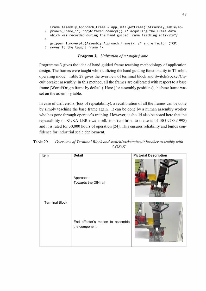
48
Programme 3 gives the idea of hand guided frame teaching methodology of application
design. The frames were taught while utilizing the hand guiding functionality in T1 robot
operating mode. Table 29 gives the overview of terminal block and Switch/Socket/Cir-
cuit breaker assembly. In this method, all the frames are calibrated with respect to a base
frame (World/Origin frame by default). Here (for assembly positions), the base frame was
set on the assembly table.
In case of drift errors (loss of repeatability), a recalibration of all the frames can be done
by simply teaching the base frame again. It can be done by a human assembly worker
who has gone through operator’s training. However, it should also be noted here that the
repeatability of KUKA LBR iiwa is ±0.1mm (confirms to the tests of ISO 9283:1998)
and it is rated for 30,000 hours of operation [24]. This ensures reliability and builds con-
fidence for industrial scale deployment.
Overview of Terminal Block and switch/socket/circuit breaker assembly with
COBOT
Item Detail Pictorial Description
Terminal Block
Approach
Towards the DIN rail
End effector’s motion to assemble
the component.
2
4
6
Frame Assembly_Approach_Frame = app_Data.getFrame("/Assembly_Table/ap-proach_Frame_1").copyWithRedundancy(); /* acquiring the frame data which was recorded during the hand guided frame teaching activity*/ gripper_1.move(ptp(Assembly_Approach_Frame)); /* end effector (TCP) moves to the taught frame */
Program 3. Utilization of a taught frame
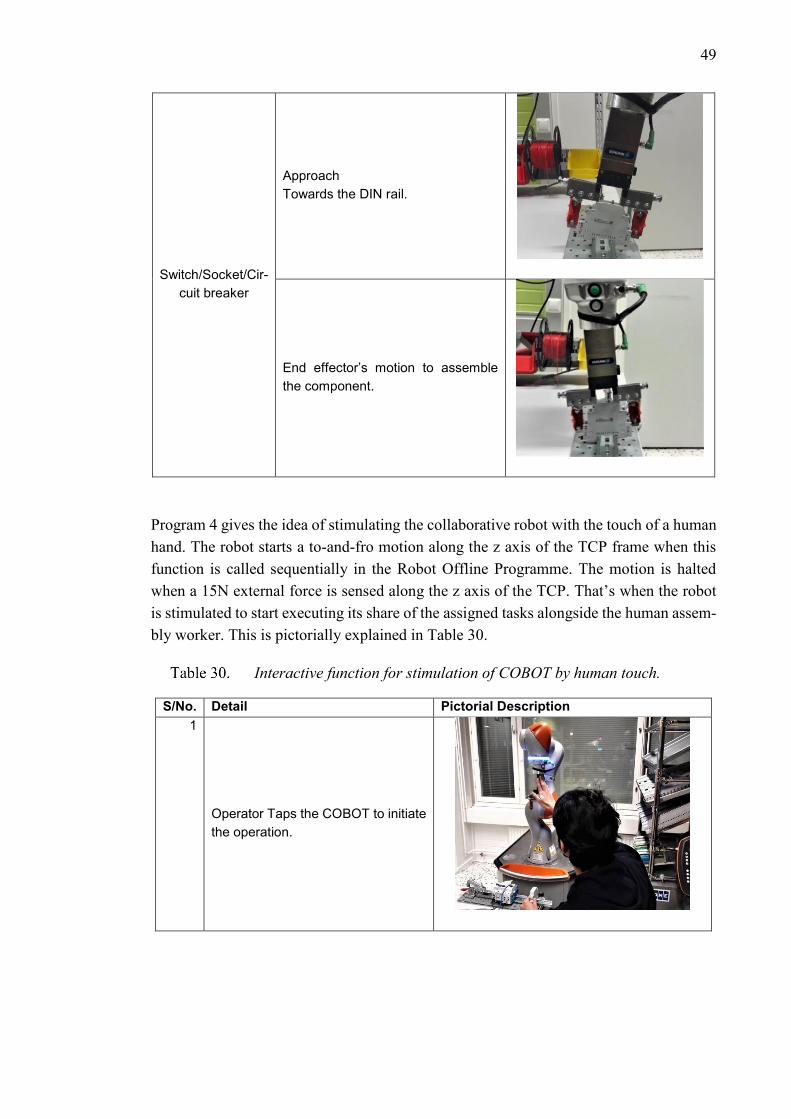
49
Switch/Socket/Cir-
cuit breaker
Approach
Towards the DIN rail.
End effector’s motion to assemble
the component.
Program 4 gives the idea of stimulating the collaborative robot with the touch of a human
hand. The robot starts a to-and-fro motion along the z axis of the TCP frame when this
function is called sequentially in the Robot Offline Programme. The motion is halted
when a 15N external force is sensed along the z axis of the TCP. That’s when the robot
is stimulated to start executing its share of the assigned tasks alongside the human assem-
bly worker. This is pictorially explained in Table 30.
Interactive function for stimulation of COBOT by human touch.
S/No. Detail Pictorial Description
1
Operator Taps the COBOT to initiate
the operation.
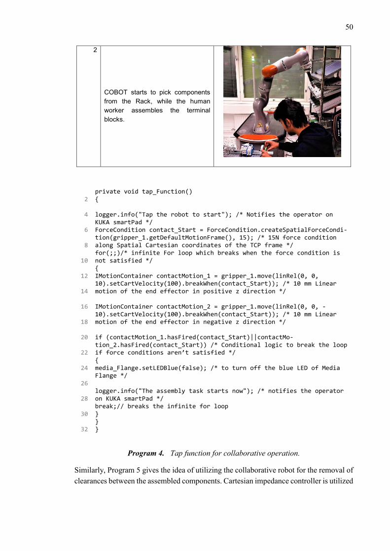
50
2
COBOT starts to pick components
from the Rack, while the human
worker assembles the terminal
blocks.
Similarly, Program 5 gives the idea of utilizing the collaborative robot for the removal of
clearances between the assembled components. Cartesian impedance controller is utilized
2
4
6
8
10
12
14
16
18
20
22
24
26
28
30
32
private void tap_Function() { logger.info("Tap the robot to start"); /* Notifies the operator on KUKA smartPad */ ForceCondition contact_Start = ForceCondition.createSpatialForceCondi-tion(gripper_1.getDefaultMotionFrame(), 15); /* 15N force condition along Spatial Cartesian coordinates of the TCP frame */ for(;;)/* infinite For loop which breaks when the force condition is not satisfied */ { IMotionContainer contactMotion_1 = gripper_1.move(linRel(0, 0, 10).setCartVelocity(100).breakWhen(contact_Start)); /* 10 mm Linear motion of the end effector in positive z direction */ IMotionContainer contactMotion_2 = gripper_1.move(linRel(0, 0, -10).setCartVelocity(100).breakWhen(contact_Start)); /* 10 mm Linear motion of the end effector in negative z direction */ if (contactMotion_1.hasFired(contact_Start)||contactMo-tion_2.hasFired(contact_Start)) /* Conditional logic to break the loop if force conditions aren’t satisfied */ { media_Flange.setLEDBlue(false); /* to turn off the blue LED of Media Flange */ logger.info("The assembly task starts now"); /* notifies the operator on KUKA smartPad */ break;// breaks the infinite for loop } } }
Program 4. Tap function for collaborative operation.

51
to lower the stiffness along y-axis (direction of linear motion) of the TCP frame. Carte-
sian Impedance controller allows deviation from the set path when the motion is ob-
structed due to the presence of DIN rail components. The TCP does not reach the end
frame while moving linearly from the start frame. But it tries to do it by pushing against
the obstructions. The linear motion is discontinued if the external force along the TCP
frame reaches the set threshold of 90N. The start and end frame are represented by point
A and B in Table 31 respectively.
Programmed functionality for removing the clearances between the assembled
components.
S/No. Detail Pictorial Description
1
The COBOT’s end effector moves linearly
from point A to point B to remove the
clearances between the assembled
components.
2
4
6
8
10
11
12
14
16
private void remove_Clearance() { CartesianImpedanceControlMode clearancerob_Push = new CartesianImped-anceControlMode(); /* Instantiating the class to specify the control mode */ ForceCondition external_React_Force = ForceCondition.createSpatial-ForceCondition(gripper_1.getDefaultMotionFrame(), 90);/* 90N force condition along the Spatial Cartesian coordinates of the TCP frame */ clearancerob_Push.parametrize(CartDOF.Y).setStiffness(500.0); /* To set stiffness values for Y-Axis of the TCP */ Frame push_Comp_Orient= app_Data.getFrame("/Assembly_Table/ori-ent_Push_Comp").copyWithRedundancy(); /* frame to orient the end ef-fector */
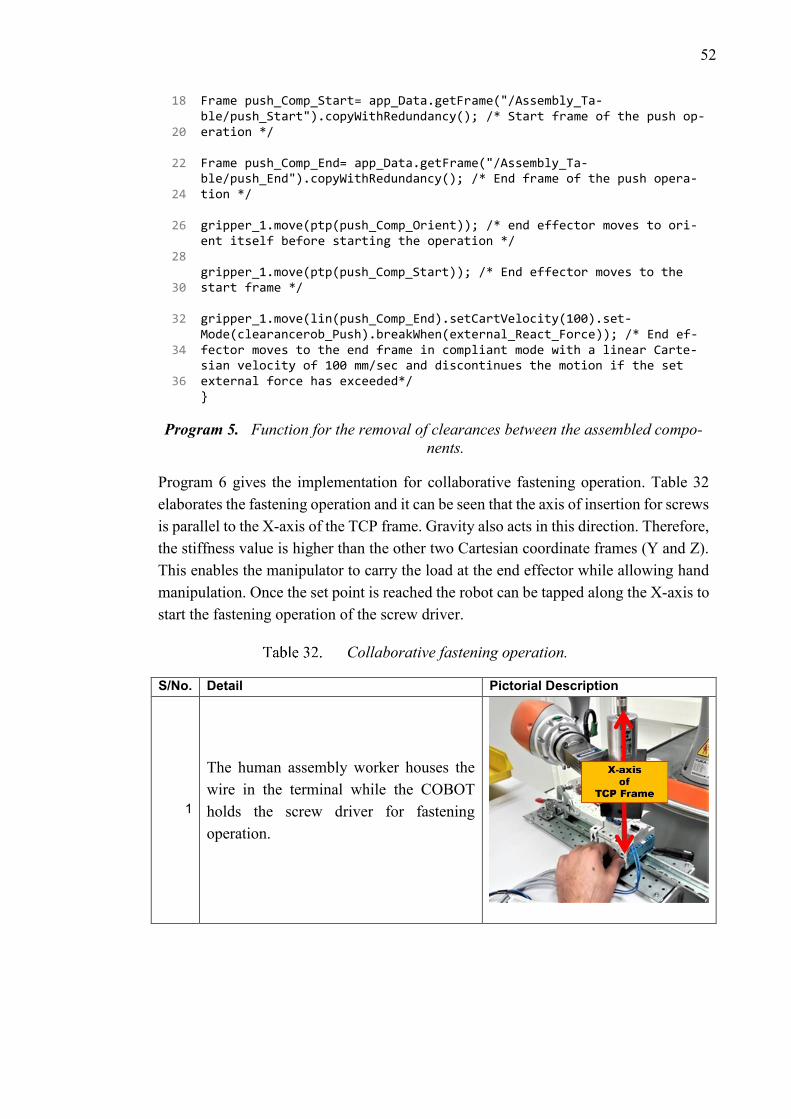
52
18
20
22
24
26
28
30
32
34
36
Frame push_Comp_Start= app_Data.getFrame("/Assembly_Ta-ble/push_Start").copyWithRedundancy(); /* Start frame of the push op-eration */ Frame push_Comp_End= app_Data.getFrame("/Assembly_Ta-ble/push_End").copyWithRedundancy(); /* End frame of the push opera-tion */ gripper_1.move(ptp(push_Comp_Orient)); /* end effector moves to ori-ent itself before starting the operation */ gripper_1.move(ptp(push_Comp_Start)); /* End effector moves to the start frame */ gripper_1.move(lin(push_Comp_End).setCartVelocity(100).set-Mode(clearancerob_Push).breakWhen(external_React_Force)); /* End ef-fector moves to the end frame in compliant mode with a linear Carte-sian velocity of 100 mm/sec and discontinues the motion if the set external force has exceeded*/ }
Program 5. Function for the removal of clearances between the assembled compo-
nents.
Program 6 gives the implementation for collaborative fastening operation. Table 32
elaborates the fastening operation and it can be seen that the axis of insertion for screws
is parallel to the X-axis of the TCP frame. Gravity also acts in this direction. Therefore,
the stiffness value is higher than the other two Cartesian coordinate frames (Y and Z).
This enables the manipulator to carry the load at the end effector while allowing hand
manipulation. Once the set point is reached the robot can be tapped along the X-axis to
start the fastening operation of the screw driver.
Collaborative fastening operation.
S/No. Detail Pictorial Description
1
The human assembly worker houses the
wire in the terminal while the COBOT
holds the screw driver for fastening
operation.
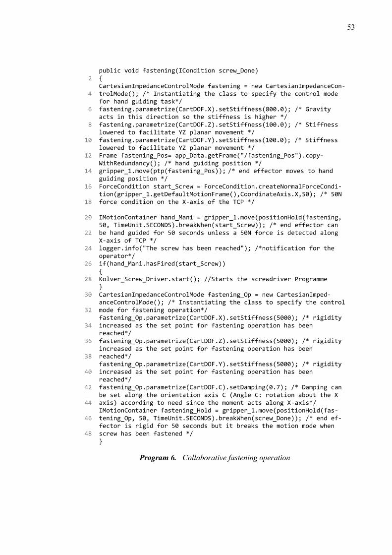
53
2
4
6
8
10
12
14
16
18
20
22
24
26
28
30
32
34
36
38
40
42
44
46
48
public void fastening(ICondition screw_Done) { CartesianImpedanceControlMode fastening = new CartesianImpedanceCon-trolMode(); /* Instantiating the class to specify the control mode for hand guiding task*/ fastening.parametrize(CartDOF.X).setStiffness(800.0); /* Gravity acts in this direction so the stiffness is higher */ fastening.parametrize(CartDOF.Z).setStiffness(100.0); /* Stiffness lowered to facilitate YZ planar movement */ fastening.parametrize(CartDOF.Y).setStiffness(100.0); /* Stiffness lowered to facilitate YZ planar movement */ Frame fastening_Pos= app_Data.getFrame("/fastening_Pos").copy-WithRedundancy(); /* hand guiding position */ gripper_1.move(ptp(fastening_Pos)); /* end effector moves to hand guiding position */ ForceCondition start_Screw = ForceCondition.createNormalForceCondi-tion(gripper_1.getDefaultMotionFrame(),CoordinateAxis.X,50); /* 50N force condition on the X-axis of the TCP */ IMotionContainer hand_Mani = gripper_1.move(positionHold(fastening, 50, TimeUnit.SECONDS).breakWhen(start_Screw)); /* end effector can be hand guided for 50 seconds unless a 50N force is detected along X-axis of TCP */ logger.info("The screw has been reached"); /*notification for the operator*/ if(hand_Mani.hasFired(start_Screw)) { Kolver_Screw_Driver.start(); //Starts the screwdriver Programme } CartesianImpedanceControlMode fastening_Op = new CartesianImped-anceControlMode(); /* Instantiating the class to specify the control mode for fastening operation*/ fastening_Op.parametrize(CartDOF.X).setStiffness(5000); /* rigidity increased as the set point for fastening operation has been reached*/ fastening_Op.parametrize(CartDOF.Z).setStiffness(5000); /* rigidity increased as the set point for fastening operation has been reached*/ fastening_Op.parametrize(CartDOF.Y).setStiffness(5000); /* rigidity increased as the set point for fastening operation has been reached*/ fastening_Op.parametrize(CartDOF.C).setDamping(0.7); /* Damping can be set along the orientation axis C (Angle C: rotation about the X axis) according to need since the moment acts along X-axis*/ IMotionContainer fastening_Hold = gripper_1.move(positionHold(fas-tening_Op, 50, TimeUnit.SECONDS).breakWhen(screw_Done)); /* end ef-fector is rigid for 50 seconds but it breaks the motion mode when screw has been fastened */ }
Program 6. Collaborative fastening operation
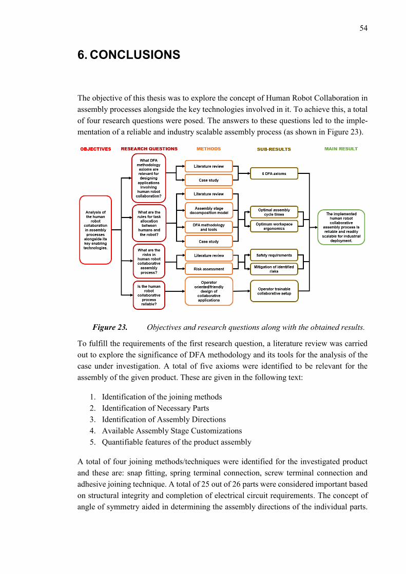
54
6. CONCLUSIONS
The objective of this thesis was to explore the concept of Human Robot Collaboration in
assembly processes alongside the key technologies involved in it. To achieve this, a total
of four research questions were posed. The answers to these questions led to the imple-
mentation of a reliable and industry scalable assembly process (as shown in Figure 23).
Figure 23. Objectives and research questions along with the obtained results.
To fulfill the requirements of the first research question, a literature review was carried
out to explore the significance of DFA methodology and its tools for the analysis of the
case under investigation. A total of five axioms were identified to be relevant for the
assembly of the given product. These are given in the following text:
1. Identification of the joining methods
2. Identification of Necessary Parts
3. Identification of Assembly Directions
4. Available Assembly Stage Customizations
5. Quantifiable features of the product assembly
A total of four joining methods/techniques were identified for the investigated product
and these are: snap fitting, spring terminal connection, screw terminal connection and
adhesive joining technique. A total of 25 out of 26 parts were considered important based
on structural integrity and completion of electrical circuit requirements. The concept of
angle of symmetry aided in determining the assembly directions of the individual parts.
55
It was utilized in planning the assembly sequence and helped in avoiding confusing/un-
certain situations for the human assembly worker. It was also utilized in the preparation
of the Robot Offline Programme. Unwanted and extra robotic movements, which only
add to the overall entropy of the assembly process, were effectively avoided. This was
the result of careful evaluation of the assembly orientation requirements of the individual
parts. Availability of the assembly stage customizations offered room for the execution
of collaborative tasks. Two-digit manual assembly codes were generated to aid the man-
ual assembly of the parts. These were used to increase the awareness/alertness of the as-
sembly worker during the collaborative operations.
The second research question emphasizes on the rules of task assignment between the
human assembly worker and the collaborative robot. Task Assignments between the hu-
man and the robot was explored with the following objectives in mind: Optimal assembly
cycle times and workspace ergonomics. Literature review facilitated in understanding the
needs and concept of HRC. The given product was disintegrated to produce the assembly
stage decomposition model. It outlined the phases of assembly alongside the added fea-
tures/components of the given product. Next, DFA methodology axioms and tools were
used to analyze the different phases of the product assembly outlined in the assembly
stage decomposition model. 3 out of 4 phases of assembly offered room for collaborative
activities between the human and the collaborative robot. The resulting task assignments
ensured optimal assembly cycle times and ergonomic operations. The assembly cycle
times corresponded with the customer demands presented in the case study of the given
product. Different functionalities were added in the Robot Offline Program which ensured
an ergonomic assembly process. One of these functionalities involved the robot being
stimulated by the touch of the human coworker. Another function allowed the robot to
dissipate the unwanted vibrational energy of the industrial screw driver via virtual
damper; thus, allowing the human coworker to avoid wrist sprains. It was implemented
as part of the compliant behavior of the robot at the TCP frame. The collaborative robot
also removed the clearances between the assembled components by pushing against them
in compliant mode. These functionalities were readily available (sequential function call
when needed) for the human assembly worker during the collaborative assembly process.
From the results of the collaborative tests it is evident that the robot always had the higher
cycle time during the collaborative tasks. This allowed the human worker to have extra
available time while keeping up with the customer demands.
The third research question dealt with the hazards involved in a collaborative assembly
operation. Literature review facilitated in instilling awareness alongside necessary
knowledge regarding the safety requirements of the collaborative assembly processes.
Risk assessment was performed (according to ISO12100) before commissioning the la-
boratory setup for collaborative assembly. A total of seven use cases were identified along
with their associated risks and hazards. Strategies for the mitigation of the identified risks
were then formulated and applied during the development of this thesis.

56
The last research question deals with the reliability of the collaborative process. Operator
oriented/friendly approach was taken during the preparation of Robot Offline Program.
Hand-guided frame teaching methodology was used during the development of the ro-
botic applications. Apart from this, the collaborative robot is, inherently, rated for 30,000
hours of operation with an accuracy of ±0.1mm. However, in case of drift errors, the
collaborative system can be readily trained again by the human coworker; to resume the
normal collaborative assembly operation.
To conclude, it can be stated that the results, obtained while addressing the research ques-
tions, ensured a reliable and industry scalable implementation of the human robot collab-
orative assembly process.
57
7. FUTURE DEVELOPMENTS
There are several steps that could be taken to delve deeper into the topic of Human robot
collaborative assembly process. One of them involves mapping of external sensors in
KUKA SUNRISE.OS to increase safety and productivity. For instance, the use of 3D
perception devices to detect human presence and adjustment of manipulator’s speed ac-
cordingly; to ensure safe and productive operations.
Another future development would be to test the collaborative assembly process for the
biomechanical limit criterions presented in ISO/TS 15066. Determination of ergonomic
and psychological aspects of human robot collaborative assembly also offers a lot of room
for R&D related to the topic.
Development of a motion planner/visualization platform, that readily generates the Robot
Offline Programme, could ease the COBOT commissioning process. In this case, a frame
parser needs to be developed which transfers the frames along with redundancy infor-
mation from the planning software to the KUKA SUNRISE.OS.
58
REFERENCES
[1] International Organization for Standardization, "ISO 10218-2:2011 Robots and
robotic devices -- Safety requirements for industrial robots -- Part 2: Robot systems
and integration," [Online]. Available: https://www.iso.org/standard/41571.html.
[2] KUKA Roboter GmbH, KUKA Sunrise.OS 1.11 KUKA Sunrise.Workbench 1.11
Operating and Programming Instructions for System Integrators, 2016.
[3] K. Schwab, "The Fourth Industrial Revolution: what it means, how to respond,"
World Economic Forum, [Online]. Available:
https://www.weforum.org/agenda/2016/01/the-fourth-industrial-revolution-what-
it-means-and-how-to-respond/. [Accessed 18 July 2018].
[4] European Commission, "What is an SME?," 01 November 2018. [Online].
Available: http://ec.europa.eu/growth/smes/business-friendly-environment/sme-
definition_en.
[5] M. Bortolini, E. Ferrari, M. Gamberi, F. Pilati and M. Faccio, "Assembly system
design in the Industry 4.0 era: a general framework," IFAC-PapersOnLine, vol. 50,
no. 1, pp. 5700-5705, 2017.
[6] euRobotics aisbl, "Robotics 2020 Strategic Research Agenda for Robotics in
Europe," 11 October 2013. [Online]. Available:
https://ec.europa.eu/research/industrial_technologies/pdf/robotics-ppp-
roadmap_en.pdf.
[7] Björn Matthias, ABB Corporate Research, "Risk Assessment for Human-Robot
Collaborative Applications," in Workshop IROS 2015 – Physical Human-Robot
Collaboration: Safety, Control, Learning and Applications, 2015.
[8] R. J. Halme, M. Lanz, J. Kämäräinen, R. Pieters, J. Latokartano and A. Hietanen,
"Review of vision-based safety systems for human-robot collaboration," Procedia
CIRP, vol. 72, pp. 111-116, 2018.
[9] International Organization for Standardization, "ISO 10218-1:2011 Robots and
robotic devices -- Safety requirements for industrial robots -- Part 1: Robots,"
[Online]. Available: https://www.iso.org/standard/51330.html.
59
[10] KUKA Systems GmbH, Blücherstraße 144, 86165 Augsburg, Germany, "KUKA
flexFELLOW," 2018. [Online]. Available: https://www.kuka.com/en-
de/products/mobility/mobile-robots/kuka-flexfellow. [Accessed 13 October 2018].
[11] International Organization for Standardization, "ISO/TS 15066:2016 Robots and
robotic devices -- Collaborative robots," February 2016. [Online]. Available:
https://www.iso.org/standard/62996.html.
[12] S. Fox, A. Kotelba and . I. Niskanen, "Cognitive Factories: Modeling Situated
Entropy in Physical Work Carried Out by Humans and Robots," Entropy, vol. 20,
no. 9, 2018.
[13] VTT Technical Research Centre of Finland Ltd., , "Guidelines to make safe
industrial robot systems," Tampere, 2017.
[14] European Commission, "Regulations, Directives and other acts," [Online].
Available: https://europa.eu/european-union/eu-law/legal-acts_en. [Accessed 24
September 2018].
[15] American National Standards Institute (ANSI), "ISO Type A-B-C Structure for
Machinery Standards," [Online]. Available: https://blog.ansi.org/2017/10/iso-type-
abc-structure-machinery-standards-ansi-b11/#gref. [Accessed 24 September 2018].
[16] M. Lanz, R. V. Osuna and R. Tuokko, "FEATURE-BASED MODELING AND
ANALYSIS FOR KNOWLEDGE INTENSIVE CONCURRENT ENGINEERING
IN FINAL ASSEMBLY," in Proceedings of The 6th International Conference on
Computer-Aided Industrial Design & Conceptua l Design (CAID&CD 2005),
Applications of digital techniques in industrial design engineering CAID&CD,
Delft, the Netherlands., 2005.
[17] G. Boothroyd, Assembly Automation and Product Design, Second Edition., CRC
Press, 2005 .
[18] G. Boothroyd, P. Dewhurst and W. A. Knight, Product Design for Manufacture and
Assembly, Third Edition., CRC Press, 2010.
[19] G. A. Chang and W. R. Peterson, "Using Design for Assembly Methodology to
Improve Product Development and Design Learning at MSU," American Society
of Engineering Education., 2012.
60
[20] KONE Corporation, "Visual components - Tool for 3D Simulation and
Manufacturing," in 3D Simulation seminar by Visual Components and Delfoi,
Espoo, 2018.
[21] KONE Industrial Oy, "SWITCH-moduulin VALMISTUSOHJE," Hyvinkää, FI.,
2018.
[22] KUKA Roboter GmbH, "14.10.1 Redundancy angle," in KUKA Sunrise.OS 1.11
KUKA Sunrise.Workbench 1.11 Operating and Programming Instructions for
System Integrators, pp. 320-321.
[23] B. Siciliano, L. Sciavicco , L. Villani and G. Oriolo, in Robotics Modelling,
Planning and Control , Springer-Verlag London Limited 2010 .
[24] P. Cazottes, "Compliant mechanisms," Institut Jean le Rond d'Alembert, Universite
Pierre et Marie Curie, [Online]. Available:
http://www.lmm.jussieu.fr/~cazottes/Compliant_mechanisms.html.
[25] International Organization for Standardization, "ISO 12100:2010 Safety of
machinery -- General principles for design -- Risk assessment and risk reduction,"
[Online]. Available: https://www.iso.org/standard/51528.html.
[26] Kolver srl via M. Corner, 19/21 36016 Thiene (VI) - Italy, "Controllers EDU
series," [Online]. Available: https://kolver.it/products-list/8-Controllers-EDU-
series.
[27] European Commission, "Directive 2006/42/EC of the European Parliament and of
the Council of 17 May 2006 on machinery, and amending Directive 95/16/EC
(recast) (Text with EEA relevance)," Official Journal of the European Union, 2006.
[28] C. Ott, "Cartesian Impedance Control of Redundant and Flexible-Joint Robots,"
Springer Tracts in Advanced Robotics, vol. 49, 2008.
[29] Statistics Finland, Työpajankatu 13, FI-00580 Helsinki., "Wages, Salaries and
Labour Costs," 2 October 2018. [Online]. Available:
https://www.stat.fi/tup/suoluk/suoluk_palkat_en.html. [Accessed 23 10 2018].
[30] Weidmüller Interface GmbH & Co. KG, "Spring connection with tension clamp
technology," [Online]. Available:
https://www.weidmueller.com/int/products/connectivity/klippon--connect-
terminal-blocks/universal-range/spring-connection-with-tension-clamp-
technology.

61
[31] KUKA Deutschland GmbH, Zugspitzstraße 140, 86165 Augsburg, Germany, "LBR
iiwa," [Online]. Available: https://www.kuka.com/en-de/products/robot-
systems/industrial-robots/lbr-iiwa.
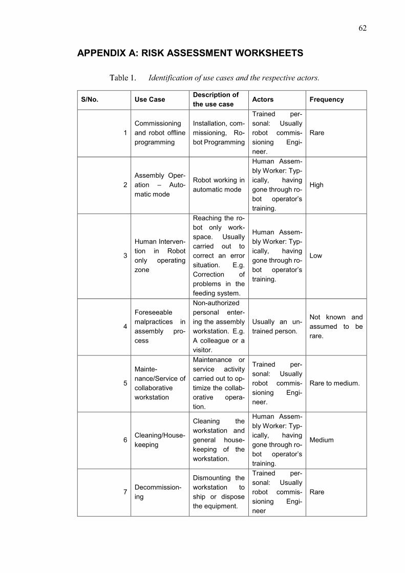
62
APPENDIX A: RISK ASSESSMENT WORKSHEETS
Identification of use cases and the respective actors.
S/No. Use Case Description of
the use case Actors Frequency
1
Commissioning
and robot offline
programming
Installation, com-
missioning, Ro-
bot Programming
Trained per-
sonal: Usually
robot commis-
sioning Engi-
neer.
Rare
2
Assembly Oper-
ation – Auto-
matic mode
Robot working in
automatic mode
Human Assem-
bly Worker: Typ-
ically, having
gone through ro-
bot operator’s
training.
High
3
Human Interven-
tion in Robot
only operating
zone
Reaching the ro-
bot only work-
space. Usually
carried out to
correct an error
situation. E.g.
Correction of
problems in the
feeding system.
Human Assem-
bly Worker: Typ-
ically, having
gone through ro-
bot operator’s
training.
Low
4
Foreseeable
malpractices in
assembly pro-
cess
Non-authorized
personal enter-
ing the assembly
workstation. E.g.
A colleague or a
visitor.
Usually an un-
trained person.
Not known and
assumed to be
rare.
5
Mainte-
nance/Service of
collaborative
workstation
Maintenance or
service activity
carried out to op-
timize the collab-
orative opera-
tion.
Trained per-
sonal: Usually
robot commis-
sioning Engi-
neer.
Rare to medium.
6 Cleaning/House-
keeping
Cleaning the
workstation and
general house-
keeping of the
workstation.
Human Assem-
bly Worker: Typ-
ically, having
gone through ro-
bot operator’s
training.
Medium
7 Decommission-
ing
Dismounting the
workstation to
ship or dispose
the equipment.
Trained per-
sonal: Usually
robot commis-
sioning Engi-
neer
Rare
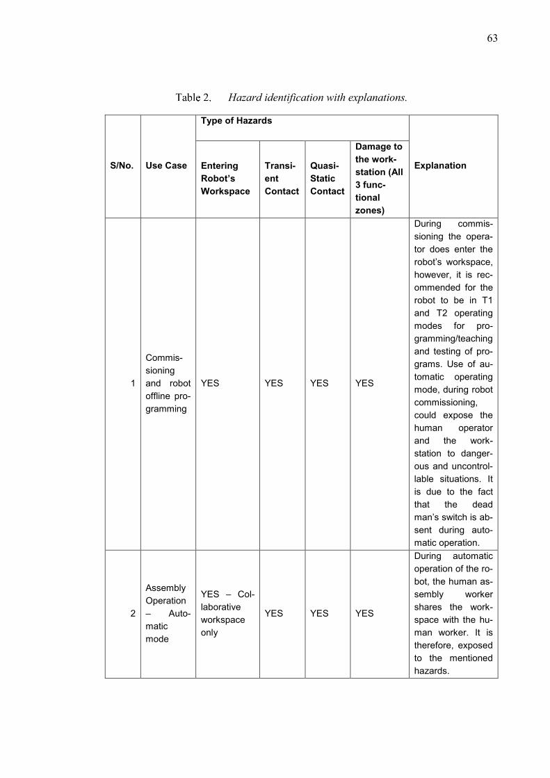
63
Hazard identification with explanations.
S/No. Use Case
Type of Hazards
Explanation Entering
Robot’s
Workspace
Transi-
ent
Contact
Quasi-
Static
Contact
Damage to
the work-
station (All
3 func-
tional
zones)
1
Commis-
sioning
and robot
offline pro-
gramming
YES YES YES YES
During commis-
sioning the opera-
tor does enter the
robot’s workspace,
however, it is rec-
ommended for the
robot to be in T1
and T2 operating
modes for pro-
gramming/teaching
and testing of pro-
grams. Use of au-
tomatic operating
mode, during robot
commissioning,
could expose the
human operator
and the work-
station to danger-
ous and uncontrol-
lable situations. It
is due to the fact
that the dead
man’s switch is ab-
sent during auto-
matic operation.
2
Assembly
Operation
– Auto-
matic
mode
YES – Col-
laborative
workspace
only
YES YES YES
During automatic
operation of the ro-
bot, the human as-
sembly worker
shares the work-
space with the hu-
man worker. It is
therefore, exposed
to the mentioned
hazards.
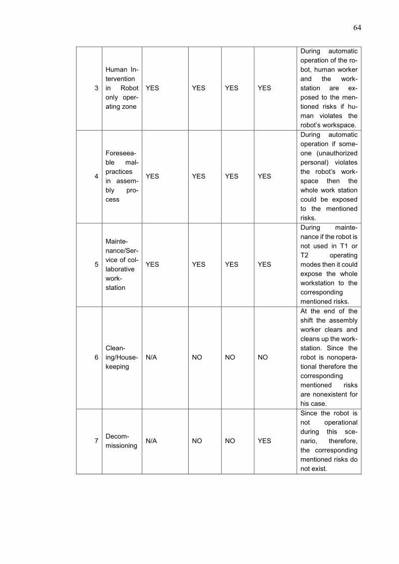
64
3
Human In-
tervention
in Robot
only oper-
ating zone
YES YES YES YES
During automatic
operation of the ro-
bot, human worker
and the work-
station are ex-
posed to the men-
tioned risks if hu-
man violates the
robot’s workspace.
4
Foreseea-
ble mal-
practices
in assem-
bly pro-
cess
YES YES YES YES
During automatic
operation if some-
one (unauthorized
personal) violates
the robot’s work-
space then the
whole work station
could be exposed
to the mentioned
risks.
5
Mainte-
nance/Ser-
vice of col-
laborative
work-
station
YES YES YES YES
During mainte-
nance if the robot is
not used in T1 or
T2 operating
modes then it could
expose the whole
workstation to the
corresponding
mentioned risks.
6
Clean-
ing/House-
keeping
N/A NO NO NO
At the end of the
shift the assembly
worker clears and
cleans up the work-
station. Since the
robot is nonopera-
tional therefore the
corresponding
mentioned risks
are nonexistent for
his case.
7 Decom-
missioning N/A NO NO YES
Since the robot is
not operational
during this sce-
nario, therefore,
the corresponding
mentioned risks do
not exist.
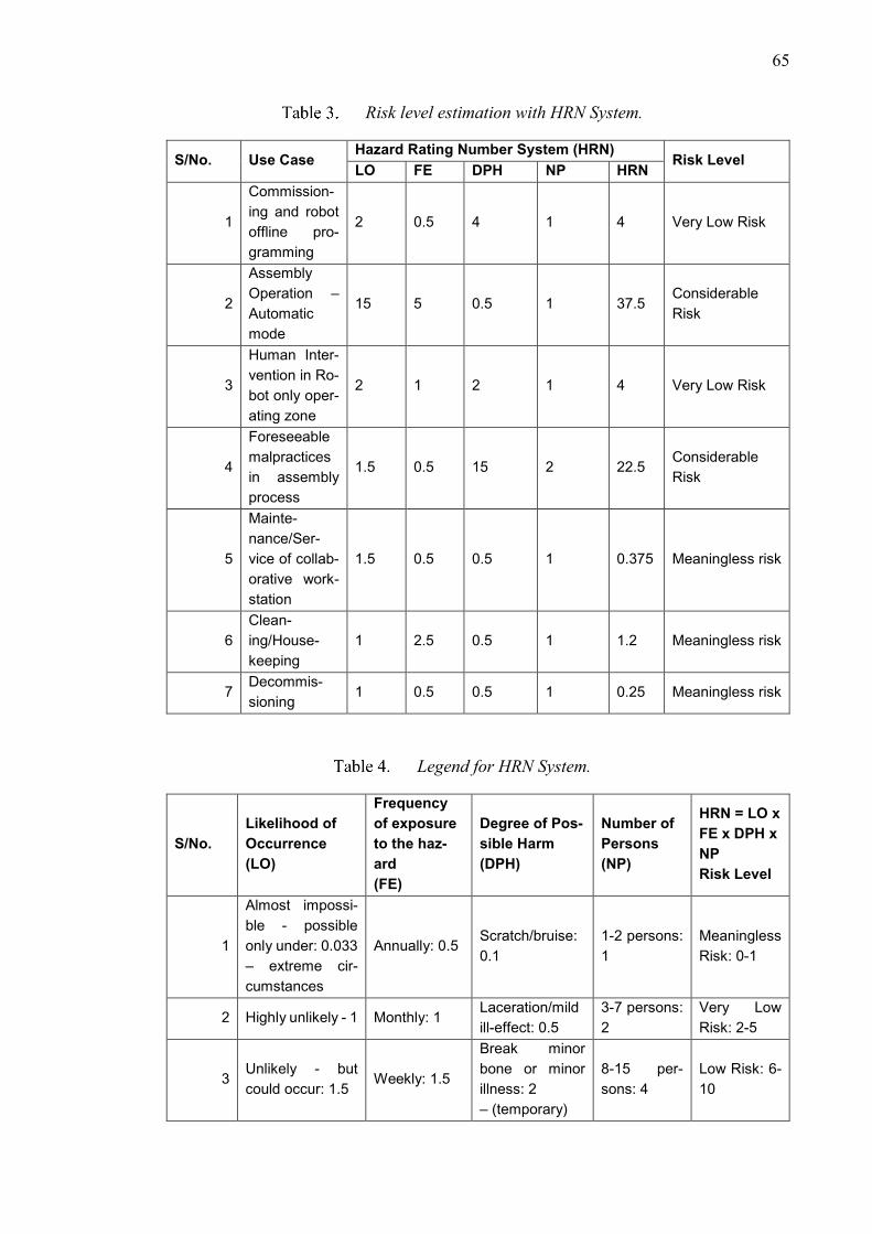
65
Risk level estimation with HRN System.
S/No. Use Case Hazard Rating Number System (HRN)
Risk Level LO FE DPH NP HRN
1
Commission-
ing and robot
offline pro-
gramming
2 0.5 4 1 4 Very Low Risk
2
Assembly
Operation –
Automatic
mode
15 5 0.5 1 37.5 Considerable
Risk
3
Human Inter-
vention in Ro-
bot only oper-
ating zone
2 1 2 1 4 Very Low Risk
4
Foreseeable
malpractices
in assembly
process
1.5 0.5 15 2 22.5 Considerable
Risk
5
Mainte-
nance/Ser-
vice of collab-
orative work-
station
1.5 0.5 0.5 1 0.375 Meaningless risk
6
Clean-
ing/House-
keeping
1 2.5 0.5 1 1.2 Meaningless risk
7 Decommis-
sioning 1 0.5 0.5 1 0.25 Meaningless risk
Legend for HRN System.
S/No.
Likelihood of
Occurrence
(LO)
Frequency
of exposure
to the haz-
ard
(FE)
Degree of Pos-
sible Harm
(DPH)
Number of
Persons
(NP)
HRN = LO x
FE x DPH x
NP
Risk Level
1
Almost impossi-
ble - possible
only under: 0.033
– extreme cir-
cumstances
Annually: 0.5 Scratch/bruise:
0.1
1-2 persons:
1
Meaningless
Risk: 0-1
2 Highly unlikely - 1 Monthly: 1 Laceration/mild
ill-effect: 0.5
3-7 persons:
2
Very Low
Risk: 2-5
3 Unlikely - but
could occur: 1.5 Weekly: 1.5
Break minor
bone or minor
illness: 2
– (temporary)
8-15 per-
sons: 4
Low Risk: 6-
10
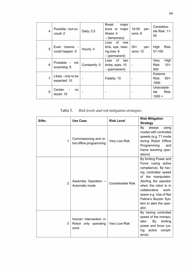
66
4 Possible - but un-
usual: 2 Daily: 2.5
Break major
bone or major
illness: 4
– (temporary)
16-50 per-
sons: 8
Considera-
ble Risk: 11-
50
5 Even chance -
could happen: 5 Hourly: 4
Loss of one
limb, eye, hear-
ing loss: 6
– (permanent)
50+ per-
sons: 12
High Risk:
51-100
6 Probable - not
surprising: 8 Constantly: 5
Loss of two
limbs, eyes: 10
– (permanent)
-
Very High
Risk: 101-
500
7 Likely - only to be
expected: 10 - Fatality: 15 -
Extreme
Risk: 501-
1000
8 Certain - no
doubt: 15 - - -
Unaccepta-
ble Risk:
1000 +
Risk levels and risk mitigation strategies.
S/No. Use Case Risk Level Risk Mitigation
Strategy
1 Commissioning and ro-
bot offline programming Very Low Risk
By always using
modes with controlled
speeds (e.g. T1 mode
during Robot Offline
Programming and
frame teaching oper-
ations)
2 Assembly Operation –
Automatic mode Considerable Risk
By limiting Power and
Force (using active
compliance). By hav-
ing controlled speed
of the manipulator.
Alerting the operator
when the robot is in
collaborative work-
space e.g. Use of flex
Fellow’s Buzzer Sys-
tem to alert the oper-
ator.
3
Human Intervention in
Robot only operating
zone
Very Low Risk
By having controlled
speed of the manipu-
lator. By limiting
power and force (us-
ing active compli-
ance).
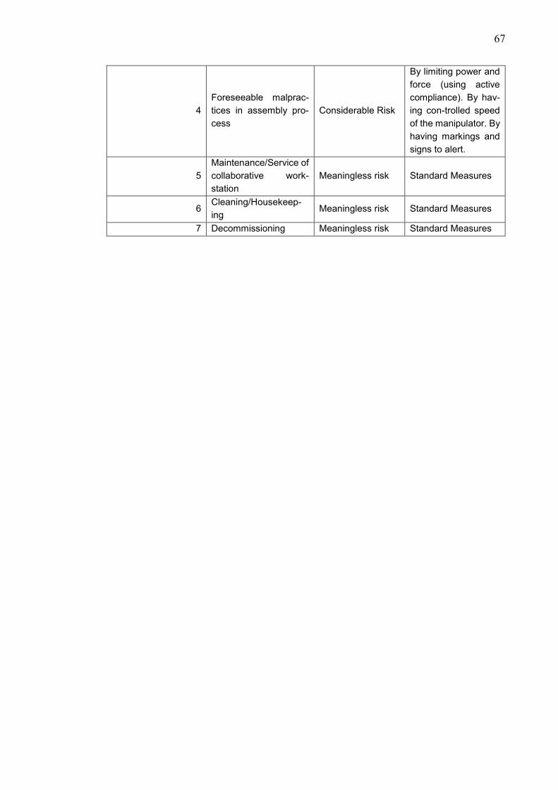
67
4
Foreseeable malprac-
tices in assembly pro-
cess
Considerable Risk
By limiting power and
force (using active
compliance). By hav-
ing con-trolled speed
of the manipulator. By
having markings and
signs to alert.
5
Maintenance/Service of
collaborative work-
station
Meaningless risk Standard Measures
6 Cleaning/Housekeep-
ing Meaningless risk Standard Measures
7 Decommissioning Meaningless risk Standard Measures

68
APPENDIX B: DFA ANALYSIS WORKSHEETS
Theoretical minimum part count
S/No. Component Assembly Stage
Phase
Theoretical Minimum
Part Count
1 DIN rail 1 1
2 Terminal Block: ZDU 2.5/4AN (Grey) 2 1
3 Terminal Block: ZDU 2.5/4AN (Grey) 2 1
4 Terminal Block: ZDU 2.5/4AN BL 2 1
5 Terminal Block: ZDU 2.5/4AN BL 2 1
6 Terminal Block: ZPE 2.5/4AN (GREEN) 2 1
7 Terminal Block: ZPE 2.5/4AN (GREEN) 2 1
8 Terminal Block: ZDU 2.5/4AN (Grey) 2 1
9 Terminal Block: ZDU 2.5/4AN (Grey) 2 1
10 Terminal Block: ZDU 2.5/4AN BL 2 1
11 Terminal Block: ZDU 2.5/4AN BL 2 1
12 Terminal Block: ZPE 2.5/4AN (GREEN) 2 1
13 Terminal Block: ZPE 2.5/4AN (GREEN) 2 1
14 ABB FH202 A 2 1
15 CHINT C6 2 1
16 CHINT D6 2 1
17 ABB D2 2 1
18 Wire Set: KM51062820G10135 3 1
19 Wire Set: KM796121G12106 3 1
20 Wire Set: KM51042524G14 3 1
21 CHINT B6 4 1
22 CHINT B10 4 1
23 ABB E251-230 4 1
24 ABB Socket 4 1
25 ABB E216 4 1
26 Labels 4 0
Total Sum 25

69
Manual assembly code assignments
S/No. Component Assembly
Stage Phase
α β α+β Manual assem-
bly code – 2 digit
1 DIN rail 1 180 360 540 11
2 Terminal Block: ZDU 2.5/4AN
(Grey) 2 360 360 720 11
3 Terminal Block: ZDU 2.5/4AN
(Grey) 2 360 360 720 11
4 Terminal Block: ZDU 2.5/4AN BL 2 360 360 720 11
5 Terminal Block: ZDU 2.5/4AN BL 2 360 360 720 11
6 Terminal Block: ZPE 2.5/4AN
(GREEN) 2 360 360 720 11
7 Terminal Block: ZPE 2.5/4AN
(GREEN) 2 360 360 720 11
8 Terminal Block: ZDU 2.5/4AN
(Grey) 2 360 360 720 11
9 Terminal Block: ZDU 2.5/4AN
(Grey) 2 360 360 720 11
10 Terminal Block: ZDU 2.5/4AN BL 2 360 360 720 11
11 Terminal Block: ZDU 2.5/4AN BL 2 360 360 720 11
12 Terminal Block: ZPE 2.5/4AN
(GREEN) 2 360 360 720 11
13 Terminal Block: ZPE 2.5/4AN
(GREEN) 2 360 360 720 11
14 ABB FH202 A 2 360 360 720 11
15 CHINT C6 2 360 360 720 11
16 CHINT D6 2 360 360 720 11
17 ABB D2 2 360 360 720 11
18 Wire Set: KM51062820G10135 3 360 0 360 10
19 Wire Set: KM796121G12106 3 360 0 360 10
20 Wire Set: KM51042524G14 3 360 0 360 00
21 CHINT B6 4 360 360 720 11
22 CHINT B10 4 360 360 720 11
23 ABB E251-230 4 360 360 720 11
24 ABB Socket 4 360 360 720 11
25 ABB E216 4 360 360 720 11
26 Labels 4 360 360 720 11

70
Individual timings for 1st test
S/No. Component Phase Time (s) Manual Assembly
codes
1 DIN rail 1 5 11
2 Terminal Block: ZDU 2.5/4AN
(Grey)
2 5 11
3 Terminal Block: ZDU 2.5/4AN
(Grey)
2 5 11
4 Terminal Block: ZDU 2.5/4AN BL 2 5 11
5 Terminal Block: ZDU 2.5/4AN BL 2 5 11
6 Terminal Block: ZPE 2.5/4AN
(GREEN)
2 5 11
7 Terminal Block: ZPE 2.5/4AN
(GREEN)
2 5 11
8 Terminal Block: ZDU 2.5/4AN
(Grey)
2 5 11
9 Terminal Block: ZDU 2.5/4AN
(Grey)
2 5 11
10 Terminal Block: ZDU 2.5/4AN BL 2 5 11
11 Terminal Block: ZDU 2.5/4AN BL 2 5 11
12 Terminal Block: ZPE 2.5/4AN
(GREEN)
2 5 11
13 Terminal Block: ZPE 2.5/4AN
(GREEN)
2 5 11
14 ABB FH202 A 2 20.3 N/A
15 CHINT C6 2 20.5 N/A
16 CHINT D6 2 20 N/A
17 ABB D2 2 21 N/A
18 Wire Set: KM51062820G10135 3 15 10
19 Wire Set: KM796121G12106 3 15 10
20 Wire Set: KM51042524G14 3 15 00
21 CHINT B6 4 20.4 N/A
22 CHINT B10 4 20.2 N/A
23 ABB E251-230 4 20.3 N/A
24 ABB Socket 4 20.2 N/A
25 ABB E216 4 20.1 N/A
26 Labels 4 60 11
Individual timings for 2nd test
S/No. Component Phase Time (s) Manual Assembly
codes
1 DIN rail 1 5 11
2 Terminal Block: ZDU 2.5/4AN
(Grey)
2 5 11
3 Terminal Block: ZDU 2.5/4AN
(Grey)
2 5 11
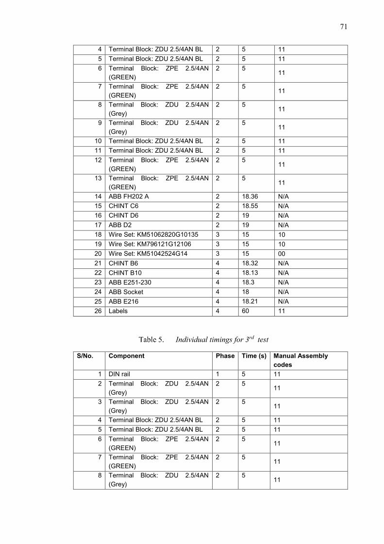
71
4 Terminal Block: ZDU 2.5/4AN BL 2 5 11
5 Terminal Block: ZDU 2.5/4AN BL 2 5 11
6 Terminal Block: ZPE 2.5/4AN
(GREEN)
2 5 11
7 Terminal Block: ZPE 2.5/4AN
(GREEN)
2 5 11
8 Terminal Block: ZDU 2.5/4AN
(Grey)
2 5 11
9 Terminal Block: ZDU 2.5/4AN
(Grey)
2 5 11
10 Terminal Block: ZDU 2.5/4AN BL 2 5 11
11 Terminal Block: ZDU 2.5/4AN BL 2 5 11
12 Terminal Block: ZPE 2.5/4AN
(GREEN)
2 5 11
13 Terminal Block: ZPE 2.5/4AN
(GREEN)
2 5 11
14 ABB FH202 A 2 18.36 N/A
15 CHINT C6 2 18.55 N/A
16 CHINT D6 2 19 N/A
17 ABB D2 2 19 N/A
18 Wire Set: KM51062820G10135 3 15 10
19 Wire Set: KM796121G12106 3 15 10
20 Wire Set: KM51042524G14 3 15 00
21 CHINT B6 4 18.32 N/A
22 CHINT B10 4 18.13 N/A
23 ABB E251-230 4 18.3 N/A
24 ABB Socket 4 18 N/A
25 ABB E216 4 18.21 N/A
26 Labels 4 60 11
Individual timings for 3rd test
S/No. Component Phase Time (s) Manual Assembly
codes
1 DIN rail 1 5 11
2 Terminal Block: ZDU 2.5/4AN
(Grey)
2 5 11
3 Terminal Block: ZDU 2.5/4AN
(Grey)
2 5 11
4 Terminal Block: ZDU 2.5/4AN BL 2 5 11
5 Terminal Block: ZDU 2.5/4AN BL 2 5 11
6 Terminal Block: ZPE 2.5/4AN
(GREEN)
2 5 11
7 Terminal Block: ZPE 2.5/4AN
(GREEN)
2 5 11
8 Terminal Block: ZDU 2.5/4AN
(Grey)
2 5 11
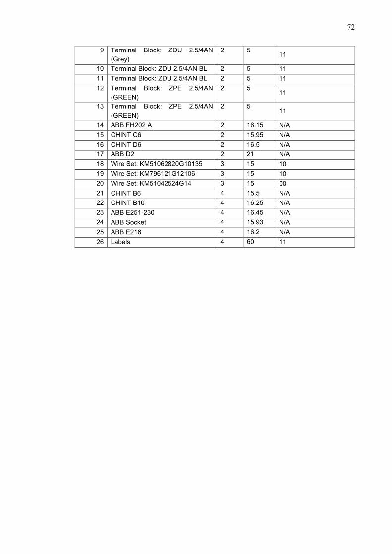
72
9 Terminal Block: ZDU 2.5/4AN
(Grey)
2 5 11
10 Terminal Block: ZDU 2.5/4AN BL 2 5 11
11 Terminal Block: ZDU 2.5/4AN BL 2 5 11
12 Terminal Block: ZPE 2.5/4AN
(GREEN)
2 5 11
13 Terminal Block: ZPE 2.5/4AN
(GREEN)
2 5 11
14 ABB FH202 A 2 16.15 N/A
15 CHINT C6 2 15.95 N/A
16 CHINT D6 2 16.5 N/A
17 ABB D2 2 21 N/A
18 Wire Set: KM51062820G10135 3 15 10
19 Wire Set: KM796121G12106 3 15 10
20 Wire Set: KM51042524G14 3 15 00
21 CHINT B6 4 15.5 N/A
22 CHINT B10 4 16.25 N/A
23 ABB E251-230 4 16.45 N/A
24 ABB Socket 4 15.93 N/A
25 ABB E216 4 16.2 N/A
26 Labels 4 60 11