Embed Size (px)
Citation preview
Draft NUREG-0700 Rev. 3
Manuscript Completed: Date Published: Prepared by: Division of Risk Analysis Office of Nuclear Regulatory Research U.S. Nuclear Regulatory Commission Washington, DC 20555-0001
Human-System Interface Design Review Guidelines

ii

iii
ABSTRACT
The U.S. Nuclear Regulatory Commission (NRC) staff reviews the human factors engineering (HFE) aspects of nuclear power plants in accordance with the Standard Review Plan (NUREG-0800, Standard Review Plan for the Review of Safety Analysis Reports for Nuclear Power Plants: LWR Edition). The Human Factors Engineering Program Review Model (NUREG-0711, Revision 3, issued November 2012) contains detailed design review procedures. As part of the review process, the interfaces between plant personnel and the plant’s systems and components are evaluated for conformance with HFE guidelines. This document, Human-System Interface Design Review Guidelines (NUREG-0700, Revision 3), provides the guidelines to perform this evaluation. The review guidelines address the physical and functional characteristics of human-system interfaces (HSIs). Because these guidelines only address the HFE aspects of design and not other related considerations, such as instrumentation and control and structural design, they are referred to as HFE guidelines. In addition to the review of actual HSIs, the NRC staff can use the NUREG-0700 guidelines to evaluate a design-specific HFE guidelines document or style guide. The HFE guidelines are organized into four basic parts, which are divided into sections. Part I contains guidelines for the basic HSI elements: information displays, user-interface interaction and management, and analog displays and controls. These elements are used as building blocks to develop HSI systems to serve specific functions. Part II contains the guidelines for reviewing the following HSI systems: alarm system, safety parameter display system, group-view display system, soft control system, computer-based procedure system, automation system, and communication system. Part III provides guidelines for the review of workstations and workplaces. Part IV provides guidelines for the review of HSI support (i.e., maintainability of digital systems and degraded HSI and instrumentation and control conditions).

iv

v
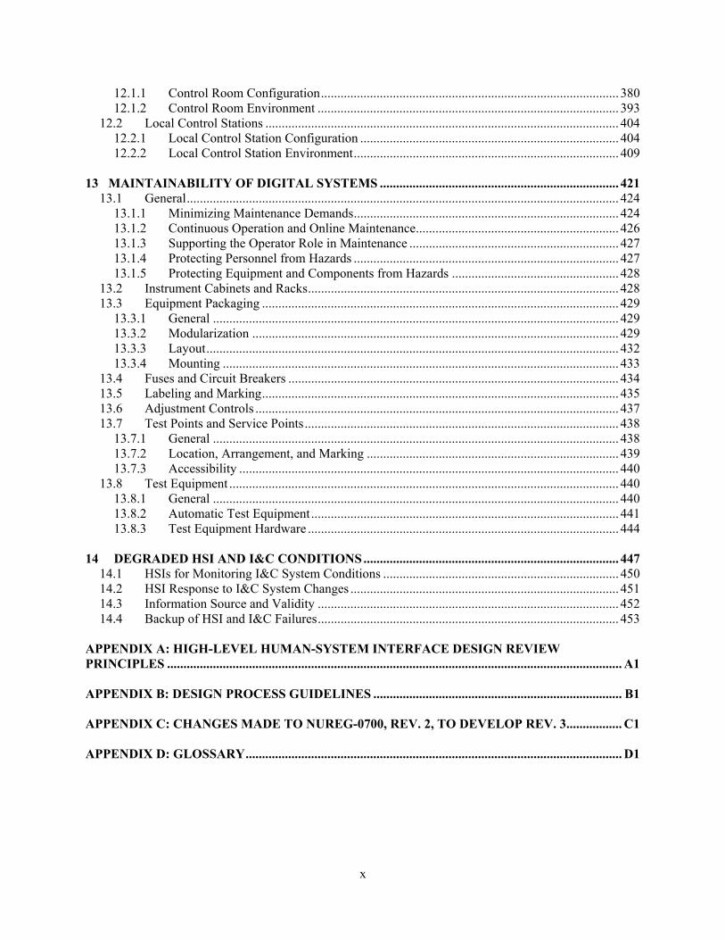
CONTENTS ABSTRACT ................................................................................................................................................. iii FIGURES ..................................................................................................................................................... xi TABLES .................................................................................................................................................... xiii PREFACE ................................................................................................................................................... xv ACRONYMS ........................................................................................................................................... xxiii 1 INFORMATION DISPLAY ................................................................................................................. 1
1.1 General Display Guidelines ............................................................................................................ 6 1.2 Display Formats ........................................................................................................................... 14
1.2.1 Continuous Text Displays ..................................................................................................... 14 1.2.2 Tables and Lists ..................................................................................................................... 16 1.2.3 Data Forms and Fields .......................................................................................................... 19 1.2.4 Bar Charts and Histograms ................................................................................................... 22 1.2.5 Graphs ................................................................................................................................... 24 1.2.6 Pie Charts .............................................................................................................................. 29 1.2.7 Flowcharts ............................................................................................................................. 29 1.2.8 Mimics and Diagrams ........................................................................................................... 30 1.2.9 Maps ...................................................................................................................................... 31 1.2.10 Integral and Configural Formats ............................................................................................ 33 1.2.11 Graphic Instrument Panels ..................................................................................................... 34 1.2.12 Speech Displays ..................................................................................................................... 35
1.3 Display Elements .......................................................................................................................... 36 1.3.1 Alphanumeric Characters ...................................................................................................... 36 1.3.2 Abbreviations and Acronyms ................................................................................................ 38 1.3.3 Labels .................................................................................................................................... 39 1.3.4 Icons and Symbols ................................................................................................................ 40 1.3.5 Numeric Data ........................................................................................................................ 41 1.3.6 Scales, Axes, and Grids ......................................................................................................... 42 1.3.7 Borders, Lines, and Arrows ................................................................................................... 46 1.3.8 Color ...................................................................................................................................... 46 1.3.9 Size, Shape, and Pattern Coding ........................................................................................... 50 1.3.10 Highlighting by Brightness and Flashing .............................................................................. 51 1.3.11 Auditory Coding .................................................................................................................... 53
1.4 Data Update Rate .......................................................................................................................... 55 1.5 Display Pages ............................................................................................................................... 56
2 USER-INTERFACE INTERACTION AND MANAGEMENT ...................................................... 61
2.1 General User Input Guidelines ..................................................................................................... 73 2.2 User Input Formats ....................................................................................................................... 85
2.2.1 Command Language ............................................................................................................. 85 2.2.2 Menus .................................................................................................................................... 88 2.2.3 Function Keys ....................................................................................................................... 98 2.2.4 Macros/Programmable Function Keys ................................................................................ 100 2.2.5 Forms .................................................................................................................................. 101 2.2.6 Direct Manipulation ............................................................................................................ 103 2.2.7 Natural Language ................................................................................................................ 107 2.2.8 Query Language .................................................................................................................. 107 2.2.9 Question and Answer .......................................................................................................... 108 2.2.10 Speech .............................................................................................................................. 109
vi
2.3 Cursors ........................................................................................................................................ 111 2.3.1 Appearance .......................................................................................................................... 111 2.3.2 Controls ............................................................................................................................... 112 2.3.3 Movement ........................................................................................................................... 113 2.3.4 Multiple Cursors .................................................................................................................. 114 2.3.5 Pointing Cursors .................................................................................................................. 115 2.3.6 Text Entry Cursors .............................................................................................................. 116 2.3.7 Multiple Display Devices .................................................................................................... 116
2.4 System Response ........................................................................................................................ 117 2.4.1 Prompts ............................................................................................................................... 117 2.4.2 Feedback ............................................................................................................................. 118 2.4.3 System Response Time ....................................................................................................... 118
2.5 Managing Displays ..................................................................................................................... 120 2.5.1 Display Selection and Navigation ....................................................................................... 120 2.5.2 Windows ............................................................................................................................. 127 2.5.3 Display Control ................................................................................................................... 134 2.5.4 Display Update or Freeze .................................................................................................... 134 2.5.5 Display Suppression ............................................................................................................ 135 2.5.6 Scrolling and Paging ........................................................................................................... 136 2.5.7 Automated Actions .............................................................................................................. 138
2.6 Managing Information ................................................................................................................ 138 2.6.1 Editing Documents .............................................................................................................. 138 2.6.2 Saving Files ......................................................................................................................... 143 2.6.3 Temporary Editing Buffer ................................................................................................... 144 2.6.4 Excerpt File ......................................................................................................................... 144
2.7 User Assistance .......................................................................................................................... 145 2.7.1 General ................................................................................................................................ 145 2.7.2 Advisory Messages ............................................................................................................. 146 2.7.3 Error Messages .................................................................................................................... 146 2.7.4 Validating User Input .......................................................................................................... 148 2.7.5 Confirming Entries .............................................................................................................. 149 2.7.6 Protecting Data .................................................................................................................... 150 2.7.7 Correcting Information or Command Entries ..................................................................... 152 2.7.8 User Guidance or Help ........................................................................................................ 153
2.8 Interface Flexibility .................................................................................................................... 155 2.9 System Security .......................................................................................................................... 157
2.9.1 User Identification ............................................................................................................... 157 2.9.2 Information Access ............................................................................................................. 159
3 ANALOG DISPLAY AND CONTROL DEVICES ........................................................................ 161
3.1 Analog Controls ......................................................................................................................... 163 3.1.1 General Control Guidelines ................................................................................................. 163 3.1.2 Pushbuttons ......................................................................................................................... 167 3.1.3 Slide Switches ..................................................................................................................... 169 3.1.4 Toggle Switches .................................................................................................................. 170 3.1.5 Rocker Switches .................................................................................................................. 171 3.1.6 Rotary Controls ................................................................................................................... 172 3.1.7 Manual Valves .................................................................................................................... 178
3.2 Analog Display Devices ............................................................................................................. 178 3.2.1 Meters .................................................................................................................................. 178 3.2.2 Light Indicators ................................................................................................................... 180

vii
3.2.3 Numeric Readouts ............................................................................................................... 181 3.2.4 Valve Position Indication .................................................................................................... 182
4 ALARM SYSTEM ............................................................................................................................. 183
4.1 Alarm Definition and Treatment ................................................................................................... 193 4.1.1 Alarm Definition .................................................................................................................... 193 4.1.2 Alarm Processing ................................................................................................................... 194 4.1.3 Alarm Prioritization and Message Availability ...................................................................... 196 4.1.4 Alarm Routing ........................................................................................................................ 197 4.1.5 Alarm Recording .................................................................................................................... 197
4.2 Information Display ....................................................................................................................... 198 4.2.1 General Alarm Display Guidelines ........................................................................................ 198 4.2.2 Display of High-Priority Alarms ............................................................................................ 199 4.2.3 Display of Alarm Status ......................................................................................................... 199 4.2.4 Display of Shared Alarms ...................................................................................................... 200 4.2.5 Alarm Contents ...................................................................................................................... 201 4.2.6 Coding Methods ..................................................................................................................... 203 4.2.7 Spatially Dedicated, Continuously Visible Alarm Displays .................................................. 208 4.2.8 Alarm Message Lists .............................................................................................................. 209 4.2.9 Alarms Integrated into Other Displays ................................................................................... 210
4.3 User-System Interaction and Controls ........................................................................................... 211 4.3.1 General Alarm Control Guidelines ......................................................................................... 211 4.3.2 Silence Functions ................................................................................................................... 212 4.3.3 Acknowledge Controls ........................................................................................................... 212 4.3.4 Reset Functions ...................................................................................................................... 212 4.3.5 Alarm Management ................................................................................................................ 213 4.3.6 Automatic Features ................................................................................................................ 214 4.3.7 Control Devices ...................................................................................................................... 214
4.4 Reliability, Test, Maintenance, and Failure Indication Features ................................................... 215 4.4.1 Reliability ............................................................................................................................... 215 4.4.2 Test ......................................................................................................................................... 216 4.4.3 Maintenance ........................................................................................................................... 216
4.5 Alarm Response Procedures .......................................................................................................... 217 4.6 Control-Display Integration and Layout ........................................................................................ 218 4.7 Integration with Other HSI Elements ............................................................................................ 219
5 SAFETY PARAMETER DISPLAY SYSTEM ............................................................................... 221
5.1 Information Display ....................................................................................................................... 225 5.2 Reliability, Test, Maintenance, and Failure Indication Features ................................................... 229 5.3 Integration with Other HSI Elements ............................................................................................ 230
6 GROUP-VIEW DISPLAY SYSTEM ............................................................................................... 231
6.1 Functional Characteristics .......................................................................................................... 233 6.1.1 General ................................................................................................................................ 233 6.1.2 Overview Display ................................................................................................................ 234 6.1.3 Access to Additional Information ....................................................................................... 237 6.1.4 Support for Crew Coordination ........................................................................................... 238 6.1.5 Crew Communication and Collaboration ............................................................................ 239
6.2 User-System Interaction ............................................................................................................. 241
viii
7 SOFT CONTROL SYSTEM............................................................................................................. 245 7.1 General ....................................................................................................................................... 253 7.2 Information Display.................................................................................................................... 254
7.2.1 General ................................................................................................................................ 254 7.2.2 Selection Displays ............................................................................................................... 255 7.2.3 Input Fields .......................................................................................................................... 255 7.2.4 Input Formats ...................................................................................................................... 256 7.2.5 Display Devices .................................................................................................................. 258
7.3 User-System Interaction ............................................................................................................. 258 7.3.1 General ................................................................................................................................ 258 7.3.2 Sequential Actions .............................................................................................................. 260 7.3.3 Verification and Confirmation Steps ................................................................................... 262 7.3.4 Interlocks, Lockouts, and Lockins ...................................................................................... 262 7.3.5 Error Detection and Correction ........................................................................................... 263 7.3.6 Selecting Plant Variables or Components ........................................................................... 264 7.3.7 Control Inputs ...................................................................................................................... 265 7.3.8 Handling Stored Data .......................................................................................................... 265 7.3.9 System Response ................................................................................................................. 266
8 COMPUTER-BASED PROCEDURE SYSTEM ............................................................................ 267
8.1 Information Display.................................................................................................................... 273 8.1.1 Procedure Identification ...................................................................................................... 273 8.1.2 Basic Steps .......................................................................................................................... 273 8.1.3 Warnings, Cautions, Notes, and Reference Materials ......................................................... 274 8.1.4 Lists ..................................................................................................................................... 275 8.1.5 Organization of Procedures ................................................................................................. 275 8.1.6 Formatting and Screen Layout ............................................................................................ 276
8.2 Functional Capabilities ............................................................................................................... 276 8.2.1 Procedure Supervision and Control ..................................................................................... 276 8.2.2 Procedure Monitoring and Assessment ............................................................................... 277 8.2.3 Monitoring of User Actions ................................................................................................ 279 8.2.4 Planning and Implementation .............................................................................................. 279
8.3 User-System Interaction ............................................................................................................. 279 8.3.1 Path Monitoring .................................................................................................................. 279 8.3.2 Navigation ........................................................................................................................... 280 8.3.3 Help ..................................................................................................................................... 280
8.4 CBP Hardware ............................................................................................................................ 280 8.5 Backup for CBPs ........................................................................................................................ 280 8.6 CBP Integration with Other HSI Elements ................................................................................. 281
9 AUTOMATION SYSTEM ................................................................................................................ 283
9.1 Automation Displays .................................................................................................................. 287 9.2 Alerts, Notifications, and Status Indications .............................................................................. 289 9.3 Interaction and Control ............................................................................................................... 290 9.4 Automation Modes ..................................................................................................................... 291 9.5 Automation Levels ..................................................................................................................... 292
9.5.1 Shared Control .................................................................................................................... 292 9.5.2 Operation by Consent .......................................................................................................... 292 9.5.3 Operation by Exception ....................................................................................................... 293
9.6 Adaptive Automation ................................................................................................................. 293 9.7 Computerized Operator Support Systems .................................................................................. 294
ix
9.8 HSI Integration .......................................................................................................................... 295 10 COMMUNICATION SYSTEM ..................................................................................................... 297
10.1 General Communication Guidelines ....................................................................................... 300 10.2 Speech-Based Communication ............................................................................................... 300
10.2.1 General Requirements ..................................................................................................... 300 10.2.2 Conventional Telephone Systems ................................................................................... 302 10.2.3 Sound-Powered Telephone Systems ............................................................................... 303 10.2.4 Portable Radio Transceivers ............................................................................................ 304 10.2.5 Announcing Systems ....................................................................................................... 305 10.2.6 Other Communications Systems ..................................................................................... 306 10.2.7 Emergency Communications ........................................................................................... 306
10.3 Computer-Based Communication ........................................................................................... 306 10.3.1 General ............................................................................................................................ 306 10.3.2 Preparing Messages ......................................................................................................... 307 10.3.3 Sending Messages............................................................................................................ 308 10.3.4 Receiving Messages ........................................................................................................ 310
11 WORKSTATION DESIGN ............................................................................................................ 313
11.1 General Workstation Guidelines ............................................................................................. 318 11.1.1 Configuration and Posture Support ................................................................................. 318 11.1.2 User Safety ...................................................................................................................... 319
11.2 Workstations Containing Primarily Analog HSIs ................................................................... 322 11.2.1 Analog Workstation Configuration ................................................................................. 322 11.2.2 Panel Layout .................................................................................................................... 325 11.2.3 Control-Display Integration ............................................................................................. 329
11.3 Workstations Containing Primarily Computer-Based HSIs ................................................... 334 11.3.1 Visual Display Devices ................................................................................................... 334 11.3.2 Computer Input Devices .................................................................................................. 342 11.3.3 Hand-Held Devices ............................................................................................................... 355 11.3.4 Desktops and Work Surfaces ........................................................................................... 356 11.3.5 Workstation Support Devices .......................................................................................... 358
11.4 Workstation Labeling and Demarcations ................................................................................ 360 11.4.1 Labels ............................................................................................................................. 360 11.4.2 Demarcations .................................................................................................................. 365
11.5 Chairs and Footrests ................................................................................................................ 366 11.5.1 General Seating Guidance ............................................................................................... 366 11.5.2 Seat Pan ........................................................................................................................... 367 11.5.3 Backrest ........................................................................................................................... 367 11.5.4 Chair Surfaces ................................................................................................................. 368 11.5.5 Armrests .......................................................................................................................... 369 11.5.6 Chair Headrest ................................................................................................................. 369 11.5.7 Chair Pedestal/Legs ......................................................................................................... 369 11.5.8 Casters ............................................................................................................................. 370 11.5.9 Temporary Seating .......................................................................................................... 370 11.5.10 Footrests ......................................................................................................................... 370 11.5.11 Clearance Behind Seated Workstations .......................................................................... 371
11.6 Printers, Recorders, and Plotters ............................................................................................. 371 12 WORKPLACE DESIGN ................................................................................................................. 375
12.1 Control Rooms ........................................................................................................................ 380
x
12.1.1 Control Room Configuration ........................................................................................... 380 12.1.2 Control Room Environment ............................................................................................ 393
12.2 Local Control Stations ............................................................................................................ 404 12.2.1 Local Control Station Configuration ............................................................................... 404 12.2.2 Local Control Station Environment ................................................................................. 409
13 MAINTAINABILITY OF DIGITAL SYSTEMS ......................................................................... 421
13.1 General .................................................................................................................................... 424 13.1.1 Minimizing Maintenance Demands ................................................................................. 424 13.1.2 Continuous Operation and Online Maintenance .............................................................. 426 13.1.3 Supporting the Operator Role in Maintenance ................................................................ 427 13.1.4 Protecting Personnel from Hazards ................................................................................. 427 13.1.5 Protecting Equipment and Components from Hazards ................................................... 428
13.2 Instrument Cabinets and Racks ............................................................................................... 428 13.3 Equipment Packaging ............................................................................................................. 429
13.3.1 General ............................................................................................................................ 429 13.3.2 Modularization ................................................................................................................ 429 13.3.3 Layout .............................................................................................................................. 432 13.3.4 Mounting ......................................................................................................................... 433
13.4 Fuses and Circuit Breakers ..................................................................................................... 434 13.5 Labeling and Marking ............................................................................................................. 435 13.6 Adjustment Controls ............................................................................................................... 437 13.7 Test Points and Service Points ................................................................................................ 438
13.7.1 General ............................................................................................................................ 438 13.7.2 Location, Arrangement, and Marking ............................................................................. 439 13.7.3 Accessibility .................................................................................................................... 440
13.8 Test Equipment ....................................................................................................................... 440 13.8.1 General ............................................................................................................................ 440 13.8.2 Automatic Test Equipment .............................................................................................. 441 13.8.3 Test Equipment Hardware ............................................................................................... 444
14 DEGRADED HSI AND I&C CONDITIONS .............................................................................. 447
14.1 HSIs for Monitoring I&C System Conditions ........................................................................ 450 14.2 HSI Response to I&C System Changes .................................................................................. 451 14.3 Information Source and Validity ............................................................................................ 452 14.4 Backup of HSI and I&C Failures ............................................................................................ 453
APPENDIX A: HIGH-LEVEL HUMAN-SYSTEM INTERFACE DESIGN REVIEW PRINCIPLES ........................................................................................................................................... A1 APPENDIX B: DESIGN PROCESS GUIDELINES ............................................................................ B1 APPENDIX C: CHANGES MADE TO NUREG-0700, REV. 2, TO DEVELOP REV. 3................. C1 APPENDIX D: GLOSSARY ................................................................................................................... D1
xi
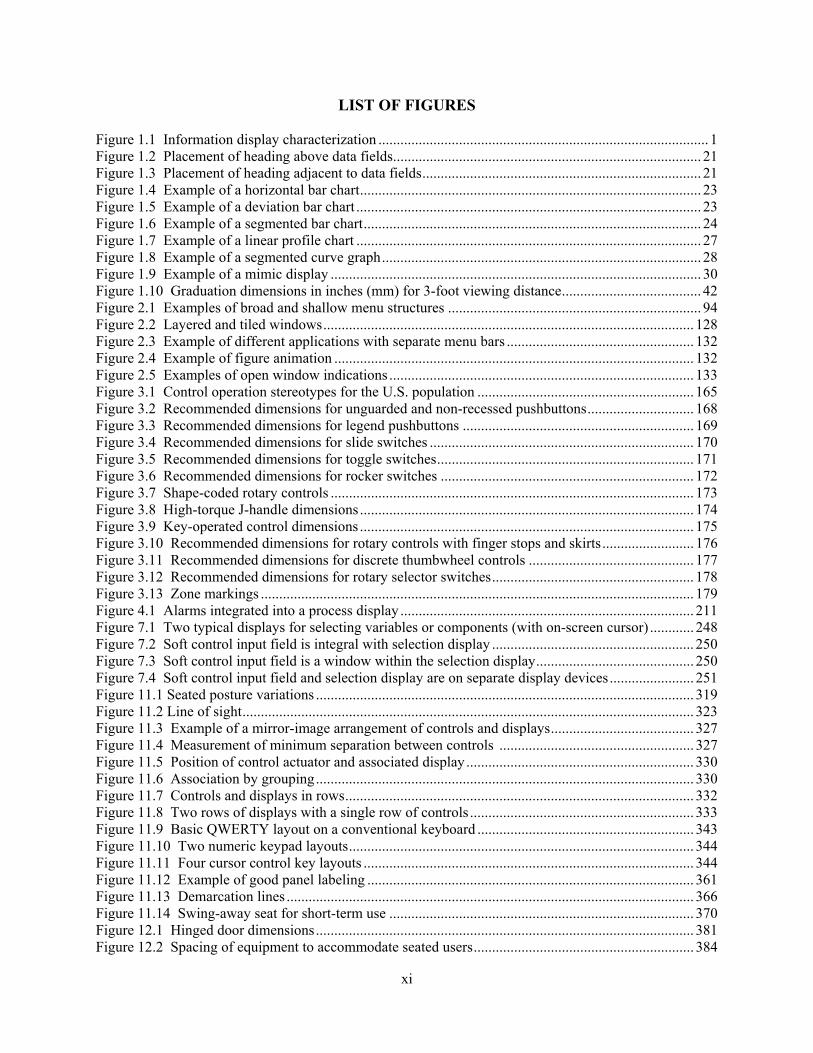
LIST OF FIGURES Figure 1.1 Information display characterization .......................................................................................... 1 Figure 1.2 Placement of heading above data fields .................................................................................... 21 Figure 1.3 Placement of heading adjacent to data fields ............................................................................ 21 Figure 1.4 Example of a horizontal bar chart ............................................................................................. 23 Figure 1.5 Example of a deviation bar chart .............................................................................................. 23 Figure 1.6 Example of a segmented bar chart ............................................................................................ 24 Figure 1.7 Example of a linear profile chart .............................................................................................. 27 Figure 1.8 Example of a segmented curve graph ....................................................................................... 28 Figure 1.9 Example of a mimic display ..................................................................................................... 30 Figure 1.10 Graduation dimensions in inches (mm) for 3-foot viewing distance ...................................... 42 Figure 2.1 Examples of broad and shallow menu structures ..................................................................... 94 Figure 2.2 Layered and tiled windows ..................................................................................................... 128 Figure 2.3 Example of different applications with separate menu bars ................................................... 132 Figure 2.4 Example of figure animation .................................................................................................. 132 Figure 2.5 Examples of open window indications ................................................................................... 133 Figure 3.1 Control operation stereotypes for the U.S. population ........................................................... 165 Figure 3.2 Recommended dimensions for unguarded and non-recessed pushbuttons ............................. 168 Figure 3.3 Recommended dimensions for legend pushbuttons ............................................................... 169 Figure 3.4 Recommended dimensions for slide switches ........................................................................ 170 Figure 3.5 Recommended dimensions for toggle switches ...................................................................... 171 Figure 3.6 Recommended dimensions for rocker switches ..................................................................... 172 Figure 3.7 Shape-coded rotary controls ................................................................................................... 173 Figure 3.8 High-torque J-handle dimensions ........................................................................................... 174 Figure 3.9 Key-operated control dimensions ........................................................................................... 175 Figure 3.10 Recommended dimensions for rotary controls with finger stops and skirts ......................... 176 Figure 3.11 Recommended dimensions for discrete thumbwheel controls ............................................. 177 Figure 3.12 Recommended dimensions for rotary selector switches ....................................................... 178 Figure 3.13 Zone markings ...................................................................................................................... 179 Figure 4.1 Alarms integrated into a process display ................................................................................ 211 Figure 7.1 Two typical displays for selecting variables or components (with on-screen cursor) ............ 248 Figure 7.2 Soft control input field is integral with selection display ....................................................... 250 Figure 7.3 Soft control input field is a window within the selection display ........................................... 250 Figure 7.4 Soft control input field and selection display are on separate display devices ....................... 251 Figure 11.1 Seated posture variations ....................................................................................................... 319 Figure 11.2 Line of sight ........................................................................................................................... 323 Figure 11.3 Example of a mirror-image arrangement of controls and displays ....................................... 327 Figure 11.4 Measurement of minimum separation between controls ..................................................... 327 Figure 11.5 Position of control actuator and associated display .............................................................. 330 Figure 11.6 Association by grouping ....................................................................................................... 330 Figure 11.7 Controls and displays in rows ............................................................................................... 332 Figure 11.8 Two rows of displays with a single row of controls ............................................................. 333 Figure 11.9 Basic QWERTY layout on a conventional keyboard ........................................................... 343 Figure 11.10 Two numeric keypad layouts .............................................................................................. 344 Figure 11.11 Four cursor control key layouts .......................................................................................... 344 Figure 11.12 Example of good panel labeling ......................................................................................... 361 Figure 11.13 Demarcation lines ............................................................................................................... 366 Figure 11.14 Swing-away seat for short-term use ................................................................................... 370 Figure 12.1 Hinged door dimensions ....................................................................................................... 381 Figure 12.2 Spacing of equipment to accommodate seated users ............................................................ 384

xii
Figure 12.3 Equipment-to-equipment distances: single person and more-than-one-person spaces ......... 385 Figure 12.4 Minimum ventilation requirements ...................................................................................... 395 Figure 12.5 Oral communication level as a function of distance and ambient noise level ...................... 402 Figure 12.6 Acceptable reverberation times ............................................................................................ 404 Figure 12.7 Permissible noise exposure limits for use of hearing protectors .......................................... 415 Figure 14.1 Characterization of the I&C system, the HSI, and human performance .............................. 448
xiii
LIST OF TABLES
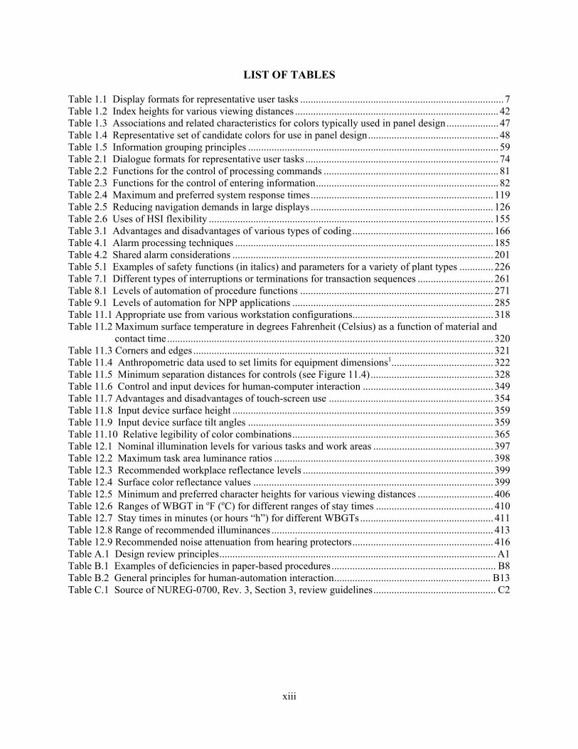
Table 1.1 Display formats for representative user tasks .............................................................................. 7 Table 1.2 Index heights for various viewing distances .............................................................................. 42 Table 1.3 Associations and related characteristics for colors typically used in panel design .................... 47 Table 1.4 Representative set of candidate colors for use in panel design .................................................. 48 Table 1.5 Information grouping principles ................................................................................................ 59 Table 2.1 Dialogue formats for representative user tasks .......................................................................... 74 Table 2.2 Functions for the control of processing commands ................................................................... 81 Table 2.3 Functions for the control of entering information ...................................................................... 82 Table 2.4 Maximum and preferred system response times ...................................................................... 119 Table 2.5 Reducing navigation demands in large displays ...................................................................... 126 Table 2.6 Uses of HSI flexibility ............................................................................................................. 155 Table 3.1 Advantages and disadvantages of various types of coding ...................................................... 166 Table 4.1 Alarm processing techniques ................................................................................................... 185 Table 4.2 Shared alarm considerations .................................................................................................... 201 Table 5.1 Examples of safety functions (in italics) and parameters for a variety of plant types ............. 226 Table 7.1 Different types of interruptions or terminations for transaction sequences ............................. 261 Table 8.1 Levels of automation of procedure functions .......................................................................... 271 Table 9.1 Levels of automation for NPP applications ............................................................................. 285 Table 11.1 Appropriate use from various workstation configurations...................................................... 318 Table 11.2 Maximum surface temperature in degrees Fahrenheit (Celsius) as a function of material and
contact time ............................................................................................................................. 320 Table 11.3 Corners and edges ................................................................................................................... 321 Table 11.4 Anthropometric data used to set limits for equipment dimensions1 ....................................... 322 Table 11.5 Minimum separation distances for controls (see Figure 11.4) ............................................... 328 Table 11.6 Control and input devices for human-computer interaction .................................................. 349 Table 11.7 Advantages and disadvantages of touch-screen use ............................................................... 354 Table 11.8 Input device surface height .................................................................................................... 359 Table 11.9 Input device surface tilt angles .............................................................................................. 359 Table 11.10 Relative legibility of color combinations ............................................................................. 365 Table 12.1 Nominal illumination levels for various tasks and work areas .............................................. 397 Table 12.2 Maximum task area luminance ratios .................................................................................... 398 Table 12.3 Recommended workplace reflectance levels ......................................................................... 399 Table 12.4 Surface color reflectance values ............................................................................................ 399 Table 12.5 Minimum and preferred character heights for various viewing distances ............................. 406 Table 12.6 Ranges of WBGT in oF (oC) for different ranges of stay times ............................................. 410 Table 12.7 Stay times in minutes (or hours “h”) for different WBGTs ................................................... 411 Table 12.8 Range of recommended illuminances ..................................................................................... 413 Table 12.9 Recommended noise attenuation from hearing protectors ...................................................... 416 Table A.1 Design review principles .......................................................................................................... A1 Table B.1 Examples of deficiencies in paper-based procedures ............................................................... B8 Table B.2 General principles for human-automation interaction ............................................................ B13 Table C.1 Source of NUREG-0700, Rev. 3, Section 3, review guidelines ............................................... C2

xiv

xv
ACKNOWLEDGMENTS
We acknowledge the valuable insights from U.S. Nuclear Regulatory Commission (NRC) and non-NRC users who have provided many comments and suggestions for improving NUREG-0700. These insights included the identification of areas where guidance is needed, as well as the technical content of individual review guidelines. We give special thanks to the Human Factors Engineering staff of the NRC’s Office of New Reactors, who provided detailed reviews of the many technical documents we prepared while developing NUREG-0700, Revision 3. We relied on many technical sources in developing new guidance and updating old guidance. Several of the documents we used were developed by consensus standards organizations, and we thank them for giving us permission to use portions of their documents. They were the Human Factors and Ergonomics Society (HFES) and the International Organization for Standardization (ISO). In updating of the workstation and workplace sections, we relied on the information contained in Human Factors Engineering of Computer Workstations (ANSI/HFES 100-2007). The material is reprinted with permission and remains copyrighted by HFES with all rights reserved. In updating the workstation and workplace sections, we also relied on the following ISO standards: • Ergonomic Design of Control Centres—Part 3: Control Room Layout (ISO 11064-3:1999)
• Ergonomic Design of Control Centres—Part 4: Layout and Dimensions of Workstations
(ISO 11064-4:2004)
• Ergonomic Design of Control Centres—Part 6: Environmental Requirements for Control Centres (ISO 11064-6:2005)
• Ergonomics of Human-System Interaction—Part 303: Requirements for Electronic Visual
Displays (ISO 9241-303:2011) This material is used with permission of the American National Standards Institute (ANSI) on behalf of ISO with all rights reserved. We also used documents developed by government organizations and would like to acknowledge them: • U.S. Department of Defense (DOD), DoD Design Criteria Standard: Human Engineering
(MIL-STD-1472G), published in 2012
• Federal Aviation Administration, Human Factors Design Standard (HF-STD-001), published in 2003
• National Aeronautics and Space Administration (NASA), NASA Space Flight Human-System Standard Volume 2: Human Factors, Habitability, and Environmental Health (NASA 3001, Vol. 2), published in 2011
Each of the guidelines identifies the documents on which it relied for the information it contains.

xvi

xvii
PREFACE Introduction The U.S. Nuclear Regulatory Commission staff reviews the human factors engineering (HFE) aspects of nuclear power plants in accordance with the Standard Review Plan (NUREG-0800, Standard Review Plan for the Review of Safety Analysis Reports for Nuclear Power Plants: LWR Edition). The Human Factors Engineering Program Review Model (NUREG-0711, Revision 3, issued November 2012) contains detailed design review procedures. The plant’s human-system interfaces (HSIs) are evaluated as part of the review process. The HSIs are the parts of a nuclear power plant with which personnel interact in performing their functions and tasks. Major HSIs include alarms, information displays, and controls. The next section describes other types of HSIs. Each type of HSI is made up of hardware and software components and is characterized in terms of its important physical and functional characteristics. The review guidelines in this document address these physical and functional characteristics of HSIs. Because these guidelines only address the HFE aspects of design rather than other related considerations, such as instrumentation and control and structural design, they are referred to as HFE guidelines. Personnel use of HSIs is influenced directly by (1) the organization of HSIs into workstations (including consoles and panels), (2) the arrangement of workstations and supporting equipment into facilities, such as a main control room, remote shutdown station, local control station, technical support center, and emergency operations facility, and (3) the environmental conditions in which the HSIs are used, including temperature, humidity, ventilation, illumination, and noise. This document provides HFE guidelines for the review of these design considerations, as well. As per the review procedures described in NUREG-0711, the guidelines in this document can be used to review the design of HSIs, as well as to review a design-specific HFE guidelines document or style guide. This section describes the overall organization of NUREG-0700 and the individual sections of review guidelines. Document Organization NUREG-0700 contains 14 sections of review guidelines and three appendices, described below. Review Guidelines Sections The HFE guidelines are organized into four basic parts, which are divided into sections. Part I contains guidelines for the basic HSI elements: information display, user-interface interaction and management, and controls. These elements are used as building blocks to develop HSI systems to serve specific functions. The guidelines address the following aspects of these HSI elements: • Information Display—This section provides HFE guidelines for reviewing visual displays.
Following a section of general guidelines, specific guidelines appear in top-down fashion, beginning with display formats (such as mimic displays and trend graphs), display format elements (such as labels, icons, symbols, color, text, and coding), data quality, and update rate.
• User-Interface Interaction and Management—This section provides HFE guidelines for reviewing
the modes of interaction between plant personnel and the HSI. Topics include dialogue formats (such as menus, direct manipulation, and command language), navigation, display controls,

xviii
entering information, system messages, and prompts. This section also contains guidelines concerning methods for verifying the integrity of data accessed through the user interface. Guidelines cover prevention of inadvertent change or deletion of data; minimization of data loss due to computer failure; and protection of data, such as setpoints, from unauthorized access.
• Analog Display and Control Devices—This section provides review guidelines for conventional
display control devices, such as meters, pushbuttons, and various types of rotary controls. Part II contains the guidelines for reviewing seven systems: alarm system, safety parameter display system, group-view display system, soft control system, computer-based procedure system, automation system, and communication system. The guidelines include the functional aspects of the system, as well as any unique considerations for display, user-system interaction, and control that may be needed to review the system. The guidelines address the following aspects of these HSI systems: • Alarm System—This section provides HFE guidelines for reviewing alarm system design
implementation. The guidelines address the selection of alarm conditions, choice of setpoints, alarm processing, alarm availability (such as filtering and suppression of alarms), unique aspects of the display of alarm information (such as organization, coding, and alarm message content), and alarm controls.
• Safety Parameter Display System—This section provides HFE guidelines for reviewing displays
of critical safety functions and safety parameters.
• Group-View Display System—This section provides HFE guidelines for reviewing group-view displays, including their functional characteristics and user-system interaction aspects, as well as their physical characteristics.
• Soft Control System—This section provides HFE guidelines for reviewing the information
display and user-system interaction aspects of soft control systems.
• Computer-Based Procedure System—This section provides HFE guidelines for reviewing computer-based procedure systems, including the representation of information, functional capabilities, users’ interaction with the systems, backup provisions, and the integration of such systems with other HSI elements.
• Automation System—This section provides HFE guidelines for reviewing human interactions
with automatic systems, including aids provided to personnel for situation analysis and decision making.
• Communication System—This section provides HFE guidelines for reviewing speech and
computer-mediated communication among plant personnel (e.g., preparing, addressing, transmitting, and receiving messages).
Part III provides guidelines for reviewing workstations and workplaces. Workstations, including consoles and panels, are locations where HSIs are integrated to provide an area where plant personnel can perform their tasks. Workstations are located in workplaces, such as the main control room and remote shutdown facilities. The guidelines address the following:

xix
• Workstation Design—This section provides HFE guidelines for reviewing the design of workstation features such as control-display integration and layout, labeling, and ergonomics (e.g., vision and reach).
• Workplace Design—This section provides HFE guidelines for reviewing general workplace
considerations, both for the control room and for operator interface areas out in the plant. The guidelines address design features such as the overall layout of the workstations and other equipment, including group-view displays within the workplace; provision of support equipment, such as ladders or tools; and environmental characteristics, including temperature, ventilation, illumination, and noise.
Part IV provides guidelines for reviewing HSI support. It contains the following two subsections: • Maintainability of Digital Systems—This section provides HFE guidelines for reviewing the
maintainability aspects of digital systems.
• Degraded HSI and Instrumentation and Control (I&C) Conditions—This section provides guidance for reviewing HSI and I&C degradations and failures on HSI resources such as alarms, displays, support systems, and controls.
Appendices This document contains four appendices. • Appendix A provides high-level HSI design review principles. These principles represent generic
HSI characteristics necessary to support personnel performance. While these principles are not detailed review guidelines, they serve several purposes. First, they were used to develop many of the detailed review guidelines in this document (see source documents). Second, as general principles, they can be used to support the evaluation of HSI aspects not well defined by the detailed guidelines. Thus, for example, they can be used in reviewing novel HSI designs, such as display formats not identified in the guidelines. Third, they can support the evaluation of the significance of individual discrepancies in the guideline.
• Appendix B contains some additional guidance for selected HSI topics that address important
considerations in the design of those topics. The purpose of these guidelines is to provide additional information for reviewers about selected topics. The guidelines in the main sections of this document address the physical and functional characteristics of HSIs and not the unique design process considerations that may be important. The guidelines were based on a technical basis described in the source documents. However, in the development of the guidelines, aspects of the design of HSIs were found to be important to human performance, but there was not a sufficient technical basis to develop detailed guidelines. Until the technical basis improves to the point where detailed guidelines can be developed, these issues can be addressed on a case-by-case basis during specific reviews. To support the latter, special guidelines address these design process considerations. Appendix B contains the guidelines for information displays, user interface interaction and management, computer-based procedure systems, automation systems, and degraded HSI and I&C conditions.
• Appendix C describes the changes between NUREG-0700, Revision 2, and Revision 3.
• Appendix D is the glossary.
xx
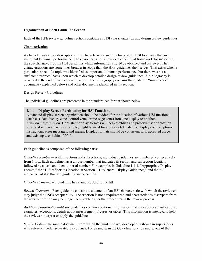
Organization of Each Guideline Section Each of the HFE review guideline sections contains an HSI characterization and design review guidelines. Characterization A characterization is a description of the characteristics and functions of the HSI topic area that are important to human performance. The characterizations provide a conceptual framework for indicating the specific aspects of the HSI design for which information should be obtained and reviewed. The characterizations are sometimes broader in scope than the HFE guidelines themselves. This exists when a particular aspect of a topic was identified as important to human performance, but there was not a sufficient technical basis upon which to develop detailed design review guidelines. A bibliography is provided at the end of each characterization. The bibliography contains the guideline “source code” documents (explained below) and other documents identified in the section. Design Review Guidelines The individual guidelines are presented in the standardized format shown below.
Each guideline is composed of the following parts: Guideline Number—Within sections and subsections, individual guidelines are numbered consecutively from 1 to n. Each guideline has a unique number that indicates its section and subsection location, followed by a dash and then its serial number. For example, in Guideline 1.1-1, “Appropriate Display Format,” the “1.1” reflects its location in Section 1.1, “General Display Guidelines,” and the “-1” indicates that it is the first guideline in the section. Guideline Title—Each guideline has a unique, descriptive title. Review Criterion—Each guideline contains a statement of an HSI characteristic with which the reviewer may judge the HSI’s acceptability. The criterion is not a requirement, and characteristics discrepant from the review criterion may be judged acceptable as per the procedures in the review process. Additional Information—Many guidelines contain additional information that may address clarifications, examples, exceptions, details about measurement, figures, or tables. This information is intended to help the reviewer interpret or apply the guideline. Source Code—The source document from which the guideline was developed is shown in superscripts with reference codes separated by commas. For example, in the Guideline 1.1-1 example, one of the
1.1-1 Display Screen Partitioning for HSI Functions A standard display screen organization should be evident for the location of various HSI functions (such as a data display zone, control zone, or message zone) from one display to another. Additional Information: Consistent display formats will help establish and preserve user orientation. Reserved screen areas, for example, might be used for a display title, alarms, display control options, instructions, error messages, and menus. Display formats should be consistent with accepted usage and existing user habits.5908, 0700

xxi
source codes is “5908.” Using the code, the reviewer can look up the source document in the bibliography at the end of the characterization. For this example, the source code is for the following document: 5908 O’Hara, J., Brown, W., Baker, C., Welch, D., Granda, T., and Vingelis, P. (1994). Advanced
Human-System Interface Design Review Guideline (NUREG/CR-5908, Vol. 2). Washington, DC: U.S. Nuclear Regulatory Commission.

xxii

xxiii
ACRONYMS ACR advanced control room ACS auxiliary cooling system AFW auxiliary feedwater ANSI American National Standards Institute APRM average power range monitor ARP alarm response procedure ASHREA American Society of Heating, Refrigerating and Air-Conditioning Engineers ASTM American Society for Testing and Materials ATE automatic test equipment ATHEANA A Technique for Human Event Analysis BWR boiling-water reactor C contrast CBP computer-based procedure CFR Code of Federal Regulations (U.S.) CIE Commission Internationale de l’Eclairage COSS computerized operator support system CR control room; contrast ratio CRI color rendering index CRT cathode ray tube DHR decay heat removal DOE Department of Energy (U.S.) EAV exposure action value ELV exposure limit value EMI electromagnetic interference EOF emergency operations facility EOP emergency operating procedure EPRI Electric Power Research Institute ET effective temperature FCC Federal Communications Commission (U.S.) GVD group view display H horizontal; height HA human action HAVS Hand-Arm Vibration Syndrome HED human engineering discrepancy HFE human factors engineering HTGR high-temperature gas-cooled reactor HRA human reliability analysis HSI human-system interface HVAC heating, ventilation, and air conditioning I&C instrumentation and control IEEE Institute of Electrical and Electronics Engineers IHX intermediate heat exchanger IRACS intermediate reactor auxiliary cooling system IRM intermediate range monitoring ISO International Organization for Standardization L luminance LC foot-candle LCS local control station LMR liquid metal reactor

xxiv
LOS line of sight LWR light-water reactor M modulation MFTA modulation transfer function area NASA National Aeronautics and Space Administration (U.S.) NC noise criteria NCB balanced noise criteria NEMA National Electrical Manufacturers Association NIOSH National Institute for Occupational Safety and Health (U.S.) NPP nuclear power plant NRC Nuclear Regulatory Commission (U.S.) OER Operating Experience Review OSHA Occupational Health and Safety Administration (U.S.) P&ID piping and instrumentation diagram PBP paper-based procedure PRA probabilistic risk assessment PWR pressurized-water reactor RCS reactor coolant system RG regulatory guide (NRC) RHR residual heat removal RPV reactor pressure vessel RVACS reactor vessel auxiliary cooling system SAR safety analysis report SART silence, acknowledge, reset, and test SDCV spatially dedicated, continuously visible display SIL speech interference levels SPDS safety parameter display system SPL sound pressure level STC sound transmission class TL transmission loss TMI Three Mile Island TSC technical support center UCS uniform color space UGR unified glare rating UHF ultrahigh frequency V vertical V&V verification and validation VD viewing distance VDU video display unit W width WBGT wet-bulb globe temperature
1
1 INFORMATION DISPLAY
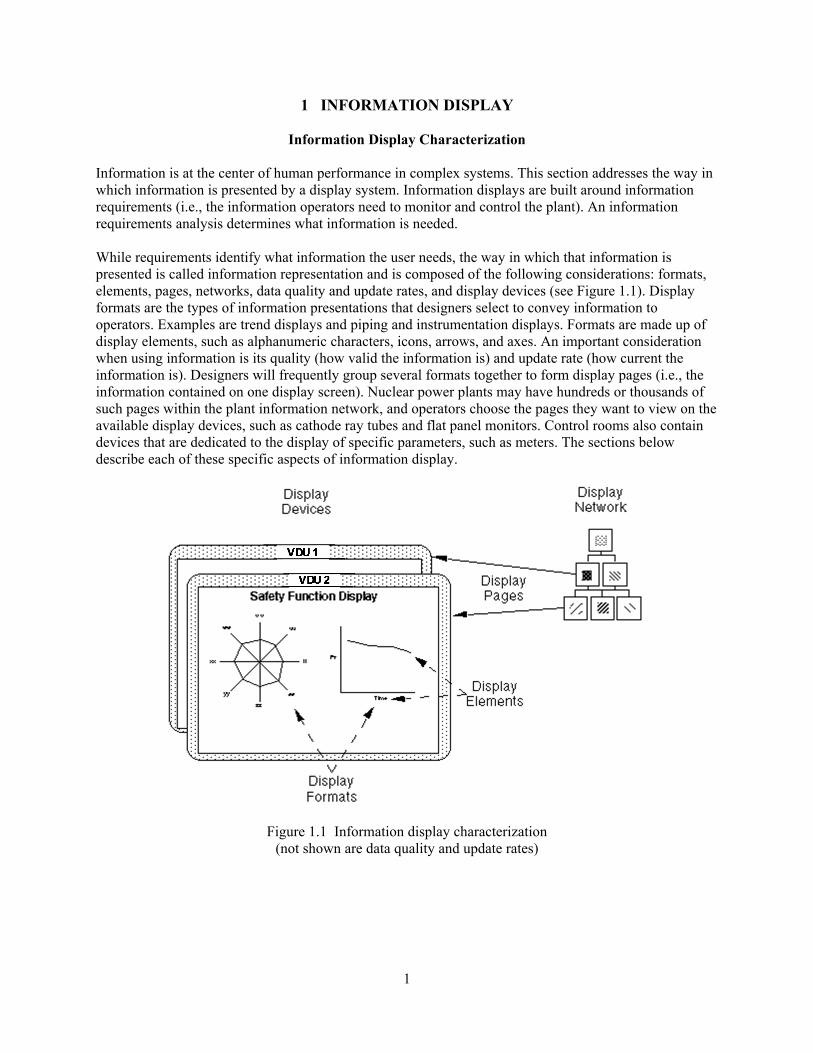
Information Display Characterization Information is at the center of human performance in complex systems. This section addresses the way in which information is presented by a display system. Information displays are built around information requirements (i.e., the information operators need to monitor and control the plant). An information requirements analysis determines what information is needed. While requirements identify what information the user needs, the way in which that information is presented is called information representation and is composed of the following considerations: formats, elements, pages, networks, data quality and update rates, and display devices (see Figure 1.1). Display formats are the types of information presentations that designers select to convey information to operators. Examples are trend displays and piping and instrumentation displays. Formats are made up of display elements, such as alphanumeric characters, icons, arrows, and axes. An important consideration when using information is its quality (how valid the information is) and update rate (how current the information is). Designers will frequently group several formats together to form display pages (i.e., the information contained on one display screen). Nuclear power plants may have hundreds or thousands of such pages within the plant information network, and operators choose the pages they want to view on the available display devices, such as cathode ray tubes and flat panel monitors. Control rooms also contain devices that are dedicated to the display of specific parameters, such as meters. The sections below describe each of these specific aspects of information display.
Figure 1.1 Information display characterization (not shown are data quality and update rates)

2
General Display Guidelines This section contains review guidance on the high-level characteristics that displays should have to support the clear and unambiguous communication of information content to users. Section 1.1 presents general display guidelines. Display Formats Display format refers to methods of information presentation consisting of an organized arrangement of smaller display elements. They are the most significant “unit of analysis” of the information system because the selection of format greatly influences the ability of operators to easily and correctly understand the information presented. Display formats range in complexity from simple, such as data fields and tables, to more complicated forms, such as configural and mimic displays. The ability of computer graphics to portray an essentially limitless set of novel graphic forms has offered great possibilities to provide operators with enhanced representations of the plant. The paragraphs below describe the formats addressed in Section 1.2. Continuous Text Displays This format consists of alphanumeric character strings (i.e., words and numbers) arranged in uninterrupted linear arrays, such as sentences and paragraphs. Examples include a text-based description of a plant system and an instructional step in a computer-based procedure display. Section 1.2.1 presents review guidelines. Tables and Lists A table is a display containing alphanumeric characters arranged by rows and columns. A list is a display containing alphanumeric strings arranged in a single column by rows. Section 1.2.2 presents review guidelines. Data Forms and Fields A data field is a space in a display containing information (e.g., the current value of a variable). Some data fields may accept input entered by the user. A data form is a display containing one or more data fields. Section 1.2.3 presents review guidelines. Bar Charts and Histograms A bar chart is a graphic figure in which numeric quantities are represented by the linear extent of parallel lines (or bars), either horizontally or vertically. A histogram is a type of bar chart used to depict the frequency distribution for a continuous variable. The variable may be grouped into classes. Section 1.2.4 presents review guidelines. Graphs A graph is a display that represents the variation of a variable in comparison with that of one or more other variables. For example, pressure may be plotted as a function of temperature. Section 1.2.5 presents review guidelines. Certain types of graphs (see “Integral and Configural Displays,” below) use emergent features to portray higher level information; Section 1.2.10 gives review guidelines for such displays.

3
Pie Charts A pie chart is a circular chart divided into sections (as pieces of a pie) to represent graphically the relative proportions of different parts of a whole. The segments may represent magnitudes or frequencies. Section 1.2.6 presents review guidelines. Flowcharts A flowchart is a diagram that illustrates sequential relations among elements or events. Flowcharts are often shown as boxes connected by arrows. Section 1.2.7 presents review guidelines. Mimics and Diagrams A mimic is a display format combining graphics and alphanumerics used to integrate system components into functionally oriented diagrams that reflect component relationships. For example, a mimic display may be used to provide a schematic representation of a system. A diagram is a special form of picture in which details are only shown if they are necessary for a task. For example, an electrical wiring diagram for a facility would show wiring but not necessarily furniture or plumbing. Section 1.2.8 presents review guidelines. Maps A map is a graphical representation of an area or a space, such as the layout of a room or a facility. Section 1.2.9 presents review guidelines. Integral and Configural Displays The quantity of data presented in the control room can, at times, overload the operator. To lower the workload associated with extracting meaningful information from data, displays may be designed to help integrate data into more meaningful units of information. These displays map low-level data, process constraints, and relevant performance goals into the appearance and dynamic behavior of a graphical element so that this information is readily available. The two types of displays, integral and configural, differ in how they represent the relationships among data. Integral displays show information in such a way that the individual parameters used to generate the display are not represented in it. For example, a display might provide information on overall system status by the appearance of an icon. The icon may change appearance based on computations involving lower level parameters, but the parameter values themselves are not presented. In configural displays, the relationships among parameters are represented as emergent features of a graphical element. (An emergent feature is a global perceptual feature that is produced by the interactions among individual lines, contours, and shapes.) In contrast to integral displays, information about the individual parameters is also available in the display. Configural displays often use simple graphic forms, such as a polygon. Information that could be presented by separate display formats is integrated into a single format in which each of the separate pieces of information is represented, for example, by the distance of a polygon’s vertex from its center. In addition, the geometric shape of the polygon provides a high-level summary (the emergent feature). Section 1.2.10 presents review guidelines for both display types.

4
Graphic Instrument Panels These are formats in which graphical objects are arranged to resemble instruments in a control panel. For example, an individual indicator may appear as a circular meter containing a numerical scale and an indicating needle. Section 1.2.11 presents review guidelines. Speech Displays These displays provide information in the form of speech (either computer generated or a recorded human voice). Messages are conveyed to the user through audio devices, such as speakers and headsets. Section 1.2.12 presents review guidelines. Display Elements Display elements are the building blocks of the display formats. Section 1.3 contains review guidance for the following display elements. Alphanumeric Characters These are symbols consisting of letters, digits, and, usually, other symbols, such as punctuation marks. Section 1.3.1 presents review guidelines. Abbreviations and Acronyms An abbreviation is a shortened form of a word or phrase used for brevity (e.g., the word “pressure” might be abbreviated as “press”). An acronym is a word formed from the initial letter of each of the successive or major parts of a compound term. For example, the acronym SART is sometimes used to represent the alarm system control operations: silence, acknowledge, reset, and test. Section 1.3.2 presents review guidelines. Labels A label is a descriptor containing one or more character strings that is intended to support users in identifying structures or components. Section 1.3.3 presents review guidelines. Icons and Symbols An icon is a pictorial, pictographic, or other nonverbal representation of objects or actions. A symbol is a representation of something by reason of relationship, association, or convention. Symbols used in information displays may be alphanumerical characters or abstract shapes. Section 1.3.4 presents review guidelines. Numeric Data These are data represented in numerical form (as opposed to text form). Examples include numeric representations of plant variables or control setpoints. Section 1.3.5 presents review guidelines. Scales, Axes, and Grids Scales, axes, and grids are used to graphically represent data. Axes are the graphic representation of orthogonal dimensions in the form of lines (e.g., the horizontal and vertical axes of a plot may be the X

5
and Y dimensions, respectively). A scale is a graduated series of demarcations indicating the divisions of an axis. A grid is a network of uniformly spaced horizontal and vertical lines for locating points by means of coordinates. Section 1.3.6 presents review guidelines. Borders, Lines, and Arrows Borders, lines, and arrows are basic elements used to present information graphically. Lines are used to connect objects or to provide a demarcation between objects. A border is a set of demarcation lines that frame an object or group of objects. Arrows are lines that indicate direction. Section 1.3.7 presents review guidelines. Color Color is an aspect of objects or light sources that may be described in terms of hue, lightness (or brightness), and saturation. Coding based on the use of color is an important means for representing information in displays. Section 1.3.8 presents review guidelines. Size, Shape, and Pattern Coding These are three methods for coding information in graphic displays. Size coding allows objects to be compared and contrasted based on relative size. Shape coding allows objects to be compared and contrasted based on similarities and differences in their outlines (shape). Pattern coding supports comparisons and contrasts of objects based on similarities in such characteristics as size, color, position, and orientation. Section 1.3.9 presents review guidelines. Highlighting by Brightness and Flashing Highlighting is a means of directing the user’s attention to a feature of the display. Highlighting that is based on brightness attempts to increase an object’s salience by making it appear brighter than other objects. Flashing increases salience by increasing and decreasing, in alteration, the brightness of an object or its background. Section 1.3.10 presents review guidelines. Auditory Coding This is a type of information coding that conveys meaning through the use of sounds, such as auditory tones. Section 1.3.11 presents review guidelines. Data Update Rate The ability of personnel to use information depends to a great degree on the frequency with which it is updated. The data update rate refers to the frequency with which data sensors are sampled and the contents of a display are refreshed. Section 1.4 presents review guidelines. Display Pages Display pages are defined sets of information intended to be presented as a single unit. Typical nuclear power plant display pages may combine several different formats on a single video display unit (VDU) screen, such as combining bar charts and digital displays within a representation of a piping and instrumentation diagram. The content of a display page (i.e., the integration of formats that make up the page) is usually intended to provide an organized view of some aspect of the process. For example, a page may provide a high-level status overview of the primary system. Display pages typically have a label and

6
designation within the computer system so they can be accessed by operators as a single “display.” Section 1.5 presents review guidelines. A comprehensive review of information displays should include how they are affected by degraded human-system interface (HSI) and instrumentation and control (I&C) conditions. Degraded conditions can have significant impacts on proper HSI functioning. Section 14 provides guidance for reviewing degraded HSI and I&C conditions. While developing the guidance for information systems, the NRC staff identified several considerations that are important to crew performance and safety but for which the technical basis was insufficient to develop specific human factors engineering guidelines. The design process considerations presented in Appendix B1 should address these aspects of information system design on a case-by-case basis. Bibliography Source Code Documents
0700 U.S. Nuclear Regulatory Commission (1981). Guidelines for Control Room Design Reviews (NUREG-0700). Washington, DC: U.S. Nuclear Regulatory Commission.
0800 U.S. Nuclear Regulatory Commission (1996). Standard Review Plan for the Review of Safety
Analysis Reports for Nuclear Power Plants: LWR Edition (NUREG-0800, Rev. 1), Washington, DC: U.S. Nuclear Regulatory Commission.
5908 O’Hara, J., Brown, W., Baker, C., Welch, D., Granda, T., and Vingelis, P. (1994). Advanced
Human-System Interface Design Review Guideline (NUREG/CR-5908, Vol. 2). Washington, DC: U.S. Nuclear Regulatory Commission.
6546 O’Hara, J., and Brown, W. (2001). Human-System Interface Management: Human Factors
Review Guidance (BNL Technical Report W6546-T6A-1-3/01). Upton, New York: Brookhaven National Laboratory.
6636 Stubler, W., Higgins, J., and Kramer, J. (2000). Maintainability of Digital Systems: Technical
Basis and Human Factors Review Guidance (NUREG/CR-6636). Washington, DC: U.S. Nuclear Regulatory Commission.
1.1 General Display Guidelines 1.1-1 Appropriate Display Format The display presentation format (e.g., table, graph, flowchart) should be consistent with tasks that the user will be performing with the displayed information (see Table 1.1). Additional Information: Table 1.1 provides some formats and conditions for their appropriate use in the context of five representative user tasks. Display formats should be task dependent. While the table identifies several classical display formats, novel formats can be acceptable if their support for the users’ tasks can be demonstrated. Because tasks can vary, advanced HSIs should provide the user with the flexibility to display information in alternative formats that reflect changes in task requirements.5908, 0700

7
Table 1.1 Display formats for representative user tasks
Representative Task Format Condition for Appropriate Use Comprehending Instructions or General Descriptions
Continuous Text General Lists Series of related items Speech Displays User’s attention not directed toward text
display Flowcharts Sequential decision process with no
tradeoffs Examining and Comparing Individual Numerical Values or Text
Tables Detailed comparisons of ordered sets of data
Data Forms Detailed comparisons of related sets of data items from separately labeled fields
Examining Functional Relationships of Components of a System
Mimics and Diagrams General
Examining Spatial Relationships of Objects or Places
Diagrams General Maps Geographical data
Examining and Interpreting Patterns in Numerical Data
Bar Charts Single variable viewed over several discrete entities or at discrete intervals
Histograms Frequency of occurrence viewed at discrete intervals of a single variable
Pie Charts Relative distribution of a single variable over several categories
Graphs Two or more continuous variables Graphs: Scatterplot Spatial distribution of data within a
coordinate system
1.1-2 Display Conventions Consistent interface design conventions should be evident for all display features (such as labels). Additional Information: Consistent structure for data and labels should be used within and across displays. Even minor inconsistencies can distract a user and delay comprehension as the user wonders momentarily whether some apparent difference represents a real difference. Both the items on display and the displays themselves should be standardized. Although standardization is desirable, it should not take precedence over the grouping principles of frequency, sequence, locations, and importance.5908 1.1-3 Display Information Consistent with User Conventions Information should be displayed consistently according to standards and conventions familiar to users. Additional Information: The wording of displayed data, labels, and other information should incorporate the task-oriented terminology of the users and should avoid unfamiliar terms used by designers and programmers.5908 1.1-4 Display Information Consistent with Control Requirements Displays should be consistent in word choice, format, and basic style with requirements for data and control entry. Additional Information: When entry formats are consistent with display formats, users are less likely to make errors.5908
8
1.1-5 Correspondence Mapping There should be an explicit mapping between the characteristics and functions of the system to be represented and the features of the display representation (i.e., changes in the appearance of the display form should have a one-to-one relation with the plant states it represents). These changes should result from explicit rules relating the physical form of the display and its meaning to the plant state represented. Additional Information: Correspondence mapping addresses how well the display communicates meaningful information about the plant to operators. The physical form and functions of the display should be explicitly tied to the plant’s functions and states. The display form and function should consider the instrumentation and the data processing that drive the display format. If a single display can lead to more than one interpretation, it is ambiguous and can be misunderstood. Changes in the graphic display should be unambiguously related to the plant’s state. The same graphic change should not be associated with more than one interpretation.6633 1.1-6 Levels of Abstraction Displays should provide information at the levels of abstraction necessary to meet the operators’ requirements relative to their task goals. Additional Information: Information should be presented in accord with the operator’s goals and the information needed to address them.6633 1.1-7 Coherence Mapping The characteristics and features of the display used to represent the process should be readily perceived and interpreted by the operator. Additional Information: Coherence mapping addresses how comprehensible the representation is to the operator. Unambiguous relationships between the display and the process are of little value if they also are not readily perceived by the operators and easily understood.6633 1.1-8 Understandability of Higher Level Information The methods by which lower level data are analyzed to produce higher level information and graphic elements should be understandable to users. Additional Information: Users should be able to judge the acceptability of higher level information and how it relates to lower level information.6633 1.1-9 User Verification of Higher Level Information Operators should have access to the rules or computations that link process parameters and graphic features and to an explanation of how the information system produces higher level information. Additional Information: When graphic features change in ways not completely understood by operators, they should be able to access the rules that produce the graphic forms. Operators should be able to review any analysis performed by the information system.6633 1.1-10 Alert to Higher Level Displays While viewing secondary (lower level) displays, the system should provide a perceptual (audible or visual) cue to alert the user to return to the primary (higher level) display if significant information in that display requires user attention.0800 1.1-11 Display of Goal Status The information system should provide for global situation awareness (i.e., an overview of the status of all the operator’s goals at all times) as well as supply details about the current specific goal. Additional Information: Situation assessment can suffer when operators focus on some information and fail to attend to other important data.6633
9
1.1-12 Display of Information to Support Planning The HSI should present information to support users in planning for and coordinating concurrent tasks. Additional Information: Providing information that gives advanced notification of plant conditions or the need for action can help users prioritize and plan tasks. It can also reduce the mental workload and improve the use of cognitive resources for primary tasks. Examples of HSI features that can provide advanced warnings and indications include checklists and computer-based aids that allow the user to look ahead at future activities (e.g., computer-based procedures that show upcoming steps), trend and predictor displays, and alarms and displays that provide early warnings of developing conditions. This information should be presented in ways that reduce distraction, because distracting stimuli can impose high demands on attention resources.6546 1.1-13 Display of Future Status The information system should support the user’s ability to project future states of the system when this is required to safely operate the plant. Additional Information: Situation assessment involves not only understanding the current state of the plant but also projecting its future state. Displays such as trend graphs can support these projections.6633 1.1-14 Status at a Glance Information display systems should allow users to immediately assess overall plant status and detect conditions that require attention without performing interface management tasks. Additional Information: The presentation area of computer-based display devices allows only a limited amount of information to be presented at one time. If personnel are unable to view information without deliberately performing interface management tasks, they may be less willing to search for particular information. They also may be less likely to encounter the information casually, as one might when scanning a conventional control panel. This effect can interfere with awareness of developing plant conditions that have not yet exceeded the threshold of the alarm system. Without this awareness, the user may not form the intention to monitor these conditions. Salient indications of anomalies are particularly important for highly reliable automated systems, which users may fail to investigate because of their low failure rate.6546 1.1-15 Actual System and Equipment Status Indications of the actual status of plant systems and equipment, as opposed to demand status, should be provided when required by the task. Additional Information: Demand information shows that equipment has been commanded (by control settings or otherwise) to a particular state or level. It shows only what is demanded, not what is actually being realized. Status information shows the state or level actually in effect. To prevent operator confusion, it is essential that displays identify whether they reflect demand or actual status.0700 1.1-16 Display of Parameters and Variables Important to Safety Plant parameters and variables important to safety should be displayed in a way that is convenient and readily accessible.0800 1.1-17 Normal Value Reference Index Displays should contain references to the values of normal operating conditions. Additional Information: With references showing normal-parameter operating values, the users are more likely to notice deviations from normal conditions. In such cases, the index might be displayed as a horizontal or vertical line, or perhaps as a reference curve of some kind. For example, a horizontal line representing normal operating conditions could be superimposed on the display.5908
10
1.1-18 Critical Value Reference Index A display should include a reference index when the user must compare displayed information with some critical value. Additional Information: Indexing may be complicated in some situations, such as when a series of bar charts do not have a common measure. In such a case, it might help to use an index scheme such that bar lengths will fall in the same zone under normal conditions, so that deviations in bar length will be readily noticed by users who must monitor changing data. For example, a horizontal line might be an adequate reference index for a vertical bar graph.5908, 0800 1.1-19 Limit Marks for Critical Variables Limit marks should be used to indicate operational limits for critical plant parameters. Additional Information: Limit marks are demarcations of established limits of operation, such as those for technical specifications, process limits, and safety system actuation setpoints.0800 1.1-20 Choice of Status Setpoints Setpoints used to indicate a change in status should be chosen to provide users with sufficient time to respond appropriately. Additional Information: Status setpoints are criterion values used to indicate a change in the status of a variable, such as to indicate the approach to an unsafe operating condition. Status setpoints should be chosen specifically for their suitability for that function. Poorly chosen setpoints can result in frequent false indications or the failure to recognize a serious condition.0800 1.1-21 Annotating Displays with Time Data When task performance requires or implies the need to assess the currency of information within a display, the information should be annotated with time information.5908 1.1-22 Freezing Rapidly Changing Information When task requirements dictate that current information changes be continuously viewed and the display is changing so rapidly that the information is difficult to read, the user should be able to simultaneously view the information in a supplemental “snapshot” display (i.e., a display frozen to enhance readability) along with the continuous display. Additional Information: For example, if a numeric data display is changing rapidly and the user finds it difficult to read, it should be possible to display a frozen, unchanging value representing the data at the point of the request. The original display should continue to be presented.5908 1.1-23 Freeze Feedback If a display has a freeze capability, it should have an obvious reminder that it is in the freeze mode. Additional Information: It is desirable to provide this information to the user in an attention-grabbing mode, such as with a flashing message.5908 1.1-24 Navigational Links to Related Information Displays should provide navigational links to and from high-level and lower levels of information and to reference and supporting information when needed for operators’ tasks.6633 1.1-25 Grouping of Related Information The display should organize related information into groups. Additional Information: Information needed by the operator to accomplish a task should be grouped and perceptually related, when possible. To minimize the disadvantages of divided attention, the number of attention shifts should be minimized, both within a display page and between pages.6546, 6633

11
1.1-26 Spatial Proximity for Related Information Information that must be compared or mentally integrated should be presented in close spatial proximity. Additional Information: If possible, the information items should be contained on the same display page and grouped together. Spatial proximity may also be achieved by presenting the display pages in adjacent display windows or on adjacent display devices that can be viewed together.6546 1.1-27 Chromatic Proximity for Related Information If information must be mentally integrated, the display should use similar color codes for the information items. Additional Information: Information items may be easier to identify if a similar color coding scheme has been applied to them. This may be particularly important if the information items are spatially separated.6546 1.1-28 Similar Physical Dimensions for Related Information Information that must be compared or mentally integrated should use similar physical dimensions to convey meaning. Additional Information: Physical dimensions are physical characteristics that are varied to convey information, such as indicating the magnitude of a variable by the length of a line versus the volume of a shape. Using the same type of physical dimension to convey meaning requires less mental effort to interpret and integrate the information.6546 1.1-29 Similar Presentation Formats for Related Information Information that must be compared or mentally integrated should be presented using similar presentation formats (e.g., analog versus digital). Additional Information: Presentation format refers to analog versus digital form. Information items may be easier to identify and mentally integrate if they are presented in the same format, such as when both are in an analog form or both are presented as digital values. Presenting information in different formats (i.e., using different perceptual coding) requires additional mental effort to translate and integrate the information.6546 1.1-30 Display Information in Directly Usable Form Information should be displayed to users in directly usable form consistent with the task requirements. Additional Information: Users should not have to convert displayed data into another form to make it useful to the ongoing task. A user should not have to transpose, compute, interpolate, or translate displayed data into other units or refer to documentation to determine the meaning of displayed data.5908, 0700 1.1-31 Indication of Transformations Needed The display should clearly indicate scale multiplication factors (i.e., powers of 10), if used.0700 1.1-32 Annotating Graphic Displays with Numeric Values When precise reading of a graphic display is required, the display should be annotated with actual data values to supplement their graphic representation. Additional Information: For example, adjacent numeric annotation might be added to the ends of displayed bars on a bar graph; numeric data might be displayed to mark the points of a plotted curve.5908 1.1-33 Readability Conditions Important display elements and codes should be identifiable and readable from the maximum viewing distance and under minimal ambient lighting conditions.
12
Additional Information: Some pictorial patterns may be effective only when the viewing distance and lighting conditions are optimum.5908 1.1-34 Sensitivity Display dynamic sensitivity should be selected to minimize the display of normal random variations in equipment performance.0700 1.1-35 Numeral and Letter Styles Numeral and letter styles should be simple and consistent. Additional Information: See Section 1.3.1, “Alphanumeric Characters,” for more guidelines regarding lettering style.0700 1.1-36 Display Flexibility Users should be able to control the amount, format, and complexity of displayed data to meet task requirements.5908 1.1-37 Range of Conditions Displayed The display system should correctly display information about the plant’s safety status, including severe accident symptoms.0800 1.1-38 Distinctive Coding of Critical Information The display should use distinctive coding or highlighting when a user’s attention must be directed to changes in the state of the system, critical or off-normal data, and hazardous conditions. Additional Information: Significant changes might include discrepant data exceeding acceptable limits or data failing to meet some other defined criteria. “Highlight” is used here in its general sense, meaning to emphasize or make prominent, and is not restricted to any particular method of display coding, such as brightening or inverse video. Highlighting is most effective when used sparingly, adding emphasis to a display that is relatively uniform in appearance except for just a few highlighted items. For some purposes, location coding (i.e., displaying important items consistently in a particular location) might be a sufficient means of highlighting, as when an error message appears in a space otherwise left blank. However, auxiliary codes may still be needed to highlight important items, even if they are positioned consistently. For example, line coding by color or bolding might be used to highlight displayed paths or the boxes or other graphic elements representing displayed states. (Color coding may be particularly appropriate in flowcharts because of the effective primacy of color for guiding the visual scanning required to trace paths.)5908 1.1-39 Salience Levels The salience of graphic features should reflect the importance of the information. Additional Information: The most salient features of a graphic display should be those aspects of the representation that are most important. Less important information should not be more perceptually salient than more important information.6633 1.1-40 Readability of Coded Information Coding should not interfere with the readability of displayed information.5908 1.1-41 Highlighting Text Displays When critical text merits emphasis to set it apart from other text, that text should be highlighted by bolding or brightening, color coding, or some auxiliary annotation.

13
Additional Information: Displays should limit the use of capitalization as a coding technique because it reduces readability. A single word might be capitalized for emphasis but capitalizing an extended passage should not be used for coding.5908 1.1-42 Graphic Display Enhancement with Text When a graphic display contains some outstanding or discrepant feature that merits attention by a user, it should include supplementary text to emphasize that feature. Additional Information: For example, a flow diagram for process control might include a current advisory message, “Possible Pressure Valve Failure,” as well as appropriate graphic indications of the problem.5908 1.1-43 Coding Display Items Requiring Rapid Discrimination Displays should use coding when a user must distinguish rapidly among different categories of displayed data. Additional Information: Graphic coding methods (e.g., symbols, boxes, underlines, use of color as a background to grouped items) can greatly aid users’ assimilation of such information.5908, 0700 1.1-44 Meaningful Codes Displays should use meaningful or familiar rather than arbitrary codes.5908 1.1-45 Consistent Coding Across Displays Codes should have consistent meanings from one display to another. Additional Information: When coding is not consistent, the user’s task of display interpretation may be made more difficult than if no auxiliary coding were used at all.5908, 0700 1.1-46 Coding and Transmission Time Coding should not increase transmission time.5908 1.1-47 Online Dictionary of Display Element Definitions The user should have access to a dictionary that contains definitions for all display element conventions through the display or an online help system. Additional Information: Definitions should be available for all symbols, icons, and coding techniques. A legend on the display may show display conventions.5908 1.1-48 Physical Overlays Overlays should not distract from or interfere with the observation or interpretation of displayed information. Additional Information: Avoid mechanical overlays on VDUs.0800 1.1-49 Hardcopy of VDU Displays Users should be able to obtain an accurate and complete hardcopy of any VDU display. Additional Information: Online displays can offer some advantages over printed graphics, in terms of animation and highlighting. When a display is to be printed, however, it is important to realistically consider the limitations of the print medium. If a printed replica of the screen does not appear satisfactory, the hardcopy should be reformatted to maintain readability and clarity.5908, 0700 1.1-50 Display Area Displays should provide a sufficient viewing area to include all important information to prevent repetitive transitions between displays.

14
Additional Information: Lack of display area is a frequent complaint. The number of VDUs in a control room often is determined before there is sufficient knowledge about what information users need for their tasks.6546 1.1-51 Predefined Displays Predefined information groupings should be available. Additional Information: Arranging displayed information may disrupt ongoing tasks or introduce new opportunities for error if the operator fails to recognize that the arrangement of displayed information has been changed. Predetermined information groupings may help reduce interface management demands.6546 1.1-52 Indicating Locations for Important Information The system should support the user in identifying displays and indicators that should be monitored during upset conditions. Additional Information: The HSI design should help users determine where to look next within the display system for changes in information that are important to their tasks.6546 1.2 Display Formats 1.2.1 Continuous Text Displays 1.2.1-1 Standard Text Format A standard text display format should be used from one display to another.5908 1.2.1-2 Consistency Between VDU-Based Text and Printed Text VDU displays of textual data, messages, or instructions should generally follow design conventions for printed text. Additional Information: Adoption of familiar design conventions for text displays will permit users to rely on prior reading skills.5908 1.2.1-3 Sentences Begin with Main Topic The main topic of each sentence should be located near the beginning of the sentence.5908 1.2.1-4 Clarity of Wording Text displays should be worded simply and clearly.5908 1.2.1-5 Distinct Wording Distinct words rather than contractions or combined forms should be used, especially in phrases involving negation. Additional Information: For example, “will not” should be used rather than “won’t.” 5908 1.2.1-6 Concise Wording The text should be worded concisely to aid comprehension. Additional Information: Wording should be concise but not cryptic. Omitting articles (“the,” “a”), prepositions (“of,” “by”) and relative pronouns (“that,” “which,” “who”) may save some space but may also reduce understandability.5908 1.2.1-7 Abbreviations Defined in Text When words in text displays are abbreviated, each abbreviation (or acronym) should be defined in parentheses following its first appearance.

15
Additional Information: Users should have an online dictionary of abbreviations for convenient reference.5908 1.2.1-8 Affirmative Sentences Affirmative statements rather than negative statements should be used. Additional Information: The user should be told what to do rather than what to avoid. For example, “Start the pump before opening the valve” is preferred over “Do not open the valve before starting the pump.”5908 1.2.1-9 Active Voice Sentences should be composed in the active rather than the passive voice. Additional Information: Sentences in the active voice will generally be easier to understand. For example, “Press RESET to clear the screen” is preferred over “The screen is cleared by pressing RESET.”5908 1.2.1-10 Temporal Sequence When a sentence describes a sequence of events, it should be phrased with a corresponding word order. Additional Information: Temporal order is preferred over reverse order, which may confuse a user. For example, “Start the pump before opening the valve” is preferred over “Before opening the valve, start the pump.”5908 1.2.1-11 Minimum Number of Displayed Lines When a user must read continuous text on a computer display, at least four lines of text should be displayed at one time. Additional Information: Four lines of text are the minimum that should be displayed when the reading material is simple in content. If the content is more complex, or if a reader will need to refer frequently to previous material, then more lines of text should be displayed.5908 1.2.1-12 Line Length Continuous text should be displayed in wide columns, containing at least 50 characters per line. Additional Information: When space for text display is limited, display a few long lines of text rather than many short lines of text. Line lengths of less than 50 characters result in slower reading times, but line lengths from 50 to 80 characters do not produce differences in reading time.5908 1.2.1-13 Minimal Hyphenation In a display of textual material, words should be kept intact, with minimal breaking by hyphenation between lines. Additional Information: Text is more readable if each word is entirely on one line.5908 1.2.1-14 Conventional Punctuation Conventional punctuation should be used in textual display. Additional Information: Sentences, for example, should end with a period.5908 1.2.1-15 Interword Spacing Consistent spacing between the words of displayed text should be maintained, with left justification of lines and ragged right margins. A minimum of one character width (capital N for proportional spacing) should be used between words. Additional Information: Reading is easier with constant spacing, which outweighs the advantage of an even right margin achieved at the cost of uneven (nonproportional) spacing. Uneven spacing is a greater problem with narrow column formats than with wide columns. Uneven spacing handicaps poor readers more than good readers. Full justification slows reading time and should only be used if it can be achieved by variable spacing, maintaining constant proportional differences in spacing between and
16
within words, and consistent spacing between words in a line.5908, 0700 1.2.1-16 Interline Spacing A minimum of two stroke widths or 15 percent of character height, whichever is greater, should be used for spacing between lines of text. Additional Information: The specified spacing is in addition to the space used for uppercase accent marks or for lower case descenders of characters.5908 1.2.1-17 Interparagraph Spacing Displayed paragraphs of text should be separated by at least one blank line.5908 1.2.1-18 Combining Text with Other Data Text should be formatted in a few wide lines rather than in narrow columns of many short lines when space is limited by the display of graphics or other data.5908 1.2.1-19 Placing Figures Near Their Citations When tables or graphics are combined with text, each figure should be placed near its first citation in the text, preferably in the same display frame. Additional Information: Users may not bother to find and look at a figure if it is displayed separately from its citation in the text. As an exception, if a figure is cited at several points in the text, then it might be desirable to allow an optional display of the figure at user request, perhaps as a temporary window overlay at each point of citation. Also, if a figure is cited at several points in printed text, and particularly if that text may be accessed at different places by its readers, then it might be desirable to group figures consistently at a particular location, such as at the end of each section.5908 1.2.1-20 Underlining for Emphasis When a line is placed under an item to mark or emphasize it, the line should not impair the legibility of the item (e.g., by obscuring the descenders).5908 1.2.1-21 Font Coding Within a text file or table, the use of a different font style should be preferred over the use of a different size for highlighting information. Additional Information: It is often not possible to introduce into displayed text differences in type size large enough to be readily discernable.5908 1.2.1-22 Attention Symbols in Alphanumeric Displays When a special symbol, such as an asterisk, is used to draw attention to a selected item in alphanumeric displays, the symbol should be separated from the beginning of the word by a space.5908 1.2.1-23 Hardcopy for Lengthy Text Displays When a user must read lengthy textual material, that text should be available in printed form. Additional Information: Reading lengthy text on an electronic display may be 20–30 percent slower than reading it from a printed copy.5908 1.2.2 Tables and Lists 1.2.2-1 Logical Organization Information should be organized in some recognizable logical order to facilitate scanning and assimilation. Additional Information: If the data in the rows have order, the order should be increasing from left to right. If the data in the columns have order, the order should be increasing from top to bottom of the
17
display. Items in lists should be arranged in a recognizable order, such as chronological, alphabetical, sequential, functional, or importance. Where no other principle applies, lists should be ordered alphabetically. It is the user’s logic that should prevail rather than the designer’s logic, where those are different.5908 1.2.2-2 Table Layout by Row and Column A table should be constructed so that row and column labels represent the information a user has before consulting the table. Additional Information: The far-left column should contain the labels for the row variables, and the top row should contain the labels for the column variables. When tables are used for reference, the reference item should be displayed in the left column, and the material most relevant for user response should be displayed in the next adjacent column.5908 1.2.2-3 Row and Column Labels Each row and column should be uniquely and informatively labeled and should be visually distinct from data entries.5908 1.2.2-4 Labeling Units of Measurement Labels should include the unit of measure for the data in the table; when cells have the same measurements, the units of measurement should be part of row or column labels.5908 1.2.2-5 Consistent Spacing within Tables Consistent column and row spacing should be maintained within a table and from one table to another. Similarly, spacing between rows should be consistent within a table and between related tables. Additional Information: As an exception, when columns are grouped under superheadings, extra space between superheadings may help to emphasize that the columns under any single superheading are related.5908 1.2.2-6 Minimum Column Spacing The spacing between columns should be greater than any internal spaces that might be displayed within a tabulated data item. Additional Information: The columns in a table should be separated by enough blank spaces, dots, or some other distinctive feature to ensure separation of entries within a row. When columns are not separated by vertical lines, the columns should be separated by at least two character widths.5908, 0700 1.2.2-7 Row Separation In dense tables with many rows, a blank line, dots, or some other distinctive feature (to aid horizontal scanning) should be inserted after a group of rows at regular intervals. Additional Information: For many applications, it will suffice to insert a blank line after every five rows.5908 1.2.2-8 Consistent Character Appearance The font and size of alphanumeric characters should be consistent within a table and between related tables. Additional Information: An exception to this guideline is when a word or set of characters is highlighted by varying the typeface; for example, with italics or a bold font.5908 1.2.2-9 Justification of Alphabetic Data Columns of alphabetic data should be displayed with left justification to permit rapid scanning.

18
Additional Information: As an exception, indentation can be used to indicate subordinate elements in hierarchic lists. In addition, a short list (of just four or five items) could be displayed horizontally on a single line, in the interest of compact display format, if done consistently.5908 1.2.2-10 Justification of Numeric Data Columns of numeric data should be justified with respect to a fixed decimal point; if there is no decimal point, then numbers should be right justified.5908 1.2.2-11 Arabic Numerals for Numbered List Items Arabic rather than Roman numerals should be used when listed items are numbered. Additional Information: Arabic numbers are more familiar to most users and require less interpretation than Roman numerals do. The advantage of Arabic numbers becomes greater when large numbers are used.5908 1.2.2-12 Numbered Items Start with “1” Item numbers should begin with one rather than zero.5908 1.2.2-13 Continuous Numbering in Multipage Lists When a list of numbered items exceeds one display page, the items should be numbered continuously in relation to the first item on the first page. Additional Information: For example, items continued on the next page should be numbered relative to the last item on the previous page.5908 1.2.2-14 Repeated Elements in Hierarchic Numbering Complete numbers should be displayed for hierarchic lists with compound numbers (i.e., repeated elements should not be omitted). Additional Information: Implicit numbering may be acceptable for tasks involving perception of list structure. Complete numbering is better, however, for tasks that require searching for and identifying individual items in the list.5908 1.2.2-15 Single-Column List Format Lists should be formatted so that each item starts on a new line. Additional Information: A list should be displayed as a single column. As an exception, listing in multiple columns may be considered where shortage of display space dictates a compact format.5908 1.2.2-16 Marking Multiline Items in a List When a single item in a list continues for more than one line, items should be marked in some way so that the continuation of an item is obvious. Additional Information: A continued portion should not appear to be a separate item. Items might be separated by a blank space, or continuing lines within an item might be indented, or each item might be numbered or marked by a special symbol such as an arrow or bullet.5908 1.2.2-17 Vertical List Extension Beyond One Page Where lists extend over more than one display page, the last line of one page should be the first line on the succeeding page.5908 1.2.2-18 Hierarchic Structure for Long Lists For a long list, extending more than one displayed page, a hierarchic structure should be used to permit its logical partitioning into related shorter lists.5908
19
1.2.2-19 Vertical Ordering in Multiple Columns If a list is displayed in multiple columns, the items should be ordered vertically within each column rather than horizontally within rows and across columns.5908 1.2.2-20 Annotating Display of Continued Data When lists or tables are of variable length and may extend beyond the limits of one display page, the user should be informed when data are continued on another page and when data are concluded on the present page. Additional Information: For example, incomplete lists might be marked “continued on next page,” “continued,” or “more.” Concluding lists might display a note such as “end of list” or “end.” As an exception, short lists where the conclusion is evident from the display format need not be annotated in this way.5908 1.2.3 Data Forms and Fields 1.2.3-1 Comparing Data Fields Data fields to be compared on a character-by-character basis should be positioned one above the other.5908 1.2.3-2 Consistent Format Across Displays The ordering and layout of corresponding data fields across displays should be consistent from one display to another. Additional Information: For example, time records might be consistently punctuated with colons, as HH:MM:SS or HH:MM; dates might be shown as MMM:DD:YYYY. The convention chosen should be familiar to the prospective users.5908, 0700 1.2.3-3 Consistency of VDU and Hardcopy Formats The format of a VDU data form should be similar to that of commonly used hardcopy source documents. Additional Information: Users should be able to transfer their previous training and experience with the hardcopy format to the computer display.5908 1.2.3-4 Form Compatible for Data Entry and Display When forms are used for data entry as well as for data display, the formats of these forms should be compatible.5908 1.2.3-5 Visually Distinct Labels and Data Entry Areas Clear visual definition of data fields should be provided so that the data are distinct from labels and other display features. Additional Information: Special characters (such as underlining) or graphics (such as “boxing”) should be used to delineate data fields. A broken underscore, for example, could be used to indicate the number of characters available for an entry.5908 1.2.3-6 Separation of Field Label and Data Entry Area At least one character space should separate the label and the data entry area.5908 1.2.3-7 Data Field Separation At least three spaces should appear between the longest data field in one column and the rightmost label in an adjacent column. Additional Information: Where space constraints exist, vertical lines may be substituted for spaces for separation of columns of fields.5908

20
1.2.3-8 Justification: Data Field Labels of Equal Length When label sizes are relatively equal, both labels and data fields should be left justified. One space should be left between the longest label and the data field column.5908 1.2.3-9 Justification: Data Field Labels of Unequal Length When label sizes vary greatly, labels should be right justified and the data fields should be left justified. One space should be left between each label and the data field.5908 1.2.3-10 Protected Labels Field labels should be protected from keyed entry by having the cursor skip over them automatically when a user is spacing or tabbing. Additional Information: When a user must change a displayed form, including changes to field labels, then that user should be able to override label protection.5908 1.2.3-11 Highlight Active Data Entry Field The current field to be entered should be highlighted. Additional Information: Irrelevant objects slow perceptual processing by competing for resources. Use of highlighting allows the current data field to be distinguished from other data.5908 1.2.3-12 Data Entry Cues If appropriate, labels should be used to help cue the user as to the expected data entry. Additional Information: For example, “DATE (MM/DD/YYYY): __/__/__.”5908 1.2.3-13 Label Punctuation as Entry Cue The label for each entry field should end with a special symbol, signifying that an entry may be made. Additional Information: A symbol should be reserved exclusively for prompting user entries.5908 1.2.3-14 Data Form Entry Error Data entered that do not match the predefined format of the data form should be highlighted and signaled to the user. Additional Information: A beep, for example, can be used to signal an error.5908 1.2.3-15 Distinguishing Blanks from Nulls Blanks (keyed spaces) should be distinguished from nulls (no entry at all) in the display of data forms, where it can aid task performance. Additional Information: Some special symbol might be adopted to denote null entry. If field delimiters are displayed to guide data entry, then it will often be sufficient simply to leave those delimiters unchanged when no entry has been made.5908 1.2.3-16 Labeling Groups of Data Fields A field group heading should be centered above the labels to which it applies.5908 1.2.3-17 Data Field Group Separation At least five spaces should appear between groups of data fields.5908 1.2.3-18 Headings and Label Indentation When headings are located on the line above related screen fields, the labels should be indented a minimum of five spaces from the start of the heading.

21
Additional Information: Scanning an inquiry screen will be aided if headings identify logical groupings of fields (see Figure 1.2). This permits scanning of headings until the correct one is located, at which point the visual search steps down one level to the items within the grouping itself. The above guideline is intended to provide easily scanned headings.5908
Figure 1.2 Placement of heading above data fields
1.2.3-19 Heading Proximity to Subordinate Labels When headings are placed adjacent to the related fields, they should be located to the left of the topmost row of related fields. The column of labels should be separated from the longest heading by a minimum of three blank spaces. Additional Information: Scanning an inquiry screen will be aided if logical groupings of fields are identified by headings (see Figure 1.3). This permits scanning of headings until the correct one is located, at which point the visual search steps down one level to the items within the grouping itself. The above guideline is intended to provide easily scanned headings.5908
Figure 1.3 Placement of heading adjacent to data fields
1.2.3-20 Logical Organization of Data Entry Forms A data entry form should have a logical organization. Additional Information: Data entry forms contain multiple fields in which the user enters information, usually by typing, to request information from the system. Logical organizations of entry fields may include conventional order (a generally accepted or customary ordering), sequence of use, frequency of use, data comparison (entries that must be compared are grouped together), functional grouping (related functions are grouped together), importance (task-critical items are located prominently), and general to specific (detailed fields proceed from more general topics, as in a hierarchic organization). Logical organizations can support user comprehension of the layout of the data entry form and facilitate its use. When it is not necessary to enter information in all fields to complete a transaction, placing the most frequently used entry fields at the top of the form can reduce the length of transitions across the data form.6546 1.2.3-21 Minimizing the Number of Pages for a Data Form The number of pages in a data form required to complete a transaction should be minimized to reduce the amount of navigation.

22
Additional Information: Movement between individual display pages delays the transaction and causes the user to divert attention from the data entry task to the form navigation task. To reduce movement between individual pages, the number of display pages required for the completion of a transaction should be minimized by integrating required data entry fields into the fewest pages.6546 1.2.3-22 Cursor Positioning The cursor should be positioned at the first character location of the first data entry field upon initial presentation of a data entry form. Additional Information: Subsequently, the cursor should be positioned at the first character location of each entry field accessed on the data form.6546 1.2.3-23 Movement Between Entry Fields The user should be able to move from one entry field to the next using a simple action that requires minimal focused attention. Additional Information: Users should not have to divert attention from the data entry task to focus on moving from one data entry field to another. For example, operating a tab key requires less attention and precise control than positioning a cursor using a pointing device.6546 1.2.4 Bar Charts and Histograms 1.2.4-1 Labeling Single Bars Each bar on the display should have a unique identification label. Additional Information: The label provides a positive identification of the parameter each bar represents. A user should not have to memorize the position of each parameter on the display.5908 1.2.4-2 Labeling Paired Bars When bars are displayed in pairs, they should be labeled as a unit, with individual distinguishing labels for each bar. Additional Information: Direct labeling of bars will make the information easier to use. If the user has to refer to a separately displayed legend, interpretation of the chart will be slower and more subject to error.5908 1.2.4-3 Bar Spacing When data must be compared, bars should be adjacent to one another and spaced such that a direct visual comparison can be made without eye movement. Additional Information: Figure 1.4 illustrates a horizontal bar chart. The spacing between bars should be less than the bar width. If many bars are displayed, then spacing may produce an alternating pattern of bright and dark bands that could prove visually disturbing. In this case, it is preferable to arrange the bars contiguously (i.e., without spaces).5908
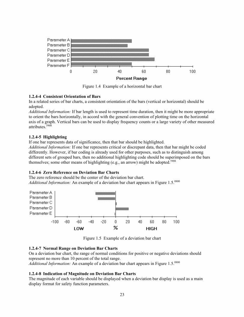
23
Figure 1.4 Example of a horizontal bar chart
1.2.4-4 Consistent Orientation of Bars In a related series of bar charts, a consistent orientation of the bars (vertical or horizontal) should be adopted. Additional Information: If bar length is used to represent time duration, then it might be more appropriate to orient the bars horizontally, in accord with the general convention of plotting time on the horizontal axis of a graph. Vertical bars can be used to display frequency counts or a large variety of other measured attributes.5908 1.2.4-5 Highlighting If one bar represents data of significance, then that bar should be highlighted. Additional Information: If one bar represents critical or discrepant data, then that bar might be coded differently. However, if bar coding is already used for other purposes, such as to distinguish among different sets of grouped bars, then no additional highlighting code should be superimposed on the bars themselves; some other means of highlighting (e.g., an arrow) might be adopted.5908 1.2.4-6 Zero Reference on Deviation Bar Charts The zero reference should be the center of the deviation bar chart. Additional Information: An example of a deviation bar chart appears in Figure 1.5.0800
Figure 1.5 Example of a deviation bar chart
1.2.4-7 Normal Range on Deviation Bar Charts On a deviation bar chart, the range of normal conditions for positive or negative deviations should represent no more than 10 percent of the total range. Additional Information: An example of a deviation bar chart appears in Figure 1.5.0800 1.2.4-8 Indication of Magnitude on Deviation Bar Charts The magnitude of each variable should be displayed when a deviation bar display is used as a main display format for safety function parameters.

24
Additional Information: The actual values of critical parameters should appear on the deviation bar display in addition to percent deviation.0800 1.2.4-9 Coding Segmented Bar Charts Segmented bars, in which differently coded segments are shown cumulatively within a bar, should be used when both the total measures and the portions represented by the segments are of interest. Additional Information: An example of a segmented bar chart appears in Figure 1.6.5908
Figure 1.6 Example of a segmented bar chart
1.2.4-10 Ordering Data in Segmented Bars The data categories should be ordered within each bar in the same sequence, with the least variable categories displayed at the bottom and the most variable at the top. Additional Information: Sometimes there are independent logical grounds for ordering data categories. If a segmented bar graph that is constructed on a logical basis produces a confusing irregularity of segments, then it might be better to display the data in some other graphic format. Any irregularity in the bottom segment will “propagate” throughout the segments above it, which will make it difficult for a user to examine irregularities in the upper segments.5908 1.2.5 Graphs 1.2.5-1 Interpreting Graphs Graphs should convey enough information to allow the user to interpret the data without referring to additional sources.5908 1.2.5-2 Labeling Curves When multiple curves are included in a single graph, each curve should be identified directly by an adjacent label rather than by a separate legend.
25
Additional Information: As an exception, where displayed curves are too close for direct labeling, an acceptable alternative might be to distinguish the various curves in some way, perhaps by color coding or line coding, and identify their codes in a separate legend. Direct labeling will permit users to assimilate information more rapidly than displaying a separate legend.5908 1.2.5-3 Legend Ordering If a legend must be displayed, the codes in the legend should be ordered to match the spatial order of their corresponding curves in the graph itself.5908 1.2.5-4 Coding To Distinguish Curves Coding should be used when multiple functions are displayed in a single graph. Additional Information: Coding should be provided particularly if curves approach or intersect one another. Coding is required to distinguish one curve from another.5908 1.2.5-5 Consistent Line Coding Line coding should be used consistently across graphs.5908 1.2.5-6 Highlighting Significant Curves In displays of multiple curves, if one curve represents data of particular significance, then that curve should be highlighted. Additional Information: If one curve represents critical or discrepant data, for example, that curve might be displayed with a noticeably thicker line stroke or in a different color. If line coding is already used to distinguish among multiple curves, then the means of highlighting any particular curve should be selected so that it will not be confused with coding for visual separation. For example, if displayed curves are distinguished by line codes (solid, dashed, or dotted), then one curve might be highlighted by displaying it in a different color.5908 1.2.5-7 Trending Time Intervals Trend displays should be capable of showing data collected during time intervals of different lengths. Additional Information: A short time base of just a few minutes is needed to study fast changing trends, while other trends may not show significant changes for several hours.5908 1.2.5-8 Multiple Trend Lines When the user must compare data represented by separate curves, the curves should be displayed in one combined graph. Additional Information: Combined plots should be related, so the user can correlate changes in one variable with changes in other key variables. Only those curves requiring comparison should be combined, because, as the number of curves on a graph increases, the user’s task of comparison will become more difficult.5908 1.2.5-9 Stability of Trend Data Trend rates should not fluctuate because of minor fluctuations in data or oscillatory behavior that may be superimposed on a well-defined trend.0800 1.2.5-10 Indication of Nonrepresentative Trend Data When a simple quantitative rate-of-change value is used, an indication should be provided to inform the user when, as a result of minor fluctuations or oscillations, the rate value does not accurately represent the trend.0800
26
1.2.5-11 Display of Projected Values Curves representing planned, projected, or extrapolated data should be distinct from curves representing actual data. Additional Information: Curves representing projected data, for example, could be depicted as broken, dashed, or dotted lines, while curves representing actual data could be represented as solid lines.5908 1.2.5-12 Curve Averaging Several individual curves should only be combined into a single average curve when users do not need to know the pattern of individual curves or when curves differ based on minor irregularities. Additional Information: Curve averaging should be performed with caution since averages tend to “wash out” local variations.5908 1.2.5-13 Repeating Display of Cyclic Data Where curves represent cyclic data, the graph should be extended to repeat uncompleted portions of the displayed cycle. Additional Information: This will allow users to scan any critical portion of the displayed cycle without having to return visually to the beginning of the plot. How much extension is desirable will depend on the particular application.5908 1.2.5-14 Target Area Definition The target area, preferred combination of X- and Y-axis values, should be graphically defined. Additional Information: Monitoring a pressure-temperature display, which presents a saturation curve that bisects the subcooled water region and the superheated steam region, is an example of a task situation where graphic depiction of a target area should be provided. This sort of display is best used for detecting deviations from normal if a target area can be defined. By plotting a brief time history, one may be able to predict where the values are headed. Care should be taken to distinguish the current value from past values, especially when the values change slowly. This can be done by placing a symbol or code for the current value.5908 1.2.5-15 Minimize Clutter Old data points should be removed after some fixed period of time. Additional Information: Ideally, as one new point is plotted, the oldest point should be removed, thereby maintaining a constant number of displayed points.5908 1.2.5-16 Linear Profile Pattern Recognition The graph should form recognizable geometric patterns for specific abnormal conditions. Additional Information: An example of a linear profile graph appears in Figure 1.7. The irregular profile is indicative of abnormal operating conditions.5908
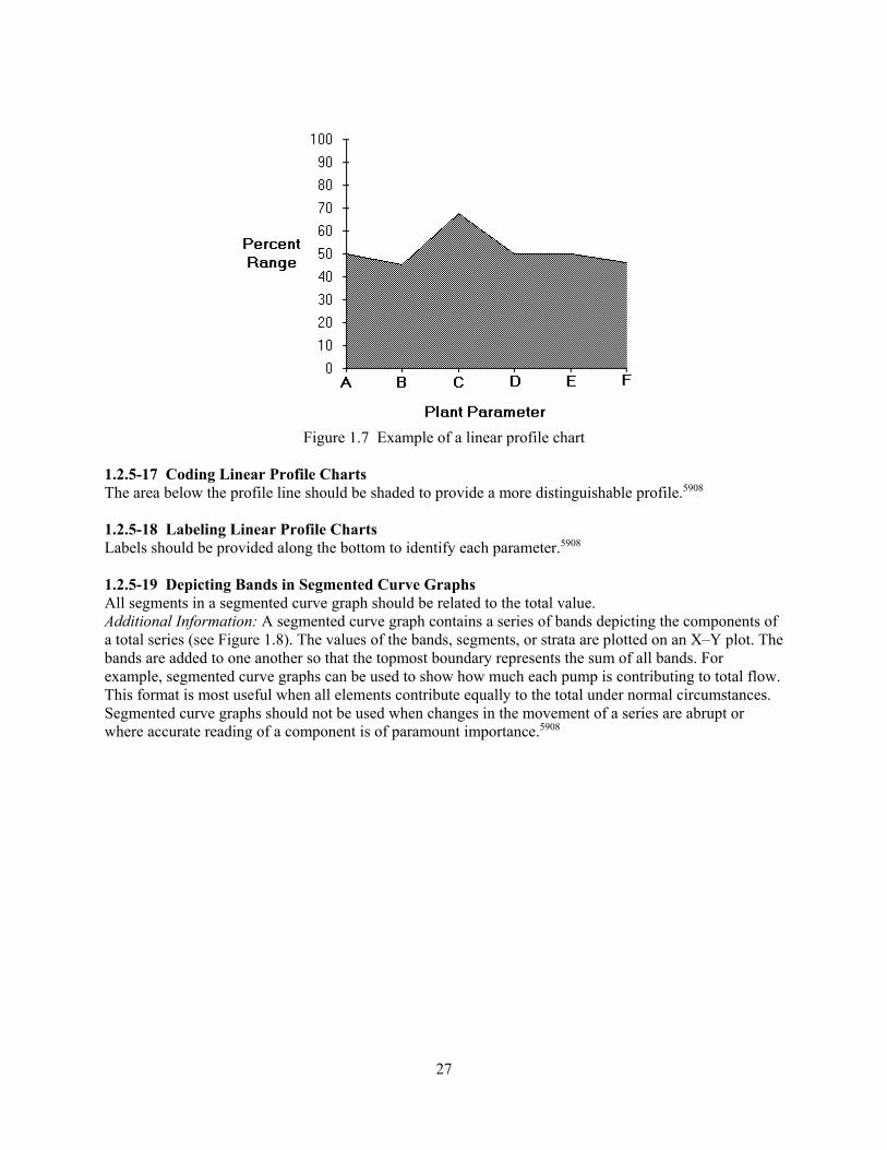
27
Figure 1.7 Example of a linear profile chart
1.2.5-17 Coding Linear Profile Charts The area below the profile line should be shaded to provide a more distinguishable profile.5908 1.2.5-18 Labeling Linear Profile Charts Labels should be provided along the bottom to identify each parameter.5908 1.2.5-19 Depicting Bands in Segmented Curve Graphs All segments in a segmented curve graph should be related to the total value. Additional Information: A segmented curve graph contains a series of bands depicting the components of a total series (see Figure 1.8). The values of the bands, segments, or strata are plotted on an X–Y plot. The bands are added to one another so that the topmost boundary represents the sum of all bands. For example, segmented curve graphs can be used to show how much each pump is contributing to total flow. This format is most useful when all elements contribute equally to the total under normal circumstances. Segmented curve graphs should not be used when changes in the movement of a series are abrupt or where accurate reading of a component is of paramount importance.5908

28
Figure 1.8 Example of a segmented curve graph
1.2.5-20 Ordering Data in Segmented Curve Graphs The data categories in a segmented curve graph should be ordered so that the least variable curves are displayed at the bottom and the most variable at the top. Additional Information: Sometimes there are independent logical grounds for the ordering of data categories. If a segmented curve graph that is constructed on a logical basis produces a confusing irregularity of curves, then it might be better to display the data in some other graphic format. Any irregularity in the bottom curve will “propagate” throughout the curves above it, which will make it difficult for a user to evaluate irregularities in the upper curves.5908 1.2.5-21 Coding Segmented Curve Graphs The different bands of segmented curve graphs should be made visually distinctive by coding, such as by texturing or shading bands.5908 1.2.5-22 Labeling Segmented Curve Graphs Where space permits, the different bands of segmented curve graphs should be labeled directly within the textured or shaded bands.5908 1.2.5-23 Highlighting Scatterplots If some plotted points represent data of particular significance, they should be highlighted to make them visually distinctive from others. Additional Information: Significant data points might be highlighted by bolding, color, blinking, shape coding, or other means, or might be designated by supplementary display annotation.5908 1.2.5-24 Grouping Scatterplots To Show Multiple Relations When relations among several variables must be examined, an ordered group (matrix) of scatterplots should be displayed, each showing the relation between just two variables. Additional Information: The ordering of several scatterplots in a single display might help a user discern relations among interacting variables.5908

29
1.2.5-25 Interactive Analysis of Grouped Scatterplots When scatterplots are grouped in a single display to show relations among several variables, an interactive aid should be provided for analysis so that if a user selects a set of data in one plot, the corresponding data points in other plots will be highlighted. Additional Information: Data selection might be accomplished with a superimposed box of controllable size to define the data set of interest. That technique can exploit the capabilities of interactive graphics to permit a range of data analysis not possible when using printed graphs.5908 1.2.6 Pie Charts 1.2.6-1 Partitioning Partitioning should be limited to five segments or less.5908 1.2.6-2 Labeling Pie Charts Pie chart segments should be labeled directly rather than by a separate legend. If a segment is too small to contain the label, the label should be placed outside the segment with a line from it to the segment. Additional Information: The label should be in a normal orientation for reading text.5908 1.2.6-3 Numeric Annotation of Labels If the task requires precise values, numbers should be added to pie chart segment labels to indicate the percentage or absolute values. Additional Information: Alternative display formats are preferred when users require precise data.5908 1.2.6-4 Highlighting If a particular segment of a pie chart requires emphasis, it should be highlighted by special hatching or displaced slightly from the remainder of the pie.5908 1.2.7 Flowcharts 1.2.7-1 Logical Ordering of Decision Options The available decision options should be displayed in logical order. Additional Information: For example, if options represent stages of a process, those stages should be listed in the order in which they would actually occur. The ordering of options should not be determined merely by the amount of space that is conveniently available to display them.5908 1.2.7-2 Single Decision at Each Step Only a single decision should be required at each step. Additional Information: Decisions should not be combined to reduce flowchart size.5908 1.2.7-3 Consistent Ordering of Decision Options When a flowchart is designed so that a user must make decisions at various steps, the available options should be displayed in some consistent order from step to step. Additional Information: For example, “yes” might always be on the left and “no” on the right. Another scheme is always to have the desirable path lead downward and the “problem” paths lead out to the side. Consistent ordering will permit a user to review a flowchart more quickly.5908 1.2.7-4 Availability of Supplemental Information While flowcharts should display only the data immediately required by the user, a simple action should produce more detailed data.5908

30
1.2.7-5 Conventional Path Orientation Flowcharts should be designed so that the path of the logical sequence is consistent with familiar orientation conventions. Additional Information: For example, a logical path could flow from left to right and from top to bottom.5908 1.2.7-6 Flowchart Symbol Set There should be a standard set of flowchart symbols.5908 1.2.8 Mimics and Diagrams 1.2.8-1 Level of Detail Mimics and diagrams should contain the minimum amount of detail required to yield a meaningful pictorial representation. Additional Information: Figure 1.9 shows an example of a mimic display. Unnecessary graphic detail (such as shadowed symbols or very detailed icons) should be avoided.5908
Figure 1.9 Example of a mimic display
1.2.8-2 Component Identification Plant components represented on mimic lines should be identified. Additional Information: Symbols used on mimic displays should conform to the guidelines in Section 1.3.4, “Icons and Symbols.”0700, 5908 1.2.8-3 Line Points of Origin All flow path line origin points should be labeled or begin at labeled components.5908, 0700 1.2.8-4 Line Termination Points All flow path line destination or terminal points should be labeled or end at labeled components.5908, 0700

31
1.2.8-5 Directional Arrowheads Flow directions should be clearly indicated by distinctive arrowheads.5908, 0700 1.2.8-6 Line Coding Flow paths should be coded (e.g., by color or width, or both) to indicate important information. Additional Information: For example, color can be used to differentiate process flow paths: blue may be used to code water lines; white, steam lines; and yellow, oil lines. In general, features of the flow path that change (e.g., the open/close status of valves) should be coded to be more salient than static features.5908,
0700 1.2.8-7 Overlapping Lines Overlapping flow path lines should be avoided. Additional Information: Crossovers should be clearly indicated so that they do not appear as connections.5908, 0700 1.2.8-8 Symbol-Data Integration Where symbols are used to represent equipment components and process flow or signal paths, numerical data should reflect inputs and outputs associated with equipment.5908 1.2.8-9 Aids for Evaluation When users must evaluate information in detail, computer aids for calculation and visual analysis should be provided. Additional Information: For examining the internal structure of a depicted object, for example, it might be helpful to allow a user to request auxiliary displays of specified cross sections or transect diagrams. For more detailed structural analysis of depicted objects, it might be necessary to provide computer aids for calculating area, volume, stresses, and heat transfer.5908 1.2.9 Maps 1.2.9-1 Feature Identification Significant features of a map should be labeled directly on the display unless cluttering or obscuring of other information would result. Additional Information: Labels on a map should be positioned consistently in relation to the displayed features they designate. For example, equipment names might always be placed immediately above the corresponding symbols showing their locations. As a practical matter, map displays can get very crowded. It may not always prove feasible to maintain a consistent placement for labels, with the result that designers will be tempted to put labels wherever they will fit. In such a crowded display, labels may obscure map features and vice versa. Locating and reading labels will be slowed, particularly when map features are displayed closely adjacent to the beginning of labels. Under these circumstances, some other approach to map labeling should be considered to avoid crowding.5908 1.2.9-2 Consistent Orientation When several different maps will be displayed, a consistent orientation should be used so that the top of each map will always represent the same direction. Additional Information: In common use, most maps are oriented so that north is upward.5908 1.2.9-3 User Selectable Orientation The user should be able to select different orientations and reference points.

32
Additional Information: The system should provide the user with a list of the common orientations and reference points. If the map display can be displayed at other workstations, only the display at the user’s workstation should be affected by the selection. The selected orientation should be clearly indicated (e.g., with a label).5908 1.2.9-4 Panning Map Displays When a map exceeds the capacity of a single display frame, users should be able to pan the display over the mapped data to examine different areas of current interest. Additional Information: Panning is preferred to breaking map displays into discrete pages. Some graphic indicator of the position in the overall display of the visible section should be provided when a user pans over an extended display to view different sections.5908 1.2.9-5 Area Coding Codes, such as texture patterns, color, or tonal variations, should be used when different areas of a map must be defined or when geographic distribution of a particular variable must be indicated. Additional Information: It may be desirable to limit area coding to one variable to ensure effective information assimilation. Another approach might be to allow a user to specify which variable will be coded on a map and to change that selection at will, depending upon current task requirements. In some special applications, however, it may be feasible to superimpose several kinds of area coding to permit multivariate data analysis by skilled users.5908 1.2.9-6 Color Tonal Codes Tonal codes (different shades of one color) rather than spectral codes (different colors) should be used when users must make relative judgments for different colored areas of a display. Additional Information: People can order categories along a continuous dimension to match tonal variations in one color, whereas people do not have a natural means of ordering different colors. This recommendation represents an exception to other guidelines advocating distinctive code values. Coding by tonal variation should be considered only for applications where perception of relative differences along a single dimension is more important than perception of absolute values.5908 1.2.9-7 Ordered Coding Where different areas of a map are coded by texture patterns or tonal variation, the darkest or lightest shades correspond to the extreme values of the coded variable. Additional Information: Orderly assignment of code values will help users perceive and remember the categories represented by the code.5908 1.2.9-8 Mapping Nongeographic Data In applications where the geographic distribution of nongeographic data must be displayed, other graphic elements should be added to a map for that purpose. Additional Information: A display for radioactive control, for example, might superimpose plume tracks on a background of geographic coordinates, with supplementary annotation or coding, or both, to indicate such characteristics as track identification, speed, heading, or altitude. Alphanumeric characters might be added to a map to show data, but those will not aid a direct visual comparison across areas in the same way that graphic symbols do. Moreover, alphanumeric data may be confused with labels and other kinds of annotation. For example, a symbol might be displayed in different sizes to indicate a particular measure in different localities, or small stacked bars might be superimposed on the different areas of a map to indicate the local distribution of some data measure.5908 1.2.9-9 Highlighting Data Change When changes in mapped data are significant for a user’s task, auxiliary graphic elements should be included to highlight those changes.

33
Additional Information: For example, auxiliary coding might be needed to indicate vehicular movement on a map showing evacuation routes.5908 1.2.9-10 Aids for Analyzing Maps When the use of mapped data may be complex, computer aids should be provided for data analysis. Additional Information: Computer aids should be provided when a user must judge distances accurately on a map or other graphic display. For an exact measurement, it might be better to allow a user to select (point at) any two points and have the computer read out their separation distance directly. The same technique might be used to determine the direction (bearing) between two points.5908 1.2.9-11 Map and Label Orientation If the map orientation can be changed, the map labels and symbols should remain oriented to the user’s position.6546 1.2.9-12 Map Decluttering The user should be able to rapidly remove noncritical information from a map or map overlay display.6546 1.2.10 Integral and Configural Formats 1.2.10-1 Appropriate Use of Integral Displays Integral formats should be used to communicate high-level, status-at-a-glance information where users may not need information on individual parameters to interpret the display. Additional Information: Since integral displays do not display individual parameters, they are most appropriate for general status monitoring.6633 1.2.10-2 Appropriate Use of Configural Displays Configural formats should be used when operators must rapidly transition between high-level functional information and specific parameter values. Additional Information: Configural displays provide lower level information, such as parameter values, and higher-level information that is conveyed through emergent features. Since both are present in a single display, operators can easily move between them.6633 1.2.10-3 Reference Aids for Object Displays A perceptually distinct reference aid should be provided in an object display to support operators in recognizing abnormalities in the object’s characteristics. Additional Information: When a change in an object’s characteristics (e.g., its shape) is the perceptual feature that indicates a fault or abnormal condition, perceptual cues can assist operators in detecting the change. If shape is used, the graphic display should include the normal reference point to which operators can compare the current shape. Reference points are especially useful when the abnormality is slow to evolve, and the integral object is changing slowly.6633 1.2.10-4 Representation of Emergent Features The display elements should be organized so that the emergent features that arise from their interaction correspond to meaningful information about the process or system (e.g., when the aspect of the system represented by the emergent is disturbed, the disturbance is visible in the emergent feature). Additional Information: An emergent feature is a high-level, global perceptual feature generated by interactions among individual parts or graphical elements of a display (e.g., lines, contours, and shapes) to produce perceptual properties, such as symmetries, closure, and parallelism. Displays cannot always be organized to provide emergent features, but they should be considered where feasible.6633 1.2.10-5 Levels of Emerging Features

34
The emergent features or patterns within the display should be nested (from global to local) in a way that reflects the hierarchical structure of the process. Additional Information: High-order aspects of the process (e.g., at the level of functional purpose or abstract function) should be reflected in global display features; lower order aspects of the process (e.g., functional organization) should be reflected in local display features.6633 1.2.10-6 Salience of Emerging Features Each emergent feature should be clearly distinguishable from other emergent features and from information on individual parameters. Additional Information: For example, users’ perceptions of plant status can be enhanced by shading the area within a feature. 5908, 6633 1.2.10-7 Reference Aids for Configural Displays A configural display should provide a perceptually distinct reference aid to support operators in recognizing abnormalities in emergent features. Additional Information: When a change in an object’s characteristics (e.g., its shape) is the perceptual feature that indicates a fault or abnormal condition, perceptual cues can assist operators in detecting the change. If shape is used, the display graphic should include the normal reference point against which operators can compare the current one. Reference points are especially useful when the abnormality is slow to evolve, and the integral object is slowly changing. Recognition of abnormalities can also be aided by having normal conditions represented by regular, symmetrical shapes and abnormal conditions indicated by asymmetrical shapes. 5908, 6633 1.2.10-8 Representation of Individual Parameters Each relevant process parameter should be represented by a perceptually distinct element within the display.6633 1.2.10-9 Use of Lower Level Information The display should support the user in performing tasks requiring lower level information. Additional Information: When the operator must perform tasks using lower level information, the display should provide such support. For example, if precise information about a variable is desirable, then a scale or digital information should be provided. Scales should be labeled with the names of the displayed parameters.5908, 6633 1.2.10-10 Complexity The emergent features and their interactions should not be so complex as to be susceptible to misinterpretation. Additional Information: The value of emergent features is that they provide a direct perception of higher level information. They substitute perception for mental calculation. The shift toward perceptual cognition requires careful design, so that misunderstandings are unlikely to occur.6633 1.2.11 Graphic Instrument Panels 1.2.11-1 Display Range Coding Zones indicating operating ranges should be color coded by edge lines or wedges for circular scales. Additional Information: Zones can be used to indicate operating ranges, off-normal levels, and dangerous levels.5908 1.2.11-2 Location of Zero When check-reading positive and negative values on rotary meters (circular displays), the zero or null position should be at 12 o’clock or 9 o’clock.

35
Additional Information: With a matrix of circular displays, deviations from a 9 o’clock null position are easily detected in check reading. Zero should appear at the 12 o’clock position on multirevolution dials.5908 1.2.11-3 Pointer Orientation The pointer on fixed scales should extend from the right of vertical scales and from the bottom of horizontal scales.5908 1.2.11-4 Pointer Obscurement The pointer on fixed scales should extend to but not obscure the shortest graduation marks.5908 1.2.11-5 Tick Mark Separation Tick marks should be separated by at least 1.75 millimeters (0.07 inches) for a viewing distance of 28 inches (71 centimeters) under low illumination. Additional Information: Low illumination is less than 3.5 candelas per square meter (cd/m2) (1.0 foot-lamberts (ft-L)).5908 1.2.11-6 Number of Tick Marks Scales should not be cluttered with more marks than necessary for precision.5908 1.2.12 Speech Displays 1.2.12-1 Limits on Spoken Messages Speech should be limited to only a few messages. Additional Information: Spoken messages would not be useful, for example, if many messages might be given at one time or for conveying a lengthy list of menu options.5908 1.2.12-2 Message Repeat Capability The user should be able to have spoken messages repeated.5908 1.2.12-3 Simple Spoken Messages Messages should be short and simple. Additional Information: If a user does not understand a written message, it can be reread. That is not as easy with spoken messages, even though a REPEAT function should be provided. A better approach is to restrict the use of speech outputs to short and simple messages. If a user who may not be watching a display must be given long or complex messages, it is probably better to provide a simple auditory signal such as a chime, and then display the messages visually for the user to read. In general, users will understand complex messages better when they see them displayed than when they hear them.5908 1.2.12-4 Type of Voice A distinctive and mature voice should be used.5908 1.2.12-5 Delivery Style Spoken messages should be presented in a formal, impersonal manner.5908 1.2.12-6 Word Selection Words in a spoken message should be concise, intelligible, and appropriate for the information presented. Additional Information: Where possible, words that rhyme or may confuse message interpretation should not be part of the spoken lexicon or should not be presented within the same message. Use of slang should be avoided. Words with more than one syllable should be used. Alphanumeric data should be presented using phonetic alphabets (e.g., “Whiskey Zebra three two seven” should be used in preference
36
to “WZ327” where the “Z” and “3” are too phonetically similar.5908 1.2.12-7 Spoken Message Priority A spoken message priority system should be established such that more critical messages override the presentation of messages having lower priority. Additional Information: If two or more incidents or malfunctions occur simultaneously, the message having the higher priority should be given first. The remaining messages should follow in order of priority. In the event of a complete subsystem failure, the system should integrate previous messages using electronic gating and report the system rather than the component failure.5908 1.2.12-8 Distinctive Spoken Warnings If speech is used to provide warnings as well as other forms of user guidance, spoken warnings should be easily distinguishable from routine messages. Additional Information: For example, speech output used to identify emergency conditions might use some distinctive voice or preface each warning message with some other distinctive auditory alert signal, or both. In some applications, computer-generated speech might be useful for providing a few short and simple warnings. However, if speech output is also used for other purposes, then the warning messages should be distinctive.5908 1.2.12-9 Intensity of Speech Presentation Speech signal intensity should be clearly audible for the expected ambient noise environment. Additional Information: For critical messages, speech should be at least 20 decibels (dB) above the speech interference level at the operating position of the intended receiver. Signal-to-noise ratios should be at least 5:1. Audio signal power should be approximately 300 milliwatts at the listener’s ear. Speech signals should fall within the range of 200 to 6100 hertz (Hz).5908 1.3 Display Elements 1.3.1 Alphanumeric Characters 1.3.1-1 Conventional Use of Mixed Case Text to be read (except labels) should be presented using uppercase and lowercase characters. Additional Information: Reading text is easier and faster when capitalization is used conventionally to start sentences and to indicate proper nouns and acronyms. There are several exceptions, however. An item intended to attract the user’s attention, such as a label or title, can be displayed in uppercase. In addition, uppercase should be used when lowercase letters will have decreased legibility (e.g., on a display terminal that cannot show true descenders for lowercase letters).5908 1.3.1-2 Font Style A clearly legible font should be used. Fonts should have true ascenders and descenders, uniform stroke width, and uniform aspect ratio. Additional Information: Preference should be given to simple styles. Script and other highly stylized fonts (e.g., shadow, calligraphy) should be avoided. Avoid typefaces that have extended serifs, internal patterns, or stripes; are italicized, stenciled, shadowed, or 3-dimensional; appear like handwritten script or like Old English script; or are distorted to look tall and thin or wide and fat. The basic evaluation criterion for font selection should be legibility.5908, 0700 1.3.1-3 Distinguishability of Characters For a given font, it should be possible to clearly distinguish between the following characters: X and K, T and Y, I and L, I and 1, O and Q, O and 0, S and 5, and U and V.5908

37
1.3.1-4 Character Size for Text Readability The height of characters in displayed text or labels should be at least 16 minutes of arc and the maximum character height should be 24 minutes of arc. Additional Information: Character heights of 20 to 22 minutes of arc are preferred for reading tasks. Slightly smaller characters are acceptable in high-contrast panel labels (see Section 11.4.1.5, “Label Lettering”). Characters should not be larger than 45 minutes of arc when groups of characters are displayed. Minutes of arc can be converted into height as follows:
Height = 6.283D(MA)/21600
where MA is minutes of arc, and D is the distance from the user to the screen.5908 1.3.1-5 Character Height-to-Width Ratio For fixed (as opposed to proportionally spaced) presentations, the height-to-width ratio should be between 1:0.7 and 1:0.9. Additional Information: For proportionally spaced presentations, a height-to-width ratio closer to 1:1 should be permitted for some characters; for example, the capital letters M and W. The height-to-width ratio of a given character is the vertical distance between the top and bottom edges, and the left and right edges of a nonaccented capital letter. Some letters, however, are customarily seen as narrower than are others. For example, in a given character set, the letter I, and sometimes the letter J, appear narrower than M and 2. Lowercase letters may similarly vary in width. Accordingly, the height-to-width ratio of a given character set should be the modal character width—that is, the width that occurs most often—in the set of capital letters. These measurements are to be made at the same luminance level as the resolution measurement.5908 1.3.1-6 VDU Character Format A 4x5 (width-to-height) character matrix should be the minimum matrix used for superscripts and for numerators and denominators of fractions that are to be displayed in a single character position. Additional Information: A 5x7 (width-to-height) character matrix should be the minimum matrix used for numeric and uppercase-only presentations. The vertical height should be increased upward by two dot positions if diacritical marks are used. A 7x9 (width-to-height) character matrix should be the minimum matrix for tasks that require continuous reading for context, or when individual alphabetical character legibility is important, such as in proofreading. The vertical height should be increased upward by two dot (pixel) positions if diacritical marks are used. If lowercase is used, the vertical height should be increased downward by at least one dot (pixel) position, preferably two or more, to accommodate descenders of lowercase letters. Stroke width should be greater than 1/12 of the character height. A stroke width may be more than one pixel wide.5908 1.3.1-7 Intercharacter Spacing Horizontal separation between characters or symbols should be between 10 and 65 percent of character or symbol height. Additional Information: Separation should not be less than 25 percent of character height when any of the following degraded conditions exists: (1) when character width is less than 85 percent of height, (2) when character luminance in less than 12 ft-L, (3) when luminance contrast is less than 88 percent, (4) when display is more than 35 degrees left or right of the straight-ahead line of sight, and (5) when the visual angle subtended by the character or symbol height is less than 15 minutes of arc.5908, 0700
38
1.3.2 Abbreviations and Acronyms 1.3.2-1 Avoiding Abbreviations Abbreviations should be avoided (except when terms are commonly referred to by their initialisms (e.g., safety parameter display system (SPDS)). Additional Information: When abbreviation is necessary due to space constraints, the words chosen for abbreviation should be those that are commonly known in their abbreviated form, or those words with abbreviations that can be unambiguously interpreted. To indicate that there is low pressure in the condensate storage tank, the use of “CST Pressure Low” would be acceptable, but “Condensate Storage Tank Prssr Lw” is not a good abbreviation. If the user enters an abbreviation for a command name, the system should use the same abbreviation when referring to that command in messages or prompts. The use of abbreviations or contractions in output text should be avoided.5908, 0700 1.3.2-2 Abbreviation Rule When defining abbreviations that are not common to the user population, a simple rule should be used that users understand and recognize. Additional Information: Abbreviation by truncation is the best method, except when word endings convey important information. When a truncation rule is used, abbreviations are easy to derive and easy for a user to decode. If an abbreviation deviates from the consistent rule, it may be helpful to give it some special mark whenever it is displayed.5908 1.3.2-3 Distinctive Abbreviations Abbreviations should be distinctive so that abbreviations for different words are distinguishable.5908 1.3.2-4 Punctuation of Abbreviations Abbreviations and acronyms should not include punctuation. Additional Information: For example, SPDS is preferred over S.P.D.S. Punctuation should be retained when needed for clarity (e.g., “4-inch diameter pipe” rather than “4 in diameter pipe.” 5908 1.3.2-5 Easily Remembered Arbitrary Codes When the user must remember arbitrary codes, characters should be grouped in blocks of three to five characters, separated by a minimum of one blank space or other separating character, such as a hyphen or slash. Additional Information: Arbitrary codes are alphanumeric characters without natural organization. When a code is meaningful, such as a mnemonic abbreviation or a word, it can be longer.5908 1.3.2-6 Avoid O and I in Arbitrary Codes The use of the letters O and I in a nonmeaningful code should be avoided because they are easily confused with the numbers 0 (zero) and 1 (one), respectively.5908 1.3.2-7 Combining Letters and Numbers in Arbitrary Codes When codes combine both letters and numbers, letters should be grouped together and numbers grouped together rather than interspersing letters with numbers. Additional Information: For example, letter-letter-number (“HW5”) will be read and remembered somewhat more accurately than letter-number-letter (“H5W”).5908
39
1.3.3 Labels 1.3.3-1 Group Labels Each individual aspect of a display (e.g., data group, field, or message) should contain a distinct, unique, and descriptive label.5908, 0700 1.3.3-2 Meaningfulness of Labels Labels should be meaningful words or accepted technical terms. Additional Information: Labels should describe the contents of the display accurately and concisely, without unnecessary words or characters. Whenever space permits, the label should consist of the entire word or sequence of words that describe the displays. If abbreviations are necessary, users should readily understand their meanings.5908 1.3.3-3 Label Formats Label formats should be consistent across and within displays.5908 1.3.3-4 Consistent Wording of Labels Labels should be worded consistently, so that the same item is given the same label whenever it appears. Additional Information: Consistent grammatical format for different labels should also be employed (i.e., single words or phrases for some labels and short sentences for others, or verbs for some and nouns for others should not be used).5908 1.3.3-5 Distinctive Labels Labels should be uniquely and consistently highlighted, capitalized, or otherwise emphasized to differentiate them from other screen structures and data. Additional Information: The technique used should be easily distinguished from that used to highlight or code emergency or critical messages, such as by bolding, underlining, and use of capitals.5908, 0700 1.3.3-6 Label Separation Labels should be separated from one another by at least two standard character spaces.5908 1.3.3-7 Normal Orientation for Labels The annotation of graphic displays, including labels for the axes of graphs, should be displayed in a normal orientation for reading text. Additional Information: Users should be presented with horizontally displayed labels, even for the vertical axis of a graph. A conventional text orientation of labels will permit faster, more accurate reading. While it may be possible to tilt the page to read a disoriented label on a printed page, a user usually cannot tilt a VDU display screen.5908, 0700 1.3.3-8 Label Content for User Options When presenting a list of user options, labels should reflect the question or decision being posed to the user.5908, 0700 1.3.3-9 Labels for Graphical Objects The label for a specific graphical object (e.g., an icon) should be placed in close proximity to the object. Additional Information: When possible, the label should be on the component if it does not obscure the component. If multiple component parts of the graphic object are close to the label, a line should point from the label to the associated part.5908

40
1.3.4 Icons and Symbols 1.3.4-1 Appropriate Use of Icons The primary use of icons in graphic displays should be to represent actual objects or actions. Additional Information: Icons may be used to graphically represent operations, processes, and data structures and may be used as a means of exercising control (e.g., by selecting an icon and commanding operations) over system functions, components, and data structures.5908 1.3.4-2 Iconic Representation Icons should be designed to look like the objects, processes, or operations they represent, by use of literal, functional, or operational representations. Additional Information: Some pictorial symbols have conventional meanings within a user population, which should be followed to ensure their correct interpretation. The following are examples of representations: literal, a figure of a pump; functional, a figure of a file cabinet; and operational, a hand on a switch.5908 1.3.4-3 Simple Design Icons should be simple, closed figures when possible. Additional Information: When icons are too visually complex, they are not quickly recognized. This eliminates the primary advantage of using icons (i.e., quick recognition). Simple, closed figures (i.e., ones with a continuous outside border) are processed more efficiently than are open figures.5908 1.3.4-4 Use of Abstract Symbology Abstract symbols should conform to user conventions or to common electrical and mechanical symbol conventions when user conventions do not exist. Additional Information: Symbols used on displays should not be inconsistent with those of other information sources used in the work area, such as piping and instrumentation diagrams and logic diagrams.5908 1.3.4-5 Distinguishability Each icon and symbol should represent a single object or action and should be easily distinguished from all other icons and symbols. Additional Information: The distinguishing feature between icons should be the external geometric configuration of the icon.5908 1.3.4-6 Consistent Use of Special Symbols Special symbols to signal critical conditions should be used exclusively for that purpose.5908 1.3.4-7 Upright Orientation Icons and symbols should always be oriented upright. 5908 1.3.4-8 No Alternating Words and Symbols Words and symbols should not be used alternately. Additional Information: Alternating use of symbols and words could cause confusion and impair task performance.5908 1.3.4-9 Size Icons and symbols should be large enough for the user to perceive the representation and distinguish it from other icons and symbols. Additional Information: When a displayed symbol of complex shape is to be distinguished from another symbol shape that is also complex, the symbol should subtend not less than 20 minutes of arc at the

41
required viewing distance. VDU-displayed symbols that should be distinguished from other complex shapes should have a minimum of 10 resolution elements for the longest dimension of the symbol.5908, 0700 1.3.4-10 Highlighting An icon or symbol should be highlighted when the user has selected it.5908 1.3.4-11 Labeling Icons Icons should be accompanied by a text label. Additional Information: To the extent that it does not clutter or cause distortion of the icon, the label should be incorporated into the icon itself. When icons are designed such that the label is inside the icon, the number of perceptual objects is reduced, resulting in enhanced processing of the label and the icon. The text label may be omitted for icons having unambiguous meanings to users (e.g., standard piping and instrumentation diagram symbology).5908 1.3.4-12 Labels for Control Option Icons If icons are used to represent control action options, a label indicating the action should be associated with the icon.5908 1.3.5 Numeric Data 1.3.5-1 Number System Numeric values should ordinarily be displayed in the decimal number system. Additional Information: Maintenance, troubleshooting, or configuration tasks may use other systems (e.g., binary, octal, or hexadecimal).5908 1.3.5-2 Leading Zeros Leading zeros in numeric entries for whole numbers should be suppressed. Additional Information: For example, 28 should be displayed rather than 0028. A leading zero should be provided if the number is a decimal with no preceding integer (i.e., 0.43 rather than .43).5908 1.3.5-3 Maintaining Significant Digits A number should be displayed at the number of significant digits required by users to perform their tasks. Additional Information: Arbitrary conventions should not require that displays present more (or fewer) significant digits than necessary. The number of significant digits should be supported by the accuracy of the underlying sensors, instruments, and electronics.5908 1.3.5-4 Display Range Numeric displays should accommodate the variable’s full range. Additional Information: The full range of the variable means highest and lowest values that the variable is expected to take on, under any conditions (normal or emergency operations) for the tasks the display is designed to support.5908 1.3.5-5 Rate of Display Change Digital displays should change slowly enough to be readable.5908 1.3.5-6 Direction of Change in Digital Display If users must rapidly discern directional change, digital displays should be provided with arrows to indicate the direction of change. Additional Information: Rapidly changing digital values are difficult to read, and directional indicators will help the user interpret the direction of trend.5908

42
1.3.5-7 Direct Display of Differences If users must evaluate the difference between two sets of data, the difference should be presented on the display. Additional Information: If it is important for the user to be aware of a discrepancy between two sets of data, the difference should be highlighted on the display.5908 1.3.5-8 Orientation of Numbers All numbers should be oriented upright.5908 1.3.6 Scales, Axes, and Grids 1.3.6-1 Orientation of Scales Numbers on a scale should increase clockwise, left to right, or bottom to top.5908 1.3.6-2 Scale Intervals Nine should be the maximum number of tick marks between numbers. Additional Information: Major and minor graduations should be used if there are up to four graduations between numerals. Major, intermediate, and minor graduations should be used if there are five or more graduations between numerals. The use of these graduations on a conventional meter face is shown in Figure 1.10, while Table 1.2 shows graduation dimensions as a function of viewing distance for a conventional meter face.5908, 0700
Figure 1.10 Graduation dimensions in inches (mm) for 3-foot viewing distance
Table 1.2 Index heights for various viewing distances
Viewing Distance feet (m)
Index Height inches (mm)
Major Intermediate Minor 1.5 (0.5) 0.22 (5.5) 0.16 (4.0) 0.09 (2.0) 3.0 (0.9) 0.40 (10.0) 0.28 (7.0) 0.17 (4.0) 6.0 (1.8) 0.78 (20.0) 0.56(14.0) 0.34 (8.5) 12.0 (3.7) 1.57 (40.0) 1.12 (28.5) 0.65 (16.5) 20.0 (6.1) 2.63 (67.0) 1.87 (47.5) 1.13 (28.5)
43
1.3.6-3 Scaling in Standard Intervals Scales should have tick marks at a standard interval of 1, 2, 5, or 10 (or multiples of 10) for labeled divisions; intervening tick marks to aid visual interpolation should be consistent with the labeled scale interval. Additional Information: Users will find it difficult to interpret scales based on odd intervals. It is not advisable to let the computer divide available scale space automatically if that results in a scale labeled in unfamiliar intervals such as 6 or 13. In special instances, the X-axis might be scaled in odd intervals to show customary divisions, such as 12 months in a year.5908, 0700 1.3.6-4 Circular Scales For one-revolution circular scales, zero should be at 7 o’clock and the maximum value should be at 5 o’clock.5908 1.3.6-5 Axis Labels Axes should be clearly labeled with a description of the parameter represented by the axis. Additional Information: Labels should be displayed in upright orientation on both the X- and Y-axis for ease of reading.5908
1.3.6-6 Identification of Units of Measurement The axis label should include the units of measurement represented by the scale.5908 1.3.6-7 Scaling Conventions Conventional scaling practice should be followed, in which the horizontal X-axis is used to plot time or the postulated cause of an event, and the vertical Y-axis is used to plot the effect. Additional Information: When the X-axis represents time intervals, the labeled scale points should represent the end of each time interval. This consistent usage will aid interpretation of all data plots, including scatterplots, line graphs, and bar charts.5908 1.3.6-8 Consistent Scaling If users must compare graphic data across a series of displays, the same scale should be used for each. Additional Information: Note that, in many applications, it may prove more effective to display data for comparison in a single combined chart, rather than requiring users to compare data across a series of charts. Users will find it difficult to compare data sets that are scaled differently. Moreover, users may overlook differences in labeling and assume that the same scale has been used, even when displayed scales are actually different from one another.5908, 0700 1.3.6-9 Scales Consistent with Function The scales should be consistent with the intended functional use of the data. Additional Information: Scales should be selected to (1) span the expected range of operational parameters, (2) employ appropriate scale-ranging techniques, or (3) be supported by auxiliary wide-range instruments. For example, the monitoring of neutron flux at reactor trip should have a variable scale of 0 to 100 percent of the design value and a time scale resolution of seconds. However, post-trip monitoring may have a variable scale of 0 to 10 percent with a time-scale resolution of minutes. Finally, operational log data of neutron flux may have a time-scale resolution of hours.5908, 0700 1.3.6-10 Linear Scaling A linear scale should be used for displayed data, in preference to logarithmic or other nonlinear methods of scaling, unless it can be demonstrated that nonlinear scaling will facilitate user interpretation of the information. Additional Information: Most users are more familiar with linear scales and will interpret linear scales more accurately than other methods of scaling. However, since logarithmic scales show percentage

44
change rather than arithmetic change, they may be appropriate for some special applications.0800, 5908, 0700 1.3.6-11 Numeric Scales Start at Zero When users must compare aggregate quantities within a display, or within a series of displays, scaling of numeric data should begin with zero. Additional Information: Numerical scales generally should have zero at the bottom as the first number on a vertical scale or at the left as the first number on a horizontal scale. The exceptions to this organization would be: (1) if the numbers are used for naming categories, (2) if zero is not a plausible number on the scale, or (3) if the scale contains negative numbers. If, for any reason, the zero point is omitted, the display should include a clear indication of that omission, and the scales on which quantities are to be compared should be the same.5908 1.3.6-12 Display of Origin When graphed data represent positive numbers, the graph should be displayed with the origin at the lower left, such that values on an axis increase as they move away from the origin of the graph. Additional Information: When the data include negative values and the axes must extend in both directions from a zero point, that origin should be displayed in the center of the graph.5908 1.3.6-13 Single Scale on Each Axis Only a single scale should be shown on each axis, rather than including different scales for different curves in the graph. Additional Information: Single-scale graphs will generally permit more accurate reading than graphs displaying several scales. Many users will be confused by multiple-scale graphs and make errors when interpreting them. Moreover, by changing the relative scale factors of multiple-scale graphs, it is possible to change radically their apparent meaning and bias interpretation by users.5908 1.3.6-14 Scaling Against a Reference Index If different variables on a single graph require different scales, they should be scaled against a common baseline index, rather than showing multiple scales. Additional Information: Rather than showing power in megawatts and profits in dollars, both might be graphed in terms of percent change from a baseline. An indexed chart can permit comparisons among different variables when multiple scales would otherwise be needed. However, care should be taken in selecting an appropriate baseline against which to index, to ensure that comparisons will not be biased. Index scaling may also be appropriate for showing the effect of a single variable where units of measurement change in real value with time.5908, 0700 1.3.6-15 Indication of Scale When a graphic display has been expanded from its normal coverage, some scale indicator of the expansion factor should be provided. Additional Information: Scale ranges may be expanded (or contracted) by multiplying or dividing indicated scale values by powers of ten. All such scales should be clearly marked as to whether the indicated values should be multiplied or divided and the factor to be used (e.g., 10, 100, or 1000).5908 1.3.6-16 Manual Rescaling Users should be able to manually change the scale to maintain an undistorted display under different operating conditions.0800 1.3.6-17 Indication of Automatic Rescaling If the system is designed to automatically change scale, an alert should be given to the user that the change is being made.

45
Additional Information: Automatic rescaling can lead to confusion if the change in scale is not recognized.0800 1.3.6-18 Aids for Scale Interpolation If interpolation must be made or where accuracy of reading graphic data is required, computer aids should be provided for exact interpolation. Additional Information: It might suffice, for example, to allow users to request a fine grid as an optional display feature. It might be better to display vertical and horizontal rulers that a user could move to intersect the axes of a chart. It might prove best simply to let a user point at any data item and have the computer label that item with a readout of its exact value(s).5908 1.3.6-19 Unobtrusive Grids When grid lines are displayed, they should be unobtrusive and not obscure data elements (e.g., curves and plotted points). Additional Information: Grid lines should be thinner than data curves and should be invisible behind depicted objects and areas. Heavy grid lines may conceal details of plotted data. Electronic displays offer more flexibility than printed graphs. Grids can be displayed or suppressed by user selection. For reading the value of a particular data point, perhaps no grid is needed at all. A user might simply ask the computer to display the value of any selected point.5908 1.3.6-20 Numbering Grids Graphs should be constructed so that numbered grids are bolder than unnumbered grids. Additional Information: If 10-grid intervals are used, the fifth intermediate grid should be less bold than the numbered grid but bolder than the unnumbered grids.5908, 0700 1.3.6-21 Discontinuous Axes When data comparisons of interest fall within a limited range, the scaled axis should emphasize that range, with a break in the displayed axis to indicate discontinuity with the scale origin. Additional Information: Note, however, that a broken axis distorts the displayed value in relation to a base value and so risks confusing users. In effect, a user will expect that a scale marked in regular intervals will continue in a consistent fashion. If an axis must be broken, the break should be labeled clearly, perhaps with some indicator that extends across the displayed graph.5908 1.3.6-22 Duplicate Axes When scaled data will contain extreme values, duplicate axes should be displayed, so that the X-axis appears at both the top and bottom and the Y-axis at both the left and right sides of the graph. Additional Information: Extreme data values may be located far from conventionally placed axes. When duplicate axes are displayed at the top and right side, users will find it easier to read the extreme values.5908 1.3.6-23 Restricted Use of Three-Dimensional Scaling Unless required, use of three-dimensional scales (i.e., where a Z-axis is added to the display) should be avoided. Additional Information: Showing a Z-axis on a VDU display that is limited to two actual dimensions will confuse many users. If 3-dimensional scaling is employed, a consistent method of representation (e.g., isometric or orthographic projection, perspective drawing, or triangular coordinate grid) should be used. It is often possible in graphic display to show a third dimension through use of auxiliary coding (e.g., color or shape coding or supplementary annotation), which may prove more effective than trying to represent a third spatial dimension pictorially.5908

46
1.3.7 Borders, Lines, and Arrows 1.3.7-1 Line Types Meaningful differences between lines appearing in graphic displays, such as flow paths, should be depicted by using various line types (e.g., solid, dashed, dotted, and widths). Additional Information: Three or four line types may be readily distinguished, and two or three line widths may be readily distinguished. A line displayed on a VDU will appear continuous if the separation between resolution elements is less than 1 minute of arc. To provide the illusion of continuity, graphic lines should contain a minimum of 50 resolution elements per inch.5908, 0700 1.3.7-2 Conventional Use of Arrows In flow charts and other graphics displays, arrowheads should be used in a conventional fashion to indicate directional relations in the sequential links between various elements.5908 1.3.7-3 Restricted Use of Borders The display should not use unnecessary borders. Additional Information: Borders can add visual clutter to a display and add to information processing time. Borders should only be used for functional purposes, such as to facilitate grouping.5908 1.3.7-4 Bordering Single Blocks A border should be used to improve the readability of a single block of numbers or letters.5908 1.3.7-5 Distinctive Borders Around Critical Information If several labels or messages are clustered in the same area, distinctive borders should be placed around the critical ones only.5908 1.3.8 Color 1.3.8-1 Use of Color Where color is used for coding, it should be employed conservatively and consistently. Additional Information: The number of colors used for coding should be kept to the minimum needed for providing sufficient information. Once colors are assigned a specific use or meaning, no other color should be used for the same purpose. Note that the same color may be used for different purposes so long as its context of use in unambiguous (e.g., color coding high-priority alarms red and valve status of open as red). Casual, arbitrary use of colors on every display may cause displays to appear “busy” or cluttered. Casual use of color will also reduce the likelihood that significant color coding on particular displays will be interpreted appropriately and quickly by a user.5908, 0700 1.3.8-2 Color Coding for Discrete Data Categories When a user must distinguish rapidly among several discrete categories of data, a unique color should be used to display the data in each category. Additional Information: Color coding of discrete categories (e.g., setpoint values and actual values) is particularly useful when data items are dispersed on a display. With some display equipment now providing a wide range of different colors, designers may be tempted to exploit that capability by using many different colors for coding. However, such a capability is not useful for coding discrete categories, except that it may allow a designer to select more carefully the particular colors to be used as codes.5908 1.3.8-3 Color Coding for Relative Values When the relative rather than the absolute values of a variable are important, gradual color changes as a tonal code should be used to show the relative values of a single variable.

47
Additional Information: For example, in displaying tank depth, a saturated blue might be used to show the deepest point, with gradually desaturated blues to show decreasing depth. Gradual color changes should not be used when absolute values are important or to code data into discrete categories. For example, gradual color changes should not be used to indicate the level of a storage tank as it is drained or filled. Instead, a set of discrete codes indicating dangerous and acceptable levels may be more appropriate.5908 1.3.8-4 Color Coding To Draw Attention Brighter or more saturated colors should be used when it is necessary to draw a user’s attention to critical data. Additional Information: Both intensity and saturation should be used to draw a user’s attention to critical data. Although saturated or intense hues are useful for drawing a user’s attention, their overuse will result in a display that is garish and difficult to view for long periods.5908 1.3.8-5 Color Selection Colors for coding should be based on user conventions with particular colors. Additional Information: Color codes should conform to color meanings that already exist in the user’s job. Color codes employing different meanings will be much more difficult to use. Table 1.3 provides general nuclear plant color meanings.5908, 0700
Table 1.3 Associations and related characteristics for colors typically used in panel design
Color Associated Meanings
Attention-Getting Value
Contrasts Well With
Red Unsafe Danger Alarm state Hot Open/flowing1 Closed/stopped1
Good White
Yellow Hazard Caution Abnormal State Oil
Good Black Dark Blue
Green Safe Satisfactory Normal state Open/flowing1
Closed/stopped1
Poor White
Light blue (cyan)
Advisory Aerated water Cool
Poor Black
Dark Blue Advisory Untreated water
Poor White
Magenta2 Alarm state Good White White Advisory
Steam Poor Green
Black Red Dark blue Magenta
Black Background Poor White Light blue Yellow

48
1 Meanings associated with red and green colors differ, depending on past experience. Personnel with previous fossil fuel plant experience typically associate an open/flowing state with red and a closed/stop state with green, but reverse associations typically exist for personnel with previous Navy experience.
2 Magenta on yellow is the nuclear industry standard for radiation caution. 1.3.8-6 Pure Blue Pure blue on a dark background should be avoided for text, for thin lines, or for high-resolution information.5908 1.3.8-7 Easily Distinguishable Colors When color coding is used to group or highlight displayed data, all of the colors in the set should be readily distinguishable from each other. Additional Information: Table 1.4 identifies the wavelengths of colors that can be easily distinguished. For example, on a light background: red, dark yellow, green, blue, and black, and on a dark background: desaturated red, green, and blue, plus yellow and white. If color coding is applied to symbols that subtend small visual angles, which makes color perception difficult, there will be a special need to limit the number of colors used. If colors are used for displaying text, care should be taken to ensure that colored letters are legible as well as distinguishable. Since the perception of color depends on ambient lighting, the use of color should be evaluated in situ under all expected lighting conditions. When color coding is used to distinguish displayed information or make it conspicuous, all colors in the set should differ from one another by E distances (1976 Commission Internationale de l'Eclairage (CIE) (International Commission on Illumination) Uniform Color Space (UCS) L*u*v*) of 40 units or more. This approach will make available at least 7 to 10 simultaneous colors. Increasing ambient illuminance decreases color purity and, consequently, color discriminability. Accordingly, color measurements should be made under the presumed ambient lighting conditions in which the display will be used. The discriminability of pairs of colors depends on their differences in chrominance and luminance. While an entirely satisfactory metric does not exist that combines these attributes into a single assessment of total color difference, an estimate can be derived by calculating the weighted difference between the locations of the colors in the (CIE UCS L*u*v). Note that this estimate should be used only to ensure discriminability of colors of relatively high luminance. Severe nonlinearities in the UCS limit the usefulness of this metric for colors having small luminance differences. In addition, the specification of small color differences should be treated with caution because of the inherent lack of color uniformity on most VDUs. For full color displays, the reference white can be taken as the white on the display obtained with full-intensity red, D6500 K° or 9300 K°. Equation 1.1 contains the difference formula.5908
Table 1.4 Representative set of candidate colors for use in panel design
Color Dominant Wavelength
(in nanometers) Munsell Code
Red 610 5.0R/3.9/15.4 Yellow 582 3.3Y/8.0/143 Green 515 3.2G/4.9/11.1 Light blue (cyan) 494 2.7GB/7.9/6.0 Dark blue 476 2.9PB/4.1/10.4 Magenta 430 6.5P/4.3/9.2 White 2.5PB/9.5/0.2 Black N/0.8
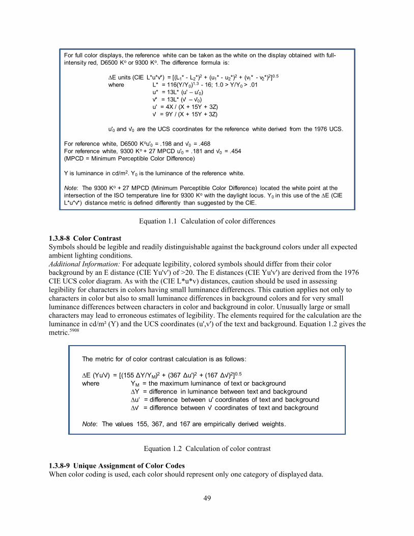
49
Equation 1.1 Calculation of color differences 1.3.8-8 Color Contrast Symbols should be legible and readily distinguishable against the background colors under all expected ambient lighting conditions. Additional Information: For adequate legibility, colored symbols should differ from their color background by an E distance (CIE Yu'v') of >20. The E distances (CIE Yu'v') are derived from the 1976 CIE UCS color diagram. As with the (CIE L*u*v) distances, caution should be used in assessing legibility for characters in colors having small luminance differences. This caution applies not only to characters in color but also to small luminance differences in background colors and for very small luminance differences between characters in color and background in color. Unusually large or small characters may lead to erroneous estimates of legibility. The elements required for the calculation are the luminance in cd/m² (Y) and the UCS coordinates (u',v') of the text and background. Equation 1.2 gives the metric.5908
Equation 1.2 Calculation of color contrast 1.3.8-9 Unique Assignment of Color Codes When color coding is used, each color should represent only one category of displayed data.
For full color displays, the reference white can be taken as the white on the display obtained with full-intensity red, D6500 Ko or 9300 Ko. The difference formula is:
∆E units (CIE L*u*v*) = [(L1* - L2*)2 + (u1* - u2*)2 + (v1* - v2*)2]0.5
where L* = 116(Y/Y0)1.3 - 16; 1.0 > Y/Y0 > .01u* = 13L* (u' – u'0)v* = 13L* (v' – v'0)u' = 4X / (X + 15Y + 3Z)v' = 9Y / (X + 15Y + 3Z)
u'0 and v'0 are the UCS coordinates for the reference white derived from the 1976 UCS.
For reference white, D6500 Kou'0 = .198 and v'0 = .468For reference white, 9300 Ko + 27 MPCD u'0 = .181 and v'0 = .454(MPCD = Minimum Perceptible Color Difference)
Y is luminance in cd/m2. Y0 is the luminance of the reference white.
Note: The 9300 Ko + 27 MPCD (Minimum Perceptible Color Difference) located the white point at the intersection of the ISO temperature line for 9300 Ko with the daylight locus. Y0 in this use of the ∆E (CIE L*u*v*) distance metric is defined differently than suggested by the CIE.
The metric for of color contrast calculation is as follows:
∆E (Yu'v') = [(155 ΔY/YM)2 + (367 Δu')2 + (167 Δv')2]0.5
where YM = the maximum luminance of text or background∆Y = difference in luminance between text and background∆u‘ = difference between u' coordinates of text and background ∆v‘ = difference between v' coordinates of text and background
Note: The values 155, 367, and 167 are empirically derived weights.

50
Additional Information: Color will prove the dominant coding dimension on a display. If several different categories of data are displayed, for example, in red, they will have an unwanted visual coherence that may hinder proper assimilation of information by a user.5908
1.3.8-10 Redundant Color Coding Color coding should be redundant with some other display feature. Additional Information: Pertinent information should be available from some other cue in addition to color. Displayed data should provide necessary information even when viewed on a monochromatic display terminal or hardcopy printout, or when viewed by a user with color vision impairment.5908, 0700 1.3.8-11 Unplanned Patterns from Color Coding Color coding should not create unplanned or obvious new patterns on the screen.5908 1.3.8-12 Red-Green Combinations Whenever possible, red and green colors should not be used in combination. Additional Information: Use of red symbols on a green background should especially be avoided.0700 1.3.8-13 Chromostereopsis Simultaneous presentation of both pure red and pure blue on a dark background should be avoided. Additional Information: Such a presentation may result in chromostereopsis (an uncomfortable 3-dimensional effect).5908 1.3.8-14 Pure Red Dominant wavelengths above 650 nanometers in displays should be avoided.5908
1.3.9 Size, Shape, and Pattern Coding 1.3.9-1 Limited Use of Size Coding Size coding should be used only for applications where displays are not crowded. Additional Information: Size coding is achieved by varying the size of displayed alphanumerics, labels, and other symbols.5908 1.3.9-2 Size Variations A maximum of three size levels should be used. The major dimensions of the larger symbol should be at least 150 percent of the major dimension of the smaller symbol. Additional Information: An increase in symbol height must usually be accompanied by a proportional increase in width to preserve a constant aspect ratio and so facilitate symbol recognition.5908 1.3.9-3 Size Coding Proportional to Data Value When the symbol size is to be proportional to the data value, the scaled parameter should be the symbol area rather than a linear dimension such as diameter. Additional Information: A user’s judgment of the “size” of a symbol will correspond more closely to its area than to its diameter.5908 1.3.9-4 Length Coding For length coding, the maximum number of levels should be six (preferably no more than three).5908 1.3.9-5 Establishing Standards for Shape Coding When shape coding is used, codes should be based on established standards or conventional meanings. Additional Information: Coding with geometric shapes should be used to help users differentiate different categories of data on graphic displays. Although shape codes can often be mnemonic in form, their

51
interpretation will generally rely on learned association as well as immediate perception. Existing user standards must be considered.5908 1.3.9-6 Clearly Discriminable Shapes Shapes used in coding for data groups should be clearly distinguishable. Additional Information: When shape coding is used, the shapes should vary widely and the number of basic shapes should be limited. For example, the elements of one group in a display might be triangles and the elements of a second group might be circles. Approximately 15 different shapes can be readily distinguished, provided the shapes are properly designed. Under adverse viewing conditions, no more than 6 shapes should be used. When needed, other highlighting and graphic techniques (color, filled or unfilled, and other “modifiers”) should be used to display different states or qualities of the basic symbol.5908, 0700 1.3.9-7 Simple Pattern Codes When patterns are used to code displayed areas, simple rather than elaborate patterns should be used. Additional Information: To aid visual discrimination and identification, simple patterns, such as hatching, should be employed rather than complex patterns.5908 1.3.9-8 Pattern Coding of Extreme Values Pattern density should vary with the value of the coded variable so that the least dense pattern is associated with one extreme and the most dense pattern with the other extreme.5908 1.3.10 Highlighting by Brightness and Flashing 1.3.10-1 Easily Recognizable Highlighting Highlighting should be easily recognizable and used to attract the user’s attention to special conditions, items important to decision making or action requirements, or as a means to provide feedback.5908, 0700 1.3.10-2 Minimal Highlighting Highlighting of information should be minimized. Additional Information: A rule of thumb for displays of nominal conditions is to limit the maximum amount of highlighting to 10 percent of the displayed information. If a large proportion of the displayed items are highlighted, the highlighting will no longer be effective for directing the user’s attention.5908 1.3.10-3 Consistency A particular highlighting method should be used consistently. Additional Information: Highlighting methods associated with emergency conditions should not also be used in association with normal conditions.5908, 0700 1.3.10-4 Removing Highlighting If highlighting is used to emphasize important display items, it should be removed when it no longer has meaning. Additional Information: If highlighting identifies an error, that highlighting should be removed when the error is corrected.5908 1.3.10-5 Appropriate Use of Brightness Coding Coding by differences in brightness should be used for applications that require differentiation between only two categories of displayed items on a VDU and up to three on a transilluminated display. Additional Information: Brightness coding should not be used in conjunction with shape or size coding.5908, 0700

52
1.3.10-6 Significance of Brightness Levels High brightness levels should be used to signify information of primary importance, and lower levels should be used to signify information of secondary interest.5908 1.3.10-7 Intensity Levels for Brightness Coding Levels approximating 33 percent and 100 percent of the display luminance should be used for brightness coding. Additional Information: The intensities used should not be less than 20 cd/m² (6 ft-L). Intensity coding should not be used for displays with a maximum display luminance of less than 60 cd/m² (18 ft-L) or more than 100 cd/m² (29 ft-L).5908 1.3.10-8 Inverse Video Inverse video should be used primarily for highlighting in dense data fields or to indicate selection of onscreen objects and information.5908, 0700
1.3.10-9 Appropriate Use of Flash Coding Flashing should be used when a displayed item implies an urgent need for attention or action but not in displays requiring attention to detail or reading of text. Additional Information: An “off” condition should never be used to attract attention to a message. Flashing should not be used to highlight routine information. Flashing should only be used as an alerting or warning code. If used sparingly, flashing symbols are effective in calling a user’s attention to displayed items of unusual significance. Flash coding generally reduces search times, especially in dense displays.5908, 0700 1.3.10-10 Flash Coding for Text When a user must read a displayed item that is flash coded, an extra symbol such as an asterisk or arrow to mark the item should be used, and the marker symbol should flash rather than the item itself. Additional Information: This practice will draw attention to an item without detracting from its legibility. Flashing characters may have somewhat reduced legibility and may cause visual fatigue.5908 1.3.10-11 Small Area Only a small area of the screen should flash at any time.5908 1.3.10-12 Coding by Flash Rate No more than two flash rates should be used. Additional Information: The differences between the two flash rates should be at least 2 Hz. The slow flash should not be less than 0.8 Hz, and the fast flash rate should not be more than 5 Hz. The percentage of time that the image is “on” should be greater than or equal to the time that it is “off.” A 50-percent duty cycle is preferred. When a single blink rate is used, the rate should be roughly 2–3 blinks per second with a minimum of 50 msec “on” time between blinks.5908, 0700 1.3.10-13 Flash Suppression Event acknowledgement or flash suppression keys should be provided.5908 1.3.10-14 Long-Persistence Phosphor Displays Flashing should not be used with long-persistence phosphor displays.5908 1.3.10-15 Flash Rate for Critical Information When two rates are used, the higher rate should apply to the more critical information.0700
53
1.3.11 Auditory Coding 1.3.11-1 Appropriate Use of Auditory Signals Auditory signals should alert the user to situations that require attention, such as an incorrect input action or a failure of the HSI to process an input from the user. Additional Information: An auditory signal should provide users with a greater probability of detecting the triggering condition than their normal observations would provide in the absence of the auditory signal.5908 1.3.11-2 Dedicated Use Systems used to transmit nonverbal auditory signals should be used only for that purpose.0700 1.3.11-3 Localization Auditory signals should provide localization cues that direct users to those control room workstations where attention is required.0700 1.3.11-4 Selection Auditory signals should be selected to avoid interference with other auditory sources, including verbal communication.0700 1.3.11-5 Signal Priority Distinction Advisory or caution signals should be readily distinguishable from warning signals and used to indicate conditions requiring awareness but not necessarily immediate action.5908 1.3.11-6 Association with Visual Warnings Auditory alerts, as well as caution and warning sounds, should accompany visual displays. Additional Information: The audio signal should be used to alert and direct attention to the appropriate visual display.5908 1.3.11-7 Unique Signal-Event Association Once a particular auditory signal code is established for a given operating situation, the same signal should not be designated for some other display. Additional Information: The meaning of each auditory signal should be clear and unambiguous.5908, 0700 1.3.11-8 Total Number of Simple Signals If the audio signal varies on one dimension only (such as frequency), the number of signals to be identified should not exceed four.5908 1.3.11-9 Use with Several Visual Displays One audio signal may be used in conjunction with several visual displays, provided that immediate discrimination is not critical to personnel safety or system performance.5908 1.3.11-10 Confusable Signals Audio warning signals that might be confused with routine signals or with other sounds in the operating environment should not be used. Additional Information: Auditory signals intended to alert the user to a malfunction or failure must be different from routine signals, such as bells, buzzers, and normal operating noises. Examples of such signals include trains of impulses that resemble electrical interference or signals similar to noise generated by air conditioning or other equipment. The frequency of a warning tone should be different from that of the electric power employed in the system, to preclude the possibility that a minor equipment failure may generate a spurious signal.5908, 0700

54
1.3.11-11 Signal Compatible with Environment The intensity, duration, and source location of the signal should be compatible with the acoustical environment of the intended receiver as well as with the requirements of other personnel in the signal area. Additional Information: Audio signals should not startle listeners, add significantly to overall noise levels, or prevent communication among users.5908 1.3.11-12 Turning Off Noncritical Auditory Signals Noncritical auditory signals should be capable of being turned off at the discretion of the user. Additional Information: A simple, consistent means of acknowledging and turning off warning signals should be provided.5908 1.3.11-13 Indicating Who Is To Respond When the signal must indicate which user (of a group of users) is to respond, a simple repetition code should be used.5908 1.3.11-14 Direction of Sound Sound sources (speakers or buzzers) should direct sound toward the center of the main operating area.0700 1.3.11-15 Signal Bending Around Obstacles When an audio signal must bend around major obstacles or pass through partitions, its frequency should be less than 500 Hz.5908 1.3.11-16 Audibility Auditory alert and warning signals should be audible in all parts of the control room. Additional Information: The guideline applies to warnings that need to be heard by all members of the operating crew. Some signals may be pertinent to a particular functional role and therefore may need to be heard only at workstations supporting that function. Where there is a concern that important information might be missed if the workstation is temporarily not staffed, a general alert can be added if there is no response at the workstation for a specified period.0700 1.3.11-17 Signal Intensity The intensity of auditory signals should be set to unmistakably alert and get a user’s attention. Additional Information: A signal should generally yield a 20-dB signal-to-noise ratio in at least one octave band between 200 and 5,000 Hz. This level should apply throughout the main operating area. (A 20-dB differential may not be necessary for all signals and all environments.) Auditory signal intensity should not cause discomfort or “ringing” in the ears. Auditory signal intensities should not exceed 90 dB(A), except for evacuation signals, which may be up to 115 dB(A).0700 1.3.11-18 Signal Travel Over 1000 Feet When an audio signal must travel over 1,000 feet, its frequency should be less than 1,000 Hz.5908 1.3.11-19 High or Unknown Noise Environments When the noise environment is unknown or expected to be difficult to penetrate, audio signals should have a shifting frequency that passes through the entire noise spectrum or be combined with a visual signal, or both.5908 1.3.11-20 Masking Audio warning signals should not interfere with any other critical functions or warning signals or mask any other critical audio signals.5908

55
1.3.11-21 Failure of Auditory Signals The audio display device and circuit should be designed to preclude warning signal failure in the event of system or equipment failure and vice versa. Additional Information: Failure of auditory signal circuitry should not adversely affect plant equipment.5908, 0700 1.3.11-22 False Alarms Auditory alarm systems should be designed so that false alarms are avoided.0700 1.3.11-23 Distinctive Coding Coding methods should be distinct and unambiguous and should not conflict with other auditory signals.0700 1.3.11-24 Not Contradictory Similar auditory signals must not be contradictory in meaning.0700 1.3.11-25 Pulse Coding Auditory signals may be pulse coded by repetition rate. Repetition rates should be sufficiently separated to ensure differentiation.0700 1.3.11-26 Frequency Change Coding If modulation of the frequency (Hz) of a signal denotes information, center frequencies should be between 500 and 1,000 Hz.0700 1.3.11-27 Discrete Frequency Coding If discrete-frequency codes are used for audible signal coding, frequencies should be broad band and widely spaced within the 200 to 5,000 Hz range (preferably between 500 and 3,000 Hz). Additional Information: The signal frequency of auditory displays should be compatible with the midrange of the ear’s response curve (i.e., the use of signals with frequencies to which the ear is less sensitive should be avoided). No more than four separate frequencies should be used.5908, 0700 1.3.11-28 Coding by Intensity Using the intensity of a sound to convey information is not recommended.0700 1.3.11-29 Testing It should be possible to test the auditory signal system.0700 1.4 Data Update Rate 1.4-1 Display Update Rate Requirements The maximum update rate should be determined by the time required for the user to identify and process the changed feature of the display. Additional Information: The minimum and maximum update rate should be determined by the rate of change in the data, the requirements of the task, and the user’s ability to process the information. See Guideline 1.4-3.5908

56
1.4-2 User Control of Display Update Rate The user should be capable of controlling the rate of information update on the display, but the allowable rate should not exceed that capable of being met by the information source and the processing equipment.5908 1.4-3 Changing Values Changing alphanumeric values that the user must reliably read should not be updated more often than once per second. Additional Information: Changing values that the viewer uses to identify rate of change or to read gross values should not be updated faster than 5 times per second, nor slower than 2 per second, when the display is to be considered as real time.5908 1.4-4 Initial Erasure To Replace Changed Data When the computer generates a display to update changed data, the old items should be erased before adding new data items to the display. Additional Information: This practice will avoid any momentary user confusion that might result from seeing portions of old data being overwritten and partially overlapped by new data.5908 1.4-5 Display Motion Items on a graphic display should not move faster than 60 degrees of visual angle per second, with 20 degrees per second preferred. Additional Information: During motion, gross visual attributes and spatial orientation are usually preserved while small details may be lost or processing slowed. Perception of fast moving stimuli may be incomplete.5908 1.4-6 Data Sampling Rate The sampling rate for each critical plant variable should result in no meaningful loss of information in the data presented.0800 1.4-7 Time Delay The time delay from when the sensor signal is sampled to when it is displayed should be consistent with the user’s task performance requirements.0800 1.4-8 Accuracy Each variable should be displayed with an accuracy sufficient for the users to perform their tasks. Additional Information: The reviewer should determine the required accuracy by means of task analysis or discussions with users.0800 1.5 Display Pages 1.5-1 Display Screen Partitioning for HSI Functions A standard display screen organization should be evident when locating various HSI functions (such as a data display zone, control zone, or message zone) from one display to another. Additional Information: Consistent display screen organization will help establish and preserve user orientation. Reserved screen areas, for example, might be used for a display title, alarms, display control options, instructions, error messages, and menus. Display formats should be consistent with accepted usage and existing user habits.5908, 0700

57
1.5-2 Distinctive HSI Functional Organization and Display Elements The HSI functional zones and display features should be visually distinctive from one another, especially for onscreen command and control elements (which should be visibly distinct from all other screen structures). Additional Information: Different display areas can be separated by blank spaces, lines, or some other form of visual demarcation. Areas used to display data, control options, and instructions should be distinct from one another.5908, 0700 1.5-3 Display Title Every display should begin with a title or header at the top, briefly describing the contents or purpose of the display. Additional Information: The title may be incorporated as part of the display itself, as a window title, or as a label mounted on the display device. If the title is incorporated into the display, there should be at least one blank line between the title and the body of the display.5908 1.5-4 Display Identification Every display page should have a unique identification to provide a reference for use in requesting the display of that page. Additional Information: The page identification could be its title or an alphanumeric code or abbreviation that is prominently displayed in a consistent location. It should be short enough (3–7 characters) and meaningful enough to be learned and remembered easily. At least one blank line between the title and the body of the display should be provided.5908 1.5-5 Hierarchy of Titles Where displays have several levels of titles (or labels or both), the system should provide visual cues to aid users in distinguishing among the levels in the hierarchy. Additional Information: Character size variation and indentation are two common methods of expressing a hierarchy. Bolding, underlining, and letter case are also frequently used, but conventions for their use have not been well established.5908 1.5-6 Display Simplicity Displays should present the simplest information consistent with their function; information irrelevant to the task should not be displayed, and extraneous text and graphics should not be present. Additional Information: Displayed information should be tailored to user needs, providing only necessary and immediately usable data for any user action; displays should not be overloaded with extraneous information. Information not needed for the current task (e.g., patent notices, manufacturer’s trademark or address) should not be displayed. In general, the fewest lines or objects in a graphical display should be used.5908, 0700 1.5-7 Redundancy Redundancy in the presentation of information items should be limited to cases where needed for backup or to avoid excessive movement.0700 1.5-8 Uncluttered Displays Displays should be as uncluttered as possible. Additional Information: Display packing density should not exceed 50 percent. Density should be minimized for displays of critical information. Displays consisting largely of alphanumerics generally should not exceed 25-percent density. Displays composed largely of graphics may be more dense. The unused area should be distributed to separate logical groups, rather than having all unused areas on one side. When a display contains too much data for presentation in a single frame, the display should be partitioned into separately displayable pages (multipage displays) or displayed through frames or

58
viewports (such as scrollable windows).5908 1.5-9 Task-Related Partitioning of Displays When displays are partitioned into multiple pages, function or task-related data items should be displayed together on one page. Additional Information: Relations among data sets should appear in an integrated display rather than partitioned into separate display pages. When dividing a display, it is important to keep task-related data together to avoid (1) requiring the user to frequently switch back and forth between pages when performing the task or (2) requiring users to remember information from one page while looking at another.5908 1.5-10 Numbering Pages of Multipage Displays Users working with multipage displays should be provided with a page location reference within the display sequence. Additional Information: Each page of a multipage display sequence should be numbered. Typically, the phrase “page x of y” is used for this purpose. A recommended format is to identify pages by a note immediately to the right of the display title. Leading zeros should not be used in the display of page numbers.5908 1.5-11 Display Frame Location Cues Users viewing a portion of a larger display should be provided with an indication of the location of the visible position of a display (frame) in the overall display. Additional Information: A graphic indication of the frame’s location in the overall display will provide a visual context to help a user maintain a conceptual orientation between the visible part and the whole display. For example, in a corner of the frame, the computer might show a rectangle representing the overall display, in which a smaller rectangle is placed to indicate the position and extent of the currently visible portion of that display. Sectional coordinates should be used when large schematics must be panned or magnified.5908, 0700 1.5-12 Grouping of Information in a Display Information on a display should be grouped according to principles obvious to the user (e.g., by task, system, function, or sequence), based upon the user’s requirements when performing the ongoing task (see Table 1.5). Additional Information: Table 1.5 provides grouping principles and examples of their appropriate uses. Grouping conventions should be used consistently within sets of displays of a particular type. For example, grouping by function may take precedence over other grouping methods for mimic-type plant displays. Grouping for data comparison may take precedence over other grouping methods for displays that present only text. Since users’ tasks can vary, advanced HSIs should provide the user with the flexibility to group information by alternative grouping principles to reflect changes in task requirements.5908

59
Table 1.5 Information grouping principles
Grouping Method Conditions for Appropriate Use Task Information necessary to support a user’s task should be grouped together. Sequence of Use Where displayed information is used in spatial or temporal order, the information
should be grouped by sequence of use to preserve that order. For example, data in a VDU display should match the order of steps in an associated paper procedure referencing the data. Information should be arranged sequentially from left to right or top to bottom.
Frequency Where some information is used more frequently than others, the frequently used information should be grouped at the top or some other predefined location of the display.
Data Comparison When users must analyze sets of data to discern similarities, differences, trends, and relationships, the display format should be structured so that the data are consistently grouped. Grouping similar items together in a display format improves their readability and can highlight relationships between different groups of data. Grouping can be used to provide structure in the display and aid in the recognition and identification of specific items of information.
Importance Information that is particularly important should be grouped at the top or some other predefined location of the display.
Function Where a set of information has strong functional relationships, such as lower level status indications that are related to a higher-level plant system (e.g., main feedwater) or function (e.g., core heat removal), the information should be grouped together to help illustrate those relationships.
Alphanumeric or Chronological Sequence
When items or data must be selected from a list or where there is no appropriate logic for grouping data according to some other principle, alphabetical or chronological grouping should be employed.
1.5-13 Demarcation of Groups When information is grouped on a display, the groups should be made visually distinct by such means as color coding or separation using blanks or demarcation lines.5908 1.5-14 Display Background Color A uniform nondistracting background color should be used with a hue or contrast that allows the data (foreground) to be easily visible and that does not distort or interfere with the coding aspects of the display. Additional Information: Patterned backgrounds should be avoided. Background color can influence the way a user perceives a color symbol (e.g., shapes and lines). When a color is surrounded by another color, the surrounding color can change the appearance of the enclosed color. For example, green on a yellow background will appear bluer than the same shade of green on a blue background. Different colored backgrounds may be used as a coding method to meaningfully group information, if colors are chosen to maintain good contrast and legibility.5908 1.5-15 Labeling Scrollable and Multipage Displays General labels and row and column labels should remain along the top (or bottom) and left (or right) edges of the display. Additional Information: Display formats such as tables, lists, forms, and graphs may be scrollable. When this capability is available, all labeling information should be preserved.5908

60
1.5-16 Data Overlays Displayed information that temporarily overlays and obscures other display data should not erase the overlaid data. Additional Information: Overlay displays that are generated by the display system can allow additional information to be shown when needed and then be removed to reduce visual clutter. Overlays are acceptable when they improve the user’s interpretation of displayed information. They should not distract the user or interfere with the observation of displayed information.5908, 0800

61
2 USER-INTERFACE INTERACTION AND MANAGEMENT
User-Interface Interaction and Management Characterization
The term user-interface interaction and management refers to the means by which personnel provide inputs to an interface, receive information from it, and manage the tasks associated with access and control of information. User-interface interaction and management comprise a wide range of tasks operators undertake when accessing information and controls needed to operate the plant. How these tasks are performed and how much workload they impose can affect plant monitoring and control tasks (O’Hara and Brown, 2002). Because the design characteristics of the human-system interface (HSI) determine the specific nature of these tasks, there is no simple link between them and design characteristics. Just as a single interface management task may be performed via many different user interfaces, a single user interface may be used to perform many types of interface management tasks. The demands of user-interface interaction and management often result from the particular design aspects of the HSI. For example, consider two control rooms that have identical information systems. One control room has eight video display units (VDUs) on which information can be displayed, while the other has only four. The latter will likely have a higher information management workload because operators will have to more frequently replace one display with another due to the more limited display area. Thus, interface management is a “cut across” issue for all HSI aspects. The HSI characteristics described below support user-interface interaction and management. General User Input Guidelines Section 2.1 provides guidelines for reviewing general user input aspects of interfaces. This section contains guidelines for reviewing the general HSI characteristics and functions supporting user-interface interaction and management. It covers the selection of appropriate user input formats, such as direct manipulation and menus. It also contains guidelines on basic principles to limit the need for user input and on the performance of interface management tasks. User Input Formats User input format refers to the type of dialogue through which the user and the system interact. A variety of input formats can be used for user-interface interaction and management tasks. Command Language Interfaces Commands are instructions, entered by a keyboard or similar keyed device, that ask the computer system to perform specific operations. In a command language dialogue, the user interacts with the computer by entering commands, possibly with minimal prompting from the system. An important aspect of command language interfaces is that users usually must retrieve appropriate commands from memory. Commands for user-interface interaction and management may be categorized as action and destination commands. Action commands include instructions for specific computer operations, such as manipulating information pertaining to interface management and navigating display systems. Some action commands for navigation include Previous/Next Display and Zoom In/Zoom Out; they allow users to move through an information structure in steps. Destination commands include codes for identifying and retrieving specific displays; they allow users to move directly from one location in the display network to another without accessing intervening locations (like navigation paths in hypertext systems). The number of

62
destination commands may be high for a display system that contains many selectable display pages. Section 2.2.1 contains guidelines for reviewing command language interfaces. Menus A menu is a displayed list of possible options from which a user can choose. Menu interfaces are widely used in many computer-based systems. Because they present the user with a set of options, the user needs to recognize rather than recall the correct one. A wide variety of menu systems exist. Some important characteristics include type of options, menu structure, presentation format, menu panel design, and interaction method. Section 2.2.2 provides guidelines for reviewing menu interfaces. Types of Menus. Some display systems feature full-page menus, which appear as entire display pages that replace the currently displayed page. The popup window appears as a window that overlays the currently presented display page. The pulldown window offers additional options to the user. For example, some display systems have a menu bar that extends across one or more borders of the display screen and contains multiple options for selection. When one of these options is selected, a list of additional options appears on the screen. The expanding or popout menu is a variation of the pulldown menu in which further lower level options appear after intermediate-level options are selected. For example, when the cursor is positioned over one of the options of the popup menu, an additional list of options appears. Individual options of the popout menu may have additional popout menus. Two important aspects of the menu structure are breadth and depth. Menu breadth refers to the number of options on a particular panel. Depth refers to the number of levels in the structure. When designing menu structures, breadth and depth can be traded off. As an extreme example, a very shallow structure would include all options on a single level (i.e., all options can be accessed from a single menu panel). At the other extreme, a very deep menu structure would assign each option to a different level (i.e., each option would lead to only one other option). Options may be organized on a menu panel in a variety of ways, including the following: • Categorical—Options are grouped by conceptual relationships between them.
• Alphabetical—Options are listed in the alphabetical order by their names.
• Frequency—Options are listed in terms of how often each is used.
• Sequential—Options are listed in the order in which they are used.
• Mixed—Options are grouped using more than one scheme. For example, the beginning of the
menu may contain options that are used very frequently, while the rest of the menu options are arranged alphabetically. (This is not necessarily an acceptable arrangement, but it may exist in a menu structure that is under review.)
Menus may contain a combination of text and graphic forms. For example, an icon may be followed by the option name presented in text form. Menus often identify a subset of options that are relevant to the current situation. Menu selections are typically made by pointing with a cursor, by entering text (e.g., an associated option code), or by pressing a function key. A menu may have default mechanisms to aid selection.
63
Function Keys Function keys are individual keys on a keyboard or pad that are dedicated to particular predefined operations, such as to call up a predefined display. When a function key is pressed, an instruction is sent to the computer system to perform that operation. An important consideration for function-key dialogues is the relationship between the keying operation and the functions executed. Single keying requires pressing an individual key. Double keying requires multiple keys to be pressed at once, such as when a function key must be pressed in combination with a SHIFT, ALT, or CONTROL key. In addition, a function-key dialogue may have multiple modes, and, in each mode, a particular function key may perform a different operation. Section 2.2.3 provides guidelines for reviewing menu interfaces. Macros or Programmable Function Keys A macro-command consists of a series of commands that have been grouped and redefined as a single command. When the function key assigned to a particular macro-command is pressed, the series of commands is executed. A programmable function key is a key to which the user can assign functions; it can be assigned to a single function or a macro-command. Macro-commands and programmable function keys are special cases of the function-key dialogue. They enable a user to automate aspects of the interface management task. Section 2.2.4 contains guidelines for reviewing interfaces employing macros and programmable function keys. Forms A form is a display containing category labels and blank spaces where users enter data. In a form-filling dialogue, the user enters commands or information into the data fields. Forms facilitate the interface management task by reducing the need for the operator to memorize the types of information needed and the permissible entries for each. Command-entry forms aid the user in composing commands. Information-entry forms are used for tasks requiring the user to specify information. Forms may have error-checking features, which check entries to determine if they are in the permissible range. Forms may have default information already entered in data fields to facilitate their use. Section 2.2.5 provides guidelines for reviewing interfaces based on forms. Direct Manipulation Interfaces Direct manipulation interfaces allow users to act on visible objects to accomplish tasks (e.g., opening a display by clicking on its icon). A variety of icons may be used to manipulate plant displays. Icons shown on mimic displays represent specific plant components, systems, or functions. Clicking on them may provide access to information about these components and systems or display an interface for their operation. Displays may contain a variety of computer-based interfaces, such as buttons and sliders, for performing interface management tasks. For example, interfaces for manipulating the presentation of display windows on display screens often contain buttons, sliders, and “grab and drag” points; these are used for opening or closing, resizing, and moving windows, as well as scrolling and paging the window’s contents. Input is usually provided by using a pointing device to manipulate the graphical object, causing the computer operations to be performed on the object or information it represents. Feedback is represented by a change in the graphic object. For example, when deleting a file, the document icon may disappear into a trash can icon. Section 2.2.6 discusses guidelines for reviewing direct manipulation interfaces.
64
Natural Language Dialogues In natural language dialogues, users compose entries using a restricted subset of their natural language. The intent is both to take advantage of the highly developed skills that people already have in using their own language and to avoid the need for users to learn artificial dialogues for communicating with computers. Section 2.2.7 provides guidelines for reviewing natural language interfaces. Query Language Dialogues A query language is a special-purpose language designed to allow the user to direct questions to the computer, usually to interrogate a database. Query languages are artificial in the sense that they contain terms and grammar that are specifically developed for interacting with the computer. Most queries are entered as text strings via keyboards and are often constructed using keywords (e.g., Select, From, and Where). Then a mapping function uses the keywords to examine the database and find all cases that satisfy the query’s criteria. A query language may be limited in size to facilitate learning, but it is generally for experienced users. Section 2.2.8 contains guidelines for reviewing query language interfaces. Question and Answer Dialogues Question and answer is a type of dialogue in which a computer presents one question at a time for a user to answer. While many computer dialogues pose questions in some form, to which the user must reply, the question and answer dialogue is distinguished by its explicit structure. At each step of the human-computer interaction, the system issues a single explicit question as a prompt, to which the user responds with a single answer. Answers are usually alphanumeric text strings entered via keyboard. They may be terms from predefined dialogues (e.g., Yes/No, Increase/Decrease) from a limited grammar or an arbitrary data item (e.g., a numerical value for a control setpoint). Question and answer systems may allow abbreviations in responses to reduce the number of keystrokes needed. Based upon the answer received, the system may determine which question to ask next. If the user enters an inappropriate answer, the system may issue an error message and then present the question again. This process may be repeated until the user gives an acceptable response. Section 2.2.9 discusses guidelines for reviewing question and answer interfaces. Speech A speech interface permits the user to provide spoken input, which a computer interprets as data or commands. Spoken commands are interpreted by speech recognition systems, which can be either speaker dependent or independent. The latter have the advantage of allowing anyone to enter a command. The tradeoff is that they are less reliable, meaning that the percentage of utterances misunderstood or not recognized is higher. Speaker-dependent systems require individual operators to train the system on the unique characteristics of their voices; these systems are more reliable. Speech recognition systems can also perform more reliably if a limited vocabulary is used. Section 2.2.10 provides guidelines for reviewing speech-based interfaces. One limitation is that control rooms are already verbally noisy environments and the operators’ communication workload can be high. A potentially positive feature is that, in computer-based control rooms, the operator’s hands are very busy with keyboards and other input devices.

65
Cursors A cursor is an onscreen graphic element that is driven by the user (using a mouse, trackball, or other control device) to move and manipulate onscreen objects. Aspects of cursors that affect their use include the following: Appearance This includes the cursor’s form (e.g., arrow or bar), salience characteristics (e.g., blinking), and positioning on the display screen. Controls These are devices used for positioning the cursor (e.g., mouse or arrow keys) and their characteristics. Movement These are characteristics describing the movement and positioning capabilities of the cursor (e.g., responsiveness, pointing precision, cursor behavior at data entry fields, response-adjustable features). Multiple Cursors A computer-based system may feature multiple cursors, such as when multiple personnel interact with a single, group-view display. Important characteristics include the appearance of the cursor (e.g., coding to aid differentiation of multiple cursors), identification of cursor states (e.g., active state), controlling multiple cursors from a single device, and compatibility among multiple cursor control devices. Pointing Cursors Pointing cursors are the arrows (or other symbols) that move across a display in response to movement of the pointing device. They are used to indicate functions, objects, or locations that the user wishes to select or act on. Text Entry Cursors Text entry cursors indicate the point at which typed or copied characters will be inserted. They typically appear as a blinking vertical line or underscore character. Multiple Display Devices In some systems, users may interact with multiple display devices by means of a single pointing device. It is important for the user to be able to track the movement of the pointing cursor from one device to another. Section 2.3 has guidelines for reviewing cursors, with a separate subsection for each of the above aspects of cursors. System Response System response refers to the computer system’s behavior after receiving inputs from the user. Important characteristics include the following:

66
Prompts These are cues the computer system gives to suggest the type of response that the user should provide. Prompts can support users in selecting the proper operation for an interface management task. Feedback This refers to the behavior of the computer system when the user enters data, which indicates whether the data are being received. Feedback can help users determine whether the computer has accepted an input and whether it is having the desired result. System Response Time This refers to the time between the submission of an input to a computer system and the return of results. Important characteristics include the amount of time and the variability between individual responses. The response time may be characterized according to the type of input to which the computer system responds (e.g., control activation, system activation, user requests, error feedback). System response time is important because long delays can detract from primary task performance, especially when the user must remember information while the system is responding. Section 2.4 contains guidelines on system response, with each of the above characteristics of system response covered in a separate subsection. Managing Displays Display Selection and Navigation Display navigation refers to the search for information, such as locating a desired display in a display network or finding an item of information within a large display. Display selection refers to the retrieval of a desired display or item of information. Section 2.5.1 provides guidelines for design features related to selection and navigation. The subsections below address their important aspects (orientation features, retrieval features, and navigation features for large displays). Orientation Features—Orientation features help the user understand the relationship between currently accessed information and the rest of the information structure. These features are important because users of large information systems can have a sense of feeling lost in the information space. Orientation features minimize this problem; they may be present in both the display network and in the individual display pages. For example, the display network may contain features showing which display page is currently selected. Display pages that exceed the size of display windows may contain features identifying which portions are currently within view and out of view. The features that support orientation, described below, include overview displays, spatial references, contextual cues, text-based descriptions, and titles and identification codes. Perhaps the simplest means of supporting the user’s orientation is to include titles or other identifying information that indicates the position of a display in a larger information space. For example, if a group of display pages is functionally related, their titles may be designed to reflect this relationship. Some process control display systems assign a unique numeric or alphanumeric code to each display page. The coding scheme may include prefixes and suffixes to indicate relationships between displays. The prefix identifies the major branch of the menu system (e.g., a major plant system), while the suffix indicates the level in the branch. For example, if a four-digit numeric coding scheme is used, the first digit might indicate major branches (e.g., 1000, 2000, 3000), and the second digit, the next lower level of branch

67
(i.e., the second level of branches within the 2000 branch would be 2100, 2200, 2300); this pattern would continue for the remaining digits of the coding scheme. Overview displays (sometimes called “long-shot views” or system “maps”) support the user in understanding the overall organization of information, visualizing portions of the organization that are not currently in view, and understanding the relationships between current and target positions relative to each other and the overall organization. For example, such a display might depict the arrangement of a display network and important display pages within the network. Overview displays, as used in this context, should not be confused with displays that summarize important plant status information. The following are some of the important characteristics of overview displays: • Format—Overview displays may be presented in many formats, such as a separate page, a
window within a display screen, or as standalone reference material.
• Parallel presentation—The display may be retrievable upon demand or continuously presented.
• Indication of current location—Overview displays may indicate the user’s current location within the information structure.
• Amount of information structure shown and degree of resolution—Overview displays may show
the entire structure of the display network or page, or portions of it. The amount of the structure presented and the size of the presentation will affect the user’s ability to resolve details. Viewing techniques such as pan and zoom allow selected portions of a display to be viewed. Window resizing may be used to adjust the size of the presentation.
Spatial references are visual features that convey information about the relationship of currently viewed information to the rest of the information structure. When the entire structure cannot be viewed at once, spatial references may help the user identify the current location and to understand where adjacent items may be found. Some techniques include the following: • Scales, axes, and grids—These are sometimes used to provide spatial references for graphic
displays. Axes are the graphic representation of orthogonal dimensions in the form of lines (e.g., horizontal and vertical axes). A scale is a graduated series of demarcations indicating the divisions of an axis. A grid is a network of uniformly spaced horizontal and vertical lines for locating points by means of coordinates. Grids may be applied to large displays to divide them into discrete sections, such as those used in geographic maps. If the grid uses a sequential coordinate system, such as numbers or letters, the user may use the coordinates of the current position to determine how much of the display structure lies in each direction around it. Grids are especially compatible with spatially organized information such as maps and mimic displays.
• Perceptual landmarks—These are easily discernable display features that can support the user’s
understanding of the arrangement of information within a display. Once a landmark is recognized, patterns are quickly activated to guide subsequent searches in its vicinity. When they appear in successive displays, landmarks can provide a frame of reference for establishing relationships between the displays. In graphic displays, major pieces of equipment, such as the reactor vessel or turbine, may serve as landmarks. Labels and headings provide important landmarks for aiding navigation in displays of tabular data or text (e.g., computer-based procedures).

68
• Display overlap—A single display that is too large to be shown as a single view on a display device may be divided into sections in which some portions repeat (overlap) across successive views. These repeated features establish across-display relationships (e.g., interfacing piping systems may be depicted on another display) and may call attention to other display frames (e.g., the edge of one display may identify the beginning of an adjacent display containing related information). The overlap may present physical or functional relationships between successive views.
Orientation coding, such as different background colors and patterns, may be applied to some display pages to differentiate them from displays in other parts of the display network. These cues may be used to overcome the homogeneity of displays and convey a sense of location. Retrieval Features - Retrieval features are features of the user interface that support the user in retrieving items from the display system. These features address questions such as, “How did I get here?” and “Where can I go, and how do I get there?” They also relate to aspects of the navigation task; specifically, selecting a navigation path and executing it. Both the display network and the individual display pages contain retrieval features. The features described in this section are applicable to selecting individual display pages from a display network. In addition, many of these features pertain to large display pages. Operators may use them to bring into view areas of display pages that are too large to be viewed all at once on a single screen. Navigation Features for Large Displays—Display pages are sometimes too large to be viewed all at once from a single display screen with a level of resolution adequate for users’ tasks. For example, if the display page were reduced in size to fit the available space of the display device, the text and other visual details would be too small for the user to read. In nuclear power plants, large displays with graphical information may include mimic displays (e.g., representations of plant systems), flowcharts (e.g., representations of procedure steps), overviews of the display network, and maps (e.g., a representation of the physical arrangement of equipment in the containment building). Large displays with nongraphic data may include text displays, such as tables of data with many columns and rows. The following describe techniques used to navigate displays: • Scrolling—Scrolling is a display framing technique that allows the user to view a display as
moving behind a fixed frame. The scrolling action typically causes the data displayed at one end of the screen to move across it, toward the opposite end. When the data reach the opposite edge of the screen, they are removed (i.e., scroll off the screen). Thus, old data are removed from one end while new data are added at the other. This creates the impression of the display page being on an unwinding scroll, with only a limited portion being visible at any time from the screen (i.e., the display screen is perceived as being stationary while the displayed material moves (scrolls) behind it. Displays may be scrolled in the top-bottom direction, the left-right direction, or both.
• Paging—Paging is a display framing technique that allows the user to view a display as a set of
display-size pages that are accessed in discrete steps. Thus, rather than being presented as a scroll, the display page is presented as a set of discrete pages. These pages are often accessed sequentially.
• Hierarchic Paging—With this approach, the large display page is divided into a set of smaller
pages organized in a hierarchy. The pages vary in the amount of material included from the large display page and the degree of magnification. As the user moves down the hierarchy, more detailed information is accessed from smaller areas of the large display page.

69
• Panning—Panning is based on a camera analogy; it is like moving a camera across a scene. Panning is movement in the left-to-right dimension across a display screen or from top to bottom; the latter movement is sometimes referred to as “tilt.” The distinction from scrolling is one of perspective; panning is the opposite of scrolling. When panning, the viewer perceives the displayed material as being stationary while the viewing area of the display screen moves across it.
• Zooming—Zooming is also based on a camera analogy; the action is analogous to changing the
focal length of a camera lens. Zooming in is like moving closer to an object while zooming out is similar to moving further away from it. Because the size of the display screen is fixed, the effect of zooming in is to show a smaller area of the display page at a higher magnification; the effect of zooming out is to show a larger area at lower magnification. Panning capabilities are often provided in conjunction with zooming capabilities.
• Distortion-Oriented Techniques—These techniques allow a user to view details of an area of a
large display page while keeping the rest of the page in view. This is accomplished by presenting the focus area at a higher magnification than the rest of the display page. The result is a distorted view of the large display page because different parts of it give the user contextual information. Key features of the unmagnified global structure inform the user of the existence and location of other parts of the information structure and support the interpretation of local details.
Windows A window is a dedicated geometric area on a display screen within which the system presents information or receives input from the user. Windows may be manipulated as follows to adjust the presentation of information in a display screen: • Closing/Opening—Windows that are not in use may be closed to reduce clutter in the display
screen or opened to allow the user to view and interact with the display contained in the window.
• Sizing—The size of the windows on the display screen may be increased (e.g., to make them easier to view) or decreased (e.g., to reduce clutter).
• Positioning—The windows on the screen may be positioned to improve the user’s view or to
locate related windows adjacent to one another.
• Layering—Layering refers to moving one window so it appears to be positioned on top of another one. The overlapping may be partial, such that the top window covers all but a portion of the other window, or total, such that it entirely covers the other window. The degree of overlap of one window relative to the others may be changed to improve the user’s view of its contents or increase the ease of interaction with them.
• Tiling—Tiling refers to a configuration in which windows are positioned beside one another like
floor tiles. Windows may be arranged in a tiled format so that they can be viewed without overlaps, and related windows are adjacent to each other.
The degree of automation of window management tasks may vary. For some systems, all window management tasks are performed manually; in others, they are performed automatically by the information system. Still other window management systems present windows automatically but allow the operator to make manual adjustments. For example, when an information system opens a window

70
(e.g., in response to a change in the plant or information system or the operator’s input), it automatically determines the size and position of the window on the display screen. The operator may then close, move, or resize the window. Section 2.5.2 discusses guidelines relating to the design of windows. Display Controls Display controls allow users to select the information that is presented and the format in which it is displayed. Section 2.5.3 contains guidelines for this topic. Display Update and Freeze Features The update capability of a display system refreshes the data in a display with current values. A display freeze capability prevents a data display from being refreshed with current data values. The freeze capability may be used to provide a view of the status for a specified time or to allow the user to read a rapidly changing display. Display update capabilities are typically initiated automatically; in some cases, the user may be able to adjust the rate of updating. Display freeze capabilities may be initiated automatically or manually. Important characteristics of these capabilities include the degree of user control, the rate of automatic updates, and the designation of the freeze state. Section 2.5.4 has guidelines for this topic. Display Suppression Features Display suppression features temporarily remove information that is less important, irrelevant, or otherwise unnecessary, and then redisplay it when needed. The intent is to reduce visual clutter. Important characteristics include the user’s degree of control over the display suppression capabilities, dedicated keys for this capability, and the designation of the suppressed state. Section 2.5.5 discusses guidelines for this topic. Scrolling and Paging When the area needed to display information exceeds the space provided by the display device or window, users can bring selected portions into view by scrolling or paging. Section 2.5.6 provides guidelines for this topic. Automated Actions Section 2.5.7 has guidelines for reviewing features that automatically perform window management functions. Managing Information Computer-based display systems may have capabilities that allow the users to create, change, store, and retrieve documents with a computer. Their important characteristics include the following: • Creating and Editing Documents—These include features that support the user in creating and
changing documents, such as hyphenation, tabs, margins, line breaks, pagination, manipulation of figures and other graphic objects, cutting and pasting, and manipulation of fonts (e.g., font type, underlining, bold).

71
• Saving Documents—These include features that allow the user to exit a document and save the changes made when editing it.
• Temporary Editing Buffer—These include features that allow the computer to temporarily store
information while the user edits a document.
• Excerpt File—This file allows the user to move data from one location to another. It differs from a temporary editing buffer in that the excerpt file can be saved.
Section 2.6 provides guidelines for reviewing features for managing information. User Assistance Systems typically include various features intended to assist the user. Guidance/help may be provided online and in hardcopy. Computer-based guidance or help may be presented automatically (e.g., after an incorrect entry has been detected) or at the user’s request. Online help may be provided in a variety of computer-based formats ranging from online manuals to brief messages. In some systems, the guidance information appears in a display page that completely replaces the existing task display. Window-based systems can present guidance information within the same display screen as the task display, allowing the user to view the task and guidance simultaneously. The user or the system may initiate a presentation of this guidance. The user may actively access guidance (e.g., by entering a help command or opening an online guidance document). The guidance system may retrieve a help document, issue a message, or prompt the user to take a particular action. Section 2.7 gives guidelines for the following specific types of user assistance: General This section provides general guidelines for reviewing user assistance features. Advisory Messages These are messages from the computer system indicating conditions that may require the user’s attention. Error Messages These are messages from the computer system to the user indicating that an error or potential error has been made. User Input Validation These are capabilities that check the user’s inputs, according to defined software logic, and indicate that it is acceptable to the computer system. For example, a validating capability may inform the user that a command or query is improperly formatted. Entry Confirmation These are features that require users to carry out additional operations to confirm the intent of a particular entry. The system may prompt the user when an entry could have a destructive effect, such as exiting a mode, deleting or changing a file, or shutting down equipment.

72
Data Protection These are automatic capabilities for minimizing the loss of data that may occur as the result of a computer failure or the user’s actions. They remind personnel to take necessary action to protect data. Capabilities for protecting against computer failures include periodic automatic archiving of data files, maintenance of transaction logs for reconstructing recent data changes, offsite storage of copies of important software, and the provision of backup computing facilities. Capabilities for protecting against user errors include protection from interrupts and data changes, as well as safe defaults. Correction of Information and Command Entries These are capabilities that, after checking data or command inputs entered by the user, either automatically put them in the correct form or supply corrections that the user can either accept or reject. User Guidance or Help These are features that provide support to users such as access to online guidance (e.g., reference material describing system capabilities, procedures, and commands and abbreviations, as well as help functions). Interface Flexibility Flexibility is built into most interfaces to enable users to tailor their HSIs to meet current task demands and to adjust them to their personal preferences. Section 2.8 contains guidelines for reviewing the implementation of interface flexibility. System Security A computer-based system may contain the following features that restrict personnel access to aspects of the computer system to prevent accidental or deliberate damage: • User Identification—These are capabilities for establishing the identities of authorized users.
Important characteristics include password protection, tests to authenticate user identity, and notifications of potential threats to data security, such as from unauthorized personnel.
• Information Access—These are capabilities that reduce the likelihood of files being accessed and
changed. Examples include encryption of sensitive data, indication of the data’s security classification, administrative controls regarding access to printed data, automatic records of data access, and the use of read-only files.
Section 2.9 provides guidelines for reviewing system security features. A comprehensive review of user-interface interaction and management should include how it is affected by degraded HSI and instrumentation and control (I&C) conditions. Degraded conditions can have significant impacts on proper HSI functioning. Section 14 discusses guidance for reviewing degraded HSI and I&C conditions. In the course of developing the guidance for user-interface interaction and management, several considerations were identified that are important to crew performance and safety but for which the technical basis was insufficient to develop specific human factors engineering guidelines. These aspects

73
of interface design should be addressed on a case-by-case basis using the design process considerations presented in Appendix B2. Bibliography Source Code Documents 0700 U.S. Nuclear Regulatory Commission (1981). Guidelines for Control Room Design Reviews
(NUREG-0700). Washington, DC:U.S. Nuclear Regulatory Commission. 5908 O’Hara, J., Brown, W., Baker, C., Welch, D., Granda, T., and Vingelis, P. (1994). Advanced
Human-System Interface Design Review Guideline (NUREG/CR-5908, Vol. 2). Washington, DC: U.S. Nuclear Regulatory Commission.
6546 O’Hara, J. and Brown, W. (2001). Human-System Interface Management: Human Factors
Review Guidance (BNL Technical Report W6546-T6A-1-3/01). Upton, New York: Brookhaven National Laboratory.
Other References O’Hara, J. and Brown, W. (2002). The Effects of Interface Management Tasks on Crew Performance and Safety in Complex, Computer-Based Systems (NUREG/CR-6690). Washington, DC: U.S. Nuclear Regulatory Commission. 2.1 General User Input Guidelines 2.1-1 Selection of Dialogue Types The selection of dialogue types should be based on anticipated task requirements, user skills, and anticipated system response time. Additional Information: Dialogue types are related to task requirements in Table 2.1.5908
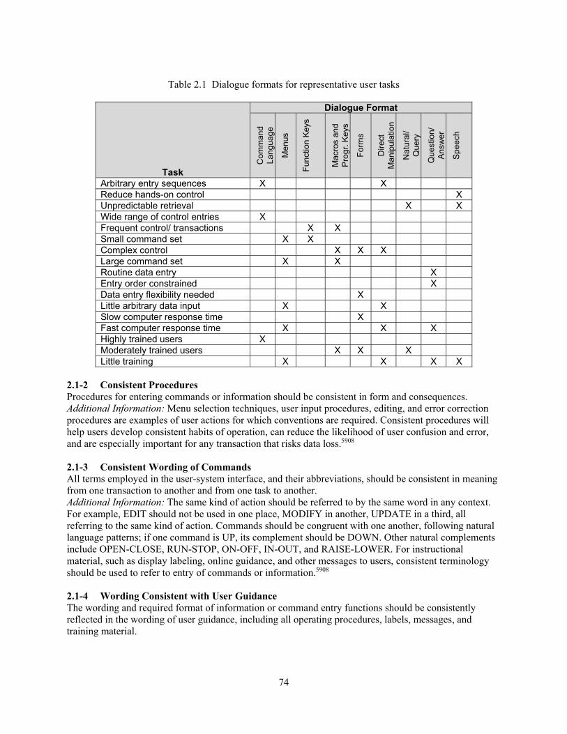
74
Table 2.1 Dialogue formats for representative user tasks
Task
Dialogue Format
Com
man
d La
ngua
ge
Men
us
Func
tion
Keys
Mac
ros
and
Prog
r. Ke
ys
Form
s
Dire
ct
Man
ipul
atio
n
Nat
ural
/ Q
uery
Que
stio
n/
Answ
er
Spee
ch
Arbitrary entry sequences X X Reduce hands-on control X Unpredictable retrieval X X Wide range of control entries X Frequent control/ transactions X X Small command set X X Complex control X X X Large command set X X Routine data entry X Entry order constrained X Data entry flexibility needed X Little arbitrary data input X X Slow computer response time X Fast computer response time X X X Highly trained users X Moderately trained users X X X Little training X X X X
2.1-2 Consistent Procedures Procedures for entering commands or information should be consistent in form and consequences. Additional Information: Menu selection techniques, user input procedures, editing, and error correction procedures are examples of user actions for which conventions are required. Consistent procedures will help users develop consistent habits of operation, can reduce the likelihood of user confusion and error, and are especially important for any transaction that risks data loss.5908 2.1-3 Consistent Wording of Commands All terms employed in the user-system interface, and their abbreviations, should be consistent in meaning from one transaction to another and from one task to another. Additional Information: The same kind of action should be referred to by the same word in any context. For example, EDIT should not be used in one place, MODIFY in another, UPDATE in a third, all referring to the same kind of action. Commands should be congruent with one another, following natural language patterns; if one command is UP, its complement should be DOWN. Other natural complements include OPEN-CLOSE, RUN-STOP, ON-OFF, IN-OUT, and RAISE-LOWER. For instructional material, such as display labeling, online guidance, and other messages to users, consistent terminology should be used to refer to entry of commands or information.5908 2.1-4 Wording Consistent with User Guidance The wording and required format of information or command entry functions should be consistently reflected in the wording of user guidance, including all operating procedures, labels, messages, and training material.

75
Additional Information: Thus, when the computer displays a file name, that name should be shown in a format that would be acceptable if the name were included in a command entry. For example, if a user must complete a control form to specify printer settings, the words used as labels on that form should also be used in any error messages and HELP displays that may guide that process.5908 2.1-5 Minimal Demands on the User Entry of information or commands should not require the user to remember special codes or sequences or to perform translations or conversions. Additional Information: Command names should specifically describe the functions being implemented and should reflect the vocabulary and syntax of the user’s operational language. The user should not have to transform units when entering data. For example, user entries should be in the same units that are used in control room displays and procedures; the user should not be required to convert from gallons per minute to gallons per hour.5908, 0700 2.1-6 Minimal User Actions User input actions should be simple, particularly for realtime tasks requiring fast user response. Additional Information: The user interface should permit completion of a task with the minimum number of actions. For example, a user should be able to print a display by simple request, without having to take a series of other actions first, such as calling for the display to be filed, specifying a file name, then calling for a print of that named file. For long, multipage displays, it should be possible to request a particular page directly, without having to take repetitive NEXT PAGE or PREV PAGE actions. This guidance does not apply to potentially destructive functions; extra user actions required to invoke such functions serve to make them less likely to be inadvertently activated.5908
2.1-7 Unnecessary Entry of Information A user should not be required to reenter information already available to the system. Additional Information: A user should need to enter any particular information only once, and the computer should access that information, if needed thereafter for the same task or for different tasks. Reentry of data requires unnecessary effort on the part of users and increases the possibility of entry errors. The computer should automatically access or compute information that can be derived from existing computer records.5908 2.1-8 Availability of Information Users should have available the information necessary to accomplish a specific entry (e.g., labels, annotations, prompts, or options lists) when that transaction action is appropriate. Additional Information: Required annotation will vary with the application. Some annotation may be so commonly needed that it should be continuously displayed (e.g., document name, page number, and indication of control mode (if any)). Other annotation might be displayed only by user request, such as document status (date last changed or last printed), which might be displayed in an optional window overlay, and format control characters, which might be visible in an optional display mode. For example, the user might wish to see format control characters, such as tab and margin settings.5908 2.1-9 Logical Transaction Sequences An information entry sequence should be designed so that its organization reflects the user’s view of the task and should provide all control options that may be required. Additional Information: A logical unit to the user is not necessarily the same as a logical unit of the computer software that mediates the transaction sequence. It might be, for example, that a user should enter ten items of data in a single transaction, because those data all come from one particular paper form, even though the computer will use five of those items for one purpose and five items for another in its subsequent internal processing.5908

76
2.1-10 Flexible User Entry The user should have flexible means of entering information or commands to accomplish necessary transactions and obtain guidance as needed in connection with any transaction. Additional Information: The user should be able to go forward or back at will when scanning a multipage display. A user-interface design that permits only forward steps is deficient because the user must cycle through an entire display series to reach a previous page.5908 2.1-11 Control by Explicit User Action Users should be allowed to control the processing of information or commands by explicit action. Additional Information: The processing of an entry or the cancellation of an ongoing process should not occur as a side effect of some other action. For example, when a user is keying an extended data entry, the computer should not interrupt the user to require immediate correction of any entry error but instead should wait for the user’s ENTER action. Also, when a user is composing a command to accomplish some transaction, the computer should not interrupt the user by responding as soon as it recognizes a partial entry but instead should wait for the user’s ENTER action. In automated process control applications, emergency conditions may take precedence over current user transactions, and a computer-generated warning might interrupt user actions. In routine, repetitive data entry transactions, successful completion of one entry may lead automatically to initiation of the next. Computer detection of problems with current user entries can usually be negotiated at the end of a transaction, before it is implemented. Nondisruptive alarms or advisory messages can be displayed to report computer monitoring of external events so that the user can choose when to respond to them.5908 2.1-12 Compatibility with User Expectations The results of any entry should be compatible with user expectations, so that the system changes in a “natural” way in response to user actions. Additional Information: The result of an entry should be consistent with the user’s view of the system. For example, a control entry of NEXT PAGE should show the next frame of a current display and should not jump off to some other internally defined “page” in the computer’s database. When the completion of a control entry is indicated by a special function key, that key should be labeled ENTER (or some functionally equivalent word) and should result in computer acknowledgment of the entry.5908 2.1-13 Feedback for User Entries The computer should acknowledge every entry immediately. Additional Information: For every entry action by the user, there should be some obvious reaction from the computer. The absence of computer response is not an acceptable means of indicating that an entry is being processed. “Immediately,” as used in this guideline, must be interpreted in relation to the response time requirements of different dialogue types. For example, execution of a requested transaction might produce an immediately apparent result, as when a user requests NEXT PAGE and the next page is displayed. A message might indicate completion of a transaction, as when a user requests a printout at a remote facility and the computer displays a confirming message “RAD WASTE file has been sent to printer”; or a message might indicate that execution is in progress or deferred, as when a user enters data and the computer displays an interim message “RAD WASTE file is being updated.” A message might indicate that the control entry requires correction or confirmation, as when a user requests a file display and the computer displays an error message “RAD WASTE file not recognized.” In a menu selection context, it may suffice simply to highlight the selected option label (e.g., by brightening or inverse video) when that would provide an unambiguous acknowledgment.5908 2.1-14 Periodic Feedback When system functioning requires the user to stand by, periodic feedback should be provided to indicate normal system operation. Additional Information: In addition to the indication that the system has received the menu-based

77
command, feedback about completion of the command should be communicated. Completion of the action commanded by the menu item will be sufficient feedback, provided that the action has a result that is visible to the user. However, if the completion of the menu item has no visible result, the additional feedback that the command was completed should be communicated by a message in the Message Area.5908 2.1-15 Indicating Completion of Processing When processing in response to an entry is lengthy, the user should be given some positive indication of subsequent completion. Additional Information: Completion of the action commanded by the menu item will be sufficient feedback, provided that the action has a result that is visible to the user. However, if the completion of the menu item has no visible result, a message should communicate the additional feedback that the command was completed. If a user is currently involved in some new transaction, then completion of processing for a prior transaction should be indicated by the nondisruptive display of an appropriate advisory message. If the outcome of a completed transaction implies the need for further user action, that should be indicated to the user.5908 2.1-16 Indicating Control Lockout If entries must be delayed pending computer processing of prior entries, the delay should be indicated to the user. Additional Information: A change in the appearance of the cursor, accompanied by an auditory signal, could signal a processing delay that results in control lockout. In some applications, it may be desirable to ensure that the keyboard and other control devices are automatically locked until the user can begin a new transaction. This would be true when processing the current transaction will affect the results of subsequent user actions. In other applications, it may be possible to permit users to continue work while previous transactions are still being processed. Deletion or change of a displayed cursor in itself may not be a sufficient indicator of keyboard lockout. Auditory signals will be particularly helpful to a user who may not look at the display when making entries. Following control lockout, the user should receive an indication of computer readiness to accept further entries.5908 2.1-17 Interrupt To End Control Lockout In situations where control lockout does occur, an auxiliary means of control entry should be provided, such as a special function key, to abort a transaction causing extended lockout. Additional Information: Such an interrupt capability, acting like an UNDO command, will be especially helpful if a user recognizes that an error has been made and wants to stop an unneeded transaction.5908 2.1-18 Entry via Principal Display When data entry is a significant part of a user’s task, entered data should appear on the user’s main display. Additional Information: When the main display is basically formatted for other purposes, such as a graphic display for process control, a separate window or area on the display may have to be reserved for data entry.5908 2.1-19 Entry of Corrections The entry of corrections should require the same explicit ENTER action as used for the original entry.5908 2.1-20 Editing Capabilities during Text Entry Users should be able to perform simple editing during text entry without having to invoke a separate edit mode. Additional Information: While entering text, users should have some capability for text selection (by cursor movement) and deletion (e.g., by use of destructive backspace). The intent of this guideline is not

78
to endorse modeless over moded text editors. In fact, when experienced users perform editing tasks, a moded editor may offer some advantages. However, if a moded editor is provided, users should be able to do some simple editing, such as correcting typographical errors and making simple word changes, without having to invoke that editor. When users compose text on line, consider providing a modeless editor rather than a moded editor. Modeless editors offer some advantages for text composition, when users will frequently alternate between text entry and editing.5908 2.1-21 Entries Distinct from Text If entries are made by keying onto the display, such as by keyed menu selections or commands, they should be distinguishable from displayed text. Additional Information: The user should not be able to enter controls as text or vice versa. Errors can be avoided by having keyed entries made only in a reserved window in the display, or by using function keys rather than text entry.5908 2.1-22 Variable-Length Data Area Users should not have to remove unused underscores or otherwise enter keystrokes for each position within a variable-length entry area.5908 2.1-23 Optional Versus Required Entry Optional versus required data entries within fields on input forms should be distinct.5908 2.1-24 Display of User Annotations Annotations added by users to displayed text should be distinguishable from the text itself. Additional Information: This recommendation refers to additions such as marginal notes on printed displays. Other annotation such as format control characters might be shown in a special display mode where text has been expanded to permit annotation between lines. For example, continuous annotation might be displayed in the top or bottom lines of a page, separated from the text by blank lines; optional annotation might be displayed in window overlays.5908 2.1-25 Flexible Interaction Design When information or command entry requirements may change, the user (or a system administrator) should have some means to make necessary changes to available functions. Additional Information: Entry functions that may need to be changed include the types of dialogue that are provided, procedures for transaction selection and interrupt, methods for context definition and error management, and alarm control.5908 2.1-26 Guidance Information Users should be able to request guidance information about requirements for information on command entry (e.g., syntax, parameters, and options).5908 2.1-27 Entry Procedures Matched to User Skill The means of entering information or commands should be compatible with user skills, permitting simple step-by-step actions by beginners but permitting more complex entries by experienced users. Additional Information: Most systems will have users with varying levels of experience. Any particular user may become more expert with increasing experience, or perhaps less expert after a long period of disuse. Accommodating users of varying expertise requires a mixture of different dialogue types, with some means for smooth transition from one mode of dialogue to another. For instance, as users come to learn menu codes, they might be allowed to enter those codes without necessarily displaying a menu (i.e., those codes might also serve as commands).5908

79
2.1-28 Stacked Entries Users should be allowed to key a sequence of commands or option codes as a single “stacked” entry. Additional Information: In particular, users should be allowed to enter stacked entries from any menu so that an experienced user can make any specific entry without having to view subsequent menus. Entry stacking may be helpful when a user is being prompted to enter a series of parameter values and knows what several succeeding prompts will request and what values to enter. Entry stacking will permit a transition from simple step-by-step entry by novice users, as in menu selection and question-and-answer dialogues, to the entry of extended command-language statements by experienced users. Entry stacking is especially helpful in time-shared systems where the computer response to any user entry may be slow.5908 2.1-29 Consistent Order in Entry Stacking For control entry stacking, entries should be required to be made in the same order as they would normally be made in a succession of separate control entry actions.5908 2.1-30 Abbreviation in Entry Stacking For control entry stacking, command names, their abbreviations, or option codes should be accepted just as if those control entries had been made separately. Additional Information: In some applications, it might prove helpful if the computer were to display its interpretation of a stacked entry for user review and confirmation.5908 2.1-31 Minimal Punctuation of Stacked Entries Users should be allowed to stack control entries without any punctuation other than spaces between words or option codes.5908 2.1-32 Standard Delimiter in Entry Stacking If punctuation other than spaces is needed to separate entries in a stacked control entry, a single standard symbol should be used for that purpose. Additional Information: A slash (/) is often used to separate stacked entries. Whatever symbol is adopted as a delimiter for control entries should preferably be the same as any delimiter that might be used when making data entries. Note that, even when a standard symbol is consistently used to punctuate stacked entries, entry will be slower and less accurate than if only spaces are used for punctuation.5908 2.1-33 Distinctive Display of Control Information All displays should be designed so that features relevant to user entries are distinctive in position, format, or both. Additional Information: Relevant features include displayed options, command entry areas, prompts, advisory messages, and other displayed items (such as titles and time signals) when changes signal the results of user entries.5908 2.1-34 Displayed Context If the consequences of a user entry will differ depending upon context established by a prior action, then the user should receive some continuous indication of current context for reference. Additional Information: The user should not have to query the system to determine the current mode. For example, if activating a DELETE key establishes a mode, so that the subsequent selection of a PAGE key will erase a page of data rather than simply advancing to display the next page, then the user should receive some indication of that established DELETE mode.5908 2.1-35 Consistent Display of Context Information Information displayed to provide context for user entries should be distinctive in location and format and consistently displayed from one transaction to the next.

80
Additional Information: The system should indicate the current position within a sequence.5908 2.1-36 Record of Prior Entries Users should be permitted to request a summary of prior entries to help determine present status and should be allowed to review the parameters currently in effect. Additional Information: Summarizing prior entries will be particularly helpful in tasks where the sequence of user actions is variable, where a user must know what was done to decide what to do next. Summarizing prior entries may not be needed for routine transactions if each step identifies its predecessors explicitly, although even in those circumstances, a user may be distracted and at least momentarily become confused. A capability for parameter review may likewise be helpful, even when a user selects all parameters personally.5908 2.1-37 Standard Display Area for Command Entry Every display should include a command entry area in a consistent location, preferably at the bottom. Additional Information: Adjacent to the command entry area, there should be a display window reserved for prompting entries, for recapitulating command sequences (with scrolling to permit extended review), and for mediating question-and-answer dialogue sequences (i.e., prompts and responses to prompts).5908 2.1-38 General List of Options A general list of basic options should be provided and always be available to serve as a “home base” or consistent starting point for user input. Additional Information: Return to this starting point can be accomplished by an OPTIONS function key, by an explicit option on every display, or by a generally available implicit option. Such a capability may be helpful even when all dialogue is user initiated. It might be the general menu for a menu selection dialogue, or it might be a standard starting point for composing command entries. However, a user should not be required to return to a display of general options to make an entry. If a user remembers option codes or commands, ideally those entries could be made from any point in a transaction sequence.5908 2.1-39 Displaying Option Codes When users must select options by code entry, the code associated with each option should be displayed in a consistent and distinctive manner. Additional Information: In many applications, an equal sign is used to designate option codes, such as N = Next page and P = Previous page.5908 2.1-40 Organization and Labeling of Listed Options The general options list should show control entry options grouped, labeled, and ordered in terms of their logical function, frequency, and criticality of use, following the general guidelines for menu design. Additional Information: For systems in which selection is made by a cursor, formats should be organized to minimize the need to reposition cursors.5908, 0700 2.1-41 Indicating Available Control Options Users should have a list of the control options that are specifically appropriate for any transaction. Additional Information: Transaction-specific options might be listed in the working display if there is space for them. Otherwise, they might be displayed in an overlay window by user request. Control options that are available for almost any transaction should be treated as implicit options, which need not be included in a list of transaction-specific options, unless they are particularly appropriate to the current transaction.5908 2.1-42 Only Available Options Offered Only control options that are actually available for the current transaction should be offered to users. Additional Information: If certain options are not yet implemented, as during system development, or are
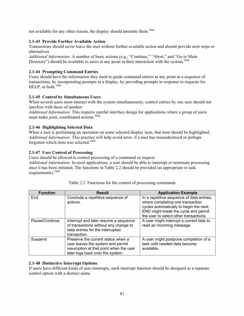
81
not available for any other reason, the display should annotate them.5908 2.1-43 Provide Further Available Action Transactions should never leave the user without further available action and should provide next steps or alternatives. Additional Information: A number of basic actions (e.g., “Continue,” “Abort,” and “Go to Main Directory”) should be available to users at any point in their interaction with the system.5908 2.1-44 Prompting Command Entries Users should have the information they need to guide command entries at any point in a sequence of transactions, by incorporating prompts in a display, by providing prompts in response to requests for HELP, or both.5908 2.1-45 Control by Simultaneous Users When several users must interact with the system simultaneously, control entries by one user should not interfere with those of another. Additional Information: This requires careful interface design for applications where a group of users must make joint, coordinated actions.5908 2.1-46 Highlighting Selected Data When a user is performing an operation on some selected display item, that item should be highlighted. Additional Information: This practice will help avoid error, if a user has misunderstood or perhaps forgotten which item was selected.5908 2.1-47 User Control of Processing Users should be allowed to control processing of a command or request. Additional Information: In most applications, a user should be able to interrupt or terminate processing once it has been initiated. The functions in Table 2.2 should be provided (as appropriate to task requirements).5908
Table 2.2 Functions for the control of processing commands
Function Result Application Example End Conclude a repetitive sequence of
actions. In a repetitive sequence of data entries, where completing one transaction cycles automatically to begin the next, END might break the cycle and permit the user to select other transactions.
Pause/Continue Interrupt and later resume a sequence of transactions without any change to data entries for the interrupted transaction.
A user might interrupt a current task to read an incoming message.
Suspend Preserve the current status when a user leaves the system and permit resumption at that point when the user later logs back onto the system.
A user might postpone completion of a task until needed data become available.
2.1-48 Distinctive Interrupt Options If users have different kinds of user interrupts, each interrupt function should be designed as a separate control option with a distinct name.

82
Additional Information: The means of invoking interrupt functions should be clear to the user. For example, it is undesirable to have a single INTERRUPT key that has different effects, depending upon whether it is pushed once or twice. Users would be confused by such an expedient and uncertain about what action has been taken and its consequences.5908 2.1-49 User Transaction Interrupts User interrupts and aborts should not modify or remove stored or entered data.5908
2.1-50 User Control of Entry Users should be allowed to control the pace and sequence of their entry of information or commands. Additional Information: The functions in Table 2.3 should be provided (as appropriate to the task).5908
Table 2.3 Functions for the control of entering information
Function Result Application Example Cancel Erase any changes just made by
the user and restore the current display to its previous version.
Correct erroneous input before actually entering the information in a data file.
Back Return to the display for the last previous transaction.
In a sequence of related data entries, on several display frames, return to the previous frame, where data items could then be erased or could be edited individually.
Review Return to the first display in a defined transaction sequence; permit the user to review a sequence of entries and make necessary changes.
In a sequence of related data entries, on several display frames, return to the first frame, from which data could be reviewed and edited as needed throughout the sequence of frames.
Restart Cancel any entries that have been made in a series of entries and return to the beginning of the sequence.
In a sequence of related data entries on a form-filling display, erase all data entries and return to the first field on the form.
2.1-51 User-Specified Transaction Timing When appropriate to task requirements, users should be allowed to specify the timing of transactions. Additional Information: Users should be able to specify when a requested transaction should start or be completed, or to schedule periodic transactions. In many applications, users will wish specified transactions to be performed as quickly as possible. In some applications, however, users may have good reasons to delay initiation (or completion) of transactions. For example, a user might wish to specify that a requested data analysis routine be deferred until some later time, to ensure that interim updates to the data will be taken into account.5908
2.1-52 Indicating PAUSE/SUSPEND Status If PAUSE or SUSPEND options are provided, some indication of the status should be displayed whenever a user selects such an option. Additional Information: If appropriate (i.e., for a paused transaction), the user should receive an indication of the action that will permit resumption of the interrupted transaction.5908 2.1-53 Consistent CONTINUE Option At any step in a defined transaction sequence, if there is only a single appropriate next step, then a consistent control option to continue to the next transaction should be provided.

83
Additional Information: CONTINUE or NEXT or STEP are all suitable names for this option. If data entry is involved, then users should be required to take an explicit ENTER action to signal data entry, rather than simply selecting CONTINUE.5908 2.1-54 Data Manipulation The user should be able to manipulate information without concern for internal storage and retrieval mechanisms of the system. Additional Information: The system should contain sufficient memory to accommodate the user’s requirements.5908 2.1-55 Default Values When likely default values can be defined for the information to be entered in a particular task, those default values should be offered to speed entry. Additional Information: When defaults are defined that may vary from one transaction to another, users should be informed of the current default logic (for example, “Press ENTER to see more options”). If a consistent default is adopted throughout interface design, that default need not be explicitly indicated for each individual transaction. Here the phrase “null control entry” refers to pressing an ENTER key without first keying a command or option code (and without any accompanying data). It does not refer to defaults for optional parameters that might accompany a valid control entry, whose values might be displayed only by user request. It is not necessary that any defaults be defined for null control entries. In such cases, the computer might simply respond “ENTER alone is not recognized here.”5908 2.1-56 Display of Default Values At the start of an input transaction, currently defined default values should be displayed in their appropriate data fields. Additional Information: It may be helpful to mark default values in some way to distinguish them from new data entries.5908 2.1-57 Easy Confirmation To Enter Default Values Users should have some simple means to confirm acceptance of a displayed default value. Additional Information: Similar techniques (e.g., tabbing past the default field) should be used when a user must review the accuracy of previously entered data.5908 2.1-58 User Definition of Default Values Users should be permitted to define, change, or remove default values for any input field. Additional Information: Users should be allowed to replace any default value with a different entry, without thereby changing the default definition for subsequent transactions. The direct replacement of a default value in a data field with a new value should not change the definition of the default value.5908, 6546 2.1-59 Indicating Control Defaults When keyed command or option code entries are used and a default is defined for a null control entry, the user should receive an indication of the default.5908 2.1-60 Single Method for Input Input transactions and associated displays should be designed so that a user can stay with one method of entry and not have to shift to another. Additional Information: For example, shifts from mouse to keyboard entry and then back again should be minimized. Forcing users to shift from one keyboard to another, or move from one workstation to another, to accomplish different input tasks should also be avoided.5908
84
2.1-61 Uppercase and Lowercase Equivalent For interpreting user-composed control entries, uppercase and lowercase letters should be treated as equivalent. Additional Information: Because users find it difficult to remember whether uppercase or lowercase letters are required, the interface design should not try to make such a distinction.5908 2.1-62 Justification of Entries Unless otherwise required by processing or display requirements, alphabetic input should be left justified, and numeric input should be right justified for integer data or decimal point justified for decimal data. Additional Information: Optional entry or omission of a decimal point at the end of an integer should be allowed as equivalent alternatives.5908 2.1-63 Automatic Justification of Entries Automatic justification of tabular data entries should be provided. Additional Information: A user should not have to enter blanks or other extraneous formatting characters to achieve proper justification. For example, if a user enters “56” in a field four characters long, the system should not interpret “56 __ __” as “5600.” For general numeric data, optional entry or omission of leading zeros should be allowed as equivalent alternatives. If a user enters “56” in a field that is four characters long, the system should recognize that entry rather than requiring an entry of “0056.” Special cases may represent exceptions to this rule, such as the entry of serial numbers or other numeric identifiers.5908 2.1-64 Maintaining Significant Zeros When a user must enter numeric values that will later be displayed, all significant zeros should be maintained. Additional Information: Zeros should not be arbitrarily removed after a decimal point if they affect the meaning of the number in terms of significant digits.5908 2.1-65 Significance of Numeric Values Numeric values should be displayed to the level of significance required of the task. 5908 2.1-66 Overwriting Characters Data entry by overwriting a set of characters within a field should be avoided. Additional Information: If a user chooses to alter the contents of a field, the displayed previously existing entry (e.g., a default value or label) should be cleared from the input field.5908 2.1-67 Consistent Location of Interface Management Controls Controls used for interface management tasks should have consistent locations. Additional Information: Interface management controls include user interfaces for selecting displays and navigating within displays. Examples include command fields, function buttons, and scroll bars. Consistent locations are one way to uniquely identify interface management controls to support users in identifying and accessing them.6546 2.1-68 Location of Display Page Navigation Controls Controls for navigating within a display page should be separate from the main body of the display screen. Additional Information: Examples of controls for navigating within displays include command fields, function buttons, and scroll bars.6546
85
2.1-69 Setup of Computer-Based Systems Preset and automated setup features should ensure that users do not have to perform these functions while operating the plant. Additional Information: Preset features are ready to use without a separate setup operation. Automated setup features are performed by the system rather than by personnel. The demands associated with setting up a computer-based system before it is used can distract personnel from primary tasks. The use of preset and automated setup features should minimize system setup demands that may interfere with primary tasks.6546 2.1-70 Reminders for Interrupted Tasks The HSI should provide visual or auditory reminders, or both, for interrupted tasks.6546 2.1-71 Access to Suspended Tasks The HSI should provide simple mechanisms for retrieving displays and controls for tasks that have been suspended. Additional Information: Extensive effort should not be required to either retrieve the display or reconfigure the display so that work may resume on a suspended task.6546 2.1-72 Entry of Data Separators and Delimiters The user should not be required to enter data separators or delimiters, such as dashes and slashes. Additional Information: The entry of data separators and delimiters can be time consuming and error prone.6546 2.1-73 Entry of Measurement Units The user should not be required to enter units of measure. Additional Information: The entry of dimensional units (e.g., “gpm”) can be time consuming and error prone.6546 2.1-74 Minimize Cursor Travel Travel distance for cursors across and between display pages and windows on a display screen should be minimized. Additional Information: Unnecessary cursor movement can increase information access cost and divert mental resources from more important tasks by requiring the user’s attention and time for execution.6546 2.1-75 Default Configuration for Decluttering Displays that can provide decluttering capabilities should also allow the user to rapidly return the display to its original configuration.6546 2.2 User Input Formats 2.2.1 Command Language 2.2.1-1 Layered Command Language A command language should be designed so that its functions are organized in groups (or “layers”) for ease in learning and use. Additional Information: A user should be able to display the next of a set of received messages with some simple command such as READ NEXT, although a complete command to retrieve any message might include potential specification of which message, from which message list, in which format, and to which output device. The fundamental layer of the language should be the easiest, allowing use of the system by people with little training or limited needs, or both. Successive layers of the command language can then increase in complexity for users with greater skills. In effect, simple versions of commands can be
86
recognized by defaulting all the optional parameters. Control forms might be used to display default options for complicated commands.5908 2.2.1-2 General List of Commands The user should have a general list of basic commands, with appropriate command format guidance.5908 2.2.1-3 Distinctive Meaning for Commands Similar words in a command language should be distinctive and emphasize significant differences in function. Additional Information: In general, commands should not have semantically similar names, such as SUM and COUNT, or ERASE and DELETE, or QUIT and EXIT.5908 2.2.1-4 Distinctive Spelling for Commands Words and abbreviations in a command language should have distinctive spellings, so that simple spelling errors will be recognized as such rather than invoking a different command. Additional Information: If one command name is DELETE, abbreviated DEL, then another command should not be named DELIVER, with an abbreviation of DELR. Instead, ERASE could be substituted for DELETE, or SEND for DELIVER. When a system has only a few commands, all those commands should be distinctive. When a system has many commands, it may not be possible to ensure that each is distinctive. In that case, it is important to ensure that any commands that are destructive or time consuming are made distinctive.5908 2.2.1-5 Abbreviation of Commands Users should be allowed to abbreviate commands. Additional Information: Entries should not exceed seven characters. Users should be required to enter only as many characters as needed to uniquely identify the desired command. For example, if a “P” uniquely identifies a print command (i.e., no other commands start with “P”), then a user should be able to enter PRINT, or PR, or P to initiate printing.5908, 0700 2.2.1-6 Recognizing Command Synonyms The computer should recognize a variety of synonyms for each word defined in the command language. Additional Information: The synonyms that are likely to be used can be determined by analysis of error records in prototype testing. This flexibility can allow infrequent users to interact with a system more efficiently. The user may be required to verify commands recognized in this way. It may be useful, for example, for the system to accept “UP” as well as “RAISE.”5908 2.2.1-7 Interpreting Misspelled Commands Where the set of potential command entries is well defined, the computer should recognize and execute common misspellings of commands rather than requiring reentry. Additional Information: Misspelled command entries should be tolerated within the limits of computer recognition. The user may be required to verify commands recognized in this way. The computer can interrogate a user as necessary to resolve ambiguous entries.5908 2.2.1-8 Recognizing Alternative Syntax The computer should recognize probable alternative forms of command syntax. Additional Information: Users might be allowed to use different punctuation or to list command modifiers in different orders. For example, the computer might accept alternative methods of specifying a request, such as “SG3 LVL,” “LVL SG3,” or “LVL/SG3.”5908

87
2.2.1-9 User-Assigned Command Names A command language should have flexibility to permit a user to assign personal names to frequently used commands. Additional Information: Frequently used commands should be easy for a user to enter. For users who must move back and forth between different systems with differently defined command languages, some flexibility in command naming will permit those users to establish their own consistent terminology. Where this capability exists, several cautions should be observed. Before users can be allowed to adopt their own assigned command names, the computer must check those names to prevent duplication. In addition, there is a potential risk of confusion if users forget what names they have specified for commands and data files. The computer should maintain a current index of command and file names for online user reference.5908 2.2.1-10 User-Requested Prompts Users should be allowed to request computer-generated prompts as necessary to determine required parameters in a command entry or to determine available options for an appropriate next command. Additional Information: Users might request prompting by using a HELP function key or perhaps simply keying a question mark in the command entry area.5908 2.2.1-11 Minimal Punctuation Users should be allowed to enter commands without any punctuation other than the spaces between words. Additional Information: Command entry will be faster and more accurate when spaces are used rather than any other kind of punctuation.5908 2.2.1-12 Ignoring Blanks in Command Entry Single and multiple blanks between words should be treated as equivalent when processing command entries. Additional Information: Because people cannot readily distinguish one blank space from several, the computer should not impose such a distinction.5908 2.2.1-13 Standard Delimiter If command punctuation other than spaces is required, a single standard delimiter symbol should be used for that purpose. Additional Information: Command punctuation other than spaces may be required as a delimiter to distinguish optional parameters or to separate entries in a stacked command. For example, a slash (/) might be a good choice. Whatever symbol is adopted as a delimiter for command entries should preferably be the same as any delimiter that might be used when making data entries. Note, however, that even if some single delimiter is specified for consistent use in command punctuation, command entry will be slower and less accurate than if no delimiter at all were required.5908 2.2.1-14 Illustrations in Guidance Information Where possible, guidance information should be accompanied with graphic illustrations of command content and syntax.5908 2.2.1-15 User-Defined Abbreviations and Aliases Experienced users should be able to define abbreviations or aliases for commands. Additional Information: Abbreviations and aliases can reduce the time required to enter commands.6546 2.2.1-16 Aiding Command Recall The system should provide features that support users in recalling command names. Additional Information: Some of the features that can provide such support include the following:

88
• User-requested prompts—These are prompts invoked by the user (e.g., through online help or
function keys) that may indicate the allowable parameters of a command entry or available command options.
• User-assigned command names—Some display systems allow the users to assign names to
commands. This capability may support recall, for example, when users must use more than one display system having differently defined commands. By providing some flexibility in renaming the commands, users can enhance the consistency between dialogues.
• Layering of commands—Command dialogues may be designed so that functions are organized in
related groups or layers.6546
2.2.1-17 Accepting Minor Variations The system should tolerate minor variations in input commands for interface management functions. Additional Information: Examples of this capability include recognition of command synonyms, interpretation of slightly misspelled commands, ability to ignore unnecessary blank spaces, and recognition of simplified command formats (i.e., minimal use of punctuation and delimiters).6546 2.2.2 Menus 2.2.2.1 General 2.2.2.1-1 Explicit Option Display When entries for any particular transaction will be selected from a small set of options, a menu added to the working display should show those options, so the user is not required to remember them or to access a separate menu display. Additional Information: A complete display of control options will sometimes leave little room to display data. If an extensive menu must be added to a working data display, that menu should be in a separate window that can temporarily overlay displayed data by user request but can then be closed again by further user action.5908 2.2.2.1-2 Consistent Display of Menu Options When menus are provided in different displays, they should be designed so that option lists are consistent in wording and ordering. Additional Information: If menu options are variable, common elements should maintain their physical relationship to other recurring elements. For example, if the SEND command appears above EXIT in one menu, it should not appear below EXIT in another menu, or be denoted differently (e.g., by the word SUBMIT).5908 2.2.2.1-3 Consistent Location for Menus Menus should be displayed in consistent screen locations for all modes, transactions, and sequences. Additional Information: This applies to popup, pulldown, and windowed menus and to menu bars.5908 2.2.2.1-4 Consistent Entry Prompt When permanent menus are used, the input prompt should have one standard design across all tasks. Additional Information: A consistent prompt unambiguously indicates the need for user input. For example, “ENTER CHOICE: __.”5908 2.2.2.1-5 Permanent Menus Minimized The use of permanent menus should be minimized.

89
Additional Information: Permanent menus require dedicated display space and more paging activity (because the application must return the user to the main menu page at every task change). However, permanent menus might be used when (1) it is beneficial to examine every option in detail, (2) the amount of text in each menu item is large, or (3) there is no pointing device available.5908 2.2.2.1-6 Activation of Pulldown and Popup Menus Pulldown and popup menus should be activated only by a specific user action that requests the display of the menu. Additional Information: Menus should not appear simply because the cursor has passed over the menu title.5908 2.2.2.1-7 User-Requested Menus: Pulldowns and Popups User-requested menus should be used whenever possible. Additional Information: Among the types of user-requested menus, pulldown menus provide two advantages over popup menus: (1) the menu bar serves as a useful mnemonic aid, showing the user the command categories available in the menu, and (2) gaining visual access to the menu items within a category, selecting the item, and removing the menu can be accomplished with a minimal number of actions. The primary advantage of a popup menu over a pulldown menu is that, depending on the specific implementations, the user may have immediate access to the menu at the screen location of the selection action. The ideal user-requested menu design would provide the user with a reminder of the menu categories and allow the user to select an item with few actions and little movement of a cursor on the screen.5908 2.2.2.1-8 Hiding Menus after a Command Is Carried Out After the selection of pulldown or popup menu items, the menu should revert to its hidden state as the selected command is carried out.5908 2.2.2.1-9 Programmable Keys If menu items are selectable by activating programmable function keys, the arrangement of the menu list should be compatible with the arrangement of the keys to the greatest degree possible.5908 2.2.2.1-10 Explanatory Title for Menu An explanatory title should be provided for each menu that reflects the nature of the choice to be made. Additional Information: EXAMPLE: (Good) Organizational Role: r = Responsible, a = Assigned, p = Performing. (Bad) Select: r = Responsible, a = Assigned p = Performing. When instructions to the user accompany a list of options, the instructions should precede presentation of the list.5908, 0700 2.2.2.1-11 Complete Display of Menu Options A menu should be designed to display all options appropriate to any particular transaction. Additional Information: A familiar set of general control options (i.e., options that are always implicitly available) may be omitted from individual displays. Such general options might be selected by requesting a general menu or perhaps by function key or command entry.5908 2.2.2.1-12 Option Display Dependent on Context Menus should display as selectable only those options that are actually available in the current context. Additional Information: If a user selects a displayed option and is then told that option is not actually available, an undesirable element of unpredictability has been introduced into the interface design. Users may become uncertain and confused about command entry. There should be some indication of which options are currently available (see Guideline 2.2.2.5-8).5908, 0700

90
2.2.2.1-13 Function of Menu Should Be Evident Menus should be designed so that the function of the menu is evident to the user.5908 2.2.2.1-14 Menus Distinct from Other Displayed Information If menu options are included in a display that is also intended for data review or data entry, or both, the menu options should be distinct from other displayed information. Additional Information: Menu options should be located consistently in the display and incorporate some consistent distinguishing feature to indicate their special function, perhaps beginning with a special symbol such as a plus sign (+NEXT or +BACK). “Embedded menus,” in which various items within a working display are highlighted in some way to indicate that they can be selected to obtain further information, may also be used.5908 2.2.2.1-15 Breadth and Depth of Menu Items Menus should have a limited number of items in breadth and in depth. Additional Information: Moderate menu breadth (e.g., number of menus in a menu hierarchy, number of menu categories in a menu bar, or number of popup menus) and depth (e.g., number of items per menu or, in menu bars, per menu category) should be facilitated by the use of a hierarchic menu structure whereby the selection of items from one menu (the parent) activates a second menu (the child) with further options. The parent menu should remain visible during the selection of the child menu. The number of levels in the hierarchy should be limited (for example, to no more than three).5908 2.2.2.1-16 Number of Options Each menu option list should have four to eight options. Additional Information: Menus with only two options should be avoided. “Menus” with only one item should not be used.5908 2.2.2.1-17 Equivalent Keyboard Commands Equivalent keyboard commands should be displayed as part of the menu option label.5908 2.2.2.1-18 Continuous Presentation of Menu If continual or frequent reference to menu options is necessary, then the menu should be permanently presented in an area of the screen where it will not obscure other data. Additional Information: If only occasional reference to menu options is necessary, the menu may be presented upon demand.6546 2.2.2.1-19 Providing Default Options If one option on a menu is selected more often than the others, then it should be highlighted. Additional Information: Search and selection is enhanced by highlighting and preselecting the default option. For example, the cursor may be automatically positioned over the default option, or the text string for the default option may automatically appear in the input field.6546 2.2.2.1-20 Option Previews Where discrimination among options may be difficult for users, menus can provide a preview of options. Additional Information: This will support the user in determining which of the current options to select.6546 2.2.2.1-21 Visual Grouping of Menu Options If meaningful categories cannot be developed for menu options, then visual groups should be created for long menus.

91
Additional Information: Noncategorized menus may be divided into arbitrary visual groupings using space or lines. The groups should be as equal in size as possible. Each group should consist of four to seven options. The use of visual grouping can facilitate visual search.6546 2.2.2.1-22 Critical or Frequently Chosen Options Options that are critical or frequently chosen should be quickly accessible using as few steps as possible. Additional Information: Immediate access may be provided through such approaches as dedicated buttons and placing the option on multiple menus.6546 2.2.2.1-23 Initial Cursor Position When a menu is first displayed, the cursor should be positioned so that it may be readily located and used. Additional Information: Cursor positioning can reduce unnecessary visual search and cursor movement. If the cursor appears within the menu, then the cursor should be placed beside the option with the highest probability of selection. If the options are about equally likely, then the cursor should be placed beside the first option.6546 2.2.2.1-24 Menu Macro Capability A menu macro capability should be provided if it produces faster access. Additional Information: A menu macro capability allows a navigation path to be recorded. The path can then be executed by the user through a command. This capability can reduce the number of navigation steps, compared to accessing a series of menus in sequence. It may provide faster access to information for experienced users.6546 2.2.2.1-25 Use of Multiple Paths Multiple navigation paths should be provided to items in the display system. Additional Information: Multiple navigation paths should accommodate a range of user experience in navigating the display system. Highly experienced users should be allowed to use shortcuts, such as “type-ahead” or “jump-ahead” to reduce the number of interface management actions required to navigate through the display selection system.6546 2.2.2.1-26 Representation of Menu Structure A visual representation of the menu structure should be provided. Additional Information: Where space allows, some aspects of the menu structure should be presented visually so the user is not required to remember them. That is, information should be provided in the user interface to augment or substitute for the user’s knowledge of the display navigation structure.6546 2.2.2.1-27 Indicating Selectable Menu Items Menu systems should clearly indicate which options are selectable. Additional Information: Two techniques for preventing users from selecting inappropriate options are to present (1) only relevant options and exclude the others, and (2) all options, using a code to designate those that are relevant or available. Three considerations regarding the appropriateness of these methods include the type of options presented (e.g., actions versus destinations), the number of options associated with each node, and the number of options that are applicable to multiple nodes. For example, there may be many options representing destinations in the information structure and only a few of them may be relevant to a particular location in the display network (e.g., the number of parent and descendant nodes that can be accessed from a given node is small compared to the total number of nodes in the network). Thus, for menus containing destination options, it would seem practical to present only the relevant options, rather than all options, and to use a code to designate those that are relevant or available. Compared to destination options, options that indicate actions may be more limited in number. In addition, action options may apply to multiple nodes (e.g., the same set of actions may be applicable to many display pages). In such cases, it may be possible to present all options and use a code to designate
92
those that are appropriate. Presenting the irrelevant or unavailable action options using a low-salience code may reinforce learning of the locations of options on the menu panels and, thus, decrease option selection time. The relative advantages of these two methods are not fully understood. In addition, the effects of using both methods in combination (e.g., for menu systems that contain both action and destination options) are not fully understood.6546 2.2.2.2 Arrangement of Menu Options 2.2.2.2-1 Logical Ordering of Menu Options Menu options should be ordered and grouped logically. Additional Information: If no logical structure is apparent, then the options should be displayed in order of their expected frequency of use, with the most frequent listed first. When applicable, a menu should indicate logically related groups of options, rather than an undifferentiated string of alternatives. For example, in vertical listing of options, subordinate categories might be indented. Logically grouping menu options will help users learn system capabilities. When logical grouping requires a tradeoff against expected frequency of use, that tradeoff should be resolved consistently for those functions throughout the menu structure.5908 2.2.2.2-2 Default Ordering of Menu Options Where ordering cannot be determined by the above, alphabetic ordering should be used.5908 2.2.2.2-3 No Scrolling in Menus or Menu Bars All menu items should be visible to the user without scrolling. Additional Information: This guideline applies to permanent menus as well as popup or pulldown menus and menu bars. The number of categories listed on the menu bar should not exceed the length of the bar.5908 2.2.2.2-4 Single-Column List Format When multiple menu options are displayed in a list, each option should be displayed on a new line (i.e., format the list as a single column). Additional Information: Displaying options in several columns may be used where shortage of display space dictates a compact format. If there are only a few options, those might be displayed in a single row. An exception could be made for hierarchic menus, where a high-level menu might be shown in the left column of a display, accompanied by a lower level menu in the right column with options that change to reflect whatever selection is currently made from the high-level menu. A single column format will aid scanning, especially for novice users.5908 2.2.2.2-5 Fixed Menu Order The order of options on menus should be fixed. Additional Information: The order of options on a menu should not change automatically (e.g., based on their frequency of use).6546 2.2.2.3 Hierarchic Menus 2.2.2.3-1 Labeling Grouped Options If menu options are grouped in logical subunits, each group should have a descriptive label that is distinctive in format from the option labels themselves. Additional Information: Although this practice might sometimes seem to waste display space, it will help provide user guidance. Moreover, careful selection of group labels may serve to reduce the number of words needed for individual option labels.5908

93
2.2.2.3-2 Hierarchic Menus for Sequential Selection When menu selection must be made from a long list, and not all options can be displayed at once, a hierarchic sequence of menu selections should be provided rather than one long multipage menu. Additional Information: Where a long list is already structured for other purposes, such as a list of customers, a parts inventory, or a file directory, it might be reasonable to require the user to scan multiple display pages to find a particular item. Even in such cases, however, an imposed structure for sequential access may prove more efficient, as when a user can make preliminary letter choices to access a long alphabetic list. Beginning users may learn faster and understand better a menu permitting a single choice from all available options when those can be displayed on one page. However, a single long menu that extends for more than one page will hinder learning and use.5908 2.2.2.3-3 Consistent Design of Hierarchic Menus The display format and selection logic of hierarchic menus should be consistent at every level.5908 2.2.2.3-4 Labeling in Hierarchic Menus Hierarchic menus should be organized and labeled to guide users within the hierarchic structure. Additional Information: Users will learn menus more quickly when provided with a map of the menu structure as HELP.5908 2.2.2.3-5 Visual Representation of Path Users should be able to access a visual representation of their paths through a hierarchy of menus. Additional Information: How the user’s path through the menus is visually represented will depend on the type of menu. For example, if a user progresses through a series of permanent menus, an icon showing the previous menus and current menus, as well as menu selections, might be displayed. If a user progresses through a series of pulldown menus, the previous menus might remain displayed with the selected item highlighted, and the association between that item and the subsequent menu would be represented by a close spatial relation (e.g., a walking menu).5908 2.2.2.3-6 Minimal Steps in Sequential Menu Selection When users must step through a sequence of menus to make a selection, the hierarchic menu structure should be designed to minimize the number of steps required. Additional Information: This represents a tradeoff against the need for logical grouping in hierarchic menus. The number of hierarchic levels should be minimized but not if it results in display crowding.5908 2.2.2.3-7 Return to Higher Level Menus Users should have to take only one simple key action to return to the next higher level in hierarchic menus. Additional Information: This action could be considered analogous to the BACK option.5908 2.2.2.3-8 Indicating Current Position in Menu Structure When hierarchic menus are used, the user should have some indication of the current position in the menu structure. Additional Information: One possible approach would be to recapitulate prior (higher) menu selections on the display. If a routine display of path information seems to clutter menu formats, then a map of the menu structure might be provided by user request as a HELP display.5908 2.2.2.3-9 Distinct Subordinate Menus If hierarchic branching is used, each subordinate menu should be visually distinct from each previous superordinate menu.

94
Additional Information: Examples include the display of level numbers and a graphic stacking effect. Successful user operations depend on a knowledge of context. The user needs to know the levels from which the current display menu came and how far down in the hierarchy the current menu is.5908 2.2.2.3-10 Control Options Distinct from Menu Branching The display of hierarchic menus should be formatted so that options that actually accomplish control entries can be distinguished from options that merely branch to other menu frames. Additional Information: In some applications, it may prove efficient to design “hybrid” menus, which display one branch of the menu hierarchy elaborated to include all its control options, while other branches are simply indicated by summary labels. In such a hybrid menu, it will help orient users if options that accomplish control actions are highlighted in some way to distinguish them from options that will result in the display of other frames of the hierarchic menu.5908 2.2.2.3-11 Return to General Menu Users should have to take only one simple key action to return to the general menu at the top level in hierarchic menus. Additional Information: The user should not have to backtrack to return to the starting level in a hierarchic menu system. This capability can be provided by dedicating a program function key, touch field, or cursor entry field to display the main menu. This action could be considered analogous to the REVIEW option.5908 2.2.2.3-12 Use of Broad, Shallow Menu Structures Broad and shallow menu structures should be used, rather than narrow and deep menu structures. Additional Information: Figure 2.1 provides examples of a broad, shallow menu structure and a narrow, deep menu structure.6546
Figure 2.1 Examples of menu structures 2.2.2.3-13 Minimizing Menu Choices in the Middle of a Menu Structure The number of menu choices should be minimized on menus located midway in a hierarchic menu structure. Additional Information: Users are more likely to get lost in the middle levels of a menu structure.6546

95
2.2.2.3-14 Direct Selection of Submenus Users should be able to select a menu or submenu directly, without going through intermediate selection steps. Additional Information: One method for avoiding intermediate selection steps is to allow users to select nodes directly from a representation of the menu structure.6546 2.2.2.4 Menu Bars 2.2.2.4-1 Systematic Organization of Items on Menu Bar The categories listed across the menu bar should be organized systematically. Additional Information: Conventions should be established for the organization of the menu bar. For example, the categories on the left side of the menu bar might be system functions that apply across all (or most) applications. The categories on the right side of the menu bar might be those that are specific to the currently active application. Within this general spatial layout, both the systemwide and specific categories would be ordered from left (the category containing the most frequently used actions) to right (the category containing the least frequently used).5908 2.2.2.4-2 Category Labels on Menu Bar Category labels on menu bars should be centered in the vertical dimension. Horizontally, category labels on the menu bar should be separated by enough space to be distinguishable as separate items (i.e., by at least two standard character widths). Additional Information: One standard character width would be required to separate adjacent words in a multiword category. To indicate separate categories would require more than one width.5908 2.2.2.4-3 Height of Menu Bar The height of a menu bar should be sufficient to contain standard text characters that serve as menu category labels, as well as to provide space above and below the text characters.5908 2.2.2.5 Selection of Menu Options 2.2.2.5-1 Menu Selection by Keyed Entry When menu selection is a secondary (occasional) means of control entry or only short option lists are needed, then selection by keyed entry should be provided. Additional Information: An option might be selected by keying an associated code included in the displayed menu listing. Alternatively, if menu labels can be displayed near a screen margin, then an option might be selected by pressing an adjacent multifunction key.5908 2.2.2.5-2 Standard Area for Code Entry When menu selection is accomplished by code entry, users should be able to enter the selected code in a standard command entry area (window). Additional Information: That entry area should be in a fixed location on all displays. In a customary terminal configuration, where the display is located above the keyboard, command entry should be at the bottom of the display, to minimize user head and eye movement between the display and the keyboard. Experienced users might key coded menu selections in a standard area identified only by its consistent location and use. If the system is designed primarily for novice users, however, that entry area should be given an appropriate label, such as “ENTER choice here: ___.”5908 2.2.2.5-3 Stacking Menu Selections When menu selection is accomplished by code entry, users should be able to combine a series of selections into a single “stacked” entry.
96
Additional Information: A stacked entry is when users can input more than one command at a time. The commands are “stacked.” If necessary, stacked sequential entries might be separated by some character, such as a space, slash, comma, or semicolon. It would be preferable, however, if they were simply strung together without special punctuation. Computer interpretation of an unpunctuated string will require letter codes (by preference) or fixed-digit number codes for option selection.5908 2.2.2.5-4 Bypassing Menu Selection with Command Entry Experienced users should be able to bypass a series of menu selections and make an equivalent command entry directly. Additional Information: In effect, a command entry might specify an option anywhere in a hierarchic menu structure, permitting a user to jump down several levels or to move directly from one branch to another. If a command bypasses only a portion of the complete menu sequence, and so does not yet specify a complete control entry, then the appropriate next menu should be displayed to guide completion of the control entry.5908 2.2.2.5-5 Menu Selection by Pointing When menu selection is the primary means of command entry, and especially if choices must be made from extensive lists of displayed control options, options should be selected by direct pointing. Additional Information: If a capability for direct pointing is not provided (e.g., if pointing involves separate manipulation of a mouse, or cursor positioning by key action), then for long menus, it may prove faster to permit menu selection by keying associated option codes. Pointing directly at a displayed option guarantees good display-control compatibility. Users do not have to note associated option codes and enter them by key actions.5908 2.2.2.5-6 Acknowledgment of Menu Selection When a menu item is chosen, the system should display some acknowledgment of that entry. Additional Information: Often, highlighting the menu item acknowledges the selection of that item.5908 2.2.2.5-7 Nonselection of Conflicting Menu Items Users should not be able to select menu items that are in conflict. Additional Information: Menu items that are in conflict might be, for example, two different font sizes in a text input task. Users should, however, be able to select multiple menu items that are not in conflict (e.g., a font size and font type in text input). Each menu item selection would be a separate transaction with the system.5908 2.2.2.5-8 Nonselectable Menu Items When menu items are not selectable, they should be identified as such to the user. Additional Information: Options that are temporarily not available may still appear in a menu; see Guideline 2.2.2.1-12. If unavailable options must be displayed, they should be visually distinct from the options that are available. For example, options that are temporarily unavailable may be coded (e.g., presented in gray) to indicate their status.5908 2.2.2.5-9 Separate Selection and Activation Actions If menus are selected by pointing, dual activation should be provided, in which the first action designates the selected option, followed by a separate second action that makes an explicit control entry. Additional Information: The two actions of cursor placement and entering should be compatible in their design implementation. If the cursor is positioned by keying, then an ENTER key should be used to signal control entry. If the cursor is positioned by light pen, the pen should have a dual-action “trigger” for cursor positioning and control entry. On a touch display, the computer might display a separate ENTER box that the user can touch to indicate that the cursor has been properly positioned. This recommendation for dual activation of pointing assumes that accuracy is more important than speed in the selection of

97
control entries. In some applications, that may not be true.5908 2.2.2.5-10 Large Pointing Area for Option Selection If menu selection is accomplished by pointing, the acceptable area for pointing should be as large as consistently possible, including at least the area of the displayed option label plus a half-character distance around that label. Additional Information: The larger the effective target area, the easier the pointing action will be and the less risk of error in selecting a wrong option by mistake.5908 2.2.2.5-11 Selection of ON/OFF Items Selection of menu items with “On” and “Off” states should change their state.5908 2.2.2.5-12 Indicating Selected Menu Items When multiple options can be selected and unselected from a menu, feedback should indicate which options have been selected so far.6546 2.2.2.5-13 Indicating Selectable Area Menu systems should provide feedback indicating when a pointing device has entered the selectable area of an option.6546 2.2.2.5-14 Indicating Completion of Selection Menu systems should provide feedback indicating when the selection process has ended.6546 2.2.2.6 Wording and Coding Menu Options 2.2.2.6-1 Menu Options Worded as Commands The wording of menu options should consistently represent commands to the computer, rather than questions to the user. Additional Information: Wording options as commands will permit logical selection by pointing, facilitate the design of mnemonic codes for keyed entry, and help users learn commands in systems where commands can be used to bypass menus. Wording options as commands properly implies that the initiative in command entry lies with the user. Wording options as questions implies initiative by the computer. For example, for option selection by pointing, a “+” (or some other special symbol) might be used consistently to distinguish a selectable control option from other displayed items (e.g., (Good) +PRINT; (Bad) PRINT?). For option selection by code entry, the code for each option should be consistently indicated (e.g., (Good) p = Print; (Bad) Print? (Y/N)).5908 2.2.2.6-2 Option Wording Consistent with Command Language If menu selection is used in conjunction with or as an alternative to command language, the wording and syntactic organization of displayed menu options should correspond consistently to defined elements and structure of the command language. Additional Information: Where appropriate, cumulative sequences of menu selections should be displayed in a command entry area until the user signals entry of a completely composed command.5908 2.2.2.6-3 Consistent Coding of Menu Options If letter codes are used for menu selection, those letters should be used consistently in designating options from one transaction to another. Additional Information: Different codes for the same action will tend to confuse users and impede learning. The same code for different actions will tend to induce user errors, especially if those actions are frequently taken. However, this practice may be tolerable when selections are seldom taken and then always taken from labeled alternatives. The same action should not be given different names (and hence

98
different codes) at different places in a transaction sequence, such as f = Forward and n = Next. The same code should not be given to different actions (e.g., q = Quit and q = Queue).5908 2.2.2.6-4 Key Coded Menu Selection The code associated with each option should be displayed in a consistent and distinctive manner. Additional Information: Periods should be placed after item selection designators. Selection designators should be separated from text descriptors by at least one blank space.5908, 0700 2.2.2.6-5 Menu Color If menu options are grouped in logical subunits, the same color should be used for menus within the same group.5908 2.2.2.6-6 Letter Codes for Menu Selection If menu selections are made by keyed codes, each code should be the initial letter or letters of the displayed option label, rather than arbitrary letter or number codes. Additional Information: Meaningful (as opposed to arbitrary) codes will facilitate learning and reduce errors. For example, m = Male, f = Female is preferable to 1 = Male, 2 = Female. Options might be numbered when a logical order or sequence is implied. When menu selection is from a long list, the line numbers in the list might be an acceptable alternative to letter codes.5908 2.2.2.6-7 Highlighting When Cursor Passes Over Item Menu items that are available should be highlighted whenever the cursor passes over them. Additional Information: As soon as the cursor passes outside the boundaries of the menu item, the item should return to its normal state. Unavailable options should not highlight when the cursor passes over them.5908 2.2.2.6-8 ON/OFF Menu Items For menu items that can be in an “On” or “Off” state, the “On” state should be indicated by making the item more prominent.5908 2.2.2.6-9 Indication of Active Menu Selection The active menu selection should be indicated to the user. Additional Information: If possible, more than one method of indication should be used, such as changes in font size and color.6546 2.2.3 Function Keys 2.2.3-1 Function Keys for Interim Command Entries Function keys should be provided for interim command entries (i.e., for actions taken before the completion of a transaction). Additional Information: Function keys will aid such interim actions as DITTO, CONFIRM, and requests for PRINT, or HELP, and also interrupts such as BACKUP and CANCEL. Interim control refers to an action taken by a user while working with displayed data (e.g., while still keying data entries or changes). Function keys will aid interim control entries, particularly when those entries are frequent.5908 2.2.3-2 Distinctive Labeling of Function Keys Each function key should be labeled informatively to designate the function it performs. Additional Information: Labels should be sufficiently different from one another to prevent user confusion. For example, two keys should not be labeled ON and DN.5908
99
2.2.3-3 Distinctive Location Function keys should be grouped in distinctive locations on the keyboard to facilitate their learning and use. Additional Information: Frequently used or important function keys should be placed in the most convenient or prominent locations.5908 2.2.3-4 Consistent Assignment of Function Keys A function assigned to a particular key in a given task context should be assigned to the same key in other contexts. Additional Information: A particular function should be accessed in the same manner in any context in which it is used. For example, the SAVE function should be invoked using the same key whether the user is saving edited information or new information.5908 2.2.3-5 Single Key for Continuously Available Functions When a function is continuously available, its function should be assigned to a single key.5908 2.2.3-6 Single-Keying for Frequent Functions Frequently used functions should be executed by means of a single key action and should not require chord-keying (e.g., use of the shift key).5908 2.2.3-7 Consistent Functions in Different Operational Modes When a function key performs different functions in different operational modes, equivalent or similar functions should be assigned to the same key. Additional Information: Functions assigned to a given key in different modes should be related. For example, a particular key might be used to confirm data changes in one mode and confirm message transmission in another. As a negative example, a key labeled RESET should not be used to save data in one mode, dump data in another, and signal task completion in a third.5908 2.2.3-8 Logical Pairing of Chord-Keyed Functions If chord-keying is used, the functions paired on one key should be logically related. Additional Information: Functions assigned to a given key should be related. For example, if a particular function key moves the cursor to the upper left corner of a display screen, then that same key, when shifted, might move the cursor to the bottom right corner of the screen. As a negative example, a function key that moves the cursor should not be used, when shifted, to delete displayed data.5908 2.2.3-9 Consistent Logic for Double Keying If double (control/shift) keying is used, the logical relation between shifted and unshifted functions should be consistent from one key to another. Additional Information: Consistency in the underlying logic for double keying will help a user to learn the functions associated with different keys. For example, one consistent logic might be that shifted and unshifted functions are opposite, so that if a particular key moves the cursor forward, then that key, when shifted, would move the cursor backward. Another possible logic might be that shifted and unshifted functions are related by degree, so that if a particular key deletes a single displayed character, then that key, when shifted, would delete a word.5908 2.2.3-10 Labeling Multifunction Keys If a key is used for more than one function, the function currently available should always be indicated to the user. Additional Information: If a key is used for just two functions, depending upon defined operational mode, then alternative illuminated labels might be provided on the key to indicate which function is current. In those circumstances, it is preferable that only the currently available function is visible, so that the labels

100
on a group of keys will show what can be done at any point. If key function is specific to a particular transaction, an appropriate guidance message on the user’s display should indicate the current function.5908 2.2.3-11 Easy Return to Base-Level Functions If the functions assigned to a set of keys change as a result of user selection, the user should have an easy means to return to the initial, base-level functions. Additional Information: In effect, multifunction keys can provide hierarchic levels of options much like menu selection dialogues, with the same need for rapid return to the highest-level menu. For some applications, it may be desirable to automate the return to base-level assignment of multifunction keys, to occur immediately on completion of a transaction or by a timeout following a period of user inaction.5908 2.2.3-12 Feedback for Function Key Activation When function key activation does not result in any immediately observable natural response, users should receive some other form of computer acknowledgment. Additional Information: Temporary illumination of the function key will suffice, if key illumination is not used for other purposes such as indicating available options. Otherwise, an advisory message should be displayed.5908 2.2.3-13 Disabling Unneeded Function Keys Function keys that are not needed for a current transaction should be temporarily disabled. Additional Information: Users should not be required to apply mechanical overlays to indicate that functions are not to be used. If a user selects a function key that is invalid for the current transaction, no action should result except display of an advisory message indicating what functions are available at that point.5908 2.2.3-14 Indicating Active Function Keys If some function keys are active and some are not, the current subset of active keys should be indicated in some noticeable way, such as by brighter illumination. Additional Information: This practice will speed user selection of function keys.5908 2.2.3-15 Response to Inappropriate Function Key Input The system should prompt the user for confirmation if a function key is pressed in a context unrelated to the function. Additional Information: The function should not be executed unless the action is confirmed.5908 2.2.3-16 Layout Compatible with Use The layout of function keys should be compatible with their use. Additional Information: Key arrangement should reflect the general principles of organization, such as importance, frequency, and order of use. For example, keys for emergency functions should be given a prominent location.6546 2.2.4 Macros/Programmable Function Keys 2.2.4-1 User Definition of Macro Commands Users should be allowed to assign a single name to a defined series of entries, and then to use that named “macro” for subsequent command entry. Additional Information: In this way, users can make frequently required but complicated tasks easier to accomplish, when the interface designer has failed to anticipate a particular need. The system should not accept a user-designated macro name that is the same as an existing command name.5908

101
2.2.4-2 Index of Macros Users should have access to an index of their macros and programmable function keys with their respective composition of commands. Additional Information: Users should have a means of providing a list of their macro names and functions to other users with whom they will communicate.5908 2.2.4-3 Limiting User-Definable Macros and Programmable Keys User-definable macros and programmable function keys should be limited. Additional Information: The advantages may outweigh the disadvantages for some tasks (e.g., software development or modification), whereas for other tasks (e.g., application-specific software) the disadvantages may outweigh the advantages.5908 2.2.4-4 Modification of Defined Macros A user should be restricted from modifying a macro or programmable function key that was defined by a different originating user.5908 2.2.4-5 No Duplication of Macro Names Users should not be allowed to duplicate macro names. Additional Information: An error message should appear if the user attempts to assign a previously used name to a macro.5908 2.2.5 Forms 2.2.5-1 Form Filling for Command Entry Form filling should be available as an aid for composing complex command entries. Additional Information: For example, for a complex data retrieval request, a displayed form might indicate the various parameters that could be specified. For a print request, a displayed form might help a user recall the various format options.5908 2.2.5-2 Defaults for Command Entry Appropriate and readily modified default parameters should appear in forms used for composing complex command entries. Additional Information: Default parameters permit users to compose potentially complicated entries by relatively simple actions. If defaults have been defined, they should be indicated to users. A displayed form permits a user to review (and confirm or change) default values, just as a user might review displayed defaults for data entry. When only a few parameters are involved, it may be feasible simply to prompt users with guidance messages rather than by displaying a form.5908 2.2.5-3 Consistent Format for Command Forms Forms for command entry should be consistent in format. Additional Information: The design of such forms should generally conform to guidelines for the design of information entry forms.5908 2.2.5-4 Forms for Information Entry Form filling should be used for tasks where some flexibility in information entry is needed, such as the inclusion of optional as well as required items or where computer response may be slow.5908 2.2.5-5 Grouping Data Fields Where no source documents or forms exist to support information entry, then fields should be logically grouped by sequence and frequency of use, importance, and functional associations.5908
102
2.2.5-6 Combined Entry of Related Data Just one explicit entry action at the end of the transaction sequence should be required, rather than a separate entry for each item. Additional Information: Depending on form design, this practice might involve entering the entire form or entry by page or section of a longer form. Form design should indicate to users just where explicit entry is required. The single entry of grouped data will generally permit faster input than item-by-item entry and should prove more accurate, as well. This practice permits user review and possible data correction before entry and helps the user understand at what point grouped data are processed. It will also permit efficient cross-validation of related data items by the computer.5908 2.2.5-7 Data Field Labels For each data field, the display of an associated label should help users understand what entries can be made.5908 2.2.5-8 Minimal Use of Delimiters Whenever possible, entry of multiple data items should be allowed without keying special separator or delimiter characters. Additional Information: Formatting characters such as hyphens should be provided by the system. This can be accomplished either by keying into predefined entry fields or by separating sequentially keyed items with blank spaces. In this context, tabbing from field to field is not considered to be keying a special delimiter character. When data items contain internal blanks, the entry fields with a predefined structure should be designed so that users will not have to key any internal delimiters.5908 2.2.5-9 Standard Delimiter Character When a field delimiter must be used for data entry, a standard character should be employed consistently for that purpose. Additional Information: A special delimiter character that does not require shift keying should be used. A character that does not occur as part of any data entry (except possibly for entry of running text where its occurrence would not be ambiguous) should be used. For example, a slash (/) may be a good choice.5908 2.2.5-10 Flexible Interrupt When multiple data items are entered as a single transaction, as in form filling, the user should be allowed to review, modify, or cancel the items before entering the form.5908 2.2.5-11 Deferring Input of Information When entry of information in a field is deferred or omitted, the system should identify the field by highlighting or other means. Before the information is filed or accessed, the user should be reminded that information has not been entered.5908 2.2.5-12 Use of Tabular Displays When sets of data items must be entered sequentially, in a repetitive series, a tabular display format should show where data sets can be keyed row by row. Additional Information: Row-by-row entry facilitates the comparison of related data items and permits the potential use of a DITTO key for easy duplication of repeated entries. When the items in each data set exceed the capacity of a single row, tabular entry will usually not be desirable, unless there is a simple means for horizontal scrolling.5908 2.2.5-13 Distinctive Label Formats Providing distinctive formats for column headers and row labels allows users to distinguish them from data entries.5908

103
2.2.5-14 Aiding Entry of Duplicated Data For entry of tabular data, when entries are frequently repeated, users should have some easy means to copy duplicated data. Additional Information: For example, a DITTO capability will speed data entry and should prove more accurate than requiring users to rekey duplicated data.5908 2.2.5-15 Tabbing To Advance to Subsequent Fields When the number of fields is limited, screen traversal distances are short, and data fields will be accessed sequentially, users should be allowed to tab directly from one data field to the next, so that the cursor can move freely back and forth across rows or columns.5908 2.2.5-16 Direct Pointing Devices for Selecting Fields Direct pointing devices, such as a mouse or light pen, should be available (1) for selecting fields in complicated forms, or (2) when field entry will be less predictable (as in database update). Additional Information: When input is not predictably structured, it may be preferable to move among fields by direct pointing rather than tabbing.5908 2.2.5-17 Row Scanning Cues For long forms, those with many rows, users should have some extra visual cue to help scan a row accurately across columns. Additional Information: Visual aids for scanning rows are probably needed more when a user is reviewing and changing displayed data than for initial data entry. Such aids should be provided consistently, however, so that display formats for both data entry and review will be compatible. For example, a blank line might be inserted after every fifth row, or dots might be placed between columns in every fifth row. As an alternative, a displayed ruler can help a user move from one row to another.5908 2.2.5-18 Providing Default Information If certain information is used frequently, then it should be automatically entered into the form as a default.6546 2.2.6 Direct Manipulation 2.2.6-1 When To Use Direct Manipulation Direct manipulation should be used primarily in tasks with actions and objects that lend themselves to pictographic representation and in which the actions and objects need not be modified for the system to successfully interpret the command. Additional Information: In command entry by direct manipulation, the techniques for selecting and moving displayed objects would be similar to those described in guidelines for graphic data entry. For example, rather than compose a command or select a function key to file a document, a user might move a displayed icon representing the document to superimpose it on another icon representing a file. An extension of this idea is the use of “embedded menus,” in which various items within a working display are highlighted in some way to indicate that they can be selected to obtain further information.5908 2.2.6-2 Pointing When user input involves frequent pointing on a display surface, the interface should be designed so that other actions (e.g., display control) are also accomplished by pointing, to minimize shifts from one entry device to another. Additional Information: This recommendation implies extensive use of menus in the margins of a graphic display to permit direct selection of control options by pointing. If screen capacity is too limited to permit simultaneous display of both graphic data and menus, then the designer might temporarily superimpose menu windows on displayed data or might provide some separate display device to show current options
104
for control entry. Control entry using keyboard or function keys, or both, will be less satisfactory. If pointing is performed on some separate input device, such as a stylus on a digitizing tablet, then associated control actions should also be implemented using that device. For graphics software, a pointing action by a user can accomplish several different logical functions—specifying a displayed element (“pick” function); selecting a system-defined object, attribute, or action (“button” or “choice” function); or indicating a location in the conceptual drawing space (“locator” function). A designer must distinguish among these functions, although most users will not. Alphabetic entry for titles, labels, and other annotation of graphic displays will be accomplished more quickly by conventional keyboard input than by pointing.5908 2.2.6-3 Highlighting the Selected Item Highlighting should acknowledge the selection of an icon, menu, or application-specific capability from a function area.5908 2.2.6-4 Other Features of the Direct Manipulation Interface The direct manipulation interface should include windows for containing the data files and menus for additional objects and actions that pictographic icons cannot easily represent.5908 2.2.6-5 Fast Computer Response with Direct Manipulation Direct manipulation should not be used when the computer response is slow. Additional Information: Other modes of interaction should be considered if the system is unable to respond immediately (i.e., within 0.25 seconds) to direct manipulation input.5908 2.2.6-6 Supplementary Text Labels If icons are used to represent control actions in menus, each icon should display a text label to help ensure that its intended meaning will be understood. Additional Information: A redundant text label might help make the meaning clear to a user who is uncertain just what a displayed icon means.5908 2.2.6-7 Graphic Display of Control Context Graphic means should be provided for displaying the context of current control actions to users. Additional Information: A graphic representation of the currently selected values of functions, elements, and attributes affecting control actions might help reduce user errors in command entry. Graphic techniques might be used to display the scope of a proposed control action, such as outlining a group of display elements that the action will affect.5908 2.2.6-8 Graphic Display of Control Prompting Prompting aids and other guidance pertaining to current control actions should be displayed graphically to the user. Additional Information: A graphic representation of keypad layout with notes explaining the various key functions might help a novice user to learn the control options available via function keys. A graphic representation of logical combinations specified in query formulation might help reduce errors in the use of query language.5908 2.2.6-9 Opening an Icon A user should be able to “open” an icon with a simple, explicit action. Additional Information: The action or information represented by an icon is invoked or accessed by “opening” the icon. This should involve two steps: (1) indicating the object or action to be selected (e.g., moving a pointing cursor or other follower to an icon or function area), and (2) invoking the function through the performance of a specific, well-defined selection action (e.g., a “double click” on the cursor control device button). Note: A “double click” is defined by two clicks within 700 milliseconds of
105
each other.5908 2.2.6-10 Size of Icons Items on the screen that are displayed for selection should be a minimum of 5 millimeters (0.2 inch) on a side and separated by at least 3 millimeters (0.1 inch).5908 2.2.6-11 Text Selection Area The use of text labels to represent functions requires a large area for pointing, including the area of the displayed label plus a half-character distance around the label.5908 2.2.6-12 Zooming for Precise Positioning When data entry requires exact placement of graphic elements, users should be allowed to request expansion of the critical display area (“zooming”) to make the positioning task easier.5908 2.2.6-13 Selecting Graphic Elements Users should have some means for designating and selecting displayed graphic elements for manipulation. Additional Information: Users should have a means of indicating groups of elements (or parts of a complex element) to which an action will be applied. For example, designation might be by pointing, in the case of a discrete element, or might require some sort of outlining action to delineate portions of a complex figure.5908 2.2.6-14 Highlighting Selected Elements All items currently selected should be highlighted in some way so that the user can anticipate the consequences of any proposed action. Additional Information: A dotted border might surround a selected element, or the video inversion of a selected element might distinguish it from other elements.5908 2.2.6-15 Displaying Current Attributes During graphic data entry or editing, the user should be able to view the selected attributes that will affect current actions for ready reference. Additional Information: Users may forget what options have been chosen. Displayed reminders will be particularly important in situations where the consequences of a mistaken user action are difficult to reverse (e.g., where it may be hard to erase an incorrectly drawn line). For example, when graphic attributes—plotting symbols, character size, line type, or color—are chosen from displayed menus, it might suffice to highlight the currently selected menu options; alternatively, current selections might be shown in some sort of “reminder” window. A few attributes might be shown by the displayed cursor (i.e., by changing cursor shape, size, or color, depending upon the current attribute selections). If rubberbanding is provided to aid line drawing, then that process itself would show the currently selected line type. In some applications, display cues may not be adequate to convey attribute information completely. There may not be sufficient room on the display, or the attributes may derive from underlying models whose characteristics are too complex for simple display representation. In such cases, users should be able to request an auxiliary display of the information to determine the operative context for current actions.5908 2.2.6-16 Automatic Data Registration Automatic registration or alignment of computer-generated graphic data ensure that variable data are shown properly with respect to fixed background or map data at any display scale.
106
Additional Information: The computer-prompted registration procedures required when devices such as graphics tablets are used to enter data are often error prone. The design should, therefore, either permit direct entry of properly registered data on the display surface or have an accurate and easy-to-use registration procedure.5908 2.2.6-17 Automated Data Plotting When complex graphic data must be entered quickly, computer aids should be provided to automate that process. Additional Information: Users can create simple graphics or edit stored graphic material quickly, but creating complex graphic displays takes more time. A variety of computer aids can help enter graphic data. For example, a user with a video camera and high-resolution digitizer can enter detailed drawings or photographic imagery, with facilities provided to edit the results.5908 2.2.6-18 Plotting Stored Data A user should be able to request automated plotting of computer-stored data and subsequent editing capability. Additional Information: In many applications, data intended for graphic display will already be stored in the computer. In such cases, a user might specify the graphic format required (e.g., a line graph, or, for three-dimensional data, an XYZ plot), and edit elements in the resulting display output, without actually having to reenter the data. When users do have to enter data for graphic display, they might choose form filling or tabular entry for efficiency in the initial input of data and then invoke graphic capabilities for subsequent data editing. In either case, it is important that previously entered data be accessible for graphic processing.5908 2.2.6-19 Predefined Graphic Formats When graphic data must be plotted in predefined standard formats, templates or skeletal displays for those formats should be provided to aid data entry. Additional Information: In many applications, it may help to provide flexibility so that a user can modify general prestored formats and save them for subsequent use. For example, sample displays might be stored in the computer to aid in creating standard graphs such as bar graphs, or standard diagrams such as organization charts, or page layouts for typesetting, or maps drawn to different scales or with different projections.5908 2.2.6-20 Aids for Graph Construction When graphs must be constructed for data plotting, computer aids should be provided for that purpose. Additional Information: Construction aids might include stored templates of different kinds of graphs, prompts to guide users in the definition of scale axes, and aids for format control, such as automatic centering of axis labels, if requested by a user. The design of computer aids for graph construction should allow flexibility in their use. A user should be allowed to position labels and other graphic elements at will, except where operational requirements may impose fixed formats.5908 2.2.6-21 Aids for Scaling Computer aids should help users specify appropriate scales for graphic data entry. Additional Information: The computer should handle scaling automatically, subject to review and change by a user. The computer might provide a general template for the plotting scale and prompt the user, as necessary, to define the scale more exactly, including specification of the origin, linear or logarithmic axes, scale intervals, minimum and maximum values, and labels for axes. In the process of defining scales, the computer might impose rules to ensure that the resulting graphic displays permit effective information assimilation by their users (e.g., displaying scales with conventional direction, so that numbers increase in value from left to right, or from bottom to top).5908

107
2.2.6-22 Grouping Elements Users should be allowed to designate a group of elements to which graphic editing operations will be applied in common. Additional Information: For example, a user might carefully position two elements with respect to each other and then wish to move both together while preserving their relative positions. Grouping elements might be a temporary action, intended for just a few successive editing operations, or it might be specified more permanently through some sort of “make group” command.5908 2.2.6-23 Immediate Effect of Direct Actions The effects of operations performed on direct manipulation interfaces should be immediately visible. Additional Information: Immediate responses to actions are essential to the user having a sense of acting on the objects of the task domain themselves, rather than upon a representation of the objects through some intermediary.6546 2.2.6-24 Explicit Messages for Errors Related to Processes Explicit error messages should identify incorrect actions related to the process (as opposed to the interface). Additional Information: In some cases, error messages may not be needed in direct manipulation interfaces because results of actions are immediately visible or because some types of errors may be eliminated. However, the design strategy of relying on the ability of users to detect errors from the behavior of the user interface, rather than providing error messages, has some potential problems. Direct manipulation interfaces have their own problems, which may lead to new types of errors. Some of these errors may be difficult to detect if they are legal operations with respect to the user interface but undesirable actions with respect to the task domain (e.g., plant operation).6546 2.2.6-25 Meaning of Icons Representations used as icons should require minimal interpretation.6546 2.2.7 Natural Language 2.2.7-1 Use of Natural Language Interface A natural language interface should not be the sole means of acting very quickly or reliably.6546 2.2.7-2 Output of Natural Language System The outputs of a natural language system should be consistent with the types of entries required of users. Additional Information: Users of natural language interfaces may model their entries after the system’s outputs.6546 2.2.8 Query Language 2.2.8-1 Natural Organization of Data A query language should reflect a single, natural data structure or organization. Additional Information: The query language should be congruent with the user’s perception of how the data are organized. For example, if a user supposes that all data about a particular person are stored in one place, then the query language should permit a single query to retrieve such data, even though actual computer storage might carry the various data in different files.5908 2.2.8-2 Task-Oriented Wording The wording of a query should simply specify what data are requested.

108
Additional Information: A user should not have to tell the computer how to find the data. This objective has been called “nonprocedurality,” meaning that a user should not have to understand computer procedures for finding data.5908 2.2.8-3 Flexible Query Formulation Users should be allowed to employ alternative forms when composing queries, corresponding to common alternatives in natural language. Additional Information: There are typically a number of equally precise ways of specifying a given condition. Therefore, when quantifying a query, a user should be able to employ equivalent forms, such as “over 50,” “more than 50,” or “51 or more.”5908 2.2.8-4 Minimal Need for Quantifiers A query language should minimize the need for quantifiers in query formulation. Additional Information: People have difficulty in using quantifiers. Negative quantifiers (“no,” “none,” or “zero”) are particularly difficult for users. Other potentially confusing quantifiers include indefinite (“some” or “any”) and interrogative (“how many”) forms. If a query language does require quantifiers, it may be helpful to allow a user to select the desired quantifier from a set of sample queries worded to maximize their distinctiveness.5908 2.2.8-5 Logic To Link Queries A query language should include logic elements that permit users to link sequential queries as a single entry. Additional Information: Common links for query formulation include “and” and “or.” However, a query language should be designed so that it does not require logic links. Some logic quantifiers (“greater than” or “less than”) may confuse users.5908 2.2.8-6 Confirming Large-Scale Retrieval If a query will result in a large-scale data retrieval, the user should be informed and required to confirm the transaction or to narrow the query before processing. Additional Information: In this regard, it may be helpful to permit a user to set some upper bound for data output; in effect, to define what constitutes a “large-scale” retrieval. To help decide whether to confirm or modify a pending query, a user could request a partial display of the currently specified data output.5908 2.2.8-7 Use of Query Language Interface A query language interface should not be the sole means of taking actions very quickly or reliably. Additional Information: Query language dialogues are usually used for retrieving data from databases and, as a result, may have fewer applications in nuclear power plants than other interaction formats used for a broader range of activities. The use of query languages can be a difficult task because users must apply a specially developed grammar to construct queries. Consequently, query languages are less popular as human-computer interfaces for nonprogrammers. Other types of user interfaces, such as menus and direct manipulation interfaces, are considered easier to use.6546 2.2.9 Question and Answer 2.2.9-1 Request for Information The system should give the user a specific request for information.5908 2.2.9-2 Questions Displayed Singly Each question should be displayed separately.

109
Additional Information: Users should not be required to answer several questions at once. A user may become confused in trying to answer several questions at once, particularly if the number of questions varies from one transaction to another.5908 2.2.9-3 Stacking Related Questions The system should be able to stack questions and their associated answers if a series of questions concerns the same topic.5908 2.2.9-4 Constraints on Answer Should Be Indicated The system should indicate any constraints that apply to the user’s response. Additional Information: For example, if the only answer that the system would accept were a percentage, the question should be followed by “(%).” The answer area should follow the contextual information.5908 2.2.9-5 Unlimited Room for Answers The system should accept as much data as the user is willing to provide in an answer. Additional Information: If the information that the system requests is constrained, a data form should be used.5908 2.2.9-6 Recapitulating Prior Answers When computer-posed questions are interrelated, answers to previous questions should be displayed when they provide context to help a user answer the current question. Additional Information: Another way to request a related series of user entries is to use a form-filling rather than a question-and-answer dialogue.5908 2.2.9-7 Removing and Recalling Questions The user should be able to remove a question and answer from the screen or recall a question and answer to the screen.5908 2.2.9-8 Sequence Compatible with Source Documents When questions prompt the entry of data from a source document, the question sequence should match the data sequence in the source document.5908 2.2.9-9 Question Mark Delimiter A question mark should be the delimiter of the question-and-answer dialogue. Additional Information: In general, space for answering the question should closely follow the question mark. However, when additional information needed for the answer follows the question, the space for answering the question should be placed after the additional information.5908 2.2.10 Speech 2.2.10-1 Speech Input Spoken input should be used only when entry cannot be accomplished through more reliable methods, such as keyed entry or pointing. Additional Information: Current speech recognition devices are not well developed and tend to be error prone. Thus, there should be some good reason for choosing spoken input over more conventional data entry methods. Spoken input might be appropriate if users cannot use their hands for some reason.5908 2.2.10-2 Limited Vocabulary for Speech Input The vocabulary used for spoken input should be constructed to require only a few options for any transaction.

110
Additional Information: To increase the likelihood that the system correctly identifies a user’s valid entries, the user’s vocabulary should be predictable. This does not necessarily mean that the vocabulary must be small, although recognition systems that can only accommodate small vocabularies are more prevalent and less expensive. A vocabulary is predictable when a user’s choice of inputs at any given time is small, so that the system will be more likely to make a correct match in interpreting an entry.5908 2.2.10-3 Feedback and Error Correction for Speech Input Feedback and simple error correction procedures should be provided for spoken input, so that when a spoken entry has not been correctly recognized by the computer, the user can cancel that entry and speak again. Additional Information: Simple error correction is particularly important with spoken input, since speech recognition systems are prone to error except under carefully controlled conditions.5908 2.2.10-4 Alternative Entries for Speech Input When spoken input is the only form of input available, alternative forms for critical entries should be allowed, so that if the system cannot recognize an entry after repeated attempts, another entry form can be substituted. Additional Information: Because speech recognition systems are affected by normal variations in a user’s voice and by changes in the acoustic environment, a spoken entry that was accepted yesterday might not be accepted today. Thus, for important entries, a user should be able to use an alternative word. For example, “Exit” might be defined as an acceptable substitute for “Finished.” Spelling a word letter-by-letter is not an acceptable alternative, since speech recognition systems may have trouble correctly identifying similar sounding letters.5908 2.2.10-5 Activation and Deactivation Speech recognition systems should have an external, nonspoken means of activation and deactivation (e.g., PAUSE and CONTINUE options) so that conversation between users is not taken as command input. Additional Information: If possible, a standby mode should be provided from which spoken commands to activate/deactivate may be invoked. External, nonspoken means of activation and deactivation can include use of a keyboard.5908 2.2.10-6 Vocabulary Items The vocabulary should consist of words that (1) are meaningful and familiar to the user, (2) are phonetically distinct from one another, and (3) contain 2–5 syllables. Additional Information: Words of 2–5 syllables are generally more easily recognized than one-syllable words.5908 2.2.10-7 Vocabulary Sets Application vocabularies should be divided into sets based on the hierarchy of the application and recognition accuracy requirements. Additional Information: This improves recognition by reducing the number of choices for the system to evaluate.5908 2.2.10-8 Testing the Recognition of Individual Vocabulary Items The user should be able to test the recognition of any individual vocabulary word without the entire interactive system being on line. Feedback on the word recognized and the corresponding confidence score should be available immediately after each use of a word.5908

111
2.2.10-9 User-Adjustable Features When the consequence of errors is not significant, the user should be able to adjust the speech amplitude and rejection levels required for input.5908 2.2.10-10 Word Boundaries Where word boundaries (pauses between words) are required for system interpretation, the system should allow boundaries of 100 milliseconds or more.5908 2.2.10-11 Confidence Rating The user should have an indication of the similarity of each spoken command to the recorded template.5908 2.2.10-12 Speaker-Dependent Voice Recognizer If an application functions with a speaker-dependent voice recognizer, the user should be able to retrain or update any or all vocabulary templates at any time. Additional Information: A user’s voice changes over time, even during an hour of continuous use. Several factors can alter the voice temporarily. To maintain good performance under these conditions, the user must have the ability to modify the template set.5908 2.3 Cursors 2.3.1 Appearance 2.3.1-1 Distinctive Cursor Cursors should have distinctive visual features (shape, blink, or other means of highlighting). Additional Information: A cursor is the most immediate and continuously available form of user guidance, since it will generally mark the current focus of user attention. Different cursor formats may denote different operational conditions. If that is done, each of those different cursors should be distinguishable from other displayed items and from each other. An underscore cursor would be difficult to see on a display of underscored text or on a graphic display containing many other lines. If multiple cursors are used on the same display (e.g., one for alphanumeric entry and one for line drawing), then each cursor should be distinguishable from the others.5908 2.3.1-2 Display of Cursor The cursor should not move beyond the display boundaries or disappear from sight.5908 2.3.1-3 Non-Distracting Design The cursor should not be so distracting as to impair the search for information unrelated to the cursor.5908 2.3.1-4 Stable Cursor The displayed cursor should be stable. Additional Information: The cursor should remain where it is placed until moved by the user (or by the computer) to another position. The intent of the recommendation here is to avoid unwanted “drift.” Some special applications, such as aided tracking, may benefit from computer-controlled cursor movement.5908 2.3.1-5 Initial Cursor Placement On the initial appearance of a data entry display, the cursor should appear automatically at some consistent and useful location. Additional Information: In a form-filling display, the cursor should be placed in the first entry field. When menu selection is by pointing, the system should place the cursor automatically at the first listed option. When menu selection is by code entry, the cursor should automatically appear in the command entry area.5908
112
2.3.1-6 Consistent HOME Position When there is a predefined HOME position for the cursor, that position should be consistently defined on all displays of a given type. Additional Information: The HOME position of the cursor should also be consistent in the different “windows” or sections of a partitioned display. For example, HOME might be in the upper left corner of a text display, at the first field in a form-filling display, or at the center of a graphic display.5908 2.3.1-7 Automatic Return of Cursor When the user must repeatedly return the cursor to the original or other specific screen location, the cursor should automatically return or be repositioned.5908 2.3.2 Controls 2.3.2-1 Cursor Control—General The user should be able to adjust the sensitivity of the cursor movement to be compatible with the required task and user skills.5908 2.3.2-2 Compatible Control of Cursor Movement Control actions for cursor positioning should be compatible with movements of the displayed cursor, in terms of control function and labeling. Additional Information: For cursor control by key action, a key labeled with a left-pointing arrow should move the cursor leftward on the display. For cursor control by joystick, a leftward movement of the control (or leftward pressure) should result in leftward movement of the cursor.5908 2.3.2-3 Easy Cursor Positioning Users should have an easy, accurate means of positioning a displayed cursor to point at different display elements or locations. Additional Information: Cursor positioning is a frequent user action during graphic data entry. An easy means for controlling cursor movement is essential for efficient performance.5908 2.3.2-4 Consistent Positioning Where cursor positioning is incremental by discrete steps, the step size of cursor movement should be consistent horizontally and vertically.5908 2.3.2-5 Cursor Control Key Functions At the minimum, keys for cursor control should allow horizontal and vertical cursor movement. Additional Information: Ideally, keys for cursor control should allow both horizontal and vertical movement, as well as movement along the diagonals.5908 2.3.2-6 Cursor Control at Keyboard When position designation is required in a task emphasizing keyed data entry, cursor control should be provided by some device integral to the keyboard (function keys, joystick, and trackball). Additional Information: Separately manipulated devices (light pen or mouse) will tend to slow the user.5908 2.3.2-7 Location of Cursor Control Keys If cursor movement is accomplished by depressing keys, the keys should be located on the main keyboard.5908

113
2.3.3 Movement 2.3.3-1 Cursor Movement If the cursor is moved by depressing a key, releasing the key should cause the cursor to stop moving.5908 2.3.3-2 Responsive Cursor Control The cursor control should permit both fast movement and accurate placement. Additional Information: Ideally, when the user moves a pointing device, the displayed cursor should appear to move instantly. Rough positioning should take no more than 0.5 seconds for full screen traversal. Fine positioning may require incremental stepping of the cursor, or a control device incorporating a large control or display ratio for small displacements, or a selectable vernier mode of control use. For any given cursor control action, the rate of cursor movement should be constant (i.e., should not change with time). Slow visual feedback of cursor movement can be particularly irritating when a user is repeatedly pressing a cursor control key or holding the key down. In that case, slow feedback may cause the user to misjudge the cursor’s location and move it too far.5908 2.3.3-3 Precise Pointing When fine accuracy of positioning is required, as in some forms of graphic interaction, the displayed cursor should include a point designation feature. Additional Information: A cross may suffice (like cross-hairs in a telescope), or perhaps a notched or V-shaped symbol (like a gun sight). Precise pointing will also require a cursor control device capable of precise manipulation. Touch displays, for example, will not permit precise pointing.5908 2.3.3-4 Selectable Rate Aiding The user should be able to turn rate aiding of the cursor movement on or off. Additional Information: With rate aiding, the speed of follower movement is proportional to the speed of input movement. The default should be to have rate aiding off.5908 2.3.3-5 User-Selectable Speed Users should be able to select at least two speeds (normal and fast) for moving the cursor when the keys for cursor control are held down.5908 2.3.3-6 Variable Step Size When character size is variable, the incremental cursor positioning should vary correspondingly, with a step size matching the size of currently selected characters.5908 2.3.3-7 Easy Cursor Movement to Data Fields If a cursor must be positioned sequentially in predefined areas, such as displayed data entry fields, this should be accomplished by simple user action. Additional Information: Automatic cursor advance is generally not desirable. Programmable tab keys are customarily used for this purpose.5908 2.3.3-8 Explicit Activation Users should be required to take a separate, explicit action, distinct from cursor positioning, for the actual entry (enabling, activation) of a designated function. Additional Information: This guideline may not apply to tasks in which rapid, continuous entry is required (e.g., line drawing or tracking).5908

114
2.3.3-9 Display Format Protection When there are areas of a display in which data entries cannot be made (such as in field labels or in blank spaces that are part of data formatting), the cursor should “step over” those areas, and they should be insensitive to pointing actions. Additional Information: Automatic format protection will generally make cursor positioning easier for a user, since the cursor will not have to be stepped through blank areas, and much routine cursor control can be accomplished with only casual reference to the display. When a user has to modify display formats, then this automatic format protection can serve as a general default option subject to user override.5908 2.3.3-10 Free Cursor Movement For text editing, users should be allowed both to move the cursor freely over a displayed page of text to specify items for change and to make changes directly to the text. Additional Information: Free cursor movement and changes made directly to the text are characteristics usually associated with so-called screen-based editors and not associated with line- or command-based editors. Users prefer screen-based editors, which are potentially more efficient.5908 2.3.3-11 Proportional Spacing If proportional spacing is used for displayed text, computer logic should make necessary adjustments automatically when the cursor is being positioned for data entry or data change. Additional Information: Without automatic computer aids, a user probably will not handle proportional spacing accurately.5908 2.3.3-12 Cursor Movement by Units of Text Users should be able to move the cursor by specific units of text, as well as one character at a time. Additional Information: Cursor positioning will be easier with appropriate function keys. A SENTENCE key that allows a user to move directly to the next displayed sentence will be more convenient than some double-keying logic such as CONTROL-S.5908 2.3.3-13 Data Entry Independent of Cursor Placement An ENTER action for multiple data items should result in entry of all items, regardless of where the cursor is placed on the display. Additional Information: A user may move the cursor back to correct earlier data items and fail to move it forward again. The computer should ignore cursor placement in such cases.5908 2.3.4 Multiple Cursors 2.3.4-1 Minimal Use of Multiple Cursors Multiple cursors on a single display should be used only when it can be demonstrated that the task requires them. Additional Information: Multiple cursors may confuse a user and so require special consideration if used in interface design. Multiple cursors might be useful to mark a user’s place when manipulating data in multiple display windows. In graphic interaction, one cursor might be used for line drawing and a different cursor for alphanumeric data entry (labels).5908 2.3.4-2 Multimonitor or Multicontroller Cursor Characteristics In a multitasking environment with multiple monitors, controllers, or cursors, the location of the active cursor should be obvious to the user. Additional Information: If there are two pointing cursors, one on each of two monitors, the active cursor should be apparent to the user. If there is a single cursor that moves between two monitors, its path should be continuously trackable. As the cursor crosses from one monitor to the other, it should either maintain its vertical coordinate for side-by-side monitors and horizontal for stacked monitors, or it should jump
115
between uniquely specified locations on each screen.5908 2.3.4-3 Distinctive Multiple Cursors If multiple cursors are used, they should be visually distinguishable from one another.5908 2.3.4-4 Compatible Control of Multiple Cursors If multiple cursors are controlled by different devices, their separate controls should be compatible in operation. Additional Information: Assume that one cursor is moved upward on a display by forward motion of a joystick. Then a second cursor should also be moved upward by forward motion, perhaps by forward motion of a second joystick or by forward motion of a trackball or other device.5908 2.3.4-5 Distinctive Control of Multiple Cursors When multiple cursors are controlled by a single device, the cursor currently being controlled should be clearly indicated.5908 2.3.4-6 Multiple Pointing Cursor Control Devices When there are multiple cursor control or other pointing devices, a unique pointing cursor shape should be associated with each device.5908 2.3.4-7 Unique Shapes Cursors of different shapes should be used for different purposes. Additional Information: The shape of a cursor should reflect the state of the system or processing mode. A specific cursor should be uniquely assigned to a specific purpose to provide state or mode information to the user. A straight-line cursor might be used as the placeholder cursor to indicate entry position in a word processing task, an arrow might be used as a pointing cursor to indicate screen structures, and an X-shaped pointing cursor might be used when the user cannot interact with the system. Within this general framework, the number of cursor shapes should be kept to a minimum.5908 2.3.5 Pointing Cursors 2.3.5-1 Pointing Cursor Visibility The pointing cursor should be visible to the user at all times and may obscure characters unless doing so interferes with performance within an application. Additional Information: To maintain pointing cursor quality, the cursor should obscure other characters, not vice versa.5908 2.3.5-2 Pointing Cursor Blink The pointing cursor should not blink.5908 2.3.5-3 Pointing Cursor Image Quality Pointing cursors should maintain image quality throughout an entire range of motion within the display. The position of the pointing cursor should be clearly visible during movement from one screen position to another. Flicker should be minimized.5908 2.3.5-4 Pointing Cursor Design To the greatest degree possible, pointing cursors should be completely graphic and should not contain a label.5908

116
2.3.5-5 Pointing Cursor Size Constancy The pointing cursor should maintain its size across all screen and display locations.5908 2.3.5-6 Pointing Cursor Movement The movement of both the pointing cursor and the cursor control device should appear to be smooth and continuous. The pointing cursor should not move in the absence of any input from the user.5908 2.3.6 Text Entry Cursors 2.3.6-1 Text Entry Cursor Visibility The text entry cursor should only be visible when text entry is possible.5908 2.3.6-2 Identification of Text Entry Cursor At the initiation of a task, an application, or a new display, the user should be able to immediately determine the location of the text entry cursor. Following the initial placement of the text entry cursor, the position of the cursor should be under the user’s control. Additional Information: For example, the cursor might be placed initially at the first data field in a data form, at the upper left corner of a blank display in a word processing task, and immediately following the last character of a word processing display containing alphanumeric characters.5908 2.3.6-3 Text Entry Cursor Blink If text entry cursor blinking is to be used to direct the user’s attention, the default blink rate should be 3 hertz. Additional Information: A blinking cursor need not obscure characters. For example, the blinking cursor may be an underline that does not cover the entire character.5908 2.3.6-4 Nonobscuring Text Entry Cursor The placeholding cursor should not obscure any other character displayed in the position designated by the cursor. Additional Information: As an example, a block cursor might employ brightness inversion (“reverse video”).5908 2.3.6-5 Number of Text Entry Cursors There should be only one text entry cursor per window.5908 2.3.6-6 Text Entry Cursor Size The text entry cursor should assume the height and width of the text characters adjacent to it.5908 2.3.7 Multiple Display Devices 2.3.7-1 Cursor Motion Across Contiguous Similar Displays When displays are the same size and are located adjacent to each other, the cursor should appear to move in a smooth, continuous motion from one display device to the next.6546 2.3.7-2 Cursor Motion Across Physically Separated Dissimilar Displays When display devices are physically separated, have different orientations, or have different sizes, techniques should be employed to help the user keep track of the cursor’s position. Additional Information: When display devices are physically separated or dissimilar, the cursor motion between them may not be perceptually smooth. That is, the user must translate motion on one display into a different motion in the other or follow the cursor as it “jumps” across the space separating the displays. These factors may cause the user to lose track of the cursor’s location. Various techniques can be used to

117
support the user in following the cursor motion between display screens. The cursor can be made to always enter the other display at a uniquely specified entry point. This method allows the user to anticipate the cursor’s location on the other display, which may reduce the time associated with finding it. However, the user must first locate the specified entry point. When display screens have different proportions of height and width, then the user may have difficulty understanding how the cursor position on the edge of one display screen corresponds to a position on the other screen. In such cases, computational techniques can be applied that compensate for the differences in screen sizes to make cursor motion appear more continuous. Alternatively, the small-screen display might overlap a smaller portion of the large-screen display, such that a one-to-one relationship in cursor motion is maintained.6546 2.4 System Response 2.4.1 Prompts 2.4.1-1 Prompting User Entries Users should have clear and specific information to guide command or information entries or during logon and logoff. Additional Information: Prompts may be incorporated in a display or provided in response to requests for HELP. Where six or fewer control options exist, they should be listed. Where more input options exist, an example of the type of entry that is required should be presented. If a default value has been defined for null entry, that value should be included in the prompting information.5908, 0700 2.4.1-2 Prompting Address Entry A user should receive prompting when required to specify the address for a message. Additional Information: Prompting might consist of a series of questions to be answered, an address form to be completed by the user, or reminders of command entries required.5908 2.4.1-3 Standard Symbol for Prompting Entry Standard symbols should be used for input prompting. Additional Information: The symbol(s) chosen should be reserved for that use.5908 2.4.1-4 Prompting Command Correction Users should receive prompting to correct, rather than reenter, a command that is not recognized or is inappropriate. Additional Information: A faulty command should be retained in the command entry area of the display, with the cursor automatically positioned at the incorrect item and an advisory message describing the problem. The user should be able to correct individual errors without affecting adjacent valid entries.5908,
0700 2.4.1-5 Prompting Field Length Cues should indicate the size of a fixed-length data entry field. Additional Information: Underscoring gives a direct visual cue as to the number of characters to be entered, and the user does not have to count them. For example, “Enter ID: __ __ __ __ __ __ __ __ __” is preferable to “Enter ID (9 characters).”5908 2.4.1-6 Data Format Cuing in Labels A field label should include additional cuing of the data format when that seems helpful. Additional Information: For example, use “DATE (MM/DD/YYYY): __ __/__ __/__ __ __ __.”5908

118
2.4.1-7 User-Requested Prompts Users should be able to request computer-generated prompts to determine required parameters or available options for a command. Additional Information: Using a HELP function key, or perhaps simply keying a question mark in the command entry area, are satisfactory methods to request prompting.5908 2.4.1-8 Prompting Data Entry Prompting should be provided for required formats and acceptable values for data entries.5908 2.4.1-9 Graphic Display of Control Prompting Graphic means may be provided for displaying prompting aids and other guidance pertaining to current control actions. Additional Information: For example, a guidance display providing a graphic representation of keypad layout with notes explaining the various key functions can help a user learn the control options available via function keys.5908 2.4.2 Feedback 2.4.2-1 Feedback During Data Entry Feedback should be displayed for all user actions during data entry; keyed entries should be displayed stroke by stroke. Additional Information: For reasons of data protection, it may not be desirable to display passwords and other secure entries.5908 2.4.2-2 Feedback for Completion of Data Entry The computer should acknowledge completion of a data entry transaction either with a confirmation message, if data entry was successful, or with an error message. Additional Information: Successful data entry should not be signaled merely by automatic erasure of entered data from the display, except possibly in the case of repetitive data entries. For single data entry transactions, it may be better if entered data are left on the display until the user takes an explicit action to clear the display.5908 2.4.2-3 Feedback for Repetitive Data Entries For a repetitive data entry task that is accomplished as a continuing series of transactions, regenerating the data entry display should indicate successful entry, automatically removing the just-entered data in preparation for the next entry. Additional Information: Automatic erasure of entered data represents an exception to the general principle of control by explicit user action. In addition to erasure of entered data, a message confirming successful data entry might be displayed. Such a message may reassure uncertain users, especially in system applications where computer performance is unreliable.5908 2.4.3 System Response Time 2.4.3-1 Response Time Appropriate to Transaction The speed of computer response to user entries should be appropriate to the transaction involved. Additional Information: Table 2.4 shows appropriate response times for selected activities. In general, the response should be faster for those transactions perceived by a user to be simple. For example, computer response to a likely control entry, such as NEXT PAGE, should be within 0.5 to 1.0 second; response to other simple entries should be within 2 seconds; error messages should be displayed within 2 seconds.5908

119
Table 2.4 Maximum and preferred system response times
User Activity Response Time (sec)
Maximum Preferred Control Activation (e.g., keyboard entry, cursor controller movement) 0.10 < 0.10 System Activation (system initialization) 3.0 < 0.50 Request for given service: Simple Complex Loading and Restart
2.0 5.0 15-60.0
< 0.25 < 2.0 < 6.0
Error Feedback (following completion of input) 2.0 < 0.25 Response to I.D. 2.0 < 0.25 Information on next procedure < 5.0 < 2.0 Response to simple inquiry from list 2.0 < 0.25 Response to simple status inquiry 2.0 < 0.25 Response to complex inquiry in table form 2-4.0 < 0.25 Request for next page 0.5-1.0 < 0.25 Response to “execute problem” < 15.0 < 6.0 Light pen entries 1.0 < 0.25 Drawings with light pens 0.1 < 0.10 Response to complex inquiry in graphic form 2-10.0 < 0.25 Response to dynamic modeling --- --- Response to graphic manipulation 2.0 < 0.25 Response to user intervention in automatic process 4.0 < 1.50
2.4.3-2 Response Time Appropriate to Tasks When information from different locations must be compared or mentally integrated, the system response time for information retrieval should be minimized. Additional Information: The system response time for display navigation actions, such as selecting displays or zooming and panning within a display, contributes to the information access cost. Performance of mental integration tasks can be impaired when information access costs increase because mental resources are diverted to the information retrieval task. In addition, as system response time increases, the likelihood that information will be lost from working memory increases.6546 2.4.3-3 Display Average System Response Time The average system response time, if affected by the number of online users, should be displayed at the time of logon. Additional Information: This message should not be in code but should contain specific information concerning current response time and the periods when response time is relatively quick (e.g., “Average response to simple commands is 10 to 15 seconds; system response time is usually 1 to 2 seconds between 1100 and 1200 and after 1600 hours”).5908 2.4.3-4 Response Time Consistent with Requirements System response times should be consistent with operational requirements. Additional Information: Required user response times should be compatible with the required system response time. Required user response times should be within the limits imposed by total user tasking expected in the operational environment.5908 2.4.3-5 Processing Delay Where system overload or other system conditions will result in a processing delay, the system should acknowledge the data entry and provide an indication of the delay to the user. Additional Information: If possible, the system should advise the user of the time remaining for the

120
process or of the fraction of the process completed.5908 2.4.3-6 Indicating Completion of Processing When processing in response to a control entry is lengthy, the user should be given a positive indication of the subsequent completion time and appropriate related information. Additional Information: Appropriate related information includes a message stating that further user action is required.5908 2.4.3-7 Response-Time-Induced Keyboard Lockout If the computer processing time requires a delay of concurrent user inputs and no keyboard buffer is available, keyboard lockout should occur until the computer can accept the next transaction. An alert should indicate to the user that lockout has occurred.5908 2.4.3-8 Keyboard Restoration A signal should tell the user when the computer is ready to continue following response-time-induced keyboard lockout. Additional Information: For example, the cursor changes back to its normal shape.5908 2.4.3-9 Variability of Response Time Response time deviations should not exceed more than half the mean response time. Additional Information: For example, if the mean response time is 4 seconds, the variation is limited to a range of 2 to 6 seconds.5908 2.4.3-10 Maximum System Response Times Maximum system response times for real-time systems should not exceed the values presented in Table 2.4.5908 2.5 Managing Displays 2.5.1 Display Selection and Navigation 2.5.1.1 Orientation Features 2.5.1.1-1 Organization of the Display Network The organization of the display network should reflect an obvious logic based on task requirements and be readily understood by users. Additional Information: The structure of the interface and its associated navigation aids should make it easy for users to recognize where they are in the data space and should enable them to get rapid access to data not currently visible (e.g., on other display pages). The way the system works and is structured should be clear to the user. One way of providing a logical, explicit structure for the display network is by providing a consistent hierarchic organization. When each major branch of the network has the same, corresponding set of descendant branches, users can apply their understanding of the layout of one branch to predict how information is organized in similar branches of the network.6546 2.5.1.1-2 Cues To Display Network Structure The display system should provide information to support the user in understanding the display network structure. Additional Information: By understanding how information is organized in the display network, the user is better able to determine where to look for needed information. Examples of cues that support comprehension of network structure include a view of the overall structure of the display network; navigational landmarks that identify key nodes of the network; and representations of the network that

121
spatially distribute the nodes in a consistent, predictable manner. An information space that has no explicit structure is difficult, if not impossible, to search exhaustively. If an organized exhaustive search of the information space is to be attempted, an organizing structure must be imposed on it. An indication of structure such as a grid should be provided, especially when the space does not contain inherent regular features to define it.6546 2.5.1.1-3 Overview of Display Network A display such as a display network or a large display page should present an overview of the structure of an information space. Additional Information: Overview displays can support visualizing portions of the organization that are not currently in view and help users understand the relationships between current and target positions relative to each other and the overall organization. For example, the overview may depict the arrangement of a display network and important display pages within the network. Overview displays, as used in this context, should not be confused with displays that summarize important plant status information.6546 2.5.1.1-4 Perceptual Landmarks Easily discernable features should appear in successive views and provide a frame of reference for establishing relationships across views. Additional Information: Designers can support wayfinding in computer-based display systems by incorporating features that serve similar functions as the wayfinding features of the physical environment. For example, display networks divide the plant information into discernable places, such as individual displays. A display network is usually based on an underlying organizational principle (e.g., hierarchical, sequential, or relational). In graphic displays, major pieces of equipment, such as the reactor vessel or turbine, may serve as landmarks. Wayfinding may be enhanced when the user can readily understand these organizational principles.6546 2.5.1.1-5 Location Cues Cues should help the user retain a sense of location within the information structure. Additional Information: Hypertext-based information structures are often characterized by links that are based on conceptual relationships between the information content (relational links) rather than on structural relationships (e.g., relationships that result from a regular hierarchic structure). In such documents, the user can rely on the familiar structure of the document for orientation, instead of understanding the link structure. For example, having arrived at a location from a conceptually related location elsewhere in a document, a user can relate the current location to the overall structure of the document by noting which volume, section, and subsection are currently accessed, even though that hierarchy was not actually traversed.6546 2.5.1.1-6 Directional Cues Directional cues should be provided. Additional Information: Without adequate directional cues, disorientation will inhibit both wayfinding and the acquisition of representational knowledge.6546 2.5.1.1-7 Scales, Axes, and Grids Scales, axes, and grids should serve as spatial representations (such as maps) that exceed a display page. Additional Information: A scale is a graduated series of demarcations indicating the divisions of an axis. Axes are the graphic representation of orthogonal dimensions in the form of lines (e.g., horizontal and vertical axes). A grid is a network of uniformly spaced horizontal and vertical lines for locating points by means of coordinates. Grids may be applied to large displays to divide them into discrete sections, such as those used in geographic maps. If the grid uses a sequential coordinate system, such as numbers or letters, then the user may use the coordinates of the current position to determine how much of the display structure lies in each direction around the current location. Grids are especially compatible with spatially

122
organized information such as maps and mimic displays.6546 2.5.1.1-8 Display Page Titles and Identification Codes Display page title and identifying information should communicate the position of a display in a larger information space. Additional Information: For example, if display pages are functionally related, their names may be designed to reflect this relationship. Some process control display systems assign a unique numeric or alphanumeric code to each display page. The coding scheme may include prefixes and suffixes to indicate relationships between displays. The prefix identifies the major branch of the menu system (e.g., a major plant system). The suffix indicates the level in the branch. For example, in a four-digit numeric coding scheme, the first digit may indicate major branches (e.g., 1000, 2000, 3000), and the second digit indicate the next lower level of branch (i.e., the second level of branches within the 2000 branch would be 2100, 2200, 2300). This pattern may continue for the remaining digits of the coding scheme.6546 2.5.1.1-9 Display Overlap There should be physical or functional overlaps between displays that prevent the displays from appearing as disjointed views. Additional Information: To achieve physical overlap, some portions of a display page may be repeated on other displays. This overlap should include only those features needed to establish across-display relationships and to call attention to other data and display frames. Functional overlap may be achieved by providing pointers to data on related displays. For example, a flowchart or mimic display may include pointers to relevant items in other displays. As another example, displays that present the same plant data at different levels of abstraction can include functionally overlapping information that connects the displays.6546 2.5.1.1-10 Explicit Indication of Context If the interpretation of displayed data depends on its context (i.e., the location in the display network), an explicit indication of the context should appear in the display. Additional Information: Knowing one’s location in the display network may not be necessary for accessing the next desired location, but it may be important for interpreting the displayed information.6546 2.5.1.1-11 Understanding Successive Views A hypertext information system should show how a destination node is related to the point of departure. Additional Information: Disorientation can occur when users do not understand the relationships between successive views of a display system. In hypertext-based information systems, disorientation can occur when making transitions between nodes of the information structure, if the relationship between the information in the current and previous nodes is not clear. The basis for a link should be apparent to the user through explanatory text or graphic display techniques. Disorientation may also occur when looking at an overview display after making a transition between nodes. Successive views of the overview display may look quite different because of the complexity of the links between the nodes. For example, when a new node is selected, the overview display may show a new set of relational links.6546 2.5.1.2 Retrieval Features 2.5.1.2-1 Flexibility in Display System Interaction The display network should provide more than one way to access displays. Additional Information: The range of methods available for interacting with the display network should not increase the level of mental workload of the user, such as through multiple methods that are inconsistent.6546

123
2.5.1.2-2 Minimal Navigation Path Distance Short navigation paths should be provided between display pages that will be used one after the other. Additional Information: Minimizing the navigation distance can reduce the amount of time that information must be held in working memory, thereby reducing cognitive demands on the user. One approach may be to provide broad, shallow menu structures rather than narrow, deep ones. However, the former may be impractical if the total number of menu items is large and the display devices have limited space for presenting them. In such cases, additional navigational mechanisms should be considered, such as direct keyword retrieval. Other features for reducing navigation distance include navigation shortcuts (e.g., buttons for jumping to the top of the menu or major branches without accessing intermediate nodes) and buttons for accessing previous displays.6546 2.5.1.2-3 Short Navigational Distances in Hierarchies Navigation distances should be kept short. Additional Information: The interface should be designed to shorten although not necessarily minimize navigation distance. The main menu button is an example of a way to shorten the distance to the top of the menu. Offering direct access to display pages by entering keywords may impose high cognitive demands when navigating large display networks. It may be more favorable as a supplemental navigation tool for experienced users for frequently accessed displays.6546 2.5.1.2-4 Relatedness of Successive Views During navigation, displays should support users’ comprehension of the relationships between successive views or destinations. Additional Information: The central processing demands associated with the move may be greater when the current and target positions cannot be seen at the same time on the display page. In such cases, cognitive demands may be imposed for developing a mental representation of the display page and for determining the relationship between the starting and target locations. If the navigation moves proceed as a series of discrete steps, then additional demands may be required to understand the relationships between each of these discrete views. These processing demands may interfere with the cognitive task involved with information integration.6546 2.5.1.2-5 Time To Complete Navigation The time required to complete a display navigation action should be minimized. Additional Information: Moving from one location to another on the display page requires time. It may be affected by such factors as the number of steps in a navigation move, the length of the navigation moves, and the display system’s response time. As the length of time increases, there is an increased likelihood that the information held in working memory will be lost. Therefore, the time needed to complete a navigation move may be minimized by reducing the response time of the display system or reducing the number of actions required to complete a navigation move.6546 2.5.1.2-6 Detection of Navigation Targets Navigation targets should be easily detectable. Additional Information: When moving from one location to another on the display page, cognitive demands are imposed on perceptual processes for detecting the target information item. These demands may increase the time required to complete the navigation move and, therefore, increase the likelihood that the information held in working memory will be lost. Therefore, the HSI should be designed to facilitate target detection. For example, the targets should be visually distinct from the background. In addition, the scrolling, panning, or zooming motions should be sufficiently slow when approaching the target so the user can recognize it.6546

124
2.5.1.2-7 Lateral Moves in a Hierarchy Users should be able to make lateral transitions among locations within a particular level of the site, rather than vertical transitions from the higher level, central location. Additional Information: This may be accomplished by using Next and Previous keys to sequentially access each of the locations at a particular level.6546 2.5.1.2-8 Simultaneous Display of Related Items Users should be able to display related items to view them simultaneously. Additional Information: If the display is too large to view many such items at one time, it will have to be scrolled. However, this may still be more effective than trying to integrate information while making frequent transitions between locations.6546 2.5.1.2-9 Support for “Top-Down” Strategies for Navigating Hierarchies Use of top-down navigation strategies should be supported. Additional Information: Determining relationships between the top-level display and the target may be less demanding than determining the relationship between a start and target screen and then identifying a path through intermediate displays. Therefore, features such as the main menu button will aid navigation.6546 2.5.1.2-10 Support for “Bottom-Up” Strategies for Navigating Hierarchies Use of bottom-up navigation strategies should be supported. 6546 2.5.1.2-11 Representation of Distance The user’s perception of the relatedness of displays should be consistent with distance in the structure of the display hierarchy. Additional Information: Designers should strive for compatibility between cognitive (i.e., the user's perception) and organizational distance (as defined by the structure of the display network).6546 2.5.1.2-12 Distortion-Based Orientation If user orientation is based on seeing landmarks that cannot fit on a single display, distorted views can facilitate user recognition of location. Additional Information: These techniques allow a user to view details of an area of a large display page while keeping the rest of the display page in view. This is accomplished by presenting the focus area at a higher level of magnification than the rest of the display page. The resulting display gives a distorted view of the large display page because different portions of the display use different levels of magnification. Local details are emphasized to support interactions, such as the retrieval of detailed information or display selection. The presence of the unmagnified area (the area outside the focus area) gives the user contextual information. Showing key features of the global structure in the unmagnified area informs the user of the existence and location of other parts of the information structure and supports the interpretation of local details. 6546 2.5.1.2-13 Visually Identifying Hypertext Links The visual coding of selectable items should not add visual clutter or decrease the overall effectiveness of the coding scheme.6546 2.5.1.2-14 Typographically Identifying Hypertext Links Codes such as bold, italics, and underline should not be used to identify selection points if other conventional uses of these codes in the text, such as to emphasize certain words, is likely to confuse the user.6546

125
2.5.1.2-15 Identifying Hypertext Links by Cursor Coding A selection point should not be identified solely by changes in the cursor. Additional Information: Coding the cursor to indicate links can have disadvantages. First, changes in the cursor are momentary; they only occur when the cursor is positioned near a link. This reduces the ability of users to anticipate the link. Second, visual codes, such as changing the shape from a pointer to a set of crosshairs, may be less noticeable than coding applied directly to the link text. These factors may increase attentional demands for locating links.6546 2.5.1.2-16 Evaluating Hypertext Links The user should be able to evaluate the information to which a link refers before actually retrieving it. Additional Information: The act of deciding whether to access a particular node imposes a cognitive burden that may interfere with other important tasks. In addition, unproductive searches may interfere with the user’s responses or result in the user becoming lost in the information structure during time-critical situations. Therefore, the user should have some indication of the nature of the target information (e.g., a “preview”).6546 2.5.1.2-17 Navigating Individual Hypertext Nodes The amount of information presented at a single node should be consistent with the user’s ability to readily navigate to the needed information. Additional Information: There are tradeoffs associated with node size. When the nodes are larger than the display screen, the user may have to scroll, pan, or zoom to view its information. However, when smaller nodes are used, information may be spread over multiple nodes, requiring the use of multiple links to access required information. Limited guidance exists on the tradeoff between the demands of manipulating large nodes and accessing multiple nodes. The approach chosen should consider such factors as how navigation functions are implemented, the system’s response to navigation inputs, and the ways in which links are defined. It should aim to reduce the cost to the user of accessing the information. For example, if scrolling the contents of a node involves a demanding motor task combined with visual search, users may prefer to access additional links to smaller nodes rather than being presented with a single large node. However, if a significant amount of time is needed to access each link, users may prefer fewer, larger nodes. Large nodes may also be acceptable if the system identifies the desired information within the node, rather than just displaying the beginning of the node.6546 2.5.1.2-18 Backtracking Capabilities in Hypertext Interfaces Backtrack capabilities should always be available in hypertext interfaces and should function in the same way. Additional Information: Backtrack capabilities, which almost all hypertext systems feature, are vital for allowing users to become reoriented. Some hypertext systems use this capability inconsistently, especially where there are multiple means for accessing information. This inconsistency can cause problems.6546 2.5.1.2-19 Multiple Hypertext Navigation Methods When multiple methods are provided for navigating in a hypertext system, they should function similarly. Additional Information: Users should not have to apply different strategies to accomplish the same task.6546 2.5.1.3 Navigation Features for Large Display Pages 2.5.1.3-1 Integrating Information within Large Display Pages When users are required to integrate information across a large display, the HSI should be designed to minimize navigation burdens for paging, scrolling, and zooming. Additional Information: Minimizing the navigation burdens can make more cognitive resources available for the information integration task. Table 2.5 provides means for reducing navigation demands in large displays that require operations such as zoom, pan, and scroll.6546

126
Table 2.5 Reducing navigation demands in large displays
Strategy Description
Minimize the complexity of the navigation move
Simplifying the navigation action may reduce the demands imposed on cognitive resources, especially central cognitive processes (e.g., determining relationships between the current and desired locations) and response processes (e.g., manipulating the navigation control). The least demands are associated with displays that require no panning, scrolling, or zooming. More demands are associated with displays that require motion in one dimension (e.g., panning in either the vertical or horizontal direction but not both). Still more demands may be associated with displays that require motion in multiple dimensions (e.g., panning in both the vertical and horizontal directions or panning plus zooming). Therefore, displays should minimize the number of dimensions that must be manipulated to access the information.
Support comprehension of navigation moves
The central processing demands associated with the move may be greater when the current and target positions cannot be seen at the same time on the display page. In such cases, cognitive demands may be imposed for developing a mental representation of the display page and for determining the relationship between the starting and target locations. If the navigation moves proceed as a series of discrete steps, then additional demands may be imposed for developing an understanding of the relationships between each of these discrete views. These processing demands may interfere with the cognitive task involved with information integration. The use of design approaches to support visual momentum can be applied to large displays to support the user’s understanding of the relationships of information items in a display space and to reduce information access costs.
Minimize the amount of time needed to complete a display navigation move
Moving from one location to another on the display page requires time. It may be affected by such factors as the number of steps in a navigation move, the length of the navigation moves, and the display system’s response time. As the length of time increases, the likelihood increases that the information held in working memory will be lost. Therefore, the time needed to complete a navigation move should be minimized. This may be accomplished by reducing both the response time of the display system and the number of actions required to complete a navigation move.
Minimize the difficulty of target detection
When moving from one location to another on the display page, cognitive demands are imposed on perceptual processes for detecting the target information item. These demands may increase the time required to complete the navigation move and, therefore, increase the likelihood that the information held in working memory will be lost. Therefore, the HSI should facilitate target detection. For example, the targets should be visually distinct from the background. In addition, the scrolling, panning, or zooming motions should be sufficiently slow when approaching the target so the operator can recognize it.
2.5.1.3-2 Consistent Framing for Pan and Zoom Framing functions should be performed consistently for panning and zooming operations so that the same area of the display remains in view when switching between zoom and pan modes.6546 2.5.1.3-3 Selecting the Center for Zoom and Pan Operations Before executing a zoom or pan operation, the user should be able to select a particular position on the display to become the center for that operation.6546
127
2.5.1.3-4 Default Configuration for Zoom, Pan, and Scroll Displays that can be navigated with zoom, pan, or scroll operations should allow the user to rapidly return the display to the default or starting configuration.6546 2.5.1.3-5 Size Compensation for Zoom When users zoom a display, the system should compensate for changes in the size of symbols, labels, and other graphic objects. Additional Information: This compensation should maintain these objects at a legible size without allowing them to become unnecessarily large and, thus, cluttering the display. When zooming out on a display page, symbols may be aggregated and presented as a single object to reduce visual clutter, if users do not need to act on them individually while viewing the display at this level of magnification.6546 2.5.1.3-6 Minimize Scrolling Demands Displays should not require excessive scrolling. Additional Information: If possible, use a single screen for the full display, unless such factors as display crowding cause reading difficulty.6546 2.5.1.3-7 Column Width of Scrolled Text If text is meant to be scanned while it is scrolled, the column width should be 35 or fewer characters across. Additional Information: This value applies to text that the user must scan while it is scrolled. Text displays in which the user alternates between scrolling and reading may have wider columns.6546 2.5.2 Windows 2.5.2-1 Window Identification Windows should be identified by a label consistently located at the top of the window’s border. Additional Information: Labels should remain on the screen while the data change.5908 2.5.2-2 Window Selection and Display Users should be able to select separate data windows that will share a single display screen.5908 2.5.2-3 Displaying Multiple Windows When multiple windows are open simultaneously, the user should be able to easily tile, layer, or sequentially view the windows (see Figure 2.2). Additional Information: Depending upon user needs, data windows might appear simultaneously as segments of a joint display (i.e., tiled), be overlaid in varying degrees so as to obscure one another (i.e., layered), or be displayed sequentially at the user’s option. In the latter condition, multiple display windows will differ little from multiple display pages, except perhaps in the speed of their sequential access.5908

128
Figure 2.2 Layered and tiled windows 2.5.2-4 Managing Open Windows The system should keep track of the windows that are open (but not necessarily active or displayed) and provide a means of displaying the list of open windows to the user. Additional Information: Open windows, for example, could be listed in a menu or as a graphic.5908 2.5.2-5 Window Demarcation Windows should be visually separated from each other and from their background, preferably by borders or similar demarcations.5908 2.5.2-6 Distinction Between Window Types Window types should be perceptually distinct (see Figure 2.2). Additional Information: For example, active windows in both the tiled and layered window environments should be perceptually distinct from inactive windows.5908 2.5.2-7 Active Windows Priority Under normal operating conditions, active windows should be frontmost on the display.5908 2.5.2-8 Caution and Warning Window Priority Caution and warning windows should be frontmost on the display.5908 2.5.2-9 Default Window Size The size and shape of the initial presentation of a window should be consistent with its contents (amount of information, number of menus, and data fields). Additional Information: When a window temporarily obscures other displayed data, the obscured data should not be permanently erased but should reappear if the overlay is removed.5908 2.5.2-10 Minimum Height for Text Windows The default height for text windows and windows used for scanning data should be at least four lines of information. Additional Information: Users perform better with windows of four lines than with fewer than four lines. Windows with more than four lines show little advantage over windows with four lines.5908

129
2.5.2-11 Minimum Width for Text Windows The default width for a generic text window should enable 50 to 80 characters to be displayed. Additional Information: When users read continuously scrolling text (at a rate set by the user), they read faster with line lengths of 52 to 78 characters.5908 2.5.2-12 Consistent Window Control User control of windows should operate consistently from one display to another for each type of window. Additional Information: Control of predefined windows may simply involve “opening” and “closing” them, by selection of displayed option labels or function keys. Control of user-defined windows may require user specification of window contents, window size, and positioning on the display. Users must learn such window control, and consistent design of control logic aids that learning.5908 2.5.2-13 Window Control Functions As appropriate to the user task, windows should be capable of the following operations: scrolling or panning, resizing, moving, hiding, activating, deactivating, copying to or from, zooming in or out, tabbing, and undo-last. Additional Information: Some tasks will require fewer window operations than others. For example, a window that simply presents a one-line status message from the system that the user will only read and not respond to might only need to be closed. It might not need to be movable or adjustable in size.5908 2.5.2-14 Consistent Control Within Windows When a user takes control actions such as command entry when working within a window, those control actions should be consistent from one window to another. Additional Information: Cursor positioning controls should operate consistently within all windows. If controls in one window operate differently than in another, user confusion will be unavoidable.5908 2.5.2-15 Window Opening Methods The user should be able to open a window by performing any of a set of simple actions. Additional Information: Typical methods of opening windows include issuing a command to open a specific window, selecting a window title from a list on a menu, or selecting an icon for the window.5908 2.5.2-16 Closing Windows Users should be able to close a window with a single action.5908 2.5.2-17 Easy Shifting Among Windows If several windows are open, a user should have several easy means to shift among them. Additional Information: Typical methods of shifting among open windows include clicking a mouse button or using the tab key, cursor key, or function key. The most direct method might be to allow a user to select a window by pointing anywhere within its displayed borders, but that action might be confused with the selection of a particular item within the window.5908 2.5.2-18 Activating a Previously Opened Window The user should be able to activate a window by performing any of a set of simple actions in that window or related to that window. Additional Information: A window might be activated by moving the pointing cursor to the window and performing any action, including pressing a key or a button on a cursor control device, issuing a command to open a specific window, selecting a window title from a list on a menu, or selecting an icon representing the window.5908

130
2.5.2-19 Activation of Window Cursor The action that activates a window should automatically position the placeholding cursor in that window so that the user can provide inputs through that window.5908 2.5.2-20 Multimodal Window Designation If windows are capable of different modes, the system should provide immediate and unambiguous feedback concerning which mode is active.5908 2.5.2-21 Movable Windows Users should be able to move windows to different areas of the display.5908 2.5.2-22 Window Position It should not be possible to position a window so that it obscures menu bars, access to the command area, or caution and warning messages.5908 2.5.2-23 Smooth Window Movement Movement of a window should appear to be smooth and continuous to the user.5908 2.5.2-24 Indicate Active Window If several windows are displayed at once, the window(s) in which action can be taken should be indicated. Additional Information: Adding windows to a display can increase the conceptual complexity of control actions as well as the difficulty of data assimilation. A prominent cursor might be shown in the currently active window, or perhaps the border of an active window displayed to indicate to a user which window is currently “active.”5908 2.5.2-25 Update of Hidden Windows A window that is not displayed should be capable of receiving information from the system. Additional Information: Parameters should continue to be updated, whether or not the page on which they are reported is currently displayed.5908 2.5.2-26 Alerting User to Information Availability The system should alert the user to critical information that becomes available in an inactive or closed window.5908 2.5.2-27 Window Activates Upon Opening The action that opens a window should automatically make that window active.5908 2.5.2-28 Varying Window Size Users should be able to change the horizontal and vertical dimensions of a window independently or together.5908 2.5.2-29 Accessibility to Partially Removed Windows Windows partially moved off the display should be made readily accessible with a single action.5908 2.5.2-30 Scrollable Windows The user should be able to scroll through the contents of a window both horizontally and vertically.5908 2.5.2-31 User Control of Automatic Update Automatically updated windows should have display freeze capability.5908
131
2.5.2-32 Multiple Views If separate display pages contain information that the user must compare, combine, or otherwise mentally process, then they should be presented simultaneously. Additional Information: Multiple displays can reduce the information access costs associated with alternating between the display pages. This may be accomplished through duplicate display devices or multiple display windows that can be viewed together on the same display screen.6546 2.5.2-33 Minimize Need for Window Manipulation The amount of resizing, placement, and manipulation of windows required for using the HSI should be minimized. Additional Information: Window controls should allow users to adjust windows for personal needs. However, unnecessary resizing, placement, and manipulation of windows can increase information access cost and divert mental resources from more important tasks by requiring the user’s time and attention. Therefore, the window should initially appear in the most appropriate form for the user’s tasks.6546 2.5.2-34 Obscured Critical Information The system should not allow the user to move or resize a window containing noncritical information such that it obscures critical information.6546 2.5.2-35 Positioning Critical Windows The system should not allow the user to move a window containing critical information off the display screen.6546 2.5.2-36 Default Window Location Windows should have a default location on the display screen.6546 2.5.2-37 Temporarily Obscured Display Data Display data that are temporarily obscured by a window object should reappear when the object is removed. Additional Information: If a window object temporarily obscures display data, the data should not be permanently erased.6546 2.5.2-38 Obscuring the Active Window A temporary window object should not obscure critical control information and command entry interfaces of the active window.6546 2.5.2-39 Number of Allowable Open Windows An upper limit on the number of windows allowed to be open at one time should be defined to ensure that system response time is not compromised.6546 2.5.2-40 Suppression of Window Objects Users should have an easy means to suppress the display of windows. Additional Information: Two examples include closing a window and reducing the window to an icon.6546 2.5.2-41 Separate Menu Bars for Applications Each application window should have a separate menu bar if different applications are operating concurrently in open windows (e.g., multitasking). Additional Information: Figure 2.3 shows an example of separate menu bars.6546

132
Figure 2.3 Example of different applications with separate menu bars
2.5.2-42 Conveying the Relationship Between Window, Icon, and Action The window system should convey to the user the relationship between the window, the icon, and the action when a window is opened or closed. Additional Information: For example, an animated depiction of the window closing may portray the window shrinking to an icon, and vice versa when the window opens (see Figure 2.4).6546
Figure 2.4 Example of figure animation

133
2.5.2-43 Labeling Windows Window objects, dialogue boxes, and subordinate windows should be labeled. Additional Information: The labels should convey information important to the use of these items, such as content, purpose, or menu path (e.g., the source or media from which the information originated).6546 2.5.2-44 Closing Main Window and Subordinate Objects When the user closes a main application window, all associated subordinate windows and dialogue boxes should also close.6546 2.5.2-45 Matching Selection Items and Window Labels The titles of subordinate windows should match the menu selection items of the menus from which they are selected.6546 2.5.2-46 Indication of All Open Windows The system should indicate all open windows. Additional Information: This indication should allow the user to easily identify all open windows, including any that are hidden. The indication may be presented at the user’s request, rather than being continuously displayed. Possible formats include a text list, iconic representation, and network representation. Examples are shown in Figure 2.5.6546
Figure 2.5 Examples of open window indications
2.5.2-47 Window Automation Coordinated with Tasks Automated window management should be coordinated with the user’s tasks. Additional Information: The system needs to make selections that are relevant to the user’s tasks and effectively convey information that resolves questions associated with the user’s cognitive demands. This will require that the system contain, or be based on, a good model of the user’s functions for the task domain.6546

134
2.5.3 Display Control 2.5.3-1 Display Control Users should be able to specify the information to be displayed and select the format in which it is presented.5908 2.5.3-2 Display of Control Options Screen control locations and control options should be clearly and appropriately indicated.5908 2.5.3-3 Zooming for Display Expansion The user should be able to expand the size of any selected area of the display.5908 2.5.3-4 Functional Labeling for Display Framing Display framing should be described (e.g., in user instructions and key labels) in functional terms, and wording that implies spatial orientation should be avoided. Additional Information: Examples of framing in functional terms are: “forward” and “back” or “next and “previous.” Control of display framing functions might use keys marked with arrows, to avoid verbal labels altogether.5908 2.5.3-5 Easy Paging When requested data exceed the capacity of a single display frame, users should have some easy means to move back and forth over displayed material by paging, panning, or scrolling. Additional Information: Dedicated function keys can allow paging forward and back.5908 2.5.3-6 Show Changing Scale When a display is expanded from its normal coverage, a scale indicator of the expansion factor should be provided. Additional Information: A linear indicator of current map scale might be shown in the margin, or perhaps simply a numeric indication of the display expansion factor (e.g., : x4 :).5908 2.5.3-7 Show Overview Position of Visible Section When a display is panned or expanded from its normal coverage, some graphic indicator of the position in the overall display of the currently visible section should be provided.5908 2.5.3-8 Return to Normal Display Coverage If a user can pan over an extended display, or zoom for display expansion, the user should have an easy means to return to normal display coverage. Additional Information: For example, return to normal display coverage might be accomplished by a function key labeled RETURN, or perhaps RESET.5908 2.5.4 Display Update or Freeze 2.5.4-1 Data Updated as Available Displayed values should be automatically updated as more current data become available.5908 2.5.4-2 Readability of Changing Data Changing data values that must be read should be displayed in a fixed position and updated no more than once per second. If users need only to monitor general trends in changing data values, and do not need to take exact readings, faster update rates may be acceptable.5908

135
2.5.4-3 Visual Integration of Changing Graphics When a user must visually integrate changing patterns on a graphic display, the data should be updated at a rate appropriate to human perceptual abilities for that kind of data change. Additional Information: Slowly developing patterns may be seen more easily with time compression (i.e., with a rapid display of sequentially stored data frames). Fast changing data may require time expansion (i.e., slowed output) to aid pattern perception. In some applications, it is permissible to allow a user to control the speed for updating displayed data.5908 2.5.4-4 Refresh Rate for Free-drawn Graphics For free-drawn graphics, the refresh rate on the monitor should be high enough to produce the appearance of a continuous track.5908 2.5.4-5 Display Freeze The user should be able to “freeze” automatically updated data at any point. This is necessary for the user to examine changed data more deliberately.5908 2.5.4-6 Labeling Display Freeze When a display is “frozen,” the display should be appropriately labeled to remind users of its “frozen” status.5908 2.5.4-7 Signaling Changes to Frozen Data When a display being updated in real time has been frozen, the user should be advised if some significant, but not displayed, change should be detected in the computer processing of new data.5908 2.5.4-8 Resuming Update After Display Freeze When the user elects to resume updating after a display being updated in real time has been frozen, the resumed display update should be positioned at the current real-time point. Additional Information: In some applications, a user might wish to resume display updating at the point at which it was stopped, with the display change lagging behind real-time data change. Alternatively, a user might choose to see a speeded “replay” of interim changes to regain current display status.5908 2.5.5 Display Suppression 2.5.5-1 Temporary Suppression of Displayed Data The user should be able to temporarily suppress standard data displays.5908 2.5.5-2 Labeling Display Suppression An appropriate label should annotate a data display that has been suppressed, to remind users of the suppressed data.5908 2.5.5-3 Signaling Changes to Suppressed Data If a display contains suppressed data, users should be advised when some significant (but not displayed) change is detected in the computer processing of new data.5908 2.5.5-4 Resuming Display of Suppressed Data Data that have been suppressed from a display should be able to be quickly restored to their complete, originally generated form.5908 2.5.5-5 Dedicated Function Key Function keys used to restore suppressed data should have no other use. Additional Information: For instance, if a user presses a key to restore suppressed data, that key should

136
only restore the data and should not also move the cursor to some other position.5908 2.5.6 Scrolling and Paging 2.5.6-1 Continuous Text Data Paging and windowing should not be used when searching through continuous text data.5908 2.5.6-2 Consistent Orientation Display framing should use a consistent orientation. Additional Information: Users can either (1) conceive the display frame as a window moving over a fixed array of data, here called “panning,” or (2) conceive data as moving behind a fixed display frame, commonly called “scrolling.”5908 2.5.6-3 Panning with Free Cursor Movement In applications where a user moves a cursor freely about a page of displayed data, panning should be adopted rather than scrolling as the conceptual basis of display framing.5908 2.5.6-4 Framing Applied to All Data Framing functions (e.g., panning, zooming) should affect all displayed data in the same way. Additional Information: For example, when a mimic display is scrolled, background items such as representations of piping and components should move integrally with overlaid “active” data.5908 2.5.6-5 Paging Controls Users should be allowed to move easily from one page to another for displays that are partitioned into separately displayable pages.5908 2.5.6-6 Horizontal Scrolling The user should be able to shift the text information shown when the user cannot view all of the characters in the horizontal line. Additional Information: This shift should be accomplished with a single action (e.g., by moving a scroll icon on a horizontal scroll bar).5908 2.5.6-7 Appropriate Scrolling or Paging Structures Structures for horizontal scrolling or paging should appear only on displays for which horizontal movement is appropriate. Similarly, structures for vertical scrolling or paging should appear only on displays for which vertical movement is applicable.5908 2.5.6-8 Common Display Structure Display structure used for scrolling and paging should be common to all files.5908 2.5.6-9 Scrolling or Paging Techniques Users should be able to scroll or page using several different techniques. Additional Information: For example, paging should be available by means of moving a page icon on the scroll bar or by using dedicated function keys to page forward and page back through a file. Scrolling might be performed by a scroll bar, keyboard arrow keys, and keystroke commands.5908 2.5.6-10 One Structure for Vertical, One for Horizontal Movement Only one scrolling or paging structure should be used for vertical movement in a display and one for horizontal movement in a display. Additional Information: The placement of the scrolling or paging structures should clearly indicate the function for vertical or horizontal movement. For example, one scroll bar might be placed along one of

137
the side borders of the display for vertical scrolling and another scroll bar might be placed along the top or bottom (opposite the menu bar) of the display for horizontal scrolling.5908 2.5.6-11 Labeling Scrolling Function Either a textual or graphic label should clearly indicate the function of the scrolling or paging structure. Additional Information: For example, a graphic label for the scroll bar might be a scroll icon.5908 2.5.6-12 Evident Direction of Paging The direction that users must page (toward the top or bottom, left or right) should be evident to users before they begin to page. Additional Information: For example, scroll arrows on a scroll bar might point in the direction that corresponds to the paging direction.5908 2.5.6-13 Paging in One or Multiple Page Increments Users should be able to page in one page or multiple page increments. Additional Information: For example, the user might page multiple pages directly by moving the page icon on the scroll bar, at which time the display might move to the location in the file that corresponds to the page number on the page icon.5908 2.5.6-14 Discrete Paging When moving over multiple pages, the movement should be discrete, with no display of intermediate pages between the starting page and the selected page.5908 2.5.6-15 Indicate Absolute and Relative Positions of User Scrolling and paging structures should indicate both the absolute and relative positions of the user in the data file. Additional Information: For example, a page icon on the scroll bar might indicate (1) the absolute position by containing the page number in the data file, and (2) the relative position by means of the spatial location of the icon on the scroll bar.5908 2.5.6-16 Graphic Indication of Scroll Position Large display outputs that are viewed by continuous panning or scrolling should have a graphic indicator inset at the margin of the display frame to indicate current location.5908 2.5.6-17 Scroll by Line or Display Unit The scroll motion rate should allow the user to scroll by line or by display unit.5908 2.5.6-18 Display Window ROLL and SCROLL commands should refer to the display window, not the text or data. Additional Information: The display window should appear to the user to be an aperture moving over stationary text.5908 2.5.6-19 Parameters Refer to Data Not Window The parameters of roll or scroll functions should refer to the data being inspected, not to the window. Additional Information: From a data orientation, “roll up 5 lines” means that the top five lines of data would disappear and five new lines would appear at the bottom; the window through which the data are viewed remains fixed. However, when a windowing orientation is established, the wording of scroll functions refers to the display page (or window) and not to the displayed data. In that case, the command “Up 10” would mean that ten lines of data will disappear from the bottom of the display and ten earlier lines will appear at the top.5908

138
2.5.7 Automated Actions 2.5.7-1 Anticipation of Automated Interface Management Actions Automated interface management features should be designed such that their operation can be anticipated by users. Additional Information: HSI features that present task information can enhance task performance in ways that support planning and prioritization. If the user cannot anticipate automatic actions, additional cognitive resources may be required to continually monitor the automated system.6546 2.5.7-2 Observability of Automated Interface Management Actions The operation of automated interface management features should be apparent to the user. Additional Information: Automated interface management features that provide little feedback when they act may require the user to divert attention away from current tasks to determine whether the change has occurred. Understanding of automatic actions can be supported by requiring the user to approve actions before execution.6546 2.5.7-3 Distracting Automated Interface Management Actions The operation of automated interface management features should not draw excessive attention from the user. Additional Information: HSI features that draw excessive attention or cause distractions may draw cognitive resources away from the user’s primary tasks and diminish overall performance.6546 2.6 Managing Information 2.6.1 Editing Documents 2.6.1-1 Natural Units of Text Users should be allowed to specify segments of text in whatever units are natural for entry or editing. Additional Information: For unformatted (“free”) text, natural units will be characters, words, phrases, sentences, paragraphs, and pages. Specially formatted text, such as computer program listings, may use other logical units (e.g., lines, procedures, and subprograms).5908 2.6.1-2 Text Displayed as Printed Users should be allowed to display text exactly as it will be printed. Additional Information: Accurate display is particularly necessary when the format of printed output is important, as when printing letters and tables. Ideally, text displays should be able to represent all the features that are provided in printed output, including upper and lower case, underlining, bolding, subscripting, superscripting, special symbols, and different styles and sizes of type. When those features are important, the necessary display capability should be provided. For special formatting features that are not frequently used, it may be sufficient to use extra symbols to note text features that cannot be directly displayed. In that case, care should be taken that such annotation does not disturb the spacing of displayed text. This may require two display modes, one to show text spacing as it will be printed, and the other to show annotations to the text. A corollary to this recommendation is that changes made to displayed text should appear as a user makes them. Some line-based editors show changes only after a document has been filed and later recalled for display, which does not represent good user interface design.5908 2.6.1-3 Format Control by User Users should have an easy means to specify required format control features (e.g., margin and tab settings) during text entry and editing. Additional Information: Required format features will vary depending on the application. The intent of this guideline is that all required format features should be easy to control. Any format features that are

139
provided but are optional for the user’s task should not be made easy to use at the expense of required format features. One convenient method of margin and tab control is to allow users to mark settings on a displayed “ruler” that extends the width of a page and is continuously displayed at the top of the screen.5908 2.6.1-4 Establishing Predefined Formats When text formats must follow predefined standards, the standard format should be provided automatically and not rely on users to remember and specify proper formats. Additional Information: For example, standard formats might be required for letters, memoranda, or other transmitted messages.5908 2.6.1-5 Storing User-Defined Formats When text formats cannot be predicted in advance, users should be able to specify and store for future use the formats that might be needed for particular applications. Additional Information: For example, a special format might be adopted for generating a particular report at periodic intervals.5908 2.6.1-6 Consistent Word Spacing Unless otherwise specified by the user, entered text should be left justified to maintain consistent spacing between words, leaving right margins ragged if that is the result.5908 2.6.1-7 Hyphenation by Users In the entry or editing of text, automatic pagination and line breaks by the computer should keep words intact, and hyphenation should only be introduced where specified by users. Additional Information: Where a user has hyphenated compound words, the computer should break the compound after the hyphen for pagination or line breaks unless the user specifies otherwise. Compound words formed with slashes (e.g., “entry/editing”) might be treated in a similar manner.5908 2.6.1-8 Changing Physical Characteristics of Text The user should be able to change the physical characteristics of text. Additional Information: The physical characteristics under the user’s control might include font type, size, and capitalization, as well as the ability to change the font style (e.g., by underlining, italicizing, or bolding characters or strings of characters) and to alter the tab position in any part of a text file.5908 2.6.1-9 Tabs A tab function should be available for paragraph indentation and for moving the cursor to a preselected location. Additional Information: The user should be able to set tabs at locations across a display, consistent with the spacing provided by the space bar. The symbols indicating the location of tabs should be invisible to the user by default but should become visible with a single action by the user (for example, by making a screen ruler appear on the display or displaying the tab symbols within the text field).5908 2.6.1-10 Tab Controls For editing programs or tabular data, cursor tab controls or other provisions for establishing and moving readily from field to field should be provided.5908 2.6.1-11 Margins The user should be able to change margins for a text file.
140
Additional Information: This capability should include changing margins so that the user cannot view all of the characters in the horizontal line. Rationale: Users may need to have a double page size for the equivalent of a 14 by 17-inch page.5908 2.6.1-12 Automatic Line Break For entry or editing of unformatted text, an automatic line break (“return”) should be provided when text reaches the right margin, with provision for user override. Additional Information: For specially formatted text, such as computer program listings, users may need to control line structure themselves and hence need to override any automatic line break. Even when entering unformatted text, a user will sometimes wish to specify a new line at some particular point, if only for aesthetic reasons.5908 2.6.1-13 Automatic Pagination Aids Automatic pagination for text entry and editing should be provided, allowing users to specify the page size. Additional Information: For short documents, automatic pagination may not be needed. If it is not provided, the user should receive an advisory message.5908 2.6.1-14 User Control of Pagination Users should be able to override automatic pagination to specify page numbers at any point in a document. Additional Information: When producing a large document, a user may wish to split it into several separate text files for convenience in editing, and hence, may need to control the page numbering of those component sections. In general, a user will want flexibility in assembling different computer files to create a composite document. For example, a user might wish to number the first page of a document “23,” or perhaps skip a page number in the middle of a document.5908 2.6.1-15 Controlling Integrity of Text Units Automatic pagination should allow users to specify how many lines in a paragraph can stand alone at the bottom or top of a page (“widows” and “orphans”) and any text that should not be divided between two pages, such as lists or tables.5908 2.6.1-16 Protecting Text During Page Overruns When a user is inserting text into a document that has already been paginated, no text should be lost if the user inserts more text than a page can hold. Additional Information: It is difficult for a user to keep track of page size, particularly if the size of the display screen is less than the full page specified for printed text. A user will often not know when more text has been inserted than will fit into a page. The computer should accommodate text insertions with automatic repagination.5908 2.6.1-17 Head and Foot of File The cursor should readily move to the head (beginning) or the foot (end) of the file.5908 2.6.1-18 Inserting Words or phrases to be inserted should be displayed as the final copy will appear.5908 2.6.1-19 String Search Users should be allowed to specify a string of text and ask the computer to advance (or back up) the cursor automatically to the next (or last previous) occurrence of that string. Additional Information: An automatic string search capability will generally speed cursor placement in comparison with incremental positioning, particularly when moving over large portions of a document.

141
Expert users may also wish to incorporate special characters in string search, including format control characters such as those for tabbing and bolding.5908 2.6.1-20 Multiple Methods of Searching Users should have multiple methods for searching for lines or alphanumeric strings.5908 2.6.1-21 Search for Line Numbers Users should be able to search for and move to a specific line number in a file.5908 2.6.1-22 Upper and Lower Case Equivalent in Search Unless otherwise specified by a user, uppercase and lowercase letters should be treated as equivalent in searching text. Additional Information: For example, in a word search for “string,” the computer should recognize and accept “STRING,” “String,” and “string.” In searching for words, users will generally be indifferent to any distinction between uppercase and lowercase. The computer should not compel a distinction that users do not care about and may find difficult to make. The computer should also ignore such other features as bolding, underlining, parentheses, and quotes when searching text.5908 2.6.1-23 Specifying Case in Search When case is important, users should be allowed to specify case as a selectable option in a string search. Additional Information: Users may also wish to specify features such as bolding, underlining, and quotes when searching text. For example, when searching a document in which all the headings are capitalized, a user might wish to find a string only when it appears in a heading.5908 2.6.1-24 Global Search and Replace When systematic editing changes will be made throughout a long document, a “global search and replace” capability should be provided. Additional Information: Global search and replace is where the system replaces all occurrences of one text string with another. Global search and replace could be designed in two different ways. One user might want the computer to make all changes automatically. Another user might want to review and confirm each change. Ideally, both options should be available.5908 2.6.1-25 Case in Global Search and Replace If a global search and replace capability is provided, the case of the replacement string should match the case of the old string, unless otherwise specified by the user. Additional Information: If a word is replacing the first word in a sentence, the first letter of the new word should be capitalized. If it is replacing a word that is entirely in lowercase, then the new word should also be in lowercase. However, the user should be able to replace a word with incorrect case with a correct version.5908 2.6.1-26 Moving Text Users should be allowed to select and move text segments from one place to another within a document. Additional Information: A user should not have to reenter (i.e., rekey) text that is already available to the computer. One convenient method of allowing the user to both move and copy text is to provide a “cut and paste” facility in which the “cut” text remains in a storage buffer and can be “pasted” more than once. For copying, the user can cut text, paste it back into its original location, and paste it again at a new location.5908 2.6.1-27 Pasting Text into a Graphic File and Vice Versa The user should be able to paste (1) alphanumeric data cut or copied from a text file or table into a graphic display, and (2) graphic data into a text or tabular file.5908

142
2.6.1-28 Cutting Graphic Objects and Areas of Graphic Displays Users should be able to cut both graphic objects and areas of a graphic display.5908 2.6.1-29 Viewing Text Prior to Pasting Users should be able to view text that has been cut or copied before pasting.5908 2.6.1-30 Placing Cut Text in Compatible Files Users should be able to insert copied text at any location in the current file or other files created with the same application. Additional Information: One means of implementing this feature is a temporary editing buffer into which the system would place cut text.5908 2.6.1-31 Placement of Pasted Text The pasted text should be inserted at the location immediately before the cursor (in a text file), or at the approximate location of the cursor (in a graphic file). Additional Information: At the end of the paste process, the cursor should have the same text following it as before the process.5908 2.6.1-32 Pasting the Same Text More than Once Pasting the most recently cut or copied text should have no effect on the users’ ability to paste the same text again. Additional Information: Users should be able to paste the most recently cut or copied text as many times as they choose. The text to be pasted is replaced only when new text is cut or copied.5908 2.6.1-33 Cutting Without a Gap in the Text No gap should be left in the file at the point from which cut text was removed. Additional Information: The cursor should remain in the same point in the text as it was before the cut.5908 2.6.1-34 Storing Frequently Used Text Users should be allowed to label and store frequently used text segments and to later recall (copy into current text) stored segments identified by their assigned labels. Additional Information: For example, much text processing involves repetitive elements specific to different applications, such as signature blocks, technical terms, long names, formulas, or equations.5908 2.6.1-35 Vertical Scrolling When Selecting Text If the selected text, table, or graphics area extends beyond the bottom of the displayed page, the screen should automatically scroll until the user stops selecting or when the end of the display page is reached.5908 2.6.1-36 Noncontiguous Blocks of Text Users should not be able to select noncontiguous blocks of text when copying, cutting, or pasting. Additional Information: Cutting and pasting (operations that frequently follow selecting) is ambiguous with noncontiguous blocks, especially with respect to the spatial relation between the two noncontiguous blocks when they are pasted into a text file at a new location or into a new text file.5908

143
2.6.2 Saving Files 2.6.2-1 Saving to a Data File The user should be able to save the information entered into a file by a single action that will permit the user to continue interacting with that file. Additional Information: This action replaces the previous information stored in the file with the newly saved information.5908 2.6.2-2 Exit With Save After finishing the interaction with any type of file, the user should be able to save the information and stop interacting with the file by a single action.5908 2.6.2-3 Exiting a File After finishing the interaction with any type of file, the user should be able to stop interacting with the file by a single action (e.g., selecting a menu item) without saving the changes to the file. Additional Information: Commands for exiting are different from those for saving and exiting with a save.5908 2.6.2-4 Distinct Commands for Exit With and Without Save The command used to “exit with save” should differ from the commands for “save” (without exit) and for “exit without save.” Additional Information: Systems with a single “exit” command typically protect against exiting without saving by prompting the user to save whenever “exit” is chosen while there are unsaved changes and by requiring an explicit “exit without save” choice (see Guideline 2.6.2-5).5908 2.6.2-5 Protection Against Exiting a File Without Saving The user should be protected against exiting a file without the opportunity to save the file contents. Additional Information: The system should require users to verify that they want to exit and lose their most recent inputs.5908 2.6.2-6 Recovery of Replaced File Information from a file that has been modified and stored with the “save” or “exit with save” actions should be retrievable with a simple action.5908 2.6.2-7 Automatic Saving of a File The system should save a file automatically at frequent intervals during editing. Additional Information: Users should be aware of automatic file saving operations.5908 2.6.2-8 Automatic Backup Users should have the option of choosing an automatic backup function that retains previous versions of files. The user should be able to select the specific number of previous versions saved.5908 2.6.2-9 Access of Modified Information After Exit Without Save Information from a file that has been modified by new input should be retrievable with a single action, even after exiting without saving new input. Additional Information: The modified file is accessible for a period of time after the “exit” actions.5908

144
2.6.3 Temporary Editing Buffer 2.6.3-1 Automatic Placement of Cut Data in Buffer When selected data are cut or copied from text, tabular, or graphics files and placed in a temporary editing buffer, the data should be placed in the buffer automatically, with cut or copy being the only specific action the user requires. Additional Information: If a temporary editing buffer is used, data pasted into text, tabular, or graphics files are pasted from that buffer.5908 2.6.3-2 Contents of Temporary Buffer The contents of the temporary editing buffer should remain intact after closure of the application from which the contents were taken.5908 2.6.3-3 Default Conditions of Buffer The default condition should be that additions to the temporary editing buffer are not cumulative. Additional Information: New data placed in the buffer replace old data.5908 2.6.3-4 Access to Contents of Temporary Buffer The user should be able to access the contents of the temporary editing buffer in a window with a single action. Additional Information: Access to the contents of the temporary editing buffer permits the user to read the contents but not operate on them.5908 2.6.4 Excerpt File 2.6.4-1 Accessing Information Across Applications The capability to accept and maintain information, independent of application, should be provided for holding relevant information across displays or applications. Additional Information: An example of this capability is the scrapbook or excerpt file.5908 2.6.4-2 Excerpt File Users should be able to create multiple excerpt files.5908 2.6.4-3 Integrating Data The user should be able to integrate new data with data already in the excerpt file. Additional Information: Integrating data might include (1) pasting the new data following data already in the file, (2) pasting the new data before data already in the file, and (3) interleaving new data in data already in the file. Each of these capabilities should be available through a single user action.5908 2.6.4-4 Copying Excerpt File The user should be able to cut or copy data from the excerpt file and paste it to any other file.5908 2.6.4-5 Saving Excerpt File The user should be able to save the excerpt file.5908
145
2.7 User Assistance 2.7.1 General 2.7.1-1 Standard Display Location System messages should appear in standard locations. Additional Information: Messages may be provided in window overlays.5908 2.7.1-2 Consistent Format for System Messages System messages should use consistent grammatical construction.5908 2.7.1-3 Familiar Wording System messages should use familiar terminology. Additional Information: For example, “Data require special access code; call Data Base Admin, X 9999 for access” is preferable to “IMS/VS DBMS private data; see OP-DBSA-0/99-99.”5908 2.7.1-4 Concise Wording of System Messages System messages should be concise and clearly worded.5908 2.7.1-5 Speaking Directly to Users Wording for system messages should be directed at the user. Additional Information: For example, “Press ENTER to continue” is preferable to “The operator should press ENTER to continue.”5908 2.7.1-6 Only Necessary Information Displayed No extraneous information should be displayed. Additional Information: Only relevant data to a task or operation should be displayed.5908 2.7.1-7 Anthropomorphism Presenting the system as a person should be avoided. Additional Information: System messages such as, “I AM LOADING YOUR FILE NOW. I’LL TELL YOU WHEN I’M DONE,” should not be used.5908 2.7.1-8 User Control of Automated Guidance or Help Experienced users should be able to define when and how they will receive automated guidance or help. Additional Information: The type and degree of guidance needed from guidance or help systems vary with the level of expertise of the user. Less experienced users should have few options for controlling the presentation of guidance or help.6546 2.7.1-9 Content of Online Help The content of help information should be oriented toward users’ completion of their tasks (i.e., the information should be procedural).6546 2.7.1-10 Display of Online Help The display of online help should not obscure important information. Additional Information: Online help systems that are window based can be beneficial because they present help information directly on the task display, allowing users to glance between the help and the task rather than referring to a separate manual or display. However, if multiple windows are already open, the presence of an additional help window may obscure important information.6546

146
2.7.1-11 Interaction Styles Online help should accommodate users’ differing levels of expertise and preferred interaction styles. Additional Information: Users may vary in their proficiency and preferences in using some interface management techniques.6546 2.7.2 Advisory Messages 2.7.2-1 Distinctive and Consistent Advisory Messages Advisory messages should be distinctive. Additional Information: The salience of the message presentation should be appropriate to its content. For example, messages regarding potential data loss might be marked with a blinking symbol or displayed in red, or both, and be accompanied by a distinct auditory signal (see Guideline 2.7.2-2). Error messages might be marked with a different special symbol or displayed in yellow, or both.5908 2.7.2-2 Redundant Display Important information should be presented through both visual and auditory means. Additional Information: The visual display of important information should be redundant, using pictures, schematics, color, and text. An auditory alerting tone should accompany such information.5908 2.7.2-3 Informing Users of Potential Data Loss Protection against data loss should be provided. Additional Information: During logoff, the system should check pending transactions to determine if data loss seems probable. If so, the computer should prompt for confirmation before executing the logoff command. 2.7.2-4 Time-consuming processes Users should be informed when a command will be time consuming to process. Additional Information: Section 2.4.3 gives typical response times for various types of commands in System Response Time. Advisory messages may indicate when the response time will exceed the maximum amounts given.5908 2.7.3 Error Messages 2.7.3-1 Informative Error Messages When the computer detects an entry error, an error message should state the error and possible subsequent operations. Additional Information: Error messages should explicitly provide as much diagnostic information and remedial direction as can be inferred reliably from the error condition. Where clear inference is not possible, probable helpful inference(s) may be offered. For example, “Code format not recognized; enter two letters, then three digits” is preferable to “Invalid input.” Users should not have to search through reference information to translate error messages.5908 2.7.3-2 Task-Oriented Error Messages Wording for error messages should be appropriate to the task. Additional Information: Error messages should specifically describe the error and available remedies in language that reflects the user’s point of view, not the programmer’s. For example, “Trend Point number not recognized, check the number” is preferable to “Entry error—Status Flag 4.”5908 2.7.3-3 Neutral Wording for Error Messages Error messages should use neutral wording. Additional Information: Error messages should not imply blame to the user, personalize the computer, or attempt to make a message humorous. For example, “Entry must be a number” is preferable to “Illegal

147
entry” or “I need some digits.”5908 2.7.3-4 Nondisruptive Error Messages The computer should display an error message only after completion of an entry. Additional Information: An error message should not be generated as wrong data are keyed but only after an explicit ENTER action has been taken.5908 2.7.3-5 Invalid Action Where an entry is invalid or inoperative at the time of selection, no action should result except a display of an advisory message indicating the error and the appropriate functions, options, or commands. Additional Information: For example, no action should occur when attempting to print a document from within an edit mode.5908 2.7.3-6 Advisory Error Messages Where data or control entry is made from a small set of alternatives, error messages should indicate the correct alternatives.5908 2.7.3-7 Displaying Erroneous Entries When an entry error has been detected, the erroneous entry should remain displayed until the error has been corrected. Additional Information: The error itself will provide information as to the nature of the error. Displayed error messages should be removed after the error has been corrected.5908 2.7.3-8 Cursor Placement Following Error In addition to providing an error message, the location of a detected error should be marked by positioning the cursor at that point on the display (i.e., at that data field or command word). Additional Information: Displaying the cursor at a nonroutine position will help emphasize that an error has occurred and direct the user’s attention to the faulty entry.5908 2.7.3-9 Indicating Repeated Errors If a user repeats an error, a noticeable change should exist in the displayed error message. Additional Information: The user may not be aware of the error if there is no change in the displayed message. In response to a repeated error, the system might display the same verbal message but with changing annotation.5908 2.7.3-10 Errors in Stacked Commands If an error is detected in a group of entries, the system should process correct commands until the error is displayed.5908 2.7.3-11 Multilevel Error Messages Following the output of a simple error message, users should be able to request a more detailed explanation of the error. Additional Information: A more complete discussion of each error should be made available on line.5908 2.7.3-12 Cautionary Messages When a data or command entry error is suspected but cannot be determined (in terms of system error logic), a cautionary message asking for confirmation should be displayed. Additional Information: The user should be alerted to entries that may be in error. For example, “Cooldown rate of 200 degrees per hour is outside the normal range; confirm or change entry.”5908
148
2.7.3-13 Multiple Error Messages Notification should be made for each error when multiple errors are detected. Additional Information: The user should be made aware of the detection of multiple entries to facilitate corrections. For example, “DATE should be numeric [+ 2 other errors].” The computer should place the cursor in the data field referred to by the displayed error message, with other error fields highlighted. There should also be means to request the sequential display of the other error messages.5908 2.7.3-14 Error Message Placement Error messages should be presented at the point of the error or in a consistent area of the display.5908 2.7.3-15 Documenting Error Messages As a supplement to online guidance, system documentation should include a listing and explanation of all error messages.5908 2.7.4 Validating User Input 2.7.4-1 Automatic Data Validation Automatic data validation should check for any item whose entry, correct format, or content is required for subsequent data processing.5908 2.7.4-2 Validation Data entries should be validated by the system for correct format, legal value, or range of values. Where a repetitive entry of data sets is required, data validation for each set should be completed before another transaction can begin.5908 2.7.4-3 Stroke-by-Stroke Echo Data being entered through a keyboard should be echoed on the screen on a stroke-by-stroke basis, except when applied to passwords or other security measures.5908 2.7.4-4 System Validation Where possible, when a command entry does not meet validation logic, a cautionary message should be displayed asking the user to confirm data entry. Additional Information: For example, during reactivity control, the following type of message may be displayed: “A negative value has been entered in the field ‘Control Rods.’ Please enter a positive number between 1 and 32.”5908 2.7.4-5 Data Verification by User Review When verification of prior data entries is required, users should be allowed to review and confirm rather than to reenter the data. Additional Information: For routine verification, data review by the user will be quicker than reentry, with less risk of introducing new errors. For special verification, as when computer processing has detected doubtful or discrepant data entries, the user should be alerted with an appropriate advisory message.5908 2.7.4-6 Cross Validation of Related Data For the entry of related data items, automatic cross-validation should be provided to ensure that the data set is logically consistent. Additional Information: Such cross-checking is a significant advantage of online data processing, providing computer aids to help users detect logical errors.5908

149
2.7.4-7 Displaying Default Values Currently operative default values should be displayed for data entry, so that users can review and confirm them for computer processing.5908 2.7.4-8 Nondisruptive Error Messages If data validation detects a probable error, the user should receive an error message at the completion of data entry. Additional Information: An ongoing transaction should not be interrupted.5908 2.7.4-9 Timely Validation of Sequential Transactions In a repetitive data entry task, the user should validate the data for each transaction as it is completed and should be allowed to correct errors before beginning another transaction. Additional Information: This is particularly important when the task requires transcription from source documents, so that a user can detect and correct entry errors while the relevant document is still at hand.5908 2.7.4-10 Optional Item-by-Item Validation Optional item-by-item data validation within a multiple-entry transaction should be provided. Additional Information: This capability, which might be termed an “interim ENTER,” may sometimes help a novice user who is uncertain about the requirements imposed on each data item.5908 2.7.4-11 Deferral of Required Data Entry If a user wishes to defer entry of a required data item, the user should be required to enter a special symbol in the data field to indicate that the item has been temporarily omitted rather than ignored.5908 2.7.4-12 Reminder of Deferred Entry If a user has deferred entry of required data but then requests processing of entries, that omission should be signaled to the user, and immediate entry (or perhaps further deferral) of missing items should be allowed.5908 2.7.4-13 User Validation The user should be able to obtain a paper copy (screen dump) of the contents of alphanumeric or graphic displays.5908 2.7.5 Confirming Entries 2.7.5-1 User Confirmation of Destructive Entries When a control entry will cause any extensive change in stored information, procedures, or system operation, and particularly if that change cannot be easily reversed, the user should be notified and confirmation of the action should be required before implementing it. Additional Information: What constitutes “potentially destructive” requires definition in the context of each system operation. When user entries or changes will be nullified by an abort action, the user should be asked to confirm the abort. Confirmation messages should be simple, positive, and direct.5908 2.7.5-2 Informing Users of Potential Information Loss For conditions that may require special user attention to protect against information loss, an explicit alert or advisory message, or both, should prompt appropriate user action. Additional Information: The prompt for a CONFIRM action should inform users explicitly of any possible data loss. For example, the message, “CONFIRM deletion of entire FEEDWATER file?” is preferable to “CONFIRM DELETE.” If a complete file is to be deleted, sufficient information (e.g., name, description, size, date established, and data last changed) should be displayed to verify the

150
file for deletion.5908 2.7.5-3 Preventing Data Loss at Logoff When a user requests logoff, pending transactions should be checked and, if any pending transaction will not be completed, or if data will be lost, an advisory message requesting user confirmation should be displayed. Additional Information: A user may sometimes suppose that a task is complete before taking necessary implementing actions.5908 2.7.5-4 Displaying Data To Be Changed If a user requests change (or deletion) of a stored data item that is not currently being displayed, both the old and new values should be displayed so that the user can confirm or nullify the change before completing the transaction. Additional Information: For proposed deletion of significant amounts of data, such as entire files, it probably will not be feasible to display all the data. In such instances, sufficient information should be provided so that users can identify those files they have selected for deletion. The user should be clearly advised of the potential data loss and required to confirm the destructive action before it will be executed. This practice will tend to prevent inadvertent change, including changes resulting in the loss of needed data. User attempts at selective data change without displayed feedback will be prone to error.5908 2.7.6 Protecting Data 2.7.6-1 Protection from Computer Failure Automatic measures should be provided to minimize data loss from computer failure. Additional Information: An automatic capability is needed because users cannot be relied upon to remember to take necessary protective measures. Though not strictly a feature of user interface design, reliable data handling by the computer will do much to maintain user confidence in the system. Conversely, data loss resulting from computer failure will weaken user confidence and reduce user acceptance where system use is optional. For example, depending upon the criticality of the application, different protective measures may be justified, including periodic automatic archiving of data files, maintenance of transaction logs for reconstruction of recent data changes, offsite storage of copies of operating software, or even provision of parallel “backup” computing facilities.5908 2.7.6-2 Protection from Interrupts When a proposed user action will interrupt a current transaction sequence, automatic means to prevent data loss should be provided. Additional Information: If potential data loss cannot be prevented, the user should be informed. Interrupts should not be permitted without user confirmation. Some interrupt actions such as BACKUP, CANCEL, or REVIEW, by their definition, will cause only limited data change and so need no special protection. However, if an interrupt action may cause extensive data change (e.g., RESTART, LOGOFF), then the user should be required to confirm that action before processing. If a user should interrupt a series of changes to a data file, then the computer might automatically save both the original and the changed versions of that file for subsequent user review and disposition.5908 2.7.6-3 Protection from Data Change When information must not be changed, users should not be permitted to change controlled items. Additional Information: It is not enough simply to instruct users not to make changes in displayed information. Setpoints specified in plant technical specifications are an example of information that must not be changed.5908

151
2.7.6-4 Explicit Action To Select Destructive Modes Users should take explicit action to select any mode of interaction that might result in data loss. Additional Information: Destructive modes should not be established automatically. In many applications, it may be better not to provide any destructive mode. Instead of providing a DELETE mode, for example, require that DELETE be a discrete action subject to confirmation by the user when the requested data deletion is extensive.5908 2.7.6-5 Safe Defaults If automatic defaults are provided for control entries, those defaults should protect against data loss or at least not contribute to the risk of data loss. Additional Information: For example, when a printout of filed data is requested, one control option might be to delete that file after printing. The default value for such a destructive option should automatically be set to NO whenever the printing options are presented to a user for selection.5908 2.7.6-6 Protecting Physical Controls If activation of function keys (and other control devices) may result in data loss, they should be located separately or physically protected, or both, to reduce the likelihood of accidental activation.5908 2.7.6-7 Disabling Unneeded Controls When function keys and other devices are not needed for current control entry, and especially when they may have destructive effects, the software should temporarily disable them so that a user cannot activate them. Additional Information: Some means should also be provided to help users distinguish currently active from disabled controls, such as brightening (active) or dimming (disabled) their associated labels. If labeling is adequate, then user selection of a disabled control need produce no response. If adequate labeling cannot be provided, then user selection of a disabled control should produce an advisory message that the control is not currently active.5908 2.7.6-8 Distinctive File Names When data files may be deleted (or overwritten) by name, the file names assigned by the system should be distinctive.5908 2.7.6-9 Feedback for Mode Selection When the result of user actions will be contingent upon prior selection among differently defined modes of interaction, a continuous indication of the current mode should be provided, particularly when user inputs in that mode might result in data loss. Additional Information: A user cannot be relied upon to remember prior actions. Thus, any action with results that are contingent upon previous actions can represent a potential threat to data protection. For example, if a DELETE mode is being used to edit displayed data, some indication of that mode should be continuously displayed to the user.5908 2.7.6-10 Protection from Interference by Other Users Data should be protected from inadvertent loss caused by the actions of other users. Additional Information: When one user’s actions can be interrupted by another user, that interruption should be temporary and nondestructive. The interrupted user should subsequently be able to resume operation at the point of interruption without data loss. When multiple users review, enter, or modify data in a system, they should be able to review and browse data changes or entries made by other users. In systems where information handling requires the coordinated action of multiple users, it may be appropriate for one user to change data that will be used by others. However, when multiple users will act independently, then care should be taken to ensure that they will not interfere with one another.5908

152
2.7.6-11 Segregating Real from Simulated Data When simulated data and system functions are displayed or provided (perhaps for user training), real data should be protected and real system use should be clearly distinguished from simulated operations.5908 2.7.6-12 Data Entry or Change Transaction Records In situations where unauthorized data changes may be possible, users (or a system administrator) should be able to request a record of data entry or change transactions. Additional Information: Transaction records might be maintained for purposes of user guidance as well as for data protection.5908 2.7.7 Correcting Information and Command Entries 2.7.7-1 Acknowledging Corrections The system should acknowledge all error corrections by the user, either by indicating a correct entry has been made or by another error message.5908 2.7.7-2 UNDO to Reverse Control Actions Any user action should be immediately reversible by an UNDO command. Additional Information: UNDO itself should be reversible, so that a second UNDO action will do again whatever was just undone. Even with an UNDO capability, however, a user may make an irretrievable mistake, if succeeding actions intervene before a prior destructive action is noticed. If a user is too hasty in confirming a destructive action and realizes the mistake right away (i.e., before taking another action), then an UNDO action might be taken to reverse the damage.5908 2.7.7-3 User Review and Editing of Entries For all inputs, whether data entries or commands, users should be allowed to edit composed material before requesting computer processing. Additional Information: Input editing will allow users to correct many errors before computer processing. When an error is detected, a user will be able to fix it by editing (i.e., without having to retype any correct items, which might introduce further errors).5908 2.7.7-4 Immediate Error Correction When the system detects an error in a user input, the user should be allowed to make an immediate correction. Additional Information: It is helpful to correct data entry errors at the source (i.e., while a user still has the entry in mind or source documents at hand). When a user cannot correct an entry, as when transcribing from a source document that itself contains an error, it may help to allow the user to defer entry of the wrong item. Alternatively, the user might wish to cancel the transaction.5908 2.7.7-5 Editing Entries After Error Detection Following error detection, users should be allowed to edit entries by rekeying only those portions that were in error. Additional Information: If a user must reenter an entire data set to correct one wrong item, new errors may be made in previously correct items.5908 2.7.7-6 Explicit Entry of Corrections Users should be required to take an explicit ENTER action for computer processing of error corrections. Additional Information: The action taken to make corrections should be the same action that was taken to enter the data originally.5908

153
2.7.7-7 Automated Correction Aid When inappropriate or unrecognized commands are detected, the user should receive a list showing permissible commands, anticipating the command intended.5908 2.7.7-8 Flexible BACKUP for Error Correction Users should be allowed to BACKUP easily to previous steps in a transaction sequence to correct an error or make any other desired change. Additional Information: For example, a user might wish to BACKUP through the defined sequence of a question-and-answer dialogue to change a previous answer.5908 2.7.7-9 Errors in Stacked Commands If an error is detected in a stacked series of command entries, the computer should either consistently execute to the point of error or else consistently require users to correct errors before executing any command. Additional Information: A stacked command is a single command composed of multiple commands that must be executed individually. In most applications, partial execution will probably prove desirable. The point here is that an interface design decision should be made and then followed consistently.5908 2.7.7-10 Partial Execution of Stacked Commands If only a portion of a stacked command can be executed, the user should be notified and provided appropriate guidance to permit correction, completion, or cancellation of the stacked command. Additional Information: Note that stacked commands can fail because of error in their composition or for other reasons, such as unavailability of required data.5908 2.7.7-11 Replacing Erroneous Commands If a user makes a command entry error, the user should be allowed to enter a new command after the error message has been displayed. Additional Information: A user should not be forced to correct and complete an erroneous command. In considering a command entry error message, a user may decide that the wrong command was chosen in the first place and wish to substitute another command instead.5908 2.7.7-12 Correcting Command Entry Errors If a command entry is not recognized, the user should be allowed to revise the command rather than have the command rejected outright. Additional Information: Misstated commands should not simply be rejected. Instead, software logic should guide users toward proper command formulation.5908 2.7.8 User Guidance or Help 2.7.8-1 Online Guidance Reference material describing system capabilities, procedures, commands, and abbreviations should be available on line. Additional Information: Design of user guidance should be consistent with system security restrictions.5908 2.7.8-2 Access to Guidance Explicit actions should be required to access or suppress user guidance.5908 2.7.8-3 HELP Request At any point in an interaction, users should be able to access online user guidance by means of a simple action that is consistent throughout the interface.
154
Additional Information: Users should have multiple methods of requesting help. For example, a user might (1) select Help in a pulldown menu, (2) type a “Help” command, or (3) press a Help Function Key.5908 2.7.8-4 HELP Guidance Users should receive advisory messages or prompts to guide them in accessing help messages. Additional Information: An online HELP index should be provided.5908 2.7.8-5 Synonyms for Standard Terminology When a user requests HELP on a topic, the computer should accept synonyms and abbreviations.5908 2.7.8-6 Context-Sensitive HELP The information presented in response to a HELP request should be tailored to the task context. Additional Information: If an error in command entry is made, HELP should display information concerning that command, its function, its proper structure and wording, and the required and optional parameters.5908 2.7.8-7 Clarifying HELP Requests When a request for HELP is ambiguous in context, the computer should initiate a dialogue to specify what data, messages, or commands require explanation. Additional Information: To define the needed information, the user might be allowed to point at a displayed item about which HELP would then be provided.5908 2.7.8-8 Multilevel HELP When a HELP display provides summary information, more detailed explanations should be available.5908 2.7.8-9 Browsing HELP Users should be able to browse online HELP.5908 2.7.8-10 Return from HELP The user should be able to easily return to the task after accessing HELP.5908 2.7.8-11 Hardcopy Procedures A complete hardcopy set of computer system operating procedures and contingency procedures should be available in the control room. Additional Information: Operating procedures should describe the overall computer system, the components with which the user can interface, and the specific procedures necessary to accomplish all the user-computer interface functions. Contingency procedures should describe indications available to the user that identify failure or malfunctioning of the computer system and the user actions required if the computer fails or malfunctions.0700 2.7.8-12 Computer System Procedures Procedures should be prepared from the point of view of the user.0700 2.7.8-13 Display Indices Cross-indices of the available data displays should be available in the control room in hardcopy form. Additional Information: The specific codes, or addresses, by which data displays can be called up by a user should be cross-indexed by alphanumeric or numeric code, program name, system or subsystem identification, and functional group identification.0700
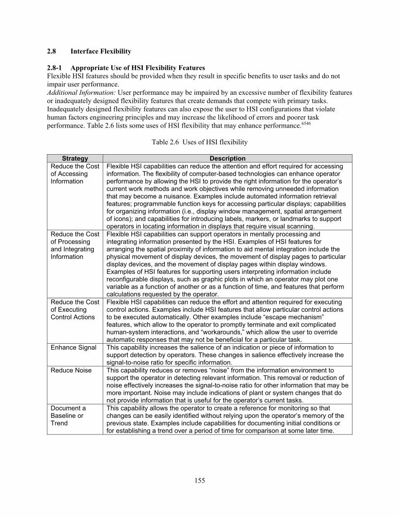
155
2.8 Interface Flexibility 2.8-1 Appropriate Use of HSI Flexibility Features Flexible HSI features should be provided when they result in specific benefits to user tasks and do not impair user performance. Additional Information: User performance may be impaired by an excessive number of flexibility features or inadequately designed flexibility features that create demands that compete with primary tasks. Inadequately designed flexibility features can also expose the user to HSI configurations that violate human factors engineering principles and may increase the likelihood of errors and poorer task performance. Table 2.6 lists some uses of HSI flexibility that may enhance performance.6546
Table 2.6 Uses of HSI flexibility
Strategy Description Reduce the Cost of Accessing Information
Flexible HSI capabilities can reduce the attention and effort required for accessing information. The flexibility of computer-based technologies can enhance operator performance by allowing the HSI to provide the right information for the operator’s current work methods and work objectives while removing unneeded information that may become a nuisance. Examples include automated information retrieval features; programmable function keys for accessing particular displays; capabilities for organizing information (i.e., display window management, spatial arrangement of icons); and capabilities for introducing labels, markers, or landmarks to support operators in locating information in displays that require visual scanning.
Reduce the Cost of Processing and Integrating Information
Flexible HSI capabilities can support operators in mentally processing and integrating information presented by the HSI. Examples of HSI features for arranging the spatial proximity of information to aid mental integration include the physical movement of display devices, the movement of display pages to particular display devices, and the movement of display pages within display windows. Examples of HSI features for supporting users interpreting information include reconfigurable displays, such as graphic plots in which an operator may plot one variable as a function of another or as a function of time, and features that perform calculations requested by the operator.
Reduce the Cost of Executing Control Actions
Flexible HSI capabilities can reduce the effort and attention required for executing control actions. Examples include HSI features that allow particular control actions to be executed automatically. Other examples include “escape mechanism” features, which allow to the operator to promptly terminate and exit complicated human-system interactions, and “workarounds,” which allow the user to override automatic responses that may not be beneficial for a particular task.
Enhance Signal This capability increases the salience of an indication or piece of information to support detection by operators. These changes in salience effectively increase the signal-to-noise ratio for specific information.
Reduce Noise This capability reduces or removes “noise” from the information environment to support the operator in detecting relevant information. This removal or reduction of noise effectively increases the signal-to-noise ratio for other information that may be more important. Noise may include indications of plant or system changes that do not provide information that is useful for the operator’s current tasks.
Document a Baseline or Trend
This capability allows the operator to create a reference for monitoring so that changes can be easily identified without relying upon the operator’s memory of the previous state. Examples include capabilities for documenting initial conditions or for establishing a trend over a period of time for comparison at some later time.
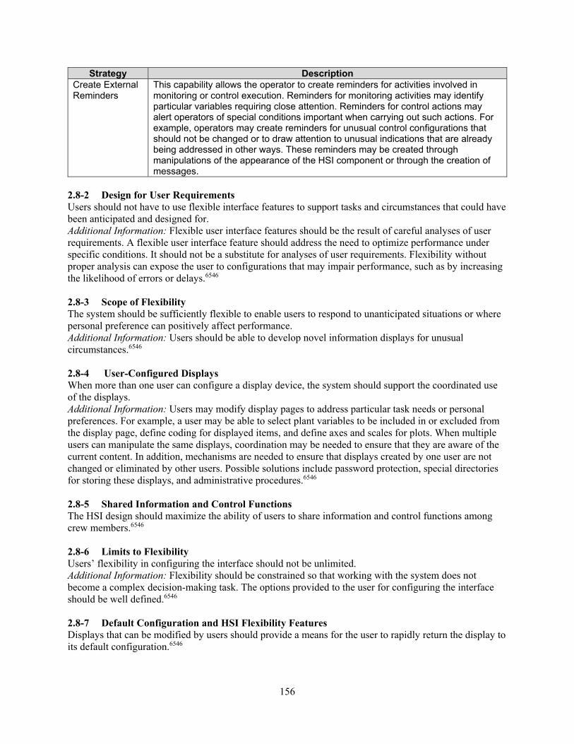
156
Strategy Description Create External Reminders
This capability allows the operator to create reminders for activities involved in monitoring or control execution. Reminders for monitoring activities may identify particular variables requiring close attention. Reminders for control actions may alert operators of special conditions important when carrying out such actions. For example, operators may create reminders for unusual control configurations that should not be changed or to draw attention to unusual indications that are already being addressed in other ways. These reminders may be created through manipulations of the appearance of the HSI component or through the creation of messages.
2.8-2 Design for User Requirements Users should not have to use flexible interface features to support tasks and circumstances that could have been anticipated and designed for. Additional Information: Flexible user interface features should be the result of careful analyses of user requirements. A flexible user interface feature should address the need to optimize performance under specific conditions. It should not be a substitute for analyses of user requirements. Flexibility without proper analysis can expose the user to configurations that may impair performance, such as by increasing the likelihood of errors or delays.6546 2.8-3 Scope of Flexibility The system should be sufficiently flexible to enable users to respond to unanticipated situations or where personal preference can positively affect performance. Additional Information: Users should be able to develop novel information displays for unusual circumstances.6546 2.8-4 User-Configured Displays When more than one user can configure a display device, the system should support the coordinated use of the displays. Additional Information: Users may modify display pages to address particular task needs or personal preferences. For example, a user may be able to select plant variables to be included in or excluded from the display page, define coding for displayed items, and define axes and scales for plots. When multiple users can manipulate the same displays, coordination may be needed to ensure that they are aware of the current content. In addition, mechanisms are needed to ensure that displays created by one user are not changed or eliminated by other users. Possible solutions include password protection, special directories for storing these displays, and administrative procedures.6546
2.8-5 Shared Information and Control Functions The HSI design should maximize the ability of users to share information and control functions among crew members.6546 2.8-6 Limits to Flexibility Users’ flexibility in configuring the interface should not be unlimited. Additional Information: Flexibility should be constrained so that working with the system does not become a complex decision-making task. The options provided to the user for configuring the interface should be well defined.6546 2.8-7 Default Configuration and HSI Flexibility Features Displays that can be modified by users should provide a means for the user to rapidly return the display to its default configuration.6546

157
2.8-8 Changes to Display Characteristics Users should not be able to change display characteristics that have been specifically designed to convey information important to their tasks. Additional Information: The HSI may allow users to change or adjust some of its characteristics, if these changes will enhance personnel performance. However, users should not be able to change display characteristics that have been specifically designed to convey important information, such as coding schemes. Examples for graphic elements include size, shape, and color codes for icons, symbols, borders, lines, and arrows. Examples for text elements include font characteristics (e.g., size, style, and color), abbreviations and acronyms for messages, and labels.6546 2.8-9 User Expertise and HSI Flexibility Features The design of flexible HSI features should provide capabilities that are consistent with the levels of expertise of the users. Additional Information: User needs are typically different for different levels of expertise. Users who have limited exposure to the advanced capabilities of computer-based HSI components may require a high degree of support for interface management actions, such as with menu-based systems and computer-based help features. Users who are highly proficient in the use of the HSI may require features that limit the number of steps required to complete an action, such as through a command-based interface rather than a menu-based interface.6546 2.9 System Security 2.9.1 User Identification 2.9.1-1 Data Protection Measures should be taken to protect data security. Additional Information: This guideline addresses the need for strategies to protect important data in a system (e.g., setpoints and control logic values, for intentional or inadvertent changes (or loss)). Since changing such information can only be properly accomplished by specific individuals who are authorized to make such changes, HSI design measures should support the prevention of modifications by unauthorized individuals. This may be accomplished in different ways (e.g., use of a password to gain access or requirement for supervisor approval (through the HSI) to enable changes, checks on input values for reasonableness, and feedback to users if an input value is predefined as unreasonable). 5908 2.9.1-2 Notification of Threats to Security Messages or signals should notify users (and system administrators) of potential threats to data security (i.e., of attempted intrusion by unauthorized users). Additional Information: For protecting data from unauthorized use, it may not be enough merely to resist intrusion. It may also be helpful if the computer can detect and report any intrusion attempts. In the face of persistent intrusion attempts, it may be desirable to institute countermeasures of some sort, such as changing user passwords or establishing other more stringent user authentication procedures.5908 2.9.1-3 Auxiliary Tests To Authenticate User Identity When system security requires more stringent user identification than password entry provides, auxiliary tests should be devised that authenticate user identity without imposing impractical demands on the user’s memory.5908 2.9.1-4 Easy Logon The logon process and procedures for user identification should be as simple as possible, consistent with protecting the system and associated data.

158
Additional Information: The logon process should provide prompts for all user entries, including passwords and whatever other data are required to confirm user identity and to authorize access to the system. Authentication of user identity is generally not enhanced by requiring a user to enter routine data such as terminal, telephone, office, or project numbers. In most organizations, those data can readily be obtained by other people. If verification of those data is needed, the user should be asked to review and confirm currently stored values in a supplementary procedure following logon.5908 2.9.1-5 Private Entry of Passwords When a user must enter a password, password entry should not be displayed. Additional Information: Covert entry of passwords will prevent casual eavesdropping by onlookers. This represents an exception to the general recommendation that all entries should be displayed. Special characters (e.g., * or #) may be displayed with each keystroke rather than the actual characters being entered. Alternatively, blanks may be displayed accompanied by an audio cue (e.g., a click or beep) for keystroke feedback.5908 2.9.1-6 User Choice of Passwords When passwords are required, users should be allowed to choose their own passwords and to change their passwords as needed. Additional Information: Where data protection is critical, user-selected passwords should be tested against a list of common passwords (for example, “me,” car types, names spelled backwards (“nhoj”), or birth dates). A password chosen by a user will generally be easier for that individual to remember. Security is enhanced if users are readily able to change their passwords (e.g., a user may suspect that a password has been disclosed, and thus may wish to change it).5908 2.9.1-7 Limiting Unsuccessful Logon Attempts A maximum limit on the number and rate of unsuccessful logon attempts should be imposed. Additional Information: These limits should provide a margin for user error while protecting the system from persistent attempts at illegitimate access. A record of continuing failure by any particular user to complete successful logon procedures, including password entry and other tests of claimed user identity, may indicate persistent intrusion attempts or lack of fitness for duty. Thus, repeated logon failures might be grounds for denying access to that user. Access might be denied temporarily for some computer-imposed time interval, or indefinitely, pending review by a system administrator. Legitimate users will sometimes have difficulty completing a successful logon, perhaps due to inattention, or a faulty terminal, or faulty communications. The system should tolerate occasional logon failures of that kind, with the user simply invited to try again.5908 2.9.1-8 Continuous Recognition of User Identity Once a user’s identity has been authenticated, any authorized data access or change privileges for that user should continue throughout a work session. Additional Information: An identified user who is required to take separate actions to authenticate data handling transactions, such as accessing particularly sensitive files or issuing particular commands, may degrade the efficiency of system operations. Where continuous verification of user identity seems required for data protection, some automatic means of identification might be employed for that purpose.5908 2.9.1-9 Single Authorization for Data Entry or Change User authorization should be established at initial logon.5908
159
2.9.1-10 Logging On When users must log on to a system, logon should be a separate procedure that is completed before a user may select any operational options.5908 2.9.1-11 Logon Frame The logon frame should appear as soon as possible on the display with no additional user involvement.5908 2.9.1-12 Logon Delays Logon delays should be accompanied by an advisory message to tell the user its current status and when the system will become available.5908 2.9.1-13 Immediate Start of Productive Work After completing the logon process, the user should be able to start productive work immediately.5908 2.9.1-14 Logging Off If there are pending actions and the user requests a logoff, the system should inform the user that these actions will be lost and allow the user to cancel either the pending actions or the logoff.5908 2.9.1-15 Saving Open Files in Automatic Logoff Where possible, in the event of automatic logoff, open files should be saved to some defined file name. Additional Information: For example, link User’s Name + Date.5908 2.9.1-16 Automatic Logoff Interactive timesharing systems should allow some specified time between keyboard actions before automatic logoff unless the user asks for a longer period.5908 2.9.1-17 Audible Signal for Automatic Logoff An audible signal should be presented at specified intervals before automatic logoff.5908 2.9.2 Information Access 2.9.2-1 Encryption When sensitive data may be exposed to unauthorized access, a capability for encrypting those data should be provided. Additional Information: Since potential exposure may be assumed during any external data transmission, encryption should be imposed routinely by the computer. Users should not be relied upon to request encryption. For protection of data within a shared system, a user might choose to encrypt private files to prevent their reading by other people. In such a case, the user must specify a private encryption “key,” which will then serve as the basis for automatic encryption by the computer.5908 2.9.2-2 Ensuring Reversible Encryption Encrypted data should be protected from any change that might prevent successful reversal of their encryption.5908 2.9.2-3 Displayed Security Classification When displayed data are classified for security purposes, each display should include a prominent indication of security classification. Additional Information: Where a display includes partitioned “windows” of data from different sources, it may be necessary to label security classification separately for each window. Under those conditions, some form of auxiliary coding (e.g., color coding) might help users distinguish a window that contains data at a high security level. This practice will serve to remind users of the need to protect classified data,

160
both in access to the display itself and in any further dissemination of displayed data.5908 2.9.2-4 Display Suppression for Security When confidential information is displayed at a workstation that might be viewed by casual onlookers, the user should be provided with some rapid means of temporarily suppressing a current display, if its privacy is threatened, and then resuming work later. Additional Information: A suppressed display should not be entirely blank but should contain an appropriate message indicating its current status (e.g., "Display is temporarily suppressed; enter password to resume work.” Such a capability is sometimes called a “security pause.” For quick display suppression, a function key might be provided. To retrieve a suppressed display and resume work, a user might be required to make a code entry such as a password, in the interests of data protection.5908 2.9.2-5 Protecting Printed Data As required for security, procedures to control access to printed data should be established, rather than simply prohibiting the printing of sensitive data. Additional Information: User requirements for printed data are often unpredictable, and printing restrictions may handicap task performance. Rather than restrict printing, establish appropriate procedures for restricting further distribution of data printouts.5908 2.9.2-6 Protecting Display Formats Display formatting features, such as field labels and delimiters, should be protected from accidental change by users. Additional Information: In many data entry tasks, users will be allowed to change data fields but should be prevented from making any structural changes to the display. In applications where a user may have to create or modify display formats, special control actions should be provided for that purpose.5908 2.9.2-7 Protecting Displayed Data When protection of displayed data is essential, computer control over the display should be maintained. Additional Information: It is not enough simply to instruct users not to make changes in displayed data. Users may attempt unwanted changes by mistake, or for curiosity, or perhaps even to subvert the system.5908 2.9.2-8 Indicating “Read-Only” Displays When users are not authorized to change displayed data, the display should indicate “read-only” status. Additional Information: In applications where the use of read-only displays is common, some simple cue in the display header may suffice to indicate that status. In applications where users can usually make additions and corrections to displayed data, any exception to that practice may confuse a user and so should be noted more prominently on the display.5908 2.9.2-9 Automatic Records of Data Access When records of data access are necessary, the records should be maintained automatically. Additional Information: Transaction records and logs should be stamped with user identifiers, time, and date. Provisions should be made to control requests for records and logs of data transactions with classified material. Users should be informed concerning the nature and purpose of automated recording of individual actions. Even cooperative, well-intentioned users can forget to keep manual logs of data access and will resent the time and effort required to keep such logs. Subversive users, of course, cannot be expected to provide accurate records.5908

161
3 ANALOG DISPLAY AND CONTROL DEVICES
Analog Controls and Display Devices Characterization Most nuclear power plants, even newer designs, have analog control and display devices. Operators in older plants primary rely on these devices to monitor and control the plant. These are physical devices, such as push buttons and meters, that are not viewed through a computer device (although some computer display designs contain mimics of analog devices). This section contains review guidance for such devices. The guidance is organized into two subsections: “Analog Control Devices” and “Analog Display Devices.” The paragraphs below describe each of these subsections. Analog Control Devices Analog controls are devices for providing control input. Each control typically has a single dedicated location in a control panel. Analog controls usually have either discrete settings or a continuous range for adjustment. Those with discrete settings typically have one of two types of operation—momentary and latching. Momentary control returns to its original setting when released. A latching control stays in position until operated again. The review guidance includes general control considerations as well as several different types of controls. General Control Guidelines There are general considerations for the review of any controls. They are divided into two subsections. The first addresses design principles, such as control stability, location, feedback, and accidental actuation prevention. The second subsection addresses the coding of controls. Section 3.1.1 provides review guidelines for general control considerations. Pushbutton Controls These are buttons that generate a signal when they are pressed with the finger or hand. Their shape (e.g., round or square), size, and texture may vary. Legend pushbuttons are illuminated by internal lamps; their faces may contain alphanumeric text. Section 3.1.2 provides review guidelines for pushbutton controls. Slide Switches These controls are operated by sliding a knob linearly in the horizontal or vertical direction. Section 3.1.3 provides review guidelines for slide switches. Toggle Switches These are stemmed switches that the user can move to discrete settings. Section 3.1.4 provides review guidelines for toggle switches. Rocker Switches These switches have nearly flat faces and can be moved by the user to discrete settings. Section 3.1.5 provides review guidelines for rocker switches.

162
Rotary Controls These controls are operated with a rotary motion. They include J-handle controls, key-operated controls, continuous adjustment controls, thumbwheels, and rotary selector controls. Section 3.1.6 provides review guidelines for rotary controls. Manual Valves These are the controls for operating manual valves. Section 3.1.7 provides review guidelines for manual valves. Analog Display Devices Display devices are used to present information to personnel. The review guidance includes several different types of displays, including meters, light indicators, and numeric readouts. Meters A meter is an indicator that typically features a numeric scale and a needle. Two types of meters are fixed scale (i.e., the needle moves across the scale) and moving scale (i.e., the scale moves behind the needle). Section 3.2.1 presents review guidelines. Light Indicators These are display devices containing lamps that indicate status or states through the presence or absence of illumination. For example, an illuminated light indicator may be used to show that a breaker is closed. Section 3.2.2 presents review guidelines. Numeric Readouts A numeric readout is a display device that presents data as a string of numerals (digits). Section 3.2.3 presents review guidelines. Valve Position Indication A numeric readout valve position indication is a display device that presents information about the position of a manual valve. Section 3.2.4 presents review guidelines. A comprehensive review of analog display and control devices should include how they are affected by degraded human-system interface (HSI) and instrumentation and control conditions. Degraded conditions can have significant impacts on proper HSI functioning. Section 14 provides guidance for reviewing these degraded HSI and instrumentation and control conditions. Bibliography Source Code Documents 0700 U.S. Nuclear Regulatory Commission (1981). Guidelines for Control Room Design Reviews
(NUREG-0700, Rev. 0). Washington, DC: U.S. Nuclear Regulatory Commission. 1472F U.S. Department of Defense (2000). Human Engineering Design Criteria for Military Systems,

163
Equipment and Facilities (MIL-STD 1472F). Washington, DC: U.S. Department of Defense. 3659 Kinkade, R.G., and Anderson, J. (1984). Human Factors Guide for Nuclear Power Plant Control
Room Development (EPRI NP-3659). Electric Power Research Institute, Palo Alto, CA. 5908 O’Hara, J., Brown, W., Baker, C., Welch, D., Granda, T., and Vingelis, P. (1994). Advanced
Human-System Interface Design Review Guideline (NUREG/CR-5908, Vol. 2). Washington, DC: U.S. Nuclear Regulatory Commission.
6146 Brown, W., Higgins, J., and O’Hara, J. (1994). Local Control Stations: Human Engineering
Issues and Insights (NUREG/CR-6146). Washington, DC: U.S. Nuclear Regulatory Commission. 3.1 Analog Controls 3.1.1 General Control Guidelines 3.1.1.1 Design Principles 3.1.1.1-1 Input Device Stability Control devices should be stable during normal usage (i.e., they should not slip or rock, unless such actions are part of the controller operation).5908 3.1.1.1-2 Feedback Visual or auditory feedback should be provided to indicate that the system has received a control input. Additional Information: This is especially important when the control surface does not depress or move (such as with a force joystick or touchscreen), thereby providing little tactile feedback to the user.5908 3.1.1.1-3 Accidental Input or Actuation Prevention The system should be located and designed to prevent the accidental manipulation of control and input devices that could result in changes to the status of the system functions, components, or data. Additional Information: Controls may be recessed, shielded, or otherwise surrounded by physical barriers. The control should be entirely contained within the envelope described by the recess or barrier. Controls may be covered or guarded with movable (e.g., hinged) barriers. Safety or lock wires should not be used. When a movable control guard is in the open position, it should not interfere with the operation of the guarded control or other adjacent controls. Controls may have interlocks. The interlocking controls may require: (1) extra movement (e.g., a side movement out of a detent position or a pull-to-engage clutch), or (2) prior operation of a related or locking control.5908, 0700 3.1.1.1-4 Location Controls should be operable from the location where the user is most likely to need to interact with the system.0700 3.1.1.1-5 Speed Controls should provide a rapid selection of choices.0700 3.1.1.1-6 Accuracy The accuracy of the control device or method should be commensurate with the functions to be served.0700 3.1.1.1-7 Displacement Control design should allow the user freedom of movement to perform other duties.0700
164
3.1.1.1-8 Range and Precision Control should provide the sufficient range and precision required by the task.0700 3.1.1.1-9 Economy Each control or input device should be necessary, use minimal space, and be the simplest effective control for the task concerned. Additional Information: There should be a good reason to require a control for the function concerned. Duplication of controls should not occur, except for a specific reason. The precision and range of a control should not greatly exceed the need.0700 3.1.1.1-10 Suitability for Control Room Environment Controls and input devices should be suitable for use in a control room environment. Additional Information: Controls and input devices should be suited to the anthropometric and ergonometric characteristics of the expected user population. Each should be recognizable in terms of its function and should be of the type normally anticipated for the operation concerned. This means conforming to user expectations, matching to other devices having similar functions, and generally conforming to conventional practice.0700 3.1.1.1-11 Compatibility with Emergency Gear If used while wearing protective equipment (e.g., oxygen masks and protective gloves), controls and input devices should be easy to identify and activate, or use.0700 3.1.1.1-12 Durability Controls and input devices should be sufficiently rugged to withstand normal and emergency use. Additional Information: Each device should retain its appearance, “feel,” and functional characteristics during its service life. Broken, chipped, or crumbled control surfaces should not ordinarily occur. Control knobs or handles should not rotate, slip, or move loosely on their shafts. No internal wear or breakage should occur which alters the “feel” or other sensory feedback of a control. Controls should not develop internal looseness, binding, or backlash.0700 3.1.1.1-13 Control Activation Controls and input devices should require distinct or sustained effort for activation. Additional Information: Conventional controls should be provided with resistance (e.g., friction or spring-loading). Activation of computer-displayed controls should require a separate action, distinct from pointing.0700 3.1.1.1-14 Sequential Activation When a strict sequential activation is necessary, controls should have locks to prevent the controls from passing through a position. Additional Information: Movement to the next position should require a new control action.0700 3.1.1.1-15 Population Stereotypes Control movements should conform to population stereotypes (see Figure 3.1). Additional Information: The following are control movement stereotypes for the U.S. population: (1) on, start, run, open; up, right, forward, clockwise, pull, (2) off, stop, close; down, left, backward, counterclockwise, push, (3) right; clockwise, right, (4) left; counterclockwise, left, (5) raise; up, (6) lower; down, (7) increase; forward, up, right, clockwise, (8) decrease; backward, down, left, counterclockwise.0700
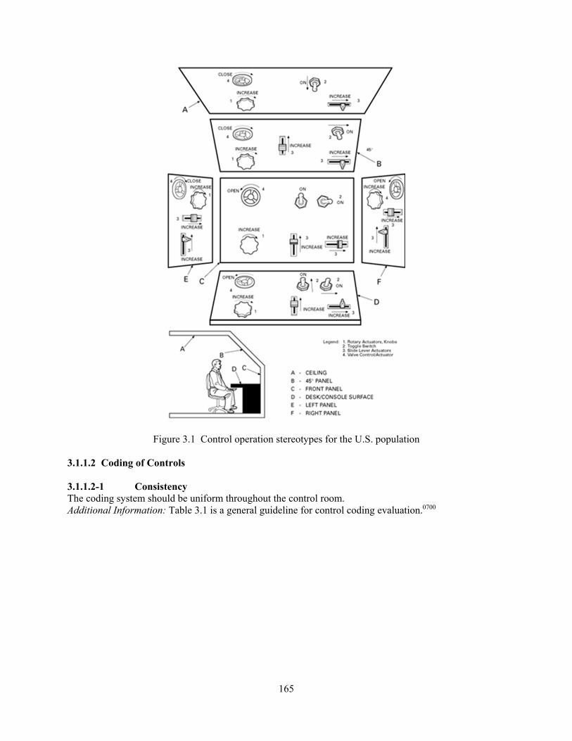
165
Figure 3.1 Control operation stereotypes for the U.S. population 3.1.1.2 Coding of Controls 3.1.1.2-1 Consistency The coding system should be uniform throughout the control room. Additional Information: Table 3.1 is a general guideline for control coding evaluation.0700

166
Table 3.1 Advantages and disadvantages of various types of coding
Advantages
Type of Coding Location Shape Size Mode of
Operation Labeling Color
Improves visual identification X X X X X Improves nonvisual identification (tactual and kinesthetic) X X X X
Helps standardization X X X X X X Aids identification under low levels of illumination and colored lighting X X X X
(when trans-
illumin- ated)
(when trans-illuminated)
May aid in identifying control position (settings) X X X
Requires little (if any) training; is not subject to forgetting X
Disadvantages May require extra space X X X X X Affects manipulation of the use of the control (ease of use) X X X X
Limited in number of available coding categories X X X X X
May be less effective if operator wears gloves X X X
Controls must be viewed (i.e., must be within visual areas and with adequate illumination present)
X X
3.1.1.2-2 Size Coding Levels No more than three different sizes of controls should be used for discrimination by absolute size. Additional Information: When knob diameter is used as a coding parameter, differences between diameters should be at least 12.7 millimeters (mm) (0.5 inch). (When knob thickness is a coding parameter, differences between thicknesses should be at least 10.2 mm (0.4 inch).0700 3.1.1.2-3 Size Coding Uniformity Controls used for performing the same function on different equipment should be the same size.0700 3.1.1.2-4 Shape Coding When possible, controls should be differentiated by shape. Additional Information: The shapes of conventional controls should be identifiable both visually and tactually to facilitate “blind” manipulation. Shape coding is used as following: (1) The coded feature should not interfere with ease of control manipulation. (2) Shapes should be identifiable by the hand regardless of the position and orientation of the control
knob or handle. (3) Shapes should be tactually identifiable when gloves are worn. (4) A sufficient number of identifiable shapes should be provided to cover the expected number of
controls that require tactual identification.
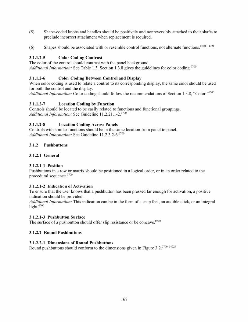
167
(5) Shape-coded knobs and handles should be positively and nonreversibly attached to their shafts to preclude incorrect attachment when replacement is required.
(6) Shapes should be associated with or resemble control functions, not alternate functions.0700, 1472F 3.1.1.2-5 Color Coding Contrast The color of the control should contrast with the panel background. Additional Information: See Table 1.3. Section 1.3.8 gives the guidelines for color coding.0700 3.1.1.2-6 Color Coding Between Control and Display When color coding is used to relate a control to its corresponding display, the same color should be used for both the control and the display. Additional Information: Color coding should follow the recommendations of Section 1.3.8, “Color.”0700 3.1.1.2-7 Location Coding by Function Controls should be located to be easily related to functions and functional groupings. Additional Information: See Guideline 11.2.21.1-2.0700 3.1.1.2-8 Location Coding Across Panels Controls with similar functions should be in the same location from panel to panel. Additional Information: See Guideline 11.2.3.2-6.0700 3.1.2 Pushbuttons 3.1.2.1 General 3.1.2.1-1 Position Pushbuttons in a row or matrix should be positioned in a logical order, or in an order related to the procedural sequence.0700 3.1.2.1-2 Indication of Activation To ensure that the user knows that a pushbutton has been pressed far enough for activation, a positive indication should be provided. Additional Information: This indication can be in the form of a snap feel, an audible click, or an integral light.0700 3.1.2.1-3 Pushbutton Surface The surface of a pushbutton should offer slip resistance or be concave.0700 3.1.2.2 Round Pushbuttons 3.1.2.2-1 Dimensions of Round Pushbuttons Round pushbuttons should conform to the dimensions given in Figure 3.2.0700, 1472F

168
Figure 3.2 Recommended dimensions for unguarded and nonrecessed pushbuttons
3.1.2.2-2 Resistance of Round Pushbuttons Resistance should be 2.8 to 11.1 N [a unit of force] (10 to 40 ounces) for fingertip operation and 2.8 to 22.2 N (10 to 80 ounces) for thumb or palm operation.0700, 1472F 3.1.2.3 Legend Pushbuttons 3.1.2.3-1 Discriminability Legend pushbuttons should be readily distinguishable from legend lights. Additional Information: This may be achieved by distinctive shape, labeling, location, or other techniques.0700 3.1.2.3-2 Legend The legend should be readable under all environmental conditions. Additional Information: The legend should be readable under ambient light conditions, with or without internal illumination. The illuminated condition should be clearly recognizable under the highest predicted ambient light condition and should be at least 10 percent brighter than the surrounding panel. Legend lettering and contrast should conform to recommendations for legend lights. The legend message should be specific, unambiguous, and concise. The legend message should contain no more than three lines of lettering.0700 3.1.2.3-3 Lamp Reliability A lamp test or dual lamp/dual filament capability should be provided if the mean time between failure is less than 100,000 hours.0700, 1472F 3.1.2.3-4 Easy Replacement of Covers Lamps within the pushbutton should be replaceable from the front of the panel.0700 3.1.2.3-5 Safe Replacement of Lamps Legend pushbuttons should not short out during lamp replacement or be susceptible to inadvertent activation during the process of lamp removal or replacement.0700 3.1.2.3-6 Correct Replacement of Covers Legend covers should be keyed to prevent the possibility of interchanging the covers.0700

169
3.1.2.3-7 Barriers Barriers should be used when legend pushbuttons are contiguous. Additional Information: Barriers should have rounded edges.0700 3.1.2.3-8 Dimensions of Legend Pushbuttons Legend pushbuttons should conform to the dimensions shown in Figure 3.3.0700, 1472F
Figure 3.3 Recommended dimensions for legend pushbuttons
3.1.2.3-9 Resistance of Legend Pushbuttons Resistance should be 2.8 to 16.7 N (10 to 60 ounces).0700, 1472F 3.1.3 Slide Switches 3.1.3-1 Surface The surface of slide switches should be serrated or knurled.0700 3.1.3-2 Detents Detents should be provided for each slide switch setting. Additional Information: Resistance should gradually increase, then drop when the switch snaps into

170
position. The switch should not be capable of stopping between positions.1472F 3.1.3-3 Accidental Actuation Channel guards or other preventive features should be provided when accidental actuation would have undesirable consequences.1472F 3.1.3-4 Orientation Slide switches should be vertically oriented. Additional Information: Horizontal orientation or activation slide switches should be used only for compatibility with the controlled function or equipment location.1472F 3.1.3-5 Positive Indication Slide switches involving more than two positions should be designed to provide positive indication of the control setting, preferably a pointer located on the left side of the slide handle.1472F 3.1.3-6 Dimensions of Slide Switches Slide switches should conform to the dimensions shown in Figure 3.4.0700
Figure 3.4 Recommended dimensions for slide switches
3.1.4 Toggle Switches 3.1.4-1 Positioning To minimize the possibility of inadvertent activation or setting between control positions, toggle switches should have an elastic resistance that increases as the control is moved and drops as the switch snaps into position.0700 3.1.4-2 Feedback Toggle switches should emit an audible click or provide some other source of feedback on activation.0700 3.1.4-3 Dimensions of Toggle Switches Toggle switches should conform to the dimensions shown in Figure 3.5.0700, 1472F

171
Figure 3.5 Recommended dimensions for toggle switches
3.1.4-4 Resistance of Toggle Switches Resistance should be 2.8 to 4.4 N (10 to 16 ounces) for small switches and 2.8 to 11.1 N (10 to 40 ounces) for large switches.0700, 1472F 3.1.5 Rocker Switches 3.1.5-1 Orientation Rocker switches should ordinarily be oriented vertically. Additional Information: Activation of the upper part should control the ON or INCREASE function. Horizontal orientation should be used only when required by the location of the controlled function or equipment.0700 3.1.5-2 Indication of Activation Activation should be indicated by a snap feel, an audible click, or an integral light. Additional Information: In the ON position, the top of the switch should be flush with the panel surface.0700 3.1.5-3 Resistance Control resistance should gradually increase, then drop to zero when the control snaps into position. Additional Information: This resistance should keep the switch from being placed between positions.0700 3.1.5-4 Inadvertent Activation If it controls a critical function, the switch should be protected by channel guards or other means to prevent inadvertent activation.0700

172
3.1.5-5 Dimensions of Rocker Switches Rocker switches should conform to the dimensions shown in Figure 3.6.0700, 3659, 1472F
Figure 3.6 Recommended dimensions for rocker switches 3.3.5-6 Resistance of Rocker Switches Resistance should be 2.8 to 11.1 N (10 to 40 ounces).0700, 3659, 1472F 3.1.6 Rotary Controls 3.1.6.1 General 3.1.6.1-1 Direction of Activation Rotary control settings should increase in value with a clockwise rotation.0700 3.1.6.1-2 Rotary Control Shape Coding Shape coding should be employed if rotary controls used for widely different functions are placed on the same panel.0700 3.1.6.1-3 Coding Specifications Shape-coded rotary controls should be visually and tactually identifiable.0700 3.1.6.1-4 Rotating Knob Shape Options Rotating knob controls for different types of control actions should be distinguishable by sight and touch

173
and not easily confused with each other. Additional Information: Figure 3.7 gives examples of suitable knob designs developed for three major classes of knobs, each class intended for a different purpose: multiple rotation, fractional rotation, and detent positioning.0700
Figure 3.7 Shape-coded rotary controls
3.1.6.1-5 Rotary Action Control Applications Rotary action controls should be used in situations where linear or pushbutton controls would be subject to inadvertent activation and fixed protective structures are impractical or inappropriate.0700
3.1.6.2 J-Handles 3.1.6.2-1 Dimensions of J-Handles High torque J-handles should conform to the dimensions shown in Figure 3.8.0700, 3659
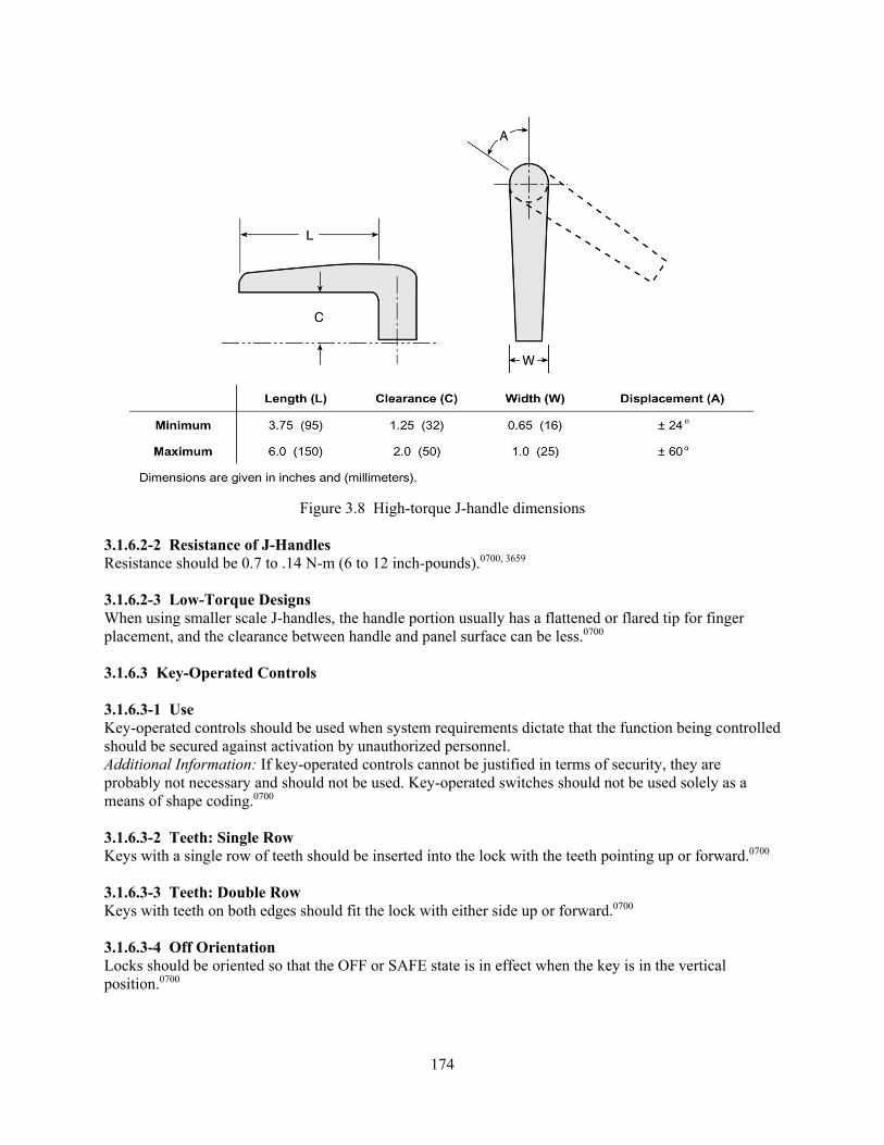
174
Figure 3.8 High-torque J-handle dimensions
3.1.6.2-2 Resistance of J-Handles Resistance should be 0.7 to .14 N-m (6 to 12 inch-pounds).0700, 3659 3.1.6.2-3 Low-Torque Designs When using smaller scale J-handles, the handle portion usually has a flattened or flared tip for finger placement, and the clearance between handle and panel surface can be less.0700 3.1.6.3 Key-Operated Controls 3.1.6.3-1 Use Key-operated controls should be used when system requirements dictate that the function being controlled should be secured against activation by unauthorized personnel. Additional Information: If key-operated controls cannot be justified in terms of security, they are probably not necessary and should not be used. Key-operated switches should not be used solely as a means of shape coding.0700 3.1.6.3-2 Teeth: Single Row Keys with a single row of teeth should be inserted into the lock with the teeth pointing up or forward.0700 3.1.6.3-3 Teeth: Double Row Keys with teeth on both edges should fit the lock with either side up or forward.0700 3.1.6.3-4 Off Orientation Locks should be oriented so that the OFF or SAFE state is in effect when the key is in the vertical position.0700

175
3.1.6.3-5 Key Removal Users should not normally be able to remove the key from the lock unless the switch is turned to the OFF or SAFE position.0700 3.1.6.3-6 Labeling Control positions should be labeled.0700 3.1.6.3-7 Actuation of Key Switch Actuation of an item by a key-operated switch should be accomplished by turning the key clockwise from the vertical OFF (i.e., upright) position.1472F 3.1.6.3-8 Dimensions of Key-Operated Controls Key-operated control dimensions should conform to the dimensions shown in Figure 3.9.0700, 1472F
Figure 3.9 Key-operated control dimensions
3.1.6.3-9 Resistance of Key-Operated Controls The resistance of key-operated controls should be 0.11 to 0.68 N-m (1 to 6 inch-pounds).0700, 1472F 3.1.6.4 Continuous Adjustment Controls 3.1.6.4-1 Knobs Knobs for continuous adjustment controls should be round in shape, with knurled or serrated edges.0700 3.1.6.4-2 Position Indication When an indication of position is desirable, it should allow the user to easily recognize the position. Additional Information: The pointer configurations shown at the bottom of Figure 3.4 may be used. Where more accuracy is required, a line should be engraved (and filled with contrasting pigment) both on top and down the side of the pointer, as shown on the knob at the bottom of the figure.0700

176
3.1.6.4-3 Knob Dimensions Fingertip grasp knobs should be between 13 and 25 mm (0.5 and 1 inch) in height and between 10 and 100 mm (0.375 and 4 inches) in diameter. Thumb and forefinger encircled knobs should be between 25 and 75 mm (1 and 3 inches) in diameter.0700 3.1.6.4-4 Knob Torque Knob torque should be within the range of 32 to 42 mN-m (4.5 to 6.0 inch-ounces).0700 3.1.6.4-5 Dimensions of Knobs with Skirts Knobs with skirts should conform to the dimensions shown in Figure 3.10.0700
Figure 3.10 Recommended dimensions for rotary controls with finger stops and skirts
3.1.6.5 Thumbwheels 3.1.6.5-1 Visibility To minimize error, thumbwheel readouts should be visible from the thumbwheel operating position.0700 3.1.6.5-2 Coding If the thumbwheel is used as an input device, the off, zero, or normal position should be coded to facilitate visual recognition of status.0700 3.1.6.5-3 Dimensions of Continuous Adjustment Thumbwheels At least 25.4 mm (1 inch) of circumference of a continuous adjustment thumbwheel should be exposed to permit easy manipulation. Additional Information: A continuous adjustment thumbwheel control moves smoothly (i.e., its motion is not “stepped” like that of a discrete thumbwheel control).0700 3.1.6.5-4 Resistance of Continuous Adjustment Thumbwheels The resistance of a continuous adjustment thumbwheel should be between 0.8 to 1.7 N (3 and 6 ounces).

177
Additional Information: A continuous adjustment thumbwheel control moves smoothly (i.e., its motion is not “stepped like that of a discrete thumbwheel control.0700 3.1.6.5-5 Dimensions of Discrete Thumbwheel Controls Discrete thumbwheel controls should conform to the dimensions shown in Figure 3.11.0700, 1472F
Figure 3.11 Recommended dimensions for discrete thumbwheel controls
3.1.6.5-6 Resistance of Discrete Thumbwheel Controls The resistance of discrete thumbwheel controls should be 1.7 to 5.6 N (6 to 20 ounces).0700, 1472F
3.1.6.6 Rotary Selector Controls 3.1.6.6-1 Selection Rotary selector controls should be used when three or more detented positions are required and may also be used for two-detented position operation.0700
3.1.6.6-2 Positioning Detents should be provided at each control position to ensure proper positioning of a discrete rotary control. Additional Information: It should not be possible to position a control between detented positions. To minimize the possibility of placing a rotary selector in an unused position, stops should be provided at the limits of the control range. A maximum of 24 positions should be used on a rotary selector control.0700 3.1.6.6-3 Readability Rotary controls should have a moving pointer and fixed position settings to maximize readability.0700 3.1.6.6-4 Position Indication Position indication should be provided. Additional Information: Desirable alternatives are: (1) illuminated indicator lights, (2) a line engraved both on the top of the knob and down the side, or (3) a pointer shape. It should not be possible to confuse the position of the knob in reference to position markers on the panel. To minimize the problem of parallax, pointers on knobs should be mounted close to the settings to which they point.0700
178
3.1.6.6-5 Dimensions of Rotary Selector Controls Rotary selector controls should conform to the dimensions shown in Figure 3.12. 0700, 1472F
Figure 3.12 Recommended dimensions for rotary selector switches
3.1.6.6-6 Resistance of Rotary Selector Controls Resistance should be 0.11 to 0.68 N-m (1 to 6 inch-pounds).0700, 1472F 3.1.6.6-7 Momentary Contact Rotary Selector Controls Knobs for spring-loaded momentary contact rotary selector controls should be large enough to be easily held against the spring torque, without fatigue, for as long as necessary to accomplish the control action.0700 3.1.7 Manual Valves 3.1.7-1 Operating Labels Handwheels should be provided with double-ended arrows showing the direction of operations and labeled at each end to indicate the functional result (i.e., open and close).6146 3.1.7-2 Turning Aids Knurling, indentation, high-friction covering, or a combination of these should be built into the handwheel to allow the application of the required torque.6146 3.2 Analog Display Devices 3.2.1 Meters 3.2.1-1 Circular Scales Scale values should increase with the clockwise movement of the pointer.0700
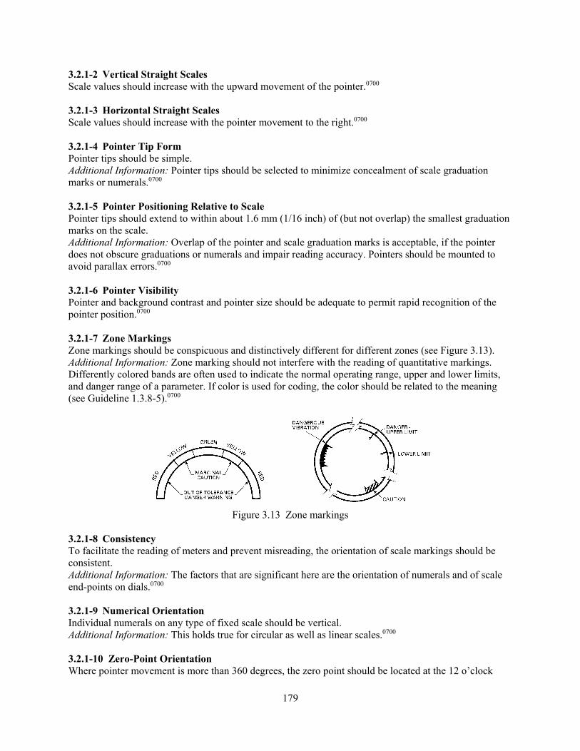
179
3.2.1-2 Vertical Straight Scales Scale values should increase with the upward movement of the pointer.0700 3.2.1-3 Horizontal Straight Scales Scale values should increase with the pointer movement to the right.0700 3.2.1-4 Pointer Tip Form Pointer tips should be simple. Additional Information: Pointer tips should be selected to minimize concealment of scale graduation marks or numerals.0700 3.2.1-5 Pointer Positioning Relative to Scale Pointer tips should extend to within about 1.6 mm (1/16 inch) of (but not overlap) the smallest graduation marks on the scale. Additional Information: Overlap of the pointer and scale graduation marks is acceptable, if the pointer does not obscure graduations or numerals and impair reading accuracy. Pointers should be mounted to avoid parallax errors.0700 3.2.1-6 Pointer Visibility Pointer and background contrast and pointer size should be adequate to permit rapid recognition of the pointer position.0700 3.2.1-7 Zone Markings Zone markings should be conspicuous and distinctively different for different zones (see Figure 3.13). Additional Information: Zone marking should not interfere with the reading of quantitative markings. Differently colored bands are often used to indicate the normal operating range, upper and lower limits, and danger range of a parameter. If color is used for coding, the color should be related to the meaning (see Guideline 1.3.8-5).0700
Figure 3.13 Zone markings
3.2.1-8 Consistency To facilitate the reading of meters and prevent misreading, the orientation of scale markings should be consistent. Additional Information: The factors that are significant here are the orientation of numerals and of scale end-points on dials.0700 3.2.1-9 Numerical Orientation Individual numerals on any type of fixed scale should be vertical. Additional Information: This holds true for circular as well as linear scales.0700 3.2.1-10 Zero-Point Orientation Where pointer movement is more than 360 degrees, the zero point should be located at the 12 o’clock
180
position. Additional Information: Where positive and negative values are displayed around a zero or null position, the zero or null point should be located at the 12 o’clock position.0700 3.2.1-11 End-Point Indication on Partial-Revolution Scales Where the scale covers less than a full rotation of the pointer, scale end-points should be indicated by a break in scale. Additional Information: The break should be at least one numbered interval in length. The break should be oriented at the 6 o’clock position.0700 3.2.1-12 Moving-Scale Meters Versus Fixed-Scale Moving-Pointer Types Moving-scale, fixed-pointer meters should be avoided in favor of the more effective fixed-scale, moving-pointer types. Additional Information: Moving-scale, fixed-pointer meters are infrequently seen in nuclear power plant control rooms.0700 3.2.2 Light Indicators 3.2.2-1 Precautions To Ensure Availability Dual-bulb or dual-filament light assemblies should be used. Additional Information: Bulb-test capability should be provided. The design should encourage immediate replacement of burned-out bulbs by providing for rapid and convenient bulb replacement with power on and without hazard to personnel or equipment.0700 3.2.2-2 Unambiguous Light Status Lights should not appear to be energized when they are off, or vice versa. Additional Information: Ambient light sources should be selected, located, or controlled to avoid reflections or refractions.0700 3.2.2-3 Positive Status Indication System and equipment status should be conveyed by illuminated indicators, never by the absence of illumination.0700 3.2.2-4 Use as Alerting Indicators Alerting the users to unfavorable status should be a function of the alarm system and not assigned to light indicators.0700 3.2.2-5 Identification of Meaning Where the meaning of a light indicator is not apparent, labeling should be provided close to the indicator showing the condition that the light represents.0700 3.2.2-6 Light Intensity The illuminated indicator should be at least 10 percent greater in light intensity than the surrounding panel as measured by a spot photometer.0700 3.2.2-7 Visibility of Light Indicators When using legend light indicators, make sure contrast and ambient and transilluminated conditions are considered. Additional Information: Light intensity of the illuminated indicators should be at least 10 percent greater than the surrounding panel as measured by a spot photometer. Legends should be legible under ambient illumination with indicator lights off. Legend lettering should contrast well with background under both
181
ambient and transilluminated lighting.0700 3.2.2-8 Legend Design General legend design should be consistent throughout the control room. Additional Information: Lettering should be simple and should follow Guidelines 1.3.1-2 and 1.3.1-4 for style and size. Symbolic legends should be clear and unambiguous as to their meaning. Text should be short, concise, and unambiguous. Legend messages should contain no more than three lines of text. Nomenclature and abbreviations should be standard and consistent with usage throughout the control room and in the procedures. Legends should be worded to tell the status indicated by the glowing light.0700 3.2.2-9 Distinguishability from Legend Pushbuttons Illuminated legend indicators should be readily distinguishable from legend pushbuttons by form, size, or other factors. Additional Information: Section 3.3.1.3, “Legend Pushbuttons” gives guidelines for legend pushbuttons.0700 3.2.2-10 Color Coding The color of the legend background under transillumination should be clearly identifiable and should conform to the general color code established for the control room. Additional Information: See Section 1.3.8, “Color.”0700 3.2.2-11 Replacing Indicator Lenses Provisions should be made to prevent interchanging indicator lenses. Additional Information: The means for preventing lenses from being interchanged can be mechanical or procedural.0700 3.2.3 Numeric Readouts 3.2.3-1 Orientation Multidigit numbers formed by several elements (e.g., drums and light-emitting diode arrays) should be read horizontally from left to right. Additional Information: Numbers should not be oriented vertically (i.e., read top to bottom).0700 3.2.3-2 Width-to-Height Ratio in Drum Displays To compensate for the distortion imposed by the curved surface of the drum, counter numerals should reflect a width-height ratio of 1:1. Additional Information: Do not use a 3:5 ratio, as recommended for numerals of other displays.0700, 5908 3.2.3-3 Grouping of Numerals If more than four digits are required, they should be grouped and the groupings separated, as appropriate, by commas, by a decimal point, or by additional space.0700 3.2.3-4 Display of Changing Values Numerals should not follow each other faster than one per second when the user is expected to read the numerals consecutively. Additional Information: Drum displays should change by snap action rather than through continuous movement and should move upward with increasing values. The window through which numerals appear should be sized to allow no more than one digit per drum to appear in the window at any one time.0700, 3659

182
3.2.4 Valve Position Indication 3.2.4-1 Alignment Marks Alignment marks should be used to indicate the open and closed status of important manual valves.6146 3.2.4-2 Visibility of Position Indication The location and size of the alignment marks should reflect the normal viewing distance, location, and ambient lighting.6146 3.2.4-3 Indication of Full Open and Closed Positions Alignment marks should show both the valve’s fully open and fully closed positions.6146 3.2.4-4 Design of Position Indication Alignment marks should be located to minimize parallax error. Additional Information: Parallax refers to the apparent change in the relative positions of objects, depending on the position of the viewer. Error will be minimized if the distance between the indicator and the marks against which it is to be read is small, and if the indicator is located so that it can be viewed “straight-on” (i.e., with the observer’s line of sight perpendicular to the plane of the alignment marks).6146 3.2.4-5 Indication of Direction of Rotation The direction of rotation for opening and closing a valve control wheel should be indicated in cases where the direction is not obvious.6146 3.2.4-6 Precision of Indication Alignment marks should be precise enough that the observers can tell when a valve is fully opened or closed.6146 3.2.4-7 Alternate Means of Local Position Indication Indicators that are activated by valve limit controls should be used when alignment marks would not be appropriate.6146
183
4 ALARM SYSTEM
Alarm System Characterization Monitoring individual parameters, component states, and plant conditions and detecting anomalies can be an overwhelming task because of the size and complexity of the plant. Therefore, an alarm system supports plant personnel in these activities. The alarm system is one of the primary means by which abnormalities and failures come to the attention of the personnel. Alarm systems are automated monitoring systems that alert operators through visual and auditory displays when parameters deviate from specified limits, called setpoints, or specific states have changed. The basic alarm system functions include the following: • alerting operators to a system or parameter deviation • informing operators about the priority and the nature of the deviation • guiding operators’ initial responses to the deviation • confirming whether the operators’ responses corrected the deviation Alarm systems consist of sensing, processing, and display hardware and software. In its broadest sense, an alarm may reflect a parameter, component, system, or function that is in a state requiring the attention of personnel. While alarm systems play an important role in system operation, they have often posed challenges to the personnel who must rely on them. These challenges often make alarm systems difficult to use when they are needed the most, during significant system disturbances. The challenges are caused by alarm design deficiencies that are all too common, including the following: (1) too many alarms, (2) too many false alarms, (3) difficulty distinguishing alarms from normal status indications, (4) poor alarm organization (which makes it difficult to see the connections between individual alarms and between alarms and components), (5) poor location (e.g., alarms not in the operator’s direct view and not located near associated controls and displays), (6) insufficient salience coding (important alarms fail to draw the operator’s attention), (7) inadequate message design (e.g., poor labeling, poor legibility, ambiguous messages), and (8) poor acoustic design (e.g., alarm frequency masking and irritating or distracting warnings). The design review guidance presented in this section will help ensure that deficiencies in alarm systems are avoided or identified so applicants can correct them. The following dimensions can characterize an alarm system: • alarm definition and treatment (i.e., how alarms are defined and treated (processed and
prioritized)) • information display (i.e., how alarms are displayed) • user-system interaction and controls (i.e., how users interact with and control alarms) • reliability, test, maintenance, and failure indication (i.e., how reliable the alarm system is and how
it is tested and maintained) • alarm response procedures (i.e., how operators respond to alarms)

184
• control-display integration and layout (i.e., how alarm control and display elements are integrated)
• integration with other human-system interface (HSI) elements (i.e., how alarms are integrated
with the other HSI elements, such as general controls and displays) The review guidance described below is organized around these seven dimensions. Alarm Definition and Treatment This dimension addresses the following alarm characteristics: • alarm definition • alarm processing • alarm prioritization and message availability • alarm routing • alarm recording Alarm Definition Alarm definition specifies the types of process parameters that the alarm system monitors and displays and the setpoints used to represent those parameters. The following are important considerations in alarm definition: • alarm categories (the events and states for which alarms are selected) • the criteria used to select alarm parameters to represent the categories • the criteria for determining the setpoints • the verification process (for task appropriateness)
- the process by which alarm inclusion was checked - the process for ensuring that nonalarms are not presented in the alarm system
• alarm states (unacknowledged, acknowledged, cleared, and reset) Applicants should establish a design basis for defining alarms to ensure that the alarm identification process is appropriate from a safety standpoint. Section 4.1.1 provides the review guidelines for alarm definition. Alarm Processing Alarms in older plants tend to be standalone systems that alert operators to off-normal conditions and to the status of systems and components, and, by inference, the functions they support. After being alerted, the operators consult other displays for specific information (e.g., they may determine the actual value of a parameter for which an alarm for low level had just activated). Such systems tended to overwhelm operators during transients because of the many nearly simultaneous alarms with varying degrees of relevance to the operators’ tasks. Alarm processing techniques were developed to support operators in coping with the volume of alarms by identifying which are significant and reducing the need for operators to infer plant conditions. Alarm processing addresses a fundamental aspect of system design; namely,

185
which alarms are presented to the operating crew. Alarm signal processing refers to the process by which signals from sensors are automatically evaluated to determine whether any of the monitored parameters have exceeded their setpoints and to determine whether any of these deviations represent true alarm conditions. Alarm signal processing includes techniques for analyzing normal signal drift and noise signals and signal validation. Normal signal drift and noise are analyzed to eliminate signals from parameters that momentarily exceed the setpoint limits but do not represent a true alarm condition. Signal validation is a group of techniques for comparing and analyzing redundant or functionally related sensors to identify and eliminate false signals resulting from malfunctioning instrumentation, such as a failed sensor. Alarm conditions that are not eliminated by the alarm signal processing may be evaluated further by alarm condition processing and other analyses before alarm messages are presented to the operator. Alarm condition processing refers to the rules or algorithms used to determine the operational importance and relevance of alarm conditions; this process determines whether the alarm messages that are associated with these conditions should be presented to the operator. A wide variety of alarm condition processing techniques have been developed and combinations of them are often employed in modern alarm processing systems. The reviewer should identify and review all alarm processing techniques that an alarm system employs. Each technique changes the resulting information provided to operators. Four classes of processing techniques are defined: nuisance alarm processing, redundant alarm processing, significance processing, and alarm generation processing. The discussion below describes the classes of processing techniques and Table 4.1 gives examples of each.
Table 4.1 Alarm processing techniques
Category Example Functional Description1,2 Nuisance Status-Alarm
Separation This process separates status annunciators from alarms that require operator action.
Nuisance Plant Mode Relationship
Alarms that are irrelevant to the current operational mode, such as startup, are suppressed.
Redundant Multisetpoint Relationship
The relationship between multisetpoints of a process variable is used to suppress lower priority alarms (e.g., when the level in the steam generator exceeds the high-high level setpoint, the high-level alarm is suppressed).
Redundant State Relationship
Alarms associated with a well-defined situation (e.g., pump trip) are suppressed.
Redundant Causal Relationship
The cause-effect relationship is used to identify alarms associated with causes while suppressing alarms associated with effects.
Significance Relative Significance
Alarms associated with relatively minor disturbances during more significant events are suppressed.
Generation Hierarchical Relationship
Using an alarm’s relationship with components, trains, systems, and functions, hierarchic alarms are generated to provide operators with higher level information.
Generation Event Relationship
The unique pattern of alarms typically activated following the occurrence of an event is recognized and the potential initiating event is identified.
Generation Alarm Generation
Alarms are generated when (1) conditions or events are expected to occur but do not (for example, when all control rods do not reach their fully inserted limits within a prescribed time after a scram) or (2) an alarm is expected but does not occur.
1 For illustration, the descriptions refer to alarm suppression, but filtering and prioritization can be also used. 2 Functional descriptions are not intended to imply how the processing is accomplished in software.

186
Nuisance alarm processing is a class of processing that includes techniques to eliminate alarms with no operational safety importance. For example, mode dependent processing eliminates alarms that are irrelevant to the current mode of the plant (e.g., the signal for a low-pressure condition may be eliminated during modes when this condition is expected, such as startup and cold shutdown, but be maintained when it is not expected, such as during normal operations). Redundant alarm processing is a class of processing that includes techniques to analyze for alarm conditions that are true or valid but are less important because they provide redundant information and theoretically offer no new or unique information. For example, in causal relationship processing, only causes are alarmed and consequence alarms are eliminated or their priority is lowered. However, such techniques may minimize information that the operator uses to confirm that the situation represented by the “true” alarm has occurred, for situation assessment, and for decision making. Thus, in addition to quantitatively reducing alarms, processing methods may qualitatively affect the information given to the operating crew. Significance processing is a class of processing that includes techniques to analyze for alarm conditions that are true or valid but are considered to have less importance in comparison to other alarm conditions. For example, in an anticipated transient without scram event, alarms associated with minor disturbances on the secondary side of the plant could be eliminated or lowered in priority. Alarm generation processing is a class of processing that includes techniques to evaluate the existing alarm conditions and generate alarm messages that (1) give the operator higher level or aggregate information, (2) notify the operator when “unexpected” alarm conditions occur, and (3) notify the operator when “expected” alarm conditions do not occur. In effect, these processing techniques generate new (e.g., higher level) alarm conditions. These new alarm conditions and their resulting alarm messages present an interesting paradox. Alarm systems should function to reduce errors, which often reflect the overloaded operator’s incomplete processing of information. Alarm generation features may mitigate these problems by calling the operator’s attention to conditions that are likely to be missed. However, the single most significant problem with alarm systems, as reported in the literature, is the large number of alarm messages presented to the operator at once. Since alarm generation creates additional messages, it may exacerbate the problem. Section 4.1.2 provides guidelines for reviewing alarm processing. Alarm Prioritization and Message Availability Alarm prioritization refers to determining the relative importance to the operating crew of each current alarm. Determination of an alarm’s priority may be done statically or dynamically. Static prioritization is when an alarm is assigned a priority based on an engineering and operational analysis performed before the system is implemented. The alarm always has its assigned priority, unless it is determined later that the priority should be changed. The dimensions for evaluating the priority of an alarm condition include the required immediacy of operator action and the significance of the condition to plant safety. Priority can also be determined dynamically, by techniques such as significance processing, as discussed above. When prioritization is determined dynamically, alarms do not have static priority values. Instead, alarms are compared with other current alarms to determine their relative priority. Thus, an alarm of high priority during normal operations may have a lower priority during an emergency. Alarm message availability refers to the process by which alarm messages are selected for presentation to the operators based on the priority of their alarm conditions. Thus, although two alarm messages may be valid for current plant conditions, one may be very important to the operator’s role and should be emphasized, while the other may be of little importance and should be deemphasized. Alarm message

187
availability techniques emphasize important messages and deemphasize less important ones, thereby focusing the operator’s attention on the messages with the greatest operational significance. The three alarm availability techniques that have been identified—filtering, suppression, and dynamic priority coding are defined below. (Note that these definitions are the authors’; the terms filtering and suppression are sometimes used interchangeably by other authors because of varying or imprecise definitions.) (1) Filtering—Alarms determined by processing to be less important, irrelevant, or otherwise
unnecessary are eliminated and are not available to the operators.
(2) Suppression—Alarms determined by processing to be less important, irrelevant, or otherwise unnecessary are not presented to the operators but can be accessed upon request.
(3) Dynamic priority coding—Based on the results of dynamic prioritization (as discussed above),
alarms are segregated into alarm priority groupings (e.g., low and high priority) in contrast to filtering or suppressing low-priority alarms determined by processing to be of lower priority.
A specific alarm system may employ a combination of these approaches. There are tradeoffs among these approaches, and thus an issue remains as to which method should be used or in what contexts the various options should be exercised. Filtering eliminates the possibility of less important alarms distracting the operators. However, the designer may be removing information useful for other purposes. In addition, the designer must be certain that the processing method chosen is adequately validated and will function appropriately in all plant conditions. Suppression has the potential benefits of filtering by removing distracting alarms. However, since such alarms are still accessible on auxiliary displays, they potentially impose an additional secondary task workload to retrieve them. Dynamic priority coding does not conceal any information from operators. However, the method requires operators to perceptually “filter” alarms, using the priority codes, to identify the ones of higher priority. This creates the potential for distraction because it presents alarm messages of all levels of importance. The effect of these alternatives on the operators’ performance needs to be considered. The following considerations are important in prioritizing alarms: • Specific dimensions used to prioritize the alarm’s importance include the following:
- need for operator action - challenges to the safety system - threat to critical safety function - others that should be specified
• Alarm priority characteristic - number of levels for each prioritization dimension - method for assigning priority (for static prioritization) or computing priority (for dynamic
prioritization) - the treatment of alarms that have been removed through filtering (complete removal) or
suppression (available to operators upon request) Section 4.1.3 provides guidelines for reviewing alarm prioritization and availability.

188
Alarm Routing Digital instrumentation and control (I&C) systems can significantly increase the number of available alarms in a plant. However, not all these alarms should be sent to control room operators. An example is I&C diagnostic alarms. These are alarms used by maintenance personnel; thus, they are not necessarily important to operators. Routing alarms to the appropriate personnel can help reduce the number of alarms to which operators must respond. Section 4.1.4 provides review guidelines for alarm routing. Alarm Recording An alarm log is a historical record of all alarms that have occurred. Alarms may be recorded in a separate alarm log or integrated into a more comprehensive record of plant information. The alarm log supports event analyses. Section 4.1.5 provides review guidelines for alarm recording. Information Display The information display aspects on alarms include both auditory and visual components. The auditory components are designed to capture the operator’s attention to a change in the plant, while the visual components guide attention to the appropriate alarm (by using techniques such as flashing) and provide detailed alarm information (such as an alarm message). Alarm displays provide operators with information about the alarms: • priority (e.g., low, medium, and high) • status (e.g., unacknowledged and acknowledged) • shared (e.g., an alarm that can be activated by one or more different process deviations) • message contents (e.g., the name of the deviated parameter, the time the alarm became active, the
setpoint value, and the current value) A variety of coding methods help communicate information about alarms. For example, color coding is often used to communicate priority (e.g., red for high-priority alarms). Alarm systems also use sound to provide an alert to changes in alarm status. Alarm information can be presented to operators using a variety of approaches: • spatially dedicated, continuously visible (SDCV) alarm displays (e.g., tiles) • alarm message lists (e.g., temporary alarm displays) • alarms integrated into other displays SDCV alarm displays present information in a permanent, fixed location. Conventional annunciator tiles are a good example. The tile legend displays the alarm message, and visual and auditory cues indicate whether the alarm is active. Video display units (VDUs) can also present tile-like graphic formats. Because of their spatial dedication, operators can quickly scan SDCV alarms to determine the status of

189
the plant. Operators can also learn the visual pattern of alarms that are associated with particular events. A VDU can present alarms in lists. Typically, the VDU presents only active alarms, and each alarm message occupies one line of the list. Message lists have three advantages. They require less display space, because they only display active alarms. They can also provide operators with more information than typical SDCV alarms. Because of their flexibility, they can be sorted in various ways, depending on the operator’s information needs. However, they cannot be rapidly scanned as can SDCV alarms. Alarms can be integrated into other types of displays, such as system mimics or process diagrams, computer-based procedures, and soft controls. For example, if alarms are built into a system mimic display, trouble with a component such as a pump can be shown by a change in color or flashing of the pump icon. Alarm integration with other information enables operators to better understand the meaning of alarms and their importance to task performance and ultimately helps to develop a more rapid and accurate awareness of the situation. However, they have to be used sparingly so the presence of alarms does not overwhelm the other displays. Section 4.2 provides guidelines for reviewing alarm displays, while Section 1 contains guidelines for the review of general display characteristics. User-System Interaction and Controls The alarm control and management (or user-system interaction) aspects of the interface should be considered along two dimensions: functional requirements (what control functions are needed by operators) and implementation (how the functions are accomplished with the HSIs provided). The typical functions used in alarm systems in the nuclear industry are silence, acknowledge, reset, and test (SART). In conventional plants, these functions are supported by dedicated controls, such as pushbuttons. The SART philosophy also applies to advanced alarm systems, where interaction with the control functions may be more sophisticated and require greater flexibility than conventional alarm systems. In addition to the basic SART controls, newer alarm systems provide many and varied alarm management functions. For example, the operator may be able to define temporary alarms, adjust setpoints, control filtering options, and sort alarms according to many separated dimensions, such as time, priority, and system. These dynamic aspects of the interface should be reviewed to avoid excessive workload demands, while preserving the overall functional characteristics of the alarm system. The dynamic aspects of the alarm system should not be disruptive or confusing to operators, especially when the alarm system changes modes of operation. Some of these capabilities may require more sophisticated methods of communicating with the system than traditional dedicated switches or pushbuttons allow. The general method of communication between the operator and the alarm system, also called the dialogue format, can include methods such as menu selection, command language, and special function keys (see Section 2). In advanced control rooms, this aspect of operator communication with the system is likely to be integrated with other control room interfaces. Therefore, the alarm system may use the same input and control interfaces as the other HSI resources, such as the entry of temporary setpoints through a general-purpose keyboard. In certain situations, such as during major process disturbances, it may be desirable to reduce workload by automating some alarm system functions, such as by silencing lower priority alarms or by temporarily stopping the flashing of an unacknowledged alarm. Similarly, automated controls may trigger appropriate displays, such as alarm graphics, data windows, or display pages. These dynamic aspects of the alarm

190
system should not be disruptive or confusing to operators, especially when the alarm system changes modes of operation. Important characterization considerations for each type of user-system interaction function include the following: • control availability
• modes of user interaction
- dialogue types (e.g., menus, command language) - verification indications - navigation and access of additional information - additional parameter information and process displays
• devices (design implementation)
- types (pushbuttons, switches, and touch screen) - coding - organization and layout (of control devices) - location with respect to alarm displays and panels
• alarm management features
- administrative controls - operator-defined features
• automatic features
Section 4.3 provides guidelines for reviewing alarm user-system interaction, while Section 2 contains guidelines on general user-interface interaction and management. Reliability, Test, Maintenance, and Failure Indication The alarm system must reliably provide alarm information to the operator. Important considerations include the reliability of the alarm system’s hardware and software, the way the alarm system conveys information to the operator about its failures or malfunctions, and the ease with it can be tested and maintained with minimal interruption to the operators. The paragraphs below discuss each of these points. First, the hardware and software components of the alarm system should be sufficiently reliable that the failure of a single component does not cause significant loss of functions or information. For example, the redundancy and diversity of the alarm system design should protect against alarm indications being lost or spurious alarm messages being generated as the result of sensor or signal processing malfunctions. In addition, the alarm system should allow the operators to obtain information from an alternate display if the primary display device fails. Second, when alarm system malfunctions do occur, the alarm system should make them apparent to the operators. Nuclear power plant (NPP) events emphasize the importance of verifying the status of the alarm system; see, for example, the Nuclear Regulatory Commission (NRC) Information Notice 93-47, “Unrecognized Loss of Control Room Annunciators” (NRC, 1993). Test controls in conventional control rooms have traditionally allowed operators to check the operation of the alarm display (e.g., detect burnt-out annunciator lamps) but not other portions of the alarm system, such as signal processing components. In addition, these controls only tested the alarm system upon demand; they did not provide

191
continuous monitoring for anomalies. Since operators rely on the alarm system as the first indication of a process disturbance, it is important that advanced systems notify the operator of any loss of functioning. The ability of the alarm system to promptly indicate its malfunctions is an important review consideration. Third, test and maintenance features of the alarm system should be designed so that these activities can be performed with minimal interference with the activities of the operators. Desirable design features may include built-in test capabilities, modular components that can be rapidly removed and replaced, and rear access panels that prevent maintenance activities from obstructing the operator’s view of controls and displays. Section 4.4 provides guidelines for reviewing these characteristics. Alarm Response Procedures Alarm response procedures (ARPs) provide more detailed information concerning the nature of the alarm condition than the alarm message typically provides. Typically, the information provided is alarm source (sensor), setpoint, causes, automatic actions, and operator actions. This information is especially important to operators when an unfamiliar alarm is activated or when an alarm seems inconsistent with the operator’s understanding of the state of the plant. ARPs may be hardcopy or computer-based documents. The following characteristics of ARPs are important: • ARP information content • ARP format • ARP location • methods of user access to, and interaction with, ARPs (especially computer-based ARPs) Section 4.5 provides guidelines for reviewing ARPs. Control-Display Integration and Layout Control-display relationships and general layout significantly affect the operator’s performance with alarm systems, as they do for other aspects of the HSI. The following considerations are important: • control console layout of alarm display devices and controls
• alarm display layouts for VDUs
• relationship between alarm controls and displays and the associated process indicators and
controls
• physical relationship between the operators and the alarm controls and displays and the associated process indicators and controls
Section 4. 6 provides guidelines for reviewing control-display integration.

192
Integration with Other HSI Elements The consistency and compatibility of the alarm system with the rest of the HSI can affect the operator’s performance and, therefore, should be addressed. Section 4.7 provides guidelines for reviewing control-display integration. A comprehensive review of an alarm system design should include how it is affected by degraded HSI and I&C conditions. Degraded conditions can have significant impacts on proper HSI functioning. Section 14 provides guidance for reviewing degraded HSI and I&C conditions. Bibliography Source Code Documents 0700 U.S. Nuclear Regulatory Commission (1981). Guidance for Detailed Control Room Design
Reviews (NUREG-0700, Rev. 0). Washington, DC: U.S. Nuclear Regulatory Commission. 6105 O’Hara, J., Brown, W., Higgins, J., and Stubler, W. (1994). Human Factors Engineering
Guidelines for the Review of Advanced Alarm Systems (NUREG/CR-6105). Washington, DC: U.S. Nuclear Regulatory Commission.
6684 Brown, W., O’Hara, J., and Higgins, J. (2000). Advance Alarm Systems: Guidance Development
and Technical Basis (NUREG/CR-6684). Washington, DC: U.S. Nuclear Regulatory Commission.
67654 O’Hara, J. and Anderson, T. (2015). Development of NUREG-0700 Review Guidance for Alarm
Systems (BNL Technical Report No. 67654). Upton, NY: Brookhaven National Laboratory. Other References Electric Power Research Institute (2005). Advanced Control Room Alarm System: Requirements and Implementation Guidance (EPRI Product ID:1010076). Palo Alto, CA: Electric Power Research Institute. Electric Power Research Institute (2004). Human Factors Guidance for Control Room and Digital Human-System Interface Design and Modification: Guidelines for Planning, Specification, Design, Licensing, Implementation, Training, Operation, and Maintenance (EPRI Product ID: 1010042). Palo Alto, CA: Electric Power Research Institute. Electric Power Research Institute (2003). Alarm Processing Methods: Improving Alarm Management in Nuclear Power Plant Control Rooms (EPRI Product ID: 1003662). Palo Alto, CA: Electric Power Research Institute. International Electrotechnical Commission (2004) Nuclear Power Plants—Main Control Room—Alarm Functions and Presentation (IEC 62241). Geneva, Switzerland: International Electrotechnical Commission (IEC). International Organization for Standardization (2008). Ergonomic Design of Control Centers, Part 5: Displays and Controls (ISO 11064-5:2008). Geneva, Switzerland: International Organization for Standardization (ISO).

193
U.S. Department of Defense (2012). Department of Defense Design Criteria Standard: Human Engineering (MIL-STD-1472G). Washington, D.C.: U.S. Department of Defense. U.S. Nuclear Regulatory Commission (1993). Unrecognized Loss of Control Room Annunciators (Information Notice 93-47). Washington, DC: U.S. Nuclear Regulatory Commission. 4.1 Alarm Definition and Treatment 4.1.1 Alarm Definition 4.1.1-1 Alarm Condition Selection The following criteria should be included in the basis for selecting alarm conditions: a. monitoring critical safety functions and key parameters b. preventing personnel hazards c. avoiding significant damage to equipment having a safety function d. ensuring that technical specifications are met e. monitoring emergency procedure decision points f. monitoring plant conditions appropriate to modes ranging from full power to shutdown Additional Information: One of the key aspects of an alarm system is to help ensure that the plant remains within the safe operating envelope as defined by the safety analysis report (SAR) and technical specifications. This includes ensuring that automatic systems can still perform their intended functions to protect the plant and personnel. The alarm system can provide this assurance in several ways, with the monitoring of critical safety functions and key parameters being a typical choice. Selection of alarms should consider all operational modes, including shutdown. After a scheme for selecting alarm conditions has been developed and applied, the selected alarm conditions should be reviewed to verify that important aspects of all the above categories are addressed within the main control room alarm system.6105, 6684, 0700 4.1.1-2 Timely Warning Alarm set points should be determined to ensure that the operating crew can monitor and take appropriate action for each category of alarms (e.g., respond to out-of-tolerance conditions) in a timely manner. Additional Information: Alarms are established to help ensure that the plant remains within SAR and technical specification limits. To achieve this, the setpoints may be specified at conservative levels that are well within the actual limits to allow sufficient response time for operators and plant systems. Thus, where practical, alarm setpoints should be determined such that the operator is alerted before a major system or component problem results in a condition that causes a loss of availability (e.g., plant trip), equipment damage, violation of SAR and technical specification requirements, or other serious consequences. Other criteria are acceptable if they do not compromise these factors.6105, 0700 4.1.1-3 Setpoint Determination and Nuisance Alarm Avoidance The determination of alarm setpoints should consider the tradeoff between the timely alerting of an operator to off-normal conditions and the creation of nuisance alarms caused by establishing setpoints so close to the “normal” operating values that occasional excursions of no real consequence are to be expected. Additional Information: When determining setpoints, consideration should be given to the performance of the overall human-machine system (i.e., operator and alarm system acting together to detect process disturbances). If setpoints are established such that many false alarms occur, operators become less likely to respond to the alarm, especially when their tasks become cognitively demanding. Processing techniques (see Guideline 4.1.2-4) are applied to prevent normal variation from producing alarms. Under some circumstances, however, preventing such alarms may deprive operators of needed information. In

194
cases where raising an alarm’s setpoint or delaying its presentation is not acceptable, more sophisticated techniques (e.g., alarms based on rate of change of the parameter or the time at which the parameter is projected to exceed a setpoint) should be considered.6105, 6684, 0700 4.1.1-4 Darkboard Configuration Alarms and setpoints should be designed so that only parameters and conditions that fall outside the normal and expected range and that require operator attention or action are in the alarm state. Additional Information: This has traditionally been referred to as the darkboard concept and is applicable when at full-power operation. In practice, it may be difficult in some plants to completely achieve a darkboard but that should be the goal. If the alarm system does not have this capability for all operating conditions, it should be in effect when all systems are lined up in their most typical configuration for full-power operation. This concept has implications for the plant’s operating philosophy as well, including issues such as (1) repairing failed equipment expeditiously, (2) taking corrective actions for instrument drifts that cause alarms, and (3) correcting conditions that frequently lead to repeat alarms.0700,
6105 4.1.2 Alarm Processing 4.1.2-1 Assured Functionality Under High Alarm Conditions The alarm processing system should ensure that alarms that require immediate action or indicate a threat to plant critical safety functions are presented in a manner that supports rapid detection and understanding under all alarm loading conditions. Additional Information: Alarm processing should be provided to ensure that alarm functional criteria are not lost under any operational or accident conditions. The alarm system should provide the capability to reduce the number of concurrent alarm messages so that during off-normal conditions, the alarm system does not overload the operator’s cognitive processes. Special attention should be given to the problem of detecting subsequent malfunctions following the presentation of alarms related to an initial disturbance.6105, 6684 4.1.2-2 Alarm Reduction The number of alarm messages presented to the crew during off-normal conditions should be reduced by alarm processing techniques (from a no-processing baseline) to support the crew’s ability to detect, understand, and act upon all alarms that are important to the plant condition within the necessary time. Additional Information: Since there is no specific guidance on the degree of alarm reduction required to support operator performance, the designer should evaluate the system with operators to assess the effectiveness of the alarm reduction process. This assessment should include evaluations that simulate the operation of the alarm system under situations that activate multiple alarm conditions or generate increased operator workload, or both. The use of dynamic mockups and prototypes of the alarm system and dynamic control room simulators should be considered when developing these assessments.6105, 6684 4.1.2-3 Alarm Signal Validation Sensor and other input signals should be validated to ensure that spurious alarms are not presented to plant personnel because of sensor or processing system failure. Additional Information: Instrumentation failure is not a common problem in NPPs. However, when such failures as a failed sensor occur, biased or false signals are generated. The use of these signals by the alarm system may result in the presentation of either false or nuisance alarm messages. Such alarm messages are misleading and may interfere with the crew’s situation assessment or reduce the crew’s confidence in future alarm messages. Signal validation is a set of alarm processing techniques by which signals from redundant or functionally related sensors are compared and analyzed to determine whether a true alarm condition exists. The purpose of these techniques is to prevent the presentation of false alarms to the operator caused by malfunctioning plant instrumentation. Hence, an advanced alarm system should

195
include signal validation.6105 4.1.2-4 Parameter Stability Processing The alarm system should incorporate the capability to apply time filtering, time delay, or deadbanding to the alarm inputs to allow the filtering of noise signals and to eliminate unneeded momentary alarms. Additional Information: Noise from plant instrumentation may result in signals that momentarily exceed the limit for alarm message activation for a plant parameter. Time delay processing prevents this signal from generating a spurious alarm message to the crew. In some cases, applying these techniques may reduce the timeliness of the information provided to operators. When this tradeoff is not acceptable, other processing methods can be used.6105, 6684 4.1.2-5 Segregation of Status Indications Status indications, messages that indicate the status of plant systems but are not intended to alert the user to the need to take action, generally should not be presented through the alarm system display because they increase the demands on the users for reading and evaluating alarm system messages. Additional Information: While status information is important to operators, status indications are not alarms and should be presented to operators by a nonalarm display (e.g., on process displays). If the presentation in the alarm display of status indications is justified based on the unique aspects of the design, such status messages should be designed so that operators may readily distinguish them from true alarm messages.6105, 6684 4.1.2-6 First-Out Processing As an aid to diagnostic procedures and root cause analysis, provision should be made for identifying the initiating event associated with automatic plant trips through the use of first-out alarms. Additional Information: In most alarm systems used in older NPPs, first-out alarms were provided to support operators in determining the initiating cause of a reactor or turbine trip. First-out processing identifies the parameter within an interrelated group that first exceeded its setpoint. More modern alarm systems should include this first-out capability, along with the results of any additional processing that could improve the identification of the initiating event. First-out alarms work well where all signals respond equally quickly (e.g. electrical “sequence of events” monitoring), but they are not necessarily as useful to operators where response characteristics can be time variable. This situation arises in process systems because of differential lags in some measurements (e.g., temperature, level) compared to others (e.g., pressure, electrical parameters).6105, 0700 4.1.2-7 Mode-Dependence Processing If a component’s status or parameter value represents a fault in some plant modes and not others, it should be alarmed only in the appropriate modes. Additional Information: The following is an example of mode-dependent processing. The fact that a particular pump has shut down may only have operational significance to the crew when the plant is operating in the power range. Mode-dependent processing would allow this alarm message to be presented when the plant is in the power range but not when it is in other modes (e.g., hot standby). Strategies have also been described in which different alarm setpoints are in effect for some parameters, depending on plant mode. When there may be mode-dependent changes in the alarm system’s responses, the cautions contained in Guideline 4.3.6-3, “Automatic Mode-Defined Setpoints,” should be considered.6105, 6684 4.1.2-8 System Configuration Processing If a component’s status or parameter value represents a fault in some system configurations and not others, it should be alarmed only in the appropriate configurations. Additional Information: The following is an example of system configuration processing. The fact that a particular pump has a low discharge pressure may indicate that the pump is not running but this might
196
only indicate a fault when the associated fluid system is configured to perform a particular function. Other discharge pressures may be appropriate when the fluid system is configured to perform a different function. In addition, a low pump discharge pressure may not be relevant when the fluid system is taken out of service. System configuration processing would allow the alarm message for pump discharge pressure to be presented when the fluid system is in the proper configuration and prevent its presentation when the system is in an alternate configuration.6105, 6684 4.1.2-9 Logical Consequences Processing If a single event invariably leads to subsequent alarmed events that are the direct consequence of this event, only the alarm message associated with the main event may be presented and the other alarm messages suppressed, so long as this does not interfere with the user’s situational awareness. Additional Information: For example, logical consequences processing may be used to suppress alarms that follow as a logical consequence of trip or isolation conditions. When implementing logical consequences processing, the designer should ensure that messages associated with the “consequence” alarm conditions are not needed for other operational tasks and that operators are aware that the associated “consequence” alarm conditions were generated but not presented. This guideline only suggests suppression of these alarms not their complete elimination (i.e., filtering).6105, 6684 4.1.2-10 Exceptions to Expected Alarm Patterns The system should notify the user when unexpected alarms occur, Additional Information: A related feature that may also be considered is to annunciate the absence of expected alarm patterns (i.e., the system can notify the operator when “expected” alarms do not occur. Such analyses may apply, for example, during certain transients (e.g., reactor scram) where the expected alarm pattern is well known.6105 4.1.2-11 Intelligibility of Processed Alarm Information The alarm system should provide functions that enable users to evaluate the meaning or validity of the alarm messages resulting from alarm processing; for example, it should be possible to view the inputs to the alarm processing system. Additional Information: Complexity of the processing affects the operator’s ability, as the system supervisor, to understand the results of alarm processing and its constraints and limitations. Since the alarm system is the operator’s first indication of process disturbances, and operators will confirm the validity of alarm signals before acting, it is essential that operators easily comprehend the meaning of alarm data, how they are processed, and the bounds and limitations of the system. An alarm system that combines multiple processing methods should not be so complex that it cannot be readily understood and interpreted by the operators who must rely on the system’s outputs. If operators are unaware of the relationships among displayed alarms and how those relationships might depend on the processing being applied, they may draw incorrect conclusions about the state of the system or the reliability of the alarms. For example, operators may need to view sensor data and values that result from alarm system processing under certain circumstances, such as if the pattern of alarm messages appears to be contradictory, or if operators suspect that there is a problem with the processing system such that the results of alarm processing are incorrect.6105, 6684 4.1.3 Alarm Prioritization and Message Availability 4.1.3-1 Prioritization Criteria Alarm messages should be presented in prioritized form to indicate urgency (immediacy of required action) and challenges to plant safety. Additional Information: Additional alarm priority dimensions, such as challenges to plant productivity or investment protection, may also be implemented. The selected prioritization scheme should be logical such that those alarms of the highest safety significance receive the highest priority and such that the

197
prioritization appears reasonable to operators.6105, 6684, 0700 4.1.3-2 Access to Suppressed Alarms When alarm suppression is used, the user should be able to access the alarm information that is not displayed. Additional Information: Suppressed alarms are not presented to the operators, but they can be accessed by operators upon request. The method for accessing suppressed alarms and the scheme for their presentation to the operators should not be excessively complex.6105, 6684 4.1.3-3 Filtered Alarms Alarm filtering should only be employed where alarm messages have no current operational significance to the crew’s monitoring, diagnosis, decision making, procedure execution, and alarm response activities. Additional Information: As the term is used here, filtered (as contrasted with suppressed) alarm messages are eliminated and are not available to the operators. Research has indicated that operators prefer to have information available to them to support verification and decision-making activities. Thus, only alarms that can be demonstrated to have no operational significance to operators should be filtered. This includes alarm messages that are irrelevant within the context of the current plant mode or the configuration of the associated plant system. For example, alarm messages that indicate that a pump discharge pressure is low after the fluid system has been removed from service should be filtered. Alarms that are considered redundant or lower priority should be suppressed (where operators can retrieve them) rather than filtered.6105, 6684 4.1.4 Alarm Routing 4.1.4-1 Route to Appropriate Destinations Alarms should be routed to appropriate destinations based on their intended use. Additional Information: Alarms that require operator action are routed to operator displays or workstations. The system provides the capability to route only a subset of the alarms to one or more workstations if the operators using those workstations have responsibility only for a portion of the plant. Alternatively, all operator alarms can be routed to all operator workstations. Alarms that are responded to by maintenance personnel should be routed to maintenance workstations. For example, detailed information on a fault in the I&C systems or the alarm system itself would be provided to maintenance technicians for troubleshooting and repair. 67654 4.1.4-2 Operational Significance of Maintenance Alarms Operators should be provided information on the alarm routed to maintenance if it has operational significance (e.g., if it might affect their responses, such as switching to alternate instrumentation if a fault indicates certain sensors or measurements are failed or suspect). Additional Information: The information routed to the operators should be tailored to their needs, telling them what the operational impact of the condition is and how they should respond. It would not be detailed information about the fault. 67654 4.1.5 Alarm Recording 4.1.5-1 Alarm Recording An alarm log should be maintained. Additional Information: An alarm log supports event analyses. Alarms may be recorded in a separate alarm log or integrated into a more comprehensive record of plant information. Section 4.2.5, “Alarm Contents,” identifies the types of information that can be included in the alarm log. 67654

198
4.2 Information Display 4.2.1 General Alarm Display Guidelines 4.2.1-1 Display Functions The alarm display should support the user’s ability to rapidly discern the following: a. priority (e.g., urgency for action and importance to plant safety) b. distinct alarm states: new, acknowledged, and cleared c. the first-out alarms for reactor trip d. the need to access other displays to verify or clarify the alarm state e. the difference between alarms that can be cleared through ongoing corrective actions (i.e., by
operations personnel) and alarms that require significant maintenance intervention Additional Information: Multiple alarm display formats, such as dedicated tile-like displays, alarms embedded into process displays, and message lists, may be necessary to satisfy all alarm information needs.0700, 6105, 6684 4.2.1-2 Coordination of Alarm Alerting and Informing Functions When alarm alerts are displayed separately from detailed alarm information, the design should support rapid transitions between alerts and detailed information. Additional Information: In conventional annunciator tile-based alarm systems, the annunciator tile performs both the alerting function (i.e., providing a salient indication of the presence of an alarm condition) and the informing function (i.e., providing information that describes the nature of the alarm condition). In advanced alarm systems, the alerting and informing functions may be separated. For example, an alarm tile display may alert the operator to the presence of an alarm condition while an alarm message list display may provide detailed information, such as the alarm parameter name and setpoint value. The presentation of the alerting and informing information should be coordinated so the operator can rapidly access detailed alarm information associated with the alarm condition alerts.6105, 6684 4.2.1-3 Presentation of Alarm Priority with Detailed Alarm Information When alarm alerts are displayed separately from detailed alarm information, the detailed alarm information display should indicate the priority and status of the alarm condition. Additional Information: The operational significance of the detailed alarm information, such as the parameter name and the exceeded setpoint value, may be more readily apparent to the operator when accompanied by an indication of the alarm’s priority and its status (e.g., whether it is acknowledged or unacknowledged).6105, 6684 4.2.1-4 Alarm Coding Consistency Coding (e.g., flash-rate, intensity, and color coding) conventions should be consistently applied throughout alarm displays (e.g., on tiles and on VDUs).6105 4.2.1-5 Multiple-Unit Alarms Alarms for any shared systems in multiple-unit plants should be duplicated in all control rooms. Additional Information: Multiple-unit NPPs may contain systems that are shared by two or more units. The status of any such equipment should be provided in all control rooms. When an item of shared equipment is being operated from one control room, a status display or signal should be provided in all other control rooms where the condition of the equipment is operationally relevant (e.g., other locations from which the equipment could be controlled).0700

199
4.2.2 Display of High-Priority Alarms 4.2.2-1 Precedence for Important Information Alarms that have higher importance or greater safety significance should be given greater priority in their presentation than less important alarms. Additional Information: The priority of presentation should be part of an overall process for alarm management, which may include coding for the level of importance or priority, and alarm processing, filtering, and suppression.6105 4.2.2-2 Simultaneous Display of High-Priority Alarms For nonspatially dedicated alarm presentations such as VDU message lists, a sufficient display area should be provided for the simultaneous viewing of all high-priority alarms. Additional Information: Nonspatially dedicated alarm displays, such as message lists, should generally not be used as the primary method of presenting high-priority alarm messages. If nonspatially dedicated alarm displays are used, they should have sufficient display space available for simultaneous presentation of all high-priority alarms under the worst credible conditions. Operators should never have to page or scroll a display to view high-priority alarms.6105, 6684 4.2.2-3 Coding of Alarm Priority A method of coding the visual signals for priority should be employed. Additional Information: Acceptable methods for priority coding include color, position, shape, and special symbols. Color and position (top to bottom) are especially effective visual coding methods.6105 4.2.3 Display of Alarm Status 4.2.3-1 Indication of Alarm Status Unacknowledged, acknowledged, and cleared alarm states should have unique presentations to support the users’ ability to rapidly distinguish them.6105 4.2.3-2 Unacknowledged Alarm Indication Unacknowledged alarms should be indicated both by visual (e.g., flashing) and audible means. Additional Information: When unacknowledged alarm messages are presented on a VDU, the message text itself should not flash. Rather, an adjacent flashing symbol should be used to indicate the unacknowledged message (see Guideline 1.3.10-10, “Flash Coding for Text”). 6105, 6684 4.2.3-3 Notice of Undisplayed, Unacknowledged Alarms If the user is not currently viewing the VDU display where unacknowledged alarm messages appear, the alarm system should notify the user that an alarm message is available, the priority of the alarm message, and the location where it can be found.6105 4.2.3-4 Acknowledged Alarm Indication After the user has acknowledged an alarm (e.g., pressed the acknowledge button), the alarm display should change to a visually distinct acknowledged state.6105 4.2.3-5 Clearing Alarm Ringback When an alarm clears (i.e., the parameter returns to the normal range from an abnormal range), the return to normal conditions should be indicated by visual and audible means. Additional Information: Ringback, alerting the operator when a parameter returns to normal, should not be required for all alarms but should be required when it is important that the operator know immediately when the deviation has cleared, or when the deviation is not expected to clear for some time. Such cleared alarms should provide a positive indication by initiating audible and visual signals. Techniques that may
200
be employed include a special flash rate (one-half the normal flash rate is preferred, to allow discrimination), reduced brightness, or a special color. Cleared alarms should have a dedicated, distinctive audible signal, which should be of finite and relatively short duration.6105, 0700 4.2.3-6 Cleared Alarms That Reenter the Abnormal Range If an alarm has cleared but was not reset and the variable reenters the abnormal range, then the condition should be presented as a new alarm. Additional Information: When an alarm clears, the operator is informed by the ringback feature that the value is now in its normal range. Since the operator might expect the parameter to remain in the normal range, the alarm system should alert the operator when the parameter deviates from the normal range. If the variable again enters the abnormal range, the alarm system should behave as it does for new alarms, by producing visual and auditory signals to alert the operator. For cases in which a variable might move (e.g., oscillate) in and out of the normal range, alarm processing should be used to prevent the frequent reoccurrence of the alarm from becoming distracting to the operator. One technique might be to require the parameter to move further into the normal range before the alarm clears. Another technique might be to require the parameter to remain within the normal range for a particular amount of time before allowing the alarm to clear.6684 4.2.4 Display of Shared Alarms 4.2.4-1 Minimize Shared Alarms Alarms that are triggered by any one of an aggregate of individual alarms (e.g., “Pump Trouble”) and that require the operators to perform additional actions to determine the cause should be limited. Additional Information: This guideline does not apply to the use of alarm processing through which individual alarms are logically processed to provide more operationally meaningful, higher level alarm messages. By contrast, shared alarms are defined by the activation of one or more of a set of different process deviations. For example, a “trouble” message may combine several potential problems associated with a single plant system or component, or it may address the same problem for a group of similar components (e.g., a bearing temperature alarm may address bearings from more than one component). When shared alarms are used, an inquiry capability should allow the operator to obtain specific information about which of the ganged parameters exceeded its setpoint. Table 4.2 gives the criteria for the use or avoidance of shared alarms. In traditional (i.e., tile-based annunciator) alarm systems, shared alarms imposed additional workload on the operator compared to single alarms because the operator had to identify the deviant parameter(s). Advanced alarm systems should minimize this type of shared alarm. Some advanced alarm systems automatically present information related to the deviant parameter when the shared alarm is initiated. This reduces the operator workload associated with retrieving alarm information and minimizes the negative effects of shared alarms.6105, 6684, 0700

201
Table 4.2 Shared alarm considerations
Types of Alarms That May Be Considered for Combination
(Subject to the Restrictions Listed Below) Alarms for the same condition on redundant components, or logic trains, when each has a separate indicator and the indicators are placed in close proximity on the console (e.g., pump A or B trip, logic train A or B actuation) Alarms for several conditions relating to one component or several redundant components, which require the operator to obtain further diagnostic information either by sending an auxiliary operator out to the component(s) or checking the computer (e.g., pump A or B trouble) Alarms for several conditions that call for the same corrective action Alarms that summarize single-input alarms elsewhere in the control room
Conditions Under Which Alarms Should Not Be Combined Different actions are to be taken depending on which alarm condition exists and information is not readily available to the operator to identify which constituent is alarming. Information or protection for other alarm constituents is not available to the operator after any one alarm constituent has activated the combined alarm (reflash can provide such protection as discussed in Guideline 4.2.4-3). The constituent conditions are not of the same importance.
4.2.4-2 Access to Shared Alarm Information The system should allow users to access the individual alarm information when a shared alarm activates. Additional Information: The information could be provided by means of alarm messages on a VDU, an alarm list on an alarm printer, or by other means. This information may be provided automatically or by operator action.0700 4.2.4-3 Shared Alarm Reflash If a new parameter deviation has occurred before a preceding alarm has cleared, the shared alarm should return to the new alarm state (e.g., flashing). Additional Information: The alarm logic system should provide the capability to “reflash” (i.e., reactivate the visual and audible alert indications for the alarm) when subsequent alarm conditions occur after the initial alarm condition has been acknowledged.6105, 0700 4.2.5 Alarm Contents 4.2.5-1 Alarm Titles and Legends Titles and legends should be clearly understandable, use standard terminology, and address conditions specifically. Additional Information: For example, specifically identify the parameter and state (e.g., HIGH PRESSURE) instead of using one legend for multiple parameters or multiple states (e.g., TEMPERATURE–PRESSURE or HIGH–LOW). Abbreviations can be used if they are clearly understandable (see Section 1.3.2, Abbreviations and Acronyms).0700 4.2.5-2 Alarm Messages—SDCV Tile Format The format of messages on alarm tiles or tile-like displays should be consistent for all alarms. Additional Information: Information on a tile might be organized as follows: top line, name of alarmed parameter; middle line, alarm setpoint value; bottom line, indication of severity.6105 4.2.5-3 Alarm Messages—List or Printer Format The format of printed alarm lists should be consistent with that of VDU and SDCV displays.6105

202
4.2.5-4 Alarm Source The content of each message should provide information that identifies the alarm source. Additional Information: Information should be available as to which specific sensor (or group of sensors) supplied the alarm signal.6105 4.2.5-5 Alarm Time Alarms should be time “stamped” with the time of occurrence and the time at which the condition clears (returns to normal). Additional Information: When multiple systems are detecting and time-stamping alarms, events, and data values, all time clocks should be synchronized to a common, correct date and time. Alarm time and the chronological sequence of alarms, events, and process data is critical to the ability of operators and engineers to diagnose plant upsets and perform other postevent analyses. This is also important for correct implementation of “first out” capability. 67652 4.2.5-6 Alarm Priority An alarm message should indicate its priority.6105 4.2.5-7 Setpoint Values The relevant setpoint limits should be readily available to users. Additional Information: This information can be provided, for example, by including it in the alarm message when alarm information is presented on a VDU, is printed, or is in the ARPs.6105 4.2.5-8 Parameter Values Deviant parameter values should be included in the alarm message when alarm information is presented on VDU or printer displays.6105 4.2.5-9 Required Immediate Actions Immediate actions should be presented or made available directly upon request when alarm information is presented on VDU or printer displays. Additional Information: To support the general alarm system function of guiding the operator’s response to an alarm, the immediate actions should be provided to the operator. For conventional alarm systems, the immediate operator actions should be available in ARPs that are clearly and simply keyed to an alarm tile and located nearby for easy and quick reference. In this case, the procedure would contain those items that could not be incorporated into the alarm display itself (e.g., alarm source, setpoint value, immediate actions, and followup actions). Advanced alarm systems may present the relevant alarm response procedure (e.g., through a nearby VDU).6105 4.2.5-10 Reference to Procedures When alarm information is presented on VDU or printer displays, links or references to alarm response procedures should be provided. Additional Information: The document title and section could be included in such references.6105 4.2.5-11 Reference to Other Panels Alarms that refer the user to another, more detailed display located outside the main operating area should be minimized.0700
203
4.2.6 Coding Methods 4.2.6.1 General 4.2.6.1-1 Coding Effectiveness The coding scheme used by the alarm system should ensure rapid detection and interpretation by the users under all control room operating conditions.0700 4.2.6.1-2 Coding Dimension Discriminability Each level of a coding dimension should be easily and readily distinguishable from the other levels. Additional Information: For example, if color is used, the different colors should be easily distinguishable. Each color should have a single, precise meaning that is consistent with applicable population stereotypes. A formal coding scheme that encompasses all coding methods (e.g., color, shape, brightness, textures or pattern, and flash rates) and specifies that a hierarchic order should be established and formally documented. Alarms should be organized into categories according to priority. Coding should be systematically applied such that alarm information with the highest priority is also most prominent.6105 4.2.6.1-3 Single Coding Dimensions Each technique used to code alarms should represent only one dimension of the alarm classification. Additional Information: If a flash rate is being used to indicate alarm state (e.g., unacknowledged, acknowledged, or cleared), it should not also be used to indicate the need for user action (e.g., immediate action required, action required within 15 minutes, or no near-term action needed).6105 4.2.6.1-4 Coding Complexity The number of different coding techniques should be kept to a minimum, so that the coding system does not become too difficult to use or understand.6105 4.2.6.2 Visual 4.2.6.2-1 Visual Coding for Importance A visual coding method should be used to indicate alarm importance and should be consistently applied throughout the alarm system. Additional Information: To be effective, an alarm system should attract attention and help the operator focus attention on more-important rather than less-important alarms. A flashing visual signal is a preferred means for directing attention and indicating alarm status (e.g., unacknowledged, acknowledged, and cleared-not reset) on SDCV and computer-based displays.6105 4.2.6.2-2 Redundant Priority Coding Redundant codes (e.g., color and location) should be used for alarms that require rapid action.6105 4.2.6.2-3 Flash Rate Flash rates should be from three to five flashes per second with approximately equal on and off times.0700 4.2.6.2-4 Brightness Levels for Transilluminated Displays For transilluminated displays, such as lighted alarm tiles, the luminance of the dim state (if used) should be at least 10 percent greater than the inactivated state; the brightest state should not be more than 300 percent of the surrounding luminance. Additional Information: Transilluminated displays should have no more than three levels. Brightness of “on” alarms should not be annoying or distracting.6105

204
4.2.6.2-5 Brightness Levels for VDU Displays For VDU displays, the bright state should be at least 100 percent brighter than the normal state. Additional Information: VDU displays should be limited to only two levels.6105 4.2.6.2-6 Color Detectability Low-intensity indications (e.g., dark red) in the periphery of the visual field should be avoided where color coding is used, since they may not be readily detected. Additional Information: If the display system has an area that is a specific focus of attention, then displays located in adjacent areas may be frequently in the periphery of the operator’s field of vision.6105 4.2.6.2-7 Spatial Coding Spatial coding may be used to indicate alarm importance. Additional Information: Section 4.5.7 addresses spatial coding that is related to alarm organization.6105,
6684 4.2.6.2-8 Suppressed Visual Codes If the visual codes indicating alarm status are automatically suppressed or delayed during high alarm volume conditions (or the presence of more important alarms), they should be automatically presented after the more important alarms have been addressed. Additional Information: Under high alarm volume conditions, the designer may consider suppressing or delaying the alerting indications (e.g., visual flashing) for those alarm conditions that (1) do not require immediate response, and (2) do not indicate a challenge to plant safety and technical specifications. This will assist operators in detecting the more significant alarm messages and reduce distraction from less important ones. Plant personnel should not be required to remember to request alarms that have been automatically suppressed.6105 4.2.6.3 Audible Codes 4.2.6.3-1 Audio Signals for Alarms An auditory signal should be used to alert the user to the existence of a new alarm or any other condition of which the user must be made immediately aware. Additional Information: Auditory cues should be provided for all new alarms under normal operating conditions. However, under off-normal conditions where high alarm density exists, the designer should consider suppressing the auditory signal for those alarmed conditions that (1) do not require immediate response, and (2) do not indicate a challenge to plant safety and technical specifications. For example, audio signals associated with clearing alarms might be omitted under certain circumstances. This will prevent operators from being distracted by less important alarms while attending to more significant ones. Some designs may have a timed audible signal rather than one that is continuous until acknowledged. In this case, see the guideline, below, for reminder audible signals.6105 4.2.6.3-2 Auditory Coding of Remote Alarms Auditory coding techniques should be used when the workstation associated with the alarm is not in the main operating area. Additional Information: During off-normal conditions, the designer should consider the suppression of the auditory code for those alarms that (1) do not require immediate response, and (2) do not indicate a challenge to plant safety and technical specifications. This will prevent operators from being distracted by less important alarms while attending to more significant ones.0700 4.2.6.3-3 Distinguishable Auditory Signals The auditory signal associated with an SDCV alarm should be easily distinguishable from the auditory signal associated with an alarm message displayed by other means (e.g., on a VDU message display).6105

205
4.2.6.3-4 Audible Signals for Alarm States The tones used for incoming alarms should be separate and distinct from tones used to signify “clearing” alarms.6105 4.2.6.3-5 Reminder Audible Signals If the tone associated with an unacknowledged alarm automatically turns off after an interval of time, a reminder tone should be presented to alert the user to the continued presence of an unacknowledged alarm. Additional Information: The same principle holds for alarms that may have had the auditory code suppressed because of high alarm conditions or the presence of more important alarms. When the more important alarms have been addressed, the alarm system should remind the operator, through visual or auditory signals, of the presence of the unacknowledged alarms.6105 4.2.6.3-6 Reset of Auditory Alert The auditory alert mechanism should automatically reset when it has been silenced.0700 4.2.6.3-7 Interference Among Signals Audio alarm signals should not conflict with other auditory codes or signals. Additional Information: If continuous, relatively loud signals are used, they may render other codes and signals less audible. Thus, it may be necessary to consider the audibility of a signal not just in the presence of ambient control room noise but also in combination with other signals that might plausibly occur at the same time. To avoid mutual masking, the frequencies of tonal signals associated with alarms that may be active at the same time should be separated by at least 20 percent of the center frequency. Interference among alarm signals is less of a concern if the signals consist of several widely separated frequency components or of brief groups of pulses presented at intervals. Techniques are available that allow the audibility of signals in noise to be predicted.6105, 6684, 0700 4.2.6.3-8 Readily Identifiable Source The user should be able to quickly determine where to direct attention (e.g., which functional area of the plant or which station) from the characteristics of the auditory alert and the source from which the auditory alert originated. Additional Information: This guideline pertains to the use of auditory tones to direct the operator to the location of a spatially fixed alarm display device to expedite the operator’s response to the alarm condition. The use of sound to indicate the location of the alarm display may be of less value if the advanced alarm system allows the same alarm message to be retrieved from multiple locations (e.g., from redundant VDUs) in the control room. It should also be noted that, in advanced control rooms that feature compact control consoles, the alarm display devices may not be physically separated enough to use sound localization as a cue. In this case, coded audio signals (possibly from a single source) would be used to direct the operators’ attention. Thus, this guideline is most appropriate for advanced alarm systems that feature spatially fixed alarm display devices. It has been recommended that coded signals from a single audio source should not be used to identify individual workstations within the main operating area and that each major console should be equipped with a separate sound generator capable of producing a distinctive sound. If the direction of a source sound is to be used as a cue, the signal should not be a high-frequency pure tone, since such signals can be difficult to localize.6105, 6684, 0700 4.2.6.3-9 Signal Level The signal intensity should be such that users can reliably discern the signal above the ambient control room noise. Additional Information: The intensity of an audio signal should be such that users are alerted aurally to an alarm occurrence under the most adverse anticipated background noise conditions. A signal level 10 to 20

206
decibels (on the A-weighted scale (dBA)) above average ambient noise, for quiet (below 45 dBA) and noisy areas respectively, is generally considered adequate. It has also been recommended that sound intensity be limited to a maximum of 95 dBA; however, signal levels of 115 dBA may be used if considered necessary to achieve required attention-getting reliability for alarms indicating extreme danger. Signal levels above 115 dBA should not be used. The tendency for designers to err on the side of conservatism results in many audio signals being more intense than is necessary to ensure reliable detection (see Guideline 4.2.6.3-10, “Design of Audio Signals”).6105, 0700 4.2.6.3-10 Design of Audio Signals Audio signals should be designed to minimize irritation and startle. Additional Information: Signals should reliably capture the user’s attention but should not be unpleasant. Considerations include the selection of signal frequency and intensity, as well as the overall design of the audible alarm scheme.6105, 0700 4.2.6.3-11 Manual Disabling or Adjustment of Signal Intensity Manual disabling or adjustment of auditory signal intensity (loudness) should be avoided. Additional Information: The need to adjust the auditory signal level can be alleviated by improved signal design and level selection. If the signal level is adjustable, it should be controlled by administrative procedure. Under no circumstances should users be able to disable audio alarm signals or reduce their level to render them inaudible.6105, 0700 4.2.6.3-12 Sound Sources The number and placement of loudspeakers should be such that auditory signals are free of distortion and are equally audible at any workstation in the control room. Additional Information: Speakers should be oriented away from surfaces that could scatter or diffuse the acoustic wave. Speakers should not be located behind structures that could cause distortion, echoes, or sound shadows. When sound localization is used to direct the operator to particular alarm display devices, the loudspeakers should be oriented such that their location can be quickly discerned and should correspond to the location of the intended alarm display device. Loudspeakers for adjacent alarm display devices should have adequate separation to allow their individual locations to be discerned.6105, 0700 4.2.6.3-13 Auditory Signal Discriminability Each audio signal should be unambiguous and easily distinguishable from every other tone in the control room. Additional Information: Current sound generation technology allows the design of alarm signals that make better use of the operator’s ability to process audio information. It is possible to design signals that are not only more distinguishable from one another than are conventional signals but also have the potential to carry more information. Signals should be composed of unique combinations of tone pattern and frequency. See also Guideline 4.2.6.3-8, “Readily Identifiable Source.”6105, 6684, 0700 4.2.6.3-14 Number of Tonal Signals When information is coded by the pitch of narrow-band signals (i.e., tones), no more than three frequencies should be used. Additional Information: The frequencies should not be in a ratio of 2:1 with one another since it can be difficult to identify pitches an octave apart. Although some sources recommend that no more than five separate frequencies be used, operators may not reliably distinguish among more than three pitch codes. For critical alarms with differing response requirements, the more conservative guidance should be followed. If more than three critical alarms are to be coded, it is preferable to combine pitch with another dimension to create more distinctive signals. See Guideline 4.2.6.3-13, “Auditory Signal Discriminability.”6105
207
4.2.6.3-15 Frequency of Tonal Signals Center frequencies should be widely spaced within a range of from 500 to 3,000 hertz (Hz), although a wider range of from 200 to 5,000 Hz may be acceptable. Additional Information: It is recommended that tonal signals be broadband and widely spaced within the 200 to 5,000 Hz range.6105 4.2.6.3-16 Pulse Codes No more than three pulse repetition rates should be used for coding purposes. Additional Information: Repetition rates should be between 1 and 8 pulses per second since faster rates may not be perceived as pulses. Repetition rates should be sufficiently separated (e.g., differ by a factor of 2) to ensure operator discrimination. Sounds with the same temporal pattern, including signals with similar duty cycles (on-off times), may be confused, despite having very different pulse speeds (i.e., periods). Such signals are therefore more appropriate for coding the level of urgency of a condition than for indicating different types of conditions.6105, 6684, 0700 4.2.6.3-17 Number of Frequency Modulated Signals No more than three modulated frequency codes for audible alarms should be used. Additional Information: Warbling sounds, with frequencies modulating from 1 to 3 times per second, are attention-getting as well as easily recognized, whereas slower modulation rates do not develop distinguishable characteristics rapidly enough to be appropriate for alerting applications.6105 4.2.6.3-18 Center Frequency of Frequency Modulated Signals If modulation of frequency (Hz) of a signal is used to denote information, the center frequencies should be between 500 and 1,000 Hz.0700 4.2.6.3-19 Audio Pattern Codes If sequences of tones are used to represent information, the patterns should be easily recognizable. Additional Information: Warning sounds consisting of “bursts” composed of five or more brief pulses (about 0.1 second in duration) with interpulse intervals of .15 to .3 seconds have been recommended. The pulses may be designed to be distinctive with respect to their onset and offset shaping, fundamental frequency, and harmonic structure. The bursts may vary as to the number of pulses, the tempo at which they are presented, and the rhythmic and pitch contours.6105
4.2.6.3-20 Compound Codes A maximum of nine auditory signals should be used when coded in two or more dimensions. Additional Information: When signals differ in two or more dimensions (e.g., pitch and temporal pattern), a greater number of signals can be reliably distinguished. This maximum includes auditory signals used outside of the control room (e.g., fire alarm or site emergency alarm).6105, 6684 4.2.6.3-21 Intensity Coding Coding of auditory signals by intensity (loudness) should not be used. Additional Information: The range of intensities between the level required to ensure audibility and the level at which signals become aversive can be relatively narrow; the usefulness of this dimension for coding is therefore limited. If such coding must be used, no more than two levels should be defined. The signals should differ from each other by a minimum of 6 dBA. The lower intensity should be about 10 dBA above the ambient noise level, and the maximum signal-to-noise ratio should be 10 dBA for most applications of sound intensity coding. It is recommended that sound intensity should be limited to a maximum of 95 dBA but that signal levels of 115 dBA may be used if considered necessary to achieve required attention-getting reliability for alarms indicating extreme danger. Whether this coding would be effective would depend on the frequency spectrum of the ambient control room noise and the frequency of the signal.6105, 0700

208
4.2.6.3-22 Speech Presentation of Alarm Information Using speech alone for presenting alarm information is not recommended. Additional Information: Speech is an acceptable medium for presenting interface-related information (see Section 1.2.12, “Speech Displays”), and there may be advantages associated with using speech for presenting alarm information, as well. However, its appropriateness has been questioned for tasks where there is a memory component, there is likely to be some delay before the fault is attended to, there is likely to be more than one alarm presented at a time, and where the operator is required to assimilate information from a variety of sources using spatial reference. Therefore, it has not yet been shown that it is an appropriate method for presenting alarm information in process control contexts. Speech should only be used in conjunction with other methods of presenting alarm information.6684 4.2.7 Spatially Dedicated, Continuously Visible Alarm Displays 4.2.7-1 Use of Spatially Dedicated, Continuously Visible Displays SDCV alarm displays should be considered for the following: a. parameters specified as Type A, B, and C variables in Institute of Electrical and Electronics
Engineers (IEEE) 497-2002, “IEEE Standard Criteria for Accident Monitoring Instrumentation for Nuclear Power Generating Stations,” as modified by Regulatory Guide 1.97, Revision 4, “Criteria for Accident Monitoring Instrumentation for Nuclear Power Plants,” issued June 2006
b. alarms that require a short-term response c. the most important alarms used in diagnosing and responding to plant upsets d. the most important alarms used to maintain an overview of plant and system status Additional Information: Spatial dedication means that the alarm messages always appear in the same position. Continuously visible means a parallel presentation method is used (i.e., the alarm information is always available to the operator), as opposed to serial presentation methods in which the operator must select the information to be seen. An SDCV alarm display (such as is provided by conventional tiles) generally has been found during high-density alarm conditions to be superior to other forms of alarm presentation, such as message lists. SDCV displays provide perceptual advantages of rapid detection and enhanced pattern recognition.6105, 6684 4.2.7-2 Functional Grouping of Alarms Alarms within a display should be grouped by function, system, or other logical organization. Additional Information: Alarm elements should be grouped so that system functional relationships are readily apparent. For example, area radiation alarms should be grouped on one display, not spread throughout the control room. As much as possible, the alarms should be grouped with controls and displays of the same system.6105, 6684, 0700 4.2.7-3 Visual Distinctness of Functional Groups Alarm functional groups should be visually distinct from one another. Additional Information: Although the concept of functional grouping is typically applied in the context of SDCV displays, it can be applied to alarm lists as well. Segregating alarm messages by plant system may allow operators to direct their attention more effectively, especially when individual members of a crew are assigned principal responsibility for different plant systems.6105, 6684

209
4.2.7-4 Group Labels System and functional groups should be clearly delineated and labeled such that the operating crew can easily determine which systems have alarms that have not yet cleared and which system is affected by a particular incoming alarm.6105 4.2.7-5 Coordinate Designation Identifiers If alarm displays are organized in matrices, the vertical and horizontal axes of the displays should be labeled with alphanumerics for ready coordinate designation of a particular visual element.0700 4.2.7-6 Density of Alarm Elements An alarm tile display matrix should contain a maximum of 50 alarms. Additional Information: Matrices smaller than 50 alarms are preferred.0700 4.2.7-7 Logical Arrangement of Alarms Alarms should be ordered to depict naturally occurring relationships. Additional Information: Naturally occurring relationships (e.g., those derived from the physical process) include the following: • pressure, flow, level, and temperature alarms in fluid systems
• alarms for a given thermodynamic parameter at different points within the system that indicate a
progression (e.g., within a fluid system, a series of pressure alarms starting with the source tank and ending with the system discharge)
• several alarms for the same variable indicating levels of severity (e.g., tank level low and tank level low-low)
• alarms related by cause and effect For example, pressure, flow, level, and temperature could be arranged left to right.6105 4.2.7-8 Consistent Ordering Alarm parameters (e.g., pressure, flow, level, and temperature) arranged in one order on one panel should be arranged in the same order on other panels. Additional Information: Circumstances may dictate different orderings for systems with very different functions. However, once an arrangement has been chosen, the arrangement should be used consistently within similar systems or alarm groups.6105 4.2.7-9 Alarm Display Identification Label Each group of alarm displays should be identified by a label above the display. Additional Information: A group of displays could be a panel of tiles or a group of tile-format VDUs.0700,
6105 4.2.8 Alarm Message Lists 4.2.8-1 Listing by Priority Lists of alarm messages should be segregated by alarm priority with the highest priority alarms being listed first.6105

210
4.2.8-2 Message Listing Options In addition to priority grouping, users should be able to group alarm messages according to operationally relevant categories, such as function, chronological order, and status (unacknowledged, acknowledged/active, cleared). Additional Information: For example, it should be possible to list alarm messages in chronological order with the most recent messages placed at the top of the stack (i.e., alarm messages entered in a pushdown stack mode). Grouping alternatives should not interfere with the detection of high-priority alarms. The grouping should be easy to implement.6105, 6684 4.2.8-3 Blank Lines Alphanumeric alarm lists should have a separation (blank row) between every four or five alphanumeric messages.6105 4.2.8-4 Scrolling of Message List The method of adding alarm messages to the list should preclude message scrolling. Additional Information: Scrolling makes it difficult to read alarm messages, especially when many alarms are coming in. An alternative method of viewing alarm lists, such as paging, is preferred.6105 4.2.8-5 Message Overflow Alphanumeric alarm messages that overflow the first page of alarm messages should be kept on subsequent alarm pages. Additional Information: Important alarm information should not be truncated solely because the immediate display space is exceeded. In addition, the alarm system should clearly indicate that additional information is available in subsequent pages.6105
4.2.9 Alarms Integrated into Other Displays 4.2.9-1 Alarm Selection for Integration When process displays cannot show all alarms, those that are more important to plant monitoring and operator action should be selected for display. Additional Information: There is a tradeoff between showing alarm information and cluttering the display with too much information. Therefore, if space is limited, only the most important (highest priority) alarms should be presented. An alternative is to provide a high-level indication that a relevant alarm exists. For example, on a soft control display, a single alarm symbol could be presented to indicate to the user that an alarm relevant to the control actions exists. 67654 4.2.9-2 Alarm Salience Alarms should be easily distinguishable, salient features in the display. Additional Information: Figure 4.1 illustrates the use of color to make alarms salient in a display. In the figure, the levels for tanks T1 and T2 are shown. The level for T1 is in alarm, as indicated by the yellow box around the level indication, while the level of T2 is not. 67654
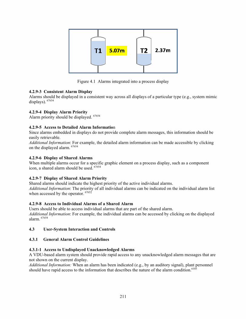
211
Figure 4.1 Alarms integrated into a process display 4.2.9-3 Consistent Alarm Display Alarms should be displayed in a consistent way across all displays of a particular type (e.g., system mimic displays). 67654 4.2.9-4 Display Alarm Priority Alarm priority should be displayed. 67654 4.2.9-5 Access to Detailed Alarm Information Since alarms embedded in displays do not provide complete alarm messages, this information should be easily retrievable. Additional Information: For example, the detailed alarm information can be made accessible by clicking on the displayed alarm. 67654 4.2.9-6 Display of Shared Alarms When multiple alarms occur for a specific graphic element on a process display, such as a component icon, a shared alarm should be used. 67654 4.2.9-7 Display of Shared Alarm Priority Shared alarms should indicate the highest priority of the active individual alarms. Additional Information: The priority of all individual alarms can be indicated on the individual alarm list when accessed by the operator. 67652 4.2.9-8 Access to Individual Alarms of a Shared Alarm Users should be able to access individual alarms that are part of the shared alarm. Additional Information: For example, the individual alarms can be accessed by clicking on the displayed alarm. 67654
4.3 User-System Interaction and Controls 4.3.1 General Alarm Control Guidelines 4.3.1-1 Access to Undisplayed Unacknowledged Alarms A VDU-based alarm system should provide rapid access to any unacknowledged alarm messages that are not shown on the current display. Additional Information: When an alarm has been indicated (e.g., by an auditory signal), plant personnel should have rapid access to the information that describes the nature of the alarm condition.6105
212
4.3.2 Silence Functions 4.3.2-1 Global Silence Capability It should be possible to silence the auditory alert for any alarm that can be seen from any set of alarm system controls in the main operating area. Additional Information: A global silence capability, together with separate silence and acknowledge capabilities, can be useful during high-alarm situations. It can allow the operator to silence many distracting alarms and then acknowledge these alarms at their respective panels. It is not necessary that silence capability be provided only where the specific alarm can be read, so long as the operator is made aware of all alarms that are being silenced. That is, the operator should not be able to silence alarms that cannot be visually detected from the global silence control. The primary purpose of the auditory signal is to alert the operator to a new alarm. Once alerted, the operator refers to visual indications of the specific alarm and its message. The auditory signal can rapidly become distracting and irritating to the operators. It should be possible to silence an audible cue from either a VDU or a tile-panel control station.0700, 6105 4.3.2-2 Manual Silencing Auditory signals should be silenced manually unless this interferes with other more critical actions. Additional Information: While manual silence is a generally desirable feature to get the operator’s attention, it may become distracting to have to manually silence all alarms under high-alarm conditions. Section 4.3.6, “Automatic Features,” addresses alarm system configuration changes made automatically.6105 4.3.3 Acknowledge Controls 4.3.3-1 Effect of Acknowledge Function An alarm acknowledgment function should cause the alarm’s visual coding to change from that indicating an unacknowledged alarm to a visually distinct “not cleared” state. Additional Information: For example, the acknowledge function might cause an alarm to change from flashing to steady. (See also Guideline 4.2.3-4, “Acknowledged Alarm Indication.”)0700 4.3.3-2 Acknowledgment Locations Acknowledgment should be possible only from locations where the alarm message can be read. Additional Information: If alarm information is available at multiple VDUs, then operators should be able to acknowledge the alarm from the VDU at which they are working. If alarm information is presented on a large control room overview display, operators should be able to acknowledge it from alarm control locations where it can be seen. This flexibility will minimize disruption caused by the alarm system interactions. It should not be possible to acknowledge alarms from locations where they cannot be read. If alarms can be acknowledged from multiple locations, then a means should be provided for ensuring that all operators for whom the alarm is important are aware that the alarm occurred. These means may include spoken, telephone, or computer-based communications among personnel.6105 4.3.3-3 Acknowledgment of Alarm Messages Non-SDCV alarms should only be acknowledged when the alarm message is on the screen. Additional Information: Alternatively, the acknowledgment action may display the alarm message.6105 4.3.4 Reset Functions 4.3.4-1 Effect of Reset Function The reset function should place an alarm in an unalarmed state after the condition has cleared. Additional Information: The reset function should silence any audible signal indicating clearance and should extinguish the light and return the alarm to an inactive state. Note that some alarms may have
213
automatic reset, when it is not necessary that the operators specifically know the reset condition.0700 4.3.4-2 Appropriate Use of Manual Reset A manual reset sequence should be used where it is important to explicitly inform users of a cleared condition that had once been deviant. Additional Information: An automatic reset sequence should not be used in this situation.6105 4.3.4-3 Appropriate Use of Automatic Reset An automatic reset sequence should be available where users have to respond to numerous alarms or where it is essential to quickly reset the system. Additional Information: A manual reset sequence should not be used in high-workload situations in which the time and attention required to reset the alarms may detract from other, more critical tasks.6105 4.3.4-4 Reset Function Location The reset function should be effective only from locations at which plant personnel know which alarm they are resetting.0700, 6105 4.3.5 Alarm Management 4.3.5-1 User-Selectable Alarm System Configuration If the alarm system provides user-selectable operational configurations, then these configuration changes should be coupled with an indication of the present configuration. Additional Information: Alarm systems allow users to select alternative functional configurations of the alarm system under some alarm situations, such as automatic silencing of auditory alerts for lower priority alarms under high-alarm conditions. Another example may be operator selection of an alarm message suppression mode in which low-priority messages are not presented through the alarm displays but may be accessed through operator action. It is important for the alarm system to inform the operators that a requested change in system configuration has been successfully achieved. In addition, a prominent display of the present configuration should be available.6105, 6684 4.3.5-2 Acknowledgment of Alarm System Configuration Changes Acknowledgment (or confirmation) should be required if a significant alarm system configuration change is to be made by user selection. Additional Information: Alarm systems allow users to select alternative functional configurations of the alarm system under some alarm situations. An example may be operator selection of an alarm message suppression mode in which low-priority messages are not presented through the alarm displays but may be accessed through operator action. It is important for the alarm system to inform the operators that a requested change in system configuration has been successfully achieved. In addition, a prominent display of the present configuration should be available.6105 4.3.5-3 User-Defined Alarms and Setpoints The alarm system may provide temporary, user-defined alarms and user-defined set points for specific conditions where such alarms are determined to be of assistance in selected evolutions (e.g., temporary alarms to support increased monitoring of a problem component, or at other times when the user wants to know of a parameter trend that is approaching a limit).6105 4.3.5-4 Interference of User-Defined Alarms and Setpoints with Existing Alarms User-defined alarms and setpoints should not override or interfere with the existing alarms and setpoints.6105
214
4.3.5-5 Indication of User-Defined Alarms and Setpoints The alarm system should provide a clear indication of user-defined alarms and setpoints, as distinct from the alarm and setpoints designed into the system.6105 4.3.5-6 Control of User-Defined Alarms and Setpoints The definition and removal of operator-defined system characteristics should be under administrative controls.6105 4.3.6 Automatic Features 4.3.6-1 Automated Alarm System Configuration If the alarm system automatically changes operational configurations under some alarm situations, then these configuration changes should be coupled with an alert to the user and an indication that the configuration has changed. Additional Information: Alarm systems may provide automated functions under some alarm situations, such as automatic silence of auditory alerts for lower priority alarms under high-alarm conditions. It is important that operators be notified of the change in system functioning. In addition, a prominent display should be available to remind operators of the current configuration of the system.6105 4.3.6-2 Acknowledgment of Automatic Alarm System Configuration Changes Acknowledgment (or confirmation) should be required if a significant alarm system configuration change is to be made automatically. Additional Information: Alarm systems may allow users to select alternative functional configurations of the alarm system under some alarm situations, such as automatic silencing of auditory alerts for lower priority alarms under high-alarm conditions. It is important for the alarm system to inform the users that a requested change in system configuration has been successfully achieved. In addition, a prominent display of the present configuration should be available.6105 4.3.6-3 Automatic Mode-Defined Setpoints The need for operator acknowledgment of system-generated setpoint changes based on plant modes should be evaluated on a case-by-case basis. Additional Information: Alarm systems may alter setpoints to minimize nuisance alarms. While such changes may be associated with well-understood, easily recognizable plant conditions, others may be less familiar and not readily understood by plant personnel. In the latter situation, plant personnel may misunderstand the alarm information because they do not realize the setpoints have changed. When this situation is of concern, confirmation of the change should be considered.6105 4.3.7 Control Devices 4.3.7-1 Separate Controls for Alarm Functions Separate controls should be provided for silence, acknowledgment, reset (acknowledging an alarm that has cleared and returning it to normal), and testing. Additional Information: A global silence capability, together with separate silence and acknowledge capabilities, can be useful during high-alarm situations by allowing the user to silence many distracting alarms and then acknowledge these alarms at their respective panels. A variety of controls is possible, such as pushbuttons, function keys, and onscreen controls.6105, 0700 4.3.7-2 Distinct Coding of Control Functions Alarm system controls should be distinctively coded for easy recognition. Additional Information: The controls should be distinguishable from each other, by touch and sight, to prevent accidental operation of the wrong control. Such techniques as color coding, color shading the

215
group of alarm controls, demarcating the group of alarm controls, or shape coding should be used.6105, 0700 4.3.7-3 Consistent Layout of Control Group Each set of alarm system controls should have the functions in the same relative locations. Additional Information: Consistent locations should be established for silence, acknowledge, reset, and test operating sequence controls.6105, 0700 4.3.7-4 Separate Controls for Tile and VDU Alarms If the alarm system contains both alarm tiles and VDU alarm displays, each should have its own set of controls.6105
4.3.7-5 Effect of Controls for Redundant Tile and VDU Alarms If alarm information is presented redundantly on tile and VDU displays, then alarm control by one device (i.e., either the VDU or tile-panel control station) should control the redundant alarm as well. Additional Information: For example, if a VDU alarm is acknowledged, the redundant tile alarm should be acknowledged as well.6105
4.3.7-6 Defeating Controls Alarm system control designs should not allow the controls to be altered or defeated. Additional Information: For example, some pushbuttons for alarm silencing and acknowledgement can be held down by inserting an object in the ring around the pushbutton. While the controls should be designed to prevent their being defeated, the system should be designed to minimize the desire to do so.6105, 0700 4.4 Reliability, Test, Maintenance, and Failure Indication Features 4.4.1 Reliability 4.4.1-1 Design for Reliability The alarm system should be designed so that no single failure will result in the loss of a large number of alarms. Additional Information: Also, the failure of a single alarm system component should not result in the loss of an individual alarm important to plant safety.6105 4.4.1-2 VDU Reliability Where alarms are presented on a VDU as the primary display, users should be able to access the alarms from more than one VDU. Additional Information: Failure of a single VDU should not prevent access to VDU-based alarm presentations at the main workstation. Alarm printer displays should not be the only backup to a VDU display.6105 4.4.1-3 Dual Light Bulbs Annunciator tile-type displays should be designed with dual light bulbs so that a single bulb failure will not interfere with detection of the alarm condition. Additional Information: Alarm system displays should be designed with a high level of reliability. In the case of annunciator tile displays, each tile should be illuminated by two or more lights to protect against a loss of indication caused by the failure of one.6105 4.4.1-4 Flasher Failure Mode In case of flasher failure, an unacknowledged alarm should assume a highly conspicuous state, such as a steady “on” (e.g., illuminated) state, rather than a less conspicuous state, such as “off.” Additional Information: While it is preferable in the case of a flasher failure for the associated alarm

216
element to remain on (e.g., illuminated) rather than off, a unique and highly conspicuous code is best. The code should be unique to prevent confusion between unacknowledged and acknowledged alarms. It should be salient to alert the operator to the malfunction of the alarm display system. In addition, other alerting mechanisms, such as warning messages, may be used to inform the operator of a malfunction in the alarm display system.0700, 6105 4.4.2 Test 4.4.2-1 Testing Capabilities Test controls should be available to initiate operability tests for all essential aspects of the alarm system (including processing logic, audible alarms, and visual alarm indications). Additional Information: For those portions of the alarm system (such as audible alarms and visual indications), the test capability should be simple and available to the operators. The more complex portions (such as sensor inputs and logic processing) should also be testable but by I&C technicians and engineers. Advanced alarm systems, having the capability for continuous, online, self-testing, may satisfy some of these recommendations.0700, 6105 4.4.2-2 Testing Requirement Periodic testing of the alarm system should be required and controlled by administrative procedure. Additional Information: Simple functional tests are normally required once per operating shift. Reliability analyses of the alarm system may be used to determine appropriate intervals and degree of testing to be performed on the alarm system.0700 4.4.3 Maintenance 4.4.3-1 Design for Maintainability The alarm system should be designed so that maintenance activities can be performed with minimal interference with the activities of the users. Additional Information: Desirable design features may include built-in test capabilities, modular components that can be rapidly removed and replaced, and rear access panels that prevent maintenance activities from obstructing the users’ view of controls and displays.6105 4.4.3-2 Tagged-Out Alarms Tagging out an alarm (taking it out of service) should require disabling of the associated visual and audio signals. Additional Information: A tagged-out alarm should never be lit or flashing and should never cause any audible device to sound.6105 4.4.3-3 Out-of-Service Alarm Indication Cues for prompt recognition of an out-of-service alarm should be designed into the system. Additional Information: Tagging out an alarm should not prevent its identification and should not obscure any other alarm or interfere with operations.6105, 0700 4.4.3-4 Extended Duration Illumination If an alarm tile must be “on” for an extended period during normal operations because of equipment repair or replacement, it should be (1) distinctively coded for positive recognition during this period, and (2) controlled by administrative procedures.0700 4.4.3-5 Tile Cover Replacement If a lamp replacement requires legend tile removal, there should be a way to ensure that the tile is replaced in the correct location.

217
Additional Information: The alarm element and the replacement task should be designed to prevent incorrect positioning of the cover, legend, or tile. For example, annunciator tiles might be permanently marked with a unique identifier specifying their position in the alarm window matrix. Alternatively, it might be administratively required that no more than one tile cover be removed from the matrix at a time.6105, 0700 4.4.3-6 Hazard Avoidance Lamp replacement should not pose an electrical shock hazard.0700 4.4.3-7 Aids for Alarm System Maintenance Aids should be provided, if needed, to assist personnel in performing alarm system maintenance. Additional Information: Aids include instructions and specialized tools. For example, aids may be needed to support changing the light bulbs in the alarm system.0700 4.4.4 Failure Indication 4.4.4-1 Alarm System Failure Indication Users should be given prompt indication of a failure of the alarm system or its major subcomponents.6105 4.5 Alarm Response Procedures 4.5-1 ARP Scope ARPs should be available for alarm conditions that require a response that affects the plant process control system or plant equipment. Additional Information: Minor alarms associated with data input errors or computer-space navigation errors may not require ARPs. In addition, other alarms, such as those in alarm systems that are separate from the main process alarm systems and require simple responses, may not need ARPs. In this latter case, the lack of ARPs should be specifically considered and justified. 6105, 6684 4.5-2 ARP Access Users should have immediate access to ARPs from the location at which the alarm messages are read. Additional Information: An operator should not be required to leave the location at which the alarm message is displayed to access ARP information. In a tile system, the identification and indexing of ARPs should be consistent with the method of identifying the alarm. The means used for identifying row and column locations of alarms should be distinct so that possible confusion of these identifiers is avoided. A computerized system may display the appropriate procedure for a given alarm on a VDU when the operator “selects” the alarm message.6105, 6684 4.5-3 ARP Content ARPs should contain the following information: a. the system or functional group to which the alarm belongs b. the exact alarm text or legend c. the alarm source (i.e., the sensor(s) sending the signal, processors and signal validation logic, and
the actuating device(s) for the alarm with a reference to a schematic diagram on which such devices can be found)
d. alarm setpoints e. priority f. potential underlying causes for the alarm (e.g., low water level, inadequate feed flow) g. required immediate actions, including actions that can be taken to confirm the existence of the
alarm condition

218
h. actions that occur automatically when the alarm occurs (and which should be verified as having
taken place) i. followup actions j. explanations of relevant alarm processing (e.g., comparisons and combinations of plant
parameters; alarm filtering and suppression; alarm setpoints that are conditional, such as setpoint values and time delays used to prevent the occurrence of nuisance alarms when a parameter oscillates in and out of the alarm range)
k. pertinent references Additional Information: Users should be given information (such as that associated with “alarm source” in the guideline) that they can use to confirm the existence of alarmed conditions.6105, 6684 4.5-4 Information Consistency with the HSI Information contained in the ARPs should be consistent with information on control boards, in the alarm system, in I&C procedures used to calibrate alarm setpoints, in controlling documents that determine setpoints (e.g., technical specifications and accident analyses), in piping and instrumentation diagrams (P&IDs), in emergency operating procedures, and in other plant procedures.6105 4.5-5 Presentation Consistency with the HSI The terminology, conventions, standards, and codes used to present the ARPs should be consistent with the rest of the HSI. Additional Information: The ARPs should use the same conventions, such as terminology for plant systems and equipment, identification codes for plant components and parameters, and measurement units, that are used in the main HSI displays and procedures. Defined values, such as alarm setpoints, should be consistent. In addition, information coding schemes used in the ARPs should be consistent with the rest of the HSI. For example, if graphical displays are used to present the ARPs, then coding conventions, such as symbols, icons, and color, should be consistent with the rest of the HSI, such as information presented in plant displays and computer-based systems for emergency operating procedures. For example, if color codes are used to indicate priority, it should have the same meaning across all displays of the HSI.6684 4.5-6 ARP Format The ARP format should do the following: a. highlight the ARP identifier on each page of the procedure b. highlight important items c. locate information categories in the same position on each page d. consistently present information throughout the ARP e. minimize the need for paging back and forth to obtain the information6105 4.6 Control-Display Integration and Layout 4.6-1 Display and Line of Sight Visible alarm indications should be located within about 60 degrees on either side of the direct line of sight of the user’s normal work position.6105 4.6-2 Location of Alarm System Displays and Controls Alarm displays and controls should be located so that the display can be read while operating the controls.6105
219
4.6-3 Location of First-Out Alarms First-out displays should be located at the main workstation for the system, at a plant overview display visible to the crew, or both.0700 4.6-4 Consistent Ordering The ordering (e.g., left-to-right positioning) of displayed alarm groups should be consistent with the ordering of displays and controls of related plant systems and components.6105 4.6-5 Location for Prompt Response Alarm displays and controls should be arranged and located such that those in the control room who must respond to an alarm can access the alarm information in sufficient time to respond adequately.6105 4.6-6 Location for Access to Process Controls and Displays Visual alarm panels should be located near the controls and displays that are required for corrective or diagnostic action in response to the alarm. Additional Information: If displays and controls associated with an alarm are on different panel segments, the alarm displays should be located near the process display segment. If they are presented on a VDU, easy access to supporting controls and displays should be provided in the display.6105, 6684, 0700 4.6-7 Interference from Nearby Lights Indicator lights or other nonalarm illuminated displays should not be located so close to alarm displays that they could be mistaken for an alarm or mask an alarm.6105 4.7 Integration with Other HSI Elements 4.7-1 Consistency with the Main HSI The alarm system HSI should be consistent with the standards and conventions used for the HSIs for other displays and controls in the control room. Additional Information: The alarm system should use the same conventions, such as symbols, icons, acronyms, coding, and measurement units, that the main HSI displays and procedures use. While some minor differences may exist, the alarm system should never use a display feature, such as coding, in a way that is different from or conflicts with other HSIs. For example, if color is used to code priority, it should have the same meaning in the alarm system as in the process displays.6105 4.7-2 Consistency with Emergency Operating Procedures The alarm system HSI should be consistent with the standards, conventions, and terminology used in the plant emergency operating procedures. Additional Information: The alarm system should use the same conventions, such as terminology for plant systems and equipment, identification codes for plant components and parameters, and measurement units, that the main HSI displays and procedures use. Defined values, such as alarm setpoints, should be consistent. In addition, if the procedures use coding to present information, such as in graphic displays of a computer-based procedure system, then the alarm system should use the same conventions, such as symbols, icons, and coding. For example, if color is used to code priority, it should have the same meaning in the alarm system as in the displays of a computer-based emergency operating procedure.6684 4.7-3 Conformance to HSI Design Review Guidelines Alarm system elements (e.g., displays and controls) should conform to general HSI guidelines as well as alarm system guidelines. Additional Information: While the alarm system guidelines take precedence over other more general human factors engineering guidelines, it should be kept in mind that the alarm system is a part of the overall HSI. As such, it should conform to the same guidelines for general display and control design. For

220
example, if the alarm system uses a touch screen interface for operator input and query of the system, the review guidelines for touchscreens (Section 3.2.4, “Touch Screens, Light Pens, and Graphic Tablets”) should be used to evaluate that aspect of the interface. As another example, if the alarm displays are integrated into P&ID VDU displays, the P&ID aspect to the display, such as icons and symbols, should be evaluated using Section 1.2.8, “Mimics and Diagrams,” and Section 1.3.4, “Icons and Symbols.” In case of overlap or conflict in guidelines when reviewing the alarm system, the guidelines for alarm systems take precedence.6105

221
5 SAFETY PARAMETER DISPLAY SYSTEM
Safety Parameter Display System Characterization The primary purpose of the safety parameter display system (SPDS) is to present information that personnel can use to determine the safety status of the plant during normal, abnormal, and emergency conditions, including severe accidents, and to determine whether conditions warrant corrective actions by operators to avoid or mitigate a degraded core. Personnel can determine the plant’s safety status by monitoring information about the plant’s safety functions1 and their associated parameters.2 NUREG-0711, “Human Factors Engineering Program Review Model,” issued November 2012, defines “safety functions” as those functions serving to verify high-level safety objectives and often are defined in terms of a boundary or entity important to ensuring the plant’s integrity and to preventing the release of radioactive materials. A typical safety function is “reactivity control.” A high-level objective, such as impeding the release of radioactive material to the environment, is one that designers strive to achieve through the design of the plant and that plant personnel endeavor to attain by properly operating the plant. The function often is described without reference to specific plant systems and components, or the level of human and machine intervention needed to carry out this action. Functions often are accomplished through some combination of lower level functions, such as “reactor trip.” This definition encompasses both accident and severe accident conditions, per NUREG-0737, “Clarification of TMI Action Plan Requirements,” Supplement 1, issued January 1983 (NRC, 1983, p. 8). References in this section to specific safety functions and parameters are provided as examples only. A licensee or applicant should identify the safety functions and parameters for a specific design, and the staff of the U.S. Nuclear Regulatory Commission (NRC) should review them using the guidance in NUREG-0711, Section 8.4.4.2, “Main Control Room,” Review Criterion 1, “SPDS” (safety parameter display system). Note that NUREG-0696, Functional Criteria for Emergency Response Facilities,” issued February 1981 (NRC, 1981a), specifies that an SPDS be in the main control room, technical support center (TSC), and emergency operations facility (EOF). The NRC staff uses the guidance in this section of NUREG-0700 to review a licensee’s or applicant’s SPDS. The review criteria that ensure that the SPDS conforms to accepted human factors engineering (HFE) principles are divided into the following sections: • Information Display • Reliability, Test, Maintenance, and Failure Indication Features • Integration with Other Human-System Interface (HSI) Elements The following discussion is an overview of each of these subsections, followed by review criteria. Title 10 of the Code of Federal Regulations (10 CFR) 50.34(f)(2)(iv) requires the availability of an SPDS:
Provide a plant safety parameter display console that will display to operators a minimum set of parameters defining the safety status of the plant, capable of displaying a full range
1 Safety functions are sometimes referred to as “critical safety functions” (e.g., Institute of Electrical and Electronics
Engineers (IEEE)-497-2002 (IEEE, 2002). 2 This section uses the term “parameters” rather than “variables” to maintain consistency with SPDS source documents.
Other documents (e.g., IEEE-497-200 and Regulatory Guide (RG) 1.97, “Criteria for Accident Monitoring Instrumentation for Nuclear Power Plants,” Revision 4, issued 2006 (NRC, 2006)) use the term “variables.” For purposes of discussing SPDS in this section, the two terms are interchangeable.

222
of important plant parameters and data trends on demand, and capable of indicating when process limits are being approached or exceeded.
The NRC published SPDS review guidance in NUREG-0737 (Supplement 1) (NRC, 1983), NUREG-0696 (NRC, 1981a), and NUREG-0835, “Human Factors Acceptance Criteria for the Safety Display System," issued 1981 (NRC, 1981b). The staff then followed up with additional clarifications in NUREG/CR-4797, “Progress Reviews of Six Safety Parameter Display Systems,” issued 1986 (NRC, 1986), and NUREG-1342, “A Status Report Regarding Industry Implementation of Safety Parameter Display System,” issued April 1989 (Lapinsky et al., 1989). Because this section of NUREG-0700 consolidates the HFE review guidance on SPDS, NRC reviewers do not have to consult all the documents listed above to review a licensee’s or applicant’s SPDS. References to the original documents are shown in the source field of each guideline, and reviewers can consult these documents if additional information and clarifications are needed. Four additional considerations when using this guidance are as follows: (1) The guidance in the original SPDS source documents reflects conventional light-water reactor (LWR) designs. Therefore, the NRC modified the guidance to make it applicable to other reactor types (i.e., high-temperature, gas-cooled reactors (HTGR) and liquid-metal reactors (LMRs), in addition to pressurized-water reactors (PWRs) and boiling-water reactors (BWRs)).
(2) The original SPDS review criteria were based on the concept of SPDS being a standalone system. When SPDS was first required, plants did not have effective means of monitoring safety functions and key safety parameters. SPDS provided that capability. SPDS continues to be an important aspect of new control room designs. Unlike the backfit of the SPDS function into existing control rooms as standalone consoles, new control rooms integrate SPDS into the overall HSI design. Thus, the SPDS function does not need its own unique console or display devices. However, new control rooms provide significantly more information for personnel to deal with and usually require operators to navigate through displays to access it. Thus, the need to provide SPDS information in a concise, easily understood manner that is consistent with the guidance in this section is just as important as for older control rooms. The “Additional Information” sections of the guidelines include an interpretation of how the SPDS functionality may be applied in new plants.
(3) Many of the review criteria presented in the SPDS source documents reflect good HFE design practices as they apply to SPDS. Therefore, individual guidelines sometimes duplicate the HSI design review guidelines presented elsewhere in this document. The “Additional Information” sections provide cross-references. Reviewers can consult these guidelines for clarification, if needed.
(4) This section contains guidance specifically developed for the SPDS. However, it does not address all characteristics of the SPDS design. For example, the guidance in this section does not address the following:
• detailed design of specific display formats, such as for trend graphs • use of highlighting features, such as color • properties of alerting features, such as prompts and alarms • navigation features, such as links to lower level safety parameter displays

223
The reviewer should use the detailed guidance in other sections of NUREG-0700 to review these aspects of a licensee’s or applicant’s SPDS design. The guidelines in this section, together with the pertinent guidance in other NUREG-0700 sections, will provide an evaluation consistent with NUREG-0737, Supplement 1, Requirement 4.1(e): “The SPDS display shall be designed to incorporate accepted human factors principles so that the displayed information can be readily perceived and comprehended by SPDS users.”
The following discussion includes an overview of each of the subsections. Information Display The information presented by these monitoring systems includes primarily parameters and status indications of safety functions. Parameters are physical properties of the plant that are expressed mathematically, such as “temperature” and “level.” Parameters may be directly sensed (based on sensor measurement), derived (information that could be directly sensed but instead is derived from the measurements of other sensors), and synthetic (information that cannot be sensed by instrumentation but is computed mathematically from other information (e.g., rate of change and the overall status of a safety function). Status indications provide status information, such as “valve closed” and “reactivity control off-normal.” The SPDS can provide other types of information, as well (e.g., plant mode). Important information presentation characteristics include the organization of related information, ease of access, readability, conciseness, the plant mode sensitivity, the data sampling rate, the display’s accuracy, the indication of magnitudes and trends for parameters, and alerts to changing or important information. Section 5.1 includes guidelines for reviewing these display characteristics. The devices used to display SPDS information include conventional or computer-based devices. Conventional display devices include meters, light indicators, numeric readout displays, and plotters. Computer-based display devices include cathode ray tubes (CRTs), flat panels, and group-view display systems. These devices may have single or multiple display functions. A single-function device presents information in a fixed format. Examples include an indicator that presents a single parameter and a visual display unit (VDU) that presents a single page containing a set of parameters. A multiple-function device contains a set of display pages through which the user navigates to access desired information. Reliability, Test, Maintenance, and Failure Indication Reliability addresses the resistance of the system to failures. It affects the degree of trust that operators have regarding the displayed information and whether the system will continue to operate correctly when needed. Failure indications address the ways in which the user is informed of the presence of potential failures or malfunctions in the system. These indications aid the user in identifying and diagnosing failures. Data validation techniques are used in plant instrumentation and control (I&C) systems to assess the validity of plant data by comparing the data from different sources. Data that pass the test are said to be valid (i.e., of reliable quality), while data that fail are determined to be invalid (i.e., not reliable and possibly indicative of a system malfunction). Data that cannot be tested, such as when processors or redundant data are not available, are said to be unvalidated (i.e., of unknown quality). Analytical redundancy refers to one method for testing the validity of data. It is the comparison of measured parameters, by mathematical models based upon known physical relationships among parameters. Another method of data validation is the direct comparison of values from redundant sensors. Section 5.2 gives guidelines for reliability, test, maintenance, and failure indication features.
224
Integration with Other HSI Elements This characteristic addresses the consistency and compatibility of the SPDS with the rest of the HSI. Because SPDS is used together with other displays, its consistency and compatibility with them is an important review consideration. This document’s Sections 1, 2, and 3, provide an extensive set of design review guidelines for information display, user-system interaction, and process control and input devices, respectively, that can be used to help ensure consistency and compatibility. In addition, the physical integration of the SPDS with the rest of the HSI is an important review consideration because a well-integrated system can be readily accessed and does not interfere with the use of other portions of the HSI. Section 5.3 provides guidelines for the physical integration of the SPDS with the rest of the HSIs, whether in the main control room, TSC, or EOF. A comprehensive review of an SPDS design should include how degraded HSI and I&C conditions affect it. Degraded conditions can have significant impacts on proper HSI functioning. Although this section contains some guidance for reviewing this aspect of SPDS functioning, Section 14 provides additional guidance for reviewing degraded HSI and I&C conditions. Bibliography Source Code Documents 0737 U.S. Nuclear Regulatory Commission (1983). Clarification of TMI Action Plan Requirements
(NUREG-0737 and supplements). Washington, DC: U.S. Nuclear Regulatory Commission. 0835 U.S. Nuclear Regulatory Commission (1981b). Human Factors Acceptance Criteria for the
Safety Parameter Display System (NUREG-0835). Washington, DC: U. S. Nuclear Regulatory Commission.
1342 Lapinsky, G., Eckenrode, R., Goodman, P., and Correia, R. (1989). A Status Report Regarding
Industry Implementation of Safety Parameter Display System (NUREG-1342). Washington, DC: U. S. Nuclear Regulatory Commission.
67652 O’Hara, J., Anderson, T., and Higgins, J. (2014). Development of NUREG-0700 Review
Guidance for Safety Parameter Display Systems (BNL Technical Report No. 67652). Upton, NY: Brookhaven National Laboratory.
Other References AREVA (2011). U.S. EPR Final Safety Analysis Report, Chapter 6, “Engineered Safety Features,” and Chapter 19, “Probabilistic Risk Assessment and Severe Accident Evaluation.” Washington, DC: U.S. Nuclear Regulatory Commission. Argonne National Laboratory (2005). Small Modular Fast Reactor Design Description (Report ANL-SMFR-1). Argonne, IL: Argonne National Laboratory. Institute of Electrical and Electronics Engineers (2002). IEEE Standard Criteria for Accident Monitoring Instrumentation for Nuclear Power Generating Stations (IEEE Std. 497-2002). New York: Institute of Electrical and Electronics Engineers

225
Idaho National Laboratory (2011). Modular HTGR Safety Basis and Approach (Report INL/EXT-1 1-22708). Idaho Falls, ID: Idaho National Laboratory. O'Hara, J., Higgins, J., Fleger, S., and Pieringer, P. (2012). Human Factors Engineering Program Review Model (NUREG-0711, Rev. 3). Washington, DC: U.S. Nuclear Regulatory Commission. U.S. Nuclear Regulatory Commission (2011). ESBWR Design Certification Final Safety Evaluation Report, Chapter 19, “Probabilistic Risk Assessment and Severe Accident Evaluation.” http://pbadupws.nrc.gov/docs/ML1034/ML103470210.html U.S. Nuclear Regulatory Commission (2006). Criteria for Accident Monitoring Instrumentation for Nuclear Power Plants (RG 1.97, Rev. 4). Washington, DC: U.S. Nuclear Regulatory Commission. U.S. Nuclear Regulatory Commission (1986). Progress Reviews of Six Safety Parameter Display Systems (NUREG/CR-4797). Washington, DC: U.S. Nuclear Regulatory Commission. U.S. Nuclear Regulatory Commission (1981a). Functional Criteria for Emergency Response Facilities (NUREG-0696). Washington, DC: U.S. Nuclear Regulatory Commission. U.S. Nuclear Regulatory Commission (1981c). Human System Interface Design Review Guideline (NUREG-0700, Rev. 0). Washington, DC: U.S. Nuclear Regulatory Commission . U.S. Nuclear Regulatory Commission (1980). NRC Action Plan Developed as a Result of the TMI-2 Accident (NUREG-0660). Washington, DC: U.S. Nuclear Regulatory Commission. 5.1 Information Display 5.1-1 Display of Safety Functions and Parameters The SPDS should display all safety functions and the minimum set of parameters necessary to monitor them. Additional Information: In 10 CFR 50.34(f)(2)(iv), the SPDS “will display to operators a minimum set of parameters defining the safety status of the plant, capable of displaying a full range of important plant parameters and data trends on demand.” Parameters may be directly sensed (based on sensor measurement), derived (information that could be directly sensed, but instead is derived from the measurements of other sensors), or synthetic (information that cannot be sensed by instrumentation but is computed mathematically from other information (e.g., rate of change and the overall status of a safety function). For a specific design, the licensee or applicant should identify the safety functions and the parameters used to monitor them (see NUREG-0711, Section 8.4.4.2, “Main Control Room,” Review Criterion 1, SPDS). Table 5.1 presents examples of safety functions and parameters for different plant types. These examples are for illustration only. The licensee or applicant should identify the specific parameters. These parameters are essentially the same as the Type B variables of IEEE Std. 497-2002, as endorsed by RG 1.97, Revision 4. Type B variables are the variables that provide primary information to the control room operators to assess the plant’s critical safety functions. To meet the SPDS function of assessing the plant’s safety status, it is important that the parameters be measured across the full range of their expected variation. The SPDS should allow for easy navigation to screens showing the output of the accident monitoring instrumentation specified in IEEE Std. 497-2002, as endorsed by RG 1.97, Revision 4. The SPDS should indicate symptoms that precede core damage and post-core damage severe accident symptoms, such as the symptoms of core melt, vessel breach, and containment base mat degradation. Related to the post-core damage symptoms, new plants may have functions and systems to address this phase of an accident

226
(e.g., a safety function of “Containment Basemat/Core Catcher Cooling”). Current plants do not have systems to display post-core damage systems in SPDS; however, including them is fully consistent with 10 CFR 50.34(f)(2)(xix), which states, “Provide instrumentation adequate for monitoring plant conditions following an accident that includes core damage,” and the SPDS guidance in NUREG-0737, Supplement 1. Parameters associated with severe accidents will assist operators in verifying mitigation by such systems and in taking prescribed operator actions. Guideline 1.1-11, “Display of Goal Status,” contains additional information. 0737, 0835, 1342, 67652
Table 5.1 Examples of safety functions (in italics) and parameters for a variety of plant types
Pressurized Water Reactors (PWRs), Boiling Water Reactors (BWRs), High-Temperature, Gas-Cooled Reactors (HTGRs), and Liquid-Metal Reactors (LMRs)
PWRs BWRs HTGRs LMRs
Reactivity Control Reactivity Control Reactivity Control Reactivity Control • Power Range • Average Power
Range • Neutron Flux • Neutron Flux
• Intermediate Range • Source Range • Source Range
Reactor Core Cooling and Heat Removal from the
Primary System
Reactor Core Cooling and Heat Removal from the
Primary System
Reactor Core Cooling and Heat Removal from the
Primary System
Reactor Core Cooling and Heat Removal from the
Primary System • RCS Level • RPV Water Level • Fuel Inlet/Outlet
Temperature • Core Exit
Temperature • Subcooling Margin • Drywell Temperature • Primary System
Pressure • Primary Sodium
Temperature • Hot Leg Temperature • Primary System Flow • Primary Sodium Level • Cold Leg
Temperature • Steam Generator
Pressure • ACS/IRACS Flow
• Core Exit Temperature
• Steam Generator Level
• Primary Sodium Flow Rate
• Steam Generator Pressure
• Intermediate Heat Exchanger (IHX) Flow Rate
• RHR (DHR) Flow • IHX Temperature Reactor Coolant System
Integrity Reactor Coolant System
Integrity Chemical Attack Control Reactor Coolant System
Integrity • RCS Pressure • RPV Pressure • Primary System
Moisture Concentration
• Reactor Vessel Cover Gas Pressure
• Cold Leg Temperature
• Primary System Gas Concentration
• RVACS Flow
• Containment Sump Level
• Primary System Pressure
• Sodium Leak Rate
• Steam Generator Pressure
• Primary System Radiation Level
• Containment Cell Temperature
• Steam Generator Level
• Reactor Building Radiation Level
• Containment Cell Pressure
• Steam Generator Blowdown Radiation Level
• Site Periphery Radiation Level
Containment Conditions Containment Conditions Containment Conditions • Containment
Pressure • Drywell Pressure • RVACS Flow
• Containment Isolation Status
• Drywell Temperature • Containment Radiation Level
• Containment Hydrogen
• Suppression Pool Temperature
• Containment Cell Temperature
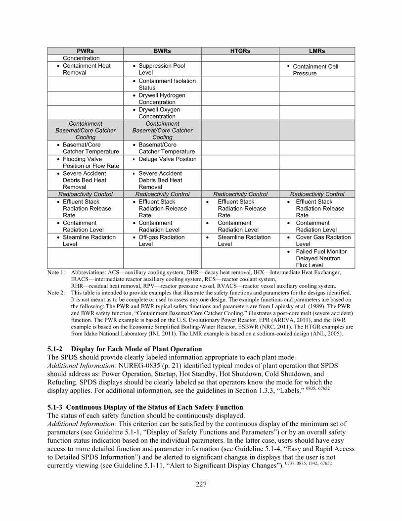
227
PWRs BWRs HTGRs LMRs Concentration
• Containment Heat Removal
• Suppression Pool Level
• Containment Cell Pressure
• Containment Isolation Status
• Drywell Hydrogen Concentration
• Drywell Oxygen Concentration
Containment Basemat/Core Catcher
Cooling
Containment Basemat/Core Catcher
Cooling
• Basemat/Core Catcher Temperature
• Basemat/Core Catcher Temperature
• Flooding Valve Position or Flow Rate
• Deluge Valve Position
• Severe Accident Debris Bed Heat Removal
• Severe Accident Debris Bed Heat Removal
Radioactivity Control Radioactivity Control Radioactivity Control Radioactivity Control • Effluent Stack
Radiation Release Rate
• Effluent Stack Radiation Release Rate
• Effluent Stack Radiation Release Rate
• Effluent Stack Radiation Release Rate
• Containment Radiation Level
• Containment Radiation Level
• Containment Radiation Level
• Containment Radiation Level
• Steamline Radiation Level
• Off-gas Radiation Level
• Steamline Radiation Level
• Cover Gas Radiation Level
• Failed Fuel Monitor Delayed Neutron Flux Level
Note 1: Abbreviations: ACS—auxiliary cooling system, DHR—decay heat removal, IHX—Intermediate Heat Exchanger, IRACS—intermediate reactor auxiliary cooling system, RCS—reactor coolant system, RHR—residual heat removal, RPV—reactor pressure vessel, RVACS—reactor vessel auxiliary cooling system.
Note 2: This table is intended to provide examples that illustrate the safety functions and parameters for the designs identified. It is not meant as to be complete or used to assess any one design. The example functions and parameters are based on the following: The PWR and BWR typical safety functions and parameters are from Lapinsky et al. (1989). The PWR and BWR safety function, “Containment Basemat/Core Catcher Cooling,” illustrates a post-core melt (severe accident) function. The PWR example is based on the U.S. Evolutionary Power Reactor, EPR (AREVA, 2011), and the BWR example is based on the Economic Simplified Boiling-Water Reactor, ESBWR (NRC, 2011). The HTGR examples are from Idaho National Laboratory (INL 2011). The LMR example is based on a sodium-cooled design (ANL, 2005).
5.1-2 Display for Each Mode of Plant Operation The SPDS should provide clearly labeled information appropriate to each plant mode. Additional Information: NUREG-0835 (p. 21) identified typical modes of plant operation that SPDS should address as: Power Operation, Startup, Hot Standby, Hot Shutdown, Cold Shutdown, and Refueling. SPDS displays should be clearly labeled so that operators know the mode for which the display applies. For additional information, see the guidelines in Section 1.3.3, “Labels.” 0835, 67652 5.1-3 Continuous Display of the Status of Each Safety Function The status of each safety function should be continuously displayed. Additional Information: This criterion can be satisfied by the continuous display of the minimum set of parameters (see Guideline 5.1-1, “Display of Safety Functions and Parameters”) or by an overall safety function status indication based on the individual parameters. In the latter case, users should have easy access to more detailed function and parameter information (see Guideline 5.1-4, “Easy and Rapid Access to Detailed SPDS Information”) and be alerted to significant changes in displays that the user is not currently viewing (see Guideline 5.1-11, “Alert to Significant Display Changes”). 0737, 0835, 1342, 67652

228
5.1-4 Easy and Rapid Access to Detailed SPDS Information If SPDS information is presented as part of a display hierarchy, users should have easy and rapid access to all displays within the hierarchy. Additional Information: An example is a hierarchic network of displays from which the user can access more detailed, lower level parameter displays using navigation links provided in each display. SPDS response times to user requests should be consistent with Guideline 2.4.3-1, “Response Time Appropriate to Transaction.” Access to lower level displays should not interfere with the continuous display of safety function status. Guidelines 1.1-24, “Navigational Links to Related Information”; 1.1-50, “Display Area”; and 1.1-51, “Predefined Displays,” contain additional information. See also Section 2, “User-Interface Interaction and Management.” 1342, 67652 5.1-5 Readable SPDS displays should be readable from user work positions and workstations. Additional Information: User categories include shift supervisor, reactor operator, and shift technical advisor. Guideline 1.1-33, “Readability Conditions,” contains additional information. 0737, 0835, 1342, 67652 5.1-6 Concise Presentation SPDS information should be displayed in a concise format. Additional Information: The display format should support users in comparing data from across related plant functions and assessing the safety status of the plant. A concise format might be achieved by presenting a group of parameters on a single display or by arranging a set of displays (e.g., separate indicators) in a single location. Guideline 1.1-50, “Display Area,” contains additional information. 0737,
0835, 1342, 67652 5.1-7 Data Sampling Rate SPDS information should be sampled at a rate that ensures that no meaningful data needed by operators, or trends in that data, will be missed. Additional Information: In modern digital I&C systems, information from sensors and other sources is often stored and updated in a database for use by plant and control room systems, such as SPDS, computer-based procedures, and displays. The intent of this guideline is to ensure that the SPDS accesses this information and updates at a rate consistent with the operator’s information needs. NUREG-1342 (Lapinsky et al., 1989) provides an example. RCS pressure requires data resolution in terms of seconds, while certain radiation levels can be sampled every 30 seconds, 60 seconds, or several minutes. Section 1.4, “Data Update Rate,” contains additional information. 1342, 67652 5.1-8 Display Update Rate SPDS information should be updated often enough to ensure that changes in plant status will not be masked or lost. Additional Information: The update rate should be consistent with, and sufficient to represent, expected variations in plant safety parameters. 1342, 67652 5.1-9 Information Accuracy SPDS information should be displayed with sufficient accuracy for the user to discriminate between normal conditions and those affecting plant safety status. Additional Information: Guideline 1.4-8, “Accuracy,” contains additional information. 0835, 67652 5.1-10 Magnitudes and Trends of Parameters The SPDS should provide magnitudes and trends for parameters. Additional Information: In 10 CFR 50.34(f)(2)(iv), the regulation states that the SPDS will provide “data trends on demand.” Trends should be displayed with sufficient resolution in time and magnitude to ensure

229
that rapidly changing parameters can be observed and accurately interpreted. The time history should cover enough time and be accurate enough to depict the onset and development of conditions that vary from preceding normal operating conditions. Section 1.2.5, “Graphs,” contains additional information. 0835, 1342, 67652 5.1-11 Alert to Significant Display Changes The SPDS should alert users to changes in information that require their attention but are not currently being viewed. Additional Information: An operator may be looking at a detailed display when there is a significant change in a higher-level display. SPDS should alert the operator to such a change. Guidelines 1.1-10, “Alert to Higher Level Displays,” and 1.1-38, “Distinctive Coding of Critical Information,” contain additional information. 0835, 67652 5.1-12 Alerts for Conditions Requiring Action The SPDS should provide perceptual (audible and visual) cues to alert users to abnormal operational conditions that potentially warrant corrective action. Additional Information: In 10 CFR 50.34(f)(2)(iv), the regulation states that the SPDS will indicate “when process limits are being approached or exceeded.” When SPDS was first required, plants did not have effective means of monitoring safety functions and key safety parameters. SPDS provided that capability. In new plants, the HSIs are much more integrated and alarm systems much better designed. The review of this criterion should consider (1) the design of the alarm system to provide alerts to conditions requiring personnel action that are addressed by this guideline, and (2) the degree of integration of alarm functionality and safety function monitoring (e.g., the integration of alarms into SPDS displays). Section 4, “Alarms”; especially, Section 4.2.9, “Alarm Integrated into Other Displays,” has additional information.0835, 67652 5.1-13 Rapid and Reliable Recognition of Safety Status Change The display should incorporate features that allow users to quickly and accurately comprehend a change in safety status. Additional Information: These displays should incorporate accepted HFE principles to ensure change detection. For example, display features can be used that noticeably change when an unsafe condition is approached. Thus, color coding provides a high-level representation of overall function status, such as using green to indicate the function is acceptable, yellow to indicate that function is being challenged, and red to indicate the function has been lost and needs to be recovered. Such a design feature would enable operators to detect the status of all safety function at a glance. SPDS should support “Status at a Glance” functionality; see Guideline 1.1-14, “Status at a Glance.”0737, 0835, 1342, 67652 5.2 Reliability, Test, Maintenance, and Failure Indication 5.2-1 SPDS Reliability The SPDS software, processing, and display equipment should be reliable. Additional Information: The evaluation should involve I&C reviewers who verify that SPDS hardware and software meet the guidance in Standard Review Plan (SRP) NUREG-0800, Chapter 7, “Instrumentation and Controls.” For this review, SPDS should be treated as nonsafety related, with regulatory treatment of nonsafety system controls applied (see SRP Chapter 19.3, “Regulatory Treatment of Non-Safety Systems for Passive Advanced Light Water Reactors”).1342, 67652 5.2-2 Indication of SPDS Degradations and Failures SPDS should provide an indication of system degradations and failures. Additional Information: For additional information, see Section 14.2, “HSI Response to I&C System Changes.”1342, 67652

230
5.2-3 Data Validation SPDS data should be validated in real time. Additional Information: The SPDS should not give false indications of plant status; therefore, validation methods should be used to ensure high data quality and accuracy. Lack of validation places the burden of identifying valid readings on the operator. For additional information, see Guideline 14.3-2, “Data Validation.” 0835, 1342, 67652 5.2-4 Display of Information Validation for Plant Parameters The status of SPDS information should be displayed to the user with an appropriate quality indicator (e.g., valid, invalid, or unvalidated; or a numerical estimate). Additional Information: Operators should also have available (e.g., on a separate display page) the individual sensor readings, so they can pinpoint an indicated problem, if the validation fails.0835, 67652 5.3 Integration with Other HSI Elements 5.4-1 Visual Interference with Other Controls and Displays The SPDS should not interfere with visual access to other control room operating systems or with displays that are important to the safe operation of the plant. 0835, 1342, 67652 5.4-2 Interference with Crew Movement The location of SPDS equipment should not interfere with the normal movement of the control room crew. 0835,1342, 67652 5.4-3 Labeling SPDS displays should be labeled and readily distinguished from other displays.0835, 67652

231
6 GROUP-VIEW DISPLAY SYSTEM
Group-View Display System Characterization Group-view display systems allow multiple individuals to simultaneously view the same information when they are in the control room (CR) or distributed throughout the plant. The most important characteristic of a group-view display is that it supports team performance, not what type of device is used to implement the display. In conventional CRs, group-view displays have traditionally used large-screen displays that enable multiple individuals to refer to the same information and allow individuals to move about the CR while still viewing the information. They can also reduce distractions that might otherwise occur if the information needed by multiple individuals is located at the workstation of one individual. Configurations other than large-screen display devices are also used, such as small-screen display devices that are conveniently located for access by multiple individuals (i.e., walkup display devices). Conventional CRs have specific characteristics that have evolved over many years of design that contribute to crew performance. They typically feature hardwired controls and displays (and perhaps a lesser number of computer-based controls and displays) that are installed on large control panels that are shared by the crew members. Because they have fixed locations on control panels, access typically does not require unusual display-space navigation skills. Personnel who wish to use the same control or display tend to be aware of each other’s intent and actions because they must share the physical devices. In addition, supervisors and other operators can often understand much about an individual’s activities (e.g., which procedure step is being performed) by observing the operator’s position at the control panels, which contain spatially fixed controls and displays. Some of these positive characteristics of conventional CRs may be lost in CRs with computer-based workstations, resulting in the following types of problems: • Difficulty maintaining awareness of overall plant status—Narrowing of attention to local
problems at the expense of overall awareness has long been a problem in nuclear power plants (NPPs). This problem may be aggravated in computer-based CRs by the fact that only a portion of the total plant information is visible at one time through the limited viewing area of an information display screen.
• Difficulty and time delay associated with accessing computer-based controls and displays—
Problems may result because controls and displays must be retrieved through navigation of the computer display space.
• Difficulty maintaining awareness of crew member actions—Operator actions performed in a
computer-based workstation may be less identifiable when compared with actions performed at a conventional control panel. In addition, because a single control could have multiple locations in the computer display space, it may be possible for multiple operators to perform tasks involving the same control without being fully aware of each other’s specific control actions and intentions.
• Difficulty communicating—Expressing ideas through face-to-face interactions using gestures or
verbal communication is important to crew performance. This may be difficult in a computer-based CR because of physical separation or isolation. This problem may be further aggravated by the fact that operators have individual views of the display system and may not be

232
viewing the same portion (e.g., display page) of the display system when they attempt to collaborate.
Functional Characteristics The overall purpose of a group-view display system can vary from design to design. The specific purpose of the system provides a basis for identifying and assessing the relevance and appropriateness of the functional capabilities and design features of a group-view display system. Some considerations to be addressed include the intended users of the system, the physical locations to be covered, the conditions under which the system is to be used (e.g., normal operations versus emergencies), and the types of support the group-view display system provides to personnel. Group-view displays can include the following functions: • Provide an overview or high-level summary of the plant status (see Section 6.1.2).
• Direct operators to additional information from other portions of the human-system interface
(HSI) by providing automatic retrieval of required information or cues to the operator to assist manual retrieval (see Section 6.1.3).
• Support crew coordination and awareness of each other’s activities (see Section 6.1.4).
• Support personnel communication and collaboration for tasks such as diagnosing the cause of a
process failure or performing a multiperson control task that may require discussions among personnel to coordinate information, diagnose problems, and plan corrective actions. To accomplish this, a group-view display should provide information that other operators can see, discuss, and use. Verbal communication and gestures, such as pointing, are important means for communicating ideas. When operators are physically present at the same display device, communication may take the form of natural talking and gesturing. However, when operators cannot be physically present at the same display device, this type of communication may take the form of computer-based interaction (see Section 6.1.5).
User-System Interaction The specific characteristics of group-view displays that support user interaction may be considered in two categories: (1) support for an individual’s interaction with a group-view display device and (2) support for shared use of the group-view display device among multiple individuals. Each is described below. Features that support individual interaction allow a user to access, and possibly manipulate, information presented on the group-view display. An important consideration is whether the group-view display is a standalone system or is coordinated with the controls and displays. The following are some examples: • Coordinated displays—The user can select options from the group-view display and the chosen
items appear on a display in the user’s work area.
• Coordinated controls—The user can operate both the group-view display and a display in the user’s work area with the same control device, such as the same keyboard or mouse.
Features for shared use allow multiple users to interact with the display. Features that manage users’ access to the group-view display system are important for minimizing conflict. For example, if one crew member changes the information content of the display to suit personal needs, the needs of the other crew

233
members may not be met. Some interaction considerations that are important to a human factors engineering (HFE) design review include the following: • User access—Sequential user access allows one user to interact with the system at a time. This
may require some sort of gate-keeping function to help users “take turns.” Concurrent access allows multiple individuals to use the system at the same time.
• Control capabilities—The type of user access will affect the types of user interfaces and controls
needed to interact with the system. For example, if the system is operated with a cursor and has sequential user access, then the cursor must be shared by the users. If the system supports concurrent use, then multiple cursors may be present on the group-view display at the same time.
• Display capabilities—Display capabilities may also be affected by the type of access. For
example, if the system has a windowing capability, then individual windows might be operated by different users.
Section 6.2 contains guidelines for the review of user-system interaction characteristics of group-view displays, while Section 2 has general guidelines for user-system interaction. A comprehensive review of a group-view display system design should include how it is affected by degraded HSI and instrumentation and control (I&C) conditions. Degraded conditions can have significant impacts on proper HSI functioning. Section 14 provides guidance for reviewing degraded HSI and I&C conditions. Bibliography Source Code Documents 2090 Stubler, W. and O’Hara, J. (1996). Group-View Displays: Functional Characteristics and Review
Criteria (BNL Technical Report E2090-T4-4-12/94, Rev. 1). Upton, NY: Brookhaven National Laboratory.
6.1 Functional Characteristics 6.1.1 General 6.1.1-1 Applicability Group-view displays should be used when crew performance may be enhanced by access to a common view of plant information or a means of sharing information among personnel. Additional Information: A group-view display is one approach to presenting information and may be used to address any of the following problems: • difficulty maintaining awareness of overall plant status • difficulty and time delay associated with accessing computer-based controls and displays • difficulty maintaining awareness of crew member actions • difficulty communicating

234
The acceptability of a group-view display depends upon its purpose and the degree to which this purpose is accomplished. A group-view display may be considered unacceptable if it does not satisfy a recognized need or its presence detracts from personnel performance.2090 6.1.1-2 Group-View Display Information Information presented in a group-view display should be relevant to the task requirements of multiple individuals and presented in a manner that is evident to its intended users. Additional Information: Personnel should have available in their immediate work areas the information needed to perform their tasks. A group-view display located outside the immediate work area, such as a large-screen display or a walk-up display device, should not be the sole location for information pertaining to plant conditions. Although the arrangement of information on the group-view display may be unique, the data values and status indications presented on the group-view display should also be available from the displays in the operators’ work areas.2090 6.1.1-3 Consistency with Other Portions of the HSI The design of group-view displays, including information presentation and interaction characteristics, should be consistent with the rest of the HSI. Additional Information: Because group-view displays are to be used in conjunction with the rest of the HSI, consistency is necessary to support personnel in finding and using information. Guideline 1.1-17 states that consistent meanings should be assigned to codes, from one display to another. Generic HFE guidance should be tailored to specific HSIs and used to facilitate the standard and consistent application of HFE principles across the detailed design of the HSI. Since the group-view display is one part of the overall HSI, it should adhere to the same guidelines and standards as the rest of the HSI, on such characteristics as modes of interaction, dialogue style, terminology, abbreviations and symbols, and other coding schemes. Differences should be based upon unique personnel task requirements that the group-view display is intended to support. However, obvious inconsistencies between the group-view display and the rest of the HSI, which may lead to confusion on the part of personnel, should be avoided. Examples of such inconsistencies may include presenting the same plant parameters with different units of measure or using unique coding schemes on one display device that may be confused with coding schemes used for other devices.2090 6.1.1-4 Control of Group-View Display Individuals should not be permitted to make changes to the group-view display in a way that would reduce its usefulness to others. Additional Information: Control of changes in a group-view display, such as changing variables or their ranges, may lead to misinterpretation or confusion. The use of administrative procedures is one way to control changes that may be confusing or otherwise detract from personnel performance.2090 6.1.1-5 Retrieving Information on the Group-View Display If individuals use the group-view display system to access additional information for their own use, this information should be presented on a separate display (e.g., an individual-view display).2090 6.1.2 Overview Display 6.1.2-1 Providing an Overview Display The group-view display should provide an overview display if the display supports user performance by combining and integrating diverse plant data in a way that informs personnel of important conditions and allows them to see the overall status of the plant or process. Additional Information: An overview display may enhance operator performance under the following conditions:

235
• The demands on personnel for gathering and integrating plant data at certain times are high because of time demands from plant dynamics and competing operator tasks.
• Data needed by personnel for assessing plant conditions are dispersed within the physical space of the panels and consoles of the control room or the virtual space of the display system.
• The process for comparing and integrating data is inherently time consuming and error prone (e.g., incorrect comparisons, omissions)
• Personnel performance would benefit from rapid access to status information. The appropriateness of overview displays should be considered within the context of the entire HSI design. The overview display is one approach to providing personnel with rapid access to important plant information. Other approaches may also be appropriate, such as individual, spatially dedicated display devices. An overview display should not be provided if personnel have adequate access to required information without it and if the presence of the overview display would distract personnel or interfere with their tasks.2090 6.1.2-2 Indicating Plant Status The overview display should support the personnel in obtaining an overall view of plant status, gaining awareness of major changes in plant status, and identifying minor changes in plant state that are important to the plant condition. Additional Information: The overview display should support the personnel in understanding the immediate health of the plant during ongoing operations and response to plant upsets. It should also serve to orient people entering the control room, including during shift turnover. The overview display should indicate major changes in plant condition, such as the presence of alarm conditions. It should identify conditions that are changing, their rate of change, their significance to plant safety, and their implications for the future state of the plant. In addition, the overview display should support personnel in identifying minor changes in plant condition (e.g., changes that have not gone beyond an alarm setpoint) that are important to maintaining a general awareness of plant conditions. These indications should keep personnel informed of (1) the normal operation of ongoing plant processes (e.g., closure of a valve that may indicate the completion of some stage of an automatic fluid transfer process) and (2) the early stages of potential problems (e.g., parameters that are approaching alarm conditions).2090 6.1.2-3 Flexibility in Searching Information The overview display should provide flexibility in the types of information searches that personnel may employ to assess plant status. Additional Information: The overview display should support the operator in making rapid overall assessments of plant conditions using various types of searches, including the following: • data driven—searching for information that describes conditions to which personnel were specifically alerted (e.g., via alarms) • knowledge driven—searching for information that operators are specifically seeking (e.g., testing hypotheses about plant status) • incidental—identifying information indicative of plant conditions that the operator was not specifically seeking (e.g., discovering potential problems while traversing the various displays in the course of other information searches or activities) 2090
236
6.1.2-4 Support for Rapid Shift of View The overview display should support personnel in rapidly shifting their focus of attention when tracking an evolving event. Additional Information: While personnel tend to focus on the details of a particular problem, the overview display should direct attention to new conditions. It should support personnel in alternating their focus of attention between the details of the event and the status of the entire plant in a manner that does not disrupt ongoing lines of reasoning.2090 6.1.2-5 Overall Assessment at a Glance The way information is presented in the overview display should provide a characterization of the situation in a concise form that can be recognized at a glance. Additional Information: Rapid assessment of plant conditions requires personnel to quickly extract status information from the display. Rapid assessment is determined by both the amount of information and the way it is presented. That is, presentation techniques may be used to reduce demands on the user’s attention while maintaining the quantity of information contained in the display. The following design techniques are particularly relevant to the design of overview displays for supporting rapid overall assessment of plant conditions: • Coding schemes should be used to make important information the most perceptually salient.
• Related concepts should be spatially grouped and information should be imbedded within
graphical objects to reduce the need for shifts in attention caused by excessive eye movement. For example, organize data by plant safety function; incorporate bar charts and digital values within symbols for major plant components.
• The number of objects presented should be minimized to reduce demands on short-term memory.
• Cues that support rapid access to long-term memory stores, such as well-defined object categorization schemes and pattern-matching cues, should be used to reduce demands on attention.
• Information processing, such as filtering, suppression, and prioritization, based on considerations such as plant state and operator task requirements, should be used where the quantity of incoming information may impose excessive demands on operators.
• Display formats that make use of peripheral vision capabilities should only be used to facilitate nonattentive monitoring of qualitative changes of less important information and should only be implemented where they do not detract from primary task performance.2090
6.1.2-6 Level of Abstraction The information presented on the overview display should be abstracted to a level that is consistent with users’ information requirements for assessing plant status. Additional Information: The overview display is intended to support personnel in monitoring and assessing changes in plant state. Information should be selected to be consistent with the types of decisions operators must make when monitoring the plant, such as determination of challenges to plant safety, the availability of plant safety systems, and the operational status of specific systems and components.2090 6.1.2-7 Relevant to the Viewer’s Context The overview display should present information that is relevant to activities that are ongoing and that
237
help users determine whether events are proceeding according to expectations.2090 6.1.2-8 Mimic Format The overview display should include a plant mimic when a mimic may enhance personnel performance by (1) communicating functional relationships between components or (2) providing a means of organizing information that aids information retrieval and plant monitoring. Additional Information: Mimics are a prominent feature of overview displays for advanced CRs. However, a mimic that is intended to provide a high-level indication of plant status may not be very informative to experienced operators because operators are very familiar with the functional relationships of the depicted systems and components. It may, however, provide a useful framework for organizing plant information to support the operators in locating specific information and monitoring particular portions of the plant. A mimic format may also be valuable if it is used to depict functional relationships of lower level components and parameters for which the operators are less familiar.2090 6.1.2-9 Display of Safety Parameters and Functions If plant safety parameters and functions are presented through a combination of the overview display and other display devices, then these display devices should be within easy view of each other. Additional Information: Plant safety parameters and functions should be displayed in accordance with the guidelines in Section 5, “Safety Function and Parameter Monitoring System.”2090 6.1.3 Access to Additional Information 6.1.3-1 Support for Identifying Relevant Information Where personnel performance may be enhanced by assistance in retrieving information, the group-view display should direct the user to relevant detailed information. Additional Information: Relevant detailed information may reside in other portions of the HSI, such as lower level display screens, other display devices, and procedures to support their specific information needs. While the group-view display presents information that is of interest to the crew, it should also assist individual operators in obtaining detailed information that is relevant to their particular needs. The group-view display should provide this function if any of the following conditions exist: • The quantity of potential supporting information is high.
• The supporting information is distributed among multiple topics or categories.
• The supporting information is distributed among multiple information sources (e.g., display
devices, procedures) 2090 6.1.3-2 Automatic Retrieval and Presentation of Information If information is automatically retrieved, it should be presented in a way that conveys where it came from and why it was retrieved. Additional Information: This may be achieved using approaches such as animation, in which changes in position and size of visually represented objects or concepts are used to indicate relationships.2090 6.1.3-3 Manual Retrieval of Information Support provided for manual retrieval of additional information should convey the location of both the user and the additional information in relationship to the total display space and the available pathways and mechanisms for accessing this information. Additional Information: The following are design approaches that use perceptual context to convey relationships among the locations of data in the display space and help the user develop an understanding of the organization of the data:

238
• Long-shot view—Provide an overview (long-shot view) of the structure of the display space,
noting current and desired locations. • Perceptual landmarks—Provide easily discernable features that appear in successive displays that
give a frame of reference for establishing relationships. • Display overlap—Divide a single display that is too large to be shown at one time on a single
display device into sections with some portions repeated (overlapping) between successive views. • Spatial representation—Assign spatial attributes to data to aid human information processing
(e.g., displaying data using taxonomic trees, organizing computer files using a desktop metaphor). • System representation—Arrange the data in a manner that provides information about the
structure of the process or system to which the data relate. 2090 6.1.4 Support for Crew Coordination 6.1.4-1 Support for Crew Coordination The group-view display may be used to support crew coordination when crew performance would benefit from better awareness and coordination of actions. Additional Information: This group-view display function consists of assisting the operators in maintaining awareness of the intentions and actions of the other operators so that separate activities can be coordinated, and operators can monitor each other’s activities to correct errors or promptly lend support when needed. This assistance may take many forms, including providing information about operators’ locations in the display system, locations in ongoing procedures, and actions performed using computer-based controls. This function is especially important in the following work settings: • Personnel need to coordinate their activities with those of others.
• The workstation design tends to isolate operators.
• Casual observation and conversation is not adequate for maintaining awareness of others’
activities. 2090 6.1.4-2 Openness of Tools Where enhanced coordination is desired among personnel, the group-view display should feature open tools for interacting with the HSI or the plant. Additional Information: The “openness” of a tool refers to the degree to which it enables other personnel to infer useful information about the nature of the task and the specific actions being taken by observing its use by the operator. User interfaces that incorporate representations of physical and functional characteristics of the problem domain can provide observers with a context for understanding the task. For example, a group-view display may be used to allow personnel to observe a control action such as the alignment of a piping system. In this case, a mimic display, in which operators manipulate graphic objects, may provide more useful information to an observer than if the same task were performed using text commands on a keyboard. This is because the display conveys to the observer physical characteristics of the task, such as the type of valve being operated, and functional characteristics, such as the relationship of the valve to the overall piping system, that provide the observer with a better understanding of what action has been performed and its significance to the plant system.2090 6.1.4-3 Openness of Interaction Where enhanced coordination is desired between personnel and communication is restricted by the design of the workstations, the group-view display may be used to facilitate open interactions. Additional Information: Openness of interaction refers to the degree to which the interactions between
239
team members allow others with relevant information to make contributions. The mode and style of interaction should allow others to see and hear the interaction and provide input (e.g., personnel working on other tasks are not excluded from providing helpful input). For example, if interactions are performed using computer-based communications or audio headsets, other crew members may not be able to observe the interaction and contribute. Where communication can be augmented visually, the group-view displays may be used to enhance the openness of interaction.2090 6.1.4-4 Horizon of Observation Where enhanced coordination is desired among personnel, the group-view display should be used to allow each crew member to perceive a greater portion of the task environment. Additional Information: Horizon of observation refers to the portion of the crew task that can be seen or heard by everyone. It is largely determined by the arrangement of the work environment (e.g., proximity of team members), the openness of interaction, and the openness of tools. By making portions of a job more observable, other team members can monitor for errors of intent and execution and for situations in which additional assistance may be helpful. The horizon of observation may be enhanced by using group-view displays that present information about the actions of crew members. For example, group-view displays may be used to indicate each crew member’s location in the display system and the status in ongoing procedures. Group-view displays may also be used to allow personnel to monitor control actions performed by others for system anomalies or operator errors.2090 6.1.5 Crew Communication and Collaboration 6.1.5-1 Supporting Communication and Coordination Where crew performance may be enhanced by improved coordination, the group-view display may be used to support operators in actively participating in the same task by sharing information, ideas, and actions. Additional Information: This function is achieved by providing the operators with a common frame of reference and tools for communication. It contrasts with the group-view function of support crew coordination, which supports personnel in coordinating separate activities. The group-view display should provide this function in the following circumstances: • There is a high need for operators to work together on the same task or problem (e.g., complex
diagnoses of plant failures). .
• Face-to-face interaction and collaboration is difficult because of the arrangement of the work setting and the demands of concurrent tasks.
• The quality of communication and collaboration would be enhanced by computer-based tools.
• There is collaborative problem solving (e.g., searching, retrieving, reviewing, and annotating plant information in a collaborative manner).
• There are collaborative control tasks (e.g., allowing multiple operators to perform control actions on the same plant system at the same time).
• There is data recording or form filling (e.g., entering and recording data that require contributions from multiple operators).2090
6.1.5-2 General Requirements for Communication and Collaboration If the group-view display is to be used to support communication and collaboration, it should provide a

240
representation of the task or problem and the tools required for examining and explaining the task or problem. Additional Information: The group-view display should provide the crew with a common understanding of the task or problem (i.e., the specific problem-solving, control, or data-recording task of interest). It should provide means for crew members to express information and ideas and receive information and ideas from others regarding the task or problem.2090 6.1.5-3 Coordinating Input Among Participants The group-view display should contain mechanisms to regulate the participants’ access to the group-view display to allow information to be provided in an orderly manner. Additional Information: Failure to provide regulating mechanisms may result in (1) conflict among users as they try to coordinate their presentations and (2) higher attention and processing demands for viewers as they attempt to identify contributors and process information from multiple presenters. In addition, mechanisms for regulating the participants’ access should be compatible with social conventions of communication (e.g., preventing one person from monopolizing communication to the extent that it excludes all others) to allow effective use and maintain user acceptance. Any social mechanisms adopted by users for regulating the participants’ access to the group-view display should support effective use of the system under a full range of plant conditions.2090 6.1.5-4 Minimizing Communication and Collaboration Interaction Burdens The methods of interaction provided by a group-view display to support communication and collaboration should be designed to minimize the demands associated with executing these interactions. Additional Information: Computer-based interfaces may impose burdens that are different from face-to-face discussions for multiperson interactions, such as providing inputs using keyboards or pointing interfaces. These burdens should not interfere with the ability of operators to interact with each other and should not detract from the operators’ primary tasks associated with controlling the plant. Overall, the burdens associated with communicating and collaborating through the group-view display should be offset by the benefits gained from interactions using this medium.2090 6.1.5-5 Compatibility with Social Conventions The methods of interaction for communication and collaboration provided by a group-view display should be compatible with social conventions within the intended user group. Additional Information: The design of communication and collaboration capabilities of a group-view display should be based on an understanding of social conventions within the intended user group. The communication and collaboration capabilities should be sensitive to the subtle and complex social dynamics that are inherent in group interaction. For example, by providing all individuals with equal access, the system may fail to address the special access requirements of some users (e.g., shift supervisor or technical support center personnel). Also, the design of a groupware application may fail to support the use of subtle cues, such as facial and hand gestures, verbal signals, and nonverbal signals (e.g., pausing, clearing the throat), that people often use to moderate communication (e.g., indicate that they are about to start or stop talking). As another example, the system may provide capabilities for recording interactions between individuals, which some users may consider unacceptable or undesirable.2090 6.1.5-6 Flexibility in Communication and Collaboration Methods The methods of interaction provided by the group-view displays to support communication and collaboration should be flexible enough to accommodate the range of personnel interactions that occur during normal and upset conditions. Additional Information: The design basis for communication and collaboration capabilities of group-view displays should be based on analyses of actual interaction requirements for normal and upset conditions rather than on simplified or idealized representations of these requirements (e.g., as depicted in operating procedures). Exception handling is critical for rapid, adaptable responses to abnormal and emergency

241
conditions. For example, the roles of individuals in an operating crew may change from the typical roles of shift supervisor, reactor operator, and balance of plant operator, as personnel share responsibilities in response to specific plant conditions. A lack of flexibility in the group-view display for supporting this interaction may impair operator response or introduce additional workload, as operators try to find ways to work around the limitations of the system. This may detract from the operators’ primary task of controlling the plant.2090 6.1.5-7 Identification of Participants A coding scheme or designation system should be used to identify participants while they manipulate information on the group-view display. Additional Information: The identification system should be developed such that it does not contribute additional clutter to the group-view display or impose excessive cognitive demands for interpretation. If participants have individual cursors, the design of these cursors should be distinctive (see Guideline 2.3.4-3).2090 6.1.5-8 Maintaining a Historical Record of Contributions The group-view display system should support the recording of information regarding the history of interactions if personnel tasks require this information. Additional Information: Personnel may need information regarding the current version of an idea or the complete history, such as when an idea was introduced, who was the originator, who modified it, and when and how the idea was modified. This information should be made available.2090 6.1.5-9 Spatial Coordination of Inputs When transferring information between an individual-view display and the group-view display, the information should be presented in a manner consistent with the sender’s expectations. Additional Information: When transferring information from one screen to another, the user should either (1) have control over where the information will appear or (2) be informed of where it will appear (e.g., information always appears in a designated location). Transferred information should be presented in a manner that reduces the user’s workload associated with finding the information and adapting to its orientation on the screen.2090 6.1.5-10 Timing Coordination of Inputs When transferring information between an individual-view display and the group-view display, the information should be presented promptly and with minimal delay. Additional Information: Response time deviations should not exceed more than one-half of the mean response time (see Guideline 2.4.3-9). When a sender transfers information to the group-view display, a lag can be an obstacle to the communication of ideas. This is especially true if other modes of communication, such as verbal, are available and lead or lag behind the group-view display. For example, comprehension may be impaired when verbal information precedes the associated visual information. In addition, problems related to participants taking turns may also result because participants are unaware that another visual presentation has started.2090 6.2 User-System Interaction 6.2-1 Separate Input Devices for Displays When separate input devices control the large and the individual-view display devices, their design should support coordinated use. Additional Information: Problems that may result from poor coordination of multiple input devices include errors in using the wrong input device, awkward transitions between the input devices, and clutter at the operator’s workstation resulting from the input devices (especially if a movable input device such as a mouse is used). The input devices should have compatible methods of operation, as Guideline 2.3.4-4

242
describes.2090 6.2-2 Mode Switch When a mode switch is provided to transfer input control between the large and the individual-view display devices, protection should be provided to prevent input from being entered into the wrong display.2090 6.2-3 Cursor Motion If a cursor motion is used to transfer input control between the large- and individual-view display devices, the movement between the displays should be smooth and contiguous. Additional Information: In this approach, the desired display device is accessed by moving the cursor into the display space of a particular device. As the cursor crosses from one display device to another, it should (1) maintain continuous horizontal motion for side-by-side monitors, (2) maintain continuous vertical motion for stacked monitors, or (3) jump between uniquely designated locations on each screen, as Guideline 2.3.4-2 describes. One should be able to follow the cursor with a simple movement of the head or eye. A combined motion such as raising and turning one’s head should not be required.2090 6.2-4 Compensating for Different Screen Sizes and Shapes If a cursor motion is used to transfer input control between the large and the individual-view display devices of different sizes and shapes, features should be incorporated to make their spatial relationships clear to the user. Additional Information: Guideline 2.3.4-2 indicates that the cursor should jump between uniquely designated locations on each screen if the screens are not located adjacent to each other. This may be accomplished by designating a “home” or entry point on each screen. It may also be accomplished by having the smaller screen overlap with a designated portion of the larger screen (e.g., the top portion of the smaller screen may be indicated as corresponding to part of the lower section of the larger screen). Computational techniques for cursor motion may also be used to correct for differences in the number of pixels (display elements) of the different screen sizes. For example, the upper left and right corners of the smaller display would correspond to the lower left and right corners of the larger display, respectively. When using this approach, a single movement of the cursor controller (e.g., mouse) would result in greater cursor movement on the larger screen than on the smaller screen.2090 6.2-5 Indicating Active Display When using the group-view display, the user should receive a clear indication that the display is active. Additional Information: Guideline 2.5.2-6 states that an active display window should be perceptually distinct from inactive windows. A common technique for conventional computer systems is to apply a visual code to the frame of the active window. However, for group-view displays, a multidimensional coding mechanism is needed to indicate the status for each user because the display may be active for some operators but not for others. However, this type of coding mechanism may be distracting and confusing. Thus, another approach may be to use the position of each user’s cursor as a perceptually distinct cue to indicate that the group-view display is active for that user. This approach requires that the cursors be readily observable, so the user can identify the display in which the cursor is present and perceptually distinct, allowing the user to distinguish the cursor from those of other users. This approach may be supplemented by coding mechanisms at the user’s individual-view display to indicate that the group-view display is active.2090 6.2-6 Processing Information to Match User Requirements The information associated with selectable items of the group-view display item should be processed to match each user’s task requirements when this processing would reduce distracting and unnecessary information and enhance operator performance. Additional Information: One approach to supporting personnel in the retrieval of information is to have
243
the group-view display indicate that important information is available regarding a particular topic. This may be indicated by displaying an item that individuals can select to cause the information to be presented on an individual-view display. However, the selectable item may be associated with a large amount of detailed information that may not be relevant to each individual crew member. The general principle of task compatibility states that the HSI should meet the needs and requirements of the users’ tasks. Thus, the information associated with this item may be processed to better match the information to the particular user’s current task requirements and eliminate information that may be unnecessary or distracting. The processing of this information may be based on such factors as operator characteristics and plant status. These processing methods may be used separately or in combination. For example, no processing may be used for those selectable items that are associated with little supporting information, while processing based on user characteristics may be used for those selectable items that are associated with large amounts of information of differing importance to individual operators, and processing based on plant status may be used when the plant enters certain configurations (e.g., after a plant trip). Another consideration is the manner in which information is made available to the operators. The alarm message processing techniques described in Section 4.1.2 may also be applied to the retrieval of information associated through group-view displays. Finally, consideration should be given to the degree to which the operator may control or override the processing method and the availability of the information (e.g., whether an operator should be able to access all associated information, if desired). Use of this capability should not impose demands on the operator that detract from the operator’s primary task of controlling the plant.2090 6.2-7 Shared Cursors When multiple users must share a single cursor for interaction with the group-view display, features should be provided to manage access to the cursor and indicate current ownership. Additional Information: A method of managing access to the shared cursor should be provided to prevent conflict between potential users. In addition, a distinct coding method, consistent with Guideline 2.3.1-1, should be used to indicate that the cursor is in use and to identify the user. The use of a shared cursor may be acceptable for group-view displays that are not frequently accessed by users. Frequent use of the cursor by multiple users may impose unacceptable delays to users who require immediate information. If the group-view display is used for communication and collaboration, the requirement to take turns may impede the natural flow of information from the group, but it may also provide an implicit way of managing the input of information. Thus, the disruptions to the flow of information should be balanced against the need for information to be presented in an orderly fashion.2090 6.2-8 Multiple Individual Cursors When multiple users operate individual cursors for interaction with the group-view display, a coding scheme should be provided so the users can readily identify their own cursors and identify the users of the other cursors. Additional Information: A distinct coding method, consistent with Guideline 2.3.1-1, should be used. Individual cursors allow individuals to work independently and, thus, may be preferable to shared cursors for retrieving information from a group-view display. If the group-view display is used for communication and collaboration, additional coding schemes may be needed to indicate which cursors are active.2090 6.2-9 Shared Window If the communication and collaboration function is performed by presenting information on a shared window of the group-view display, features should be incorporated to prevent new information from obscuring old information. Additional Information: One approach to performing the communication and collaboration function is to

244
allow users to create representations of ideas, problems, or tasks using an individual-view display and then present it to others using a window of the group-view display. A potential problem with this approach is the possible duplication of information as multiple users present slightly different versions of the same idea. This restricts the amount of information that can be added to the group-view display and adds potentially distracting clutter. A decluttering function is needed that prevents inputted windows from obscuring each other and eliminates older windows. If the decluttering function is performed manually, it becomes a user-system interaction task that may compete with other operator tasks. If the decluttering function is performed automatically, the users may have to expend cognitive resources to locate their input when it is automatically positioned on the group-view display and adjust to changes if the decluttering function automatically removes or repositions information that is already on the group-view display. The automatic decluttering function should use techniques such as animation to help users maintain an awareness of how the content of the group-view display has changed.2090

245
7 SOFT CONTROL SYSTEM
Soft Control System Characterization The basic function of soft control systems is to provide operators with control interfaces that are mediated by software rather than by direct physical connections. Soft controls can be used to control plant equipment, such as a pump, or the human-system interface (HSI) itself, such as display selection. The sections below describe the unique characteristics of soft control systems that make them different from conventional controls (e.g., hardware knobs and buttons). Spatial dedication versus virtual location—A conventional control typically has a unique location in the control room (CR) and is used to control a specific aspect of the plant or HSI. By contrast, a soft control for the same function is typically not spatially dedicated and may exist in multiple locations (e.g., it may be accessed from more than one display device and from multiple pages within a display device). Thus, soft controls often lack the degree of spatial dedication that is characteristic of conventional controls. Serial versus parallel presentation—Conventional controls are presented in parallel (i.e., all controls exist in their spatially dedicated location at the same time). Operators visually scan the controls to determine their status. Computer-based HSI components usually contain more displays and controls than can be viewed at one time on its display devices. Because the total set of displays cannot be viewed at once, the user views portions of it one after another, like a person looking into a room through a keyhole in a door. This “keyhole effect” limits the number of soft controls that can be viewed or used at one time, thus forcing serial rather than parallel access. Present versus available—Conventional controls are spatially dedicated and, as such, are continuously present in the control room. Soft controls may either be designed to be continuously present, like conventional controls, or they may have to be retrieved from a display system. Hence, soft controls may be considered available but not necessarily present. In addition, the availability of soft controls can be restricted to specific conditions. For example, some soft controls, such as those used for configuring digital control systems, may have protective features (e.g., password protection) that limit their availability to specific personnel or situations. Physical decoupling of input and display interfaces—Typically, conventional controls are located close to their associated display; that is, operators perform the input actions and monitor feedback at the same location (e.g., when turning a rotary dial, the operator observes its motion and reads the new setting from its perimeter). For soft controls, there may be a looser physical coupling between the location of control action and the presentation of feedback; that is, the operator may take a control action in one place and read the setting elsewhere. For example, when using a pointing interface, the user may manipulate a mouse on a console top to move a cursor across a display screen to select an icon. The results of this action may be displayed in yet another location, such as a window indicating that some equipment has been turned off or on. In this case, the operator must monitor three locations to complete a single control action: the mouse, the icon, and the window. This physical decoupling of the input device (e.g., the mouse) and the displays that present feedback may result in monitoring demands that differ from conventional controls. Plant control versus interface management control—Actions that control the HSI (i.e., cause displays to be presented) can be distinguished from actions that control the plant. Both types of actions may be performed using the same or different input and display devices. For example, an operator may use a mouse and video display unit (VDU) to access a display and then use the same mouse and VDU to operate a piece of plant equipment (e.g., a pump) from that display. In this case, the mouse and VDU are used to operate both the HSI and the plant.

246
Multiple modes—While a conventional control typically performs a single control function, a soft control may perform a range of control functions, each representing a different mode (e.g., mode 1 for performing function A, and mode 2 for performing function B). The behavior of these functions is defined by the software. Options for control actions are usually communicated to the operator on displays. When the operator carries out a control action, the software converts the results into a signal for the control system. Hence, a specific action, such as pressing a button, can produce different results depending on such factors as the particular display page currently accessed, the status of the control system, and the status of the plant. Complex control functions—Because the operator’s actions are interpreted by software, many operations may be initiated by a single action using a soft control. For example, a sequence of operations required to start plant equipment may be linked to a single “Start” command. While conventional control systems also offer this capability (e.g., by relays), software-defined functions can result in more complex linkages among operations. Interface flexibility—Computer-based technology can allow the user interface of soft controls to be adaptable to changing needs or conditions of use. For example, the operator may be able to arrange the presentation of the control and its associated information based on a current need or personal preference. Alternatively, the control and information may be automatically arranged, based on the current situation. The review guidelines for soft controls are organized as follows: General This section addresses general soft control considerations, such as coordination of soft control usage by multiple users and operation of soft controls for use with protective clothing. Section 7.1 provides review guidelines for these general considerations. Information Display Information display considerations important to operator performance using soft control systems include the means for selecting the components to be controlled, the display areas where input is entered, and the formats used for entering data. The sections below describe each of these. General Section 7.2.1 gives general review guidelines for soft control displays. The general display characteristics of soft controls should also be reviewed using Section 1, “Information Display.” Selection Displays These are displays used when choosing the variables or plant components to be controlled. Two commonly used formats are the mimic and the list. Section 7.2.2 provides review guidelines for selection displays. Input Fields These are display areas used for providing input (e.g., entering a new control setpoint). Input fields may appear on an adjacent display device, as a window placed on top of a selection display, or as a data entry field inside a control selection display. Section 7.2.3 provides review guidelines for input fields.
247
Input Formats These are formats used for entering data. Important characteristics include the representation of formats commonly used with soft control systems (e.g., discrete-adjustment interfaces, soft sliders, and arrow buttons). Section 7.2.4 provides review guidelines for input formats. Display Devices The display devices on which soft control systems are presented may be either functionally dedicated or general purpose. A functionally dedicated display device is used for a specific function or set of functions (e.g., a display device used only to interact with a particular plant system, such as feedwater control). A general-purpose display device may be used to interact with a broad range of plant systems. This distinction affects where a soft control may be accessed in the HSI and, possibly, the degree of interaction required to access it. For example, if a soft control can be accessed from a set of general-purpose display devices, then it may be accessed from multiple locations in the CR, but it may require a high degree of interface management to retrieve it from the other displays in the network. Conversely, a display device dedicated to a small set of plant variables may require very little interface management to access the desired soft control. A variety of VDU hardware may be used to present soft controls. Section 7.2.5 presents review guidelines for display devices. User-System Interaction Interactions with soft controls include selecting a plant variable or component to be controlled, providing the control input, and monitoring the system’s response. The section below describes each of these, as well as the system response characteristics. General This section addresses general user-system interaction considerations, such as minimizing the number of control modes and discriminating between actions that are used for interface management and those that control the process. Section 7.3.1 presents review guidelines for general user-system interaction considerations. Sequential Actions Soft control systems often require users to take sequential actions. Design considerations when sequential actions are needed include indicating the status of the actions, interrupting the sequence, and supporting users to resume the sequence. Section 7.3.2 presents review guidelines for HSI support for sequential actions. Verification and Confirmation Steps This section addresses the use of user verification of a selected control action. Section 7.3.3 presents review guidelines for verification and confirmation steps. Interlocks, Lockouts, and Lockins Interlocks, lockouts, and lockins are design features that prevent undesired user actions from being taken. An interlock is a feature that requires user actions to proceed in a specific sequence. A lockout prevents personnel from providing input that may generate a negative effect. Statically defined lockouts may

248
restrict inputs to a specific, predefined range or set of values. Context-sensitive lockouts may restrict input values based on the current situation. A lockin keeps an ongoing operation active by preventing personnel from terminating it prematurely. Personnel actions that may affect plant safety include control actions and manipulating stored data important to safe plant operation. Section 7.3.4 presents review guidelines for interlocks, lockouts, and lockins. Error Detection and Correction Error detection and correction design features help users recognize potential errors and correct them. Section 7.3.5 presents review guidelines for error detection and correction. Selecting Plant Variables or Components Selecting the specific plant variable or component that is to be controlled by a soft control often requires a separate step. Selection methods may require the user to make a choice from a set of options or to identify a choice from memory. The following interaction methods are commonly used to present the operator with a set of options. Mimic display—Typically, plant components are represented by symbols, and the flow paths (e.g., for mass or energy) are represented by lines. Operators may select a component from a mimic display by using a pointing device. Alternatively, the operator may use a keyboard to enter the identification code for the specific component. The top part of Figure 7.1 depicts a cursor selecting a component from a mimic display.
Figure 7.1 Two typical displays for selecting variables or components (with onscreen cursor)

249
Menu display—This is a display format that shows a list of alternatives. Selection may be made using a pointing device, a function key, or a keyboard to enter an identification code. The bottom part of Figure 7.1 depicts a cursor selecting a component from a menu display. Dedicated button—This is a button whose activation will cause a particular control or display to be retrieved. It may be dedicated to a particular soft control. A dedicated button may be a physical “hard” button located on a keyboard or console or a “soft” button presented on a computer-based display device. The following interaction methods generally require the user to identify a choice from memory: command language, natural language, query language, and question-and-answer dialogues. These methods may be augmented with online forms and other aids to help the operator compose entries. Although alphanumeric keyboards typically provide input, other input media, such as voice, are also possible. Section 7.3.6 presents review guidelines for selecting plant variables or components. Control Inputs Providing control inputs often requires at least two steps: accessing the input field and providing control inputs. Input fields are areas of the display where users enter values for the control system. These areas may be part of the display used to select the plant component or variable, they may be displayed as a window on that display, or they may be displayed on a separate device. When the input field is integrated into the display, the user provides input directly (e.g., an operator may open or close a valve by clicking on its icon). No additional adjustment of the display screen may be necessary because no new input window is introduced. Figure 7.2 shows an example. When the input field is a window, selection of a component or variable causes a window to appear to accept input. For example, an operator may select a component from a mimic display by clicking on it with a mouse. This causes an input window to be positioned in the display. The display may have a space dedicated to the input window or the window may be superimposed on the display and overlap or obstruct part of it. Figure 7.3 shows an example. When the input field appears on the screen of a separate display device, the interaction is similar. For example, an operator may select a component from a mimic display by clicking on it with a mouse. This causes the input field to appear on an adjacent display device, allowing the input field to appear without obstructing the user’s view of the selection display. Figure 7.4 shows an example.
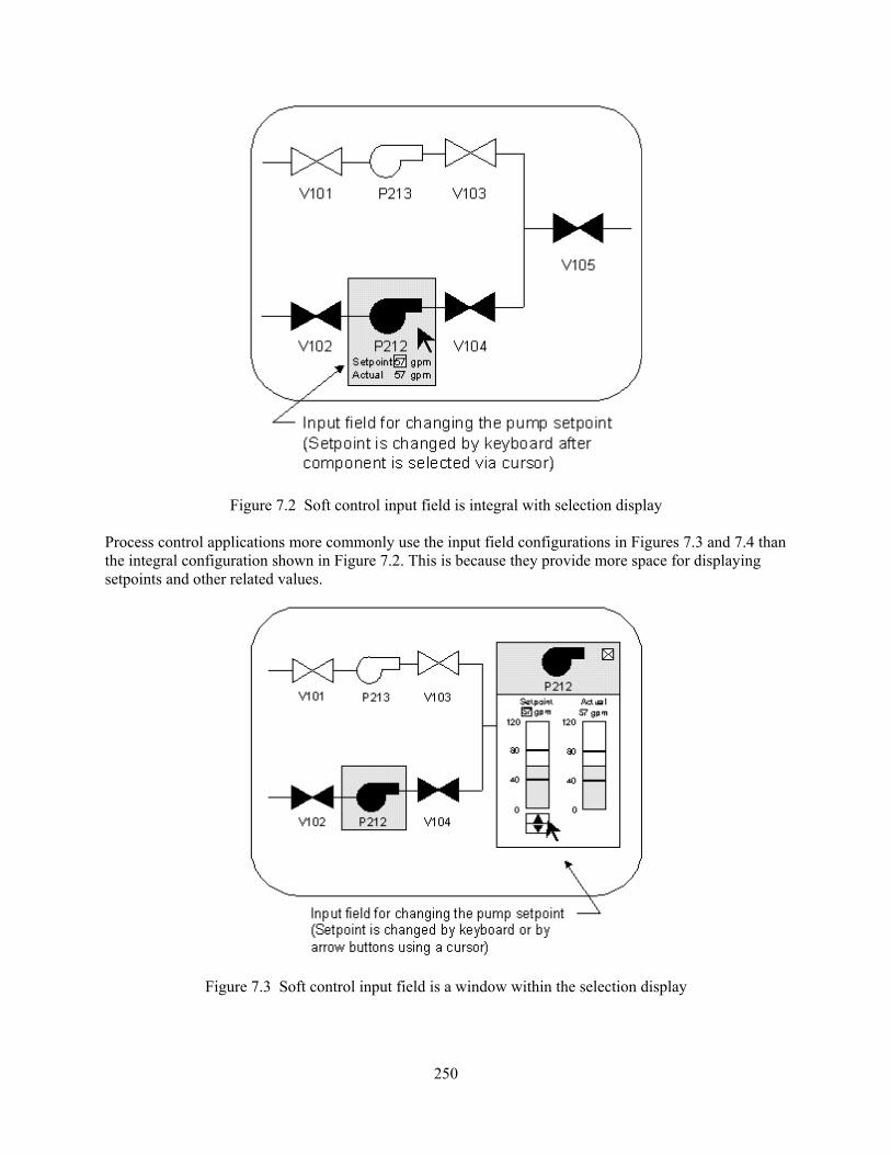
250
Figure 7.2 Soft control input field is integral with selection display Process control applications more commonly use the input field configurations in Figures 7.3 and 7.4 than the integral configuration shown in Figure 7.2. This is because they provide more space for displaying setpoints and other related values.
Figure 7.3 Soft control input field is a window within the selection display

251
Figure 7.4 Soft control input field and selection display are on separate display devices
Once an input field has been accessed, three categories of inputs can affect the state of the plant: command inputs, discrete values, and continuous values. The section below describes each. A command is an instruction to a computer or system requesting it to perform an action. For example, commands may be given to obtain, transfer, process, store, retrieve, delete, or display information about plant status. Commands may also be used to control the plant (e.g., as an instruction to an automatic control system to perform a function, such as shutting down a piece of equipment). A discrete variable has a defined set of individual values. The input action involves selecting one of them. Many control actions involve selecting from a discrete set of states. For example, plant breakers and valves may be changed from the open to the closed state.
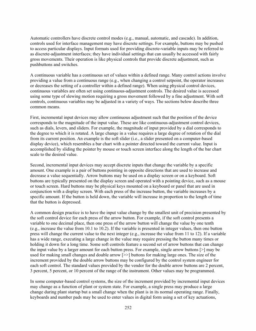
252
Automatic controllers have discrete control modes (e.g., manual, automatic, and cascade). In addition, controls used for interface management may have discrete settings. For example, buttons may be pushed to access particular displays. Input formats used for providing discrete-variable inputs may be referred to as discrete-adjustment interfaces; they have individual settings that can usually be accessed with fairly gross movements. Their operation is like physical controls that provide discrete adjustment, such as pushbuttons and switches. A continuous variable has a continuous set of values within a defined range. Many control actions involve providing a value from a continuous range (e.g., when changing a control setpoint, the operator increases or decreases the setting of a controller within a defined range). When using physical control devices, continuous variables are often set using continuous-adjustment controls. The desired value is accessed using some type of slewing motion requiring a gross movement followed by a fine adjustment. With soft controls, continuous variables may be adjusted in a variety of ways. The sections below describe three common means. First, incremental input devices may allow continuous adjustment such that the position of the device corresponds to the magnitude of the input value. These are like continuous-adjustment control devices, such as dials, levers, and sliders. For example, the magnitude of input provided by a dial corresponds to the degree to which it is rotated. A large change in a value requires a large degree of rotation of the dial from its current position. An example is the soft slider (i.e., a slider presented on a computer-based display device), which resembles a bar chart with a pointer directed toward the current value. Input is accomplished by sliding the pointer by mouse or touch screen interface along the length of the bar chart scale to the desired value. Second, incremental input devices may accept discrete inputs that change the variable by a specific amount. One example is a pair of buttons pointing in opposite directions that are used to increase and decrease a value sequentially. Arrow buttons may be used on a display screen or on a keyboard. Soft buttons are typically presented on the display screen and operated with a pointing device, such as a mouse or touch screen. Hard buttons may be physical keys mounted on a keyboard or panel that are used in conjunction with a display screen. With each press of the increase button, the variable increases by a specific amount. If the button is held down, the variable will increase in proportion to the length of time that the button is depressed. A common design practice is to have the input value change by the smallest unit of precision presented by the soft control device for each press of the arrow button. For example, if the soft control presents a variable to one decimal place, then one press of the arrow button will change the value by one tenth (e.g., increase the value from 10.1 to 10.2). If the variable is presented in integer values, then one button press will change the current value to the next integer (e.g., increase the value from 11 to 12). If a variable has a wide range, executing a large change in the value may require pressing the button many times or holding it down for a long time. Some soft controls feature a second set of arrow buttons that can change the input value by a larger amount for each button press. For example, single arrow buttons [>] may be used for making small changes and double arrow [>>] buttons for making large ones. The size of the increment provided by the double arrow buttons may be configured by the control system engineer for each soft control. The standard values provided by the vendor for the double arrow buttons are 2 percent, 3 percent, 5 percent, or 10 percent of the range of the instrument. Other values may be programmed. In some computer-based control systems, the size of the increment provided by incremental input devices may change as a function of plant or system state. For example, a single press may produce a large change during plant startup but a small change when the plant is in its normal operating range. Finally, keyboards and number pads may be used to enter values in digital form using a set of key actuations,
253
e.g., the value “100.7.” Section 7.3.7 presents review guidelines for control inputs. Handling Stored Data This section addresses the protection of stored data, including minimizing irreversible actions. Section 7.3.8 presents review guidelines for handling stored data. System Response This section addresses the response of the soft control to user input, including providing feedback, alerting users to mode changes, and delaying actuation when practical to provide users with the opportunity to make corrections. Section 7.3.9 presents review guidelines for system response. A comprehensive review of a soft control system design should include how it is affected by degraded HSI and I&C conditions. Degraded conditions can have significant impacts on proper HSI functioning. Section 14 provides guidance for reviewing degraded HSI and I&C conditions. Bibliography Source Code Documents 6546 O’Hara, J. and Brown, W. (2001). Human-System Interface Management: Human Factors
Review Guidance (BNL Tech Report No. W6546-T6A-1-3/01). Upton, NY: Brookhaven National Laboratory.
6635 Stubler, W., O’Hara, J., and Kramer, J. (2000) Soft Controls: Technical Basis and Human
Factors Review Guidance (NUREG/CR-6635). Washington, DC: U.S. Nuclear Regulatory Commission.
7.1 General 7.1-1 Coordinating Soft Control Use among Operators If a soft control can be accessed from more than one location in the HSI, protective measures should ensure its coordinated use among multiple users. Additional Information: The HSI should be designed to allow operators to maintain awareness of each other’s use of the soft control so their actions do not interfere. For example, two operators should not be able to operate the same soft control simultaneously from different places without being aware of each other’s actions. Coordination problems may be minimized by assigning the control capability for a soft control to a particular individual or workstation (e.g., while the settings of a soft control can be viewed from multiple display devices, it can only be operated from one device). Alternatively, coordination may be supported by features that restrict access to soft controls one user at a time and by group-view displays that allow operators to observe each other’s actions.6635 7.1-2 Indication of Shared Control Capability If a control function is shared among users but only one user can operate it at a time, a clear, unambiguous indication should be provided identifying which user has the control capability.6546
254
7.1-3 Indication of Override of Shared Control Capability A clear, unambiguous indication should be provided before overriding the use of a shared control. Additional Information: An override capability allows one user to take the control capability of a shared control from another user. If such an override capability exists, then a clear indication should be provided before each override so that users are aware of the pending change.6546 7.1-4 Soft Controls with Multiple Access The system should make each user aware of control inputs made by others and ensure that the control actions of one user are not unknowingly reversing another user’s actions. Additional Information: Some input interfaces for controlling plant variables can be accessed from multiple locations in the HSI. Some process plants with computer-based HSIs address this problem by assigning control capabilities for a plant variable to a particular control console. Users at other consoles can observe the control setting but cannot initiate changes.6546 7.1-5 Operation with Protective Clothing Soft controls should be designed to accommodate any protective clothing that personnel may be required to wear. Additional Information: In some plant locations, environmental conditions necessitate wearing protective clothing that can limit the ability of personnel to manipulate soft controls. For example, gloves may reduce manual dexterity and tactile sensitivity, degrading the ability of personnel to operate soft controls quickly and accurately. As another example, eye protection, such as goggles, may become foggy or distort vision and, thus, interfere with a person’s ability to view computer-based display devices.6635
7.2 Information Display 7.2.1 General 7.2.1-1 Representing Relationships Between Control System Components The display capabilities of soft controls should allow users to quickly assess the status of individual components of a control system and their relationships with other components. Additional Information: Because of the limited size of the display devices used with soft controls, not all components of a control system may be visible to the operator at once. However, they should allow the operator to rapidly view relationships between functionally related components. For example, if a controller is part of a hierarchical control system, the operator should be able to see higher level controllers that provide control inputs and lower level ones that receive inputs. Rapid assessment of the control system’s status should be supported by such features as displays that depict these relationships and retrieval mechanisms that give rapid access to detailed information on individual control system components.6635 7.2.1-2 Making Options Distinct An interface should be designed so that users can, at a glance, distinguish options by such characteristics as context, visually distinct formats, and separation. Additional Information: Slips involve errors in performing well-practiced, unconscious actions. Description errors, a type of slip, involve performing the wrong set of well-practiced actions for the situation. They occur when the information that activates or triggers the action is either ambiguous or undetected. Many control input actions involve the selection of options, such as choosing between alternative commands or selecting a plant component to perform a control action upon it. Description errors that result in selecting a similar but incorrect option may be prevented by organizing options to supply context (such as by functional organization), making options visually distinct, and separating options that users may confuse. Options may be separated by placing them on different display pages or different display devices.6635

255
7.2.2 Selection Displays 7.2.2-1 Visually Distinct Selection Displays Displays used for selecting components and variables should be visually distinct to support the choice of the correct display. Additional Information: A selection display shows a set of components or variables that may be chosen for a control action. One common format is the mimic, in which components are arranged as a schematic diagram. Excessive reuse of layouts and display elements in mimic displays may cause them to look alike and so may contribute to operators searching the wrong selection display for the component that they wish to manipulate. Selection displays should be laid out and labeled so operators readily recognize and distinguish them.6635 7.2.2-2 Visually Distinct Components The representation of components and variables within selection displays should be visually distinct to support their correct selection. Additional Information: Using a standard set of symbols and layout conventions in displays is important in reducing the mental workload associated with finding and interpreting information. However, these factors may also cause components to look alike and may contribute to operators selecting the wrong component. The symbols and graphic icons used to represent different types of components should be designed to be readily recognized and distinguished. In addition, they should be clearly labeled for correct identification.6635 7.2.2-3 Identification of Loops on Multiple-Loop Controllers The loops of multiple-loop controls should be distinctly marked to prevent the selection or use of the wrong loop. Additional Information: A multiple-loop controller is a digital controller that can control multiple variables through independent channels, one per control loop. Each channel acts as a separate control device. For example, a single controller may be capable of controlling 10 different variables, each on a separate control loop. Operators access these loops through the user interface of the controller device. However, because there may be few cues to identify the loops, operators may fail to correctly recognize the loop accessed and may control the wrong variable.6635
7.2.3 Input Fields 7.2.3-1 Cues for Matching Input Fields to Selection Displays A user looking at the field for providing a control input should be able to determine which plant component or variable is being controlled. Additional Information: The design of a soft control should provide a salient link between the input field and the corresponding variable or component. Starting at the input field, the operator should be able to quickly trace the component or variable back to its representation in the display that was used to select it. Three methods that might be used are graphic coding, landmarks, and animation. Graphic codes, such as borders, symbols, and colors, may be applied to both the representation of the component in the display from which it was selected and to the input field, making a strong visual association between them. For example, if the selection display has a mimic format, the input field may contain the symbol for the selected component. It also may contain symbols for the components that precede and follow it in the flow path. Animation may be used when an input field is opened and closed. The input field could appear to “pop out” of an option selected from a display and “go back” into the option when the field is closed.6635

256
7.2.3-2 Labeling of Input Fields The input field should be labeled with sufficient information to uniquely identify its corresponding component. Additional Information: Labeling should include a unique identification code for the component, matching its representation in the selection display. It may also describe the component (e.g., valve, pump, breaker) and identify those components that immediately precede and follow it in the system.6635 7.2.3-3 Coordination of Soft Controls with Process Displays Displays should be readily accessible from the input field, so the user can easily verify that the control actions have had the intended effect on plant systems and processes. Additional Information: Inadequate coordination of input fields with plant process displays can make it difficult for operators to verify that control actions have had the desired effects on plant systems and processes.6635 7.2.4 Input Formats 7.2.4-1 Appropriate Use of Discrete-Adjustment Interfaces Discrete-adjustment interfaces should be used for selecting among a set of individual settings or values. Additional Information: Discrete-adjustment interfaces are computer-based formats with individual settings that can be accessed by gross movements; their operation is like discrete-adjustment controls, such as pushbuttons. By contrast, continuous-adjustment interfaces are computer-based formats that have continuous ranges usually accessed using some type of slewing motion, requiring a gross movement followed by a fine adjustment; their operation is like that of continuous-adjustment controls, such as rotary dials or sliders. Discrete-adjustment interfaces are preferred when the user must select one option from a limited number of choices, or when precision requirements are such that a limited number of settings can represent the entire continuum of values. The most common discrete-adjustment interfaces used with soft controls are individual buttons and radio buttons (a group of buttons representing a set of related options). However, other formats also are possible, such as rotary selector dials operated by cursor or gestural interfaces. Some computer interfaces have a continuous-adjustment control, such as a slider or scroll bar, for looking at a group of individual options. Because choosing a specific setting with a continuous-adjustment control can be awkward, there should also be a discrete-adjustment control, such as a set of arrow buttons.6635 7.2.4-2 Labeling Selection Options in Discrete-Adjustment Interfaces The selection options in discrete input formats should be clearly labeled.6635 7.2.4-3 Feedback for Discrete-Adjustment Interface with Multiple Settings Discrete-adjustment interfaces should indicate which setting was selected.6635
7.2.4-4 Feedback for Discrete-Adjustment Interface with Continuous Operation If a discrete-adjustment interface has continuous operation, it should provide continuous feedback on the current state. Additional Information: A continuous-operation control continues to produce an effect until the user provides the next input, or until a predefined action sequence is stopped by a termination criterion. An example is a button that changes to the activated state when pressed and remains in that state until it is pressed again. An example of continuous feedback in a soft control is a checkbox format in which an “X” appears in the box to indicate that an option has been selected and disappears only after the option is deselected.6635
7.2.4-5 Appropriate Use of Continuous-Adjustment Interfaces Continuous-adjustment interfaces should be used when precise adjustments along a continuum are needed

257
or when many discrete settings are present. Additional Information: Continuous-adjustment interfaces, such as soft sliders, provide continuous adjustment and are, therefore, suited to selecting a setting from a continuum. Because these interfaces often require a gross slewing movement followed by fine adjustment, setting them correctly may require more time and attention than discrete input formats. Therefore, they should not be used in place of a discrete-adjustment interface for selecting from a small set of options. 6635 7.2.4-6 Appropriate Use of Soft Sliders A soft slider should be considered as an input device when the range of possible values and the ratio of a value to that range need to be displayed. Additional Information: A soft slider (also called a slider bar or a scroll bar) is an input format used to directly manipulate a variable over a set range of values. Soft sliders are typically maneuvered by pointing interfaces, such as a touch screen or mouse. They may require careful hand-eye coordination to ensure that the pointing device does not leave the linear path of the slider nor overshoot or undershoot the intended target. If the user’s tasks do not permit careful hand-eye coordination, then other interfaces, such as arrow keys, should be used. The slider sometimes is combined with arrow buttons.6635 7.2.4-7 Indicating the Range of Values on Soft Sliders The range of values should be indicated on horizontal sliders with the low value on the left and the high value on the right and on vertical sliders with the low value on the bottom and the high value on the top.6635 7.2.4-8 Displaying the Digital Value on Soft Sliders The numeric value to which a soft slider is set should be presented in digits on the soft slider.6635 7.2.4-9 Dimensions of Soft Sliders The physical dimensions of the soft slider should allow the user to read the current and target positions and position the slider with the required precision, accuracy, and response time. Additional Information: The length of the slider is determined, in part, by the range of values depicted, the increments between individual values, the degree of precision required for reading the slider’s position, and the user’s expected viewing distance. The accuracy with which the slider may be positioned may be affected by characteristics of the input device (e.g., mouse devices may allow more accurate positioning than a touch interface because of the size and irregular shape of the finger). A very short slider may be difficult to read or position precisely. A very long slider may produce slow response times because of the long distance that must be traveled and the need to keep the pointing device on its linear path.6635 7.2.4-10 Depicting Critical Ranges on Soft Sliders When part of the range of values depicted by a soft slider represents critical information, such as alarm limits, those values should be coded to facilitate recognition. Additional Information: Graphic codes may be applied to distinguish the normal operating range, alarm limits, and other abnormal operating ranges.6635 7.2.4-11 Appropriate Use of Arrow Buttons A set of arrow buttons should be considered as the input device when it is desirable to incrementally increase or decrease a variable from its previous value. Additional Information: Arrow buttons change values sequentially as each increase or decrease button is pressed. In addition, values may change continuously if a button is held down. These inputs provide feedback about the magnitude of the change (i.e., the magnitude increases with the number of presses or the time that a button is held down). Such feedback may reduce the likelihood of producing large errors or increase the likelihood of detecting them. Some soft controls have two sets of arrow buttons, one for

258
small and one for large incremental changes. Arrow buttons are sometimes combined with a slider in a soft control.6635 7.2.4-12 Indicating Current Value for Arrow Buttons Arrow buttons should have a display indicating the current value of the variable being controlled. Additional Information: The current value should be shown in a format consistent with the type of variable being controlled. Numeric values should be presented as digits, and textual values (e.g., Low, Medium, and High) as words.6635 7.2.4-13 Uniform Changes in Values by Arrow Buttons Each press of an arrow button should change the current value uniformly.6635 7.2.4-14 Feedback Regarding Arrow Button Actuation Arrow buttons should provide salient feedback when they are actuated. Additional Information: Feedback should be sustained when the button is held down and momentary when the button is momentarily pressed.6635 7.2.4-15 Apparent Operation of Arrow Buttons Labeling and other coding should be used when the operation of the arrow buttons is not apparent. Additional Information: For example, when arrow buttons are used to change a date display, it may be unclear whether actuating a button will incrementally change the days (and change the month when the last day is reached), or whether the month and day values are changed separately after being selected by the user. The arrow buttons should be labeled or coded to indicate their effects.6635
7.2.4-16 Reference Values for Continuous Variable Inputs Reference values should be provided to help the user judge the appropriateness of values when entering continuous variable inputs. Additional Information: Reference values commonly used in process control applications include the variable’s range, alarm limits, and current value. Reference values may be presented as digits or graphs.6635 7.2.5 Display Devices 7.2.5-1 Adequate Display Area Adequate display space should be provided so that short-term monitoring and control tasks do not interfere with longer term tasks. Additional Information: Making control actions available through a general-purpose display device may require other plant information to be removed from the user’s view. Sufficient general-purpose display devices should be provided so that short-term control actions can be undertaken without interfering with long-term ones (e.g., they can be performed on separate devices). Alternatively, control actions can be supported by dedicated special devices.6635 7.3 User-System Interaction 7.3.1 General 7.3.1-1 Minimizing Soft Control Modes The excessive use of modes in soft controls should be avoided. Additional Information: Modes occur in soft controls when a display or input device is designed for more than one function. For example, a soft control that is used for manipulating multiple variables may have a separate mode for each one (e.g., individual modes for variables A, B, and C). In addition, there may be
259
multiple modes for a single variable, each allowing it to be controlled in a different way (e.g., variable A may have separate modes for manual control, automatic control, and testing). Mode errors occur when the user believes the device is in one mode when it is in another and, as a result, performs an inappropriate input action. The likelihood of mode errors can be lessened by reducing the number of modes; if multiple modes do not exist, then mode errors cannot occur.6635 7.3.1-2 Distinctive Indication of Soft Control Modes When multiple modes exist, they should be distinctively marked so the user can determine the current mode at a glance. Additional Information: Distinct labels may be used to indicate the currently active mode.6635 7.3.1-3 Coordination of Destructive and Safety-Significant Commands across Modes A command that produces a benign action in one mode should not cause a different action with serious negative consequences in another mode. Additional Information: A command is an instruction provided by a user asking a computer system to perform a particular action. Actions that are destructive (e.g., delete file) or have serious safety consequences should have unique commands. For example, the function key “F2” should not have a benign action, such as listing a directory, in one mode but a destructive action, such as deleting a file or operating important plant equipment, in another mode.6635 7.3.1-4 Unique Commands for Destructive and Safety-Significant Commands Unique commands associated with actions that have important consequences should not be easily confused with other commands used in the same or different modes. Additional Information: Reserving special commands for special actions can prevent mode errors because, if the command is entered while the device is in the wrong mode, it will not be accepted by the system. A unique or reserved command should not be so similar to other commands that a valid entry may result from incorrectly entering another command. For example, if the command “CNTL X” is reserved for a special action, then similar commands, such as “ALT X” and “Shift X,” should not be valid, even in other modes. The combination of a mode error and the incorrect entry of the command may execute an unintended action.6635 7.3.1-5 Discrimination of Interface Management Actions and Process Control Actions The design of the user interface should clearly distinguish between interface management actions and process control actions. Additional Information: Actions required for interface management tasks and plant control tasks should look different. This may be accomplished by providing different interfaces, different coding for interfaces, and, possibly, different input devices.6635 7.3.1-6 Reducing the Likelihood of Unintended Actuation For actions that can have significant negative consequences, the user interface should be designed to reduce the likelihood of unintended actuation by requiring deliberate action for their execution. Additional Information: Deliberate actions should be required for inputs having serious potential consequences. Actions that require physical effort in the form of multiple steps or higher actuation forces may be less likely to occur accidentally as the result of a random motion of the user. In addition, actions that require greater attention, such as multiple steps and checks, may reduce the likelihood that the user will revert to the type of “automatic” activity that could cause a slip. However, control actions that require multiple steps also should be designed to reduce the likelihood of other errors (i.e., the failure to complete a set of steps in the correct order).6635

260
7.3.1-7 Feedback for Selected Actions before Execution The HSI should give the user feedback indicating the action that was selected and allowing the action to be canceled before it is executed. Additional Information: The goal of this recommendation is to avoid unintended manipulation of plant equipment or unintended interface management actions. Feedback about the selected option is important because a broad range of actions may be accessed through a soft control device, including manipulation of various plant components and of the user interface. The close proximity and similarity of input options within the display area may result in users selecting the wrong ones. Users should be able to cancel or modify an action if they determine that its execution would be undesirable.6635 7.3.1-8 Use of Error-Mitigation Approaches Error-mitigation approaches should not be the sole means for achieving error tolerance but should be used in conjunction with other means for error prevention and system-assisted error detection. Additional Information: Error-mitigation mechanisms limit the effects of incorrect inputs after they have been entered into the control system. Two strategies include reducing the rate of the system’s response and deferring it. Both are intended to provide time for detecting and correcting input errors and for reversing them. Error mitigation should not be considered a substitute for error prevention and detection.6635 7.3.1-9 Undo Features If undo features are provided, they should be consistently available. Additional Information: Undo features minimize the effects of users’ errors by allowing them to undo or reverse previous actions. Users tend to rely upon undo features and incorporate them into their work. Failures of undo features may have worse consequences than if they were not provided in the first place. For example, operators may be more willing to delete files if they think they can recover them.6635 7.3.2 Sequential Actions 7.3.2-1 Indicating the Status of Sequential Actions Computer-based HSIs should support users in rapidly assessing the status of sequential actions in progress. Additional Information: An action sequence is a set of operations that must be performed in a specific order. Errors involving misordering the components of an action sequence include skipped, reversed, and repeated steps. Soft controls may be more prone to this type of slip than conventional controls because they introduce additional operations for accessing controls and displays and provide inputs that also often have sequential constraints on their execution. In addition, many control operations must be performed in particular sequences. For example, when configuring a fluid system, it may be necessary to establish the flow path, control mode, and setpoint of a flow controller in a specific sequence of operations (e.g., A, B, C, D, and E). One form of error occurs when a user skips a step, thinking that it was completed. For example, a user may perform operations A, B, and C and after some delay or interruption, may perform operation E thinking that D was finished. The repetitiveness of the task is a factor in this type of error. If a user has performed a set of operations repeatedly on several identical controllers, the memory of performing a particular operation on the other controllers may increase the likelihood of the user incorrectly concluding that the operation was completed on the present controller. Thus, the sequentiality of soft controls can interact with repetitive, sequential tasks to increase the probability of errors involving misordering the components of the action sequence. The display design of computer-based HSIs should support users in identifying tasks that are in progress; ideally, they should be designed so that the status of related operations (e.g., A, B, C, D, and E) can be checked at a glance from a single display.6635
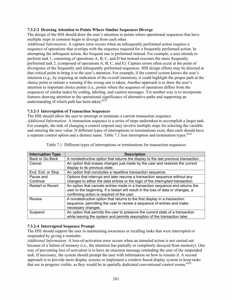
261
7.3.2-2 Drawing Attention to Points Where Similar Sequences Diverge The design of the HSI should draw the user’s attention to points where operational sequences that have multiple steps in common begin to diverge from each other. Additional Information: A capture error occurs when an infrequently performed action requires a sequence of operations that overlaps with the sequence required for a frequently performed action. In attempting the infrequent action, the frequent one is performed instead. For example, a user intends to perform task 1, consisting of operations A, B, C, and D but instead executes the more frequently performed task 2, (composed of operations A, B, C, and E). Capture errors often occur at the point of divergence of the frequently and infrequently performed sequences. HSI design efforts may be directed at that critical point to bring it to the user’s attention. For example, if the control system knows the user’s intention (e.g., by requiring an indication of the overall intention), it could highlight the proper path at the choice point or initiate a warning if the wrong one is taken. Another approach is to draw the user’s attention to important choice points (i.e., points where the sequence of operations differs from the sequences of similar tasks) by coding, labeling, and caution messages. Yet another way is to incorporate features drawing attention to the operational significance of alternative paths and supporting an understanding of which path has been taken.6635 7.3.2-3 Interruption of Transaction Sequences The HSI should allow the user to interrupt or terminate a current transaction sequence. Additional Information: A transaction sequence is a series of steps undertaken to accomplish a larger task. For example, the task of changing a control setpoint may involve multiple steps for selecting the variable and entering the new value. If different types of interruptions or terminations exist, then each should have a separate control option and a distinct name. Table 7.1 lists interruption and termination types.6635
Table 7.1 Different types of interruptions or terminations for transaction sequences
Interruption Type Description Back or Go Back A nondestructive option that returns the display to the last previous transaction. Cancel An option that erases changes just made by the user and restores the current
display to its previous state. End, Exit, or Stop An option that concludes a repetitive transaction sequence. Pause and Continue
Options that interrupt and later resume a transaction sequence without any changes to either the data entries or the logic of the interrupted transaction.
Restart or Revert An option that cancels entries made in a transaction sequence and returns the user to the beginning. If a restart will result in the loss of data or changes, a confirming action is required of the user.
Review A nondestructive option that returns to the first display in a transaction sequence, permitting the user to review a sequence of entries and make necessary changes.
Suspend An option that permits the user to preserve the current state of a transaction while leaving the system and permits resumption of the transaction later.
7.3.2-4 Interrupted Sequence Prompt The HSI should support the user in maintaining awareness or recalling tasks that were interrupted or suspended by giving a reminder. Additional Information: A loss-of-activation error occurs when an intended action is not carried out because of a failure of memory (i.e., the intention has partially or completely decayed from memory). One way of preventing loss of activation is to have an onscreen message reminding the user of the suspended task. If necessary, the system should prompt the user with information on how to resume it. A second approach is to provide more display screens or implement a window-based display system to keep tasks that are in progress visible, as they would be in spatially dedicated conventional control rooms.6635

262
7.3.2-5 Resumption of Interrupted Sequences A minimum number of actions should be required to resume a control-action sequence that was temporarily suspended. Additional Information: When a user has interrupted a sequence of operations, a minimum number of actions should be required to resume it. The user should not be required to restart the sequence from the beginning. One way of supporting the user in finding a display containing a suspended task is to have a “previous display” feature that accesses a sequence of previous displays. A second approach is an interaction history feature that lists previously accessed displays and provides access to them. A third method is to include a “bookmark” feature allowing users to designate displays containing tasks that are in progress. Thereafter, few actions or none should be required to resume the task.6635 7.3.3 Verification and Confirmation Steps 7.3.3-1 Separate Action for Verification Steps Verification steps should be separate from input actions. Additional Information: Verification steps are usually steps added to the input action. For example, the user selects an option and then presses the Enter key to verify it. Verification steps reduce the likelihood of input errors by increasing the effort (i.e., the number of steps) and drawing users’ attention to the input operation. However, they can lose their effectiveness if users can perform them unconsciously as part of the input action.6635 7.3.3-2 Confirmation of Goals When feasible, confirmation steps should draw attention to the goal of the action, not just to the action. Additional Information: Confirmation steps require the user to respond to a warning or advisory message. For example, the user may respond to the question, “Are you sure you want to do this?” by pressing “Yes” or “No.” Like verification steps, confirmation steps attempt to reduce input errors by increasing the effort (i.e., the number of steps) and drawing users’ attention to the input operation. A problem with confirmation steps is that they are often ill timed, occurring just after the user initiated the action and is still fully content with the choice. If the user requests an action but specifies the wrong object to be acted upon (e.g., the user requests a file deletion but specifies the wrong file), the system’s request for confirmation is not likely to help the user detect the error. At this point, the user is apt to focus on confirming the action (e.g., deletion) rather than the object (e.g., which file). The potential benefits of confirmation steps should be weighed by comparing their effects on the user’s response time (e.g., potential delays) to the potential consequences associated with the errors that are being guarded against.6635 7.3.4 Interlocks, Lockouts, and Lockins 7.3.4-1 Use of Interlocks, Lockouts, and Lockins Interlocks, lockouts, and lockins should be provided to restrict personnel actions that may affect plant safety. Additional Information: An interlock is a feature that requires user actions to proceed in a specific sequence. A lockout prevents personnel from providing input that may generate a negative effect. Statically defined lockouts may restrict inputs to a specific, predefined range or set of values. Context-sensitive lockouts may restrict input values based on the current situation. A lockin keeps an ongoing operation active by preventing personnel from terminating it prematurely. Personnel actions that may affect plant safety include control actions and manipulating stored data important to safe plant operation.6635 7.3.4-2 Override of Interlocks, Lockouts, and Lockins The design of interlocks, lockouts, and lockins should not limit the users’ authority unless there is a clear

263
safety reason. Additional Information: Error-prevention measures (e.g., interlocks, lockouts, and lockins) that cannot be overridden by the user may be detrimental to safety. Sometimes a normally undesirable tactic may be the only thing a user can do to solve a problem.6635 7.3.4-3 Visibility of Interlocks, Lockouts, and Lockins Interlocks, lockouts, and lockins should be designed to indicate which actions are being blocked and what conditions activated the block. Additional Information: A lockout blocks inputs that it considers unacceptable or not achievable. When this occurs, the user should be able to determine why an input was blocked and what inputs are acceptable, especially for context-sensitive validation in which complicated rules may be used for assessing the acceptability of an input value. An interlock should inform the user of the condition(s) that activated it and the conditions that must be satisfied to release it. Lockin features should show the user what action is being “locked in” (i.e., the action that is being caused to operate without interruptions) and how it can be canceled.6635 7.3.4-4 Automatic Logging of the Activation of Interlocks, Lockouts, and Lockins The activation of an interlock, lockout, or lockin should be automatically logged.6635 7.3.4-5 No Automatic Actuation of Blocked Actions An interlock, lockout, or lockin should not initiate an action that was previously blocked merely because the status of the triggering condition has changed. Additional Information: If operation B was blocked because condition A was not satisfied, the system should not automatically start operation B when condition A is met. Instead, a separate action should be required (e.g., the user should be required to take a specific action to allow operation B to resume).6635 7.3.5 Error Detection and Correction 7.3.5-1 Warning Message Content Warning messages should draw users’ attention to the goal of the action, not just to the action. Additional Information: Actions may be described in many levels of detail. Often, error messages are not effective because they are directed toward the wrong level of detail, so that the description of what is wrong may not match the user’s understanding of what was done. An alternative is to allow the user to interrogate the warning. For example, the initial warning could be given at a very high level, corresponding to the system’s understanding of the user’s intent but then could allow the user to obtain information at lower, more detailed levels, such as describing how the action was performed and why it was inappropriate for the goal.6635 7.3.5-2 Automatic, Self-Correct Features for Interface Management Action Automatic, self-correcting features should only be used for interface management actions, such as retrieving displays. Additional Information: Automatic, self-correcting features detect and automatically correct errors that users make when providing inputs; for example, a “Delete” command that is incorrectly entered as “DLE” will be automatically changed to its correct form “DEL” and then executed. These systems can interfere with a user’s activities if their error-detection facilities are overgeneralized (i.e., they interpret correct entries as being errors), since the system may substitute an incorrect response for the correct one provided by the user, thereby affecting plant operation and safety. Additional mental burdens may be imposed on the user to learn, remember, and anticipate the types of correct inputs that these systems will interpret as errors. Therefore, automated, self-correcting features should not be employed for plant-control actions. Instead, other approaches should be used, such as warnings and confirmation steps.6635

264
7.3.5-3 Undo Capabilities for Self-Correct Features Automatic, self-correcting features should only be used if they include good “Undo” capabilities, so that the user can reverse inappropriate changes made by the system.6635 7.3.5-4 Use of Inspection and Transfer Steps Inspection and transfer steps should be considered if inputs are complex, or if incorrect inputs can seriously affect safety. Additional Information: Inspection and transfer steps are intermediate steps included in a sequence of operations to create additional opportunities for detecting and correcting faulty inputs. Rather than entering data directly into the control system, the data may be sent to a holding file for review and approval. Thereafter, a command may be entered to transfer the data from the holding file into the active portion of the control system.6635 7.3.6 Selecting Plant Variables or Components 7.3.6-1 Identification of Plant Variables and Components The HSI should support the users’ identification of plant variables and components based on recognition rather than relying strictly upon recall. Additional Information: The HSI should present the options available to users for selecting plant variables and components. For example, they may be shown on menus or mimic displays to facilitate recognition. Where there are multiple variables, their selection should not be based strictly upon the ability of operators to recall components’ identification codes.6635 7.3.6-2 Simple Input Actions for Selection The user should be able to select a component or variable from a display by using simple input actions. Additional Information: Multiple steps or complex input operations, such as transcribing identification codes, should be avoided. The demands of selecting should be minimized so as not to compete with cognitive resources needed for assessing plant conditions and planning responses. However, in some cases, such as for controls that are very important to plant safety, more complex actions may be required to reduce the likelihood of accidental actuation.6635 7.3.6-3 Minimize Action-Sequence Errors for Selecting Plant Variables If a sequence of actions is required to select a component or variable, the HSI should be designed to prevent misordered action-sequence errors. Additional Information: When a soft control is used to manipulate multiple plant components or variables, the user may need to select one, perform the control action, and then deselect it before controlling the next. Errors involving misordering the components of an action sequence may occur. If the user fails to deselect the last component or variable (i.e., the one that was previously controlled), the control action may be performed on the wrong one. The HSI may minimize the likelihood of misordered action-sequence errors by minimizing the number of selection steps, reducing sequential constraints on selection steps, and providing feedback for identifying out-of-sequence steps.6635 7.3.6-4 Minimize the Number of Retrieval Steps for Controls that Are Used Together When a group of controls must be used together, their retrieval should require a minimal number of actions. Additional Information: Excessive selection steps can prevent prompt access to controls and can cause misordered action-sequence errors. One approach to reducing the number of selection actions is to present, on the same display, controls that are used together.6635

265
7.3.7 Control Inputs 7.3.7-1 No Activation When Display Is Inoperable Users should not be able to activate a soft control if its display is not working. Additional Information: A reported problem with touch screens is that sometimes their buttons may remain active even though the video image is not visible. Thus, a user could touch a blank screen and provide a valid input. Such problems may be avoided by requiring multiple actions, such as separate selection and activation steps, for inputs that may have serious consequences (e.g., affect the operation of plant equipment).6635 7.3.7-2 Automatic Reset of Multiple Variable Controls If an input device controls more than one variable, the user should not have to reset the device to match the value of the new variable before executing a control action. Additional Information: When switching between variables, the control should automatically display the current value of that variable and position the input device consistent with that value. The user should not have to adjust the input device to match the current value of a new variable. For example, if variable A is currently set at a value of 100 and variable B at 10, when selecting the latter, the user should not have to adjust the input device to the 10 position before executing a control action.6635 7.3.7-3 Numeric Input Values The HSI should provide feedback to support the user in verifying the correctness of numeric values entered. Additional Information: At a minimum, the value should be depicted as a digital readout. However, additional feedback can further aid users in detecting input errors. For example, for control setpoints, reference values can convey the implications of the new value for plant operations and, thus, support the user in identifying a value that is too large or too small. Reference values include the actual value of the process variable, the current setpoint value, the normal operating limits, and the alarm limits. Graphic feedback might include a bar chart depicting the input value (i.e., the bar’s length corresponds to the magnitude of the entered value). The reference values and the graphic representation may be combined.6635 7.3.8 Handling Stored Data 7.3.8-1 Minimize the Use of Irreversible Actions The design of the HSI should minimize the use of irreversible actions for handling stored data. Additional Information: The design of HSI should seek to eliminate irreversible actions in handling stored data. The user should be able to reverse an action with an “Undo” capability. If an action cannot be designed to be reversible, the user interface should be designed to reduce the likelihood of unintended actuation.6635 7.3.8-2 Deferring Execution of Operations that Are Destructive to Stored Information Whenever practical, irreversible operations that destroy stored information should be deferred and require a separate action for their execution rather than being carried out immediately. Additional Information: Operations that are destructive to stored information include modification and deletion of files. One way of making actions reversible is to defer their execution, giving the user an opportunity to reconsider and reverse the action. An example is the command to delete a file. Many computers place the files in a storage location where, depending upon the computer, it may be deleted automatically in the future or remain indefinitely until the user issues a separate command. This feature allows the user to easily recover the file. Such reversible delete features may be beneficial in nuclear power plants for recovering trend information or other data important for the safe operation of the plant.6635

266
7.3.9 System Response 7.3.9-1 Actuation Feedback Soft controls should provide feedback about their operating state after activation. Additional Information: Momentary controls, which operate only during actuation (e.g., while a button is pressed) should provide feedback during operation. Continuous-operation controls, which remain operating after actuation, should provide continuous feedback.6635 7.3.9-2 Notification of Automatic Mode Changes Systems that can change mode automatically should provide feedback to make the user aware of the current mode. Additional Information: The HSI should inform the user of the current operating mode, mode-transition points, limits on actions, and circumstances in which users must assume control. This feedback should help the user assume control without unnecessary actions and without unnecessarily disrupting plant systems and processes.6635 7.3.9-3 Delaying System Response Where appropriate, systems that are sensitive to incorrect inputs should be designed to limit the rate at which these inputs can affect the process. Additional Information: Limiting the rate at which a system responds to a user’s inputs can provide opportunities for the user to detect and correct erroneous material. Methods for delaying system response include programmed limits in the control software, such as maximum ramp rates, and physical limits in plant equipment, such as orifices and dampers, to limit the rate at which processes can respond to inputs. These methods may be used when the system’s slower response will not degrade plant operation or safety. These methods should be used with other methods that prevent errors and detect them.6635
267
8 COMPUTER-BASED PROCEDURE SYSTEM
Computer-Based Procedure System Characterization Procedures are typically written documents (including both text and graphic formats) that present a series of decision and action steps to be performed by plant personnel (e.g., operators and technicians) to accomplish a goal safely and efficiently. Nuclear power plants use procedures for a wide variety of tasks, from administration to testing and plant operation. Computer-based procedure (CBP) systems were developed to assist personnel by computerizing paper-based procedures (PBPs). Their purpose is to guide operators’ actions in performing their tasks to increase the likelihood that the goals of the tasks would be safely achieved. CBPs define decisions to be made and actions to be taken where the goals are unambiguous and the correct or desired course of action is generally known. While the primary focus of the characterization presented below is focused on emergency operating procedures (EOPs), it is recognized that normal and abnormal operating procedures have been important contributors to many serious events and play a significant role in plant safety. Thus, the guidelines in this section may also apply to procedures used in testing, surveillance, troubleshooting, and maintenance, when they are delivered by CBP systems. The design review of CBP systems requires two types of guidance: procedure guidance and human-system interface (HSI) guidance. The first type addresses the human factors aspects of procedure design and is intended to verify that procedures are technically correct and usable. There is considerable guidance on procedure design (e.g., NUREG-0899, “Guidelines for the Preparation of Emergency Operating Procedures,” issued August 1982). In addition, NUREG-0711, “Human Factors Engineering Program Review Model,” Rev. 1 (Element 8, “Procedures”) and NUREG-0800, “Standard Review Plan for the Review of Safety Analysis Reports for Nuclear Power Plants” (Chapter 18), address human factors engineering (HFE) considerations related to the development of procedures. The second type, HSI guidance, covers their design characteristics. CBPs use other HSI resources (e.g., information presented on video display units (VDUs)), and operators interact with the CBP information using the computer system’s dialogue and navigation capabilities. The human factors guidelines in the general sections of this document address many of the characteristics of CBP design. The guidelines in this section emphasize HSI characteristics specific to implementing procedures in computerized form, such as features that help users manage concurrent procedures or monitor continuously applicable steps in an ongoing operation. This section does not address two aspects of CBP system design and implementation. First, the CBP guidance does not address software aspects of CBPs. For a discussion of general software development, testing, and management see NRC Regulatory Guides 1.168 through 1.173 (NRC, 1977 a-f). Second, it does not address procedure maintenance and configuration control. While procedure maintenance and configuration control are equally important for CBPs and PBPs, these two procedure systems are likely to use different mechanisms. The following are aspects concerning CBPs: how procedures are entered into the computer system; how their quality is verified (e.g., no typos or omissions); how errors are identified, tracked and corrected; how changes are incorporated; and how configuration control (i.e., control over revisions and modifications) is provided. NUREG-0899; NUREG-0711, Rev. 1; and NUREG-0800 contain general guidance for procedure maintenance and configuration control developed for PBPs. The following characterization identifies CBP design features and functions important to personnel performance that can be used to describe a CBP system during an HFE design review.
268
Information Display The display elements for CBP systems include the following: procedure identification information; procedure steps; warnings, cautions, notes, and supplementary information; lists; procedure organization; and format and screen layout. The sections below briefly describe them. Procedure Identification Information Procedures are identifiable to the operators and maintenance personnel through the title, procedure number, revision number, and date. Procedures also contain statements of the high-level objective and its applicability, including the procedure category (e.g., emergency or abnormal). Section 8.1.1 provides review guidelines for procedure identification. Basic Steps Steps are the basic unit of the procedure. Each step is composed of a verb and a direct object. In general, the rules of English grammar are followed, and the syntax reflects concise language that is simply stated, explicit, and consistent. Decision steps provide instructions to evaluate conditions and then to choose appropriate action(s) from a predefined set. The decisions may involve conditional logic (i.e., where actions are to be performed only if a specified set of conditions exists). Action steps identify actions to be taken (i.e., instructions to perform physical (e.g., “Depress”) and mental (e.g., “Verify”) actions, as well as describing the objective of those actions. Some procedure steps (e.g., in EOPs) have a dual nature, with an action to be accomplished in one column and a second action if the first is not successful. Some procedure steps may also require calculations. Implementation of procedures has a temporal flow (i.e., some steps are taken when encountered), others are performed continuously (i.e., steps of continuous applicability), while others are based on time or process criteria. Performance of a procedure step may be supported by information, such as cautions and notes, that qualifies the actions and decisions required. Section 8.1.2 provides review guidelines for procedure steps. Warnings, Cautions, Notes, and Reference Materials Warnings alert operators to potential hazards of their actions that may result in death or injury to workers or the public. Cautions alert operators to potential hazards of their actions that may damage machinery or equipment. Notes call attention to important supplementary information that may enhance an operator’s understanding and performance of the procedure. Procedure steps may reference supplementary material that helps the operator implement the step; it can be in the form of tables, figures, lists, text, or numeric information. Section 8.1.3 provides guidelines for reviewing warnings, cautions, notes, and supplementary information. Lists As noted in Section 1, “Information Display,” a list is a display containing alphanumeric strings arranged in a single column by rows. Procedures frequently use lists to present groups of items such as actions, conditions, components, criteria, and systems. When CBPs use lists, additional consideration must be given to the grouping of items, provisioning checkoff capability, and alerting operators of items that may be overlooked. Section 8.1.4 provides review guidelines for these aspects of CBP lists, while Section 1.2.2 presents general review guidelines for list formats.
269
Organization of Procedures Nuclear plant procedures are not like simple checklists in which a user starts at the top and linearly proceeds step by step to the end. Based on plant conditions, the operator may have to branch from one part of a procedure to another or from one procedure to another. Thus, the organization of procedures is an important consideration. Section 8.1.5 provides review guidelines for procedure organization. Formatting and Screen Layout PBPs generally present the basic steps in text or flowchart format. CBPs may use both formats. However, unlike PBPs, CBPs are viewed through the limited display area of one or more VDUs. Thus, whether the procedure format is text or flowchart, the designer must still decide whether the procedure will be presented to the operator in a continuous, scrollable display or divided into discrete display pages. The overall screen layout for presentation of the procedure elements refers to the determination as to what information should be continuously presented and the way individual procedure elements are presented. For example, the procedure title and identification information may be continuously presented at the top of the CBP screen, while the steps are shown on a scrollable window. Cautions may be represented in a separate window. The CBP may also display such supporting features as bookmarks, checklists, and operator comments. Coding capabilities of computer-based displays (e.g., color, flashing, animation, and auditory cueing) can enhance presentation formats, such as text and flowcharts. Coding is generally used to increase the salience of important information. CBPs use coding for conditions such as the following: • whether procedure step logic is satisfied • whether information is static or dynamic with plant state • when a caution is in effect • when a change in the status of a continuously monitored step has occurred CBPs can be designed to allow operators to choose the level of detail in which procedures are presented. For example, operators may select to have less detail displayed when a procedure step is satisfied. Alternatively, an operator may choose to show all the individual evaluations that led to the conclusion that the step is satisfied. Section 8.1.6 provides guidelines for reviewing procedure formatting and screen layout. Functional Capabilities A significant difference between PBPs and CBPs is in the type of functions CBP systems offer for viewing and using the procedures. Procedure functions can be organized into four cognitive categories: monitoring and detection, situation assessment, response planning, and response implementation. In terms of monitoring and detection, operators must monitor process parameters referenced by procedures. Operators must also monitor their own procedure-related actions. The degree of situation assessment needed in using procedures is high. While EOPs enable operators to act without diagnosing the disturbance, operators must assess whether EOP entry conditions exist. Within the procedure, operators assess each decision step by comparing actual values to the procedure’s reference values, evaluating whether cautions are applicable, assessing whether each step is complete, and tracking and remembering their path through the procedure (the procedure history), steps of continuous

270
applicability, and steps that are time or parameter-value dependent. This can be difficult because steps must be evaluated while others are being performed. Operators must also assess the applicability of individual steps because PBPs are generic and not context sensitive (context sensitivity is the selection of procedural information based on plant state). Finally, operators must evaluate the success of the current procedure in achieving the high-level procedure goals and the procedure’s termination conditions. Procedures were originally designed to support response planning. In the case of EOPs, for example, the procedures were intended to assist operators in responding to events by setting out the steps necessary to achieve safety goals. It relieved the operator of the burden of formulating response plans in real time. Instead, the actions necessary to restore and maintain critical safety functions were analyzed in advance by the procedure developer and supplied as a set of detailed instructions. However, operators must still evaluate whether transitions to other parts of the procedure or other procedures are warranted. At rare times, they may have to modify a procedure when the current plant conditions render the existing procedure inapplicable. With respect to response implementation, the operator’s responses involve actions on the procedures themselves, such as making the transition from one step to the next, to other parts of the procedure, or to other procedures. Responses also include controlling equipment based on procedural guidance. CBPs may support operators’ interaction both with the procedures and with plant equipment. While PBPs support response planning, they provide little active support for monitoring, situation assessment, and response. CBPs, on the other hand, may support these cognitive functions as well; the CBP design determines the extent to which they do so. Table 8.1 provides an overall scheme in which the level of automation of CBPs can be organized. This table illustrates the widely varying levels of automation and functional capabilities that CBPs may possess. It also can be used to catalogue the functional capabilities of a particular system.

271
Table 8.1 Levels of automation of procedure functions
Procedure Functions Level of Automation1
Manual Advisory Shared Automated Monitoring and Detection Process parameter values NA Operator actions NA Situation Assessment Procedure entry conditions NA Resolution of procedure step logic NA Step status (incomplete or completed) NA Procedure history NA Context-sensitive step presentation NA Assessment of continuous, time, and parameter steps NA Assessment of cautions NA High-level goal attainment and procedure exit conditions NA Response Planning Selection of next step or procedure Procedure modification based on current situation Response Implementation Transition from one step to the next Transition to other procedures Control of plant equipment
1 NA means “not applicable.” For a given CBP system, a level of automation may not be applicable or an entire function may not be applicable.
In the rows, the general cognitive functions (as described above) are identified along with the procedure-related activities associated with each. In the columns, four levels of automation are identified: manual, advisory, shared, and automated. The meanings of these levels of automation are as follows: • Manual—The operators perform the function with no assistance from the CBP.
• Advisory—The CBP gives advice only. For example, the CBP may advise the operator that
Pump A should be started but does not perform the action.
• Shared—The CBP and the operators both perform the function. For example, a CBP system could monitor a process but be unable to access all necessary information about the system (e.g., valve position) caused by lack of instrumentation. When this type of information needs to be monitored, the operator obtains the information.
• Automated—The CBP performs the function automatically without direct intervention from the
operator. This may or may not involve notification to the operators of the automated actions taken.
A given level of automation is not necessarily meaningful for all functions. For example, with respect to process monitoring, it is not meaningful to have an advisory level of automation. The CBP system will either have monitoring capability or it will not. This is indicated by NA (not applicable) in the table. A given procedure system may make no provisions for a given function. For example, a CBP may not address control of equipment in any capacity, not even manual. In such a system, equipment would be operated using the other HSI resources. Thus, the entire function is not applicable for that specific CBP.

272
Individual CBP systems differ in terms of the levels of automation they provide. To achieve these varying levels of automation, CBPs may need to provide features that go beyond those identified above as the basic procedure elements. For example, to provide for manual control of plant components, the CBP would need to include a control (e.g., a soft control) for that equipment. Review guidelines for functional capabilities of CBPs cover the following specific topics: • procedure supervision and control (in Section 8.2.1) • procedure monitoring and assessment (in Section 8.2.2) • monitoring of user actions (in Section 8.2.3) • planning and implementation (in Section 8.2.4). User-System Interaction CBP systems have special requirements to support the operator’s interaction with the system, procedure maintenance, and configuration control. CBP-specific interface management considerations (such navigation aids) include the need to make transitions among procedure steps and among different procedures. In addition, procedure use can be supported by automated facilities that monitor and record the operator’s actions and provide support for interface management tasks when needed. User-system interactions specifically addressed by the review guidelines include: path monitoring (see Section 8.3.1), navigation (see Section 8.3.2), and help (see Section 8.3.3). Section 2 contains general guidelines for user-system interaction. CBP Hardware The types of devices used to operate the CBP system should be identified, including computer-based input devices (e.g., alphanumeric keyboard, trackball, mouse, and touch screen), conventional controls, and soft controls, as described in Sections 3 and 7. Section 8.4 contains guidelines for the hardware used to implement computer-based procedures. Backup Capabilities CBPs can fail or malfunction. When important operations cannot be suspended or put off while the system is repaired, backup to the CBP is necessary. In the case of EOPs, a delay in operations in the event of a failure is not acceptable; therefore, some form of procedure backup is warranted. Section 8.5 provides review guidelines for procedure backup systems. Integration with Other HSI Elements The integration of the CBP with other resources of the HSI should be considered. Depending on the level of automation, as shown in Table 8.A, CBP systems will require varying types of interfacing with the remainder of the HSI. The consistency and compatibility of the CBP with the rest of the HSI can affect operator performance. Thus, important considerations in the CBP review include the degree to which (1) the display of plant variables in the CBP is compatible with the normal monitoring displays, (2) compatible coding schemes are used, and (3) control implementation modes of the CBP are consistent with the rest of the HSI (e.g., with modes of automated control systems). Section 8.6 provides guidelines for reviewing the integration of CBP with other HSI components.

273
A comprehensive review of a computer-based display system design should include how degraded HSI and I&C conditions affect it. Degraded conditions can have significant impacts on proper HSI functioning. Section 14 provides guidance for reviewing degraded HSI and I&C conditions. In the course of developing the guidance for CBPs, several considerations were identified that are important to crew performance and safety but for which the technical basis was insufficient to develop specific HFE guidelines. The design process considerations presented in Appendix B.3 should address these aspects of computer-based procedure design on a case-by-case basis. Bibliography Source Code Documents 6634 O’Hara, J., Higgins, J., and Kramer, J. (2000) Computer-Based Procedure Systems: Technical
Basis and Human Factors Review Guidance (NUREG/CR-6634). Washington, DC: U.S. Nuclear Regulatory Commission.
8.1 Information Display 8.1.1 Procedure Identification 8.1.1-1 Procedure Title and Identification Information Each procedure should contain identifying information, including title, procedure number, revision number, date, and organizational approval. Additional Information: This information helps the user establish the appropriate context for using the procedure.6634 8.1.1-2 High-Level Goals Each procedure should state its high-level goals and applicability, including its procedure category (e.g., emergency or abnormal). Additional Information: Information should allow the user to understand the purpose or goal of a series of steps and support the user’s assessment of the success of the procedure in achieving its safety goal.6634 8.1.2 Basic Steps 8.1.2-1 Concise Steps Procedure steps should be concise. Additional Information: Steps should be designed to communicate information clearly and unambiguously so that they can be easily understood and interpreted without error.6634 8.1.2-2 Short Sentences Procedure steps should be written as short sentences.6634 8.1.2-3 Active Voice Procedure steps should be written in active voice.6634 8.1.2-4 Positive Commands Procedure steps should be written as positive commands.6634 8.1.2-5 Simple Wording Short, simple words from standard American English should be used.6634
274
8.1.2-6 Standard Punctuation Punctuation should conform to standard American English usage.6634 8.1.2-7 Consistent Word References Words, phrases, and equipment names and numbers should be used consistently within and among procedures, drawings, other HSIs, and equipment labels.6634 8.1.2-8 Abbreviations and Acronyms Abbreviations and acronyms should be used consistently and be limited to those well known to the users.6634 8.1.2-9 Units of Measures Numeric information should include units of measure.6634 8.1.2-10 Numerical Precision Numbers should be specified at the appropriate precision.6634 8.1.2-11 Number Ranges Ranges of numbers should be specified, rather than error bands.6634 8.1.2-12 Use Arabic Numerals Arabic numerals should be used.6634 8.1.2-13 Spelled Numbers Numbers that are spelled out should be consistently spelled under the same conditions.6634 8.1.2-14 Presentation of Conditional Steps Conditional steps should be shown in traditional text formats, following the guidance in NUREG-0899, Appendix B.6634 8.1.2-15 Specification of Preconditions for Steps The procedure should specify any conditions that must be met before an action can be undertaken. Additional Information: Information about preconditions in the procedure should be located so that users read the information before acting. Information given in other locations may be overlooked, or require additional actions to retrieve it, which may be distracting and time consuming. Further, if conditions are implied, users may easily miss or misinterpret them.6634 8.1.3 Warnings, Cautions, Notes, and Reference Materials 8.1.3-1 Parallel Display with Procedure Step The warnings and cautions applicable to a single step (or to a series of steps) should be displayed when the step(s) is on the screen. Additional Information: Displaying warnings and cautions at the same time as their associated procedure steps will help ensure that users read the information when they evaluate the step. Information provided elsewhere may be overlooked or may require retrieval by distracting and time-consuming actions.6634 8.1.3-2 Position Before Action Steps Warnings, cautions, and notes should be presented so that they will be read before the applicable action steps. Additional Information: Displaying warnings, cautions, and notes before action steps will help ensure that

275
users will read the information before acting. Information provided in other places may be overlooked or may be distracting and time consuming to retrieve.6634 8.1.3-3 Action References Warnings, cautions, and notes should not include implied or actual action steps. Additional Information: Actions should be specified in procedure steps only.6634 8.1.3-4 Distinction from Other Procedure Elements Warnings, cautions, and notes should be uniquely presented, so that they are easily distinguished from each other and from other display elements.6634 8.1.3-5 Supplementary Information All supplementary information (such as tables and figures) required for a procedure step and available to the CBP should be shown on the screen concurrently with the step or on another easily viewed display.6634 8.1.4 Lists 8.1.4-1 Appropriate Application of Lists Groups of three or more related items (e.g., actions, conditions, components, criteria, systems) should be presented as a list.6634 8.1.4-2 Distinction from Other Procedure Elements Formatting should be used to differentiate items in a list from other procedure elements.6634 8.1.4-3 Identification of Precedence The presence or absence of precedence among items in lists should be indicated. Additional Information: It should be clear to users whether some items take precedence over others.6634 8.1.4-4 List Overviews Overviews should introduce each list. Additional Information: An example of an overview is “Ensure that all of the following tests were completed.”6634 8.1.4-5 Ensuring Users’ Attention The method for ensuring that each item in a list has received the users’ attention should be consistent. Additional Information: For example, an electronic checklist may be provided so that users can check off items they have attended to. If users proceed before all items are checked off, the CBP may alert them to the unchecked items.6634 8.1.5 Organization of Procedures 8.1.5-1 Hierarchic, Logical Organization The procedures should be organized in a hierarchic, logical, consistent manner. Additional Information: Organization will make it easier for users to see the relationships among procedures.6634 8.1.5-2 Organization of Procedure Steps Each procedure should be organized into sections of related steps.6634

276
8.1.6 Formatting and Screen Layout 8.1.6-1 Organizational Format of Procedures The procedure’s format should reflect its organization. Additional Information: Formatting methods to indicate the organization of a procedure may include the use of headings or colors to distinguish parts of the procedure.6634 8.1.6-2 Format of Procedures A consistent format should be used to display procedures. Additional Information: Whether procedures are presented in text, flowchart, or otherwise, a consistent approach across procedures will facilitate using and moving between multiple procedures.6634 8.1.6-3 Partitioning Procedures A consistent approach to partitioning procedures should be used. Additional Information: Partitioning refers to how a procedure is organized to be displayed on the VDU. For example, it may be divided into distinct pages, and users would navigate from one to the next. Alternatively, it may be presented as one continuous display that the user scrolls.6634 8.1.6-4 Organization of Display Screen Each display screen should locate information and HSI features consistently. Additional Information: When the information and features, such as procedure steps, controls, and navigation aids, are consistently located, users’ performance improves because expectations can guide the search for information and reduce the time and workload associated with finding it.6634 8.1.6-5 Continuously Presented Procedure Information The procedure’s title and identification should be continuously presented. Additional Information: This information helps set the context for the overall procedure within which its steps are interpreted. It is especially important when more than one procedure can be open at one time.6634 8.1.6-6 Continuously Presented Status of High-Level Goals The status of high-level procedure goals should be continuously presented. Additional Information: This information helps set the overall context in which procedure steps are interpreted. Continuous presentation of high-level goal status, such as the status of critical safety functions, will facilitate users’ awareness of them, particularly when more than one procedure is open simultaneously.6634 8.2 Functional Capabilities 8.2.1 Procedure Supervision and Control 8.2.1-1 Users’ Control of Procedure Path Users should be in control of the sequence of steps that are followed. Additional Information: Most procedures have specifically defined steps that have to be performed sequentially and others that can be varied at the user’s discretion; CBPs should identify which one is applicable. However, users should have the flexibility to move around within the procedure, so that they can check and make verifications.6634 8.2.1-2 Users’ Control of Pace of Procedures Users should be in control of the pace at which procedure steps are followed. Additional Information: Users need to maintain situation awareness of procedure-related decisions. To accomplish this, they must be in control of the pace at which steps are followed.6634
277
8.2.1-3 Understandability of Analysis of Procedure Steps The methods by which CBPs analyze procedure steps should be consistent with the methods by which users analyze steps in procedure logic steps, so that the results are understandable. Additional Information: Users must be able to judge the acceptability of the CBP’s advice and recommendations.6634 8.2.1-4 Users’ Verification of CBP Information The users should be able to verify the system’s assessment of plant status. Additional Information: This verification includes process parameters, equipment status, analysis of procedure step logic, and evaluation of cautions. Any CBP analysis should be accessible to users for review.6634 8.2.1-5 Users' Override of CBP Users should be able to override any CBP information, calculation, evaluation, or assessment.6634 8.2.2 Procedure Monitoring and Assessment 8.2.2-1 Automatic Identification of Procedures The CBP should alert users when entry conditions to a procedure are satisfied. Additional Information: This capability will help users determine the appropriate procedures for the existing plant situation.6634 8.2.2-2 Automatic Monitoring of Plant Parameters and Equipment Status The CBP should automatically provide accurate and valid information on the values of parameters and the status of equipment, when they are available to the system. Additional Information: It should be clear to users what specific information is used as the source of these actual values and states.6634 8.2.2-3 Frequent Monitoring The CBP should frequently monitor procedure-defined parameters. Additional Information: Frequent monitoring, such as twice a second, promptly notifies users of status changes.6634 8.2.2-4 Automatic Calculation of Procedure-Referenced Values The system should undertake calculations, such as subcooling margin, that are required when using procedures.6634 8.2.2-5 Analysis of Step Logic The CBP should evaluate the logic of each procedure step and show the results to the user. Additional Information: Procedure steps often contain logical relationships; for example, actions are to be performed if an identified set of conditions exists. The analysis of these logical relationships should be carefully verified to avoid underspecification. This occurs when the logic used to resolve a procedure step is too simplified and does not address all of the considerations that users do when evaluating the step.6634 8.2.2-6 Continuous Analysis of Noncurrent Step Logic Steps of continuous applicability, time-dependent steps, and process-dependent steps should be monitored by the CBP and the user should be alerted when conditions in those steps become effective. Additional Information: The analysis should be carefully verified to avoid underspecifying its logic. The alert should not automatically remove the user’s current display. Instead, it should be presented as a supplemental display or as an alert.6634
278
8.2.2-7 Coding of Logical Analysis When a procedure’s step logic indicates a violation of the step, the information should be coded to make that step more salient to users.6634 8.2.2-8 Analysis of Cautions The CBP system should automatically monitor the conditions described in cautions and alert the user when the caution is in effect. Additional Information: Evaluating cautions and alerting users to their applicability will assist users in reading the information at the appropriate time and reduce the chance that it may be overlooked. The conditions for cautions should be established with care such that the logic is not underspecified.6634 8.2.2-9 Coding Applicable Cautions CBPs should use coding to indicate when a caution is in effect. Additional Information: Coding techniques, such as color coding, may be used to enhance the salience of important information.6634 8.2.2-10 Users’ Acknowledgment of Procedure Analyses Users should make some form of acknowledgment of procedure steps and recommendations for terminations and transitions. Additional Information: As an example, users may acknowledge that a step is satisfied by depressing the “Return” key, or clicking on an onscreen acceptance button. Such acknowledgment helps the users to maintain awareness of the procedure’s status.6634 8.2.2-11 Identification of User Input Requirements The CBP should provide users with clear, timely indications when they need to input any information not available to it. Additional Information: CBPs may rely on users to process parameter values, equipment status (such as whether a valve is open or closed), analyses of logic steps where users’ judgment is involved, or to assess any conditions not within the capability of the CBP.6634 8.2.2-12 Adjustable Level of Detail Users should be able to choose the level of detail with which procedures are presented. Additional Information: While management may specify plant practices on using procedures, there may be flexibility in the level of detail that it can provide. For example, users may want less detail when a procedure step is satisfied. Alternatively, a user may choose to see all of the individual evaluations leading to the conclusion that the step was satisfied. This should be done with care so that it does not affect the interpretation of procedure information. In addition, users should be trained as to how and when to vary levels of detail.6634 8.2.2-13 Context-Specific Guidance Procedure guidance should be context sensitive where possible. Additional Information: For example, the CBP system should not indicate an action to start a pump when it can determine that the pump is already running.6634 8.2.2-14 Assessment of High-Level Goal Status The CBP should continuously assess and present the status of higher level safety goals, such as critical safety functions, and alert the user to any challenges.6634 8.2.2-15 Assessment of Conditions Terminating a Procedure The CBP should automatically identify when conditions are met for transitioning or exiting from a

279
procedure. Additional Information: This capability will help users determine when procedures they are using are no longer appropriate for the existing situation.6634 8.2.3 Monitoring User Actions 8.2.3-1 Monitoring Users The CBP should monitor and record user responses to procedures. Additional Information: Monitoring information on users’ input to information requested by the procedure and their subsequent actions is necessary if the CBP is to properly assess appropriate procedural pathways.6634 8.2.3-2 Alert Users to Deviations in Procedure Users should be alerted if their input is incorrect or when their actions are not consistent with CBP evaluations. Additional Information: The alert should be advisory and not discourage the user’s actions. This feature should be supported with training, so users are not reluctant to go against the CBP’s evaluations.6634 8.2.4 Planning and Implementation 8.2.4-1 Display of Action Status The CBP should display the status of procedure-related actions.6634 8.2.4-2 Timing of Procedures The CBP’s timing, such as status update rates, screen changes, and navigation features, should be consistent with the time demands of the task.6634 8.3 User-System Interaction 8.3.1 Path Monitoring 8.3.1-1 Monitoring Step Status There should be an indication of whether or not a step was completed. Additional Information: The indication can be manual or automatic, depending on whether the CBP has the specific criteria and information to determine this.6634 8.3.1-2 Alert User to Incomplete Procedure Steps Users should be alerted to incomplete procedure steps. Additional Information: The alert should be advisory and not discourage the crew’s actions.6634 8.3.1-3 Coding Current Location The current procedure step(s) should be indicated.6634 8.3.1-4 Automatic Path Monitoring The pathway taken through procedures should be stored and made available to users. Additional Information: A history should be maintained and available for display on request. Step completion can be time stamped to facilitate post hoc incident analysis.6634 8.3.1-5 Indication of Multiple Active Procedures The user should be informed when multiple procedures or multiple procedure steps are to be followed concurrently. A list of all currently active procedures should be available.

280
Additional Information: It may be helpful for the list of active procedures to include start and stop times for the procedures in use.6634 8.3.2 Navigation 8.3.2-1 Flexible Navigation Navigational support should allow users to freely and easily move between procedure steps, to other parts of the same procedure, and to other procedures. Additional Information: Users should not be forced to access procedures in a fixed sequence of the procedure nor should their access to supporting information be limited. (See the additional information for Guideline 8.2.1-1.)6634 8.3.2-2 Support Parallel Access to Information The CBP should be able to access more than one piece of information at once.6634 8.3.2-3 Navigational Links to Related Information Navigational links should be provided to cross-referenced information and to notes, cautions, warnings, reference material, and communication and help facilities. Additional Information: Techniques such as hyperlinks can expedite navigation to information material cross-referenced in a procedure or its supporting material.6634 8.3.2-4 Access to Contingency Actions Users should be able to easily access appropriate contingency actions.6634 8.3.3 Help 8.3.3-1 Explanation Facilities CBPs should have facilities to enable the user to determine how CBP functions are performed. Additional Information: When CBPs support users' decision making, such as offering advice on how to select procedures, analyze step logic or follow procedure paths, users should be able to query the basis for the advice. Cooperative dialogue enables the user to better understand and use the system.6634 8.3.3-2 Help Facilities Help for performing procedure-specified activities should be provided.6634 8.3.3-3 Note Taking There should be a way for users to record their notes and comments in the CBP.6634 8.4 CBP Hardware 8.4-1 Number of VDUs The number of VDUs on which CBP information is displayed should be sufficient to provide all the procedure-related information needed for a procedure step, including cautions and reference material.6634 8.5 Backup for CBPs 8.5-1 Availability of Backup Procedures In the CBP system failures, users should be able to use backup procedures. Additional Information: Backup procedures may be paper based or use another effective procedure format.6634

281
8.5-2 Consistency of PBPs and CBPs The content and presentation of procedure information in PBPs and CBPs should be consistent. Additional Information: Smooth transfer between CBPs and PBPs and vice versa will be facilitated by the degree to which their formatting is consistent; this also will facilitate training in procedure use.6634 8.5-3 Support for Transfer to Backup Procedures Upon transfer to backup procedures, a means should be provided to support the user’s determination of currently open procedures, location in the procedures, completed and not completed steps, and currently monitored steps. Additional Information: When the CBP is lost, it may be difficult for users to reconstruct this information from memory. Therefore, the user should be supported in making a safe, easy transition. For example, a CBP system might automatically print out a status sheet with this information once every minute so that, if it fails, the user can retrieve the latest sheet and use it to establish the crew’s tasks for using PBPs.6634 8.6 CBP Integration with Other HSI Elements 8.6-1 Consistency with HSI The detailed CBP design should be fully consistent with the rest of the HSI. Additional Information: HSI features for format and functionality (such as labeling, acronyms, dialog conventions, use of colors, and input devices) should be consistent between the CBP and other HSI components. Consistency may be a special consideration when reviewing “off-the-shelf” systems.6634

282
283
9 AUTOMATION SYSTEM
Automation Systems Characterization Automation is a device or system that accomplishes (partially or fully) a function or task. Functions and tasks are hierarchy related. Typically, functions are described as higher-level goals, such as safety functions. Functions can be broken down into the tasks that have to be performed to accomplish the function. Automation can be applied anywhere along this hierarchy. To simplify the discussion, it will simply refer to what automation is accomplishing as a “task.” This section addresses the review of human-system interfaces (HSIs) designed to support human interaction with automation. Historically, the concept of automation was associated with control tasks. However, in modern plants, the role of automation extends to other applications as well, such as supporting operator decision making and managing the HSI. In addition to its broad application, automation is more interactive. That is, while in the past, tasks were performed either by personnel or automation, today’s automation can be designed to work with personnel, each “agent” having defined roles and responsibilities. These modern uses of automation make the design of the HSI used by operators to monitor and interact with it very important. The design of automation and the user’s interaction with it has effects on human performance and error. The Additional Information portions of the guidelines discuss these effects briefly, and O’Hara and Higgins (2010) describe them at length, where appropriate. The guidelines for reviewing the HSIs supporting human-automation interaction are divided into the following topics. Automation Displays This section addresses the characteristics of displays for monitoring automation. It addresses the way in which the automation system is represented in the displays, including considerations such as depicting automation’s current goals and which agents (personnel or automation) are responsible if they are working together to accomplish a goal. It also addresses information provided to operators about the processes used by automation to perform its tasks and track its progress. Automation processes can include control algorithms, decision logic (such as the use of Boolean logic), and virtually any other type of information processing routine suited to its tasks. Finally, the guidance addresses the display of information about automation’s reliability to operators. Section 9.1 contains the review guidelines for automation displays. Alerts, Notifications, and Status Indications This section provides review guidelines for alerts, notifications, and status indications. It includes considerations for notifying operators about the need for automation, the status of preconditions necessary for automation to function, and its terminating conditions. It also addresses notifications and alerts to applicable cautions and warnings, significant changes in automation’s status, and critical information. Section 9.2 contains the review guidelines for alerts, notifications, and status indications. Interaction and Control This section provides review guidelines for interacting with and controlling automation. It includes operators’ ability to control how and when automation performs its tasks, to identify control options, to provide feedback, and control automation’s interactions with them. It also addresses automation’s

284
monitoring of personnel actions where it is feasible and meaningful to do so. Section 9.3 contains the review guidelines for interacting with and controlling automation. Automation Modes This section provides review guidelines for automation modes. Automated systems may have different modes of operation. Modes define sets of mutually exclusive behaviors that describe the relationship between input to the automation and the response to it (Jamieson and Vicente, 2005). A system can have multiple modes but only one is active at a time. Modes do not imply differing levels of automation; rather, they involve accomplishing similar goals in different ways. Modes are also beneficial in providing the capacity for a system to do different tasks, or to accomplish the same task using different strategies under changing conditions. One example is the four boiling-water reactor modes, which provide protection (by scram) and allow operation in four different modes. • Shutdown mode—It initiates a reactor scram and (if the nuclear system pressure is below
1,055 pounds per square inch, gauge (psig)) bypasses the main steam line isolation scram and the main condenser low-vacuum scram.
• Refuel mode—The intermediate-range monitoring (IRM) scram functions are placed in operation,
and (if the reactor pressure is below 1,055 psig) the mode bypasses the downscale average power range monitor (APRM) functions and the main steam line isolation scram and main condenser low-vacuum scram.
• Startup and hot standby mode—The IRM scram functions are placed in operation, and (if the
reactor pressure is below 1055 psig) the mode bypasses the downscale APRM scram functions and the main steam line isolation scram.
• Run mode—The APRM scram functions are placed in operation and the IRM scram functions are
bypassed. All other scram functions are in operation. The review guidance includes indicating the current mode of operation, alerting operators to mode changes, the conditions necessitating mode changes, and the implications of changing modes. Section 9.4 contains the review guidelines for automation modes. Automation Levels This section provides review guidelines for levels of automation. Levels of automation refer to the extent to which a task is automated, ranging from fully manual (no automation) to partially automated, to fully automated. As noted above, in older systems, the concept of “levels of automation” was fairly straightforward—tasks were either fully automated or manual. However, as technology has advanced, the ways in which automation is implemented have changed as well. More recent approaches involve cooperation and sharing of responsibilities between automatic systems and plant personnel. Increasingly, intermediate levels of automation are being implemented, such that there is a continuum from manual operation to automatic operation, wherein the relative responsibilities of humans and automation in carrying out tasks varies. This often is referred to as “levels of automation.” Table 9.1 illustrates the levels of automation for nuclear power plant (NPP) applications and identifies the general responsibilities of both automation and personnel. Since NPP systems often are complex, they are sometimes characterized at one level and, at other times, another level is appropriate. Levels can be

285
changed by predefined conditions or operator decision. O’Hara and Higgins (2101) gives examples of NPP systems for each of these levels of automation.
Table 9.1 Levels of automation for NPP applications
The guidance addresses considerations, such as the provision of information needed to make authorization decisions and identification of valid options. Section 9.5 presents the review guidance addressing levels 2, 3, and 4 from Table 9-1. This section presents no unique guidance for level 5 (fully autonomous automation); however, the review guidance in the other sections does apply. There is no guidance for manual operations because there is no automation role or operator interaction. Adaptive Automation This section provides review guidelines for adaptive automation. Automation can be designed such that the human or machine responsibilities for performing a task always are the same. The allocation of tasks is static (i.e., unchanging). Alternatively, automation can be designed so the allocation of tasks is flexible (i.e., changeable). When automation is flexible, either the operator or automation can perform a task, based on situational considerations, such as the overall workload of personnel. This is useful for several reasons. First, when the operators’ workload increases to a level where it would be difficult to perform all their current tasks, the operators can assign lower priority tasks to automation. This approach ensures that operators focus their attention on high-priority tasks by maintaining their workload within acceptable levels. A second reason flexible automation can be useful is that, during periods of low workload, operators can lower the amount of automation and perform tasks manually. This helps maintain their proficiency at performing tasks typically performed by automation. This is an important consideration in highly automated plants because automation can fail, requiring operators to assume manual control as a backup. When tasks can be flexibly performed by human or machine agents, the automation is said to be “adaptive.” Automation can be made flexible by implementing it in such a way that the level of automation (as defined above) can be changed, or by permitting the relative responsibilities of the operator and the automation for performing specific tasks to be changed (e.g., assigning more tasks to be performed by automation under specific circumstances).
Level Automation Tasks Human Tasks (1) Manual Operation No automation Operators manually perform all tasks. (2) Shared Operation Automatic performance of some tasks Operators perform some tasks
manually. (3) Operation by
Consent Automatic performance when directed by operators to do so, under close monitoring and supervision
Operators monitor closely, approve actions, and may intervene to provide supervisory commands that automation follows.
(4) Operation by Exception
Essentially autonomous operation unless specific situations or circumstances are encountered
Operators must approve of critical decisions and may intervene.
(5) Autonomous Operation
Fully autonomous operation. System cannot normally be disabled but may be started manually
Operators monitor performance and perform backup if necessary, feasible, and permitted.

286
As an example of how automation can be made adaptive, consider plant startup. Some new reactors use an “operation by consent” level of automation to start up the plant. The startup process is divided into several discrete sequences. When an operator authorizes automation to perform the first sequence, it does so and stops at the end of the sequence, so the operator can verify its performance and authorize the next sequence. This process is followed for each sequence until the startup is accomplished. If this process were made adaptive, operators could be given the option to use a higher level of automation, such as “operation by exception.” Now the automation would complete each sequence, verify its performance, and proceed to the next sequence automatically. It would only stop during the startup process if something unexpected were encountered, at which point the operator would be notified. In the example above, the operators made the decision as to what level of automation to use. However, there can be other “triggering” conditions, as well. The triggering conditions include the following: • operator’s judgment; that is, the operator decides a change in automation is necessary • operator factors, such as psycho-physiological measures, dynamic workload assessment, and
task-performance measures • critical events or setpoint(s) based on measured parameter(s) These types of triggers can be used individually or in combination. Each type of trigger has benefits and drawbacks. When operators decide to shift the level of automation, they will be aware of the shift but have to take the time and expend the workload to do so. If they are experiencing very high workload, they may choose not to do so even when it would be helpful in the long term. When shifts are made based on operator factors or critical events, the level of automation will be appropriate to the situation and operators do not have to expend effort to make the change. However, there is a possibility operators will not be aware that the level of automation has changed. The guidance in this section addresses considerations such as defining the roles and responsibilities of both human and automation agents, controlling the shifts in levels of automation, and identifying triggering conditions. Section 9.6 contains the review guidelines for adaptive automation. Computerized Operator Support Systems This section provides review guidelines for computerized operator support systems (COSSs). This type of automation supports the operator’s decision-making activities, such as situation assessment and response planning. Based on its analysis, a COSS may provide recommendations or warnings to personnel. Examples of applications include: fault diagnosis, safety function monitoring, plant performance monitoring, and core monitoring. The considerations addressed in this section include the need for consistency with user task requirements, availability of explanation capabilities, and indication of the COSS’s certainty in its analysis. Section 9.7 contains the review guidelines for COSSs. HSI Integration This section provides review guidelines for the integration of automation HSIs with other control room HSIs. It addresses considerations such as the need for consistency and availability of supporting reference

287
materials. Section 9.8 contains the review guidelines for HSI integration. A comprehensive review of an automation system design should include how it is affected by degraded HSI and instrumentation and control (I&C) conditions. Degraded conditions can have significant impacts on proper HSI functioning. Section 14 provides guidance for reviewing degraded HSI and I&C conditions. Appendix B.4 presents additional information about human-automation interaction. Appendix B contains guidance for selected topics, including design process and training considerations that are important to consider. The U.S. Nuclear Regulatory Commission (NRC) reviewers can address these considerations on a case-by-case basis during specific reviews. The process guidance for automation is organized into the following sections:
B.4.1 Operating Experience Review B.4.2 Functional Requirements Analysis and Function Allocation B.4.3 Treatment of Important Human Actions B.4.4 Human-System Interface Design B.4.5 Procedure Development B.4.6 Training Program Development B.4.7 Human Factors Verification and Validation
Bibliography Source Code Documents 5908 O’Hara, J., Brown, W., Baker, C., Welch, D., Granda, T., and Vingelis, P. (1994). Advanced
Human-System Interface Design Review Guideline (NUREG/CR-5908, Vol. 2). Washington, DC: U.S. Nuclear Regulatory Commission.
67653 O’Hara, J. (2015). Development of NUREG-0700 Review Guidance for Automation Systems
(BNL Technical Report No. 67653). Upton, NY: Brookhaven National Laboratory. Other References O’Hara, J., and Higgins, J. (2010). Human-System Interfaces to Automatic Systems: Review Guidance and Technical Basis (BNL Technical Report 91017-2010). Upton, NY: Brookhaven National Laboratory. 9.1 Automation Displays 9.1-1 Overall Representation of an Automation System The HSI should accurately represent automation, related I&Cs, and the plant equipment being controlled (e.g., pumps and valves). Additional Information: Providing a representation of the automation and the aspects of the plant with which it interfaces helps operators to understand automation’s effects. For example, if automation is maintaining a level in a tank that has a leak, so long as automation can pump water in, the level is achieved, and operators may not know there is a problem. When the level can no longer be maintained, operators need to quickly determine whether the failure is in the automation or the controlled system. Offering an overall representation of both automation and its plant interfaces helps operators assess this situation.67653

288
9.1-2 Hierarchic Access to Information Information should be presented hierarchically, enabling operators to determine the overall status of automation from top-level displays and to access more detailed information on lower level displays. Additional Information: Information hierarchies are a means whereby operators can monitor automation’s status at a glance and obtain progressively more detailed information to support situation assessment of automation and troubleshooting. The displays should contain navigation aids to enable users to quickly and easily move between higher level displays and lower level displays in the hierarchy (see Section 2.5.1, “Display Selection and Navigation”).67653 9.1-3 Status-at-a-Glance Functionality Displays for automation should enable operators to determine automation’s status very rapidly. Additional Information: Status-at-a-glance functionality enables operators to obtain needed information with minimal distraction and workload. This functionality is supported by display considerations, such as representational mapping; maximum use of integral and configural displays; and inclusion of graphical features, such as emergent features, that require little interpretation (see Section 1.1, “General Display Guidelines,” for explanations of these concepts.)67653 9.1-4 Current Goals The HSI should contain information about automation’s current goals. Additional Information: Knowledge of automation’s current goals helps operators to appropriately use the automation. For example, if a display indicates that the steam generator water level control is set to maintain level within its control band, operators can identify a potential problem if the level is not within that band. 67653 9.1-5 Current Processes The HSI should contain information about the current process being used (e.g., control algorithms) and reasoning processes. Additional Information: This information provides the operator with information about how automation is accomplishing its goals.67653 9.1-6 Inputs to Processes The HSI should contain information about the inputs used by automation processes and the data quality of inputs. Additional Information: Operators should know what inputs automation is using and their quality. 67653
9.1-7 Current Responsibilities of Each Agent When a task is not fully automated, the HSI should identify the roles and responsibilities of human and automation agents. Additional Information: Within a human-automation team, an agent is the one responsible for performing some portion of the task. A clear delineation of the responsibilities of the human and the automation agent is important to successful performance. For example, in an automatic system to start up the plant, some tasks will be performed by automation and others by the operators, such as opening a manual valve. The task steps requiring operator action should clearly indicate the need for the operator to take the action.67653 9.1-8 Current Progress The HSI should provide information on the progress of current automation processes. Additional Information: For example, if the automation changes some measured value over time, then displaying progress using a trend graph that reveals the goal state or objective will facilitate the user’s assessment of progress towards the goals. The final attainment of a goal should be clearly displayed.67653

289
9.1-9 Current Reliability When automation’s performance is more reliable in some situations than others, the HSI should contain information about its reliability in the current situation. Additional Information: The intent of this guideline is to give operators knowledge about how well automation is likely to perform. For example, if the current situation conforms to the conditions for which the automation is designed, the HSI could show a reliability code of “green.” When the conditions change such that they deviate from the envisioned operational context, then a reliability code of “yellow” can be used to show the situation to the operator. If the conditions change such that automation can no longer be relied on, then a reliability code of “red” can be used. The availability of such information helps operators form a well-calibrated trust in automation (i.e., knowing which situations can rely on automation, which situations require increased oversight by personnel, and which situations are inappropriate for automation.67653 9.1-10 Simulation Identification If the automation has a simulation capability, using that capability should require an explicit command and result in a distinguishable change in system output. Additional Information: A blinking “Simulation” symbol, for example, can be used to clearly distinguish simulation from other operational uses of the automation. A simulation capability can support the prediction of the future status of the aspects of the plant being controlled by automation. This might be useful in a transient or accident situation to evaluate alternative courses of action.5908 9.2 Alerts, Notifications, and Status Indications 9.2-1 Notification of the Need for Automation When automation’s use is based on predefined conditions and operator actuation, the HSI should provide notification when those conditions exist. Additional Information: An example is alerting the operator to conditions in which a particular computerized procedure should be used.67653 9.2-2 Status of Preconditions The HSI should contain information about the status of any initial conditions that must be met before automation should begin. Additional Information: This information helps operators determine when it is acceptable to start automation or to understand why automation has not started when it should have.67653 9.2-3 Notification of the Failure of Automation Initiation When automation can be automatically actuated, operators should be alerted to its failure to start. Additional Information: An example is an alarm indicating failure of an auxiliary feedwater pump to start within a preset time period after receiving an auxiliary feedwater initiation signal.67653 9.2-4 Notification of Significant Status Changes The HSI should notify operators to important changes of automation status. Additional Information: The display of automation alerts should be commensurate with the need for the operator’s attention. For example, if the operator’s attention is not needed immediately, then a nonintrusive message is appropriate.67653 9.2-5 Cautions and Warnings The HSI should provide any applicable cautions and warnings related to automation’s use in the current situation. Additional Information: This knowledge will help ensure that the operator is aware of such concerns.67653

290
9.2-6 Terminating Conditions The HSI should contain information about the conditions for terminating automation. Additional Information: This information supports the operator’s awareness of when automation is no longer needed.67653 9.3 Interaction and Control 9.3-1 User Control of Automation Except where automation is mandatory or operates outside the users’ capabilities, users should be able to redirect it, stop it, and assume control if necessary. Additional Information: Some actions are allocated to automation because operators cannot carry them out reliably within temporal or performance requirements (e.g., reactor scram and emergency core cooling system actuation). In these situations, the operator’s primary role is to back up the automation if it fails or encounters difficulty. There may also be situations where automation initiates a critical action because operators have failed to do so. Such automatically initiated actions are necessary to support the safety of personnel as well as equipment.67653 9.3-2 Operator Control of Interaction Pace Where automation is not event driven, the user should be able to control the pace of the interaction. Additional Information: Operators may be performing multiple tasks; therefore, they should control the pace of interaction with automation, so they can manage their priorities and workload.67653 9.3-3 Support All Operator Interactions HSIs should support all necessary user interactions with automation commensurate with the automation’s characterization (e.g., level, function, adaptability, and reliability). Additional Information: Detailed analyses should be undertaken of personnel tasks to ensure that the HSI identifies and supports all operator interactions with automation.67653 9.3-4 Controls for Options The HSI should display controls for all options that are valid at the current time in such a manner that their purpose and means of implementation are obvious and unambiguous. Additional Information: For example, controls may include options to change modes, to change the level of automation, or to suspend, intervene, or override automation.67653 9.3-5 Feedback for Operator Inputs Automated systems should provide clear feedback about the receipt of user’s inputs and the confirmation that resulting actions are complete.67653 9.3-6 Support for Operator Queries The HSI should enable users to query automation about the basis for its actions and recommendations to support tracking, interpreting, and verifying automation’s recommendations. Additional Information: If operators cannot understand the basis underlying the automation’s actions or recommendations, they will not use it. Being able to query automation gives operators the opportunity to better understand automation’s behavior. Attention should be paid to the types of explanations provided, with an emphasis on providing ontological information at a minimum (i.e., information pertaining to such “what” questions as what this means, what event led to this state, and what are the consequences of an event).67653 9.3-7 Provide User Control of Level of Detail When automation explanations are lengthy, the HSI should support users in adjusting the level of detail. Additional Information: In these situations, the initial automation explanations to the user should be brief.
291
Operators can request more detail, including access to process information or an explanation for the rules, knowledge basis, and solutions used by an automated decision aid.67653 9.3-8 Automation Communications with Operators The HSI should support communications from the automation when necessary, such as when an obstacle to completing a goal is encountered or when information is needed from users (e.g., data that the automation cannot access through the I&C system). Additional Information: Operators should be alerted to any condition requiring their attention. The HSI should warn personnel of plant conditions or situations that lie outside the range within which the automation can perform reliably. For example, an automated process may operate reliably, provided the measured values used as its inputs are within specified ranges (e.g., within a range set based on the required accuracy of the associated instruments, or within which a calculated value or control algorithm remains valid).67653 9.3-9 Minimize Queries of the Users Automation’s queries of the user for information should be minimized.5908
9.3-10 Unobtrusive Communication Communications from automation should not be intrusive and should not disrupt the user’s ongoing tasks unless necessary. Additional Information: Except for high-priority messages that are important to situation awareness, or that require operator intervention, operators should be permitted to determine when to address communications from automation.67653
9.3-11 Interaction with Ongoing Tasks Users should not have to cancel ongoing tasks to interact with automation.5908
9.3-12 Monitoring of Personnel Actions To the extent possible, automation should monitor operators’ activities, and the HSI should alert operators to potential errors of commission (taking an incorrect action) and omission (failing to take a needed action). Additional Information: For example, automation should check for errors in the operator’s inputs (e.g., misplacing a decimal point in keyboard input) and when their actions appear incompatible with the state of the process or the goals currently established by or for the automation. This capability should extend to their actions in setting up and configuring the automation, since these were found to cause many failures of the automation.67653
9.4 Automation Modes The guidance in this section addresses automation that can be used in different modes. 9.4-1 Indicate Automation’s Mode The HSI should indicate the current mode using highly salient design features. Additional Information: Conspicuous indication of the current mode will help prevent operators from making mode errors (i.e., taking an inappropriate action or failing to take a needed one caused by thinking the system is in one mode when it is in another mode).67653 9.4-2 Mode Change Controls The HSI should provide controls to change modes. Additional Information: Valid options for mode change should have controls that clearly distinguish the modes.67653

292
9.4-3 Implication of Mode Change When a mode is changed, the HSI should provide information about how a new mode changes the automation’s functioning, the impact on plant systems, and the user’s responsibilities. Additional Information: Providing information on the implications of mode changes will help prevent operators from making mode-related errors.67653 9.4-4 Alert to Significant Changes When the mode change has potentially significant consequences, the HSI should alert users to those changes and require operator verification. Additional Information: Mode changes may have consequences that the operator is not immediately aware of. 67653 9.4-5 Notification of Automatic Mode Change If mode change is automatic, users should be notified before it takes place and again when it happens. Additional Information: If the mode change is associated with changes in the operators’ tasks, the notification should precede the change with sufficient time to allow the operators to adjust their behavior.67653 9.4-6 Conditions Leading to Automatic Mode Change The HSI should provide easy access to information about the conditions leading to an automatic mode change. Additional Information: This information will help operators to understand the reason for the change.67653 9.5 Automation Levels This section contains review guidance for the unique aspects of the different levels of automation. No guidance is provided for fully automatic systems. In addition to these guidelines, all other automation guidance is applicable. 9.5.1 Shared Control 9.5.1-1 Information Needed for Task Coordination When users and automation jointly perform a task, the HSI should contain the information necessary to coordinate the shared activity. Additional Information: The data may include such information as notification of the need for operator input, subtask accomplishment, and the need for a hold on a task by one agent if the other agent’s subtask must be completed first.67653 9.5.2 Operation by Consent 9.5.2-1 Provide Information on Task Status The HSI should contain the information on the status of all tasks assigned to automation (e.g., all tasks accomplished thus far and those yet to be performed). Additional Information: Operators should be able to review the current status of automation, including the full set of tasks that automation has performed and will do to meet its goal.67653 9.5.2-2 Provide Information Needed To Authorize Task Continuation The HSI should contain the information needed for operators to easily evaluate the status of the current tasks and determine if all conditions are met for authorizing automation to continue them.67653
293
9.5.2-3 Identify Valid Options The HSI should identify the valid options at each task hold-point and the implications of each. Additional Information: Operators may have several choices, once they have evaluated the task’s status (e.g., to authorize automation to continue, to return to an earlier task, or to skip a task).67653 9.5.3 Operation by Exception 9.5.3-1 Provide Information on Reason for Exception The HSI should identify the exception automation encountered and the information the user needs to evaluate the exception condition. Additional Information: Several reasons may cause the automation to pause, and an operator’s decision on how to proceed may differ depending on the exception encountered.67653 9.5.3-2 Identify Valid Options The HSI should identify the valid options after an exception is encountered and the implications of each. Additional Information: Operators may have several choices after encountering an exception (e.g., to input information to the automation or to bypass the exception and continue).67653 9.6 Adaptive Automation This section contains review guidance for the unique aspects of adaptive automation. In addition to these guidelines, all other automation guidance is applicable. 9.6-1 Predefined Roles and Responsibilities Adaptive automation should use predefined definitions of the roles and responsibilities of human and machine agents. Additional Information: This will minimize the workload caused by changing the automation configuration and will support the operator’s understanding of automation by limiting the number of available options.67653 9.6-2 Operator Control of Automation Shifts The HSI should provide controls for implementing changes in automation.67653 9.6-3 Notification of Impending Changes to Automation If automation can change for reasons other than by the user’s request, the operators should be notified of the impending change with adequate time to override the change, if necessary. Additional Information: Operators should be alerted to impending changes in automation (approach to triggering condition) so they are not surprised and have time to block or override it, if appropriate.67653 9.6-4 Identification of Triggering Conditions If automation can change for reasons other than by the user’s request, the triggering conditions and how automation has changed should be identified. Additional Information: Adaptive changes can be made based on factors such as measured workload indicators, performance decrements, or other criteria.67653 9.6-5 Shift Confirmation of Automation Change The HSI should confirm that a change in automation has taken place. Additional Information: Adaptive changes should be confirmed positively by the system to prevent operators becoming confused about their current roles and responsibilities.67653
294
9.7 Computerized Operator Support Systems (COSS) 9.7-1 Consistency with User Task Requirements Users should be able to understand the analysis logic employed by the COSS. Additional Information: This supports user acceptance and enables users to supervise the COSS to properly evaluate and use its output.5908 9.7-2 User-Supported Strategy Selection When the COSS is capable of a range of problem-solving strategies, the user should be able to select which strategy to employ. Additional Information: Examples of the capabilities that the COSS could provide include: planning aids (such as time lines and worksheets); an evaluation function that assesses the adequacy of the user’s plan and recommends revisions where necessary; the ability to form, state, and test hypotheses in a manner consistent with the user’s plan; and the capacity to store and recall plans.5908 9.7-3 Explanation Capability The COSS should be capable of interactively providing its rules, knowledge base, and problem solutions upon user request. Additional Information: For example, rules can be represented explicitly in the knowledge base and encoded such that they are accessible to the user in a way that they are easily understood. The COSS should respond to user requests to clarify questions and assertions.5908 9.7-4 User Control of Explanation Detail The level of detail of information presented as part of an explanation or justification should be under the control of the user.5908 9.7-5 Indication of Certainty The HSI should contain information on the certainty in the correctness of the COSS analyses and provide the rationale underlying the certainty estimation. Additional Information: Certainty factors, for example, can be represented as a decimal number from -1 to +1, with -1 indicating absolute certainty that a fact is not true and +1 indicating absolute certainty that a fact is true.5908 9.7-6 Alert to Situation Beyond COSS Capabilities The COSS should alert the user when a problem or situation is beyond its capabilities. Additional Information: Rule exceptions should be explicitly contained in the knowledge base and available to the user as part of the explanation facility. Where possible, the COSS should tell the user what additional knowledge or rules are required to complete the transaction.5908 9.7-7 Post-Hoc Rule-Event Availability The rules used during the COSS analysis should be available to the user. Additional Information: The COSS should be able to list each invoked rule and associate it with a specific event (i.e., question or conclusion) to explain the rationale for the event.5908 9.7-8 Rapid Interaction Retrieval The HSI should permit rapid retrieval of previous exchanges between the user and the COSS.5908 9.7-9 Hardcopy of COSS Usage Upon user request, a hardcopy of data, including screen displays (text or graphics), data employed during a consultation, summaries of consultations, lists of rules or facts invoked during a consultation, and summaries of hypotheses tested, should be available.5908

295
9.8 HSI Integration 9.8-1 Procedure Support The user’s interaction with automation should be guided by procedures, including situations where automation degrades or fails. Additional Information: The availability of procedures helps operators to manage their interactions with automation, especially transitioning to manual operations when automation degrades or fails.67653 9.8-2 Access to Supporting Reference Materials Users should have easy access to reference materials that support their use of automation.67653 9.8-3 Integration into Existing HSIs The HSI for automation should be integrated into and be consistent with the user’s main HSI. Additional Information: To help minimize attention demand for monitoring automation and the workload associated with interacting with it, information about automation and information about the other operator activities should be well integrated. This will help minimize the transitions between displays. The system should use the same nomenclature, abbreviations, acronyms, symbology, iconic representations, and coding techniques as the general HSI.5908, 67653 9.8-4 Consistency with HSIs The HSI for automation should be designed following the same design conventions used for the main HSI. Additional Information: As detailed in NUREG-0711, all HSIs should be designed to a common set of principles described in a style guide. The guide should be consistent with NUREG-0700.67653

296

297
10 COMMUNICATION SYSTEM
Communication System Characterization Crew communication is essential to performance, including communication between personnel in the main control room, between the main control room and local sites within the plant, and across sites within the plant. The communication system supports these activities. The broad variety of communication media that may be employed can be generally categorized as speech-based and computer-based communications, as described below. General Communication Guidelines This section provides guidance for the review of general communication system characteristics, such as accessibility, flexibility, and minimization of user actions needed for using the system. Section 10.1 provides review guidelines for these general aspects of communication systems. Speech-Based Communication Within the main control room, personnel generally communicate directly by unaided speech. An exception may be when personnel are separated by a large distance, such as when an operator at a main control panel must communicate with another operator located at a back panel or an auxiliary area in the control room. In such cases, a communication device may be used. In addition, communication devices are often used to communicate between the main control room and local sites within the plant and across sites within the plant. General Guidelines Section 10.2.1 provides general review guidelines for speech-based communication systems. The sections below describe a variety of communication devices that may be used to support speech-based communication. Conventional Telephone Systems Earphones and microphones may have a variety of configurations, including handsets, headsets, and surface-mounted configurations (i.e., speaker phones). Headsets may cover one ear (monaural) or two (binaural). A telephone system may interface with an announcing (public address) system. Section 10.2.2 provides review guidelines for conventionally powered telephone systems. Sound-Powered Telephone Systems Sound-powered telephone systems do not require a separate electrical power supply to transmit signals; the force of the user’s speech upon the mouthpiece generates small electrical impulses, which are transmitted as a signal. Therefore, they may be beneficial for situations in which electricity is not available. Sound-powered telephones are connected to transmission wires and may be made portable by providing jacks at locations where the phone is to be used. If a sound-powered telephone system has multiple connections, it may be used as a “party line” unless a switching function is used. The switching function may be manual, unless supplemental power is provided for this function. Sound-powered telephones are often used with headsets. Sound-powered telephone systems require supplemental electrical power (e.g., a hand-operated crank) to energize a ringing function. In addition, the sound-powered transmitter may have an interface with a paging system so that the desired party can be called to the line. Section 10.2.3 provides review guidelines for sound-powered telephone systems.

298
Portable Radio Transceivers Portable radio transceivers include battery-powered communication devices that transmit messages through the airways rather than through wires. Section 10.2.4 provides review guidelines. Announcing Systems These systems generally feature loudspeakers installed in predetermined locations. In some installations, a telephone system connection may provide a microphone input. This allows users to access the announcing system from multiple locations. Some announcing systems provide two-way communication (e.g., through distributed microphones), allowing them to function as point-to-point intercom systems, in addition to being public address systems. Section 10.2.5 provides review guidelines. Other Communication Systems Like portable radio transceivers, fixed-base ultrahigh frequency (UHF) transceivers transmit messages through the airways. Fixed-base UHF transceivers are not portable but may have greater frequency response than portable radio transceivers. Point-to-point intercom systems provide two-way communications through a distributed set of microphones and speakers. Section 10.2.6 contains review guidelines for this topic. Emergency Communications Emergency (i.e., backup) communication systems support internal and external communications during abnormal conditions. Section 10.2.7 provides review guidelines for emergency communication systems. Computer-Based Communication Because of continued advances in computer-based technologies, many types of computer-based communication systems are possible; Section 10.3.1 gives general guidelines for such systems. The systems use computers to support personnel in preparing, sending, and receiving messages; specific guidelines related to these functions are in Sections 10.3.2, 10.3.3, and 10.3.4, respectively. Computer-based communication systems may allow messages to be prepared, stored, and received in a variety of formats. For example, voice mail systems handle messages primarily in verbal format, while electronic mail may handle messages in text, graphic, and auditory forms. In addition, computer-based communication systems can initiate messages automatically, such as by sending a text or verbal message to a recipient when a particular condition occurs. Computer-based communication systems also have the following characteristics: • Purpose—The purpose provides a basis for identifying and assessing the relevance and
appropriateness of the functional capabilities and design features of a computer-based communication system. Some considerations to be addressed include the intended users of the system, the types of communication, the locations to be covered, and the conditions under which the system is to be used (e.g., normal operations versus emergencies).
• Functional Capabilities—The term functional capabilities refers to the functions performed by the
computer-based communication system. Specific considerations include: support for message preparation (e.g., data entry, formatting), message sending (e.g., address directories, message

299
priority, reply capabilities), and message receipt (e.g., message filtering and selection; time stamps; storage and retrieval; methods of receipt such as by file, display, and printer; and annotation of received messages).
• Information Display—Information display, as described in Section 1, refers to the way that
information is organized and presented to the user in terms of display elements, formats, and networks. It also includes the data quality and update characteristics and characteristics of the display devices. For a human factors engineering (HFE) design review, these characteristics should be identified for the computer-based communication system. Section 1 presents general guidelines for information display.
• User-System Interaction—User-system interaction refers to the types of interaction provided
between the user and the computer-based communication system. It includes input formats, cursor characteristics, system response, the management of displays, the management of information, error response, and system security. Section 2 contains general guidelines for user-system interaction.
• Controls—The types of devices used to interact with the computer-based communication system
should be identified, including computer-based input devices, conventional controls, and soft controls. Section 3 contains general guidelines for computer-based input devices and conventional controls, while Section 7 provides general guidelines for soft controls.
• Backup Capabilities—If the failure or loss of availability of the computer-based communication
system may affect operator tasks that are important to plant safety, then the characterization should include backup systems and capabilities.
• Integration with Other HSI Components—The consistency and compatibility of the
computer-based communication system with the rest of the human-system interface (HSI) can affect operator performance. Thus, important review considerations include the degree to which controls and displays of the computer-based communication system are compatible with other controls and displays of the HSI. This extends to such considerations as display formats, coding schemes, and methods of operation.
A comprehensive review of a communication system design should include how it is affected by degraded HSI and instrumentation and control (I&C) conditions. Degraded conditions can have significant impacts on proper HSI functioning. Section 14 provides guidance for reviewing degraded HSI and I&C conditions. Bibliography Source Code Documents 0700 U.S. Nuclear Regulatory Commission (1981). Guidelines for Control Room Design Reviews
(NUREG-0700). Washington, DC: U.S. Nuclear Regulatory Commission. 5908 O’Hara, J., Brown, W., Baker, C., Welch, D., Granda, T., and Vingelis, P. (1994). Advanced
Human-System Interface Design Review Guideline (NUREG/CR-5908, Vol. 2). Washington, DC: U.S. Nuclear Regulatory Commission.

300
10.1 General Communication Guidelines 10.1-1 Accessibility Communication functions or equipment, or both, should be accessible from the user’s normal working location. Additional Information: Where communication requirements necessitate the use of several handsets, the accessibility of their standby locations should be determined by operational priority (i.e., the most frequently or urgently needed handset should be the most accessible). The handsets may also be color coded.5908 10.1-2 Instructions Instructions should be provided for the use of each communication system, including suggested alternatives if a system becomes inoperable.0700 10.1-3 Outgoing Emergency Messages Priority procedures should be established for the transmission of emergency messages from the control room by any of the communication systems.0700 10.1-4 Incoming Emergency Messages Procedures should be established for handling communications during an emergency, and all users must know these procedures.0700 10.1-5 Minimal User Actions Communication systems should be designed to minimize required user actions. Additional Information: In some applications, for example, software logic might prepare and transmit messages automatically, derived from data already stored in the computer; software logic might provide automatic reformatting of stored data for transmission, where format change is required; and interface software might provide automatic insertion into messages of standard header information, and distribution lists.5908 10.1-6 Communication Flexibility Users should have flexibility in communication methods. Additional Information: Where communications are critical, users should not be prevented from communicating with other plant personnel by the loss of one method.5908 10.2 Speech-Based Communication 10.2.1 General Requirements 10.2.1-1 Comfort Communication equipment meant to be worn should be designed to prevent discomfort. Additional Information: Supporting structures for earpieces should not impose discomforts of weight, concentrated pressure, or metal contact with the skin.5908, 0700 10.2.1-2 Hands-Free Operation Communication equipment should be designed to permit hands-free operation. Additional Information: Hands-free operation may have to be compromised to accommodate a push-to-talk switch in anticipation of possible use in areas of high ambient noise.5908, 0700
301
10.2.1-3 Frequency Response Microphones and associated amplification equipment should be designed to respond optimally to that part of the speech spectrum most essential to speech intelligibility (i.e., 200 to 6,100 hertz (Hz)). Additional Information: Where system engineering necessitates speech-transmission dynamic range bandwidths narrower than 200 to 6,100 Hz, the minimum acceptable frequency range is 250 to 4,000 Hz. The system should achieve at least standard telephone sound quality.5908, 0700 10.2.1-4 Microphone Dynamic Range The dynamic range of a microphone used with a selected amplifier should be great enough to admit variations in signal input of at least 50 decibels (dB).5908 10.2.1-5 Microphone Noise Shields When ambient noise is high (85 dB(A) or greater), the microphone should be put in a noise shield. Additional Information: Noise shields should be designed to meet the following requirements: • volume of at least 250 cubic centimeters (15.25 cubic inches) to permit a pressure gradient
microphone to function normally • a good seal against the face with the pressure of the hand or tension of straps • a hole or combination of holes covering a total area of 65 millimeters (mm) (0.1 inches (in.)) in
the shield to prevent pressure buildup • prevention of a standing wave pattern by shape or by use of sound absorbing material • free of impediments to voice effort, mouth or jaw movement, or breathing 5908 10.2.1-6 Noise-Canceling Microphones In very loud, low-frequency noise environments (100 dB overall), noise-canceling microphones should be used. Additional Information: The noise-canceling microphones should be capable of effecting an improvement of not less than 10 dB peak speech-to-root-mean-square-noise ratio, as compared with microphones of equivalent transmission characteristics without noise-canceling properties.5908 10.2.1-7 Signal Processing If the environment or the speech transmission equipment is such that the signal-to-noise ratio of the speech is degraded, signal-processing techniques should be used to maintain speech intelligibility. Additional Information: Where speech signals are to be transmitted over channels showing less than 15 dB peak speech-to-root-mean-square-noise ratios, peak clipping of 12 to 20 dB may be employed at system input. If necessary, clipping may be preceded by frequency preemphasis. The frequency preemphasis should have a positive slope frequency characteristic no greater than 18 dB per octave from 140 to 1,500 Hz, and no greater than 9 dB per octave over the frequency range of 1,500 to 4,800 Hz, when no clipping is used. When transmission equipment employs preemphasis and peak clipping is not used, reception equipment should employ frequency deemphasis of characteristics complementary to those of preemphasis only if it improves intelligibility. Frequency deemphasis should be a negative-slope frequency response not greater than 9 dB per octave over the frequency range of 140 to 4,800 Hz.5908 10.2.1-8 Speaker Frequency Range Loudspeakers, earpieces, and headphone elements should respond uniformly (plus or minus 5 dB) over the range of 100 to 4,800 Hz.
302
Additional Information: Headphones and loudspeakers are subject to the same frequency response restrictions as microphones and transmission equipment.5908 10.2.1-9 Binaural Headsets for High-Noise Environments If listeners will be working in high ambient noise (85 dB(A) or above), binaural headsets should be provided rather than monaural headsets. Additional Information: Unless operational requirements dictate otherwise, binaural headsets should be wired so that the sound reaches the two ears in opposing phases. Their attenuation qualities should be capable of reducing the ambient noise level to less than 85 dB(A). Provisions should be incorporated to furnish the same protection to those who wear glasses.5908, 0700 10.2.1-10 Loudspeakers for Multichannel Monitoring When several channels are to be monitored simultaneously by means of loudspeakers, the speakers should be mounted at least 10 degrees apart in the horizontal plane frontal quadrant, ranging radially from 45 degrees left to 45 degrees right of the user’s normal forward-facing position. Additional Information: When additional channel differentiation is required, apparent lateral separation should be enhanced by applying low-pass filtering (frequency cutoff, Fc = 1,800 Hz) to signals fed to loudspeakers on one side of the central user position. If there are three channels involved, one channel should be left unfiltered, a high-pass filter with 1,000 Hz cutoff should be provided in the second channel, and a low-pass filter with 2,500 Hz cutoff should be provided in the third channel. A visual signal should show which channel is in use.5908 10.2.1-11 Volume Controls Accessible volume or gain controls should be provided for each communication-receiving channel (e.g., loudspeakers or headphones) with sufficient electrical power to drive the sound pressure level to at least 100 dB overall when using two earphones. Additional Information: The minimum setting of the volume control should be limited to an audible level (i.e., it should not be possible to inadvertently disable the system with the volume control). While separation of power (on-off) and volume control adjustment functions into separate controls is preferred, should conditions justify their combination, a noticeable detent position should be provided between the OFF position and the lower end of the continuous range of volume adjustment. When combined power and volume controls are used, the OFF position should be labeled. Speaker volume should be adjusted to ensure that speaker communications will not prevent detection of other audio signals (e.g., alarms).5908,
0700 10.2.1-12 Squelch Control When communication channels are to be continuously monitored, each channel should be provided with a signal-activated switching device (squelch control) to suppress channel noise during no-signal periods. Additional Information: A manually operated on-off switch should be provided to deactivate the squelch when receiving weak signals.5908 10.2.1-13 Periodic Maintenance Tests Periodic tests should be performed on all communication systems to ensure that messages remain intelligible under changes in ambient noise levels that may have occurred since the last check.0700 10.2.2 Conventional Telephone Systems 10.2.2-1 Handset Size and Shape The size and shape of handsets should be compatible with the user’s hand size and mouth-ear distance (standard telephone dimensions are acceptable).0700

303
10.2.2-2 Handset Design Handset earpieces should maintain firm ear contact while the transmitter is positioned in front of the mouth.0700 10.2.2-3 Retractable Handset Cords Cords should be of a nonkink or self-retracting type.0700 10.2.2-4 Handset Cord Length Cords should be of sufficient length to permit reasonable user mobility.0700 10.2.2-5 Handset Cord Position Cords should be positioned so as to avoid entangling critical controls or endangering passing traffic.0700 10.2.2-6 Handset Cradles Vertically mounted handset cradles should be designed and located to prevent the handset from being knocked out of the cradle by passing traffic.0700 10.2.2-7 Multiple Instruments Where multiple telephone instruments are located close together (e.g., on a single desk), they should be coded to indicate circuit or function.0700 10.2.2-8 Press-To-Talk Button If a press-to-talk button is used, the button should be convenient to both left-and right-hand operation.0700 10.2.2-9 Switching Mechanism Switching should be designed and programmed to minimize delay in making desired connections under both normal and emergency conditions. Additional Information: Usually the switching function is accomplished by dial switching, and the switching mechanism is located in plant. Switching should be programmed to give the control room automatic priority of access to the switching system.0700 10.2.2-10 Telephone Ringing The volume of ringing should be adjustable at the individual telephone instrument.0700 10.2.2-11 Announcing Use The transmitter should be compatible with the rest of the announcing system when used as the microphone input to the announcing system.0700 10.2.3 Sound-Powered Telephone Systems 10.2.3-1 Feedback Within engineering constraints imposed by sound powering, the system should provide in-phase feedback to the user. Additional Information: In control room use, sound-powered phones are generally of the headset variety (either one or two earphones and a boom microphone in an assembly fitting on the head). Sound-powered phones are independent of external power, a feature of value in emergency use. Additionally, the headset configuration, used with conveniently located plug-in jacks, provides mobility for the user when moving to remote locations (back panels or outside the control room).0700

304
10.2.3-2 Ringing If ringing is not installed, the user should be able to switch the sound-powered transmitter to the paging system so that a desired party can be called to the line. Additional Information: Sound-powered phones require supplemental power, which is often hand generated, to energize a ringing function. Often sound-powered phone circuits have no provision for ringing. Need for ringing must be determined for the individual plant, depending on the sound-powered phone procedures.0700 10.2.3-3 Jack Provisions Plug-in jacks for the sound-powered system should be provided within the control room. Additional Information: Jacks should be located close to the workstations to prevent the need for unduly long cords. Jacks should not accommodate plugs of the conventionally powered phone system, to avoid wrong instrument-system connections.0700 10.2.3-4 Switching When used, patch panels should be conspicuously marked and located in reasonably accessible places. Additional Information: These requirements are particularly critical in back-panel areas. A complete set of cords should be provided at each panel if cord-type patching is used. The requirements for switching must be assessed for the individual plant, depending on procedures for using sound-powered phones.0700 10.2.3-5 Cushioning of Earpieces Earphone cushioning should provide comfort for extended periods of wear.0700 10.2.3-6 Fit of Earpieces Earpieces should cover the outer ear without causing uncomfortable pressure.0700 10.2.3-7 Fit of Headsets The headset should be held firmly in place yet be easy to remove.0700 10.2.3-8 Storage of Headsets A well-marked and accessible place should be provided for headset stowage.0700 10.2.4 Portable Radio Transceivers 10.2.4-1 Appropriate Use Walkie-talkies should be used in both emergency and normal operations for two-way communications beyond the range of installed telephone connections or as a convenient alternative to the sound-powered telephone. Additional Information: However, each licensee or applicant who intends to use radio communications should determine the extent to which radio interference could adversely affect control room operations.0700 10.2.4-2 Sound Quality Walkie-talkies should realize the same quality desired throughout all of the communications systems within the engineering constraints imposed by radio frequency spectrum availability and by design for easy portability.0700 10.2.4-3 Area Coverage Modulation and a radio frequency should be chosen, as Federal Communications Commission regulations permit, to provide broad-area walkie-talkie communication to the control room. Additional Information: One consideration for frequency selection should be radio-wave penetration of
305
metal or reinforced concrete barriers, which at certain frequencies, would tend to attenuate or bounce the signal. Use of walkie-talkies should be prohibited in areas close to low-level analog or digital equipment, unless electromagnetic interference noise susceptibility tests have been conducted that demonstrate that the equipment is not affected by the frequency bands used.0700 10.2.4-4 Portability To the extent permitted by design for effective electrical/radio frequency function, walkie-talkies should be small, light, and easy to carry. The microphone should be integrated into the transceiver package.0700 10.2.4-5 Party Identification Procedures should provide for unambiguous identification of the speaker when there are more than two parties on a channel operating at separate locations.0700 10.2.4-6 Battery Replenishment A supply of fresh replacement batteries should be stowed in an accessible, well-marked space. Additional Information: The stock should be kept large enough to support long periods of continuous operation in case of emergency.0700 10.2.5 Announcing Systems 10.2.5-1 Intelligibility and Coverage The system should provide rapidly intelligible messages to all areas where personnel subject to a page may be located. Additional Information: Adequate coverage requires that speakers be placed so that they are available in all necessary areas and that there are no “dead spots” within any area.0700 10.2.5-2 Microphone Characteristics If the powered telephone system is used to provide microphone input to the announcing system, the telephone system should contain transmitters of quality compatible with that of the announcing system. Additional Information: Frequency response should be compatible with that of the rest of the system. Microphones should have high sensitivity to speech signals. Microphone input should be provided within the control room.0700 10.2.5-3 Loudspeaker Location Speakers should be provided in the control room and other areas where personnel might be (e.g., restrooms, eating areas, and locker rooms). Additional Information: Speakers should be placed to yield an intelligible level of signal throughout the area.0700 10.2.5-4 Speech Clarity Since proper speech over an announcing system differs from normal conversation, users should be familiar with the proper way to speak on the announcing system.0700 10.2.5-5 Loudspeaker Volume Speaker volume should be adjusted to ensure that speaker communications will not prevent detection of auditory alarms.0700 10.2.5-6 Priority Control room inputs to the plant announcing system should have priority over any other input. Additional Information: The control room input should be capable of interrupting an announcement in progress, or of bypassing queued announcements.0700
306
10.2.6 Other Communication Systems 10.2.6-1 Fixed-Base UHF Transceivers A fixed-base UHF transceiver may be used for normal emergency communications between the control room and the following locations similarly equipped with fixed-base transceivers: dispatcher, security, and utility headquarters (if within UHF range). Additional Information: Procedures should be established (and conspicuously posted) for use of the system. Each licensee or applicant who intends to use radio communications should determine the extent to which radio interference could affect control room operations.0700 10.2.6-2 Point-to-Point Intercom Systems Intercom systems should be provided to interconnect the control room with important plant areas and other areas where control room or operating personnel might be. Additional Information: Areas served by intercoms might include the shift supervisor’s office, plant security office, operators’ lounge, locker rooms, and restrooms.0700 10.2.7 Emergency Communications 10.2.7-1 Backup Equipment Provisions should be made to ensure complete internal and external communication capabilities during emergencies.0700 10.2.7-2 Equipment Usability Communication equipment should be usable by personnel wearing protective gear without impeding their tasks.0700 10.2.7-3 Voice Communications with Masks Emergency facemasks should be equipped with diaphragms that are specially designed to transmit speech. Additional Information: The diaphragms should be able to separate voice from exhaust valve action. If not equipped with diaphragms, masks should be equipped with electronic speech systems that pick up the voice with an internal microphone and transmit it to a loudspeaker attached outside the mask.0700 10.3 Computer-Based Communication 10.3.1 General 10.3.1-1 Interactive Communication Users should be able to communicate interactively with other users who are currently using the same system.5908 10.3.1-2 Interaction with Ongoing Tasks Users should be able to communicate with each other without canceling ongoing tasks.5908 10.3.1-3 Functional Integration Computer-based communications should be integrated with other information handling functions within a system. Additional Information: A user should not have to log off from the process monitoring system and log on to some other special system to send or receive a message. If data transmission facilities are in fact implemented as a separate system, that separation should be concealed in the user interface design, so that a user can move from general information handling to message handling without interruption.5908

307
10.3.1-4 Consistent Procedures Procedures for sending and receiving messages should be consistent from one transaction to another. Additional Information: Procedures should be the same for handling different kinds of messages and for messages sent to different destinations, although procedures for handling high-priority messages might incorporate special actions to ensure special attention.5908 10.3.1-5 Control by Explicit User Action Both sending and receiving messages should be accomplished by explicit user action.5908 10.3.1-6 Automatic Queuing The computer should provide automatic queuing of outgoing messages, pending confirmation of transmission, and incoming messages, pending their review and disposition.5908 10.3.1-7 Interrupt Users should be able to interrupt message preparation, review, or disposition, and then resume any of those tasks from the point of interruption.5908 10.3.1-8 Message Highlighting Software capabilities should be provided to annotate transmitted data with appropriate highlighting to emphasize alarm and alert conditions, priority indicators, or other significant information that could affect message handling. Additional Information: Highlighting will aid the handling and interpretation of messages. Such annotation might be provided automatically by software logic (e.g., a computer-generated date-time stamp to indicate currency) or might be added by the sender of a message to emphasize some significant feature (e.g., attention arrows), or by the receiver of a message as an aid in filing and retrieval.5908 10.3.1-9 Automatic Recordkeeping A log of data transmissions should be automatically maintained.5908 10.3.2 Preparing Messages 10.3.2-1 Automatic Message Formatting When message formats should conform to a defined standard or structure, prestored formats should be provided to aid users in message preparation. Additional Information: When information must be transmitted in a particular format, computer aids should be provided to generate the necessary format automatically.5908 10.3.2-2 Message Composition Compatible with Data Entry Procedures for composing messages should be compatible with general data entry procedures, especially those for text editing. Additional Information: A user should not have to learn procedures for entering message data that are different from those for general data entry.5908 10.3.2-3 Variable Message Length Users should be able to prepare messages of any length. Additional Information: In particular, data transmission facilities should not limit the length of a message to a single display screen or to some fixed number of lines. There will usually be some implicit limit on message length imposed by storage capacity or the amount of time it would take to transmit a very long message. However, a user might sometimes choose to increase storage or accept transmission delays to send a long message required by a particular task.5908

308
10.3.2-4 Incorporate Existing Files Users should be able to incorporate an existing data file in a message, or to combine several files into a single message for transmission. Additional Information: It should not be necessary for a user to reenter for transmission any data already entered for other purposes or available in the system. It should be possible to combine stored data with new data when preparing messages for transmission.5908 10.3.2-5 Message Editing Users should be able to save and edit messages before transmission. Additional Information: Users should be able to save draft messages during their preparation. A user should not be forced to recreate a message if its preparation is interrupted for some reason. Users should be able to specify how to save draft messages (i.e., in what file), just as they may decide how to save copies of transmitted and received messages.5908 10.3.3 Sending Messages 10.3.3-1 Destination Selection Users should be able to specify the destination(s) to which messages will be transmitted. Additional Information: Specification of message destination might be in terms of system users, as individuals or groups, or other workstations and terminals (including remote printers), or users of other systems. Standard destinations may be specified as a matter of routine procedure, with special destinations designated as needed for particular transactions. For most applications, it is important that users be able to send a message to multiple destinations with a single transmission action. For multiple recipients, it will usually be helpful to show all addresses to all recipients, so that they will know who else has received the message.5908 10.3.3-2 Address Directory Users should be provided with a directory showing all acceptable forms of message addressing for each destination in the system, as well as for links to external systems. Additional Information: In addition to the names of people, users may need to find addresses for organizational groups, functional positions, other computers, data files, workstations, and devices. The directory should include the specification of system distribution lists as well as individual addresses.5908 10.3.3-3 Aids for Directory Search Computer aids should be provided so that a user can search an address directory by specifying a complete or partial name. Additional Information: Users will often remember a partial address, even if they cannot remember its complete form.5908 10.3.3-4 Extracting Directory Addresses Users should be able to extract selected addresses from a directory or select a distribution list for direct insertion into a header to specify the destination(s) for a message. Additional Information: Direct insertion of addresses from a directory will avoid errors that a user might make in manual transcription and entry, and it is faster.5908 10.3.3-5 Automatic Addressing of Reply The appropriate address(es) should be provided automatically for users responding to messages.5908 10.3.3-6 Assignment of Priority When messages will have different degrees of urgency, the sender of a message should be allowed to

309
designate its relative priority.5908 10.3.3-7 Information about Communication Status Users should be allowed access to status information concerning the identity of other system users currently on line and the availability of communication with external systems. Additional Information: Such information may influence a user’s choice of destinations and choice of communication methods, as well as the decision when to initiate transmission. For example, a user might choose to link directly with another user who is currently on line but might compose a message for deferred transmission to an inactive user.5908 10.3.3-8 Sender Identification When a message is sent, the computer should show the sender’s address, and the date and time of message creation or transmission, or both.5908 10.3.3-9 Deferring Message for Automatic Transmission Users should be able to defer the transmission of prepared messages, to be released by a later action. Additional Information: A user might wish to defer data transmission until some specified date and time or until a specific event has occurred.5908 10.3.3-10 Automatic Feedback Automatic feedback for data transmission confirming that messages have been sent or indicating transmission failures should be provided to permit effective user participation in message handling. Additional Information: If message transmission is not successful, the sender should be notified, if possible with an explanation of the problem. To take appropriate corrective action, it may help a user to know whether the transmission has failed because of faulty addressing, communication-link failure, or some other reason.5908 10.3.3-11 Saving Undelivered Messages If message transmission is not successful, automatic storage of undelivered messages should be provided. Additional Information: Transmission failure should not cause loss or destruction of messages and should not disrupt the senders work in any other way.5908 10.3.3-12 Message Cancellation Users should be able to recall any message where transmission has been initiated, if it has not yet been received by its addressee(s).5908 10.3.3-13 User Review of Data Before Transmission When human judgment may be required to determine whether data are appropriate for transmission, users (or a system administrator) should be provided some means to review outgoing messages and confirm their release before transmission. Additional Information: Sometimes message release may require coordination among several reviewers in the interest of data protection.5908 10.3.3-14 Saving Transmitted Data Until Receipt Is Confirmed A copy of any transmitted message should be saved automatically until correct receipt has been confirmed. Additional Information: The primary objective is to prevent irretrievable data loss during transmission. For many system applications, however, the originator of a message will probably want to retain a copy in any case. Any subsequent deletion of that copy should probably be handled as a separate transaction, distinct from data transmission.5908

310
10.3.4 Receiving Messages 10.3.4-1 Message Notification at Logon When users log on to a system, they should be notified of any transmissions received since their last use of the system.5908 10.3.4-2 Display of Messages The display of messages from other users should be visually and spatially distinct from the display of system messages.5908 10.3.4-3 Nondisruptive Message Notification Notification of incoming messages should be nondisruptive. Additional Information: Notification of incoming messages should not interrupt the user’s current task and should not automatically overwrite the screen areas where the user is working. For example, the system might indicate message arrival to the user by an advisory notice in a portion of the display reserved for that purpose.5908 10.3.4-4 Indicating Priority of Received Messages Where incoming messages will have different degrees of urgency, recipients should be notified of message priority and other pertinent information. Additional Information: Notification of urgent messages might be routed to a special area of a user’s working display for immediate reference, whereas notification of routine messages might be deferred, or perhaps routed to a printer for review at the user’s convenience. If incoming messages are queued so that their arrival will not interrupt current user tasks, then users should be advised when an interruption is, in fact, necessary.5908 10.3.4-5 Filters for Message Notification Users should be able to specify “filters” based on message source, type, or content, that will control what notification is provided for incoming messages. Additional Information: For example, a user might wish the arrival of all messages from a particular source to produce a special notification.5908 10.3.4-6 Time-Stamp Messages Messages should be time stamped. Additional Information: The time stamp should provide information needed to manage messages. Some types of time stamps include: date and time of message origin, release, receipt at receiving station, and opening by user.5908 10.3.4-7 Indicate Message Size The beginning of each message should include some indication of message size. Additional Information: For example, message size might be calculated as number of lines and indicated in its header.5908 10.3.4-8 Indication of Message Overflow The user should be informed when a message has been truncated, such as when a message exceeds the available space. Additional Information: An end-of-message indicator that is automatically generated when a message is transmitted can help the user verify that the message is complete.5908 10.3.4-9 Message Storage and Retrieval Messages should be stored in a message queue that is available to the user.

311
Additional Information: For example, the user might be able to scroll through a log file containing the message, time, date, and origin.5908 10.3.4-10 Information about Queued Messages Users should be able to review summary information about the type, source, priority, and size of queued incoming messages. Additional Information: In some applications, a user might need notification only of urgent messages and may rely on periodic review to deal with routine messages. Summary information about queued incoming messages should help guide message review.5908 10.3.4-11 User Selection of Messages The user should be allowed to select any message from an ordered queue with a simple action.5908 10.3.4-12 Annotating Received Messages Users should be able to append notes to a received message and ensure that the annotation will be displayed so that it will be distinct from the message itself. Additional Information: Users should not be allowed to make changes in received messages. Any such changes would simply provide too much chance for resulting confusion. However, users should be able to append, file, and display their own comments about received messages in some distinctively separate form. If changes are desired in a message itself, then its recipient might make a copy of that message (with appropriate change of its header information) and then edit the copy.5908 10.3.4-13 Specifying Device Destination Users should be able to choose the method of receipt (i.e., what device (file, display, printer) will be the local destination). If a specified receiving device is not operable, such as a printer that is not turned on, the user should be advised. Additional Information: When messages are received on a display, queuing of incoming messages should be provided so that they will not interfere with use of that display for other information-handling tasks. Device destination might be specified differently for various types of messages, or for messages received from different sources. Transmitted data might be received directly into computer files. Incoming messages might be routed to an electronic display for quick review or to a printer for hardcopy reference, or to both.5908

312

313
11 WORKSTATION DESIGN
Workstation Design Characterization Workstations are where human-system interfaces (HSIs) are located and organized so the operators can perform their functions and tasks. Types of workstations include standup workstations (including vertical panels), sitdown workstations, and sit-stand workstations. Workstations can be located in the control room or other workplaces in the plant, such as in the technical support center, remote shutdown station, or out in the plant. Most nuclear power plants have a variety of workstations, some containing primarily analog HSIs, such as gauges and physical controls, while others contain primarily computer-based HSIs, such as monitors and keyboards. This section contains review guidance for workstation design. The guidance is organized into the following subsections: • General Workstation Guidelines • Workstations Containing Primarily Analog HSIs • Workstations Containing Primarily Computer-Based HSIs • Workstation Labeling and Demarcations • Chairs and Footrests • Printers, Recorders, and Plotters The discussion below describes each of these subsections. General Workstation Guidelines Section 11.1 on general workstation guidelines provides review criteria for overall workstation configuration, posture support, and user safety. Configuration and Posture Support This section contains guidance for the review of general workstation configurations, including the appropriate use of various types of workstations and their support of user task performance and multiple users. An important consideration in workstation design review is the support for different postures operators may use and posture variation, especially when long work periods are anticipated. Section 11.1.1 contains review guidelines for workstation configuration and posture support. User Safety Workstations can have movable parts, such as adjustment controls, that can create pinch points, as well as other potential hazards associated with temperature, electric shock, sharp corners, and tripping. These potential hazards can interfere with an operator’s performance of critical tasks. Section 11.1.2 provides review guidelines for user safety. Workstations Containing Primarily Analog HSIs Section 11.2 addresses workstations that contain HSIs that are primarily analog devices, in contrast to computer displays and controls. Guidelines for the review of the latter are in Section 11.3. Analog HSIs include devices such as alarm tiles, meters, gauges, pushbuttons, and J-handles. The section is divided into three subsections: analog workstation configuration, panel layout, and control-display integration.

314
Analog Workstation Configuration This section addresses general configuration aspects of analog workstations at which users sit and stand to perform their tasks. Configuration is largely dictated by the operator’s reach, vision, and comfort, as well as the importance of the HSIs to performance. Considerations for these types of workstations include the following: • workstation height (i.e., for workstations that the operator must see over)
• benchboard slope, angle, and depth for consoles and sit-stand workstations (i.e., accommodations
for reach; provision of writing space)
• control device location (i.e., placement of highest and lowest controls; distance from front edge of workstation)
• display device location (i.e., placement of highest and lowest display devices, orientation relative to line of sight, viewing distance, position of frequently and infrequently monitored display devices)
• lateral spread of control and display devices at a console or workstation Section 11.2.1 provides review guidelines for analog workstation configuration. Panel Layout This section addresses various means by which HSIs are arranged on workstation panels. It has guidance for reviewing various grouping principles, such as by function, task, importance, and frequency of use. The section also provides guidance for reviewing methods to enhance HSI recognition and identification. Finally, it provides guidance for reviewing additional layout arrangement factors, such as consistency within and between panels. Section 11.2.2 provides review guidelines for panel layout. Control-Display Integration This section provides review guidance for the integration of individual controls and displays within the overall panel layout. Considerations here include integration of a single control for multiple displays and multiple controls for a single display. An important human performance consideration addressed in this section is ensuring that operators can easily determine the association between controls and related displays. The review guidance also addresses organizational principles, such as sequence of use and the dynamic relationships of controls and displays (e.g., the way in which a control is moved and associated parameters change on displays). Section 11.2.3 provides review guidelines for control-display integration. Workstations Containing Primarily Computer-Based HSIs Section 11.3 addresses workstations that contain computer-based HSIs, such as a keyboard, mouse, and flat-screen monitor. Typically, operators sit at computer-based workstations. While Section 11.2 on analog workstations addressed HSI grouping and layout as control-display relationships, this section does not. Section 1 of NUREG-0700 contains the review guidance for designing the information content of visual display devices. The present section is divided into five subsections: visual display devices, computer input devices, hand-held devices, desktops and work surfaces, and workstation support devices.

315
Visual Display Devices Visual display devices are the monitors that display information to operators. They can be based on a variety of technologies, such as cathode ray tubes or liquid crystal displays. This section provides review guidance for visual display device considerations, such as the number of monitors included at a workstation, the relationship between users and the devices (e.g., viewing angles and distances), the lighting environment (e.g., reflections and glare), and the parameters used to measure display screen performance (e.g., screen spatial properties, temporal properties, luminance, and colors). Section 11.3.1 provides review guidelines for visual display devices. Computer Input Devices Computer input devices are how operators enter information into a computer system. They can include keyboards as well as pointing devices, such as a mouse, trackball, or touchscreen. This section provides guidelines for reviewing the design of these devices. The discussion first presents general input device review guidelines and addresses characteristics such as device stability for use, handedness, and feedback for user inputs to the device. Then it presents guidance for the review of keyboard design. These guidelines address characteristics such as keyboard layout, dimensions, and orientation with respect to the user. The guidance also addresses keyboard key characteristics. Finally, it includes guidance for the review of pointing devices. An important consideration for these devices is ensuring the appropriate device is used based on task demands. The guidance also addresses the physical design of these devices. Section 11.3.2 provides review guidelines for computer input devices. Hand-Held Devices The third subsection is hand-held devices. The review guidance addresses the usability and task appropriateness of such devices, as well as the accommodations that need to be made when information and controls are provided on such small display screens and devices. Section 11.3.3 provides review guidelines for hand-held devices. Desktops and Work Surfaces This subsection provides review guidance for the workstation desktop or work surface. Guidance is provided for the general configuration of the desktop (e.g., its height, width, and depth), as well as clearances needed for leg, knee, and foot positioning. Section 11.3.4 provides review guidelines for desktops and work surfaces. Workstation Support Devices The fifth and final subsection provides review guidance for devices used at workstations to support displays, input devices, and documents. Depending on the device being supported, the characteristics differ slightly but often include adjustability, surface height, and tilt angle. Guidance is also provided for reviewing the support of the user’s wrist, palm, and forearm. Section 11.3.5 provides review guidelines for workstation support devices. Workstation Labeling and Demarcations Section 11.4 addresses labels and demarcations. These help operators find and identify controls, displays, and other equipment.

316
Labels Permanent labels may be used for panels, groups of controls and displays, individual items, instructions, control direction, and access openings. In addition, temporary labels may be used for such purposes as tagging-out equipment. The following characteristics of labels are important to operator performance: • labeling principles (e.g., the need for labeling and use of a hierarchic scheme for labels)
• label location (e.g., proximity of adjacent labels, orientation, surface mounting considerations)
• label content (e.g., information content, distinguishability, consistency, and agreement with
procedures)
• temporary labels and tagouts (e.g., the use for temporary labels, including tagouts, and their control)
• label lettering (e.g., character height, width, font, spacing, stroke width, and contrast with background)
Section 11.4.1 provides review guidelines for labels. Demarcations Demarcation lines and color shading are used to identify workstation sections and groups of controls and displays. Important characteristics include contrast, consistency, and permanence. Another important consideration is the rationale that was used in applying them (e.g., the types of controls and displays they enclose). Section 11.4.2 provides review guidelines for demarcations. Chairs and Footrests Section 11.5 addresses the seating provided for personnel at various types of workstations. Important considerations include the following: • general seating guidance • seat pan • backrest • chair surfaces • armrests • chair headrest • chair pedestal or legs • casters • temporary seating • footrests • clearance behind seated workstations Section 11.5 provides review guidelines for chairs and footrests.
317
Printers, Recorders, and Plotters Section 11.6 addresses printing devices. Users at workstations sometime need to make paper copies of information they are using. Printers, recorders, and plotters are available for that purpose. The review guidance addresses considerations such as location of printing devices, takeup provisions, and user annotation capabilities, as well as the visual presentation of printed material. Section 11.6 provides review guidelines for printing devices. A comprehensive review of workstation design should include how it is affected by degraded HSI and instrumentation and control (I&C) conditions. Degraded conditions can have significant impacts on proper HSI functioning. Section 14 provides guidance for reviewing degraded HSI and I&C conditions. Bibliography Source Code Documents 100 American National Standards Institute/Human Factors and Ergonomics Society (2007). Human
Factors Engineering of Computer Workstations (ANSI/HFES 100-2007). New York, NY: American National Standards Institute.
0700 U.S. Nuclear Regulatory Commission (1981). Guidance for Detailed Control Room Design
Reviews (NUREG-0700, Rev. 0). Washington, DC: U.S. Nuclear Regulatory Commission. 1472G U.S. Department of Defense (2012). Department of Defense Design Criteria Standard: Human
Engineering (MIL-STD-1472G). Washington, DC: U.S. Department of Defense. 3001 National Aeronautics and Space Administration (2011). NASA Space Flight Human-System
Standard Volume 2: Human Factors, Habitability, and Environmental Health (NASA 3001, Vol. 2). Washington, DC: National Aeronautics and Space Administration.
5908 O’Hara, J., Brown, W., Baker, C., Welch, D., Granda, T., and Vingelis, P. (1994). Advanced
Human-System Interface Design Review Guideline (NUREG/CR-5908, Vol. 2). Washington, DC: U.S. Nuclear Regulatory Commission.
6546 O’Hara, J. and Brown, W. (2001). Human-System Interface Management: Human Factors
Review Guidance (BNL Technical Report W6546-T6A-1-3/01). Upton, NY: Brookhaven National Laboratory.
9241-303 International Organization for Standardization (2011). Ergonomics of Human-System
Interaction—Part 303: Requirements for Electronic Visual Displays (ISO 9241-303:2011). Geneva, Switzerland: International Organization for Standardization
11064-4 International Organization for Standardization (2004). Ergonomic Design of Control Centers,
Part 4: Layout and Dimensions of Workstations (ISO 11064-4:2004). Geneva, Switzerland: International Organization for Standardization.
HFDS Federal Aviation Administration (2003). Human Factors Design Standard (HF-STD-001).
Washington, DC: Federal Aviation Administration.

318
Other References American National Standards Institute/Business and Institutional Furniture Manufacturing Association (2014). Desk/Table Products—Tests (ANSI/BIFMA x5.5-2014). New York, NY: American National Standards Institute. American National Standards Institute/Business and Institutional Furniture Manufacturing Association (2011). General-Purpose Office Chairs—Tests (ANSI/BIFMA x5.1-2011). New York, NY: American National Standards Institute. Society for Information Display (2012). Information Display Measurements Standard (IDMS Version 1.03). Campbell, CA: Society for Information Display. International Organization for Standardization (2000). Ergonomic Requirements for Office Work with Visual Display Terminals (VDTs)—Part 9: Requirements for Non-Keyboard Input Devices (ISO-9241-9). Geneva, Switzerland: International Organization for Standardization. O’Hara, J., Higgins, J., Fleger, S., and Pieringer, P. (2012). Human Factors Engineering Program Review Model (NUREG-0711, Rev. 3). Washington, DC: U.S. Nuclear Regulatory Commission. 11.1 General Workstation Guidelines 11.1.1 Configuration and Posture Support 11.1.1-1 Appropriate Workstation Configuration The workstation configuration should be compatible with the user’s task requirements as shown in Table 11.1.3 0700, 11064-4, 1472G
Table 11.1 Appropriate use from various workstation configurations
Configuration Appropriate Use Stand-Only Tasks are short term and routine. Sit-Only Tasks continue for long durations and require sustained attention. Sit-Stand Tasks require mobility to monitor large areas (by means of frequent, routine
short-term tasks) but also need the stability of seated operation for precise long-term tasks.
Note: Sources are NUREG-0700, ISO 11064-4 (ISO, 2004), and Mil-Std 1472G (DoD, 2012) 11.1.1-2 Support for Task Requirements The workstation should support the task requirements of all intended users. Additional Information: Meeting task requirements is assessed by Task Support Verification (see NUREG-0711).3 1472G, 11064-4 11.1.1-3 Simultaneous Users at a Single Workstation Multiuser workstations should enable users to work while not interfering with each other.1472G 11.1.1-4 User Population Supported Workstations should support the population of expected users, covering the anthropometric range from a 3 © ISO. This material is excerpted from ISO 11064-4: 2004 with permission of ANSI on behalf of ISO. All rights
reserved.
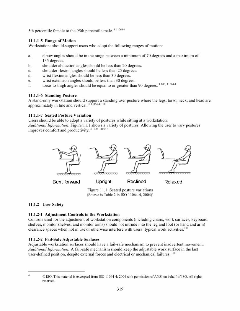
319
5th percentile female to the 95th percentile male. 3 11064-4 11.1.1-5 Range of Motion Workstations should support users who adopt the following ranges of motion: a. elbow angles should be in the range between a minimum of 70 degrees and a maximum of
135 degrees. b. shoulder abduction angles should be less than 20 degrees. c. shoulder flexion angles should be less than 25 degrees. d. wrist flexion angles should be less than 30 degrees. e. wrist extension angles should be less than 30 degrees. f. torso-to-thigh angles should be equal to or greater than 90 degrees. 3 100, 11064-4
11.1.1-6 Standing Posture A stand-only workstation should support a standing user posture where the legs, torso, neck, and head are approximately in line and vertical. 3 11064-4, 100 11.1.1-7 Seated Posture Variation Users should be able to adopt a variety of postures while sitting at a workstation. Additional Information: Figure 11.1 shows a variety of postures. Allowing the user to vary postures improves comfort and productivity. 3 100, 11064-4
Figure 11.1 Seated posture variations (Source is Table 2 in ISO 11064-4, 2004)4
11.1.2 User Safety 11.1.2-1 Adjustment Controls in the Workstation Controls used for the adjustment of workstation components (including chairs, work surfaces, keyboard shelves, monitor shelves, and monitor arms) should not intrude into the leg and foot (or hand and arm) clearance spaces when not in use or otherwise interfere with users’ typical work activities.100 11.1.2-2 Fail-Safe Adjustable Surfaces Adjustable workstation surfaces should have a fail-safe mechanism to prevent inadvertent movement. Additional Information: A fail-safe mechanism should keep the adjustable work surface in the last user-defined position, despite external forces and electrical or mechanical failures. 100
4 © ISO. This material is excerpted from ISO 11064-4: 2004 with permission of ANSI on behalf of ISO. All rights
reserved.
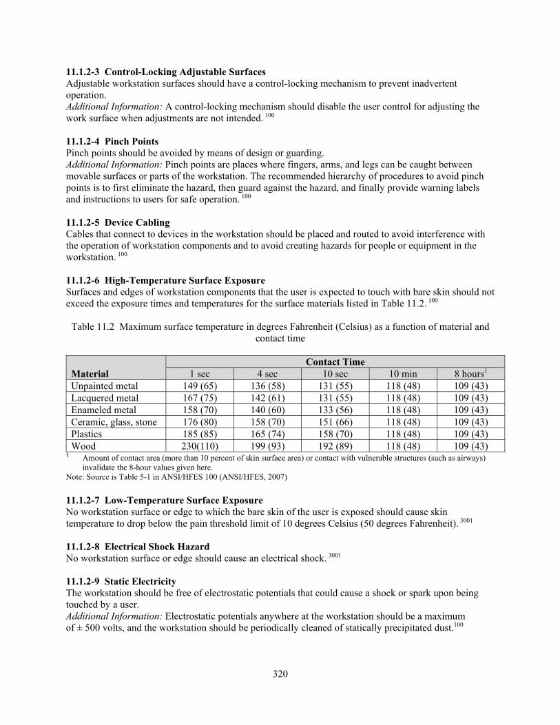
320
11.1.2-3 Control-Locking Adjustable Surfaces Adjustable workstation surfaces should have a control-locking mechanism to prevent inadvertent operation. Additional Information: A control-locking mechanism should disable the user control for adjusting the work surface when adjustments are not intended. 100 11.1.2-4 Pinch Points Pinch points should be avoided by means of design or guarding. Additional Information: Pinch points are places where fingers, arms, and legs can be caught between movable surfaces or parts of the workstation. The recommended hierarchy of procedures to avoid pinch points is to first eliminate the hazard, then guard against the hazard, and finally provide warning labels and instructions to users for safe operation. 100 11.1.2-5 Device Cabling Cables that connect to devices in the workstation should be placed and routed to avoid interference with the operation of workstation components and to avoid creating hazards for people or equipment in the workstation. 100 11.1.2-6 High-Temperature Surface Exposure Surfaces and edges of workstation components that the user is expected to touch with bare skin should not exceed the exposure times and temperatures for the surface materials listed in Table 11.2. 100
Table 11.2 Maximum surface temperature in degrees Fahrenheit (Celsius) as a function of material and contact time
Material Contact Time
1 sec 4 sec 10 sec 10 min 8 hours1 Unpainted metal 149 (65) 136 (58) 131 (55) 118 (48) 109 (43) Lacquered metal 167 (75) 142 (61) 131 (55) 118 (48) 109 (43) Enameled metal 158 (70) 140 (60) 133 (56) 118 (48) 109 (43) Ceramic, glass, stone 176 (80) 158 (70) 151 (66) 118 (48) 109 (43) Plastics 185 (85) 165 (74) 158 (70) 118 (48) 109 (43) Wood 230(110) 199 (93) 192 (89) 118 (48) 109 (43)
1 Amount of contact area (more than 10 percent of skin surface area) or contact with vulnerable structures (such as airways) invalidate the 8-hour values given here.
Note: Source is Table 5-1 in ANSI/HFES 100 (ANSI/HFES, 2007) 11.1.2-7 Low-Temperature Surface Exposure No workstation surface or edge to which the bare skin of the user is exposed should cause skin temperature to drop below the pain threshold limit of 10 degrees Celsius (50 degrees Fahrenheit). 3001 11.1.2-8 Electrical Shock Hazard No workstation surface or edge should cause an electrical shock. 3001 11.1.2-9 Static Electricity The workstation should be free of electrostatic potentials that could cause a shock or spark upon being touched by a user. Additional Information: Electrostatic potentials anywhere at the workstation should be a maximum of ± 500 volts, and the workstation should be periodically cleaned of statically precipitated dust.100

321
11.1.2-10 Sharp Corners and Edges for Large Equipment and Furniture Corners and edges of large fixed and handheld equipment located at or on the workstation, as well as large pieces of furniture (e.g., desks and tables), should be rounded as specified in Table 11.3. Additional Information: Radius is defined as the distance from the rounded surface to the center of the circle creating the arc. For surfaces that are not perfectly round or of constant radius, the minimum or smallest radius of the surface should be used. 3001, 100
Table 11.3 Corners and edges
Note: Source is Table 14 in NASA 3001, Volume 2 (NASA, 2011)
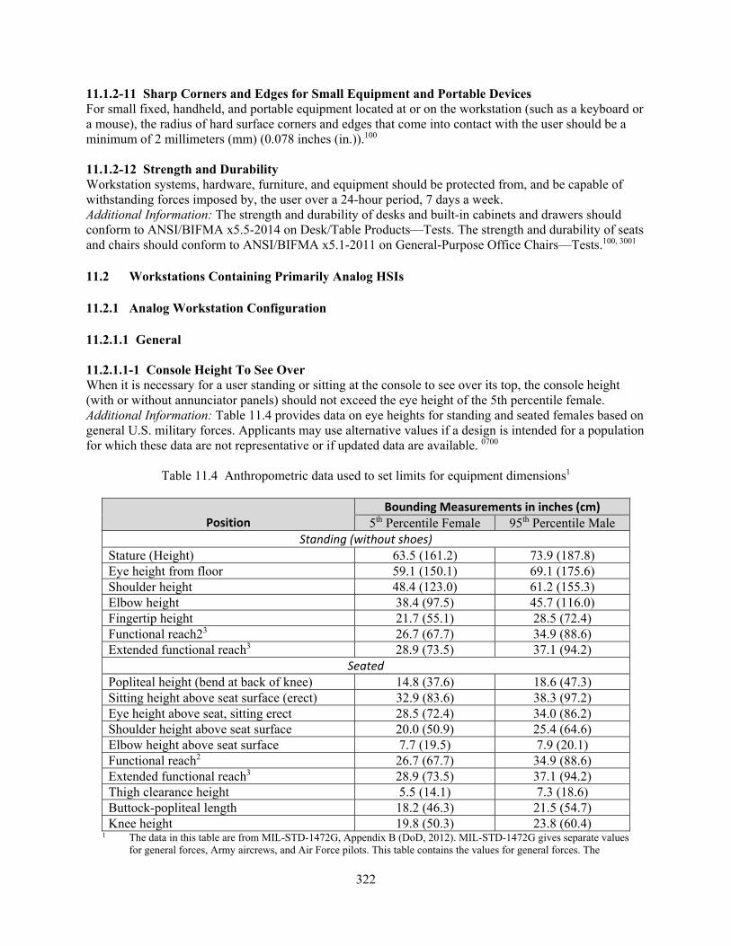
322
11.1.2-11 Sharp Corners and Edges for Small Equipment and Portable Devices For small fixed, handheld, and portable equipment located at or on the workstation (such as a keyboard or a mouse), the radius of hard surface corners and edges that come into contact with the user should be a minimum of 2 millimeters (mm) (0.078 inches (in.)).100 11.1.2-12 Strength and Durability Workstation systems, hardware, furniture, and equipment should be protected from, and be capable of withstanding forces imposed by, the user over a 24-hour period, 7 days a week. Additional Information: The strength and durability of desks and built-in cabinets and drawers should conform to ANSI/BIFMA x5.5-2014 on Desk/Table Products—Tests. The strength and durability of seats and chairs should conform to ANSI/BIFMA x5.1-2011 on General-Purpose Office Chairs—Tests.100, 3001 11.2 Workstations Containing Primarily Analog HSIs 11.2.1 Analog Workstation Configuration 11.2.1.1 General 11.2.1.1-1 Console Height To See Over When it is necessary for a user standing or sitting at the console to see over its top, the console height (with or without annunciator panels) should not exceed the eye height of the 5th percentile female. Additional Information: Table 11.4 provides data on eye heights for standing and seated females based on general U.S. military forces. Applicants may use alternative values if a design is intended for a population for which these data are not representative or if updated data are available. 0700
Table 11.4 Anthropometric data used to set limits for equipment dimensions1
Position Bounding Measurements in inches (cm)
5th Percentile Female 95th Percentile Male Standing (without shoes)
Stature (Height) 63.5 (161.2) 73.9 (187.8) Eye height from floor 59.1 (150.1) 69.1 (175.6) Shoulder height 48.4 (123.0) 61.2 (155.3) Elbow height 38.4 (97.5) 45.7 (116.0) Fingertip height 21.7 (55.1) 28.5 (72.4) Functional reach23 26.7 (67.7) 34.9 (88.6) Extended functional reach3 28.9 (73.5) 37.1 (94.2)
Seated Popliteal height (bend at back of knee) 14.8 (37.6) 18.6 (47.3) Sitting height above seat surface (erect) 32.9 (83.6) 38.3 (97.2) Eye height above seat, sitting erect 28.5 (72.4) 34.0 (86.2) Shoulder height above seat surface 20.0 (50.9) 25.4 (64.6) Elbow height above seat surface 7.7 (19.5) 7.9 (20.1) Functional reach2 26.7 (67.7) 34.9 (88.6) Extended functional reach3 28.9 (73.5) 37.1 (94.2) Thigh clearance height 5.5 (14.1) 7.3 (18.6) Buttock-popliteal length 18.2 (46.3) 21.5 (54.7) Knee height 19.8 (50.3) 23.8 (60.4)
1 The data in this table are from MIL-STD-1472G, Appendix B (DoD, 2012). MIL-STD-1472G gives separate values for general forces, Army aircrews, and Air Force pilots. This table contains the values for general forces. The

323
MIL-STD contains additional anthropometric data not represented in this table. Applicants may use alternative values if a design is intended for a population for which these data are not representative or if updated data are available.
2 Measured from wall to tip of right index finger, with arm extended horizontal to floor, both shoulders against wall. 3 Measured as stated above, except right shoulder extended as far as possible with left shoulder against wall.
11.2.1.1-2 Location of Controls Controls should be located within the reach radius of the 5th percentile female without stretching, while the lowest controls should be within the lowest reach of the 95th percentile male without bending or stooping. Additional Information: Table 11.4 provides data on reach for females and males. Controls may be placed somewhat higher on consoles with shallower or more steeply angled benchboards, which allow the shoulder reference point to be closer to the back of the benchboard and to the vertical panel.0700 11.2.1.1-3 Benchboard Slope The benchboard slope, in conjunction with its depth, should result in all controls being within the reach radius of the 5th percentile female (see Table 11.4) and in all displays and markings being read.0700 11.2.1.1-4 Minimum Distance of Controls from the Front Edge of the Console Controls should be set back a minimum of 7.6 cm (3 in.) from the front edge of the console to protect against accidental activation.0700 11.2.1.1-5 Location of Displays All displays, including alarm indicators, should be within the upper limit of the visual field (75 degrees above the horizontal line of sight (LOS)) of the 5th percentile female and the lower limit of the visual field of the 95th percentile male (see Table 11.4), and should be mounted so that the interior angle between the LOS and the display face is 45 degrees or greater (see Figure 11.2). Additional Information: The principal factors affecting the readability of displays, including annunciator tiles, are: (1) display height and orientation relative to the user’s LOS when positioned directly in front of the display, (2) display distance and orientation relative to the user’s straight-ahead LOS when the user must read the display from an off-side position, and (3) the size of display markings relative to the distance at which the display must be read. Section 1.3.1, “Alphanumeric Characters,” addresses character size, which is not considered here. Except as specifically noted, measurements of angles should be made with the eye point in line with the leading edge of the benchboard.0700
Figure 11.2 Line of sight
(Source is Figure 2 in MIL-STD-1472G, 2012)

324
11.2.1.1-6 Horizontal Viewing Angle for Important Displays Displays that require frequent or continuous monitoring, or that may display important (e.g., alarm) information, should be located not more than 35 degrees to the left or right of the user’s straight-ahead LOS. Additional Information: The preferred horizontal viewing angle is in the range between a minimum of minus 15 degrees and a maximum of plus 15 degrees. For workstations with multiple visual display screens arrayed in the horizontal dimension, this horizontal viewing angle may be expanded to a range between minus 60 degrees and plus 60 degrees for tasks where head rotation is allowed. 0700, 1472G 11.2.1.1-7 Writing Space on Consoles If writing space is needed, an area at least 40.6-cm (16-in.) deep and 70-cm (24-in.) wide should be provided, where these dimensions in the total configuration would fit users’ reach capabilities. Additional Information: Less space may be adequate considering the frequency and duration of writing requirements at control room consoles. If the console itself provides writing space, it should not interfere with viewing and the manipulation of controls and displays. If writing is necessary but space on the console is not available, other arrangements, such as a nearby desk or table, should be provided.0700 11.2.1.1-8 Use of Procedures and Other Reference Materials at Consoles Provision should be made so that the procedures, manuals, and other reference materials can be consulted easily while task sequences are performed at the consoles. Additional Information: Lack of space in which to lay down procedures can encourage the poor practice of placing them on the console. A rolling bookcase is a convenient place for storing procedures and manuals and provides space for laying down procedures during use.0700
11.2.1.2 Standup Workstations 11.2.1.2-1 Height Range for Controls Controls should be placed between 76 cm (30 in.) and 188 cm (70 in.) above the floor. 1472G 11.2.1.2-2 Height Range for Important Controls Emergency controls and those requiring precise or frequent operation should be placed in an area between 86 cm (34 in.) and 140 cm (55 in.) above the floor.1472G 11.2.1.2-3 Height Range for Displays Displays should be placed between 104 cm (41 in.) and 178 m (70 in.) above the floor. 1472G 11.2.1.2-4 Height Range for Important Displays Important displays and those that must be read frequently or precisely should be placed in an area between 140 cm (50 in.)and 165 cm (65 in.)above the floor. 1472G 11.2.1.2-5 Lateral Spread of Controls and Displays The maximum lateral spread of controls and displays at a single-user workstation should not exceed 183 cm (72 in.). Additional Information: The user should be able to perform task sequences at a given workstation with minimum repositioning. The amount of movement required depends on the arrangement of controls and displays, not simply on the lateral dimensions of the segments of the control board.0700 11.2.1.3 Sit-Only Workstations 11.2.1.3-1 Height Range for Controls Controls should be placed in an area between 20 cm (8 in.) and 86 cm (34 in.) above the sitting

325
surface.1472G 11.2.1.3-2 Height Range for Important Controls Emergency controls and those requiring precise or frequent operation should be placed in an area between 20 cm (8 in.) and 74 cm (29 in.) above the sitting surface.1472G 11.2.1.3-3 Height Range for Displays Displays should be placed in an area between 15 cm (6 in.) and 117 cm (46 in.) above the sitting surface. 1472G 11.2.1.3-4 Height Range for Important Displays Important displays and those that must be read frequently or precisely should be placed in an area between 36 cm (14 in.) and 89 cm (35 in.) above the sitting surface. 1472G 11.2.2 Panel Layout 11.2.2.1 General Panel Layout 11.2.2.1.1 Assignment of Panel HSIs 11.2.2.1.1-1 Grouping by Task Controls and displays should be assigned to workstations based on the tasks the user must carry out. Additional Information: To the extent practical, this assignment should consider both normal and emergency procedures. It should be practical to perform all frequently occurring routine tasks, and time-sensitive emergency tasks, with a minimum of movement from panel to panel.0700 11.2.2.1.1-2 Grouping by System Function Within the constraints of grouping by task sequence, controls and displays should be assigned to panels in functional groups related to system structure. Additional Information: This grouping should promote easy understanding of the relationship between controls and systems and should assist the graphic or pictorial display of system relationships.0700 11.2.2.1.1-3 Grouping by Importance and Frequency of Use Controls and displays should be assigned to panels depending on their importance and frequency of use, within the constraints of grouping by task sequence and system function.0700 11.2.2.1.1-4 Less Important Controls and Displays Controls or displays that are neither important to plant safety nor frequently used should be installed in ancillary panel locations.0700 11.2.2.1.2 Enhancing Recognition and Identification 11.2.2.1.2-1 Spacing Spacing between groups should be at least the width of a typical control or display in the group. Additional Information: Spacing consists of physically separating groups of components on a panel with enough space between groups so that the boundaries of each group are obvious.0700 11.2.2.1.2-2 Color Shading When color shading is used, colors should provide adequate contrast and should be consistent with other color coding in the control room.0700

326
11.2.2.1.2-3 Emergency Controls Distinctive techniques should be used to enhance the recognition and identification of emergency controls. Additional Information: For example, a unique style of demarcation or color shading might be applied exclusively to emergency controls.0700
11.2.2.2 Layout Arrangement Factors 11.2.2.2-1 Sequence Controls and displays should be grouped together when they are observed or operated in a specified sequence. Additional Information: Controls and displays should be positioned so that they are normally used in a left-to-right, top-to-bottom, or other natural sequence.0700 11.2.2.2-2 Frequency of Use Frequently used controls and displays should be near the center of the preferred visual and manual areas.0700 11.2.2.2-3 Functional Considerations Functionally related controls and displays should be grouped together when they are used together to perform tasks related to a specific function or are identical in purpose.0700 11.2.2.2-4 Order and Labeling Components should be arranged left to right or top to bottom, or both, and identified in alphabetic or numeric sequence. Additional Information: For example, four related displays in a row should be designated A, B, C, D or 1, 2, 3, 4; correspondingly, any controls related to these displays should also be designated A, B, C, D or 1, 2, 3, 4.0700 11.2.2.2-5 User Expectations Components should be arranged to match user expectations. Additional Information: Well-designed system mimics will help direct and satisfy user expectations.0700 11.2.2.2-6 Inter- and Intra-Panel Consistency The location of arrangement of recurring functional groups and individual components of those groups should be similar from panel to panel or within a panel.0700 11.2.2.2-7 Repeated Functions The layout of identical control or display sets should be consistent at all locations.0700 11.2.2.2-8 Mirror-Imaging Layouts of repeated functions should not be mirror imaged (see Figure 11.3).0700

327
Figure 11.3 Example of a mirror-image arrangement of controls and displays 11.2.2.2-9 Panel-to-Panel Standardization Standardization should be maintained where similar functions or panels are located at several workstations or units.0700 11.2.2.2-10 Simulator-to-Control Room Standardization Standardization should be maintained where simulator or procedures trainers are used that simulate the actual operational equipment.0700 11.2.2.3 Specific Panel Layout Design 11.2.2.3.1 Separation of Controls 11.2.2.3.1-1 Access Control access should not be impeded by any position of an adjacent control. Additional Information: Figure 11.4 and Table 11.5 show recommended minimum separation distances for controls. In most cases, control room operations will require greater separation.0700
Figure 11.4 Measurement of minimum separation between controls
(distances shown in Table 11.5)

328
Table 11.5 Minimum separation distances for controls (see Figure 11.4)
Type of Control
Minimum Separation in inches and (mm)
Key- operated controls
Pushbuttons Pushbutton arrays
Legend switches
Slide switches,
rocker switches
Toggle switches
Thumb-wheels
Rotary selector switches
Continuous rotary
controls
J-handles (large)
J-handles (small)
Key-operated Controls
1.0 (25)
0.5 (13)
1.5 (38)
1.0 (25)
0.75 (19)
0.75 (19)
0.5 (13)
0.75 (19)
0.75 (19)
5.0 (127)
2.0 (50)
Pushbuttons 0.5 (13)
0.5 (13)
2.0 (50)
2.0 (50)
0.5 (13)
0.5 (13)
0.5 (13)
0.5 (13)
0.5 (13)
6.0 (152)
3.0 (76)
Pushbutton arrays1
1.5 (38)
2.0 (50)
2.0 (50)
2.0 (50)
1.5 (38)
1.5 (38)
1.5 (38)
2.0 (50)
2.0 (50)
6.0 (152)
3.0 (76)
Legend switches2
1.0 (25)
2.0 (50)
2.0 (50)
2.0 (50)
1.5 (38)
1.5 (38)
1.5 (38)
2.0 (50)
2.0 (50)
6.0 (152)
3.0 (76)
Slide switches, rocker switches
0.75 (19)
0.5 (13)
1.5 (38)
1.5 (38)
0.5 (13)
0.75 (19)
0.5 (13)
0.5 (13)
0.5 (13)
5.0 (127)
2.0 (50)
Toggle switches3
0.75 (19)
0.5 (13)
1.5 (38)
1.5 (38)
0.75 (19)
0.75 (19)
0.5 (13)
0.75 (19)
0.75 (19)
6.0 (152)
3.0 (76)
Thumbwheels 0.5 (13)
0.5 (13)
1.5 (38)
1.5 (38)
0.5 (13)
0.5 (13)
0.5 (13)
0.75 (19)
0.75 (19)
5.0 (127)
2.0 (50)
Rotary selector switches
0.75 (19)
0.5 (13)
2.0 (50)
2.0 (50)
0.5 (13)
0.75 (19)
0.75 (19)
1.0 (25)
1.0 (25)
5.0 (127)
2.0 (50)
1 Pushbuttons within an array, 19 cm (0.75 in.) center to center. 2 Legend switches within an array, no minimum distance, but should be separated by a barrier. Barrier should be at least 0.125-in. wide, 0.183-in. high, with rounded
edges. Legend switches manufactured as elements of a module or modular array may be mounted as closely as engineering consideration permits. 3 Toggle switches arrayed in a horizontal line, 19 cm (0.75 in.) center to center
328

329
11.2.2.3.1-2 Inadvertent Actuation Control actuation should not result in inadvertent actuation of an adjacent control.0700 11.2.2.3.1-3 Simultaneous Actuation It should be possible to simultaneously actuate adjacent controls (where required).0700 11.2.2.3.2 Strings or Clusters of Similar Components 11.2.2.3.2-1 Orientation Horizontal rows of displays should be used rather than vertical columns.0700 11.2.2.3.2-2 String Length Strings of similar small displays should not exceed 51 cm (20 in.) on the control board.0700 11.2.2.3.2-3 Number of Components No more than five similar components should be laid out in an unbroken row or column. Additional Information: If more than five similar components must be laid out together, the string or cluster should be broken up by techniques such as physical spacing or demarcation.0700 11.2.2.3.2-4 Coordinate Axes for Matrices Large matrices of similar components should have the coordinate axes labeled for identification of any single component within the grid.0700 11.2.2.3.2-5 Labeling Large Matrices The left and top sides of large matrices should be used for labeling.0700 11.2.2.3.2-6 Demarcation of Large Matrices Large matrices should be subdivided by appropriate demarcation.0700 11.2.3 Control-Display Integration 11.2.3.1 Basic Control Display Relationships 11.2.3.1.1 Single Control and Display Pairs 11.2.3.1.1-1 Proximity A visual display that will be monitored during control manipulation should be located sufficiently close that a user can read it clearly and without parallax from a normal operating posture.0700 11.2.3.1.1-2 Obscuration Controls and displays should be located so that displays are not obscured during control operation. Additional Information: To avoid having the user’s hand obscure the display, controls should be located below the associated display (see “B” in Figure 11.5). When this is not possible, the control should be located to the right of the display (see “A” in Figure 11.5). 0700

330
Figure 11.5 Position of control actuator and associated display 11.2.3.1.1-3 Association Related controls and displays should be easily identified as being associated. Additional Information: This association can be established (or enhanced) by (1) location, (2) labeling, (3) coding, (4) demarcation, and (5) consistency with user expectations. The following relationships should be immediately apparent to the user: (1) association of displays with controls, (2) the direction of movement of control and display, and (3) the rate and limits of movement of the control and display. See Figure 11.6.0700
Figure 11.6 Association by grouping 11.2.3.1.2 Multiple Controls and a Single Display 11.2.3.1.2-1 Controls Mounted Below Display Multiple controls should be mounted below the single display.0700 11.2.3.1.2-2 Alternative Control Position If it is not feasible to mount multiple controls directly below the single display, controls should be mounted to the right of the display.0700 11.2.3.1.2-3 Controls Centered on Display Multiple controls should be centered on the single display.0700

331
11.2.3.1.2-4 Grouping of Controls Multiple controls should be grouped in a line or matrix.0700 11.2.3.1.2-5 Arrangement of Controls Where there is a normal order of use, multiple controls should be arranged for use in a left-to-right, top-to-bottom, or other natural sequence.0700 11.2.3.1.2-6 Enhancement of Control Layout Layout enhancement techniques should be employed where the above techniques cannot apply, or where, for other reasons, the relationships are not readily apparent.0700 11.2.3.1.3 Single Control and Multiple Displays 11.2.3.1.3-1 Displays Located Above Control Multiple displays should be located above the single control.0700 11.2.3.1.3-2 Alternative Position for Displays If it is not feasible to mount multiple displays above the single control, they should be mounted to the left of the control.0700 11.2.3.1.3-3 Control Centered Below Displays The single control should be placed as near as possible to the display and preferably underneath the center of the display array.0700 11.2.3.1.3-4 Grouping of Displays Multiple displays should be arranged horizontally or in a matrix.0700 11.2.3.1.3-5 Arrangement of Displays Where there is a normal order of use, multiple displays should read from a left-to-right, top-to-bottom, or other natural sequence.0700 11.2.3.1.3-6 Visibility During Control Manipulation Multiple displays should not be obscured during control manipulation.0700 11.2.3.1.3-7 Enhancement of Display Layout Layout enhancement techniques should be employed where the above techniques cannot apply, or where, for other reasons, the control-display relationship is not clearly apparent.0700 11.2.3.1.4 Display Selectors 11.2.3.1.4-1 Display Selector Motion The display selector control should move clockwise from OFF (if appropriate) through settings 1, 2, 3...n. Additional Information: This guideline applies to rotary selector switches used to select displays for viewing. 0700 11.2.3.1.4-2 Display Selector Sequence The display selector control position sequence should conform to the display sequence.0700 11.2.3.1.4-3 Display Selector Labeling Display selector control position indications should correspond to display labels.0700

332
11.2.3.1.4-4 Display Selectors Scale Displays should read off scale, not zero, when not selected, especially if zero is a possible parameter displayed.0700 11.2.3.2 Groups of Controls and Displays 11.2.3.2-1 Functional Grouping Multiple controls or displays related to the same function should be grouped together.0700 11.2.3.2-2 Sequence of Use Sequence of use should be as follows: (1) left to right, (2) top to bottom, or (3) both combined (normal reading order).0700 11.2.3.2-3 Display Above Each Control The preferred configuration is with the display above each control. Additional Information: If this configuration is used, the following should apply: (1) each display should be located directly above its associated control, and (2) the display or control pairs should be arranged in rows.0700 11.2.3.2-4 Controls and Displays in Rows Displays may be arrayed in rows as the upper portion of a panel, matched to controls arrayed in similar rows below (see Figure 11.7). Additional Information: Each control should occupy the same relative position as the display to which it is associated. Controls and displays should have corresponding labels.0700
Figure 11.7 Controls and displays in rows 11.2.3.2-5 Multirow Displays with Single-Row Controls Two or more rows of displays may be arranged above a single row of controls (see Figure 11.8). Additional Information: Displays should be ordered left to right and top to bottom (in normal reading order), and matched to controls ordered left to right. Controls and displays should have corresponding labels.0700

333
Figure 11.8 Two rows of displays with a single row of controls 11.2.3.2-6 Consistent Practice Arrangements of functionally similar controls and displays should conform to the same convention throughout the control room.0700 11.2.3.2-7 Control/Display Packages Modules should be selected and arranged to achieve maximum conformity with the principles described above. Additional Information: When controls and related displays are assembled using modular packaged units, the design of the packages will limit the location and arrangement that can be achieved.0700 11.2.3.2-8 Separated Controls and Displays Where displays are on separated panels, they should be on the adjacent upper panel with their associated controls.0700 11.2.3.2-9 Facing Panels Related controls and displays should not be located on separate panels that face each other.0700 11.2.3.3 Dynamic Control-Display Relationships 11.2.3.3-1 Rotary Controls Rotary controls should turn clockwise to cause an increase in parameter value. Associated display movements should be: (1) analog scales, up or to the right, (2) digital displays, increasing in value, (3) strings of indicator lights, bottom to top or left to right, and (4) circular meter pointers, clockwise.0700 11.2.3.3-2 Linear Controls Linear controls should move up or to the right to cause an increase in parameter value. The associated display relationships should be: (1) analog scales, up or to the right, (2) digital displays, increasing in value, and (3) strings of indicator lights, bottom to top or left to right.0700
334
11.2.3.3-3 Display Response Time Lag When there is a time lag between control actuation and the ultimate system state, there should be an immediate feedback indication of the process and direction of parameter change. Additional Information: In some cases, there will be a time lag between the actuation of a control and the resulting change in the system condition. That condition should be reflected by displays in real time.0700 11.2.3.3-4 Precision of Control Controls should provide a capability to affect the parameter controlled easily, with the required level of precision. Additional Information: They should be effective in sufficient time; under expected dynamic conditions; and within the limits of manual dexterity, coordination, and reaction time.0700 11.2.3.3-5 Resolution of Display Displays should provide a capability to distinguish significant levels of the system parameter controlled.0700 11.2.3.3-6 Excess Precision The precision of displays and controls should not greatly exceed that required.0700 11.2.3.3-7 Feedback Feedback from the display should be apparent for any deliberate movement of a control.0700 11.3 Workstations Containing Primarily Computer-Based HSIs 11.3.1 Visual Display Devices 11.3.1.1 General 11.3.1.1-1 Design of Visual Display Device(s) The visual display device(s) should be designed so that it (they) may be viewed and read to the required degree of accuracy by all necessary personnel in normal operating and maintenance postures and at typical viewing distances.1472G 11.3.1.1-2 Number, Size, and Resolution of Visual Display Device To Support Task Demands The number of display devices, screen sizes, and resolution should be sufficient to support all work tasks that must be performed concurrently. Additional Information. The display screen size of a single device is usually measured by the diagonal length of the visual display image area (e.g., 76 cm (30 in.) and the display screen resolution is usually measured by the number of linear pixels in the horizontal and vertical dimensions of the image area (e.g., 1920x1080).5 6546, 11064-4 11.3.1.1-3 Number of Visual Display Devices To Minimize Workload The number of display devices provided in the workstation should be sufficient to maintain interface management demands at a level that does not impair user performance. Additional Information: The number of display devices should not be so high that the devices cannot fit within the recommended viewing areas of workplace design and, thus, cannot be easily monitored or operated effectively by the users. However, the number of display devices should not be so low that the
5 © ISO. This material is excerpted from ISO 11064-4: 2004 with the permission of ANSI on behalf of ISO. All rights
reserved.
335
interface management demands required for accessing and using displays detracts from the user’s overall performance on primary tasks.0700 11.3.1.2 Relationship to Viewer (Viewing Angles and Distances) 11.3.1.2 -1 Vertical Viewing Angle The vertical viewing angle from the eye point of the user to the center of the visual display image area should be in the range between minus 40 degrees and 0 degrees relative to the horizontal LOS. Additional Information: Preferably, the center of the visual display screen image area should be located between a minimum of minus 25 degrees and a maximum of minus 15 degrees vertical relative to the eye point of the user in the normal working posture. The location of the visual display device should be measured relative to the eye point of the user. For convenience in measuring viewing angles and distances, the bridge of the nose may be substituted as a reference location for the eye point of the user.6
100, 9241-303 11.3.1.2-2 Horizontal Viewing Angle The horizontal viewing angle from the eye point of the user to the center of the visual display image area should be in the range between a minimum of minus 35 degrees and a maximum of plus 35 degrees, measured in the horizontal plane relative to direct, frontal perpendicular viewing. Additional Information: The preferred horizontal viewing angle is in the range between a minimum of minus 15 degrees and a maximum of plus 15 degrees. For workstations with multiple visual display screens arrayed in the horizontal dimension, this horizontal viewing angle may be expanded to a range between minus 60 degrees and plus 60 degrees for tasks where head rotation is allowed. 100, 1472G 11.3.1.2-3 Minimum Viewing Distance Under normal control room viewing conditions, the viewing distance from the eye point of the user to the center of the visual display image area should be a minimum of 50 cm (19.7 in.). Additional Information. For short observation periods and for dim display images, the viewing distance may be reduced to a minimum of 25 cm (10 in.). 100, 1472G 11.3.1.2-4 Large Viewing Distances Display screens that must be viewed from distances greater than 50 cm (19.7 in.) should be appropriately modified in aspects such as display size, symbol size, brightness ranges, and resolution.1472G 11.3.1.2-5 Orientation of Display Screen Face The orientation of the screen visual display face should preferably be perpendicular (90 degrees) relative to the normal straight-ahead LOS of the user. If this is not possible, the angle of the visual display screen face should be a minimum of 45 degrees in any direction relative to the normal LOS. 1472G 11.3.1.3 Relationship to Lighting Environment (Reflections and Glare) 11.3.1.3-1 Reflections and Glare Glare should not interfere with the readability of the displays, labels, or indicators on the display device. Additional Information: The visual display screen and surrounding visible area of the device housing should not produce disturbing or debilitating reflections or glare from the environmental lighting or other external light sources. This is especially important for prolonged viewing tasks. Reflections of ambient light sources (e.g., luminaires, lamps, windows) on a display screen can be disturbing or debilitating
6 © ISO. This material is excerpted from ISO 9241-303: 2011 with the permission of ANSI on behalf of ISO. All rights
reserved.

336
(reducing task performance). Depending on the kind of visual display device, and the display technology employed, reflections can be one of the following types or combinations thereof: • Lambertian (reflected luminance constant over all directions, uniform across the screen)
• specular on one part of the screen (mirror-like, a distinct image of the source of illumination may
be visible)
• haze (peaked about the specular direction, but images are blurred because of light scattering) See IDMS (2012) for measurement information.7 0700, 9241-303 11.3.1.3-2 Contrast Ratio (Specular) The display device should be capable of producing a legible and interpretable image on the screen, even at the location of specular reflection on the screen from a bright, glaring light source in the environment. Additional Information: The contrast ratio of the visual display screen should be a minimum of 3:1 under specular illumination from a 1,000 candelas per square meter (cd/m2) (29 foot-lamberts (ft-L)) source subtending 15 degrees. See IDMS (2012) for measurement information.100 11.3.1.3-3 Contrast Ratio (Ambient) The display device should be capable of producing a legible and interpretable image on the screen, even at the highest level of overall ambient illumination in the environment. Additional Information: The visual display screen contrast ratio should be a minimum of 3:1 under ambient illumination of 1,000 lux (lx) (93 foot-candles (fc)) (Lambertian glare). See IDMS (2012) for measurement information.100 11.3.1.3-4 Contribution from Ambient Illumination The display device should be capable of producing a screen image that does not appear to be washed out by the ambient illumination in the environment. Additional Information: The ambient illumination contribution to the visual display screen should be a maximum of 25 percent of the overall screen luminance caused by reflection. See IDMS (2012) for measurement information.1472G 11.3.1.3-5 Shields or Filters—Antiglare Treatment If necessary, the display screen or the light source should have antiglare or antireflection treatment, or both. Additional Information: A shield or filter on the display screen or on the light source can reduce glare. If glare reduction or contrast enhancement techniques are used, the resultant visual display should not violate the requirements of spatial and temporal properties, nor luminance and color for display devices without such techniques applied.7 9241-303, 5908, 0700 11.3.1.4 Display Screen Performance Measurement Parameters 11.3.1.4.1 Screen Spatial Properties 11.3.1.4.1-1 Display Screen Resolution The display device screen should have sufficient resolution so users can distinguish all display elements, 7 © ISO. This material is excerpted from ISO 9241-303: 2011 with the permission of ANSI on behalf of ISO. All rights
reserved.
337
characters, images, and codes from the maximum viewing distance and angle. Additional Information: One measure of display resolution is the number of pixels along the width and height of the visual display screen (e.g., 1024x600). For a given viewing distance, the more pixels along each dimension, the better the display screen resolution. For image and video displays, the screen resolution should be a minimum of 32 pixels per degree of visual angle. The modulation transfer function area (MTFA) is a more accurate measure of display screen resolution; it should be a minimum of 5. This value may be directly developed from microphotometric measurements; or, for monochrome visual displays, it may be estimated using a formula, which may be found in the cited reference. See IDMS (2012) for measurement information.5908, 3001 11.3.1.4.1-2 Display Screen Contrast The contrast ratio of the display screen should be a minimum of 6:1; a contrast ratio of 10:1 is preferred. Additional Information: Modern visual display devices can have considerably higher stated contrast ratio capability than 10:1, but glare and reflections can substantially reduce the actual contrast ratio of the screen. This contrast ratio should include any contributions caused by ambient light, reflections, or glare on the display screen. Either display polarity (i.e., dark characters on a light background or light characters on a dark background) is acceptable, provided it meets the guidance for display screen resolution (above) and screen luminance. When ambient illumination near the display screen is high (greater than or 540 lx, or 50.2 fc), dark characters on a light background should be used. The contrast ratio (CR) is calculated as follows:
CR = Lmax / Lmin,
where Lmax is the higher luminance of the background or of the character, and Lmin is the lower luminance of the two. These values include the contribution from ambient light. Small characters (i.e., characters between 10 and 17 minutes of arc) should have a minimum luminance modulation (M) of:
M = 0.3 + 0.07 (20 - S),
where S is the vertical size of the character set, in minutes of arc, and Luminance modulation is calculated M = (Lmax-Lmin)/(Lmax + Lmin). See IDMS (2012) for measurement information. 5908, 0700, 1472G, 100 11.3.1.4.1-3 Display Screen Contrast Uniformity Display screen image contrasts that are supposed to be the same at different locations on the screen should appear the same. Additional Information: Contrast uniformity can be important if proper recognition or presentation of information depends critically on proper scene or pattern rendering. It is expressed as a percentage: contrast (C) uniformity = 100 % (Cmin / Cmax), where Cmin and Cmax are the minimum and maximum contrast, respectively, of the sampled contrast set on the screen. The contrast uniformity should be as high as possible and, in general, should be commensurate to the user’s task. See IDMS (2012) for measurement information.8 9241-303 11.3.1.4.1-4 Display Image Continuity The display image should appear to users as a continuous image (i.e., users should not be able to resolve scan lines, matrix spots, gaps, or individual pixels. Additional Information: This applies whether the raster is scanned or directly addressed. 5908 8 © ISO. This material is excerpted from ISO 9241-303: 2011 with the permission of ANSI on behalf of ISO. All rights
reserved.
338
11.3.1.4.1-5 Display Image Nonlinearity The display image should be free of geometric nonlinearity distortion. Additional Information: For different rows or columns of text, the difference of length should be a maximum 1.0 percent of the intended length of that column or row. For a more fine-grained determination of linearity, the horizontal displacement of a symbol position relative to the symbol positions directly above and below that symbol position, should be a maximum of 5.0 percent of the symbol box width. The vertical displacement of a symbol position, relative to the symbol positions to the right and left of the symbol position, should be a maximum of 5.0 percent of that symbol box height. Lines and columns should be parallel and orthogonal one to the other within the limits of the linearity requirement. This may be expressed as:
0.04 (Shorter edge/Longer edge) >= Diag1/Diag2—1.
The variation in size of a specific symbol anywhere on the display should be a maximum of 10 percent, regardless of its location within the image area. This is expressed as follows:
2(h2 - h1) / (h2 + h1) <= 0.1, and 2(w2 - w1)/(w2 + w1) < 0.1,
where h is the height of the symbol and w is the width of the symbol. When all the character positions on the screen are filled with “H”s or “M”s of the same character set, h1 is the height of the smallest character, h2 is the height of the largest character, w1 is the width of the smallest character, and w2 is the width of the largest character.9 5908, 9241-303 11.3.1.4.1-6 Display Image Orthogonality Display image elements that are intended to be perpendicular should appear to be perpendicular. Additional Information: Graphic orthogonality error should be a maximum of plus or minus 30 minutes of arc (about a 1-percent orthogonality error). See IDMS (2012) for measurement information.100 11.3.1.4.1-7 Display Screen Pixel Properties The pixel properties of the screen should produce no visible granularity, roughness, fuzziness, gaps, or jagged lines. Additional Information: The clarity and legibility of the image on the display device screen are heavily dependent upon the pixel properties of the screen. The following are several important pixel properties that contribute to image clarity and legibility:
• For CRT visual display devices, the pixel size should be a minimum of 0.2 mm at half height.
• For displays having a pixel density of fewer than 30 pixels per degree of visual angle at the design viewing distance, the pixel grid modulation should be a maximum of 0.4 for monochrome, and a maximum 0.7 for multicolor displays when all pixels are at maximum luminance.
• For flat-panel displays having a pixel density of fewer than 30 pixels per degree of visual angle at the design viewing distance, the fill factor should be minimum of 0.3 and preferably a minimum of 0.5.
• Pixel pitch, the distance between adjacent pixels from center to center, is determined by the design viewing distance, the height of characters in number of pixels, and the height of characters
9 © ISO. This material is excerpted from ISO 9241-303: 2011 with the permission of ANSI on behalf of ISO. All rights
reserved.
339
in visual angle. For example, if the design viewing distance is 50 cm, the pixel pitch must be 0.25 mm for characters 16 arc minutes high, and 0.35 mm for characters 22 arc minutes high. The pixel pitch should be a maximum of 0.3 mm/pixel .
• The manufacturer of the display device should specify a Classpixel for the display. The display should be free of pixel and subpixel faults according to its Classpixel.
See IDMS (2012) for measurement information.100 11.3.1.4.1-8 Moiré Patterns The screen image should be free of Moiré patterns when observed over the range of anticipated viewing distances and angles. Additional Information: Moiré patterns are unwanted periodic patterns in or around the intended image on the screen. They can appear as ripples, waves, and intensity variations that are superimposed on the screen image. Such periodic patterns are easily noticed by observers and tend to mask the displayed information. Moiré patterns can occur when the image represented contains spatial frequencies with periods less than twice the distance between adjacent pixels. In an approximation, the contrast of the fundamental spatial frequency of such patterns should be a maximum of 0.07 over the range of spatial frequencies from 0.5 to 7 cycles per degree of visual angle, where contrast = (Lmax—Lmin) / (Lmax + Lmin), for the luminances (L) of the Moiré pattern. The maximum allowable contrast then rises approximately linearly from a value of 0.07 to a value of about 1.0 over the range of spatial frequencies from 7 to 12 cycles per degree of visual angle. The cited reference gives a more precise relationship between maximum contrast and spatial frequency. See IDMS (2012) for measurement information.10 100,
9241-303 11.3.1.4.2 Screen Temporal Properties 11.3.1.4.2-1 Display Response Time The response time of the visual display device should be sufficiently short to avoid decreasing the contrast of rapidly changing images, especially those that move across the screen, and to avoid leaving afterimages and visible trails behind moving objects. Additional Information: The response time of the visual display device is the time required for luminance changes to pass through 90 percent of an intended instantaneous change. The response time should be a maximum of 55 milliseconds (ms); it should also be less than the duration of a single frame. In general, the response time should be a maximum of 13 ms for a refresh rate of 75 frames/second (sec). See IDMS (2012) for measurement information.100 11.3.1.4.2-2 Display Flicker The display should be free of detectable flicker. Additional Information: Flicker is the perception of unintended temporal variations in luminance on the display, in a frequency range of a few hertz (Hz) up to the critical flicker frequency. These unintended temporal variations can affect the comfort and performance of the user. The regeneration rate of the visual display device should be above the critical frequency for fusion so that flicker is not perceptible. See IDMS (2012) for measurement information.10 5908, 0700, 9241-303 11.3.1.4.2-3 Display Jitter The display should be free of geometric instability or “jitter.” 10 © ISO. This material is excerpted from ISO 9241-303: 2011 with permission of ANSI on behalf of ISO. All rights
reserved.
340
Additional Information: Jitter is unwanted peak-to-peak variation in the geometric location of pixels over time. The image on the display screen should not jump around or oscillate in any dimension to a degree that the user would notice from the normal range of viewing angles and distances. Jitter should be a maximum of 0.0002 times the design viewing distance in the frequency range from 0.5 Hz to 30 Hz. Variations in the geometric location of a picture element should be a maximum of 0.0002 mm per mm (0.0002 in. per in.) of viewing distance over a period of 1 second. This may be expressed as
VD x 0.0002 >= (H² + V²)0.5,
where VD is the viewing distance and H and V are the maximum excursions of picture element centers, horizontally and vertically.0700 For displays viewed from a great distance, over a 1-second period, the movement of an intended stationary picture element should be a maximum of 0.2 milliradians (41 seconds) of visual angle. See IDMS (2012) for measurement information.5908, 100, 1472G 11.3.1.4.2-4 Moving Edge Blur The edges of moving objects in display images should not appear blurred. Additional Information: Moving edge blur should be a maximum of 15 ms. Moving edge blur should be measured by means of blur edge time, or by means of Gaussian edge time. See IDMS (2012) for measurement information.3001 11.3.1.4.2-5 Other Display Instabilities Unintended spatial or temporal artifacts that exceed the threshold for visual detection should be minimized. Additional Information: Electronic visual displays can exhibit other unintended spatial and temporal luminance variations such as “swim” or “crosstalk.”11 9241-303
11.3.1.4.3 Screen Luminance 11.3.1.4.3-1 Display Luminance The display should have adequate luminance over the range of expected ambient illumination. Additional Information: The luminance of either the character or its background, whichever is of higher luminance, should be a minimum of 35 cd/m² (10 ft-L), preferably a minimum of 100 cd/m2 (29 ft-L). The preferred display luminance range should be between a minimum of 80 cd/m2 (23 ft-L) and a maximum of 160 cd/m² (47 ft-L). Some modern displays are capable of producing a considerably higher luminance than 160 cd/m² (47 ft-L). See IDMS (2012) for measurement information.5908, 0700, 100 11.3.1.4.3-2 Display Image Luminance Uniformity Display screen image luminances that are supposed to be the same at different locations on the screen should appear the same. Additional Information: In normal ambient illumination, for an intended uniform display luminance, the luminance nonuniformity, either stepwise or smooth, should not exceed the threshold for reduced visual performance. Luminance nonuniformity, the variation from the center to the edge of the display, should be a maximum 50 percent of the center luminance. Unintended luminance variations, within half a degree of arc, calculated from the design viewing distance anywhere on the display, should be a maximum of 50 percent. These measurements should be made in a dark room. See IDMS (2012) for measurement information.11 5908, 0700, 9241-303 11 © ISO. This material is excerpted from ISO 9241-303: 2011 with permission of ANSI on behalf of ISO. All rights
reserved.

341
11.3.1.4.3-3 Display Luminance Adjustment Range The display screen should have an adjustable luminance range to accommodate anticipated differences in ambient illumination. Additional Information: The display screen luminance should be adjustable, and the range of adjustment should be a minimum 10:1, preferably 50:1. See IDMS (2012) for measurement information. 0700, 1472G 11.3.1.4.3-4 Gamma and Gray Scale Shadows should not appear to be washed out or excessively dark. Additional Information: The gamma for each of these three primary colors should be in the range between a minimum of 1.8 and a maximum of 2.2. The number of discreet gray scale levels should be a minimum of 256. See IDMS (2012) for measurement information.11 9241-303, 3001 11.3.1.4.4 Screen Colors 11.3.1.4.4-1 Color Set The visual display device should be capable of producing colors that can be readily distinguished for color coding purposes. Additional Information: The minimum set should include red, green, blue, yellow, brown, orange, pink, purple, black, grey, and white. 100 11.3.1.4.4-2 Color Gamut The visual display device should be capable of producing a wide variety of colors and color combinations to render graphic images, maps, pictures, diagrams, photographs, and video images with sufficient realism and accuracy to support all required user tasks. Additional Information: Accurate color rendering is necessary whenever objects or scenes taken from reality are seen on a visual display. Inadequate color rendering can cause misinterpretation or missing recognition of the objects or scenes that are visualized (e.g., the inaccurate color of a chemical solution may mask actual contamination in the solution). The color gamut should be triangular, and the area of the color gamut should be a minimum of 50 percent of the area of a given chromaticity diagram. For visual display devices used for images and videos, the number of colors that can be displayed should be a minimum of 224, or 1,627,716, colors and their combinations. See IDMS (2012) for measurement information.3001, 100 11.3.1.4.4-3 Color Uniformity Display screen image colors that are supposed to be the same should appear the same at different locations on the screen. Additional Information: Color uniformity refers to how well the color remains constant over the surface of the screen. When a color is intended to be uniform over a certain area of the screen image, the chromaticity differences of that color in color space, Du’v’, at different locations in that intended image area, should be a maximum of 0.03 in general, and a maximum of 0.02 within any area subtending less than 35 percent of visual angle. See IDMS (2012) for measurement information.100
11.3.1.4.4-4 Color Convergence Image objects on the display screen should not have color fringes or double color images along the edges of the object at any location on the screen. Additional Information: On multicolor shadow-mask cathode ray tube (CRT) displays and on projected images from some projector technologies, color misconvergence can cause the appearance of color fringes or double images and may reduce user performance. The level of misconvergence at any location on such CRT displays or projection screens should not degrade visual performance in executing necessary

342
tasks. See IDMS (2012) for measurement information.12 9241-303 11.3.1.4.4-5 Reference White Images of white-colored surfaces, such as white paper or white clothing, should be perceived as “white,” regardless of the illumination at the scene that is being reproduced. Additional Information: To produce authentic color sensations (i.e., those corresponding to the expectation of a user watching a reproduction of reality), it is desirable to have images of nonselective white surfaces always perceived as “white,” regardless of the illumination at the source scene. This can be accomplished by establishing the appropriate reference white on the visual display. For older displays, the chromaticity of Commission Internationale de l'Eclairage (CIE) (International Commission on Illumination) C (u' = 0.201; v' = 0.461), may be used as reference white for the display. This is equivalent to the standard illuminant D50, corresponding to a color temperature of 5,000 degrees Kelvin. For more modern displays, standard illuminant D65 should be used, corresponding to a color temperature of 6,500 degrees Kelvin. See IDMS (2012) for measurement information.13 9241-303 11.3.2 Computer Input Devices 11.3.2.1 General Computer Input Device 11.3.2.1-1 Device Stability Computer input devices placed on a stable horizontal surface, as well as their integrated buttons, should be stable (i.e., not wobble or stick) during normal operation.100 11.3.2.1-2 Hard Surface Edges and Corners The radius of hard surface edges and corners of computer input devices that come into contact with the user during normal operation should be a minimum of 2 mm (0.078 in.).100 11.3.2.1-3 Device Surface Finish The exposed surfaces of hand-operated computer input devices should have a matte finish. Additional Information: The spectacular reflectance (gloss) of all visible surfaces on devices should be a maximum of 45 percent, when measured with a 60-degree gloss instrument or equivalent device.0700, 100 11.3.2.1-4 Button Placement and Activation Mode Thumb- and finger-operated buttons on computer input devices should be accessible during normal operation and be activated with thumb or finger flexion, not extension.100 11.3.2.1-5 Button Activation Isolation Activation of integrated buttons or keys should not cause inadvertent movement of the input device (potentially leading to unintended inputs or errors).100
11.3.2.1-6 Button Force and Displacement For tasks involving frequent use of buttons on a computer input device, the activation force of the buttons should be in the range between a minimum of 0.25 N (0.9 ounces) and a maximum of 1.5 N (5.4 ounces), and the displacement of the buttons should be in the range between 1.0 mm (0.04 in.) and
12 © ISO. This material is excerpted from ISO 9241-303: 2011 with permission of ANSI on behalf of ISO. All rights
reserved. 13 © ISO. This material is excerpted from ISO 9241-303: 2011 with permission of ANSI on behalf of ISO. All rights
reserved.
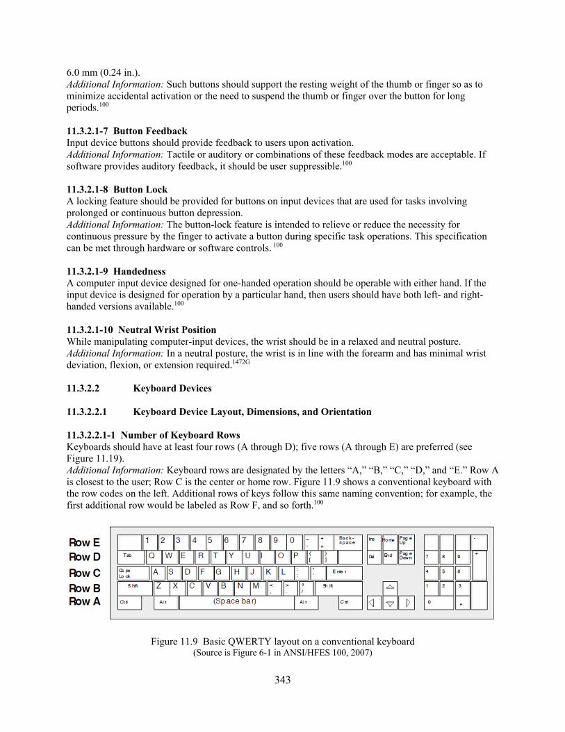
343
6.0 mm (0.24 in.). Additional Information: Such buttons should support the resting weight of the thumb or finger so as to minimize accidental activation or the need to suspend the thumb or finger over the button for long periods.100 11.3.2.1-7 Button Feedback Input device buttons should provide feedback to users upon activation. Additional Information: Tactile or auditory or combinations of these feedback modes are acceptable. If software provides auditory feedback, it should be user suppressible.100 11.3.2.1-8 Button Lock A locking feature should be provided for buttons on input devices that are used for tasks involving prolonged or continuous button depression. Additional Information: The button-lock feature is intended to relieve or reduce the necessity for continuous pressure by the finger to activate a button during specific task operations. This specification can be met through hardware or software controls. 100 11.3.2.1-9 Handedness A computer input device designed for one-handed operation should be operable with either hand. If the input device is designed for operation by a particular hand, then users should have both left- and right-handed versions available.100 11.3.2.1-10 Neutral Wrist Position While manipulating computer-input devices, the wrist should be in a relaxed and neutral posture. Additional Information: In a neutral posture, the wrist is in line with the forearm and has minimal wrist deviation, flexion, or extension required.1472G 11.3.2.2 Keyboard Devices 11.3.2.2.1 Keyboard Device Layout, Dimensions, and Orientation 11.3.2.2.1-1 Number of Keyboard Rows Keyboards should have at least four rows (A through D); five rows (A through E) are preferred (see Figure 11.19). Additional Information: Keyboard rows are designated by the letters “A,” “B,” “C,” “D,” and “E.” Row A is closest to the user; Row C is the center or home row. Figure 11.9 shows a conventional keyboard with the row codes on the left. Additional rows of keys follow this same naming convention; for example, the first additional row would be labeled as Row F, and so forth.100
Figure 11.9 Basic QWERTY layout on a conventional keyboard (Source is Figure 6-1 in ANSI/HFES 100, 2007)

344
11.3.2.2.1-2 Typing Keyboard Layout The typing keyboard should use an ANSI standard (QWERTY) layout. Additional Information: Common usage and the ability to transfer from one keyboard to another have led to the general acceptance of the QWERTY keyboard. Figure 11.9 illustrates this key arrangement. 5908 11.3.2.2.1-3 Numeric Keypad When users must enter numeric data, keyboards should be equipped with a numeric keypad. 5908 11.3.2.2.1-4 Numeric Keypad Layout Keypads used for numeric entry should be consistently designed with a conventional layout. Additional Information: Keypad layout should be one of the two illustrated in Figure 11.10. 5908 They are known as the telephone and calculator layouts.100
Figure 11.10 Two numeric keypad layouts (Source is Figure 6-2 in ANSI/HFES 100, 2007)
11.3.2.2.1-5 Cursor Control Keys Horizontal and vertical cursor control keys should be provided for text processing applications. Additional Information: Ideally, keys for cursor control should allow (1) horizontal and vertical movement, (2) movement along the diagonals, and (3) two or more rates of movement that are user selectable. Cursor keys should be dedicated to cursor movement; that is, they should not be used for any function but cursor control. If, however, the cursor keys are not dedicated (i.e., they have collateral functions), their functional status should be clearly indicated. 5908 11.3.2.2.1-6 Cursor Key Layout Cursor control keys should be arranged in a two-dimensional layout so that their orientation is compatible with the cursor motion they produce. Additional Information: Cursor keys may be arranged in a “cross” or “inverted-T” format. Figure 11.11 illustrates examples of such key arrangements. 5908, 100
Figure 11.11 Four cursor control key layouts (Source is Figure 6-3 in ANSI/HFES 100, 2007)
345
11.3.2.2.1-7 Editing Keys Editing keys (insert, delete, home, end, page up, page down) should be provided for keyboard navigation, control, and editing tasks. Additional Information: These keys should be arranged in a functional group.100 11.3.2.2.1-8 Dual-State Keys Dual-state (toggle) keys should indicate their operational (functional) status. Additional information: Dual-state keys include keys such as Caps Lock, Num Lock, Scroll Lock, and Function Lock. A common problem with dual-state keys or pushbuttons is visual identification of the position or state of the key. The preferred solution is to provide a separate indicator light for the status of each such dual-state key. When indicator lights are employed, they should be imbedded in the key, located close to the associated key, or be clearly labeled if not located close to the keys (e.g., Caps Lock icon). An indicator panel for one or more dual-state keys is also acceptable. Other means for indicating the status of dual-state keys may be showing the functional status on the receiver of a wireless keyboard or on the primary or main display.100 11.3.2.2.1-9 Key Row Contour For standard keyboard designs, the keyboard rows should be arranged in a dished (concave), stepped, sloped, or flat profile. Additional Information: Some special keyboard designs may use height, articulation, and tilt advantageously to aid in promoting neutral wrist posture. 100 11.3.2.2.1-10 Overlays Mechanical overlays, such as coverings over the keyboard, should not be used. 5908 11.3.2.2.1-11 Keyboard Thickness (Height) The thickness of the keyboard should be a maximum of 35 mm (1.37 in.) to a maximum of 30 mm (1.18 in.). Additional Information: The thickness of the keyboard is the height from the base to the home row of keys (Row “C” in Figure 11.19). 100 11.3.2.2.1-12 Keyboard Slope Adjustment The user should be able to adjust the slope of the keyboard. Additional Information: Keyboards should be capable of being positioned in slopes covering the range between a minimum of 0 degrees and a maximum of 15 degrees relative to the horizontal. At least one keyboard slope should be in this range. Certain contemporary or alternative keyboard designs may have a positive slope greater than 15 degrees, or may even have a negative slope, so long as the overall design promotes a neutral wrist posture in all intended users.100, 5908 11.3.2.2.1-13 Standard Keyboard Placement The user should be able to reposition the standard keyboard on the work surface. 5908 11.3.2.2.1-14 Inadvertent Operation Keys with major or destructive effects should be located so that inadvertent operation is unlikely. 5908 11.3.2.2.1-15 Multiple Keyboards Control rooms that include more than one keyboard should maintain the same configuration for alphanumeric, numeric, and special function keys throughout the control room, as well as across other computer systems the user is expected to operate.1472G
346
11.3.2.2.1-16 Alternate Key Definitions When the keyboard is redefined, a display of the alternate characters and their locations should be available to the user. 5908 11.3.2.2.1-17 Home Row Locator The home row keys (Row “C” in Figure 11.19) should contain at least one tactile feature to assist users in positioning their fingers on the keyboard. Additional Information: Current industry practice is to use a small raised bar, a dimple, or some other shape on the key cap. A tactile indicator on the home row keys, typically the “F” and “J” keys in the alphanumeric area and the “5” key on the numeric keypad, provides a reference landmark for users to orient their hands and fingers on the keyboard.100 11.3.2.2.1-18 Attached Keyboard Wrist Rest For keyboards with integrated or attachable wrist rests or palm supports for maintaining the proximal portion of the palm, the rest or supports should be matched to the width, height, and shape of the front edge and slope of the keyboard. Additional Information: Section 11.3.5.4, “Wrist/Palm/Forearm Supports,” covers separate detached wrist rests.100 11.3.2.2.2 Data Entry Key Characteristics 11.3.2.2.2-1 Keytop Size The width of the horizontal strike surface of the keytop should be a minimum of 12 mm (0.47 in.), preferably 18 mm (0.7 in.) for use with gloves. Additional Information: Rectangular or square keys are preferred. 5908, 1472G 11.3.2.2.2-2 Keytop Contour The keytop contact surface should be concave to match the geometry of the tip of the finger. Additional Information: Concave keys provide a good fit to fingertips and enhance coupling during the striking action of the fingers.100 11.3.2.2.2-3 Key Symbols The letters, numbers, and other symbols on the keyboard should have clearly legible symbols on the keys indicating what each key is for.100 11.3.2.2.2-4 Key Symbol Height The height of the primary symbols on the keys should be a minimum of 2.5 mm (0.1 in.). 5908 11.3.2.2.2-5 Key Symbol Contrast The primary symbols on the keys should be colored with high contrast lettering. The contrast ratio between the lettering and the key background should be a minimum of 3:1. Additional Information: Symbols on keys may be darker or lighter than the background. 5908 11.3.2.2.2-6 Key Symbol Marking Key symbols should be etched (to resist wear) and colored with high-contrast lettering. 5908 11.3.2.2.2-7 Key Symbol Font Keys should be labeled with a nonstylized font. 5908 11.3.2.2.2-8 Key Spacing Center line distances between adjacent keys should be in the range between a minimum of 18 mm

347
(0.71 in.) and a maximum of 19 mm (0.75 in.) horizontally and between 18 mm (0.71 in.) and 21 mm (0.82 in.) vertically. Additional Information: The above key-spacing specification applies to keys within a functional group but not to the separation between functional groups of keys. Key spacing is measured by the horizontal or vertical distance between corresponding points on two adjacent keys. Function keys and infrequently used keys may have a smaller key spacing. 5908, 100 11.3.2.2.2-9 Key Height Key height for alphanumeric keyboards should be in the range between a minimum of 10 mm (0.35 in.) and a maximum of 13 mm (0.5 in.). 5908 11.3.2.2.2-10 Key Activation Force The force required to depress keys to the snap point should be in the range between a minimum of 0.25 N (0.9 ounces) and a maximum of 1.5 N (5.4 ounces); the preferred key force is in the range between 0.5 N (1.8 ounces) and 0.6 N (2.2 ounces). Additional Information: For repetitive keying tasks, the force required for key displacement should be in the range between a minimum of 0.3 N (1.1 ounces) and a maximum of 0.75 N (2.7 ounces). Variability of the key-activation force among different alphanumeric keys should be minimized. Static force measurements should be made at the center of the keys and at the corners. When measured at the corners, there should be minimal binding (actuating force increase) at the corner locations.100, 5908 11.3.2.2.2-11 Key Displacement The vertical displacement of the alphanumeric keys should be in the range between a minimum of 1.5 mm (0.05 in.) and a maximum of 6.0 mm (0.25 in.); the preferred displacement is in the range between 2.0 mm (0.1 in.) and 4.0 mm (0.15 in.). Additional Information: Displacement variability between keys should be minimized. 5908 11.3.2.2.2-12 Keying Feedback The actuation of a key should be accompanied by tactile or auditory feedback or both. Additional Information: If there is only one type of feedback, tactile feedback is preferred. Should supplementary auditory feedback be used, the sound should occur at the same point in the displacement for all keys. Supplementary auditory feedback should be adjustable in volume and capable of being turned off. 5908 11.3.2.2.2-13 Repeat Capability A repeat capability for alphanumeric, symbol character, and cursor keys should be provided. Additional Information: The repeat function should have a user-selectable delay with a default of 0.5 second. In addition, the character should be repeated at a user-selectable rate with a default of 10 characters per second. The physical release of the key should terminate the repeat. 5908 11.3.2.2.2-14 Rapid Keystrokes Rapid bursts of keystrokes should not result in characters being lost or transmitted out of sequence. Additional Information: Multiple-key rollover capability reduces input errors by preserving the order in which keys are struck regardless of keys being depressed at the same time. Keyboards should have at least a three-key rollover. An n-key rollover is recommended.100, 5908
11.3.2.2.2-15 Keystroke Commands When it is necessary to distinguish command entries from text input, a specially designated key should be used for keystroke commands. 5908

348
11.3.2.2.2-16 Simultaneous Keystrokes Commands executed by chord-keying should require the user to press the keys simultaneously, not in close temporal sequence. Additional Information: Requiring the user to press two keys simultaneously reduces the likelihood of inadvertent input of a command caused by a missed keystroke that hits the specially designated key, followed immediately by another keystroke. 5908 11.3.2.2.3 Function Keys 11.3.2.2.3-1 Availability Fixed function keys should be continuously available to control functions that are often used. Additional Information: Lockout of fixed function keys should be minimized. 5908 11.3.2.2.3-2 Inactive Function Keys Unneeded function keys, either fixed or programmable, should be disabled so that no other action occurs upon their depression except an advisory message. Additional Information: At any step in a transaction sequence, function keys that are not used for current inputs should be temporarily disabled under computer control. Mechanical overlays should not be used for this purpose. 5908 11.3.2.2.3-3 Inactive Keys Nonactive fixed function keys should not be present on the keyboard. Additional Information: The presence of nonrelevant keys, such as those used by programmers, adds to keyboard complexity and induces user errors. Control room keyboards should contain only those keys used by control room personnel. 5908 11.3.2.2.3-4 Grouping Fixed function keys should be logically grouped and placed in distinctive locations on the keyboard. Additional Information: Color coding can be used to highlight functional key groups. When this is done, the color of alphanumeric keys should be neutral (e.g., beige, gray, or black). 5908 11.3.2.2.3-5 Function Labels Key assignments should be displayed at all times, preferably through direct marking. Additional Information: Where abbreviations are necessary, they should be standardized. 5908 11.3.2.2.3-6 Consistency Fixed function keys should be used consistently on all keyboards throughout the system. 5908 11.3.2.2.3-7 Actuation Fixed function keys should require only a single actuation to accomplish their function.5908 11.3.2.2.3-8 Repeat for Special Functions Function keys (except for the delete key) should not repeat upon prolonged depression.5908 11.3.2.2.3-9 Status Display When the effect of a function key varies, the status of the key should be displayed. Additional Information: Variable function keys should be easily relabeled.5908 11.3.2.2.3-10 Easy Return to Initial Functions Where the functions assigned to a set of function keys change because of user selection, the user should be given an easy means to return to the initial functions.5908

349
11.3.2.2.3-11 Reprogrammable or Inactive Default Functions When keys with labeled default functions are reprogrammed or turned off, a visual indication should alert the user that the standard function is not currently accessible by that key.5908 11.3.2.2.3-12 Shifted Characters Shift keys should not be required to operate variable function keys.5908 11.3.2.3 Pointer or Controller Input Devices 11.3.2.3.1 General Pointer or Controller Input Device Characteristics 11.3.2.3.1-1 Appropriate Pointer or Controller Input Device for the Task The type of pointer or controller input device should be appropriate for the tasks anticipated for its use. Additional Information: Table 11-6 identifies the appropriate use of various control and input devices. ISO Standard 9241-9, “Requirements for Non-keyboard Input Devices,” provides guidance on how to measure the effectiveness and usability of nonkeyboard computer input devices.5908
Table 11.6 Control and input devices for human-computer interaction
Device Conditions for Appropriate Use Cursor Control Keys Cursor moves in X and Y dimensions. Touch Screen Moving/holding arm to screen for long periods of time is not required.
Screen does not have small poke points relative to size of fingertip. A low level of resolution is required for positioning. Task will not be disrupted by hand temporarily blocking screen.
Light Pen High positioning precision is not required. Holding arm to screen for long periods of time is not required.
Mouse Adequate space is available for mouse movement over a pad or desktop. A low-to-medium level of resolution is required for positioning. Periodic cleaning is provided.
Isotonic Joystick (Displacement)
Positioning accuracy is more important that positioning speed.
Trackball
Rapid cursor positioning is desirable. Limited space is available for installing an input device.
Graphics Tablet A low-to-medium level of resolution is required. Isometric Joystick (Force)
Precise or continuous control of two or more related dimensions is required.
11.3.2.3.1-2 Dynamic Characteristics The pointer or controller input device should be able to produce any combination of x-and y-axis output values. While manipulating the control, neither backlash nor cross-coupling should be apparent to the user. Additional Information: The follower (cursor) manipulated by the controller should smoothly track the movement of the controller in the same direction, within +/- 10 degrees, without backlash, cross-coupling, or the need for multiple corrective movements. 5908 11.3.2.3.1-3 Control Dynamics Expectations The control dynamics, such as control/display ratio, should be compatible with users’ expectations for

350
direction, speed, and location of movement.100
11.3.2.3.1-4 Selectable Tracking Speed The user should be able to select the pointer or controller tracking speed (control-display ratio) from a predefined range; the default speed should be moderate. Additional Information: Control ratios and dynamic features should meet the dual requirement of rapid gross positioning and smooth, precise fine positioning. The control/display ratios should consider both screen size and maximum maneuvering displacement. At a minimum, movement of the controller across the entire maneuvering surface should move the cursor from one side of the screen to the other. 5908 11.3.2.3.1-5 Intentional Movements There should be a balance between the effort and force required for the user to position the device easily and the need for the device to remain stable at its intended position. Additional Information: Users should be able to position input devices accurately and quickly without exerting excessive effort or force. However, the effort or force required to position the input device should be sufficient to prevent the device from unintended drifting or changing of position.100 11.3.2.3.1-6 Grip Surface The grip surfaces should be sized, shaped, and textured to prevent slipping and unintended movements during normal operation. 100 11.3.2.3.1-7 Grip Constancy Input devices with buttons should permit button activation without requiring alteration of the handgrip. 100 11.3.2.3.1-8 Selectable Interclick Interval If multiple clicks are required on a selection button, the user should be able to select the interclick interval from a predefined range; the default interval should be moderate. 5908 11.3.2.3.1-9 Single Monitor and Single Controller Cursor Travel Limits In a single monitor and single controller workstation, movement of the controller should drive the follower to the edge of the screen only and not off the screen. 5908 11.3.2.3.1-10 Separation of Selectable Screen Items Selectable screen items or regions should be separated from each other by a sufficient distance to minimize inadvertent activation of adjacent items or regions. 5908 11.3.2.3.2 Mouse Devices 11.3.2.3.2-1 Appropriate Use A mouse device should not be used to generate precise free-drawn graphics.1472G 11.3.2.3.2-2 Mouse Shape The mouse device should have no sharp edges and should be shaped roughly as a rectangular solid. 5908 11.3.2.3.2-3 Mouse Size The mouse should be of a size that can be comfortably gripped in a single hand by the user. Additional Information: For a comfortable grip, the width of a rectangular-shaped mouse should be in the range between a minimum of 40 mm (1.6 in.) and a maximum of 70 mm (2.8 in.), the length between 70 mm (2.8 in.) and 120 mm (4.7 in.), and the height between 25 mm (1.0 in.) and 40 mm (1.6 in.).100

351
11.3.2.3.2-4 Mouse Sensor Position The motion sensor on the mouse should be located toward the front of the input device, under the fingertips, not under the palm.100 11.3.2.3.2-5 Limb Support When a mouse is used to make precise or continuous adjustments, hand, wrist, or arm supports should be provided. 5908 11.3.2.3.2-6 Connection If the mouse is connected to the computer by a cable, the cable should be long enough to remain slack during use.1472G 11.3.2.3.3 Trackball Devices 11.3.2.3.3-1 Trackball Geometry The diameter of the rotating portion of a desktop-mounted trackball device should be in the range between a minimum of 50 mm (2.0 in.) and a maximum of 150 mm (5.9 in.), and the exposed surface of the rotating portion of the trackball should be between 100 and 140 degrees.100 11.3.2.3.3-2 Trackball Resistance The resistance force of the trackball rotating sphere should be a minimum of 1.0 N (0.22 pounds), and preferably 0.3 N (0.66 pounds).100 11.3.2.3.3-3 Limb Support When trackballs are used to make precise or continuous adjustments, hand, wrist, or arm supports should be provided. 5908 11.3.2.3.4 Joystick Devices 11.3.2.3.4-1 Appropriate Use of Displacement (Isotonic) Joysticks Displacement joysticks are preferred over force joysticks when positioning accuracy is more critical than positioning speed. Additional Information: Displacement joysticks that are used for rate control should be spring-loaded for return to center when the hand is removed. Displacement joysticks usually require less force than force joysticks and are less fatiguing for long operating periods. Hand-operated displacement joysticks may be used as mounting platforms for secondary controls, such as thumb and finger-operated switches. Operation of secondary controls is less error prone with displacement (isotonic) handgrips than with force (isometric) handgrips. 5908 11.3.2.3.4-2 Appropriate Use of Force (Isometric) Joysticks Force joysticks are preferred over displacement joysticks when precise or continuous control in two or more related dimensions is required. Additional Information: Force joysticks are particularly appropriate for applications: (1) that require precise return to center after each use, (2) in which feedback is primarily visual rather than tactile feedback from the control itself, and (3) where there is minimal delay and tight coupling between control and input and system reaction. When positioning speed is more critical than positioning accuracy, force joysticks should be selected over displacement joysticks. 5908 11.3.2.3.4-3 Force Joystick Dynamic Characteristics The output of the force joystick should be proportional to and in the same direction as the user’s perceived applied force. The force to displace the cursor with a hand- or finger-operated joystick should

352
be a minimum of 4.5 N (1.0 pound). The force for full output should be a maximum of 118 N (27 pounds). Additional Information: Movement should be smooth in all directions, and positioning of a follower should be attainable without noticeable backlash, cross-coupling, or the need for multiple corrective movements. Control ratios, friction, and inertia should meet the dual requirements of rapid gross positioning and precise fine position. When used to generate free-drawn graphics, the refresher rate for the follower on the display should be sufficiently high to give the appearance of a continuous track. 100, 5908 11.3.2.3.4-4 Displacement Joystick Dynamic Characteristics The output of the displacement joystick should be proportional to and in the same direction as the displacement of the joystick from the center. The maximum joystick movement should be 45 degrees from the center position. Additional Information: The resistance should be sufficient to maintain the handle position when the hand is removed. Movement should be smooth in all directions, and positioning of a follower should be attainable without noticeable backlash, cross-coupling, or the need for multiple corrective movements. Control ratios, friction, and inertia should meet the dual requirements of rapid gross positioning and precise fine positioning. When used to generate free-drawn graphics, the refresh rate for the follower on the display should be sufficiently high to give the appearance of a continuous track. 5908 11.3.2.3.4-5 Hand-Operated Joystick Dimensions and Clearances For a hand-operated joystick, the handgrip length should be in the range between a minimum of 110 mm (4.3 in.) and a maximum of 180 mm (7 in.). The grip diameter should be a maximum of 50 mm (2 in.). To allow for hand movement, joystick clearances should be a minimum of 100 mm (4 in.) to the side and 50 mm (2 in.) to the rear. 5908 11.3.2.3.4-6 Finger-Operated Joystick Dimensions The handle of a finger-operated joystick should have a diameter in the range between a minimum of 6.5 mm (0.26 in.) and a maximum of 16.0 mm (0.63 in.), and should have a length between 25 mm (1.0 in.) and 150 mm (5.9 in.).100 11.3.2.3.4-7 Positive Centering Joysticks should have the capability for an automatic return to the “home position.”5908 11.3.2.3.4-8 Limb Support Joysticks should be mounted to provide forearm or wrist support.1472G 11.3.2.3.5 Light Pen, Stylus, and Graphic Tablet Devices 11.3.2.3.5-1 Appropriate Use of a Light Pen A light pen may be used for noncritical input when precise positioning is not required; it should not be used when the task would require holding the pen up to the screen for long periods of time. Additional Information: Tasks involving light pens should not require frequent, alternating use of the light pen and the keyboard. 5908 11.3.2.3.5-2 Appropriate Use of a Stylus or Graphics Tablet Grid and stylus devices may be used for picking data from a display and entering points on a display. Additional Information: Displacement of the stylus from the reference position should cause a proportional displacement of the follower. The grid may be on a transparent medium allowing stylus placement directly over corresponding points on the display, or it may be displaced from the display in a convenient position for stylus manipulation. In either case, a follower should be presented on the display

353
at the coordinate values selected by the stylus. 5908 11.3.2.3.5-3 Activation Light pens and graphics tablets should be equipped with an activation/deactivation mechanism. Additional Information: This feature is to prevent inadvertent actuation. For most light pen applications, a pushtip switch is preferred. This switch should have an actuation force in the range between a minimum of 0.5 N (2 ounces) and a maximum of 1.4 N (5 ounces). 5908 11.3.2.3.5-4 Feedback Two forms of feedback should be provided: (1) feedback concerning the position of the follower, and (2) feedback that the pointing device has actuated and the input has been received by the system. Additional Information: Feedback can be in the form of displayed follower (such as a circle or crosshair) or highlighting. 5908 11.3.2.3.5-5 Dynamic Characteristics When used as a two-axis controller, movement of the pointing device in any direction on the surface of the screen or tablet should result in smooth movement of the follower in the same direction. Additional Information: Discrete placement of the pointing device at any point on the surface should cause the follower to appear at the corresponding coordinates and to remain steady so long as the light pen is not moved. The refresh rate for the follower should be sufficiently high to ensure the appearance of a continuous track. 5908 11.3.2.3.5-6 Follower Visibility For touch screens and light pens, the follower should be visible on the screen while the pointing device is touching the screen. 5908 11.3.2.3.5-7 Serial Command Response The system should accept only one command at a time. 5908 11.3.2.3.5-8 Feedback for Multiple Devices Distinguishable audible beeps (used to supply feedback) should be used when more than one touch screen, light pen, or graphics tablet is employed. 5908 11.3.2.3.5-9 Light Pen and Input Stylus Dimensions The light pen or input stylus length should be in the range between a minimum of 120 mm (4.75 in.) and a maximum of 180 mm (7 in.), with a diameter of between 7 mm (0.3 in.) and 20 mm (0.75 in.). 5908 11.3.2.3.5-10 Light Pen and Input Stylus Characteristics The light pen or input stylus device should do the following: a. have an exterior surface that should not allow the pen or stylus to slip from the user’s hand b. be comfortable to hold and easy to grip c. have barrel-mounted buttons that are shaped for comfort and to minimize sharp edges and
pressure points d. have a conveniently located clip to hold the device when not in use 100, 5908

354
11.3.2.3.5-11 Graphic Tablet Size and Orientation Transparent grids that are used as display overlays should conform to the size of the display. Grids that are displaced from the display should approximate the display size and should be mounted below the display in an orientation to preserve directional relationships to the maximum extent. Additional Information: For example, a vertical plane passing through the north/south axis on the grid should pass through or be parallel to the north/south axis on the display. 5908 11.3.2.3.5-12 Tablet and Overlay Surface The active area of a tablet or touch-sensitive surface should be flat, smooth, and free from warping or surface imperfections.100 11.3.2.3.6 Touch-Screen Devices 11.3.2.3.6-1 Appropriate Use of Touch-Screen Devices Touch screens are appropriate for tasks involving the occasional selection of objects on position displays, layout diagrams, piping diagrams, discrete-function controls, or opening and closing valves. Additional Information: Touch-screen devices are not recommended if the task requires holding the arm up to the screen for long periods of time or the entry of large amounts of data. Also, they should not be used for tasks that require frequent, alternating use of the touch screen and a keyboard, or long-term continuous data entry. Table 11.7 gives the advantages and disadvantages of touch screens.1472G, 5908
Table 11.7 Advantages and disadvantages of touch-screen use
Advantages Disadvantages No separate input device Slower alphanumeric data entry Programmable interface Arm fatigue Fast access Finger may obstruct view Direct manipulation of targets Fingerprints or other debris may obscure screen Input/output in same location Large buttons required for finger use Intuitive Pointing is not very accurate Natural pointing action User must be within reach of screen Generally, no additional desk space required1 No tactile feedback provided3 Generally, no training required2 Unable to rest finger on target without actuation3
Gloved operation may be incompatible with some touch technology Controls must be deactivated for cleaning
1. If incorporation is part of an existing primary display. 2. Application dependent. 3. If a tactile membrane is not incorporated. Note: Source is Table VI in MIL-STD-1472G (DoD, 2012). 11.3.2.3.6-2 Dimensions and Separation of Touch Zones To allow for finger size and parallax inaccuracy, for large and medium screen sizes, the dimensions of response areas on touch screens should be in the range between a minimum height and width of 10 mm (0.4 in.) and a maximum height and width of 40 mm (1.5 in.), with a separation distance of between 3 mm (0.1 in.) and 6 mm (0.25 in.). Additional Information: The optimum touch-sensitive area depends on the application and required accuracy. Touch areas greater than 22 mm (0.9 in.) square do not tend to improve performance. 5908,100 11.3.2.3.6-3 Touch-Screen Resistance The force required to operate force-actuated touch screens should be in the range between a minimum of s

355
0.25 N (0.9 ounce) and a maximum of 1.5 N (5.3 ounces). Additional Information: Touch screen force sensitivity should match all operational modes, including gloved operations during an emergency. 5908, 1472G 11.3.2.3.6-4 Neutral Tint of Touch Overlays Touch-screen overlays should have a neutral tint that does not distort colors or interfere with color coding. 5908 11.3.2.3.6-5 Target Tracking During a select-and-drag operation on a touch screen, the object or cursor being moved should track the finger, both temporally and spatially.100 11.3.2.3.6-6 Positive Indication A positive indication of touch-screen actuation should be provided to acknowledge the system response to the control action. 1472G 11.3.2.3.6-7 Display Response Time (Latency) Display response time should be a maximum of 100 ms, preferably 55 ms.1472G 11.3.2.3.6-8 Important Tasks Where a touch-screen control is used for an important task, the system response should require an additional, confirmatory action to ensure that the control actuation is intended. Where confirmatory action is impractical, multiple touch actuations should be employed. 1472G 11.3.2.3.6-9 Repeat Function Delay When a repeat delay function is employed, the initial delay should be in the range between a minimum of 500 ms to a maximum of 750 ms. All repeat functions should display the fact that a repeat request has been initiated.1472G 11.3.2.3.6-10 Reach Considerations Touch screen devices should be located to do the following: a. ensure users can reach and actuate all areas of the screen, including the corners of the display b. avoid full arm extension c. avoid upward reach 1472G
11.3.2.3.6-11 Elbow Support Elbow support should be provided where possible to minimize arm fatigue.1472G 11.3.3 Hand-Held Devices 11.3.3-1 Usability Hand-held visual display devices used at the workstation should be designed so that they may be viewed, read, and manipulated to the required degree of accuracy. 1472G 11.3.3-2 Display Image Conversion When converting a display image from the traditional workstation sizes to a hand-held device, the new design should adapt, and not necessarily simply copy, the design used on the traditional system. Additional Information: Legacy software systems designed for use with larger displays should be
356
modified where required to ensure that information is sufficiently visible and legible on smaller hand-held devices. 1472G 11.3.3-3 Access to Important Information When designing hand-held display image navigation, important information should be reachable in less than three key actions (e.g., scrolling and tapping). 1472G 11.3.3-4 Navigating Long Pages When text passages are longer than can be displayed on one screen image, subtitles, hypertext, and scrolling markers should be used to assist the user. 1472G 11.3.3-5 Text Organization The display design, fonts, and text organization should be modified to perform effectively on a very small screen.1472G
11.3.3-6 User Input Mode Direct input pointers (e.g., touch screen, light pen) should be used rather than indirect input pointers (e.g., trackball, mouse). 1472G
11.3.4 Desktops and Work Surfaces 11.3.4.1 General Configuration 11.3.4.1-1 Stand-Only Work Surface Height For a stand-only workstation, the work surface height (measured from the top of the work surface) should be in the range between a minimum of 90 cm (35.4 in.) and a maximum of 93 cm (36.6 in.) above the floor surface. If the work surface is being used for locating certain types of controls (joystick, track ball, and keyboards), and the work surface is not adjustable in height, the work surface height should be in the range between 102 cm (40.1 in.) and 107 cm (42.1 in.) above the floor surface.1472G 11.3.4.1-2 Sit-Only Work Surface Height For a sit-only workstation, the work surface height (measured from the top of the work surface) should be in the range between a minimum of 66 cm (26 in.) and a maximum of 78.7 cm (31 in.) above the floor surface. The recommended sit-only work surface height is in the range between 73.7 cm (29 in.) and 76.2 cm (30 in.) above the floor surface.0700, 1472G 11.3.4.1-3 Sit-Stand Work Surface Height For a sit-stand workstation, the work surface height (measured from the top of the work surface) should be in the range between a minimum of 91.4 cm (36 in.) and a maximum of 96.5 cm (38 in.) above the floor surface.0700 11.3.4.1-4 Work Surface Width The work surface width should be a minimum of 76 cm (30 in.) measured along the top of the work surface. 0700 11.3.4.1-5 Work Surface Depth The work surface depth should be a minimum of 41 cm (16 in.) measured along the top of the work surface.0700 11.3.4.1-6 Work Surface Depth Allowances The work surface depth should allow the following:
357
a. positioning the visual display for a minimum viewing distance of 50 cm (19.7 in.) b. positioning the visual display so that the angle between the horizontal level of the eyes
and the center of the screen is in the range between a minimum of minus 15 degrees and a maximum of minus 25 degrees
c. positioning the entire user viewing area (e.g., including the keyboard) in an arc 60 degrees below
the horizontal eye level 100 11.3.4.1-7 Work Surface Stability The work surface should be rigid and stable for all expected working conditions. Additional Information: The rigidity, stability, and durability of work surfaces should conform to ANSI/Business and Institutional Furniture Manufacturers Association (BIFMA x5.5-2014 on Desk/Table Products—Tests. 100 11.3.4.2 Clearance Under Work Surfaces 11.3.4.2-1 Leg and Foot Room Sufficient leg and foot room should be provided to enable seated users to avoid awkward and uncomfortable positions. Additional Information: Leg and foot room clearances under the work surface should apply to all types of work surfaces, including the primary work surface, visual display device support surface, and input device support surface. 0700, 100
11.3.4.2-2 Leg/Foot Position Leg room clearances under the work surface should accommodate a 120-degree knee bend and a 10-degree ankle bend.14 11064-4 11.3.4.2-3 Front-Edge Leg Room Height Along the front edge of the work surface, the leg room clearance height (measured from the bottom of the work surface) should be in the range between a minimum of 50 cm (19.7 in.) and a maximum of 72 cm (28.3 in.) above the floor surface. If the reclining and relaxed seated work postures are not supported, this maximum value may be reduced to 69 cm (27.2 in.) above the floor surface.100 11.3.4.2-4 Knee-Position Leg Room Height At the horizontal position of the knee, the leg room clearance height (measured from the bottom of the work surface) should be adjustable to cover the range between a minimum of 50 cm (19.7 in.) and a maximum of 64 cm (25.2 in.) above the floor surface.100 11.3.4.2-5 Leg Room Clearance Width The leg room clearance width should be a minimum of 52 cm (20.5 in.). 100 11.3.4.2-6 Knee-Level Leg Room Depth The leg room clearance depth should be a minimum of 50 cm (19.7 in.) measured at the level of the knee.100
14 © ISO. This material is excerpted from ISO 11064-4: 2004 with the permission of ANSI on behalf of ISO. All rights
reserved.

358
11.3.4.2-7 Foot-Level Leg Room Depth The leg room clearance depth should be a minimum of 60 cm (23.6 in.) measured at the level of the foot.100
11.3.4.2-8 Under-Surface Angle for Leg Room Clearance Because of the differing leg room height clearances at the front edge of the work surface and at the horizontal knee position of the user, the under surface of the leg room clearance envelope may be tilted at an angle.100 11.3.4.2-9 Foot Clearance A foot clearance of 10.2 cm (4 in.) vertically and in depth is recommended. Additional Information: Enough foot room should be provided to allow the user to get close to the workstation without leaning.0700 11.3.5 Workstation Support Devices 11.3.5.1 Visual Display Support Surface/Device 11.3.5.1-1 Adjustment of Viewing Distance The visual display support surface/device should allow the user to adjust the LOS (viewing) distance between the eye point of the user and the front surface of the visual display screen viewing area. This viewing distance adjustment should cover the range between a minimum of 50 cm (19.7 in.) and a maximum of 100 cm (39.4 in.).100 11.3.5.1-2 Adjustment of Tilt and Rotation Angle The visual display support surface/device should allow the user to adjust the tilt and rotation angle between the eye point of the user and the front surface of the visual display screen viewing area.100 11.3.5.1-3 Visual Display Adjustment Clearance The visual display support surface/device should not interfere with the ability of the user to adjust the height, tilt and rotation of the visual display.100 11.3.5.1-4 Visual Display Stability The visual display support surface/device should be stable during use.100 11.3.5.2 Input Device Support Surface 11.3.5.2-1 Input Device Forward and Backward Adjustability The input device support surface should adjust forward and backward in the horizontal plane. Additional Information: Input device support surfaces include adjustable keyboard and adjustable mouse pad support surfaces or trays. 100
11.3.5.2-2 Input Device Side-to-Side Adjustability The input device support surface should adjust in side-to-side placement within the optimal area for input devices.100 11.3.5.2-3 Input Device Surface Height The input device surface height should be adjustable (see Table 11.8). 100
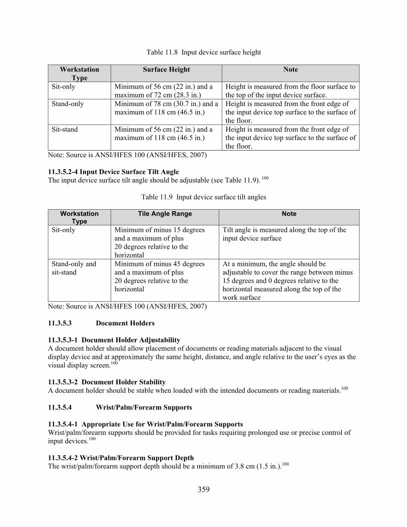
359
Table 11.8 Input device surface height
Workstation Type
Surface Height Note
Sit-only Minimum of 56 cm (22 in.) and a maximum of 72 cm (28.3 in.)
Height is measured from the floor surface to the top of the input device surface.
Stand-only Minimum of 78 cm (30.7 in.) and a maximum of 118 cm (46.5 in.)
Height is measured from the front edge of the input device top surface to the surface of the floor.
Sit-stand Minimum of 56 cm (22 in.) and a maximum of 118 cm (46.5 in.)
Height is measured from the front edge of the input device top surface to the surface of the floor.
Note: Source is ANSI/HFES 100 (ANSI/HFES, 2007) 11.3.5.2-4 Input Device Surface Tilt Angle The input device surface tilt angle should be adjustable (see Table 11.9). 100
Table 11.9 Input device surface tilt angles
Workstation Type
Tile Angle Range Note
Sit-only Minimum of minus 15 degrees and a maximum of plus 20 degrees relative to the horizontal
Tilt angle is measured along the top of the input device surface
Stand-only and sit-stand
Minimum of minus 45 degrees and a maximum of plus 20 degrees relative to the horizontal
At a minimum, the angle should be adjustable to cover the range between minus 15 degrees and 0 degrees relative to the horizontal measured along the top of the work surface
Note: Source is ANSI/HFES 100 (ANSI/HFES, 2007) 11.3.5.3 Document Holders 11.3.5.3-1 Document Holder Adjustability A document holder should allow placement of documents or reading materials adjacent to the visual display device and at approximately the same height, distance, and angle relative to the user’s eyes as the visual display screen.100 11.3.5.3-2 Document Holder Stability A document holder should be stable when loaded with the intended documents or reading materials.100 11.3.5.4 Wrist/Palm/Forearm Supports 11.3.5.4-1 Appropriate Use for Wrist/Palm/Forearm Supports Wrist/palm/forearm supports should be provided for tasks requiring prolonged use or precise control of input devices.100 11.3.5.4-2 Wrist/Palm/Forearm Support Depth The wrist/palm/forearm support depth should be a minimum of 3.8 cm (1.5 in.).100

360
11.3.5.4-3 Wrist/Palm Support Width The wrist/palm support width should be a minimum of 3.8 cm (1.5 in.).100 11.3.5.4-4 Wrist/Palm/Forearm Support Adjustability The wrist/palm/forearm support should be adjustable in height, tilt, and position.100 11.3.5.4-5 Wrist/Palm/Forearm Support Configuration/Material Wrist/palm/forearm supports should have the necessary shape and firmness to do the following: a. attain the proper user forearm/wrist/hand posture b. distribute forces evenly over the contact area c. maintain a comfortable thermal balance d. avoid excessive pressure points e. avoid being so soft as to limit hand movement f. avoid irritating or abrading the skin 100 11.4 Workstation Labeling and Demarcations 11.4.1 Labels 11.4.1.1 Labeling Principles 11.4.1.1-1 Need for Labeling Controls, displays, and other equipment items that must be located, identified, or manipulated should be appropriately and clearly labeled to permit rapid and accurate human performance.0700 11.4.1.1-2 Hierarchic Scheme A hierarchic labeling scheme should be used such that major labels are used to identify major systems or workstations, subordinate labels are used to identify subsystems or functional groups, and component labels are used to identify each discrete panel or console element. Additional Information: Labels should not repeat information contained in higher level labels. Figure 11.12 provides an example. Hierarchic labeling will help to reduce confusion, search time, and redundancy. 0700

361
Figure 11.12 Example of good panel labeling
(numbers in the figure correspond to numbered items at bottom of figure) 11.4.1.2 Label Location 11.4.1.2-1 Normal Placement Labels should be placed above the panel element(s) they describe.0700 11.4.1.2-2 Proximity Labels should be placed close to the panel element.0700 11.4.1.2-3 Visibility Control position information should be visible to the user during operation of the control.0700
11.4.1.2-4 Labeling Elements Above Eye Level Labels for elements located above eye level should be positioned to ensure label visibility.0700 11.4.1.2-5 Labels on Controls Labels should not appear on the control itself when an adjustment or manipulation is required that causes

362
the user’s hand to obscure the label for an extended time period. Additional Information: Labels should be visible to the user during control actuation.0700 11.4.1.2-6 Adjacent Labels Adjacent labels should be separated by sufficient space so that they are not read as one continuous label.0700 11.4.1.2-7 Integrity Labels should be mounted in such a way as to prevent accidental removal.0700 11.4.1.2-8 Surface Labels should be mounted on a flat surface.0700 11.4.1.2-9 Horizontal Orientation Labels should be oriented horizontally so that they may be read quickly and easily from left to right. Additional Information: Although not normally recommended, vertical orientation may be used only where space is limited.0700 11.4.1.2-10 Curved Patterns Curved patterns of labeling should be avoided.0700 11.4.1.2-11 Other Information Sources Labels should not cover any other information source or detract from or obscure figures or scales that the user must read.0700 11.4.1.2-12 Concealment Labels should not be covered or obscured by other units in the equipment assembly.0700 11.4.1.2-13 Cleaning Administrative procedures should be in place for the periodic cleaning of labels.0700 11.4.1.3 Label Content 11.4.1.3-1 Principal Function Labels should describe the function of equipment items. Additional Information: If needed for clarity, engineering characteristics or nomenclature may also be described.0700 11.4.1.3-2 Wording of Instruction Labels The label should briefly and simply express the intended action. Additional Information: Words on labels should be concise and still convey the intended meaning. Label text should not be so brief that its meaning is not clear to operating personnel. Instructions should be clear and direct.0700 11.4.1.3-3 Commonly Used Terms and Symbols Terms, abbreviations, and symbols used on panel labels should have commonly accepted meanings for all intended users. Additional Information: Unusual technical terms should be avoided. Use of Roman numerals should be avoided. Words should be spelled correctly. Abstract symbols should be used only if they have a commonly accepted meaning (e.g., %).0700
363
11.4.1.3-4 Distinguishability Symbols should be unique and distinguishable from each other. Additional Information: A commonly accepted standard configuration should be used.0700 11.4.1.3-5 Label Similarity Words and abbreviations of similar appearance should be avoided where an error in interpretation could result. Additional Information: When labels containing similar words, abbreviations, or acronyms are located in close proximity to each other, different words should be selected or means of coding should be used to reduce the probability of selecting the wrong control or reading the wrong display.0700
11.4.1.3-6 Consistency Labels should be consistent within and across panels in their use of words, acronyms, abbreviations, and part or system numbers.0700 11.4.1.3-7 Agreement with Procedures There should be no mismatch between nomenclature used in procedures and that printed on the labels.0700 11.4.1.3-8 Administrative Control A list of standard names, acronyms, abbreviations, and part or system numbers should be in place and administratively controlled.0700 11.4.1.3-9 Functional Relationship Labels should be used to identify functionally grouped controls or displays.0700 11.4.1.3-10 Direction Direction of motion (increase, decrease) should be identified for continuous motion rotary controls.0700 11.4.1.3-11 Access Opening Labeling Access openings should be labeled to identify the functions of items accessible through them.0700 11.4.1.3-12 Danger, Warning, and Safety Instruction Labels All danger, warning, and safety instruction labels should be in accordance with appropriate safety standards.0700 11.4.1.4 Temporary Labels and Tagouts 11.4.1.4-1 Necessity Temporary labels should be used only when necessary. Additional Information: Temporary labels should conform to good human engineering principles.0700 11.4.1.4-2 Visibility Temporary labels and tagouts should not obscure prior permanent labels unless the old label is to be replaced.0700 11.4.1.4-3 Identification Tagout labels should clearly identify out-of-service components and equipment.0700 11.4.1.4-4 Mounting Tagouts should be securely affixed.0700
364
11.4.1.4-5 Activation Tagouts should be designed to physically prevent actuation of a control.0700 11.4.1.4-6 Adjacent Devices Tagouts should not obscure any adjacent devices or their associated labels.0700 11.4.1.4-7 Administrative Procedures The use of temporary labels should be administratively controlled. Additional Information: The use and control of temporary labels should be periodically reviewed. A review procedure should determine the following: • when temporary labels are needed • how they will be used • content (given human engineering requirements) • installation • impact of their use on other system equipment (e.g., annunciators, mimics) • documentation requirements • retraining requirements • their periodic review • their removal 0700 11.4.1.5 Label Lettering 11.4.1.5-1 Character Height Character height should subtend a visual angle of 15 minutes (viewing distance multiplied by 0.004) as a minimum; a visual angle of 20 minutes (viewing distance multiplied by 0.006) is preferred. Additional Information: Letter height should be identical for all labels within the same hierarchic level, based on the maximum viewing distance.0700 11.4.1.5-2 Letter Size in Hierarchic Labels Labels should be graduated in letter size such that system and workstation labels are about 25 percent larger than subsystem or functional group labels, subsystem and functional group labels are about 25 percent larger than component labels, and component labels are about 25 percent larger than control position labels.0700 11.4.1.5-3 Contrast Colors should be chosen for maximum contrast against the label background. Additional Information: Table 11.10 rates various color combinations in terms of relative legibility. To ensure adequate contrast and prevent loss of readability because of dirt, dark characters should be provided on a light background. If colored print is used for coding purposes, it should conform to the established color coding scheme for the control room (see Section 1.3.8, “Color”).0700

365
Table 11.10 Relative legibility of color combinations
Legibility Rating Color Combination Very good Black letters on white background Good Black on yellow
Dark blue on white Grass green on white
Fair Red on white Red on yellow White on black
Poor Green on red Red on green Orange on black Orange on white
11.4.1.5-4 Character Selection Labels should be prepared in capital letters with letters and numerals without flourishes or serifs.0700 11.4.1.5-5 Character Width Letter width-to-height ratio should be between 1:1 and 3:5. Numeral width-to-height ratio should be 3:5 except for the numeral “4,” which should be one stroke-width wider, and the numeral “1,” which should be one stroke in width.0700 11.4.1.5-6 Stroke Width Stroke width-to-character height ratio should be between 1:6 and 1:8.0700 11.4.1.5-7 Spacing The minimum space between characters should be one stroke width. The minimum space between words should be one character width. The minimum space between lines should be one-half of the character height.0700 11.4.2 Demarcations 11.4.2-1 Use Lines of demarcation can be used to enclose functionally related controls and displays, and group-related controls and displays (see Figure 11.13).0700

366
Figure 11.13 Demarcation lines
11.4.2-2 Contrast Lines of demarcation should be visually distinct from the panel background.0700 11.4.2-3 Permanence Lines of demarcation should be permanently attached.0700 11.4.2-4 Consistency The color coding scheme should be used consistently throughout the control room. Additional Information: Refer to the guidelines in Section 1.3.8, “Color,” for specific recommendations on the use of color.0700 11.4.2-5 User Expectations Color should be dedicated to specific functions or conditions throughout the control room for the code to elicit the expected user response. Additional Information: Refer to the guidelines in Section 1.3.8, “Color,” for specific recommendations on the use of color.0700 11.5 Chairs and Footrests 11.5.1 General Seating Guidance 11.5.1-1 Seating Performance Seating design should allow the user population to perform its functions without degrading performance capability in terms of alertness, cognition, strength, or dexterity, and without significant or lasting discomfort, pain, or injury.1472G
11.5.1-2 Quality, Strength, and Durability The quality, strength, and durability of the chair should consider that operator seats are normally used 24 hours a day, 7 days a week. Additional Information: The strength and durability of workstation chairs should conform to ANSI/BIFMA x5.1-2011 on General-Purpose Office Chairs—Tests.15 11064-4, 100 15 © ISO. This material is excerpted from ISO 11064-4: 2004 with permission of the American National Standards
Institute (ANSI) on behalf of the International Organization for Standardization. All rights reserved.

367
11.5.2 Seat Pan 11.5.2-1 Sit-Stand Seat Pan Height For sit-stand workstations, the seat pan height (measured from the depressed top surface of the seat pan) should be adjustable to cover the range from a minimum of 66 cm (26 in.) to a maximum of 81.3 cm (32 in.) above the floor surface. If needed, a footrest should be provided. 5908, 0700,1472G 11.5.2-2 Sit-Only Seat Pan Height For sit-only workstations, the seat pan height (measured from the depressed top surface of the seat pan) should be adjustable to cover the range from a minimum of 56 cm (15 in.) to a maximum of 38 cm (22 in.) above the floor surface. If the seat pan height can exceed 53 cm (21 in.) above the floor surface, a footrest should be provided. Additional Information: As many users as possible should be able to rest their feet on the floor surface.16 100, 1472G, 11064-4 11.5.2-3 Seat Pan Width For rectangular seat pans, the seat pan width should be a minimum of 45.7 cm (18 in.). For round swivel-type seat pans, the seat pan diameter should be 45.7 cm (18 in.). 5908, 0700, 1472G 11.5.2-4 Seat Pan Depth For rectangular seat pans, the seat pan depth should be in the range between a minimum of 38.1 cm (15 in.) and a maximum of 43 cm (17.9 in.). For round swivel-type seat pans, the seat pan diameter should be 45.7 cm (18 in.).0700, 100, 1472G 11.5.2-5 Seat Pan Angle The seat pan angle should be adjustable to cover the range from a minimum of minus 1 degree to a maximum of plus 7 degrees reclining, relative to the horizontal.1472G 11.5.2-6 Seat Pan Configuration The seat pan configuration should have the following characteristics: a. avoid compressing the thighs and the backs of the knees so as to cause fatigue and circulation
problems b. have a rounded front edge c. preferably have a rounded front edge “waterfall” contour with a sufficiently large radius of
curvature to minimize leg circulation problems 5908, 0700, 100 11.5.3 Backrest 11.5.3-1 Chair Backrest Angle The chair backrest angle should be adjustable to cover the range from a minimum of 90 degrees to a maximum of 120 degrees reclining, relative to the horizontal. Additional Information: A greater angle may be preferred for reading and resting. 100, 0700
16 © ISO. This material is excerpted from ISO 11064-4: 2004 with permission of the American National Standards
Institute (ANSI) on behalf of the International Organization for Standardization. All rights reserved.
368
11.5.3-2 Chair Backrest Height The chair backrest height should be a minimum of 45 cm (17.7 in.).100 11.5.3-3 Chair Backrest Width The chair backrest width should be a minimum of 40.9 cm (15.9 in.).1472G 11.5.3-4 Lumbar Support Area Height The lumbar support area center height should be adjustable to cover the range from a minimum of 15 cm (5.9 in.) to a maximum of 25 cm (9.8 in.) above the depressed top surface of the seat pan.100 11.5.3-5 Chair Backrest Tension The chair backrest tension should be adjustable by the user. Additional Information: Tension adjustment should accommodate users with different body masses as well as user preferences as to how much of their torso weight the chair will support in the selected work posture.100 11.5.3-6 Chair Backrest Configuration The chair backrest configuration should engage the lower back curvature, lumbar, and thoracic regions of the back and support the torso in such a position that the user’s eyes can be brought to the desired horizontal eye position with a minimum of 8 cm (3 in.) of forward body movement.0700, 1472G 11.5.4 Chair Surfaces 11.5.4-1 Chair Surface Compression/Deformation For both the seat pan and the backrest, the seating surface compression/deformation should be a minimum of 1 inch (2.5 cm).0700, 1472G 11.5.4-2 Chair Surface Configuration/Material For both the seat pan and the backrest, the surface configuration/material should have the following characteristics: a. have a flat, firm shape but with enough softness or elasticity to deform b. have resilient or elastic properties to absorb shocks c. support body weight, primarily around the two bony points of the pelvis d. be shaped to follow the inward curve of the lower back and provide adequate support to that
region of the back e. avoid applying pressure under the thighs f. be perforated or ventilated, to prevent “hotness” or “sweatiness” g. be durable, nonslip, and porous h. allow the user to shift positions 1472G

369
11.5.5 Armrests 11.5.5-1 Appropriate Use for Chair Armrests Where users may remain seated for long periods, the seat should have adjustable armrests.0700 11.5.5-2 Chair Armrest Height The chair armrest height should be adjustable to cover the range from a minimum of 17 cm (6.7 in.) to a maximum of 27.9 cm (11 in.) above the depressed top surface of the seat pan.100, 1472G 11.5.5-3 Chair Armrest Separation The chair armrest separation should be adjustable down to a minimum separation of 46 cm (18.1 in.).100 11.5.5-4 Chair Armrest Adjustability The chair armrests should move laterally or pivot to adjust to various separations to accommodate different body widths and to allow the user to enter and exit the chair easily.100 11.5.5-5 Chair Armrest Width The chair armrest width should be a minimum of 5.1 cm (2 in.).1472G 11.5.5-6 Chair Armrest Length The chair armrest length should be a minimum of 25.4 cm (10 in.).1472G 11.5.5-7 Chair Armrest Configuration/Material The chair armrest configuration/material should have the following characteristics: a. distribute forces evenly over the contact area b. avoid excessive pressure points c. avoid irritating or abrading the skin d. be detachable, if necessary 100 11.5.5-8 Chair Armrest Clearance to the Wall The chair armrest clearance to the wall should be a minimum of 61 cm (24 in.).1472G 11.5.6 Chair Headrest 11.5.6-1 Appropriate Use for Chair Headrests If the backrest angle is greater than 120 degrees reclining, relative to the horizontal, a headrest should be provided on the backrest. Additional Information: A headrest may be preferred, even for backrest angles of less than 120 degrees reclining, relative to the horizontal. 100 11.5.6-2 Chair Headrest Adjustability The user should be able to adjust the headrest.100 11.5.7 Chair Pedestal/Legs 11.5.7-1 Chair Pedestal Configuration The chair pedestal configuration should pivot so that users can readily adjust the angular position. This pivot capability should preferably be 360 degrees. 0700

370
11.5.7-2 Chair Leg Configuration For single-pedestal seats, the chair leg configuration should have a minimum of five legs.1472G
11.5.8 Casters 11.5.8-1 Appropriate Use for Chair Casters For sit-only workstations, mobile chair bases with casters should be used.0700 11.5.8-2 Seat Chair Material Chair caster material should be appropriate for the type of flooring at the workstation. Additional Information: Generally, hard-wheel seat casters are used on soft flooring, such as carpeting. Conversely, soft-wheel seat casters are used on hard flooring, such as wood, concrete, or tile.100
11.5.9 Temporary Seating 11.5.9-1 Swing-Away Seats Where space limitations and task frequency warrant, a temporary swing-away seat should be provided with preferred dimensions of 380 mm (15 in.) diameter, 460 mm (18 in.) floor-to-seat-top dimension with an adjustability of plus or minus 50 mm (2 in.). Figure 11.14 illustrates such a swingaway seat. HFDS
Figure 11.14 Swing-away seat for short-term use (Source is Exhibit 10.2.2.13 in FAA HFDS, 2003)
11.5.9-2 Stools For conditions of temporary seating, especially where the user frequently moves from a sitting to a standing posture, stools may be used with an adjustable stool seat pan height (measured from the depressed top surface of the seat pan) ranging from a minimum of 71.1 cm (28 in.) to a maximum of 81.3 cm (32 in.) above the floor surface.1472G 11.5.10 Footrests 11.5.10-1 Appropriate Use for Footrests Whenever a user must work for extended periods in a seat with a seat pan height (measured from the depressed top surface of the seat pan) greater than 45.7 cm (18 in.) above the floor surface, or at a work surface with a height greater than 76.2 cm (30 in.) above the floor surface, a footrest should be provided.1472G In addition, a footrest should be used when the range of adjustment of the chair, work surface, or both, does not permit the user’s feet to be supported on the floor.100

371
11.5.10-2 Chair-Mounted Footrest For a chair-mounted footrest, an adjustable footrest or heel catch should be provided to support the feet at a maximum level of 45.7 cm (18 in.) below the depressed top surface of the adjusted seat pan. A circular design is recommended, with a diameter of 47.5 cm (18 in.).0700 11.5.10-3 Floor or Console-Mounted Footrest For a floor or console-mounted footrest, an adjustable footrest should be provided to support the feet at a maximum level of 45.7 cm (18 in.) below the depressed top surface of the adjusted seat pan.0700 11.5.10-4 Footrest Height The footrest height should be adjustable to cover the range from a minimum of 2.5 cm (1 in.) to a maximum of 22.9 cm (9 in.) above the floor surface. For seat pan heights (measured from the depressed top surface of the seat pan) that can adjust to more than 68.6 cm (27 in.) above the floor surface, a greater maximum footrest height may be required. 1472G 11.5.10-5 Footrest Width The footrest width should be a minimum of 51 cm (20.1 in.).100 11.5.10-6 Footrest Depth The footrest depth should be a minimum of 35 cm (13.8 in.).17 11064-4 11.5.10-7 Footrest Angle The footrest angle should be adjustable to cover the range from a minimum of 5 degrees to a maximum of 30 degrees incline, relative to the horizontal.17 11064-4, 1472G 11.5.10-8 Footrest Material The footrest material should have nonskid surfaces, for contact with the user’s feet, and with the floor (if resting on the floor).1472G 11.5.11 Clearance Behind Seated Workstations 11.5.11-1 Clearance Behind Workstation with Chair To allow personnel to walk behind a workstation having a seat or chair, the clearance behind the workstation should be a minimum of 122 cm (48 in.), with a minimum of 137 cm (54 in.) preferred, as measured perpendicularly from the front edge of the work surface to the nearest object or wall.1472G 11.5.11-2 Clearance Behind Workstation with Stool To allow personnel to walk behind a workstation with a stool, the clearance behind the workstation should be a minimum of 127 cm (50 in.), with a minimum of 142 cm (56 in.) preferred, as measured perpendicularly from the front edge of the work surface to the nearest object or wall.1472G
11.6 Printers, Recorders, and Plotters 11.6-1 Placement of Printers Printers should be located within the main operating area because they must be verified and attended by the user.0700 17 © ISO. This material is excerpted from ISO 11064-4: 2004 with permission of ANSI on behalf of ISO. All rights
reserved.
372
11.6-2 Legibility Print output should be free from character line misregistration, character tilt, smear, or glare. Additional Information: Hard-finish matte paper should be used to avoid smudged copy and glare.5908, 0700 11.6-3 Contrast A minimum contrast ratio of 4:1 should be provided between the printed material and the background on which it is printed.5908 11.6-4 Illumination The printer should be provided with internal illumination if the printed matter is not legible in the planned operational ambient illumination.5908 11.6-5 Visibility When used for real-time applications, the printed matter should not be hidden, masked, or obscured in a manner that impairs direct reading. Additional Information: The user should always be able to read the most recently printed line. Data should be visible through the window of the printer and not require opening a cover to expose them.5908,
0700 11.6-6 User Annotation Capability Recording devices used in real-time applications should allow users to write on or mark the printed matter while it is still in the printer or plotter. Additional Information: For example, it should be convenient to annotate recordings with date and time markings, with paper speed if varied from normal, with parameter identification, or with any other relevant information.5908 11.6-7 Takeup Provision A takeup device should be provided for printed material. Additional Information: The takeup device should require little or no attention and should have a capacity at least equal to the feed supply.5908, 0700 11.6-8 Indication of Supply of Materials A positive indication should be provided of the remaining supply of printing materials (e.g., paper, toner, and ribbons).5908, 0700 11.6-9 Quality of Expendable Materials Pens, inks, and paper should be of a quality to provide clear, distinct, and reliable marking. Additional Information: For example, ink should not clog pens or smudge on the paper.0700 11.6-10 Availability of Expendable Material Paper, ink, and other user-maintained expendables should be provided and accessible in the control room.0700 11.6-11 Ease of Routine Replenishment Printer design should permit quick and easy replenishment of paper, toner, ribbons, or ink. Additional Information: Procedures for reloading expendable materials should be displayed on an instruction placard attached to the printer or plotter.0700 11.6-12 Smudging or Smearing The hardcopy should be resistant to smudging or smearing when handled by users.5908

373
11.6-13 Job Aids Graphic overlays should be provided where these may be critical to proper interpretation of graphic data as they are being generated. Additional Information: Such aids should not obscure or distort the data.5908 11.6-14 Scale Design Plotter scales should be numbered and marked according to the principles of display design and scale marking given in Sections 1.1, “General Display Guidelines,” and 1.3.6, “Scales, Axes, and Grids.”0700 11.6-15 Scale Compatibility Scales printed on the recording paper should be the same as the scales shown on the recorder.0700 11.6-16 Tearing Off Continuous Recordings It should be easy for users to tear off records printed on rolled paper.0700 11.6-17 Paper-Speed Adjustability Provide a high paper-speed option to run out records for detachment and a selection of lower speed options to permit adjustment of the time scale so that rate-of-change information can be indicated.0700 11.6-18 Labeling Labels should identify the parameters recorded. Additional Information: With multiple-pen recorders, parameters should be listed in the order of the associated scales on the recorder.0700 11.6-19 Ink Colors Each pen should use a different colored ink to permit channel identification. Additional Information: Colors should be distinctly different and should afford good contrast with the paper.0700 11.6-20 Channel Overload The recorder should not be loaded beyond its designed channel capacity because this adds complexity to the analysis and prolongs sampling cycle time.0700 11.6-21 Channel Identification on Instrument Discrete recorders should be equipped to display the channel being plotted in an easily viewed manner. Additional Information: Viewing from odd and inconvenient angles should not be imposed.0700 11.6-22 Channel Identification on Recording Number-printing mechanisms should be designed and maintained to provide clear, sharp, and small numbering to avoid crowding of data and consequent analysis problems.0700 11.6-23 Channel Selection Capability Provisions should be made to select any single channel for immediate display without awaiting completion of a sampling cycle.0700

374

375
12 WORKPLACE DESIGN
Workplace Design Characterization Workplaces are facilities that house workstations and other task-support equipment and provide the environment in which personnel perform their tasks (e.g., the main control room, remote shutdown station, and local control stations (LCSs). Control Rooms Two important aspects of control rooms are their configuration (e.g., the arrangement of workstations and other equipment) and their environment. Section 12.1 contains review guidance on these aspects of control room design. The sections below describe the important characteristics of each. In addition to the main control room, many of these characteristics are applicable to other workplaces, such as the technical support center and emergency operations facility. Control Room Configuration Control room configuration refers to the overall layout and arrangement of the control room and the equipment contained in it to support teamwork and task performance. Section 12.1.1 contains the review guidance and is divided into the following aspects of the control room configuration: Architectural Features—This section addresses architectural features of the control room, including its shape, entrances and exits, and windows. Section 12.1.1.1 provides review guidelines. Furniture, Instrumentation, and Equipment Layout—This section addresses the layout of the control room to support staffing levels, observation of information from the primary work locations, crew communication, movement within the control room, and equipment access. Section 12.1.1.2 provides review guidelines. Group View Display Devices—This section addresses the physical characteristics of group view display (GVD) devices, including viewing characteristics (such as viewing distance and angle), information display, and integration of GVDs into the control room environment. Section 12.1.1.3 provides review guidelines. Note that Section 6, “GVD System” addresses the functionality of GVDs (what the GVD is used for). Document Organization and Storage—This section addresses the provisions for storing documents such as procedures so they can be easily located, retrieved, and used. Section 12.1.1.4 provides review guidelines. Emergency Equipment—This section addresses emergency equipment and is divided into three subsections: personnel protective equipment, radiation and rescue equipment, and equipment storage. Section 12.1.1.5 provides review guidelines. Supervisor Access—This section addresses the supervisor’s access to the control room and communication with the crew. Section 12.1.1.6 provides review guidelines. Visitor Viewing Areas and Security—This section addresses the protection of confidential information from being observed from visitor areas. Section 12.1.1.7 provides review guidelines.

376
Spare Parts, Operating Expendables, and Tools—This section addresses the availability, storage, and accessibility of spare parts, operating expendables, and tools needed by personnel. Section 12.1.1.8 provides review guidelines. Maintenance—This section addresses the control and accommodation of maintenance activities in the control room. Section 12.1.1.9 provides review guidelines. Ambience and Comfort—This section addresses general control room décor and accommodations for crew comfort, such as eating, restroom, lounge, and personnel storage facilities. Section 12.1.1.10 provides review guidelines. Multiunit Control Rooms—This section addresses considerations when a site has multiple control rooms, each for a different unit. The considerations include equipment arrangement, distinguishing between units, and shared equipment. Section 12.1.1.11 provides review guidelines. Human-System Interface Upgrades—This section addresses the aspects of control room modifications that can potentially affect performance, such as ensuring consistency of response between old and modified human-system interfaces (HSIs) and ensuring operators are aware of changes. Section 12.1.1.12 provides review guidelines. Control Room Environment Environmental factors can affect operators’ performance. Section 12.1.2 contains the review guidance and is divided into the following aspects of the control room environment: Temperature and Humidity—This section addresses the temperature and humidity factors, including ambient and effective temperature, humidity, and temperature differences throughout the control room. Section 12.1.2.1 provides review guidelines. Ventilation and Air Quality—This section addresses air exchange and movement in the control room, as well as air quality, such as minimizing pollutants. Section 12.1.2.2 provides review guidelines. Illumination—This section addresses illumination, including general illumination levels and specific local levels for particular locations (such as workstations, individual control and display devices, and areas used for reading and writing), glare, and reflectance. Section 12.1.2.3 provides review guidelines. Emergency Lighting—This section addresses lighting considerations when the primary lighting fails. Section 12.1.2.4 provides review guidelines. Auditory Environment—This section addresses the auditory environment, including background noise level, reverberation, and the sound absorption characteristics of the workplace. Section 12.1.2.5 provides review guidelines. Local Control Stations An LCS is a workplace outside the main control room where operators interact with the plant. LCSs may include multifunction workstations and panels, as well as operator interfaces, such as controls (e.g., valves, switches, and breakers) and displays (e.g., meters and video display units (VDUs)). They have some unique characteristics and are typically located in environments that are not as controlled as the main control room (e.g., the workplace may have higher levels of background noise). Accordingly, they may have a diverse range of communication media, such as loudspeakers, public address or pager
377
stations, and two-way communication systems (e.g., telephones and walkie-talkies). In addition, these media may have special administrative controls that regulate their use. Section 12.2 contains review guidance for LCS design. Like control rooms, the guidance is divided into LCS configuration and environment. Local Control Station Configuration LCSs use many of the same HSIs as the main control room workstations and control boards. Thus, to review the alarms, displays, and controls of LCSs, the guidance in earlier sections of NUREG-0700 can be used. This section only addresses the considerations that are unique to LCSs. Section 12.2.1 contains the review guidance and is divided into the following considerations: Equipment Labeling—This section contains review guidance for the design and placement of labels, as well as their contents. Section 12.2.1.1 provides review guidelines. Communications—This section addresses the diversity of communication approaches used at LCSs such as loudspeakers, public address and pager stations, two-way communication systems, and communication in high noise environments. Section 12.2.1.2 provides review guidelines. Local Control Station Environment This section addresses the unique environmental considerations associated with LCSs. Section 12.1.2 contains the review guidance and is divided into the following aspects of the LCS environment: Heat and Humidity—This section addresses engineering controls for dealing with high heat and humidity. Section 12.2.2.1 provides review guidelines. Cold—This section addresses the effects of cold on performance, wind chill, and engineering controls for supporting performance in cold environments. Section 12.2.2.2 provides review guidelines. Illumination—This section addresses preferred illumination levels and the provision of portable lighting where illumination levels are inadequate. Section 12.2.2.3 provides review guidelines. Auditory Environment—This section addresses limiting the noise in the LCS work environment and the use of hearing protection when noise levels are unacceptable. Section 12.2.2.4 provides review guidelines. Accessibility—This section addresses access to LCSs. Considerations include unobstructed access, provision of adequate clearance to perform tasks, and features such as guardrails. Section 12.2.2.5 provides review guidelines. Vibration—This section addresses the effects of vibration on performance and reducing vibration to acceptable limits. Section 12.2.2.6 provides review guidelines. Other Environmental Conditions—This section addresses some of the other environmental conditions that affect personnel and task performance, such as precipitation, sunlight, and dust. Section 12.2.2.7 provides review guidelines. A comprehensive review of workplace design should include how degraded HSI and instrumentation and control (I&C) conditions affect it. Degraded conditions can have significant impacts on proper HSI functioning. Section 14 provides guidance for reviewing degraded HSI and I&C conditions.

378
Bibliography Source Code Documents 100 American National Standards Institute (ANSI)/Human Factors and Ergonomics Society (HFES)
(2007). Human Factors Engineering of Computer Workstations (ANSI/HFES 100-2007). New York, NY: American National Standards Institute.
0700 U.S. Nuclear Regulatory Commission (NRC) (1981). Guidance For Detailed Control Room
Design Reviews (NUREG-0700, Rev. 0). Washington, DC: U.S. Nuclear Regulatory Commission.
1472G U.S. Department of Defense (2012). Department of Defense Design Criteria Standard: Human
Engineering (MIL-STD-1472G). Washington, DC: U.S. Department of Defense. 2090 Stubler, W., and O’Hara, J. (1996a). Group-View Displays: Functional Characteristics and
Review Criteria (BNL Technical Report E2090-T4-4-12/94, Rev. 1). Upton, NY: Brookhaven National Laboratory.
3001 National Aeronautics and Space Administration (2011). NASA Space Flight Human-System
Standard Volume 2: Human Factors, Habitability, and Environmental Health (NASA 3001, Vol. 2). Washington, DC: National Aeronautics and Space Administration.
5680 Echeverria, D., Barnes, V., Bittner, A., Durbin, N., Fawcett-Long, J., Moore, C., Slavich, A.,
Terrill, B., Westra, C., Wieringa, D., Wilson, R., Draper, D., Morisseau, D., and Persensky, J. (1994). The Impact of Environmental Conditions on Human Performance (NUREG/CR-5680). Washington, DC: U.S. Nuclear Regulatory Commission.
5908 O’Hara, J., Brown, W., Baker, C., Welch, D., Granda, T., and Vingelis, P. (1994). Advanced
Human-System Interface Design Review Guideline (NUREG/CR-5908, Vol. 2). Washington, DC: U.S. Nuclear Regulatory Commission.
6146 Brown, W., Higgins, J., and O’Hara, J. (1994). Local Control Stations: Human Engineering
Issues and Insights (NUREG/CR-6146). Washington, DC: U.S. Nuclear Regulatory Commission.
6546 O’Hara, J. and Brown, W. (2001). Human-system Interface Management: Human Factors
Review Guidance (BNL Tech Report No. W6546-T6A-1-3/01). Upton, NY: Brookhaven National Laboratory.
6835 Brown, W. (2001). Update of NUREG-0700 Control Room and Work Place Environment
Review Guidance (BNL Technical Report E6835-T5-1-6/01). Upton, NY: Brookhaven National Laboratory.
8122 Electric Power Research Institute (2004). Human Factors Guidance for Control Room and
Digital Human-System Interface Design and Modification: Guidelines for Planning, Specification, Design, Licensing, Implementation, Training, Operation, and Maintenance (Product ID: 1008122). Palo Alto, CA: Electric Power Research Institute.
11064-3 International Organization for Standardization (1999). Ergonomic Design of Control Centers,
Part 3: Control Room Layout (ISO 11064-3:1999). Geneva, Switzerland: International

379
Organization for Standardization (ISO). 11064-6 International Organization for Standardization (2005). Ergonomic Design of Control Centers,
Part 6: Environmental Requirements for Control Centres (ISO 11064-6:2005). Geneva, Switzerland: International Organization for Standardization.
HFDS Federal Aviation Administration (2003). Human Factors Design Standard (HF-STD-001).
Washington, DC: Federal Aviation Administration. Other References American National Standards Institute /Acoustical Society (ASA) (2008). Criteria for Evaluating Room Noise (ANSI S12.2). Washington, DC: American National Standards Institute. American National Standards Institute /American Society of Heating, Refrigerating and Air-Conditioning Engineers (ASHREA) (2013). Thermal Environmental Conditions for Human Occupancy (ANSI/ASHRE 55-2013). Washington, DC: American National Standards Institute (ANSI) American National Standards Institute / National Electrical Manufacturers Association (NEMA) (2009). Flashlight Basic Performance Standard (FL1). Washington, DC: American National Standards Institute (ANSI). American Society for Testing and Materials (2009). Standard Test Method for Laboratory Measurement of Airborne Sound Transmission Loss of Building Partitions and Elements (ASTM E90 - 09). West Conshohocken, PA: American Society for Testing and Materials (ASTM). American Society for Testing and Materials (2009). Standard Test Method for Sound Absorption and Sound Absorption Coefficients by the Reverberation Room Method (ASTM C423-09a). West Conshohocken, PA: American Society for Testing and Materials (ASTM). Commission Internationale de l´Eclairage (2010). Calculation and Presentation of Unified Glare Rating Tables for Indoor Lighting Luminaires (CIE 190). International Commission on Illumination, Commission Internationale de l´Eclairage (CIE), Vienna, Austria. Commission Internationale de l´Eclairage (1995). Method of Measuring and Specifying Colour Rendering Properties of Light Sources (CIE 013.3). International Commission on Illumination, Commission Internationale de l´Eclairage (CIE), Vienna, Austria. Council of the European Union (2002). Directive 2002/44/EC on the Minimum Health and Safety Requirements Regarding the Exposure of Workers to the Risks Arising from Physical Agents (Vibration) (OJ L177, 6.7.2002, 13-9). Bilbao, Spain: European Parliament and the Council of the European Union: Official Journal of the European Communities The European Agency for Safety and Health at Work (EU-OSHA). EC44 International Organization for Standardization (2013). Mechanical Vibration and Shock -- Hand-Arm Vibration -- Measurement and Evaluation of the Vibration Transmissibility of Gloves at the Palm of the Hand (10819: 2013). Geneva, Switzerland: International Organization for Standardization (ISO). International Organization for Standardization (2005). Ergonomics of the thermal environment - Analytical determination and interpretation of thermal comfort using calculation of the PMV and PPD indices and local thermal comfort criteria (ISO 7730). Geneva, Switzerland: International Organization
380
for Standardization (ISO). International Organization for Standardization (2005). Human Response to Vibration -- Measuring Instrumentation (8041: 2005). Geneva, Switzerland: International Organization for Standardization (ISO). International Organization for Standardization (2002). Lighting of Work Places -- Part 1: Indoor (ISO 8995-1). Geneva, Switzerland: International Organization for Standardization (ISO). International Organization for Standardization (2001). Mechanical Vibration -- Measurement and Evaluation of Human Exposure to Hand-Transmitted Vibration (ISO 5349-1). Geneva, Switzerland: International Organization for Standardization (ISO). International Organization for Standardization (1997 to 2010). Mechanical Vibration and Shock -- Evaluation of Human Exposure to Whole-Body Vibration (ISO 2631, Parts 1 and 2). Geneva, Switzerland: International Organization for Standardization (ISO). National Institute for Occupational Health and Safety (1983). Vibration Syndrome, Current Intelligence Bulletin 38 (83-110). Cincinnati, OH: National Institute for Occupational Health and Safety (NIOSH). 12.1 Control Rooms 12.1.1 Control Room Configuration 12.1.1.1 Architectural Features 12.1.1.1-1 Shape of Control Room Square, circular, and hexagonal shapes should be used for control room spaces to facilitate the arrangement of functional groups. Additional Information: These shapes can maximize the interactions among personnel; long narrow spaces should be avoided, since they can reduce options for personal interaction.18
11064-3 12.1.1.1-2 Personnel Safety In control rooms where various floor levels are found, features such as guardrails and handrails should be provided to minimize safety hazards. Additional Information: Control rooms with single floor levels are preferred.19 11064-3 12.1.1.1-3 Nonessential Personnel Provision should be made to limit the access and movement of nonessential but authorized personnel to prescribed areas within the control room.0700
12.1.1.1-4 Hinged Door Dimensions Hinged doors that allow the passage of one person should have at least the dimensions shown in Figure 12.1. Additional Information: If the hinged door is a means of exit, Occupational Health and Safety
18 © ISO. This material is excerpted from ISO 11064-3: 1999 with permission of ANSI on behalf of ISO. All rights
reserved. 19 © ISO. This material is excerpted from ISO 11064-3: 1999 with permission of ANSI on behalf of ISO. All rights
reserved.

381
Administration (OSHA) Title 29 of the Code of Federal Regulations (29 CFR 1910.36(g) requires that the floor to ceiling dimension be at least 2.29 meters (m) (7.5 feet (ft)) and any protrusions from the ceiling not reduce the clearance to less than 2.04 m (6.8 ft).HFDS
Figure 12.1 Hinged door dimensions
(Source is Exhibit 10.4.7.2.1 in FAA HFDS, 2003) 12.1.1.1-5 Hinged Door Clearances The discussion below describes the design for hinged door clearances. a. When a door opens inward next to a perpendicular wall, a clearance of at least 100 millimeters (mm)
(3.9 inches (in.)) between the door at the hinge and the plane of the wall is provided (see Figure 12.1). b. Equipment or furniture is not positioned within 74 mm (2.9 in.) of the swing path of a door that opens
inward. HFDS 12.1.1.1-6 Hinged Door Opening Direction The discussion below addresses hinged door opening directions. a. When the normal traffic density and the exiting personnel traffic in emergency conditions are
expected to be low, hinged doors should open inward rather than outward into a corridor. b. When exiting traffic volume is expected to be high, hinged doors should have a see-through window
and open outward to ensure the feasibility of exiting in an emergency. HFDS 12.1.1.1-7 Emergency Exit Space Emergency exits should allow enough space for rapid exit of all occupants, including any who must carry essential equipment or wear bulky clothing, without danger of personnel injury or damage to the equipment being carried. HFDS

382
12.1.1.1-8 Emergency Exit Features In designing and constructing emergency doors and exits, ensure that they: a. are simple to operate b. are readily accessible c. are clearly designated d. are unobstructed e. are simple to locate and operate in the dark f. are capable of being opened in 3 seconds or less g. require between 44 and 133 N (10 and 30 pounds (lb)) of operating force to open h. permit exit by one person in 5 seconds or less i. do not, in themselves or in their operation, constitute a safety hazard Additional Information. A door that is not blocked in the direction of exiting travel is not considered an obstruction. An inside door under low occupancy conditions should not be less than 71 centimeters (cm) (28 in.) in width. When other factors (such as necessary emergency clothing or equipment) are considered, these minimal dimensions should be larger. HFDS 12.1.1.1-9 Windows If windows are present in the control room, the following conditions should be observed: a. Control room operators using visual displays should not be facing windows unless these windows
are a primary information source. b. The location of control workstations where windows are behind the operator should be avoided
since this may produce reflections on the operator’s display screen. c. If control room operators do have to face windows while using visual display terminals, the
differences in luminances should not lead to glare. d. Windows that are located on the left and right side of the workstation should have a minimum
distance of 3 m (118 in.) to the workstation. e. Control room windows should have user-operable blinds.20 11064-3 12.1.1.2 Furniture and Equipment Layout 12.1.1.2-1 Accommodate Staffing A sufficient number of workstations, desks, and consoles should be available in the control room to accommodate nominal staffing levels. Additional Information: Crew members should be able to perform their tasks without concern for interfering with each other.8122 12.1.1.2-2 Accommodate Additional Personnel A sufficient number of workplaces should be available in the control room to accommodate additional personnel when necessary. Additional Information. For example, operators interact with other operators during shift turnover, and with auxiliary operators, maintenance personnel, and others during emergency operations. Provisions 20 © ISO. This material is excerpted from ISO 11064-3: 1999 with permission of ANSI on behalf of ISO. All rights
reserved.

383
should be made to accomplish these interactions without interfering with ongoing operations.8122 12.1.1.2-3 Viewing Workstations, desks, GVDs, and consoles should arranged so users have full view of all alarms and displays in the main control room for tasks performed at their primary working area.0700 12.1.1.2-4 Arranged To Facilitate Coverage Users should not have to leave their principal work areas to attend to instrumentation on back panels during operations in which continuous monitoring or the timing of control actions may be critical.0700 12.1.1.2-5 Communications Workstations, desks, GVDs, and consoles should be arranged to facilitate voice communications and observations of users at their primary work area from any point in the main operating area.0700 12.1.1.2-6 Access to Workplaces Workstations, desks, GVDs, and consoles should be arranged to facilitate freedom of movement throughout the control room (i.e., users should be able to get to any workstation without having to overcome obstacles such as tripping hazards, filing cabinets or storage racks, and maintenance equipment). Additional Information: The control room arrangement should minimize interference among the members of the operational crew.0700 12.1.1.2-7 Maneuvering Space Adequate space should be allowed between the back (user’s position) of workstations, desks, and consoles and any surface or fixed object behind the user for the user to get into and out of a chair freely or to turn in the chair to view the equipment behind. Additional Information: A minimum separation of 92 cm (36 in.) from the back of any desk to any opposing surface is suggested (see Figure 12.2). A greater separation is preferable. Lateral space for a seated user should be no less than 76 cm (30 in.); greater latitude is preferable. Placement and spacing of equipment depends on control room configuration, staffing, and other design features. Thus, guidelines are stated in terms of minimum spacing for common equipment arrangements and use. Equipment maintenance and testing have not been considered and may require larger clearances than the minimums suggested.0700

384
Figure 12.2 Spacing of equipment to accommodate seated users
12.1.1.2-8 Distance of Equipment to Opposing Surface Enough space should be allowed so that personnel can perform all required tasks. Additional Information: Users should be able to position themselves conveniently for performing tasks at any workstation. The space should accommodate kneeling and bending, simultaneous work by more than one person, and simultaneous performance of operational and maintenance tasks as required. Figure 12.3 illustrates recommended minimum separations. A minimum separation of 1.25 m (50 in.) is recommended between a single row of equipment or panels and a wall or other opposing surface. A minimum separation of 1.25 m (50 in.) is also recommended between two rows of facing equipment, if both rows are worked by a single person. A minimum separation of 2.5 m (8 ft) is recommended between opposing rows of equipment where more than one person must work simultaneously on operational or maintenance tasks and where kneeling, bending, or use of test equipment may be necessary.0700
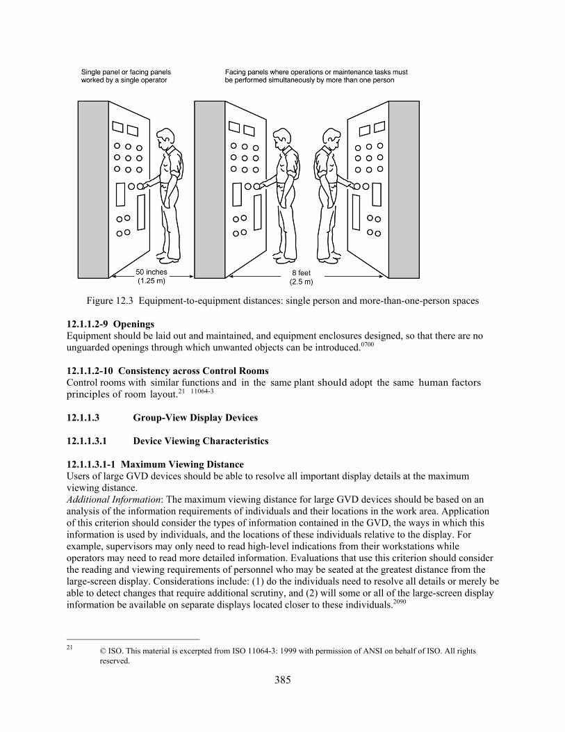
385
Figure 12.3 Equipment-to-equipment distances: single person and more-than-one-person spaces
12.1.1.2-9 Openings Equipment should be laid out and maintained, and equipment enclosures designed, so that there are no unguarded openings through which unwanted objects can be introduced.0700 12.1.1.2-10 Consistency across Control Rooms Control rooms with similar functions and in the same plant should adopt the same human factors principles of room layout.21 11064-3 12.1.1.3 Group-View Display Devices 12.1.1.3.1 Device Viewing Characteristics 12.1.1.3.1-1 Maximum Viewing Distance Users of large GVD devices should be able to resolve all important display details at the maximum viewing distance. Additional Information: The maximum viewing distance for large GVD devices should be based on an analysis of the information requirements of individuals and their locations in the work area. Application of this criterion should consider the types of information contained in the GVD, the ways in which this information is used by individuals, and the locations of these individuals relative to the display. For example, supervisors may only need to read high-level indications from their workstations while operators may need to read more detailed information. Evaluations that use this criterion should consider the reading and viewing requirements of personnel who may be seated at the greatest distance from the large-screen display. Considerations include: (1) do the individuals need to resolve all details or merely be able to detect changes that require additional scrutiny, and (2) will some or all of the large-screen display information be available on separate displays located closer to these individuals.2090
21 © ISO. This material is excerpted from ISO 11064-3: 1999 with permission of ANSI on behalf of ISO. All rights
reserved.

386
12.1.1.3.1-2 Minimum Viewing Distance If the observer is expected to be able to view the entire display at one-time, large group-view devices should not be closer to any observer than half the display width or height, whichever is greater.5908 12.1.1.3.1-3 Off-Centerline Viewing Angle The determination of the acceptability of off-centerline viewing for large group-view devices should consider both the spatial distortion of the image and the effect of the viewing angle upon screen characteristics such as brightness and color rendition. Additional Information: Individual viewers in a fixed location should be no more than 10 degrees off the centerline. For multiple viewers, the preferred limit should be 20 degrees and an acceptable limit should be 30 degrees off the centerline. These angle limits address spatial distortion of the displayed image caused by the viewing angle. However, off-centerline viewing of large-screen display devices may also result in (1) loss of general brightness for high-gain screens, and (2) loss of color rendition in projection-type devices caused by the angles of reflection of the separate projection elements. All these factors should be considered.5908, 2090 12.1.1.3.1-4 Projected Display Viewing Angles for Projected Displays The determination of the acceptability of off-centerline viewing for large projected display devices should consider the unique optical characteristics of the projection screen. Additional Information: High-gain projected display screens should have an off-centerline viewing angle of less than 25 degrees for beaded screens and less than 30 degrees for high-gain metallic screens. Loss of general brightness for high-gain projected screens is usually not a problem until these limits have been exceeded. Excessive viewing angles may further reduce perceived resolution by reducing the effectiveness of color codes and image contrast on projected screens. Thus, the combined effects of off-centerline viewing upon image distortion and screen characteristics should be considered.5908, 2090 12.1.1.3.1-5 Viewing of Multiple Display Devices When multiple, large display devices are used, the normal work areas of each user should be within the acceptable off-centerline viewing area of each large display that each user must view. Additional Information: If the large display devices are adjacent to each other, they should be angled toward each other so the acceptable off-centerline viewing areas of the displays overlap. If the operators’ tasks require them to work at multiple locations in the control room, the acceptable viewing area should be maximized by angling the display surfaces toward each other so that the acceptable off-centerline viewing areas of each display device coincide to the greatest extent possible.2090 12.1.1.3.1-6 Unobstructed View Seating areas should be arranged to provide critical observers with unobstructed views of the GVD. Additional Information: Large-screen displays should be located relative to critical observers so that the view is not obscured by other people. There are two methods for achieving this: (1) laterally staggering (offsetting) personnel and consoles to maintain an unobstructed view and (2) elevating the line of sight of personnel (e.g., supervisors) who are located farther from the display, so they may see over the heads of personnel located closer to the display. The line of sight may be elevated by using raised or inclined floors or by raising the height of the screen.5908, 2090 12.1.1.3.1-7 Externally Illuminated Displays Externally illuminated large displays, such as large status mimics, should have adequate illumination either from the control room environment or by means of local dedicated lighting, or both. Additional Information: Large displays that are primarily illuminated by external sources should satisfy the relevant criteria in Section 12.1.2.3 for illumination levels, illumination uniformity, task area illumination, shadowing, glare, reflectance, and color. The level of illumination should provide adequate contrast to allow users to resolve all important displayed details at the maximum viewing distance. 2090

387
12.1.1.3.1-8 Superposed Characters for Projected Displays The contrast polarity of superposed characters should be appropriate for the method of projection. Additional Information: For subtractive superposition (at the source), characters should be presented as dark markings on a transparent background. For additive superposition (at the screen), characters should be presented as light markings on an opaque background. Colored markings against colored backgrounds of comparable brightness should be avoided.5908 12.1.1.3.1-9 Luminance Ratio for Projected Displays The luminance ratio provided by the projection system should be adequate for the type of material being projected. Additional Information: The contrast ratio is defined as image or subject luminance divided by the nonimage or background luminance. Under optimal ambient lighting conditions, the contrast ratio for optically projected displays should be 500:1. Minimum contrast ratios are as follows: • For viewing charts, printed text, and other linework using slides or opaque projectors, the
minimum contrast ratio is 5:1. • For projections that are limited in shadows and detail, such as animation and photographs with
limited luminance range, the minimum contrast ratio is 25:1. • For images that show a full range of colors (or grays in black-and-white photographs), the
minimum contrast ratio is 100:1. 5908 12.1.1.3.1-10 Image Luminance for Projected Displays Image luminance and light distribution should be uniform. The luminance of the screen center at maximum viewing angle should be at least half its maximum luminance.5908 112.1.1.3.1-11 Minimize Keystone Effects for Projected Displays If projected displays are used, projector and screen should be arranged so as to minimize the “keystone effect” (i.e., distortion of projected data proportions caused by nonperpendicularity between projector and screen.5908 12.1.1.3.2 Information Display 12.1.1.3.2-1 Text Size For large GVD devices, the size of text for labels and detailed information on the screen should be based on analyses of the maximum viewing distances of personnel. Additional Information: The height of letters and numerals should typically not subtend less than 16 minutes of visual angle as measured at the maximum viewing distance. However, the maximum viewing distance may be different for different types of information in the display. For example, labels and high-level status indications may require larger viewing distances (e.g., across the control room) while individual parameter values may require shorter viewing distances (e.g., must be legible from panels that contain the corresponding controls). Therefore, the determination of acceptable text size should consider the type of information and the context in which it will be used. 2090
12.1.1.3.2-2 Labels For large GVD devices, the presence of labels on the screen should not hinder the visual search and recognition of detailed information. Additional Information: Because labels may be large and may require large separations, they tend to

388
clutter large displays. The need for labels may be reduced if graphic means such as mimics and symbols are used to identify information. 2090
12.1.1.3.2-3 Use of Information Displays Developed for Standard Video Display Units Information displays developed for standard visual display devices should not be presented on large GVD devices without first being evaluated for acceptability. Additional Information: Large GVD devices may have lower brightness and resolution than standard visual display devices and are more susceptible to glare from ambient light sources. These characteristics may result in reduced legibility and reduced effectiveness of color coding schemes. Text, graphics, and color codes should be reviewed and adjusted to suit the characteristics of the particular display device.2090
12.1.1.3.3 Integration into the Control Room 12.1.1.3.3-1 Glare and Reflections on the Display If VDUs are used for GVDs, either singly or in arrays, the visual environment in the control room should not be degraded by glare and reflections. Additional Information: See the relevant portions of Section 12.1.2.3, “Illumination,” concerning illumination, glare, and reflections on display screens. HFDS 12.1.1.3.3-2 Architectural Considerations The architectural design of the control room should consider the unique requirements of large GVD devices. Additional Information: The following architectural design characteristics should be considered if large GVD devices are to be used in the control room: • Workstation and equipment surfaces near GVDs should be controlled (so as not to be highly
reflective) to avoid interfering with the visibility of parts of the GVD.
• Entrances and exits should not be located within the same field of view as major GVDs.
• Windows should not be located adjacent to GVDs or within the same field of view.
• Artificial room lighting should not interfere with the visibility of any sections of the GVD.22 11064-3 12.1.1.4 Document Organization and Storage 12.1.1.4-1 Accessibility The control room should have a location for storage of all procedures and other documents that may be needed for ready reference so they are easy to locate and retrieve. Additional Information: Reference documents should not be locked up or stored in places too low or too high for large or small personnel to access easily, in cramped spaces, or where poor illumination exists.0700 12.1.1.4-2 Location Aids Clearly visible title labels should be provided to identify specific documents. Labels should distinguish documents as much as possible. Additional Information: Putting many volumes in one location creates a search problem, especially if 22 © ISO. This material is excerpted from ISO 11064-3: 1999 with permission of ANSI on behalf of ISO. All rights
reserved.

389
titles are similar. One means of reducing search time would be to put operational documentation in one location and other documentation in a secondary location.0700 12.1.1.4-3 Convenience of Use Documents should not be fixed in racks; it should be possible to remove documents for use.0700 12.1.1.4-4 Bound Documents Documents should be bound so that they can be opened fully and will remain open at the desired place without holding.0700 12.1.1.4-5 Protection Documents should be protected from wear so that they do not become dog-eared, dirty, loose, torn, or difficult to read.0700 12.1.1.5 Emergency Equipment 12.1.1.5.1 Personnel Protective Equipment 12.1.1.5.1-1 Types of Equipment Protective equipment should include protective clothing and breathing apparatus.0700 12.1.1.5.1-2 Anthropometry Protective clothing and breathing equipment should be compatible with users’ body sizes and tasks to provide adequate tactile sensitivity and ability to see, reach, move, communicate, and hear.0700 12.1.1.5.1-3 Periodic Checks Protective equipment should be in good condition.0700 12.1.1.5.1-4 Quantity There should be protective equipment available in sufficient quantities and sizes for the required number of users.0700 12.1.1.5.1-5 Marking Protective clothing sizes should be clearly identifiable.0700 12.1.1.5.1-6 Expendables There should be an adequate supply of personal protection equipment expendables, such as filters.0700 12.1.1.5.1-7 Accessibility All protective equipment should be easily and readily accessible.0700 12.1.1.5.1-8 Procedures Instructions for donning, doffing, and controlling personal protective equipment should be provided.0700 12.1.1.5.2 Fire, Radiation, and Rescue Equipment 12.1.1.5.2-1 Periodic Checks All equipment should be in good condition.0700 12.1.1.5.2-2 Accessibility All equipment should be easily and readily accessible.0700
390
12.1.1.5.2-3 Procedures There should be a written, administratively approved procedure for equipment use.0700 12.1.1.5.2-4 Automatic Warning System There should be an automatic fire warning system for control room fires.0700 12.1.1.5.3 Emergency Equipment Storage 12.1.1.5.3-1 Proper Storage Provision should be made for the orderly storage in the control room of emergency equipment that is needed by control room personnel.0700 12.1.1.5.3-2 Storage Locations The storage location(s) may be away from the main operating area but should be accessible, clearly marked, and known to all personnel.0700 12.1.1.6 Supervisor Access 12.1.1.6-1 Access The shift supervisor’s office should be located so as to permit prompt physical access to the control room under all conditions, including control room isolation. Additional Information: The preferred location is within the control room isolation boundary, with placement to permit good visual and voice contact with the main operating area.0700 12.1.1.6-2 Communications Dedicated communications links should be provided between the main operating area and the shift supervisor’s office when the shift supervisor’s office is not within the control room boundary.0700 12.1.1.7 Visitor Viewing Areas and Security 12.1.1.7 -1 Sensitive Information It should not be possible to see sensitive information in the control room from visitor viewing areas.23 11064-3 12.1.1.8 Spare Parts, Operating Expendables, and Tools 12.1.1.8-1 Supply There should be an adequate supply of expendables and spare parts (e.g., fuses, bulbs, ink and inking pens, recorder charts, and printer paper). Additional Information: Spare parts, such as indicator lamps, and any tools that are needed by operating personnel should be stored in suitable, designated space(s) within the control room.0700 12.1.1.8-2 Accessibility Expendables and spare parts should be readily accessible.0700 12.1.1.8-3 Tools All tools necessary to install expendables and spare parts should be available.0700 23 © ISO. This material is excerpted from ISO 11064-3: 1999 with permission of ANSI on behalf of ISO. All rights
reserved..

391
12.1.1.8-4 Storage Space There should be adequate storage space for expendables and spare parts.0700 12.1.1.8-5 Coding When different types, sizes, or styles of expendables and spare parts are required, they should be clearly and distinctively marked to avoid misapplication.0700
12.1.1.9 Maintenance 12.1.1.9 -1 Maintenance Independence Workplaces, controls, and displays that are primarily associated with maintenance activities should be separate from operator workplaces, controls, and displays. Additional Information. Controls and displays that are solely for maintenance should be readily accessible when needed by maintenance personnel without being visible to the operators. HFDS 12.1.1.9-2 Maintenance Interfaces Workspace and interfaces for accessing maintenance information systems and maintenance communication systems should be provided where these special maintenance linkages are essential to maintain the system. HFDS 12.1.1.10 Ambience and Comfort 12.1.1.10-1 Decor Decor should create a pleasant working environment in the control room. Additional Information: Features to be considered include the following: • color coordination • use of color and lighting to create a cheerful atmosphere (without introducing glare and
brightness to a degree that causes eye fatigue or an overly intense atmosphere) • visual relief from arrays of instrumentation • comfortable and sufficient seating • carpeting to lessen the fatigue of standing and walking 0700 12.1.1.10-2 Restroom and Eating Facilities A restroom and kitchen or eating area should be provided within (preferably) or near the control room isolation boundary. Additional Information: Since formal breaks are not scheduled in most control rooms, it is important that personnel have access to these facilities without delay. It is preferable that they be used only by control room personnel. Provision should be made for communication if facilities are out of voice contact, so that an operator taking a break can be contacted as necessary by personnel in the control room (see Guideline 10.2.6-2).0700 12.1.1.10-3 Rest Area or Lounge Consideration should be given to providing a rest area (possibly in conjunction with the eating area) conducive to relaxation and revitalization, especially where shifts are long.0700

392
12.1.1.10-4 Storage Locations There should be a suitable, out-of-the-way but secure place in which control room personnel may keep their coats and other personal belongings.0700 12.1.1.10-5 Storage Suitability If lockers are provided, they should be large enough to hold the items that might reasonably be expected to require storage.0700 12.1.1.11 Multiunit Control Rooms 12.1.1.11-1 Equipment Arrangement Equipment should be arranged with movement and communication patterns in mind so that unit operations do not interfere with each other.0700 12.1.1.11-2 Senior Operator Station Senior operators who supervise and assist operations of more than one unit should be stationed so that they can communicate effectively with operators in each unit and have an unobstructed visual path to the workstations of each unit.0700 12.1.1.11-3 Sharing of Procedures Each unit should have its own set of procedures and other reference documents, as required, to make sure that references are easily available to personnel in each unit and to avoid conflicting needs for the same reference.0700 12.1.1.11-4 Shared Equipment When control of some plant equipment is shared by the control rooms of multiple-unit nuclear power plants, care must be taken to ensure that status and availability data for this equipment are available in each control room and that equipment operation from the control room for one unit will not affect other unit operations. Additional Information: Control of plant equipment from one control room should not affect the ability of operators in other control rooms to maintain control of their respective units. The status of plant equipment under the control of one control room should be displayed in all control rooms capable of controlling that equipment. If control of plant equipment from one control room renders that equipment unavailable to other control rooms, availability status indications should be displayed in all control rooms. A single, centrally located control panel or console may be used for dual-unit control rooms within the same isolation boundary when this design does not conflict with the panel layout and control-display integration guidelines of Section 11.2. Administrative procedures should be in place that assign responsibility for use of controls of shared plant equipment to a single control room.0700 12.1.1.11-5 Mirror Image Layouts Control rooms should not be designed as mirror images of each other (i.e., with the control boards of two units laid out symmetrically, side-by-side, so that one is a complete or nearly complete reversal of the other. Additional Information: Operators who work both units have to deal with two opposite patterns of controls and displays and must reorient their expectations completely when they switch from unit to unit. This requirement violates the principle of positive transfer of training and is highly unfavorable for task performance reliability. It is also inconsistent with the guidance on consistent layout principles (see Guideline 12.1.1.2-10, “Consistency across Control Rooms.” The potential for confusion is greater when the reversal is incomplete (e.g., control boards are mirror imaged but annunciator panels are arranged identically in both units). Therefore, when mirror image control rooms exist, operational crews should be
393
committed to one or the other unit and should not be allowed to alternate between the two mirrored units.0700 12.1.1.11-6 Accentuate Differences The distinction between the mirrored units should be heightened as much as possible so that there will be no confusion about where one unit ends and the other begins. Additional Information: In addition to using labeling, distinctiveness can be increased by using a different color scheme for the elements of each unit, including carpeting, desks, and other work station equipment, as well as the board surface areas.0700 12.1.1.12 HSI Upgrades 12.1.1.12-1 Consistent System Response The system’s interpretation of a user input should not change as a result of an upgrade. Additional Information: For example, a given keystroke should not produce a benign action in one version of the system software and a destructive action, such as erasing data, in a subsequent version.6546 12.1.1.12-2 Existing Skills Preserved Changes to HSI hardware or software should not force users to have to unlearn existing skills. Additional Information: It is better for an upgrade to require the user to learn additional skills than to expect the user to change existing ones. Thus, changes in the information presented by the system (e.g., messages, graphic symbols) are less difficult to adapt to if they do not require users to modify their skills or strategies. For example, changes limited to physical appearance do not typically seriously disrupt users’ performance, whereas changes in the operation of the system almost certainly will. However, sometimes the appearance of a system is strongly linked to user skills. For example, the layout of tools on the palette of a drawing program should not be changed in subsequent versions. Users who rely on spatial memory for retrieving tools from the palette will find that this skill leads them to select the wrong tool.6546
12.1.1.12-3 Salient Changes If changes must be made to the HSI, they should be salient. Additional Information: Drawing the user’s attention to characteristics that have changed can help them to adapt their skills. For example, injecting a single new word into a message is not recommended. Adding the word “not” to a question, such as “Do you want to save these settings?” will change the meaning of the message. However, it may not be detected by the user until an error occurs. Many actions become automatic as users become skilled in using the interface. If HSI changes are obvious, users may be able to block their automatic responses and develop new ones.6546
12.1.2 Control Room Environment 12.1.2.1 Temperature and Humidity 12.1.2.1-1 Ambient Temperature The climate control system should maintain control room ambient temperatures of 20–24°Celsius (C)) (68–75 degrees Fahrenheit (F) in winter and 23–26 degrees C (73–79 degrees F) in summer. Additional Information: The above temperature ranges are based upon calculations of the human comfort zones. In the summer thermal comfort zone, workers wearing light clothing will be comfortable; in the winter thermal comfort zone, workers wearing heavy indoor clothing (e.g., sweaters) will be comfortable. These comfort zones assume sedentary work; personnel performing “light work” (e.g., actively monitoring spatially distributed equipment or retrieving procedures or manuals) will be comfortable at higher and lower temperatures, respectively. Air movement rates of less than 0.25 m/second

394
(50 ft/minute) are also assumed. More information on comfort zones may be found in ISO 7730 (2005) and ANSI/ASHRAE 55 (2013).0700, 5680 12.1.2.1-2 Relative Humidity The climate control system should maintain the relative humidity in the control room in the range of 30 to 70 percent, with 40 to 45 percent preferred. The design goal for relative humidity should be 45 percent for an ambient temperature of 21–25 degrees C (70–77 degrees F). Additional Information: A minimum relative humidity of 15 percent should be maintained to prevent irritation and drying of body tissues; for example, eyes, skin, and respiratory tract.1472G, HFDS
12.1.2.1-3 Effective Temperature The temperature in the control room should be maintained in the comfort zone of its users. Additional Information: The temperature metric used to determine the control room climate under “Ambient Temperature” above represents the dry-bulb temperature and should be used as the primary criterion for determining temperature conformance in the control room. However, the dry-bulb temperature metric has certain limitations with regards to human comfort. Calculating individual heat balances in the workplace is difficult. If the dry-bulb temperature metric proves to be inadequate, or if a more in-depth analysis is needed, for certain types of control room climate conditions, especially as regards extremes in relative humidity and air movement, the more comprehensive effective temperature (ET) metric should be used. The ET considers dry-bulb temperature and wet-bulb temperature (and derived relative humidity), as well as air movement, to more accurately determine the comfort zone, which itself can vary depending on user clothing, workloads, and acclimatization. The optimum range of ET for accomplishing light work while dressed appropriately for the season or climate is 21–27 degrees C (70–80 degrees F) in a warm climate or during the summer, and 18–24 degrees C (65–75 degrees F) in a colder climate or during the winter. More information on the ET metric may be found in ANSI/ASHRAE 55 (2013).HFDS 12.1.2.1-4 Vertical Temperature Differential For primarily analog control rooms, air temperature at floor level and at head level (standing user) should not differ by more than 5.6 degrees C (10 degrees F). For primarily computer-based control rooms, the vertical air temperature difference between the seated head and ankle level, 1.1 to 0.1 m (43.3 to 3.9 in.) above the floor, should be less than 3 degrees C (5.4 degrees F).24 0700, 11064-6 12.1.2.1-5 Floor Temperature In the winter, the surface temperature of the floor should normally be 19–26 degrees C (66–79 degrees F); however, floor heating systems can have a surface temperature of up to 29 °C (84°F).24 11064-6 12.1.2.1-6 Side Wall Temperatures In winter, the side walls of the control room should be kept at equal temperatures as much as possible; however, temperature differences of 11 degrees C (20 degrees F) or less do not significantly degrade comfort.1472G 12.1.2.1-7 Temperature Asymmetry In winter, the radiant temperature asymmetry from windows or other cold vertical surfaces should be less than 10 degrees C (18 degrees F), in relation to a small vertical plane located 0.6 m (2 ft) above the floor.23 11064-6
24 © ISO. This material is excerpted from ISO 11064-6: 2005 with permission of ANSI on behalf of ISO. All rights
reserved.

395
12.1.2.1-8 Control of Temperature and Humidity The control room should have its own individual thermostat to regulate temperature and dehumidification.1472G 12.1.2.1-9 Diurnal Rhythms
Control room users should be able to increase control room temperatures by 12 degrees C (1.8–3.6 degrees F) in the early hours of the morning. Additional Information: This is to compensate for diurnal rhythms.24 11064-6 12.1.2.1-10 Thermal Shock To limit thermal shock to users moving in and out of the control room, buffer zones should be considered as a way to offer an intermediate temperature.24 11064-6 12.1.2.2 Ventilation and Air Quality 12.1.2.2 -1 Air Exchange The ventilation system should be capable of introducing fresh air into the control room at a rate of at least 9.4 l/s (20 cubic feet (ft3)/min) per occupant. Additional Information: In general, the rate of air exchange for enclosed spaces should be at least six complete air changes per hour. For crowded spaces with an enclosure volume of 4.25 cubic meters (m³)(150 ft³) or less per person, a minimum of 0.85 m³ (30 ft³) of ventilation air per minute per person should be introduced into the enclosure, with approximately two-thirds of that volume consisting of outdoor air. For larger enclosures, the air supply rates per person, as well as the proportion of outdoor air, should be in accordance with Figure 12.4. 0700, 5680, 1472G
Figure 12.4 Minimum ventilation requirements (Source is Figure 34 in MIL-STD 1472G, 2012)
12.1.2.2-2 Air Velocity Air velocities in the main operating area should not exceed 8.8 m/min (29 ft/min), measured at head level, and should not produce a noticeable draft.25 11064-6, 0700
25 © ISO. This material is excerpted from ISO 11064-6: 2005 with permission of the American National Standards
Institute (ANSI) on behalf of the International Organization for Standardization. All rights reserved.

396
12.1.2.2-3 Drafts from Heating, Ventilation, and Air Conditioning Systems Heating, ventilation, and air conditioning (HVAC) systems should be designed such that hot or cold air discharge is not directed on personnel.1472G
12.1.2.2-4 Internally Generated Pollutants The control room should be supplied with outdoor air in sufficient quantities to dilute internally generated pollutants.25 11064-6 12.1.2.2-5 Carbon Dioxide Concentration Carbon dioxide concentrations in the control room should be maintained at levels below those that could result in user performance decrements or adverse health effects. Additional Information. Carbon dioxide concentrations should not exceed 1.8 grams per cubic meter (g/m3)(910 parts per million (ppm)) when the control room is at full occupancy.25 11064-6 12.1.2.2-6 Harmful Substances Ventilation or other protective measures should be provided to keep gases, vapors, dust, and fumes within the permissible exposure limits specified by 29 CFR Part 1910.1472G 12.1.2.2-7 Fresh Air Contamination Intakes for ventilation systems should be located to minimize the introduction of contaminated air from such sources as exhaust pipes. 1472G 12.1.2.3 Illumination 12.1.2.3-1 General Illumination Levels The overall general illuminance levels on worksurfaces in the control room where paperwork is required should be in the range of 200–750 lux (18.6–69.7 foot-candles (fc)). If visual display devices are used at the workstation, as in computer-based control rooms, the maximum illuminance should be 500 lux (46.5 fc). For areas where tasks consist largely of paperwork, a minimum illuminance of 500 lux (46.5 fc) should be maintained. Additional Information: These general illuminance values can be accomplished by a combination of ambient and task lighting.26 11064-6 12.1.2.3-2 General Illumination Dimming For the computer-based control room, the overall general illuminance levels in the control room should be capable of dimming from the maximum illuminance supplied by the lighting system down to a minimum value of 200 lux (18.6 fc). If no significant paperwork tasks are required, the dimming control minimum value may be lower. Additional Information: High-frequency dimming control devices should be used to avoid flicker.26 11064-6, 1472G 12.1.2.3-3 General Lighting Control Placement Lighting controls for illuminating and dimming the overall workplace should be provided at entrances and exits of enclosed workplace areas. 1472G 12.1.2.3-4 Task-Specific Illumination Levels For specific important tasks required to be carried out in the control room, the illuminance levels should
26 © ISO. This material is excerpted from ISO 11064-6: 2005 with permission of ANSI on behalf of ISO. All rights
reserved.
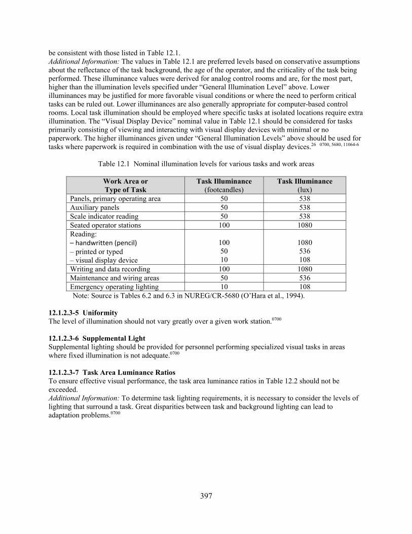
397
be consistent with those listed in Table 12.1. Additional Information: The values in Table 12.1 are preferred levels based on conservative assumptions about the reflectance of the task background, the age of the operator, and the criticality of the task being performed. These illuminance values were derived for analog control rooms and are, for the most part, higher than the illumination levels specified under “General Illumination Level” above. Lower illuminances may be justified for more favorable visual conditions or where the need to perform critical tasks can be ruled out. Lower illuminances are also generally appropriate for computer-based control rooms. Local task illumination should be employed where specific tasks at isolated locations require extra illumination. The “Visual Display Device” nominal value in Table 12.1 should be considered for tasks primarily consisting of viewing and interacting with visual display devices with minimal or no paperwork. The higher illuminances given under “General Illumination Levels” above should be used for tasks where paperwork is required in combination with the use of visual display devices.26 0700, 5680, 11064-6
Table 12.1 Nominal illumination levels for various tasks and work areas
Work Area or Type of Task
Task Illuminance (footcandles)
Task Illuminance (lux)
Panels, primary operating area 50 538 Auxiliary panels 50 538 Scale indicator reading 50 538 Seated operator stations 100 1080 Reading: – handwritten (pencil) – printed or typed – visual display device
100 50 10
1080 536 108
Writing and data recording 100 1080 Maintenance and wiring areas 50 536 Emergency operating lighting 10 108
Note: Source is Tables 6.2 and 6.3 in NUREG/CR-5680 (O’Hara et al., 1994). 12.1.2.3-5 Uniformity The level of illumination should not vary greatly over a given work station.0700
12.1.2.3-6 Supplemental Light Supplemental lighting should be provided for personnel performing specialized visual tasks in areas where fixed illumination is not adequate.0700
12.1.2.3-7 Task Area Luminance Ratios To ensure effective visual performance, the task area luminance ratios in Table 12.2 should not be exceeded. Additional Information: To determine task lighting requirements, it is necessary to consider the levels of lighting that surround a task. Great disparities between task and background lighting can lead to adaptation problems.0700

398
Table 12.2 Maximum task area luminance ratios
Areas Luminance Ratio Task area versus adjacent darker surroundings 3:1 Task area versus adjacent lighter surroundings 1:3 Task area versus more remote darker surfaces 10:1 Task area versus more remote lighter surfaces 1:10 Luminaires versus surfaces adjacent to them 20:1 Anywhere within normal field of view 40:1
12.1.2.3-8 Shadows To reduce fatigue and eyestrain, shadows should be avoided. Additional Information: Ambient illumination should be provided by indirect or diffuse lighting. Labels, instructions, and other written information should not be in shadowed positions.0700 12.1.2.3-9 Glare Glare should not interfere with the readability of displays, labels, or indicators. Additional Information: Glare increases the probability that an individual will misread a display or will fail to notice displayed information. Glare can also produce discomfort. Direct sources of glare include light emitted from luminaires, indicators, and displays. Indirect sources of glare include reflected light from all surfaces (e.g., paint, metal, and glass). The surface of a visual display device screen should reduce reflections. Positioning of visual display devices relative to light source affects glare as can the use of a shield or filter on the visual display device or light source. If glare reduction or contrast enhancement techniques are used, they should not violate the requirements of luminance, contrast, resolution, and other specifications for the visual display device itself in its installed configuration, as stated in Section 11.3.1. In cases where more detailed analysis of glare is required, the unified glare rating (UGR) should be employed. The UGR is a measure of the overall glare in an environment, considering both disability and discomfort glare. The UGR is the common logarithm of the sum of the luminances from all visible light sources, divided by the background luminance, with corrections for the solid angle of the light source and the distance from the line of sight of the observer. In general, the lighting system should achieve a maximum UGR of 19 or less for all work positions in the control room. Methods to calculate and evaluate the UGR may be found in ISO 8995-1 (2002). A tabular method of calculation and presentation of UGR data may be found in CIE 190 (2010).27 0700, 5908, 11064-6 12.1.2.3-10 Glare and the Use of Eyeglasses If users wear eyeglasses, bright light sources behind the user should be avoided. Additional Information: For users wearing eyeglasses, bright lights can cause glare if the sources are located behind the user between 30 degrees above and 45 degrees below the line of sight, or behind the user within 20 degrees left or right of the line of sight, since eyeglasses can reflect glare into the eyes of the user from such positions.1472G 12.1.2.3-11 Methods for Reducing Glare Since most visual work is at or below the horizontal position of the user’s eyes, luminaries should be placed high above the work area to minimize direct glare. Additional Information: The following techniques should also be considered to reduce glare: • using indirect lighting • using a greater number of relatively dim light sources 27 © ISO. This material is excerpted from ISO 11064-6: 2005 with permission of ANSI on behalf of ISO. All rights
reserved.

399
• using polarized light, shields, hoods, or visors to block the glare in confined areas 1472G 12.1.2.3-12 Diffuse Reflectance Diffuse reflectance should conform to the recommendations shown in Table 12.3. Additional Information: The amount of light reflected from a surface depends on its color; typical reflectance values for various colors are given in Table 12.4. Surfaces adjacent to a visual display device should have a dull matte finish to reduce glare. Large surface areas should be covered with nonsaturated colors, such as tints, pastels, and warm grays that are nonglossy. Some noncritical small areas such as door frames and molding may be glossy if ease of cleaning is essential. 0700, 5908, 1472G
Table 12.3 Recommended workplace reflectance levels
Surface Reflectances
Preferred Permissible Ceiling1 80% 60–95% Upper Wall 50% 40–60% Lower Wall 15–20% Instruments/Displays 80–100% Cabinets/Consoles 20–40% Floor 30% 15–30% Furniture 35% 25–45% 1 Recommended reflectances are for finish only. Overall average
reflectance of acoustic materials may be somewhat lower. The upper walls (one to two feet below the ceiling) may be painted with the same paint as is used on the ceiling.
Table 12.4 Surface color reflectance values
Color Reflectance (%)
White light Cream 75 Gray 75 Yellow 75 Buff 70 Green 65 Blue 55
Medium Cream 75 Gray 75 Yellow 75 Buff 70 Green 65
Dark Gray 30 Red 13 Brown 10 Blue 8 Green 7
Wood finish Maple 42 Satinwood 34 English Oak 17 Walnut 16 Mahogany 12
400
12.1.2.3-13 Specular Reflection Bright spots caused by specular reflection should be avoided. Additional Information: Specularity can be determined by relative specular reflectance measurements. Under a given lighting configuration, the reflectance of a highly reflective reference surface is taken to be 100 percent, and the reflectance of the surface being evaluated is compared with respect to this reference sample. Work surface reflection should be diffuse and should not exceed 20-percent specularity. To reduce glare, nonreflective or matte finished surfaces should be provided on consoles, panels, and other work surfaces. Placement of smooth, highly polished surfaces within 60 degrees of a person’s normal visual field should be avoided.1472G
12.1.2.3-14 Color Rendering The lighting system should have good color rendering capability. Surface colors, as well as colors on visual display devices, should be recognizable under both normal and emergency lighting conditions. Additional Information: Colored ambient illumination should not be employed if color coding is used in the workplace, since such illumination can interfere with color coding. Some types of lamps (e.g., mercury or sodium lamps) have very poor color rendering properties. These types of lamps should not be used for normal or emergency lighting if the ability to distinguish among colors may be important. The color rendering index (CRI) is a method of measuring and specifying the color rendering properties of light sources based on the resultant color shifts of test objects. This method employs a set of test-color samples specified by their spectral radiance characteristics. The CRI is determined from the measured color shifts of these samples relative to the colors rendered by an ideal black body radiator light source, in this case, the D series of illuminants constructed to represent natural daylight. In general, the lighting system should achieve a minimum CRI of 80 or more. Methods to calculate and evaluate the CRI may be found in CIE 13.3 (1995).28 0700, 5680, 5908, 11064-6 12.1.2.3-15 Ambient Illumination and Visual Display Devices The ambient illumination in the visual display device area that is necessary for other visual functions (e.g., setting controls, reading instruments) should not degrade the visibility of information on the visual display device.0700, 5908 12.1.2.3-16 Light Sources in Areas Surrounding Visual Display Devices There should be no light source (direct or reflected) in the immediate surrounding area of the visual display device that is of substantially greater luminance than the visual display device screen. Additional Information: Outside the immediate display area, but still in the visual field of the user, the luminance from other light sources that subtend an arc of greater than 5 degrees should: (1) not exceed 10 times the average screen luminance for negative-polarity screens (bright characters on dark background), and (2) not exceed 3 times the average screen luminance for positive-polarity screens (dark characters on bright background). For negative-polarity screens, the best visual performance occurs when the background luminance is approximately 5 times the average screen luminance. For positive-polarity screens, the best visual performance is obtained when the background luminance is approximately equal to the average screen luminance. 0700, 5908, 100 12.1.2.3-17 Minimize Reflections on Screens Luminaires and bright room surfaces should not produce significant reflections on the screens of visual display devices. Additional Information: Where visual display devices are used, the average luminance of luminaries and bright room surfaces should not exceed 1,000 candelas per square meter, cd/m2 (292 foot-lamberts (ft-L)) 28 © ISO. This material is excerpted from ISO 11064-6: 2005 with permission of ANSI on behalf of ISO. All rights
reserved.
401
for display screens with good or moderate screen glare treatment and should not exceed 200 cd/m2
(58.4 ft-L) for display screens with no screen glare treatment.28 11064-6 12.1.2.3-18 Indirect Lighting Systems For indirect lighting systems, ceilings should have sufficient reflectance to efficiently illuminate the room but not have excessive brightness or variation in brightness from luminaires. Additional Information: For indirect lighting systems, ceilings should be white, should be of matt finish, and should have a minimum surface reflectance of 0.8. In addition, the average luminance on the ceiling, or on other surfaces lit directly, should not exceed 500 cd/m2 (146 ft-L); the peak luminance should not exceed 1,500 cd/m2 (438 ft-L); and the luminance should vary gradually across the surfaces being directly lit.28 11064-6 12.1.2.3-19 Location of Lighting Fixtures Lighting fixtures should not be placed in locations that are difficult to reach for bulb replacement or other maintenance.1472G 12.1.2.3-20 Flicker of Lighting Sources Light sources should not have a perceptible flicker.1472G 12.1.2.3-21 Portable Lighting Portable lighting should be provided for personnel performing visual tasks in areas where fixed illumination is not provided (e.g., inside consoles or backpanels). Additional Information: A supply of fresh batteries should be stored near portable lighting devices. Portable lighting devices should conform to ANSI/National Electrical Manufacturers Association (ANSI/NEMA) FL-1 (2009) as concerns the methodology for testing, measuring, and rating the basic performance of flashlights, headlamps, spotlights, and portable lighting tools. 1472G, 0700, 0700, 6146 12.1.2.4 Emergency Lighting 12.1.2.4 -1 Automatic Action A control room emergency lighting system should be automatically activated and immediately available upon loss of power or failure of the normal control room lighting system. Additional Information: This system should be independent of any other plant lighting system that is available in the control room.0700
12.1.2.4-2 Operability Failure of the normal control room lighting system should not degrade the operability of the emergency lighting system.0700
12.1.2.4-3 Duration of Operation The duration of emergency lighting should be commensurate with the duration of time that users are expected to maintain task performance within the control room (for the conditions under which the lighting was lost).1472G 12.1.2.4-4 Emergency Lighting Levels The control room emergency illumination system should be designed to provide a minimum illumination level of 108 lux (10 fc) at all work stations in the main operating area. Additional Information: Higher levels of illumination are preferred if the room’s surfaces are of low reflectivity or the occupants of the room may be over 40 years of age.0700

402
12.1.2.5 Auditory Environment 12.1.2.5 -1 General Guidance The acoustic design of the control room should ensure that oral communications among personnel are not impaired; auditory signals are readily detected; and auditory distraction, irritation, and fatigue are minimized.0700
12.1.2.5-2 Oral Communications Background noise should not impair oral communication between any two points in the main operating area of the control room. Additional Information: Figure 12.5 shows the voice levels needed for oral communication over specified distances in the presence of different levels of background noise. Intelligibility of oral communication in noise is affected by the frequency spectra of the noise and of the speakers’ voices and by the speakers’ hearing sensitivity. The decibel on the A-weighted scale (dB(A)) metric employed to measure room noise in these examples should be used as the primary criterion for determining noise conformance. However, the dB(A) metric has certain limitations. If the dB(A) metric proves to be inadequate, for certain types of control room noise environments, especially as regards HVAC noise, the more comprehensive noise criteria (NC) rating method should be used. The NC method uses octave band sound spectra to account for unusual sound spectrum shapes and relates the measured spectra to modified equal-loudness contours whose shapes are level sensitive. The NC rating metric is extensively used in architectural acoustics. In work areas where good voice communications and habitability are required, the octave-band sound pressure levels (SPLs) of continuous noise (not including impulse noise) should be limited to the values given by the NC-50 curve. ANSI/ASA S12.2 (2008) contains more information on the NC rating method. 0700, 5680
Figure 12.5 Oral communication level as a function of distance and ambient noise level
12.1.2.5-3 Background Noise Reductions Where communications between the main operating area and other control room locations are necessary, and voice transmission systems are not provided, further reductions in background noise should be implemented.0700

403
12.1.2.5-4 Acoustical Environment around Computer Workstations The acoustic environment around computer workstations should allow oral communication and aid concentration. Additional Information: The maximum ambient noise levels specified in dB(A) under “Background Noise” above should be used as the primary criterion for determining noise conformance around the computer workstation. If the dB(A) metric proves to be inadequate, or if a more in-depth analysis is needed, for certain types of noise environments, especially as regards unbalanced or rumbly sound spectra, the more comprehensive balanced noise criteria (NCB) rating method should be used. The NCB method represents an enhancement of the NC method described above. The NCB method accounts for unbalanced sound spectrum shapes and extends down to 16 hertz (Hz) to include low frequency noise components commonly found in many rooms. It also relates these spectra to speech interference levels (SILs) and corrects for rumbly spectra. The maximum level of background noise emissions from a computer workstation and its components should have an NCB rating ranging between 38 and 43, and strive to achieve an NCB rating as low as possible within this range. These NCB values assume occupied spaces, with the HVAC system operating and all other sources of normal and interior and exterior noise also operating. Such values do not interfere with oral communication and provide an environment quiet enough to aid concentration on mental tasks. More information on the NCB rating method may be found in ANSI/ASA S12.2 (2008).100 12.1.2.5-5 Noise Distractions Noise distractions generated either inside or outside the control room should be minimized. Additional Information: One method to control both ambient noise and noise distractions emanating from outside the control room is to acoustically insulate the control room from surrounding building enclosures. Transmission of excessive noise into the control room should be attenuated by means of high-density and multilayer sound-attenuating materials (e.g., concrete, gypsum board, and high-density sound-absorbing ceiling tiles). Transmission of noise should be further attenuated by sound reducing construction techniques (e.g., staggered seams in walls, acoustic caulking of walls to the hard structure of the floor and ceiling but not to a suspended ceiling, acoustic attenuators placed in HVAC supply and return ducts, sound-absorbing doors, and multipaned windows. Wherever possible, these materials and building systems should be rated by sound transmission class (STC). Many manufacturers of sound-attenuating barriers specify the STC rating of their products or systems. The STC measures the sound transmission loss (TL) of an acoustic barrier in 1/3 octave bands from 125 Hz to 4,000 Hz. The TL spectrum is then compared to a reference STC curve and the STC rating of the barrier is read as the 500-Hz value of the appropriate STC curve. The STC is designed primarily to correlate with the perception of oral communication through acoustic materials or systems. For example, with an STC = 25–35, conversation can generally be heard and understood through the barrier, whereas with an STC = 55–65, most external noise sources are rendered inaudible. American Society for Testing and Materials (ASTM) E90 (2009) contains more information on the STC method. 0700, 1472G 12.1.2.5-6 Reverberation Time and Sound Absorption Where oral communication is a consideration, the acoustical treatment in the control room should be sufficient to reduce reverberation time below the applicable limits shown in Figure 12.6. Additional Information: Excessive reverberation in rooms and at workstations should be controlled by applying materials with a high coefficient of sound absorption to various room surfaces, such as coverings on the floor (e.g., carpets), acoustical tiles on the ceiling, and sound absorbing treatments on the walls (e.g., acoustical panels or thick drapes). Wherever possible, these sound absorbing materials should be rated by Noise Reduction Coefficient. Many manufacturers of such materials specify the Noise Reduction Coefficient of their products. The Noise Reduction Coefficient method measures the Sabine sound absorption coefficients ('”Sabine alphas”' or '”aSAB”') in octave bands from 125 Hz to 4,000 Hz. To generate a single-number rating, the Sabine alphas for 250, 500, 1,000 and 2,000 Hz are averaged to compute the Noise Reduction Coefficient. Theoretically, a Noise Reduction Coefficient = 0 indicates

404
perfect acoustic reflection (i.e., no acoustic absorption), and a Noise Reduction Coefficient = 1 indicates perfect acoustic absorption (i.e., no acoustic reflection). However, because of the averaging method employed, Noise Reduction Coefficient values slightly greater than one are sometimes observed. For example, ordinary drywall may have a Noise Reduction Coefficient of 0.2, while sound-absorbing ceiling tiles may have a Noise Reduction Coefficient between 0.9 and 1.0, or slightly higher than 1.0. The Noise Reduction Coefficient is being replaced by the Sound Absorption Average, but many commercial sound-absorbing products are still rated in terms of the Noise Reduction Coefficient. ASTM C423a (2009) contains more information on the Noise Reduction Coefficient method. 1472G
Figure 12.6 Acceptable reverberation times
(Source is Figure 39 in Mil-Std-1472G, 2012) 12.2 Local Control Stations 12.2.1 Local Control Station Configuration 12.2.1.1 Equipment Labeling 12.2.1.1.1 Placement of Labels 12.2.1.1.1-1 Labeling of Equipment Labels should appear on all components and systems with which personnel may interact.6146

405
12.2.1.1.1-2 Replacement of Labels When labels are affixed, earlier markings (such as labels applied during construction or acceptance, or informal labels) should be removed.6146 12.2.1.1.1-3 Viewing Direction When equipment may be approached from more than one direction, labels should be placed on surfaces so that they are visible from each direction.6146 12.2.1.1.1-4 Label Visibility Identifying labels should be placed so that they are readily visible at typical viewing distances and orientations. Additional Information: Labels should be placed to be visible to plant personnel of both short and tall stature. Guideline 12.2.1.1.2-3 gives recommended character sizes.6146 12.2.1.1.1-5 Locator Labels Readily visible markings should be placed nearby to indicate the location and identity of components that are partially blocked from view. Additional Information: The location of overhead valves can be indicated by labels on floors or walls directly below them.6146 12.2.1.1.1-6 Label Orientation Labels should be designed and mounted so that text is oriented horizontally for ease of reading. Additional Information: Requiring operators to manipulate and reorient the label is inconvenient (especially when their hands are full) and may lead to misreading.6146 12.2.1.1.1-7 Label Positioning Labels should be attached or positioned so as to unambiguously indicate the item being identified.6146 12.2.1.1.1-8 Redundant Labels When labels are placed on the doors of equipment cabinets, redundant labels should be placed inside so that they are visible when the door is open.6146 12.2.1.1.1-9 Label Placement Conventions Specific conventions for label placement should be employed for each type of equipment (e.g., valves, motors).6146 12.2.1.1.1-10 Label Mounting Tags should be attached to components so as not to cause damage or interfere with operation. Additional Information: Valve labels should not be connected to handwheels or operating chains. The wire used to attach a label to a valve should be passed through the yoke in a manner that will not damage the stem. For chain-operated valves, the label should be wired to a small piece of plastic pipe through which the operating chain passes freely.6146 12.2.1.1.1-11 Label Replacement after Maintenance Maintenance procedures should require personnel to check that labels are in place after components are reassembled or replaced.6146 12.2.1.1.1-12 Means of Label Attachment Labels and tags should be securely attached in a manner appropriate to the equipment and environmental conditions. Additional Information: The method chosen to attach a label should consider the possibility of exposure

406
to heat, corrosive substances, oil, or solvents.6146 12.2.1.1.2 Label Design 12.2.1.1.2-1 Label Material The material from which labels and tags are made should be appropriate to the equipment and environmental conditions. Additional Information: The material chosen should consider the possibility of exposure to heat, corrosive substances, oil, or solvents. A single label material may not be appropriate in all environments. If different label material is required at different locations in the plant, an effort should be made to keep the content and format of the labels constant.6146 12.2.1.1.2-2 Label Contrast Lettering and background colors should provide high contrast and high legibility. Additional Information: Dark letters on a light background are preferred. Table 11.9 provides examples of color combinations and their relative legibility. Stamped metal tags (brass, stainless steel, and color anodized aluminum) often are illegible under less-than-optimal conditions.6146 12.2.1.1.2-3 Character Height Characters used on labels should be sized to take into account viewing distances and illumination conditions. Additional Information: Table 12.5 gives character heights required for various viewing distances. Under less-than-optimal viewing conditions, the preferred values should be used as minima. The preferred values should also be used for critical markings associated with safety-related systems.6146
Table 12.5 Minimum and preferred character heights for various viewing distances
Viewing Distance Minimum Character Height Preferred Character Height feet (m) inches (mm)1 points2 inches (mm)3 points2
2.33 (0.71) 0.11 (2.84) 8 0.17 (4.27) 12 3 (0.91) 0.14 (3.56) 10 0.22 (5.49) 16 4 (1.22) 0.19 (4.88) 14 0.29 (7.32) 21 5 (1.52) 0.24 (6.10) 17 0.36 (9.14) 26 6 (1.83) 0.29 (7.32) 21 0.43 (10.97) 30 10 (3.05) 0.48 (12.19) 35 0.72 (18.29) 50 20 (6.10) 0.96 (24.38) 70 1.44 (36.58) 100 30 (9.14) 1.44 (36.58) 100 2.16 (54.86) 150 40 (12.19) 1.92 (48.77) 140 2.88 (73.15) 200 1 minimum character height (15minutes of arc) = distance multiplied by .004 2 character heights in points (1 point = 1/72 inch = 0.35 mm) are approximate 3 preferred character height (20 minutes of arc) = distance multiplied by .006
12.2.1.1.2-4 Stenciled Labels Stenciled labels should not be used. Additional Information: The gaps in stenciled characters render them less legible than other forms of labeling.6146 12.2.1.1.2-5 Label Reflectance Surfaces of labels should have a nonreflective (i.e., matte) finish. Additional Information: Reflective materials may be added to labels to aid locating equipment when normal lighting is lost. Such labels should be designed so that legibility is not impaired under normal

407
lighting conditions (e.g., a reflective border may be placed around the contents of the label).6146 12.2.1.1.3 Label Content 12.2.1.1.3-1 Label Information Labels should contain concise, descriptive noun names along with alphanumeric system and component identification codes. Additional Information: Labels should provide sufficient descriptive information to allow the least experienced operator to recognize the equipment. The following additional items may be considered for inclusion on labels: unit/train/channel designations, power supply information, operational characteristics, and flow direction.6146 12.2.1.1.3-2 Labeling Conventions Labeling conventions should be used to ensure consistency of plant labeling with drawings and procedures.6146 12.2.1.1.3-3 Standard Label Format The format of presentation (e.g., order, position) of information should be consistent on all labels.6146 12.2.1.1.3-4 Abbreviations Abbreviations used on labels should be standardized and easily recognized.6146 12.2.1.2 Communications 12.2.1.2.1 Loudspeakers 12.2.1.2.1-1 Range of Coverage of Loudspeakers Loudspeaker coverage should be such that members of the work force can be alerted under all plant conditions.6146 12.2.1.2.1-2 Coverage Areas of Loudspeakers Loudspeaker coverage should be provided in all areas where the work force may be.6146 12.2.1.2.1-3 Locations and Amplitudes of Loudspeakers Speakers should be placed within a space so that their number, location, and volume provide an intelligible signal to all workers therein. Additional Information: Room size and configuration, as well as ambient noise levels, should be considered.6146 12.2.1.2.1-4 Echoes Loudspeaker systems should not echo. Additional Information: Sufficient numbers of loudspeakers should be provided in containment and other large volumes to avoid excessive echoing. Maximum speaker range in these reverberant spaces should not exceed 50 feet.6146
12.2.1.2.2 Public Address/Pager Stations 12.2.1.2.2-1 Locations of Page Stations Page stations should be located so that the time required for access by personnel does not exceed 30 seconds.6146
408
12.2.1.2.2-2 Shielding of Page Stations Sound shielding should be provided where ambient noise levels exceed 90 dB(A).6146 12.2.1.2.2-3 Control of Page System Design features or administrative controls should limit unauthorized or excessive paging.6146 12.2.1.2.2-4 Variable Amplitude Speakers A means of varying speaker amplitude should be provided when ambient noise levels could vary by more than 20 dB. Additional Information: Features should be provided to allow the volume setting to be monitored. Administrative controls should be established to ensure that speaker amplitude is restored after having been reduced (e.g., during an outage).6146 12.2.1.2.3 High Noise Areas 12.2.1.2.3-1 High Noise Environments Communications equipment should conform to guidelines in Section 10.2.1, “General Requirements,” relevant to high-noise environments (i.e., Guidelines 10.2.1-5, 10.2.1-6, 10.2.1-9).6146 12.2.1.2.3-2 Portable Alerting Devices Personal page devices should be provided and should be suitable for high-noise or remote areas.6146
12.2.1.2.4 Two-Way Communication Systems 12.2.1.2.4-1 Capacity Requirements A minimum of five communications channels should be provided to avoid excessive waiting for a free channel.6146 12.2.1.2.4-2 Dedicated Emergency Circuits Dedicated lines should be provided for frequent or emergency communications. Additional Information: Sound-powered lines are a cost-effective method of providing this capability.6146 12.2.1.2.4-3 Signal Characteristics The signal transmission characteristics of the system should support good intelligibility.6146 12.2.1.2.4-4 System Access Locations System stations should be located so that time and effort required for personnel access are not excessive and so that stations are in areas of relative quiet.6146 12.2.1.2.4-5 Portable Communication Devices Portable systems should be available to supplement installed systems. Additional Information: Section 10.2.4, “Portable Radio Transceivers,” gives guidelines for the use of portable radio transceivers (walkie-talkies).6146 12.2.1.2.4-6 Radio Coverage Surveys should be conducted to identify areas in which radio communication is not possible (e.g., “dead spots,” or areas near sensitive equipment. Additional Information: Other means of communication should be readily available in areas where radio use is prohibited.6146

409
12.2.1.2.4-7 Radio Repeaters Radio repeaters should be installed to eliminate “dead spots” if radio communication is relied upon.6146 12.2.1.2.4-8 Use with Protective Clothing Communication capability should be provided for personnel wearing protective clothing. Additional Information: Section 10.2.7, “Emergency Communications,” addresses voice communication with masks.6146 12.2.2 Local Control Station Environment 12.2.2.1 Heat and Humidity 12.2.2.1 -1 Engineering Controls Engineering controls should be applied where heat and humidity may impair the effectiveness or threaten the wellbeing of workers. Additional Information: Examples of engineering controls include: shielding or insulating sources of radiant heat, eliminating steam leaks, increasing ventilation, and providing assists to reduce the strenuousness of the task. Table 12.6 gives temperature ranges intended to minimize performance decrements and potential harm to workers because of excessive heat. The temperature ranges in the table are ceiling values (i.e., they assume that protective practices (such as acclimatization, training, and a cool place to rest) are in place). In general, for areas requiring frequent operational or maintenance activities, air conditioning should be provided, when feasible, if temperatures exceed 29.5 degrees C (85.1 degrees F). In addition, adequate ventilation should be provided in equipment trailers or other locations where personnel are performing monitoring, servicing, or other maintenance tasks. Work practices also should be adopted to minimize risk caused by heat exposure that cannot be eliminated by engineering controls. Recommended work practices include training in the recognition and treatment of heat illnesses, water and salt replacement, acclimation, and work/rest cycles (stay times). Table 12.7 contains illustrations of how temperature (wet-bulb globe temperature (WBGT)), metabolism, and clothing relate to stay times. The times in the table are ceiling values (i.e., they assume that protective practices (such as acclimatization, training, and a cool place to rest) are in place.0700, 6146, 1472G

410
Table 12.6 Ranges of WBGT in oC (oF) for different ranges of stay times
Stay Time
Work Clothes Cotton Coveralls Double Cottons Cottons plus Plastics Metabolism Metabolism Metabolism Metabolism
Low Mod High Low Mod High Low Mod High Low Mod High 0-15 50-52
(122-126)
42-50 (108-122)
38-42 (100-108)
48-50 (118-122)
41-49 (106-120)
37-41 (99-106)
46-48 (115-118)
38-46 (100-115)
34-38 (93-100)
44-46 (111-115)
36-44 (97-111)
32-36 (90-97)
15-30 44-50 (111-122)
36-42 (97-108)
32-38 (90-100)
42-48 (108-118)
35-41 (95-106)
31-37 (89-99)
40-46 (104-115)
32-38 (90-100)
28-34 (82-93)
38-44 (100-111)
30-36 (86-97)
26-32 (79-90)
20-45 42-48 (108-118)
34-38 (93-100)
31-34 (89-93)
40-46 (104-115)
33-37 (91-99)
30-33 (86-91)
38-44 (100-111)
30-34 (86-93)
27-30 (81-86)
36-42 (97-108)
28-32 (82-90)
25-28 (77-82)
30-60 40-44 (104-111)
33-36 (91-97)
30-32 (86-90)
38-42 (100-108)
32-35 (90-95)
29-31 (84-89)
36-40 (97-104)
29-32 (84-90)
26-28 (79-82)
34-38 (93-100)
27-30 (81-86)
24-26 (75-79)
45-90 38-42 (100-108)
32-34 (90-93)
29-31 (84-89)
36-40 (97-104)
31-33 (89-91)
28-30 (82-86)
34-38 (93-100)
28-30 (82-86)
25-27 (77-81)
32-36 (90-97)
26-28 (79-82)
23-25 (73-77)
60-120
36-40 (97-104)
30-33 (86-91)
28-30 (82-86)
34-38 (93-100)
29-32 (84-90)
27-29 (81-84)
32-36 (90-97)
26-29 (79-84)
24-26 (75-79)
30-34 (86-93)
24-27 (75-81)
22-24 (72-75)
90-3h 34-38 (93-100)
29-32 (84-90)
27-31 (81-89)
32-36 (90-97)
28-31 (82-89)
26-30 (79-86)
30--34 (86-93)
25-28 (77-82)
23-27 (73-81)
28-32 (82-90)
23-26 (73-79)
21-25 (70-77)
2h-4h 32-36 (90-97)
28-30 (82-86)
26-28 (79-82)
30-34 (86-93)
27-29 (81-84)
25-27 (77-81)
28-32 (82-90)
24-26 (75-79)
22-24 (72-75)
26-30 (79-86)
22-24 (72-75)
20-22 (68-72)
410

411
Table 12.7 Stay times in minutes (or hours “h”) for different WBGTs
Wet-Bulb Globe Temp
Work Clothes Cotton Coveralls Double Cottons Cottons Plus Plastics Metabolism Metabolism Metabolism Metabolism
C F Low Mod High Low Mod High Low Mod High Low Mod High 50 122 15-30 0-10 5-15 0-5 5-15
48 118 20-45 5-15 15-30 5-10 10-20 5-15 46 115 20-45 5-20 20-45 5-15 15-30 0-10 15-20 44 111 30-60 10-25 20-45 5-20 20-45 5-15 15-30 0-10 42 108 45-90 15-30 5-10 30-60 10-25 20-45 5-20 20-45 5-15
40 104 60-90 15-45 10-20 45-90 15-40 5-10 30-60 10-25 20-45 5-20
38 100 90-120 20-45 15-30 60-90 15-45 10-25 45-90 15-30 5-10 30-60 10-25
36 97 2h-4h 30-60 15-40 90-120 25-45 15-30 60-90 15-45 10-20 45-90 15-30 5-10 34 93 3h-8h 45-90 20-45 2h-4h 30-60 15-45 90-120 20-45 15-30 60-90 15-45 10-20 32 90 >8h 90-120 30-60 3h-8h 60-100 25-50 2h-4h 30-60 15-40 90-120 20-45 15-30 30 86 >8h 2h-4h 60-120 >8h 1h-2h 30-90 3h-8h 45-90 20-45 2h-4h 30-60 15-40 28 82 >8h >8h 2h-4h >8h 1h-4h lh-3h >8h 90-120 30-60 3h-8h 45-90 20-45 26 79 >8h >8h 4h-8h >8h >8h 3h-8h >8h 2h-4h 60-120 >8h 90-120 30-60 24 75 >8h >8h >8h >8h >8h >8h >8h >8h 2h-4h >8h 2h-4h 60-120 22 72 >8h >8h >8h >8h >8h >8h >8h >8h 4h-8h >8h >8h 2h-4h 20 68 >8h >8h >8h >8h >8h >8h >8h >8h >8h >8h >8h 4h-8h
<20 <68 >8h >8h >8h >8h >8h >8h >8h >8h >8h >8h >8h >8h

412
12.2.2.2 Cold 12.2.2.2-1 Outdoor Equipment Equipment located outdoors should be sheltered from the elements as much as possible.0700, 6146 12.2.2.2-2 Engineering Controls Engineering controls should be applied where cold may impair the effectiveness or threaten the wellbeing of workers. Additional Information: Engineering controls increase the amount of heat received by the worker or insulate the worker from the cold; examples include providing space heaters or wind breaks and insulating tool handles or valve handwheels. In addition, equipment handles and latches and panel switches and pushbuttons should be operable with gloved hands if located in areas where workers may be exposed to cold. In general, when monitoring, servicing, repairing, or other similar maintenance tasks are to be performed in areas in which the temperature will drop below 18 degrees C (65 degrees F), air heating should be provided if maintenance tasks are conducted in a shirtsleeve environment. In addition, work practices should be adopted to minimize risk caused by cold exposure that cannot be eliminated by engineering controls. Examples of administrative controls include scheduling outdoor maintenance for warmer seasons or times of day, assigning more workers to a job to reduce the duration of the exposure to cold, and allowing workers to take a break in warm areas when needed. Insulated clothing, hats, and gloves should be provided to workers who are exposed to cold. The need to remove gloves to perform certain tasks should be considered, and engineering and administrative controls should be applied accordingly. Under extremely cold conditions, or where there is significant wind-chill [below 12 degrees C (–10.4 degrees F)], design for operations and maintenance should accommodate the requirements of special gloves or other protective equipment.1472G, 0700, 5680 12.2.2.3 Illumination 12.2.2.3-1 Illumination Levels The illumination levels should conform to those listed in Table 12.8. Additional Information: The values in the table are based on conservative assumptions about the reflectance of the task background, the age of the worker, and the criticality of the task being performed. Lower illuminances may be justified for more favorable visual conditions or where the need to perform critical tasks can be ruled out. Lower luminances may also be appropriate if computer visual display devices are employed at the LCS. For tasks like those performed in the control room (e.g., reading instruments, calibration, reading procedures), the lighting recommendations in Section 12.1.2.3, “Illumination,” should be followed.0700, 5680

413
Table 12.8 Range of recommended illuminances
Area Activity/Area Footcandles Inspection/assembly Simple 50
Difficult 200 Rough Bench or Machine Work 50
In-plant areas Turbine Building 50 Auxiliary Building 20 Laboratory 100 Storage Room 20 ESF Equipment 50 Diesel Generator Building 50 Fuel Handling Building 50 Reactor Building 50 Stairways and Corridors 10
12.2.2.3-2 Portable Lighting Easily used, portable lighting devices should be readily available nearby when permanent lighting (normal or emergency) may be inadequate. Additional Information: A supply of fresh batteries should be stored near portable lighting devices. Portable lighting devices should conform to ANSI/NEMA FL-1 (2009) as concerns the methodology for testing, measuring, and rating the basic performance of flashlights, headlamps, spotlights, and portable lighting tools. 0700, 6146 12.2.2.4 Auditory Environment 12.2.2.4-1 Quieting the Work Process Steps should be taken to reduce noise at its source. Additional Information: The preferred approach for mitigating the effects of noise is to reduce the vibration that is causing the noise by isolating or dampening the vibration with machine mountings. The speed of the operating machinery can be altered, thereby changing the frequency of the noise. The resonance of the vibrating objects can be reduced. 0700, 5680 12.2.2.4-2 Limiting NoiseSteps should be taken to limit the transmission and increase the absorption of noise. Additional Information: Noise can be reduced by increasing the distance of the noise source from the worker. This technique is less effective for low frequencies. Sound-attenuating barriers or enclosures should be used when workers are required to work near equipment that, despite quieting measures, produces high levels of noise. Wherever possible, these barriers should be rated by STC according to ASTM E90 (2009). See Guideline 12.1.2.5-5 under “Noise Distractions” above for more information. In addition, sound-absorbing materials should be applied to surfaces to reduce the level of noise in enclosures. Such materials can absorb over 70 percent of the noise that strikes them. These materials are effective for both low and high frequencies. Wherever possible, the sound-absorbing properties of materials should be measured by their Noise Reduction Coefficient according to ASTM C423a (2009). See Guideline 12.1.2.5-6 under “Reverberation Time and Sound Absorption” above for more information. 0700, 5680 12.2.2.4-3 Hearing Protection Steps should be taken to protect workers from noise. Additional Information: Where sustained noise levels cannot be maintained below 75 dBA (continuous),

414
and below 85 dBA (8.0-hour exposure), and below 140 dB peak SPL (impulse or impact), personnel should use personal hearing protection devices, considering the following: • If personal hearing protection devices are required, the system design should accommodate the
wearing of personal hearing protection devices (ear plugs or ear muffs) within the context of required tasks and activities.
• Accommodations for hearing protection devices should include communications activities, listening (auditory surveillance) tasks, visual tasks, physical comfort in the operational environment, and any other considerations affecting the likelihood that the user would wear the personal hearing protection devices.
• Personal hearing protection devices should be provided in accordance with Figure 12.7. Administrative controls also should limit the amount of time that workers spend in noisy locations. 1472G
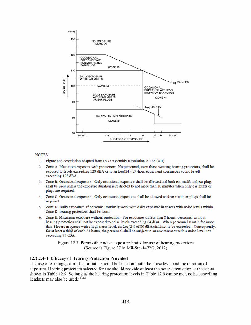
415
Figure 12.7 Permissible noise exposure limits for use of hearing protectors
(Source is Figure 37 in Mil-Std-1472G, 2012) 12.2.2.4-4 Efficacy of Hearing Protection Provided The use of earplugs, earmuffs, or both, should be based on both the noise level and the duration of exposure. Hearing protectors selected for use should provide at least the noise attenuation at the ear as shown in Table 12.9. So long as the hearing protection levels in Table 12.9 can be met, noise cancelling headsets may also be used.1472G
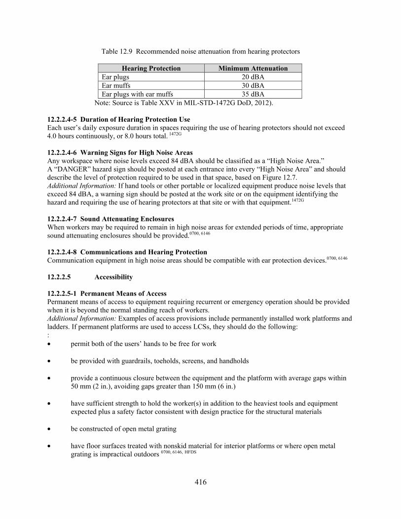
416
Table 12.9 Recommended noise attenuation from hearing protectors
Hearing Protection Minimum Attenuation Ear plugs 20 dBA Ear muffs 30 dBA Ear plugs with ear muffs 35 dBA
Note: Source is Table XXV in MIL-STD-1472G DoD, 2012). 12.2.2.4-5 Duration of Hearing Protection Use Each user’s daily exposure duration in spaces requiring the use of hearing protectors should not exceed 4.0 hours continuously, or 8.0 hours total. 1472G 12.2.2.4-6 Warning Signs for High Noise Areas Any workspace where noise levels exceed 84 dBA should be classified as a “High Noise Area.” A “DANGER” hazard sign should be posted at each entrance into every “High Noise Area” and should describe the level of protection required to be used in that space, based on Figure 12.7. Additional Information: If hand tools or other portable or localized equipment produce noise levels that exceed 84 dBA, a warning sign should be posted at the work site or on the equipment identifying the hazard and requiring the use of hearing protectors at that site or with that equipment.1472G 12.2.2.4-7 Sound Attenuating Enclosures When workers may be required to remain in high noise areas for extended periods of time, appropriate sound attenuating enclosures should be provided.0700, 6146 12.2.2.4-8 Communications and Hearing Protection Communication equipment in high noise areas should be compatible with ear protection devices.0700, 6146 12.2.2.5 Accessibility 12.2.2.5-1 Permanent Means of Access Permanent means of access to equipment requiring recurrent or emergency operation should be provided when it is beyond the normal standing reach of workers. Additional Information: Examples of access provisions include permanently installed work platforms and ladders. If permanent platforms are used to access LCSs, they should do the following: : • permit both of the users’ hands to be free for work
• be provided with guardrails, toeholds, screens, and handholds
• provide a continuous closure between the equipment and the platform with average gaps within
50 mm (2 in.), avoiding gaps greater than 150 mm (6 in.)
• have sufficient strength to hold the worker(s) in addition to the heaviest tools and equipment expected plus a safety factor consistent with design practice for the structural materials
• be constructed of open metal grating
• have floor surfaces treated with nonskid material for interior platforms or where open metal grating is impractical outdoors 0700, 6146, HFDS

417
12.2.2.5-2 Temporary Means of Access Temporary or movable access platforms to equipment should be available when the equipment is located beyond the normal standing reach of workers and permanent access provision is not feasible. Additional Information: If temporary platforms are used to access LCSs, they should have the following attributes: • be lightweight in their material and fully collapsible • if provided with wheels, have brakes and wheel locks 0700, 6146, HFDS 12.2.2.5-3 Appropriate Means of Access Catwalks, ladders, and other suitable means should be provided for workers to reach equipment. Additional Information: Workers should not be required to walk along pipes or to use components as “stepping stones” to reach equipment. If catwalks are used, the minimum floor width should be 460 mm (18 in.) to accommodate walking one foot in front of the other and carrying tools or equipment. 0700, 6146,
HFDS 12.2.2.5-4 Guardrails All open sides of personnel platforms should be equipped with guardrails, which have at least two rails (an intermediate rail and top rail). The open area of personnel platforms where work is to be done should be guarded without interfering with work tasks. Additional Information: Guardrail dimensions should be as follows: • top rail height at least 1.1 m (42 in.) • distance between the platform edge and the centerline of the railing not to exceed 65 mm (2.5 in.) • rail diameter between 37 mm (1.5 in.) and 75 mm (3 in.) HFDS 12.2.2.5-5 Toe Boards, Guard Screens, and Handholds Toe boards, guard screens, and handholds should be provided on platforms as needed. Additional Information: A toe board of 10 cm (4 in.) to 15 cm (6 in.) or a guard screen that extends from the floor base to the intermediate rail should be used to guard floor openings, to keep personnel, equipment, and tools from falling off the platform. Handholds should be furnished where needed to assist in climbing onto a platform, as aids in performing intended tasks from the platform, or where personnel must stabilize themselves because of high winds, ice, fog, or other hazards. HFDS 12.2.2.5-6 Sufficient Clearance Sufficient clearance should be provided near equipment in contaminated or high-temperature areas to allow workers easy access despite the use of protective garments and associated gear. Additional Information: A minimum of 0.4 square meters (4.0 square feet) per person should be provided for personnel, their tools, and equipment (including personal protective clothing), as well as free space for the movements and activities required to perform required tasks. 0700, 6146, 1472G 12.2.2.5-7 Impediments to Access Structural elements should not impede access to equipment needing to be operated. Additional Information: Structural elements added to the plant (e.g., seismic reinforcements) should not restrict access to equipment.0700, 6146 12.2.2.5-8 Access Assist Features Features to assist users to perform their tasks safely and efficiently should be incorporated into the LCS when required.
418
Additional Information: Auxiliary hooks, holders, lights, and outlets should be provided at the LCS as needed.1472G 12.2.2.5-9 Visual Inspection. Items requiring visual inspection (hydraulic reservoirs, gauges, digital displays or computer monitors) should be located so that users can see them without removing panels or other components, unless the panels are specifically for protection against the weather.1472G 12.2.2.6 Vibration 12.2.2.6-1 Building Vibration Building-induced whole-body vibration should not produce discomfort or annoyance in building users. Additional Information: Vibration levels that can produce discomfort or annoyance may interfere with task performance. When humans are exposed to whole-body vibration from buildings, the Wm frequency weighting should be used over the frequency range 1 Hz to 80 Hz, as specified in ISO 2631-2 (2003). Whole-body vibrations should not cause adverse health effects to users, especially low-back pain, digestive disorders, fatigue, or general discomfort. The following applies to whole-body vibration: • The daily exposure limit value (ELV), adjusted for an 8-hour reference period, should be
1.15 m/s2. Whole body vibration above this ELV should not be permitted. • The daily exposure action value (EAV), adjusted to an 8-hour reference period, should be
0.5 m/s2. Whole-body vibration above this EAV and below the ELV defined above should result in engineering controls and administrative actions to bring the user whole-body vibration exposure to below the EAV. Whole-body vibration below the EAV requires no action.
• The assessment of the level of exposure to vibration is based on the calculation of daily exposure,
expressed as equivalent continuous acceleration over an 8-hour period, calculated as the highest (rms) value, or the highest vibration dose value of the frequency-weighted accelerations, determined on three orthogonal axes in accordance with ISO 2631-1(1997).
Hand-arm vibrations should not cause adverse health effects to users, especially symptoms of the Hand-Arm Vibration Syndrome. NIOSH 83-110 (1983) has more information concerning this syndrome. Note the following for hand-arm vibration:
• The daily ELV, adjusted for an 8-hour reference period, should be 5 m/s2. Hand-arm vibration above this ELV should not be permitted.
• The daily EAV, adjusted to an 8-reference period, should be 2.5 m/s2. Hand-arm vibration above this EAV and below the ELV defined above, should result in engineering controls and administrative actions to bring the user hand-arm vibration exposure to below the EAV. Hand-arm vibration below the EAV requires no action.
• The assessment of the level of exposure to hand-arm vibration is based on the calculation of the daily exposure value adjusted to an 8-hour reference period, expressed as the square root of the sum of the squares (rms total value) of the frequency-weighted acceleration values, determined on the orthogonal axes as defined in ISO 5349-1(2001). 1472G
12.2.2.6-2 Reducing Vibration Steps should be taken to reduce vibration at its source.

419
Additional Information: The preferred approach for reducing vibration is to isolate it with machine mountings.0700, 5680 12.2.2.6-3 Limiting Transmission of Vibration Steps should be taken to limit the transmission of vibrations to workers. Additional Information: Workers can be isolated from vibration by means of shock-mounted, energy-absorbing platforms. If vibration-limiting gloves are to be used to isolate workers from hand-arm vibrations, these gloves should conform to ISO 10819 (2013).0700, 5680 12.2.2.6-4 Reducing the Effects of Vibration User interfaces should be designed to reduce the disruptive effects of vibration. Additional Information: Modifications that minimize the effects of vibration on task performance include installing larger dials that can be read despite vibration or providing a means for workers to stabilize their limbs.0700, 5680 12.2.2.6-5 Limiting Exposure to Vibration Steps should be taken to protect workers from excessive vibration. Additional Information: Administrative controls should limit the amount of time that workers are exposed to high levels of vibration. These controls should primarily address effects on comfort and worker safety. 0700, 5680 12.2.2.7 Other Environmental Considerations 12.2.2.7 -1 Adverse Environments The design of LCSs should consider adverse environmental factors of precipitation, sunlight (solar load), and dusty conditions.1472

420

421
13 MAINTAINABILITY OF DIGITAL SYSTEMS
Maintainability of Digital Systems Characterization The installation of digital equipment in nuclear power plant systems may range from replacing individual subsystems and components to completely replacing entire systems (i.e., a system based entirely on digital technology may supersede an analog monitoring system). Rather than replacing the entire system, a control system consisting of sensors, processors, controls, displays, and equipment actuators may have its analog processors upgraded with digital processors. When installing a digital processor, it may be necessary to install additional signal converters to translate the analog signals into digital format for the new processor and then translate the digital output of the processor back into analog format for the rest of the system. Thus, much of the plant system may retain its original analog design, resulting in a hybrid of digital and analog components. Digital systems may be described in terms of progressively smaller units (i.e., a unit of equipment may be defined as an assemblage of items that includes modules, components, and parts that are packaged together into a single hardware package). A module is defined as an assemblage of two or more interconnected parts or components that comprise a single physical entity with a specific function. A module may be a printed circuit board or a smaller unit containing individual components that plugs into a printed circuit board. A component is defined as a subdivision of a unit of equipment that the maintainer can treat as an object but that can be further separated into parts. A mounting board, together with its mounted parts, is an example of a component. A part is an object that cannot normally be broken down further without destroying its designated use; fuses, transistors, resistors, capacitors, and integrated circuit “chips” are examples of parts. When maintaining a digital system, maintenance personnel inspect, test, and service these units of equipment, modules, components, and parts. Important characteristics for maintenance personnel include instrument cabinets and racks, equipment packaging, fuses and circuit breakers, labeling and marking, adjustment controls, test points, and service points. They are described below, along with the test equipment used during maintenance. General This section provides guidance for the review of general maintainability considerations, such as minimizing maintenance demands; supporting the operator role in maintenance; and protecting personnel, equipment, and components from hazards. Section 13.1 provides review guidelines for these general considerations. Instrument Cabinets and Racks Instrument cabinets and racks are enclosures that hold modules, components, and parts. They typically have access doors or removable panels that allow access to their contents. The layout of these enclosures affects visual and physical access. Visibility is also affected by the presence of lighting as either permanent or temporary (e.g., handheld) fixtures. Other considerations include the amount of electrical wiring and protective features at the enclosure. Section 13.2 provides review guidelines. Equipment Packaging This refers to the way that modules, components, and parts are arranged within the enclosure. Section 13.3 provides review guidelines. Three packaging considerations are modularization, layout, and mounting.

422
Modularization This is a design strategy for enhancing maintainability by dividing a unit of equipment into individual modules. Four methods for organizing modules are logical flow packaging, circuit packaging, component packaging, and printed circuit boards. In logical flow packaging, circuits, parts, and components are arranged in correspondence with their functional relationships. In circuit packaging, all parts of a single circuit or logically related group of parts, and only that circuit or group, are placed in a separate module. In component packaging, similar parts or components are located together; for example, all the fuses or all the relays might be grouped together. With printed circuit boards, parts are mounted on a single integrated circuit board. Section 13.3.2 provides review guidelines. Layout This refers to the arrangement of modules relative to each other. Important considerations include their accessibility (e.g., consistency of orientation, spacing, and avoidance of stacking) and their grouping (e.g., by maintenance task). Section 13.3.3 provides review guidelines. Mounting This refers to the ways in which modules, components, and parts are attached. Considerations include the use of hinged mountings, rests, stands, and connectors, and their effects on mounting errors, equipment damage, and accessibility. Section 13.3.4 provides review guidelines. Fuses and Circuit Breakers These devices protect equipment from changes in electrical current. Considerations include their locations within equipment, indications of open circuits, protection of workers and circuits, and indication of rating. Section 13.4 provides review guidelines. Labeling and Marking This refers to the use of labels and demarcations to identify units of equipment, modules, components, and parts. Considerations include their placement, legibility, and durability. Section 13.5 provides review guidelines. Adjustment Controls Personnel use adjustment controls to affect the operation of equipment, such as by setting the value at which the equipment will operate. These controls may be external (e.g., mounted on maintenance panels) or internal (e.g., test and relay switches located on printed circuit boards). Section 13.6 provides review guidelines. Test Points and Service Points Test points are locations on equipment where test equipment can be connected. Some are specially designed to receive test equipment, such as ports for voltmeters and multipin connectors for automatic test equipment (ATE). Others include electrical connectors and terminals where test probes may be used to measure voltages or current. Considerations include location, arrangement, marking, and accessibility. Service points are locations on equipment where personnel perform routine maintenance tasks such as cleaning and changing components. For example, a digital system may contain a ventilation fan with an

423
air filter that must be periodically replaced. Considerations include location, arrangement, marking, and accessibility of service points. Section 13.7 provides review guidelines. Test Equipment Test equipment includes the diagnostic tools maintenance personnel use to assess the status of equipment and locate any faults. This equipment is used in periodic surveillance tests, periodic maintenance, and unscheduled maintenance caused by failures. Section 13.8 provides review guidelines. General Section 13.8.1 provides review guidelines on the general characteristics of test equipment. The discussion below describes specific topics for test equipment. Automatic Test Equipment ATE can check two or more signals in sequence without the intervention of a maintainer. They are usually programmable devices designed to exercise a set of functions of a particular portion of a digital system to detect faults. ATE is intended to relieve some of the burdens associated with manually testing digital systems. The tests may be focused at a high level, such as the operation of a subsystem, or at a low level, such as the operation of an individual component. Thousands of tests may be rapidly administered with minimal human intervention. For example, many integrated circuits, such as microprocessors, may require several hundred unique test patterns to verify that they are operating properly. ATE tests usually stop after the first out-of-tolerance signal is detected. Section 13.8.2.1 provides general review guidelines. Important specific considerations include the following: Testing intervals This refers to the way that the automatic test sequences are initiated (e.g., continuous, automatically, or manually). Section 13.8.2.2 provides review guidelines. Bypasses for plant and test equipment Automatic capabilities must sometimes be disabled (bypassed) to allow tests to be performed and then reinstated. Section 13.8.2.3 provides review guidelines. Failure indications These indications are used to determine the presence of a possible equipment failure and include the status of equipment redundancy, tolerance ranges, power, and circuit integrity. Section 13.8.2.4 provides review guidelines. Display of test results This refers to the way that test outcomes are presented. The go/no-go format provides results as one of two possible outcomes, the former indicating an acceptable condition and the latter indicating an unacceptable condition. This format may be used to indicate whether a given signal is in or out of tolerance. Collating test formats presents the results of two or more checks as a single display. For example, a “test passed” indication would occur only if all the relevant signals are in tolerance. Thus, it reduces the number of indications a maintainer must read, thereby reducing testing time. Other
424
considerations for displaying test results include using high- and low-value fault messages, ease of interpretation, identification of fault location, and identification of out-of-tolerance signals for collating test equipment. Section 13.8.2.5 provides review guidelines. Test Equipment Hardware Test equipment may exist as integral parts of plant equipment, such as built-in test capabilities, or as separate pieces of portable equipment. Portable test equipment may be as small as a handheld voltmeter or as large as an engineering workstation. For example, some portable ATE systems are essentially personal computers on wheels. They may be connected internally or externally to the plant equipment. For example, some test equipment has probes that are manually positioned on internal components of equipment to conduct tests. Other portable test equipment is connected to built-in test panels or ports located on the outside of the plant equipment. A built-in test panel may have multiple test ports, which may be annotated with block diagrams or overlays to identify the ports and their relationships to the equipment’s components. Section 13.8.3.1 provides general review guidelines, and Sections 13.8.3.2 and 13.8.3.3, respectively, provide guidelines specific to portable test equipment and built-in test panels. Bibliography Source Code Documents 6636 Stubler, W., Higgins, J., and Kramer, J. (2000) Maintainability of Digital Systems: Technical
Basis and Human Factors Review Guidance (NUREG/CR-6636). Washington, DC: U.S. Nuclear Regulatory Commission.
13.1 General 13.1.1 Minimizing Maintenance Demands 13.1.1-1 Minimizing Testing and Servicing Requirements for periodic or repetitive testing and servicing of components should be avoided where the possibility of human errors may affect safety. Additional Information: One way to reduce the need for testing and servicing is to use highly reliable components.6636 13.1.1-2 Equipment Independence for Maintenance Units of equipment should be as independent as is practical, such that maintenance of one unit has minimal effects on the other equipment. Additional Information: Functional, mechanical, electrical, and electronic independence can allow one unit to be maintained with minimal effects on other units. Units of equipment should correspond to the functional design of the equipment. The functional independence of each unit should be maximized while minimizing the interaction between them.6636 13.1.1-3 Minimize Maintenance Time Equipment should be designed to minimize the time required for maintenance if having the equipment out of service can affect safety. Additional Information: Minimizing the time required for maintenance can increase the equipment’s availability. One factor that can increase maintenance time is high cognitive demands associated with such activities as finding components and test or service points, tracing flows between components, and detecting and interpreting symptoms. A second factor is high physical demands, such as dexterity for disassembling and reassembling equipment; accessing internal components; and using connectors, test

425
points, and service points. Maintenance time may also be lengthened by factors that increase the likelihood of errors, such as inadequate feedback from plant or test equipment. In addition, factors that introduce delays or special logistic requirements, such as the need for special tools and test equipment, may prolong maintenance.6636 13.1.1-4 Ease of Fault Detection The design of equipment should facilitate rapid, positive fault detection and isolation of defective items.6636 13.1.1-5 Equipment Verification When feasible, equipment should permit verification of operational status before its installation and without the need for disassembly. Additional Information: For example, maintenance personnel should be able to verify that a module is in operating condition through inspections or tests, such as by attaching the equipment to a test device. These inspections and tests should not require the maintainer to disassemble the module.6636 13.1.1-6 Fault Detection Without Disassembly Equipment should permit fault detection and isolation without removing components, through the use of built-in tests, integrated diagnostics, or standard test equipment. Additional Information: Fault detection and isolation should unambiguously identify which component has failed.6636 13.1.1-7 Design for Repair by Module Replacement To reduce the likelihood of personnel errors in normal repairs conducted in difficult field environments, the design should support simple modular replacement in the field and repair in the shop. Additional Information: Repair activities, such as rewiring and replacing individual small components, may be more prone to errors when carried out in the field. Restricting field maintenance to replacing modules may reduce the likelihood of these errors.6636 13.1.1-8 Overall Accessibility Equipment that is to be maintained should be visually and physically accessible to the maintainer. Additional Information: Modules, components, parts, adjustment points, test points, cables, and connectors for all required maintenance tasks should be visually and physically accessible. Labels should be easily seen.6636 13.1.1-9 Standardized Designs for Construction Equipment used in assembling equipment, such as connectors, should be standardized as much as possible. Additional Information: Standardization reduces the need for maintainers to learn different skills for different designs and may reduce the likelihood of errors from using the wrong technique when disassembling and reassembling equipment.6636 13.1.1-10 Design Flexibility Equipment design should provide flexibility to allow future design modifications to be made without imposing high demands on personnel for installation and maintenance. Additional Information: Equipment should be designed to accommodate future modifications or replacement of equipment. Design flexibility includes functional and physical modularity to accommodate replacements and upgrades and spare physical capacity, such as in cabinets, panels, terminal strips, and wire ways, to provide room for larger or more numerous components. Extra electrical and processing capacity may also support the maintainability of future modifications.6636
426
13.1.1-11 Minimize Maintenance Equipment and Tools Units of equipment should be designed to minimize the numbers and types of auxiliary equipment and the tools required to service them. Additional Information: Tool requirements should be coordinated across the modules to minimize the number of different tools needed. For example, designers may design modules for the same type of screwdriver rather than requiring a slightly different one for each. The development of tool requirements requires an understanding of the maintenance tasks and the equipment’s characteristics. The goal of minimizing the number and types of tools should be addressed early in the equipment design process and then throughout design and development.6636 13.1.1-12 Use Common Test Equipment and Tools Whenever possible, systems and units of equipment should be designed so they can be maintained with common test equipment and tools. Additional Information: The need for specialty test equipment and tools should be avoided. Ideally, the tools required should be limited to those normally found in a maintainer’s tool kit. Modules should be designed so that they are replaceable by hand or with common tools.6636 13.1.1-13 Need for Special Skills Equipment should be designed to minimize the need for special skills on the part of the maintainers.6636 13.1.1-14 Need for Special Training Equipment should be designed to minimize the need to specially train the maintainers.6636 13.1.2 Continuous Operation and Online Maintenance 13.1.2-1 Local Indication of Redundant Equipment Status If equipment can automatically transfer operation between redundant units, local personnel who maintain that equipment should be informed of the transfer and the status of the redundant units. Additional Information: Some digital systems automatically transfer control between redundant processors when there is a failure. These redundant processors support online maintenance by allowing one processor to control the system while the others are being serviced. When maintenance is performed, local maintenance personnel should be alerted when an automatic transfer occurs and should be able to readily determine the status of the redundant processors and identify the one controlling the system. Local indications are preferable to control room indications so local personnel need not rely on workers for status information.6636 13.1.2-2 Degraded Operation Status and fault information should be provided to maintenance personnel and operators for equipment awaiting maintenance while operating in a degraded mode. Additional Information: Because of their importance in a system, some units of equipment may be designed to operate in a degraded mode after a partial failure while awaiting maintenance. Degraded operation and faults should be sensed and appropriate information identified, displayed, or transmitted to maintenance personnel and operators.6636

427
13.1.3 Supporting the Operator Role in Maintenance 13.1.3-1 Monitoring and Trending Equipment Degradation To support personnel awareness of impending equipment failures, monitoring and trending capabilities should be provided where possible to identify the degradation of equipment.6636 13.1.3-2 Operator Assistance in Testing and Repair Where practical, equipment should be designed to facilitate testing and repairs without requiring the assistance of the onshift operator. Additional Information: Maintenance activities should be designed so that they do not interrupt the operator at staffed control stations.6636 13.1.3-3 Operator Indication of Testing or Repair Activities The operators should be provided with an indication that testing or repairs are underway. Additional Information: Some testing and repairs may affect equipment or system operability or make it more susceptible to unusual events, such as spurious trips.6636 13.1.3-4 Indications for Equipment that Is Out of Service Means for indicating the status of equipment that is out of service should be provided. Additional Information: Administrative controls for managing these indications (i.e., for tagging-in and tagging-out equipment) also should be in effect.6636 13.1.4 Protecting Personnel from Hazards 13.1.4-1 Designing for Safety of Maintainers Equipment should not present hazards to maintainers as they follow maintenance procedures. Additional Information: A positive means (for example, disconnects or lockouts) should be designed into equipment to control hazardous conditions and increase safety. A hazardous condition is the presence of energy or a substance that is likely to cause death or injury by physical force, shock, radiation, explosion, flames, poison, corrosion, oxidation, irritation, or other debilitating features.6636 13.1.4-2 Covering Exposed Parts Protrusions and corners on equipment that maintainers might come into contact with should be covered with rubber or other appropriate materials. Additional Information: Protrusions and corners on equipment may injure the maintainers or cause them to make sudden motions that could damage plant equipment.6636 13.1.4-3 Energy Dissipation Before Maintenance Parts that retain hazardous levels of electrical potential or heat should be equipped with means to dissipate energy before maintenance. Additional Information: Heat sinks and electrical grounds can be used to dissipate energy before maintenance. Removing these hazards can reduce the risk of personnel injury. It may also reduce the risk of damage to plant equipment that could result from sudden personnel movements after touching hot or electrically charged surfaces.6636 13.1.4-4 Protecting Maintainers from Heat and Electrical Shock Equipment or parts that retain hazardous levels of heat or electrical potential during maintenance should be located where maintainers will not touch them during their work, or they should be shielded. Additional Information: For example, high-current switching devices should be shielded to prevent maintainers from coming into contact with them. Internal controls, such as switches and adjustment controls, should be located away from hazardous high-voltage sources with which the maintainers may

428
make contact while operating the controls. Shocks and burns received from equipment may injure maintenance workers or cause them to make sudden motions resulting in damage to equipment. This concern is particularly important for parts that retain energy after external energy sources have been removed or turned off.6636 13.1.4-5 Avoidance of Hazards for Adjustment Controls, Test Points, and Service Points Adjustment controls and test and service points should be located away from hazards. Additional Information: Adjustment controls and test and service points should not be located close to dangerous voltages, moving machinery, or other hazards, since contact with these hazards may injure maintenance workers or cause them to damage plant equipment by their sudden motion. They should be separated by more than a hand’s width, 114 millimeters (mm) (4.5 inches (in.), from the nearest hazard. If a hazardous location cannot be avoided, the control, test point, or service point should be appropriately labeled, shielded, and guarded.6636 13.1.5 Protecting Equipment and Components from Hazards 13.1.5-1 Protecting Equipment from Hazards Equipment should be protected from potential exterior hazards resulting from personnel actions. Additional Information: Protection may be provided by the design and location of equipment or by protective barriers or enclosures. Hazards resulting from personnel actions include physical forces, contact with contaminants (such as oil), other fluids, dirt, and contact with static electricity.6636 13.1.5-2 Avoiding Damage to Protruding Parts Irregular protrusions on a unit of equipment should be easily removed to prevent damage by personnel during installation and maintenance. Additional Information: An electrical cable is an example of an irregular protrusion.6636 13.1.5-3 Avoiding Damage When Opening and Closing Equipment The parts and wiring of a module should be located and arranged so that personnel do not damage them when opening and closing the module or the unit of equipment of which they are part.6636 13.1.5-4 Avoiding Damage When Maintaining Internal Components Parts that are susceptible to damage by personnel should be located or shielded so that they will not be damaged during maintenance.6636 13.2 Instrument Cabinets and Racks 13.2-1 Instrument Racks Instrument racks should support maintenance and testing by providing adequate physical and visual access to their contents. Additional Information: Instrument racks provide a location for mounting instruments and wiring.6636 13.2-2 Cabinet Lighting Cabinets requiring maintenance inside the enclosure should have permanent lighting. Additional Information: Permanently installed lighting should be an aid to personnel in diagnostics, repairs, and troubleshooting. Using hand-held lights may pose hazards for personnel or cause damage to equipment.6636 13.2-3 Minimizing Field-Run Wiring The amount of field-run wiring should be minimized to avoid errors in identifying and connecting wires. Additional Information: The amount of wiring carried out in the field may be reduced by using

429
multiconnector connections and preassembled wiring harnesses. Connectors may have features preventing problems such as improper indexing, electrical shorts, and inadvertent contacts.6636 13.2-4 Protective Electrical Grounds for Cabinets A protective ground should be provided. Additional Information: All cabinets where the operating voltage is greater than 50 volts should have a protective ground. Protective power grounds should be routed separately from signal grounds. Inadequate electrical grounding may cause electrical shocks to plant personnel, resulting in injury or sudden motion that may damage plant equipment.6636 13.3 Equipment Packaging 13.3.1 General 13.3.1-1 Organized by Maintenance Specialty Parts and modules should be packaged, laid out, and mounted so that maintenance performed by one maintenance specialist does not require removing or handling equipment or components maintained by another specialist. Additional Information: Reducing the number of maintenance specialties involved with each part or module can simplify the process, reduce the likelihood of errors and delays because of communication difficulties between specialists, and reduce the time that equipment is out of service.6636 13.3.2 Modularization 13.3.2.1 General 13.3.2.1-1 Modularization Units of equipment should be divided into as many modules as are practical and feasible to support personnel performance during maintenance. Additional Information: Dividing a unit of equipment into a number of separate modules has several advantages, including making it easier to (1) locate and isolate malfunctions, (2) reach, remove, and maintain components, (3) handle the equipment for installation and repair, and (4) allocate maintenance functions and responsibilities among personnel with different skills.6636 13.3.2.1-2 Physical and Functional Interchangeability If modules are physically interchangeable, they should also be functionally interchangeable to avoid errors in installing the wrong module. Additional Information: Functionally interchangeable units of equipment perform the same function. Physically interchangeable units of equipment can fit into the same mounting position or fixture. If two units of equipment are interchangeable functionally, they should also be interchangeable physically. However, if they are not interchangeable functionally, they should not be interchangeable physically. Units of equipment having the same form and function should be interchangeable throughout a system and related systems.6636 13.3.2.1-3 Distinguishing Noninterchangeable Modules The appearance of noninterchangeable modules should be distinguishable, and the difference should be apparent when the module is in its installed position. Additional Information: Interchangeable units of equipment should be clearly identifiable and easily distinguishable from units that are similar but not interchangeable. Identification methods might be physical (such as size, shape, and mounting provisions) or visual (such as color coding and labeling).6636

430
13.3.2.1-4 Replacement of Failed Components Equipment should be designed so that components that fail frequently can be easily replaced. Additional Information: Lamps and fuses are examples of parts that fail more frequently. If a module has parts that are significantly less reliable than the remaining ones, the unreliable parts should be accessible without removing the module.6636 13.3.2.1-5 Maintenance in Installed Location When possible, modules should be designed so that they can be maintained in their installed position, without requiring disconnection, disassembly, or removal of other modules.6636 13.3.2.1-6 Removal and Testing Modules should be designed to permit testing when they are removed from their installed position. Additional Information: Personnel should not be required to reinstall a module into the system to determine whether it has failed. Other system characteristics also may mask faults in the module. Testing the module directly may avoid these problems.6636 13.3.2.1-7 Installation and Testing Each module should allow separate installation and functional testing before the complete system is integrated. Additional Information: The design should allow maintenance personnel to test and confirm that the installed module is functioning properly before the complete system is installed.6636 13.3.2.1-8 Installation and Calibration Modules should require little or no calibration immediately after installation.6636 13.3.2.1-9 Interconnectivity The number of inputs and outputs associated with a module should be minimized, where possible, to reduce the likelihood of errors in installing connections or testing multiple inputs and outputs.6636 13.3.2.1-10 Modularization Method The modularization of digital equipment should be based on a systematic method that can be readily understood by maintenance personnel. Additional Information: Modularization, dividing a unit of equipment into individual modules, is a design strategy for enhancing maintainability. The following lists modularization methods that were recommended for the commercial aviation industry, in order of preference: (1) logical flow packaging, (2) circuit packaging, and (3) component packaging. In logical flow packaging, circuits, parts, and components are packaged and arranged in correspondence with their functional relationships. In circuit packaging, all parts of a single circuit or logically related group of parts, and only that circuit or group, are placed in a separate module. In component packaging, similar parts or components are located together; for example, all the fuses or all the relays might be grouped together.6636 13.3.2.2 Logical Flow Packaging 13.3.2.2-1 Isolating Module Faults by Single Input-Output Checks When logical flow packaging is used to modularize digital equipment, a module should be designed so that only single input and output checks are necessary to isolate a fault in it.6636 13.3.2.2-2 Indication of Unidirectional Signal Flow When logical flow packaging is used to modularize digital equipment, the unidirectional signal flow within a module should be clearly indicated.6636

431
13.3.2.3 Circuit Packaging 13.3.2.3-1 Locating Parts in a Single Module When circuit packaging is used to modularize digital equipment, all parts of a given circuit or group of logically related parts should be located in a single module to help personnel find and test them. Additional Information: Testing and diagnosis may be difficult if related parts are distributed in different locations.6636 13.3.2.3-2 Only One Circuit or Group of Related Parts Per Module When circuit packaging is used to modularize digital equipment, a module should contain only one circuit or group of related parts to support testing and diagnosis. Additional Information: If a module contains multiple circuits or groups, then testing and diagnosis may be difficult (e.g., personnel may access the wrong parts when testing a circuit).6636 13.3.2.3-3 Packaging a Circuit as a Single Terminal-Board or Plug-In Module When circuit packaging is used to modularize digital equipment, the circuit should be packaged as a single terminal board or plug-in module, when possible, to support its testing and installation. Additional Information: Providing a single board or module reduces the number of parts that must be handled and reduces the likelihood of errors during handling, testing, and installation.6636 13.3.2.3-4 Grouping Circuits to Minimize the Crossing of Signals When circuit packaging is used to modularize digital equipment, circuits should be grouped to minimize crisscrossing of signals among modules. Additional Information: When circuits are improperly grouped, crossed signals may result from handling errors. Furthermore, crossed signals can complicate fault detection and diagnosis.6636 13.3.2.4 Component Packaging 13.3.2.4-1 Grouping Components with Similar Replacement Schedule When using component packaging to modularize digital equipment, similar parts that are likely to require replacement at approximately the same time should be grouped together.6636 13.3.2.4-2 Grouping Components with Similar Servicing Requirements When component packaging is used to modularize digital equipment, components requiring the same maintenance work should be grouped together (e.g., test points or components requiring a particular cleaning method).6636 13.3.2.5 Printed Circuit Boards 13.3.2.5-1 Design for Removal and Replacement Printed circuit boards should be designed and mounted for ease of removal and the elimination of errors during replacement. Additional Information: The physical design should make it impossible to install a printed circuit board upside down or backwards.6636 13.3.2.5-2 Plug-In Printed Circuit Boards Plug-in printed circuit boards should be structurally rigid and easy to remove and replace, providing finger access and gripping aids, if necessary.6636 13.3.2.5-3 Feedback When Installing Plug-In Printed Circuit Boards The maintainer should receive feedback when plug-in printed circuit boards are securely connected.
432
Additional Information: For example, a tactile or audible “click” may indicate that the printed circuit board has been properly inserted.6636 13.3.2.5-4 Identification of Printed Circuit Boards and Parts Printed circuit boards should be marked to identify the board and the parts mounted on it. Additional Information: MIL-STD-130J (DoD, 1997) has guidance for identifying printed circuit boards. MIL-STD-454 (DoD, 1985) Requirement 67, gives guidance on providing references for parts mounted on a printed circuit board.6636 13.3.3 Layout 13.3.3.1 Module Accessibility 13.3.3.1-1 No Interference from Other Parts Modules should be laid out so that all parts can be removed and replaced without interference from or removal of other parts. Additional Information: Units that may have to be removed for maintenance should be situated so they can be moved without interference in straight horizontal or vertical paths.6636 13.3.3.1-2 No Stacking of Parts To support accessibility, parts that make up a module should be mounted in an orderly, flat, two-dimensional array and should not be stacked one on top of another. Additional Information: An orderly, two-dimensional array allows parts to be accessed individually. Stacking is not recommended because some parts must be removed to provide access to the parts located below or behind them.6636 13.3.3.1-3 Consistent Orientation If a module has more than one part of the same type that must be inserted in a particular orientation, all such parts should be oriented in the same direction. Additional Information: For example, a set of connectors should be installed with the same orientation.6636 13.3.3.1-4 Spacing of Parts The parts that make up a module should be spaced and oriented so that required tools can be used without difficulty. Additional Information: For example, the spaces between parts should accommodate the use of test probes or soldering irons. Parts should be oriented so they can be reached with the required tools.6636 13.3.3.1-5 Separation of Parts and Wiring on Printed Circuit Boards To support accessibility for testing parts on printed circuit boards, all parts should be mounted on one side of the board and all wiring, including printed circuits, should be located on the other side. Additional Information: Damage to circuit boards during testing can be avoided by making parts accessible.6636 13.3.3.1-6 Spacing of Terminals Terminals to which wires are to be soldered should be far enough apart so that work on one terminal does not damage neighboring terminals or nearby parts.6636
433
13.3.3.1-7 Indicator Lights If a module has indicator lights, it should be possible to change them from the front panel, without opening or removing the module.6636 13.3.3.1-8 Shutoff Switches If the module contains emergency shutoff switches, they should be positioned within easy reach, and they should be located or guarded to prevent inadvertent operation.6636 13.3.3.1-9 Test, Adjustment, and Connection Points Test points, adjustment points, and cable and line connectors should be located where the maintainer can see them easily and operate on them without interference.6636 13.3.3.2 Grouping 13.3.3.2-1 Grouping Maintenance Display Devices All maintenance display devices relevant to a particular task should be grouped together and located where they can easily be seen.6636 13.3.3.2-2 Separate Maintenance and Operational Display Devices If a unit of equipment contains both maintenance and operational display devices, the two types of devices should be separated.6636 13.3.3.2-3 Separate Maintenance and Operational Displays in a Display Network If a display device contains displays for both maintenance and operations personnel, then the maintenance displays should have a separate location in the display network. Additional Information: Maintenance displays should not be located within the same part of the display network as operational displays because their presence may interfere with the ability of operators to promptly access operational displays. Displays used by maintenance personnel generally should not be accessible by operational personnel unless operators need them to perform their tasks. Access to maintenance displays should be protected by passwords, key locks, or similar measures.6636 13.3.4 Mounting 13.3.4-1 Support for Hinged Mounting If a module is mounted on hinges, supports should hold the module in the “out” or “open” position. Additional Information: Parts and wiring should be positioned so that they are not damaged during opening and closing; see Guideline 13.1.5-3.6636 13.3.4-2 Rests and Stands If a module contains parts that might be damaged when it is moved into position for maintenance, it should include rests or stands that are integral with the construction of the module to protect those parts.6636 13.3.4-3 Preventing Mounting Errors by Physical Design Modules should be designed so that it is physically impossible to mount them incorrectly. Additional Information: Incorrect mounting includes reversal, mismating, and misaligning. Measures to prevent incorrect mounting include (1) incorporating keys or other aligning devices, (2) using asymmetrical mounting brackets, and (3) having asymmetrical mounting holes.6636 13.3.4-4 Controls Modules should be mounted so that it is unnecessary to disconnect controls that may be needed for

434
maintenance.6636 13.3.4-5 Front Access Replaceable modules should be accessible through the front of the equipment, rather than the back, if the panel or console is not used by operators. Additional Information: Convenient access can reduce the likelihood of damage during installation, replacement, and testing. However, if maintenance is to be performed on line, then access to the module should not interfere with plant operations.6636 13.3.4-6 Orientation of Modules within Cases If a module has a case, the proper orientation of the module within its case should be obvious, preferably through the physical design of the case, rather than through labeling.6636 13.3.4-7 Connectors Electrical connections between modules should be simple and should minimize the demands for manual dexterity. Additional Information: A plug-in connector requires minimal dexterity. Connectors requiring greater dexterity may be used when there are special requirements, such as holding power or sealing.6636 13.3.4-8 Standard Connectors Connectors should be standardized as much as possible. Additional Information: Standardization reduces the need for different techniques for using each connector and may reduce the likelihood of errors from using the wrong technique.6636 13.4 Fuses and Circuit Breakers 13.4-1 Location of Fuses and Circuit Breakers Fuses and circuit breakers should be grouped in a minimum number of centralized, readily accessible locations for removal, replacement, and resetting. Additional Information: Fuses should be located so they can be replaced without removing any other components.6636 13.4-2 Verification of an Open Circuit An indication should be given when a fuse or circuit breaker has opened a circuit.6636 13.4-3 Individual Fused Units Fuses or circuit breakers should be provided so that each unit of a system is separately fused and adequately protected from harmful variations in voltages that personnel may cause.6636 13.4-4 Worker Safety Fuse installations should be designed so that only the neutral (“cold”) terminal of the fuse can be touched. Additional Information: Shocks received from equipment may injure maintenance workers or cause them to make sudden movements, which can damage equipment.6636 13.4-5 Safeguarding the Circuit Fuses should be provided that safeguard the circuit if the wrong switch or jack position is used.6636 13.4-6 Easily Removed Fuse Holders Fuse holder cups or caps should be easily removed by hand. Additional Information: Fuse holder cups or caps should be of the quick-disconnect type rather than the screw-in type; they should be knurled and large enough to be handled easily. Replacing fuses should not

435
require special tools unless they are needed for safety.6636 13.4-7 Identifying Fuses and Circuit Breakers Fuses and circuit breakers should be permanently labeled or marked. Additional Information: The labeling or marking should be legible in the anticipated ambient work conditions. Both fuses and fuse holders should be labeled.6636 13.4-8 Indicating Fuse Ratings A fuse’s rating should be indicated on the fuse and adjacent to the fuse holder. Additional Information: The rating should be in whole numbers, common fractions, such as ½, or whole numbers and common fractions, such as 2½.6636 13.4-9 Identifying Affected Circuits The area of equipment served by a fuse or circuit breaker should be identified.6636 13.5 Labeling and Marking 13.5-1 Standard Labels Equipment labels should be standardized as much as possible.6636 13.5-2 Information Content of Labels and Markings for Modules Modules should be labeled or marked to supply information needed by maintainers. Additional Information: Labels or markings used for modules should do the following: • outline and identify functional groups of parts • identify each part by name or symbol • indicate direction of current or signal flow to aid troubleshooting • identify the value and tolerance level of parts or test points, if applicable • identify each part by a unique serial identification number 6636 13.5-3 Visibility of Labels and Markings Labels and markings on parts or in cabinets should be placed so that the maintainer can see them without having to move or remove anything. Additional Information: The maintainer should not be required to remove parts or move wires to read labels and markings.6636 13.5-4 Consistent Placement of Labels and Markings Labels and markings should be consistently placed in relation to the parts to which they refer. Additional Information: This placement may be on, or immediately adjacent to, the part.6636 13.5-5 Luminescent Labels If labels must be read under very low ambient light, they may be marked in phosphorescent colors.6636 13.5-6 Electrical Parts Small electrical parts that are attached to mounting boards, such as resistors and capacitors, should be labeled or marked on the mounting boards. Additional Information: Labeling and marking should appear on the mounting boards if the parts are too small to accommodate legible, salient labels and markings.6636

436
13.5-7 Identification of Parts Parts should be identified with labels or markings. Additional Information: Labels or markings should be placed either on the parts themselves or on the chassis or adjacent board. The following are types of parts that should be labeled or marked: • all parts identified by designations in drawings, schematics, and parts descriptions of the module • all wires, sockets, plugs, receptacles, and similar parts designated in wiring diagrams of the
module • all replaceable mechanical parts • all semifixed electrical items, such as fuses and ferrule-clipped resistors • items having critical polarity or impedance ratings 6636 13.5-8 Identification of Terminals on Terminal Strips or Blocks The terminals of terminal strips or blocks should be labeled on the strip or block, or on the chassis, adjacent to the terminals.6636 13.5-9 Identification of Terminals on Parts When parts have terminals (e.g., transformers, relays, and capacitors), each terminal should be identified by an adjacent label.6636 13.5-10 Identification of Parts Accessible from Both Sides Receptacles that are accessible from both sides of a board or panel should be identified on both sides. Additional Information: Some boards and panels contain receptacles that allow parts to be accessed from either side.6636 13.5-11 Durability of Markings Markings should be durable enough to last the life of the equipment.6636 13.5-12 Marking Stacked Parts If parts or modules are stacked, marking should permit identification of the individual parts or modules. Additional Information: Stacking of parts or modules is not recommended (see Guideline 13.3.3.1-2).6636 13.5-13 Marking Enclosed or Shielded Parts, Modules, Test Points, and Service Points Enclosed or shielded parts, modules, test points, and service points should be marked both outside the enclosure or shield and inside it.6636 13.5-14 Hazard Warnings If there is any hazard from a part or module, a warning or caution label should be provided on it, on the case or cover, or both.6636 13.5-15 Labeling Symmetrical Parts Parts that are symmetrical should be labeled or marked to indicate their proper orientation for mounting.6636

437
13.5-16 Insertion Holes If a module has holes through which parts must be aligned and then inserted, labels showing the proper orientation of the part should be placed adjacent to the holes. Additional Information: Tubes and connectors are examples of parts that may be inserted through holes in modules.6636 13.5-17 Auxiliary Information for Parts Parts to which auxiliary information applies should be labeled with that information. Additional Information: Examples of auxiliary information include values and tolerances of resistors and capacitors. This information should be in an easily readable form.6636 13.6 Adjustment Controls 13.6-1 Misalignment Controls and displays should be designed to prevent misalignment that might be caused by vibration, service use, or accidental contact.6636 13.6-2 Controls and Feedback Each adjustment control should provide feedback. Additional Information: This feedback might be visual, audible, or tactile.6636 13.6-3 Simultaneous Access to Controls and Displays Maintainers should have simultaneous access to an adjustment control and its associated display or other source of feedback. Additional Information: Maintainers should be able to observe the effects of adjustments as they are made.6636 13.6-4 Differentiating Maintenance Controls from Operational Controls Maintenance and operational controls should be clearly differentiated.6636 13.6-5 Location of Maintenance and Operational Controls The maintenance and operational controls should not appear on the same panel if maintenance and operation of a unit of equipment are performed by different sets of people. Additional Information: If maintenance and operational controls must appear on the same panel, the maintenance controls should be grouped and separated from the operational controls. If appropriate, the maintenance controls might also be guarded with removable covers so as not to interfere with the operator’s performance.6636 13.6-6 Independence of Adjustment Controls Where possible and practical, the adjustment of one control should be independent of the adjustments of others.6636 13.6-7 Sequential Adjustments If the adjustment of one control affects the adjustment of another, the controls should be arranged in sequential order and labeled or marked to indicate the order of adjustment.6636 13.6-8 Functionally Related Adjustments If a single control is used to affect multiple variables, then the user interface should be designed to prevent mode errors. Additional Information: Mode errors occur when the user performs an action that is appropriate for one mode when a different mode is in effect. Four design strategies for preventing mode errors are eliminating

438
modes, making modes distinct, providing different inputs for different modes, and coordinating inputs across modes. Eliminating modes prevents mode errors by eliminating the conditions under which they occur (i.e., if there are no modes, there can be no mode errors). Making modes distinct deals with the problem through feedback. By saliently indicating the currently active mode, operators are more likely to be aware of it and less likely to provide an incompatible input. Providing different inputs for different modes addresses the problem by ensuring that the same input is not valid in more than one mode. Thus, if the operator provides an input while in the wrong mode, the system will not accept it. Coordinating inputs across modes ensures that a command producing a benign effect in one mode does not produce a severely negative effect in another mode.6636 13.6-9 Degree of Adjustment Controls should accommodate the degree of adjustment required; that is, gross adjustment, fine adjustment, or both.6636 13.6-10 Mechanical Stops Adjustment controls intended to have a limited range of motion should have mechanical stops. Additional Information: These stops should be able to withstand a force or torque 100 times greater than the resistance to movement within the range of adjustment.6636 13.6-11 Previous Settings If a task requires that a maintainer be able to quickly return a control to its previous setting, the control should have a scale and pointer, or equivalent.6636 13.6-12 Preventing Inadvertent Adjustment Adjustment controls should be located and mounted so that they cannot be adjusted inadvertently.6636 13.6-13 Critical or Sensitive Adjustments Critical or sensitive adjustments should incorporate features, such as locking devices, to prevent inadvertent or accidental adjustment. Additional Information: If a locking device is used, its operation should not change the adjustment setting.6636 13.6-14 Hand or Arm Support If an adjustment control or the maintainer will be subject to vibration during adjustment, a suitable hand or arm support should be provided. Additional Information: Vibrations can cause the maintainer to overshoot or undershoot the desired adjustment value.6636 13.7 Test Points and Service Points 13.7.1 General 13.7.1-1 Ease of Servicing Equipment should be designed so that it can be serviced in its installed position to prevent errors associated with disassembling and reassembling it.6636 13.7.1-2 Appropriate Use of Test Points Test points should be provided on units of equipment as required to support personnel in checking, adjusting, and troubleshooting it. Additional Information: Strategically placed test points make signals available to maintenance personnel. Test points may not be required if the equipment has self-checking capabilities.6636
439
13.7.1-3 Single Adjustment Control Per Test Point A test point should not have more than one associated adjustment control.6636 13.7.1-4 Ground Points Special grounding points should be provided, as needed, in locations in which surfaces have poor electrical grounding characteristics. Additional Information: Maintainers may have difficulty if only painted surfaces are available for ground connections.6636 13.7.2 Location, Arrangement, and Marking 13.7.2-1 Test Points for Units of Equipment Where possible, each input to and output from a unit of equipment should have test points to support testing and diagnosis of faults.6636 13.7.2-2 Tracing Signals Test points should be provided to permit the systematic tracing of signals and voltages through a unit of equipment to support fault detection and diagnosis. Additional Information: These test points allow a maintainer to determine the point at which signals or voltages in a malfunctioning unit are out of tolerance.6636 13.7.2-3 Test and Service Point Accessibility All test and service points should be visible and physically accessible to the maintainer for checking and troubleshooting. Additional Information: Recommended minimum clearances are 19 mm (0.75 in.) when only finger control is required and 75 mm (3 in.) when using gloves.6636 13.7.2-4 Proximity of Controls, Displays, and Test Points Test points should be located in physical and visual proximity to the controls and displays used to make the adjustments. Additional Information: The adjustment control should provide a signal detectable at the test point that clearly indicates when the correct adjustment has been made.6636 13.7.2-5 Proximity of Controls, Displays, and Service Points Service points should be located in physical and visual proximity to the controls and displays used when adjusting them.6636 13.7.2-6 Test and Service Point Location Test and service points should be provided, designed, and located in accordance with their frequency of use and with any time limits on maintenance. Additional Information: Isolated test or service points should be avoided because they are likely to be overlooked or neglected.6636 13.7.2-7 Compatibility of Test and Service Points Test and service points should be designed for compatibility with checking, troubleshooting, and servicing procedures, and with test and service equipment.6636

440
13.7.2-8 Distinctive Connections Each type of test or service equipment should have distinctively different connectors or fittings to minimize the likelihood of error. Additional Information: Providing visually distinct connectors or fittings for different types of test and service equipment may reduce the likelihood that a maintainer will mistake one type for another. Physical differences between different types of connectors and fittings may prevent a maintainer from connecting the wrong piece of test or service equipment, if it is physically incompatible with the test or service connector or fitting.6636 13.7.2-9 Distinguishable Marking Test and service points should be designed and marked so that they are easily distinguishable from each other. Additional Information: If color coding is used, the color of test points should clearly differ from that of service points.6636 13.7.3 Accessibility 13.7.3-1 Access Openings for Test Equipment Access openings necessary to connect test equipment should accommodate maintainers, equipment, and required tools.6636 13.7.3-2 Test Probe Guides Suitable guides for test probes should be provided when test points are located internally within an enclosure. Additional Information: When a maintainer inserts a test probe through an opening in an enclosure, a guide can help the test probe make contact with the internal test point.6636 13.8 Test Equipment 13.8.1 General 13.8.1-1 Built-In Test Capabilities All test capabilities for a unit of equipment should be built in, to the extent feasible, to reduce the likelihood of testing errors. Additional Information: Built-in test capabilities can avoid errors associated with disassembling plant equipment or connecting test equipment. The handling involved with removing and transporting a component to a test site may introduce new faults in sensitive equipment. Built-in diagnostics and testing features allow equipment to be tested in place. If it is not practical or possible to incorporate all test equipment, then test jacks may be provided to allow internal components to be tested by external test devices without disassembling the plant equipment.6636 13.8.1-2 Appropriate Use of Alarms If critical equipment is not regularly monitored, an alarm should be provided to indicate malfunctions or conditions that would cause personnel injury or equipment damage. Additional Information: The alarm may be auditory, visual, or both. If an auditory alarm would be overly intrusive or disruptive, the alarm should be visual. A combination of auditory and visual alarms should be provided when the ambient illumination may impair the maintainer’s ability to see the latter. A high degree of ambient illumination may cause visual glare, affecting the detection of light-emitting alarms. A low degree of ambient illumination may interfere with the ability to detect and read alarms on light-reflecting displays.6636
441
13.8.1-3 Accuracy of Test Equipment The accuracy of test equipment should be consistent with testing requirements. Additional Information: In general, the accuracy of test equipment should exceed that of the equipment being tested.6636 13.8.1-4 Instructions Clearly written and easily understandable operating instructions for the test equipment should be available to the maintainer.6636 13.8.1-5 Labels Equipment labels should identify all items the maintainer must be able to recognize, read, or use. Additional Information: The test equipment should be labeled to identify the equipment, its purpose, and any precautions that should be observed in its use. There should be adequate warnings wherever potential hazards exist.6636 13.8.1-6 Minimizing Errors The test equipment should be designed to minimize errors by the maintainer. Additional Information: If possible, it should provide messages to support the detection of errors.6636 13.8.1-7 Minimizing Hazards When possible, fail-safe features should be incorporated in test equipment to minimize dangers to maintainers or equipment. Additional Information: For example, test equipment should have fuses or other protective features to prevent damage or injury if a wrong switch or jack position is used.6636 13.8.2 Automatic Test Equipment 13.8.2.1 General 13.8.2.1-1 Automated Aids Fault isolation, inspection, and checkout tasks should be automated to the extent practical to support personnel performance. Additional Information: These tasks are prone to human error. At a minimum, self-check diagnostic tests should operate automatically on powering up plant equipment and at the operator’s request.6636 13.8.2.1-2 Online Diagnostics Computer systems should have online diagnostic capabilities, if the detection and diagnosis of computer faults is required. Additional Information: The detection and diagnosis of computer faults can be complicated and difficult. Online diagnostic capabilities, which allow computer systems to be tested while they are running, can be effective for finding faults because they test the computer under operating conditions. Online diagnostic capabilities should be able to check both hardware and software when the symptoms may appear similar to maintenance personnel. Checks may be used to detect software malfunctions and unauthorized changes in software.6636 13.8.2.2 Test Intervals 13.8.2.2-1 Continuous Online Self-Testing The capability for continuous online self-testing should be provided when practicable to support prompt detection of faults. Additional Information: Continuous online self-testing allows tests to be performed with minimal

442
involvement by personnel and can reduce the amount of time between the occurrence and the detection of a fault. Tests may include, but should not be limited to, random access memory and read-only memory failure checks, arithmetic processing unit failure checks, data link buffer checks, and central processing unit reset of watchdog timers. For safety-related systems, testing features should be designed to reduce the complexity of safety-related software logic and data structures.6636 13.8.2.2-2 Periodic Testing The capability for periodic functional testing that is manually initiated but executed automatically should be provided when personnel require control of the test intervals. Additional Information: Automatic execution of tests is preferred when human errors may cause transients.6636 13.8.2.3 Bypasses for Plant and Test Equipment 13.8.2.3-1 Automatic Bypass When a test is initiated manually, the correct bypasses required for testing should be established automatically, and the operators should be aware of all of them. Additional Information: When a component is tested, it may be necessary to bypass other systems or functions associated with the component to prevent them from being affected. The operators should be made aware of these bypasses.6636 13.8.2.3-2 Indicators for Test and Bypass Status Local indication of pass or fail for test and bypass status should be provided for periodic functional tests. Additional Information: Indicators should be provided at the local cabinet to quickly show the pass or fail status for the test and the status of bypasses.6636 13.8.2.3-3 Removal of Automatic Bypass When a periodic functional test sequence is completed, all bypasses established to allow the test to be performed should be automatically removed, to relieve the operator of this task. Additional Information: Indications should be given to allow operators to verify the status of the bypasses and that the system has been properly reconfigured for normal operation. Removal of automatic bypasses may reduce the potential for errors that could unintentionally activate equipment.6636 13.8.2.3-4 Bypassed Diagnosis Routines To support the diagnosis of faults, diagnosis routines that are bypassed during maintenance should be run again before equipment is put back in service. Additional Information: When a component is serviced, it may be necessary to disable some automatic diagnosis routines. Running the routines before the equipment is put back into service ensures that they are available. It also supports the detection of any faults that may have occurred during testing. Failure to restore the diagnostic routines may increase the time required to detect future faults.6636 13.8.2.4 Failure Indications 13.8.2.4-1 Loss of Redundancy For redundant designs, when a system, as a piece of equipment, module, or component, becomes inoperable, an indication of alarm signaling the loss of redundancy should be provided to the users immediately. Additional Information: The loss of redundancy should be continuously displayed until the redundant system, equipment, module, or component becomes operable again.6636

443
13.8.2.4-2 Overload Indications Overload indications should be provided for equipment subject to this condition. Additional Information: This indication should be provided even if the equipment continues to operate when overloaded.6636 13.8.2.4-3 Identification of Acceptable Ranges When practical, the ranges for which test values are within acceptable limits should be indicated on built-in test equipment. Additional Information: For example, an acceptable reading for a meter or an acceptable wave shape for an oscilloscope should be coded for each position of the rotary switch of the built-in test equipment.6636 13.8.2.4-4 Out-of-Range Indicators If equipment has failed or is not operating within acceptable limits, an indication should be provided.6636 13.8.2.4-5 Power Failure Indicators If a power failure occurs, an indication should be given. Additional Information: A power-on indicator that extinguishes with loss of power should be provided. If a fuse or circuit breaker has opened a circuit, there should be an indication.6636 13.8.2.5 Display of Test Results 13.8.2.5-1 Inclusion of Fault Messages Fault messages should only be shown if they add value to the maintenance process. Additional Information: The presence of unnecessary fault messages can reduce the effectiveness of maintenance personnel by increasing the workload associated with locating and using messages that support diagnosis and repair. The flexibility of computer-based technologies and the needs of secondary users of the maintenance system can result in the inclusion of variables and capabilities that do not support the performance of primary users. Limiting messages to those that are valuable to the maintenance process can help personnel use the ATE effectively. The status of some variables can be determined by direct observation without using ATE. The appropriateness of including these variables in a test device should be based on consideration of their effects on maintenance performance. Thus, the burdens associated with viewing additional variables should be weighed against the potential benefits of having fault indications consolidated in a test device.6636 13.8.2.5-2 Direct Interpretation of Test Results Messages provided by test equipment should require a minimum amount of interpretation. Additional Information: Messages provided by test equipment should not use abbreviations, contractions, or numeric codes. Conversion tables should not be needed to determine whether the equipment is within tolerances. Test equipment that requires maintenance personnel to read codes and then look up the code on a table to obtain an explanation are susceptible to errors in reading, recording, and looking up the codes.6636 13.8.2.5-3 Identification of Failure Location Test features should identify the location of the detected failure to the lowest replaceable module. Additional Information: Test equipment should also inform maintenance personnel of the types of actions required to return the equipment to service. For example, even though the failure exists in component A, the corrective action may require that components B, C, and D be replaced at the same time.6636 13.8.2.5-4 Identification of Out-of-Tolerance Signals on Collating Test Equipment If equipment fails a test performed by collating test equipment, the test equipment should indicate which signal(s) are out of tolerance.

444
Additional Information: Collating test equipment presents the results of two or more checks as a single display; for example, a “test passed” light illuminates only if all of the relevant signals are within tolerance. Collating test equipment reduces the number of displays the maintainer must read, thereby reducing testing time. However, it should identify the out-of-tolerance signal(s) rather than merely indicating that the equipment failed the test.6636 13.8.3 Test Equipment Hardware 13.8.3.1 General 13.8.3.1-1 Requirements for Test Equipment and Bench Mockups Test equipment and bench mockups should be treated like any other equipment with respect to the human factors engineering design requirements for units, covers, cases, cables, connectors, test points, displays, and controls. Additional Information: Test equipment and bench mockups should be designed to be consistent with the capabilities of users and to prevent personal injury.6636 13.8.3.1-2 Selector Switches Selector switches should be used rather than many individual plug-in connections, as long as the effects of switching do not degrade the desired information. Additional Information: When connecting test equipment to particular circuits, selector switches can be used more quickly than many individual plug-in connections and can reduce the likelihood of incorrect or faulty connections.6636 13.8.3.1-3 Minimizing Test Equipment Accessories The number and types of test equipment accessories, such as connectors and test cables, should be minimized.6636 13.8.3.1-4 Minimizing Test Equipment Controls, Displays, and Modes Test equipment should be simple to operate and have a minimum number of controls, displays, and modes. Additional Information: Controls and displayed information should be organized to reduce the amount of mental effort required to find, access, and use them. Test equipment should not have many individual control and display devices such that the maintainer must coordinate to operate it. However, their number should not be reduced to such a degree that many control and display modes are introduced, which can create opportunities for mode errors.6636 13.8.3.1-5 Reducing the Number and Complexity of Steps The number and complexity of steps required to operate the test equipment should be minimized. Additional Information: The number and complexity of steps may be reduced by grouping controls, such as by sequence or criticality, or by automating certain operations.6636 13.8.3.1-6 Individual Operation Test equipment should be designed for operation by one person, if practical.6636 13.8.3.1-7 Calibration Check Test equipment should be easily calibrated or equipped with a simple check to indicate whether or not it is out of calibration or malfunctioning. Additional Information: A go/no-go indicator may provide a simple check of the status of the test equipment.6636
445
13.8.3.1-8 Avoid Temporary Equipment Configurations for Testing The use of temporary equipment configurations for periodic, functional testing of equipment should be avoided. Additional Information: Temporary equipment configurations include added jumpers, lifting leads, and swapping cables. Built-in test features may alleviate problems experienced in nuclear power plants that result from designs with poor testability.6636
13.8.3.2 Portable Test Equipment 13.8.3.2-1 Portable Diagnostic Tools Portable diagnostic equipment should be provided to aid in fault isolation when built-in equipment is not practical. Additional Information: Built-in equipment is generally preferable to portable equipment when it eliminates activities prone to error, such as disassembling plant equipment or connecting portable test equipment.6636 13.8.3.2-2 Ease of Connection Portable test equipment should allow rapid and error-free connection to the equipment being tested. Additional Information: The use of a single, multiprong connector can avoid errors that could occur if multiple wires were connected individually.6636 13.8.3.2-3 Calibration Information If maintenance personnel are required to verify that test equipment has been calibrated, then this information should be available to them. Additional Information: A calibration record may be attached to the equipment with this information.6636 13.8.3.3 Built-In Test Panel 13.8.3.3-1 Test Point Connections Test points should permit the connection of the appropriate test equipment, such as voltage meters. Additional Information: The purpose of a built-in test panel is to allow external test devices to assess internal components without disassembling the plant equipment.6636 13.8.3.3-2 Test Point Indication Labeling and Demarcation Test points should be clearly indicated on the test panel. Additional Information: For example, test points might be arranged within a miniature block diagram of the system with each block representing components or units of equipment. As another example, an overlay may be provided to indicate the test points that should be checked, the order in which they should be checked, and the tolerance limits for signals.6636

446
447
14 DEGRADED HSI AND I&C CONDITIONS
Degraded HSI and I&C Conditions Characterization Modern instrumentation and control (I&C) systems provide a great deal of functionality that is vital to plant performance and safety. The I&C system’s human-system interface (HSI) and plant personnel do the following: • sense basic parameters and statuses
• monitor the plant’s processes, performance, and various barriers that prevent release of
radioactive material
• adjust operations as needed
• respond to transients, accidents, and other failures Modern digital systems provide added functionality when compared with analog systems and can perform sophisticated monitoring, diagnostic, and prognostic functions. They also are able to use control algorithms that are more advanced than those used in nuclear power plants to date. Employing more advanced techniques will provide more intricate and complex control of plant systems and processes than those currently used. Digital I&C systems also support new forms of automation that make greater use of interactions with personnel. Although plant designers use a diversity of I&C architectures, they provide the same high-level functions. The U.S. Department of Energy’s I&C roadmap for advanced nuclear power plant programs describes I&C subsystems that provide these high-level functions (Dudenhoeffer et al., 2006): • Sensor subsystem—Nearly every plant process uses some form of physical measurement taken by
sensors that detect parameters in the plant, such as neutron flux, temperatures, pressures, flow, valve positions, electrical current levels, and radiation levels. Some new nuclear-energy production technologies employ new, different types of sensors and instruments to measure physical processes. In some reactor designs, they include electronic sensors with imbedded software that are required to work in high-temperature environments and measure and analyze process parameters quite different from those in today’s operating plants.
• Monitoring subsystem—These subsystems monitor the signals and other information produced by
sensors and evaluate that information to determine whether and what type of response is needed. They can contain sophisticated diagnostic and prognostic functions. Diagnostics refers to techniques for identifying and determining the causes of deviations or faults in the plant’s systems or processes. Prognostics refers to methods for using sensor data to estimate the rate of physical degradation and the remaining useful life of systems, predicting time to failure, and applying this information to more effectively control processes.
• Automation and control subsystem—Digital control systems offer the ability to apply more
advanced control algorithms than those presently used in U.S. nuclear power plants that rely primarily on single-input, single-output, classical control schemes to automate individual control loops. Advanced control schemes include matrix techniques for optimal control, nonlinear control methods, fuzzy logic, neural networks, adaptive control (a control that modifies its behavior based on plant dynamics), expert systems, state-based control schemes, and other schemes
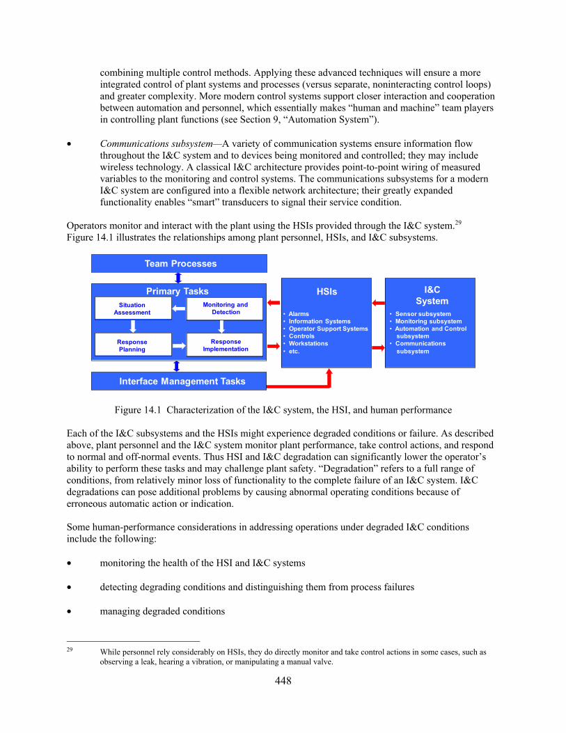
448
combining multiple control methods. Applying these advanced techniques will ensure a more integrated control of plant systems and processes (versus separate, noninteracting control loops) and greater complexity. More modern control systems support closer interaction and cooperation between automation and personnel, which essentially makes “human and machine” team players in controlling plant functions (see Section 9, “Automation System”).
• Communications subsystem—A variety of communication systems ensure information flow
throughout the I&C system and to devices being monitored and controlled; they may include wireless technology. A classical I&C architecture provides point-to-point wiring of measured variables to the monitoring and control systems. The communications subsystems for a modern I&C system are configured into a flexible network architecture; their greatly expanded functionality enables “smart” transducers to signal their service condition.
Operators monitor and interact with the plant using the HSIs provided through the I&C system.29 Figure 14.1 illustrates the relationships among plant personnel, HSIs, and I&C subsystems.
Figure 14.1 Characterization of the I&C system, the HSI, and human performance Each of the I&C subsystems and the HSIs might experience degraded conditions or failure. As described above, plant personnel and the I&C system monitor plant performance, take control actions, and respond to normal and off-normal events. Thus HSI and I&C degradation can significantly lower the operator’s ability to perform these tasks and may challenge plant safety. “Degradation” refers to a full range of conditions, from relatively minor loss of functionality to the complete failure of an I&C system. I&C degradations can pose additional problems by causing abnormal operating conditions because of erroneous automatic action or indication. Some human-performance considerations in addressing operations under degraded I&C conditions include the following: • monitoring the health of the HSI and I&C systems
• detecting degrading conditions and distinguishing them from process failures
• managing degraded conditions
29 While personnel rely considerably on HSIs, they do directly monitor and take control actions in some cases, such as
observing a leak, hearing a vibration, or manipulating a manual valve.
Monitoring and Detection
SituationAssessment
ResponsePlanning
ResponseImplementation
Primary Tasks I&CSystem
• Sensor subsystem• Monitoring subsystem • Automation and Control
subsystem • Communications
subsystem
Team Processes
HSIs
• Alarms • Information Systems• Operator Support Systems• Controls• Workstations• etc.
Interface Management Tasks

449
• transitioning to backup systems when degraded conditions result in a loss of needed functionality,
such as in a failure The review guidance in this section focuses on the HSI characteristics that support these activities. The guidance is organized into the following sections: 14.1 HSIs for Monitoring I&C System Conditions 14.2 HSI Response to I&C System Changes 14.3 Information Source and Quality 14.4 Backup of HSI and I&C Failures
Appendix B.5 contains additional information about degraded HSIs and I&C systems. Appendix B to NUREG-0700 contains guidance for selected HSI topics. Reviewers can address these considerations on a case-by-case basis during specific reviews. The process guidance for degraded HSIs and I&C systems is organized into the following sections:
B.5.1 Operating Experience Review B.5.2 Task Analysis B.5.3 Treatment of Important Human Actions B.5.4 Human-System Interface Design B.5.5 Training Program Development B.5.6 Human Factors Verification and Validation Bibliography Source Code Documents 0700 U.S. Nuclear Regulatory Commission (1981). Guidance for Detailed Control Room Design
Reviews (NUREG-0700, Rev. 0). Washington, DC: U.S. Nuclear Regulatory Commission. 0835 U.S. Nuclear Regulatory Commission (1981b). Human Factors Acceptance Criteria for the
Safety Parameter Display System (NUREG-0835). Washington, DC: U.S. Nuclear Regulatory Commission.
1342 Lapinsky, G., Eckenrode, R., Goodman, P., and Correia, R. (1989). A Status Report Regarding
Industry Implementation of Safety Parameter Display System (NUREG-1342). Washington, DC: U.S. Nuclear Regulatory Commission.
6633 O’Hara, J., Higgins, J., and Kramer, J. (2000). Advanced Information Systems: Technical Basis
and Human Factors Review Guidance (NUREG/CR-6633). Washington, DC: U.S. Nuclear Regulatory Commission.
6634 O’Hara, J., Higgins, J., and Kramer, J. (2000) Computer-Based Procedure Systems: Technical
Basis and Human Factors Review Guidance (NUREG/CR-6634). Washington, DC: U.S. Nuclear Regulatory Commission.
67651 O’Hara, J. and Thomas, T. (2014). Development of NUREG-0700 Review Guidance for Degraded
Human-System Interface, Instrumentation, and Control Conditions (BNL Technical Report No. 67651). Upton, NY: Brookhaven National Laboratory.

450
Other References Dudenhoeffer, D., Hallbert, B., Miller, D., Quinn, T., Arndt, S., Bond, L., O’Hara, J., Garcia, H., Holcomb, D., Wood, R., and Naser, J. (2007). Technology Roadmap: Instrumentation, Control, and Human Machine Interface to Support DOE Advanced Nuclear Power Plant Programs (INL/EXT-06-11862). Washington, DC: U.S. Department of Energy. O’Hara J., Gunther, W., and Martinez-Guridi, G. (2010). The Effects of Degraded Digital Instrumentation and Control Systems on Human-System Interfaces and Operator Performance (BNL Tech Report No. 91047-2010). Upton, NY: Brookhaven National Laboratory. 14.1 HSIs for Monitoring I&C System Conditions 14.1-1 Overall Representation of the I&C System The HSI should provide a representation of the I&C system and its subsystems. Additional Information: The representation of the I&C system and its subsystems should be sufficiently detailed to enable operators to monitor its performance and detect HSI and I&C degradations, especially those affecting important human actions, as identified in NUREG-0711, “Human Factors Engineering Program Review Model,” Revision 3, issued November 2012. 67651 14.1-2 Hierarchic Access to Information Information should be presented using a hierarchic approach enabling users to quickly and easily determine the overall status of I&C systems and subsystems from top-level displays and to access more detailed information on lower level displays. Additional Information: Information hierarchies provide operators with a means to monitor the I&C system’s status at a brief glance and then to access progressively more detailed information to support their situation assessment and troubleshooting. The displays should contain navigation aids to enable users to quickly and easily move from high-level displays to low-level displays in the hierarchy (see NUREG-0700, Section 2.5.1, “Display Selection and Navigation”). 67651 14.1-3 Indicate Important Status and Performance Parameters The HSI should provide information about each I&C subsystem’s status and performance parameters. Additional Information: The intent of this guideline is to give operators knowledge about how well the HSI and I&C system are performing. If the HSI includes status and performance information for HSI and I&C subsystems, operators can monitor that performance. Comparing current performance with typical performance will support operators in detecting changes in the system. Personnel can be supported when I&C systems have continuous online self-testing and monitoring and trending capabilities to promptly identify degradations (see Guidelines 13.8.2.2-1 and 13.1.3-1 for additional information). 67651 14.1-4 Indication of Proper HSI Operation A display feature should be provided to indicate to the user that the HSIs are operating properly. Additional Information: For example, a display of calendar date and time can be used to indicate whether a computer display is functioning. A built-in testing feature may be used to assess operability of the system.0700
14.1-5 User-Requested Status Check The HSI should allow users to request an HSI or I&C system check. Additional Information: If users suspect that the HSIs or I&C system may not be working properly, requesting a status check can help resolve the concern. This is especially important for checking automation systems. 67651

451
14.2 HSI Response to I&C System Changes 14.2-1 Notification of Important Changes The HSIs should notify users to important changes in I&C system status, performance, and degrading conditions. Additional Information: Alerts should be graded based on the need for the operator’s action (e.g., if immediate action is needed, an alarm should be used). Indications are especially important for systems that fail without producing immediately noticeable changes in the plant’s behavior. In the context of this guideline, in a degraded condition, the I&C system is still carrying out its function, but its performance is not optimal. The communication subsystem provides an example. If the subsystem is performing, but time delays exist slowing down information display and response to the operator’s control inputs, operators should be alerted to the condition. Additional examples of degraded conditions that should be indicated include: • loss of redundancy (until the redundant system, equipment, module, or component becomes
operable again)
• overload indications (even if the equipment continues to operate) when overloaded
• out-of-range indicators
• power failure indicators (i.e., a power-on indicator that extinguishes with loss of power should be provided and if a fuse or circuit breaker has opened a circuit, there should be an indication)
• automation degradation (automation should degrade smoothly when situations change sufficiently to render its performance unreliable and should communicate such circumstances to personnel in a timely way to enable them to become more engaged in the responsibilities of the automation)
Depending on the nature of the alert, alerts should be routed to the most appropriated destinations (e.g., control room operators or maintenance personnel). (See Section 4.1.4, “Alarm Routing,” for additional information.) 67651 14.2-2 Indication of Information Inaccuracy Information system failures (caused by sensors, instruments, and components) should result in distinct display changes, which directly indicate that depicted information is not valid. Additional Information: The information system should be designed so that failures in instrumentation are readily recognized by operators. When panel instruments, such as meters, fail or become inoperative, the failure should be apparent to the user (e.g., through offscale indication). This may be more difficult to determine in complex graphics; thus, they should be carefully evaluated.6633 14.2-3 Alarm to HSI and I&C System Failure The HSI should alarm when a failure of the HSI and I&C subsystem occurs. Additional Information: In the context of this guideline, when the I&C system’s (or subsystem’s) performance has degraded to the point where it cannot meet its function, it is considered failed. When the failure reflects an HFE-significant I&C degradation, the operator should receive an alarm. As with all alarms, operators should be given timely warning so they can implement compensatory actions or backup procedures. 67651 14.2-4 Information on Failure Cause The HSI should support users in determining the cause(s) of degraded conditions and failures.

452
Additional Information: Automation, for example, can mask failures and degraded conditions in other plant systems when it compensates for them. This can lead to the operator’s loss of situation awareness and becomes problematic when the situation reaches a point at which automation no longer compensates and personnel have to take over. 67651 14.3 Information Source and Validity 14.3-1 Identify Information Source The HSI should support operators in distinguishing between displayed information that is user entered, directly sensed, derived, or synthetic. Additional Information: The effect of degraded I&C conditions can be more difficult to understand when displayed information comes from different sources. Four types of information can be displayed on plant HSIs: user entered, directly sensed, derived, and synthetic. Some information displayed in the HSI can be entered by users. Directly-sensed information is derived from a sensor measurement (e.g., the flow out of a tank based on a flow sensor in the output pipe). Derived information is displayed information that could be based directly on sensor measurement but instead is derived from the measurements of other sensors. For example, the flow into a tank might not be directly sensed but can be assessed from a change in level over time. Synthetic information represents higher order information about a plant that cannot be sensed directly but is computed mathematically from data gained from sensors (e.g., rate of change, mass balance). The overall status of a safety function may represent synthetic information based on a computation from the function’s key safety parameters. Any such data used in these calculations from degraded or faulty sensors may propagate to the synthetic variable and distort its meaning. One approach to minimize this concern is to distinguish between these sources in a display, so operators can readily determine whether information is directly sensed or is derived from sensors. 67651 14.3-2 Data Validation Data presented in the HSI should be validated in real time, where possible. Additional Information: The HSI should not give false indications of plant status; therefore, methods should be used for ensuring that data are reliably presented to the operators. One approach to minimizing the impact of a degraded sensor and monitoring system is to ensure the information displayed at the operator’s HSI is correct, and to code suspect information. Techniques such as range checks for failed instruments, signal validation, and analytical redundancy can be used to evaluate the correctness of information before displaying it. Range checks for failed instruments can ensure that failed instruments are identified and that they are not averaged with other, valid readings, possibly masking the failed instrument. Comparing and possible averaging of redundant instruments can improve the quality and reliability of data. Analytical redundancy refers to the comparison of measured sensor readings, through the use of mathematical models based upon known physical relationships among parameters, to determine whether there are inconsistencies in the values. For example, “reactor power,” “reactor coolant temperature rise through the reactor core,” and “reactor coolant flow rate” are interrelated parameters based upon the physical principles of heat transfer. A measured value for coolant flow should be consistent with the analytically calculated value for coolant flow derived from the corresponding measured values of reactor power and coolant temperature rise.0835, 1342, 67651 14.3-3 Invalid Data Variables that are subject to validation (e.g., checks for accuracy) should be identified and an indication should be provided when these data are invalid. Additional Information: When data fail to meet the specified criteria for validity and thus are suspected of being of poor quality, an indication of validation failure should be provided. 67651 14.3-4 Unvalidated Data When checks for accuracy could not be performed, the unvalidated status of the data should be clearly

453
indicated. Additional Information: When checks for accuracy cannot be performed (e.g., a processor or redundant sensors are not available), the data are unvalidated. (Unvalidated data may be determined to be either valid or invalid as a result of the data validation process.) Under some conditions, unvalidated data may be useful to trained users in determining both the safety status of the plant and whether human intervention is needed. Clear indications of the unvalidated status of the data should be provided so the user can exercise judgment in interpreting them. 67651 14.3-5 Display of Data Reliability and Validation The status of information should be displayed to the user with an appropriate quality indicator (e.g., valid, invalid, unvalidated, or numerical estimate). Additional Information: Operators should also have available (e.g., on a separate display page) the individual sensor readings, so they can pinpoint an indicated problem, if the validation fails.0835
14.4 Backup of HSI and I&C Failures 14.4-1 Backup System Availability Backup systems should be available for HSI and I&C failures. 67651, 6634
14.4-2 Support Failure Recovery and Transition to Backup Systems The HSI should support operators in determining the steps for failure recovery or backup actions, should recovery be impossible. Additional Information: When a failure of automation is detected, the HSI should provide displays and information that allow personnel to rapidly determine what actions they must take to respond to the failure. For example, a procedure might be developed describing the appropriate response to various HSI and I&C failures. As another example, the HSI for an automated process that fails to manual mode should alert personnel that manual control is now required and point to or directly display the actions or procedures necessary to carry out the required manual actions. 67651, 6634

454
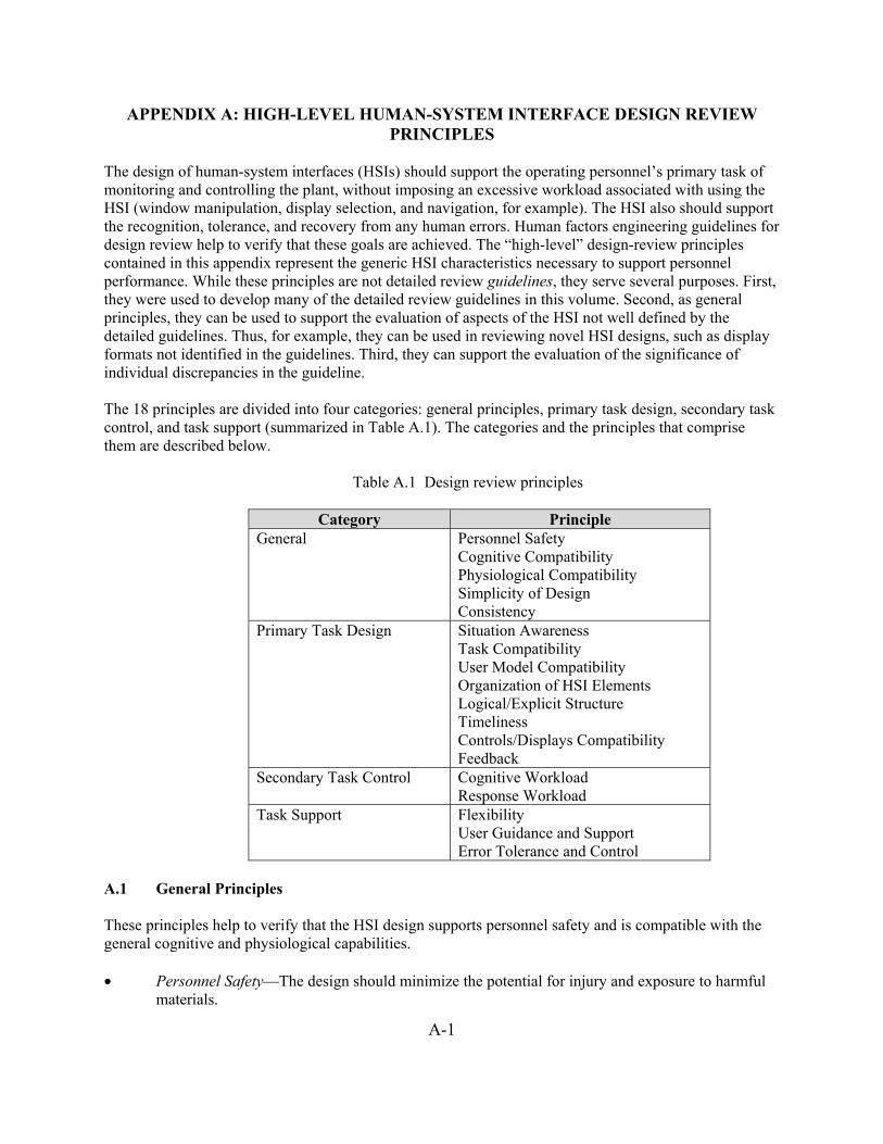
A-1
APPENDIX A: HIGH-LEVEL HUMAN-SYSTEM INTERFACE DESIGN REVIEW PRINCIPLES
The design of human-system interfaces (HSIs) should support the operating personnel’s primary task of monitoring and controlling the plant, without imposing an excessive workload associated with using the HSI (window manipulation, display selection, and navigation, for example). The HSI also should support the recognition, tolerance, and recovery from any human errors. Human factors engineering guidelines for design review help to verify that these goals are achieved. The “high-level” design-review principles contained in this appendix represent the generic HSI characteristics necessary to support personnel performance. While these principles are not detailed review guidelines, they serve several purposes. First, they were used to develop many of the detailed review guidelines in this volume. Second, as general principles, they can be used to support the evaluation of aspects of the HSI not well defined by the detailed guidelines. Thus, for example, they can be used in reviewing novel HSI designs, such as display formats not identified in the guidelines. Third, they can support the evaluation of the significance of individual discrepancies in the guideline. The 18 principles are divided into four categories: general principles, primary task design, secondary task control, and task support (summarized in Table A.1). The categories and the principles that comprise them are described below.
Table A.1 Design review principles
Category Principle General Personnel Safety
Cognitive Compatibility Physiological Compatibility Simplicity of Design Consistency
Primary Task Design Situation Awareness Task Compatibility User Model Compatibility Organization of HSI Elements Logical/Explicit Structure Timeliness Controls/Displays Compatibility Feedback
Secondary Task Control Cognitive Workload Response Workload
Task Support Flexibility User Guidance and Support Error Tolerance and Control
A.1 General Principles These principles help to verify that the HSI design supports personnel safety and is compatible with the general cognitive and physiological capabilities. • Personnel Safety—The design should minimize the potential for injury and exposure to harmful
materials.

A-2
• Cognitive Compatibility—The operator’s role should consist of purposeful and meaningful tasks
that enable personnel to maintain familiarity with the plant and support a workload level that is not so high as to negatively affect performance but is sufficient to maintain vigilance.
• Physiological Compatibility—The design of the interface should reflect consideration of human
physiological characteristics, including visual and auditory perception, biomechanics (reach and motion), characteristics of motor control, and anthropometry.
• Simplicity of Design—The HSI should represent the simplest design consistent with functional
and task requirements. • Consistency—There should be a high degree of consistency among the HSI, the procedures, and
the training systems. At the HSI, the way the system functions and appears to the operating crew always should be consistent, reflect a high degree of standardization, and be fully compatible with procedures and training.
A.2 Primary Task Design These principles support the operator’s primary task of process monitoring, decision making, and control to maintain safe operation. • Situation Awareness—The information presented to the users by the HSI should be correct,
rapidly recognized, and easily understood (e.g., “direct perception” or “status-at-a-glance” displays) and support the higher level goal of user awareness of the status of the system.
• Task Compatibility—The system should meet the requirements of users to perform their tasks
(including operation, safe shutdown, inspection, maintenance, and repair). Data should be presented in forms and formats appropriate to the task (including the need to access confirmatory data or raw data, in the case of higher level displays), and control options should encompass the range of potential actions. There should be no unnecessary information or control options.
• User Model Compatibility—All aspects of the system should be consistent with the users’ mental
models (understanding and expectations about how the system behaves as developed through training, use of procedures, and experience). All aspects of the system also should be consistent with established conventions (i.e., expressed in customary, commonplace, useful, and functional terms, rather than abstract, unusual, or arbitrary forms, or in forms requiring interpretation).
• Organization of HSI Elements—The organization of all aspects of the HSI (from the elements in
individual displays and individual workstations to the entire control room) should be based on user requirements and should reflect the general principles of organization by importance, frequency, and order of use. Critical safety-function information should be available to the entire operating crew in dedicated locations to facilitate its recognition and to minimize data search and response.
• Logical/Explicit Structure—All aspects of the system (formats, terminology, sequencing,
grouping, and operator’s decision-support aids) should reflect an obvious logic based on task requirements or some other nonarbitrary rationale. The relationship of each display, control, and data-processing aid to the overall task or function should be clear. The structure of the interface

A-3
and its associated navigation aids should make it easy for users to recognize where they are in the data space and should enable them to get rapid access to data not currently visible (e.g., on other display pages). The way the system works and is structured should be clear to the user.
• Timeliness—The system design should take into account users’ cognitive processing capabilities,
as well as process-related time constraints, to verify that tasks can be performed within the time required. Information flow rates and control performance requirements that are too fast or too slow could diminish performance.
• Controls/Displays Compatibility—Displays should be compatible with the data entry and control
requirements. • Feedback—The system should provide useful information on system status, permissible
operations, errors and error recovery, dangerous operations, and validity of data. A.3 Secondary Task Control These principles minimize secondary tasks (i.e., tasks that personnel perform when interacting with the HSI that are not directed to the primary task). Examples of secondary tasks include activities associated with managing the interface, such as navigation through displays, manipulating windows, and accessing data. Performing secondary tasks detracts from the crew’s primary tasks, so the demands of secondary tasks must be controlled. • Cognitive Workload—The information presented by the system should be rapidly recognized and
understood; therefore, the system should minimize requirements for making mental calculations or transformations and use of recall memory (recalling lengthy lists of codes, complex command strings, information from one display to another, or lengthy action sequences). Raw data should be processed and presented in directly usable form (although raw data should be accessible for confirmation).
• Response Workload—The system should require a minimum number of actions to accomplish a
task (e.g., single versus command keying, menu selection versus multiple command entry, single input mode (keyboard, mouse) versus mixed mode). In addition, the system should not require the entry of redundant data or the reentry of information already in the system, including information the system can generate from already resident data.
A.4 Task Support These principles address the characteristics of the HSI that support its use by personnel, such as providing (1) HSI flexibility so tasks can be accomplished in more than one way, (2) guidance for users, and (3) mitigation of errors.
• Flexibility—The system should give the user multiple means to carry out actions (and verify
automatic actions) and permit displays and controls to be formatted in a configuration most convenient for the task. However, flexibility should be limited to situations where it offers advantages in task performance (such as to accommodate different levels of user experience); it should not be provided for its own sake because there is a tradeoff with consistency and the imposition of interface management workload (which detracts from monitoring and operations tasks).

A-4
• User Guidance and Support—The system should provide an effective “help” function.
Informative, easy-to-use, and relevant guidance should be provided on line and off line to help the user understand and operate the system.
• Error Tolerance and Control—A fail-safe design should be provided wherever failure can
damage equipment, injure personnel, or inadvertently operate critical equipment. Therefore, the system should generally be designed such that a user error will not have serious consequences. The negative effects of errors should be controlled and minimized. The system should offer simple, comprehensible notification of the error and simple, effective methods for recovery.
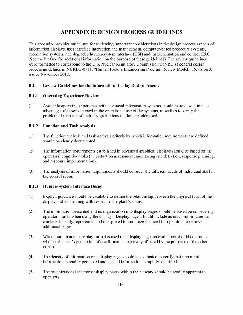
B-1
APPENDIX B: DESIGN PROCESS GUIDELINES This appendix provides guidelines for reviewing important considerations in the design process aspects of information displays, user interface interaction and management, computer-based procedure systems, automation systems, and degraded human-system interface (HSI) and instrumentation and control (I&C). (See the Preface for additional information on the purpose of these guidelines). The review guidelines were formatted to correspond to the U.S. Nuclear Regulatory Commission’s (NRC’s) general design process guidelines in NUREG-0711, “Human Factors Engineering Program Review Model,” Revision 3, issued November 2012. B.1 Review Guidelines for the Information Display Design Process B.1.1 Operating Experience Review (1) Available operating experience with advanced information systems should be reviewed to take
advantage of lessons learned in the operational use of the systems, as well as to verify that problematic aspects of their design implementation are addressed.
B.1.2 Function and Task Analysis (1) The function analysis and task analysis criteria by which information requirements are defined
should be clearly documented. (2) The information requirements established in advanced graphical displays should be based on the
operators’ cognitive tasks (i.e., situation assessment, monitoring and detection, response planning, and response implementation).
(3) The analysis of information requirements should consider the different needs of individual staff in
the control room. B.1.3 Human-System Interface Design (1) Explicit guidance should be available to define the relationship between the physical form of the
display and its meaning with respect to the plant’s status. (2) The information presented and its organization into display pages should be based on considering
operators’ tasks when using the displays. Display pages should include as much information as can be efficiently represented and interpreted to minimize the need for operators to retrieve additional pages.
(3) When more than one display format is used on a display page, an evaluation should determine
whether the user’s perception of one format is negatively affected by the presence of the other one(s).
(4) The density of information on a display page should be evaluated to verify that important
information is readily perceived and needed information is rapidly identified. (5) The organizational scheme of display pages within the network should be readily apparent to
operators.

B-2
(6) Access to displays within a network should be evaluated to verify rapid, efficient retrieval of
information needed to support operators’ tasks. (7) Unwanted effects of integrating a new, novel graphic representation into a conventional HSI
(other displays, other control room HSIs, and environmental considerations such as lighting levels) should be evaluated and minimized.
(8) The following aspects of information system design should be carefully analyzed and evaluated:
• Number of video display units (VDUs)—to verify that the display area is sufficient to
show the important information needed by operators without them having to perform extensive interface management.
• Interface management functions—to verify that the HSI features are easy to use and provide explicit interface management support.
• Flexibility of HSI and display features and functions—to verify that the flexibility of the system does not unduly burden operators, nor increase the chance of misunderstandings and errors.
(9) Methods should be specified for ensuring that plant modifications (such as changes in
instrumentation or systems) are incorporated into the display and do not introduce inconsistencies in how they correspond to plant situations, or lead to technical inaccuracies and, possibly, invalid displays.
(10) If display formats are developed for a generic plant design or as an “off-the-shelf” product, any
plant-specific inputs to display characteristics need to be analyzed to verify that the display correctly reflects the relationship between the changes in the display format and the changes in the specific plant it is intended to represent.
B.1.4 Training Program Development (1) The knowledge, skills, and abilities that the operators need to use and understand the information
system should be specified. (2) Operators should be trained on the relationship between the display form and the plant states it is
intended to represent, including failure modes and their effect on graphic representation. (3) Users should be trained in using the interface management features of the information system,
including navigation within and between displays, manipulation of onscreen features such as windows, and use of user-definable characteristics and features.
(4) Users should be trained to an acceptable level of proficiency with unfamiliar graphic displays
before using them in the control room to verify that operators are sufficiently familiar with them to correctly assess their meaning.

B-3
B.2 Review Guidelines for the User Interface Interaction and Management Design Process B.2.1 Function and Task Analysis (1) Analyses of function allocation should be performed for new or modified interface management
functions that are associated with important personnel actions. These analyses should consider the effects of new or changed interface management functions on crew situation awareness and workload. Opportunities to automate aspects of interface management to reduce its demands on personnel should be identified.
(2) Task analyses should identify requirements for managing multiple, concurrent tasks, especially
during high workload conditions, including factors that affect the pace of tasks, requirements for alternating concurrent tasks, demands for detecting changes and shifting attention, and resulting workload. Operator activities addressed by these analyses should include concurrent access to information and controls, keeping track of in-progress and suspended tasks, anticipating future demands, and coordinating and communicating with other personnel. These analyses should provide a basis for HSI characteristics, including: (1) the types of information and controls that should be presented together on display pages, (2) types of display pages that should be presented together in display networks, and (3) the number and placement of display devices (VDUs) in the HSI. These analyses should also provide a basis for the types of interactions between the users and the HSI that are to be supported by the HSI design.
(3) Task analyses should identify specific interface management skills that users will need for
managing multiple, concurrent tasks, especially during high-workload conditions. These analyses should assess the current skills and skill levels and determine any increment that will be required from formal and on-the-job training.
(4) If an HSI is modified, the task analyses should address strategies and skills used by personnel in
the existing HSI configuration to access and use information and controls. Strategies that users employ for modifying the HSI or adjusting it for particular tasks should be noted for possible inclusion in the HSI design goals. When user modifications and adjustments of the HSI are identified that represent weaknesses of the current design, these weaknesses should be corrected through the design goals for the upgrade. When they represent desirable dimensions of HSI flexibility that should be retained by the HSI upgrade, these desirable dimensions should be identified in the HSI design goals.
(5) Task analyses should identify requirements for multiple individuals to interact with shared
displays and controls. These analyses should provide a basis for HSI features that support crew interaction, including group-view displays and methods of human-system interaction that support the sharing of controls and displays. These analyses should also provide a basis for determining training requirements for the use of shared displays and controls.
(6) Task analyses should be conducted to assess the potential effects of interface management tasks
on the performance of primary (supervisory control) tasks. These analyses should address demands associated with use of the interface management features. These analyses should also address tasks associated with malfunctions of the HSI.

B-4
B.2.2 Human Reliability Analysis (1) Human reliability analyses (HRA) should be performed when the introduction of HSI
technologies are likely to change interface management demands associated with risk-important tasks to determine the potential impact on reliability. The scope of these human reliability analyses should address personnel actions resulting from the HSI technologies and their interactions with the rest of the plant. Consideration should be given to the effects that changes in the HSI may have on the existing plant HRA, including the following:
• whether the original HRA assumptions are valid for the upgraded design
• whether the human errors analyzed in the existing HRA are still relevant to the upgrade
• whether the probability of errors by plant personnel may change
• whether new errors not modeled by the existing HRA and probabilistic risk assessment
(PRA) may be introduced
• whether the consequences of errors established in the existing HRA may change B.2.3 Human-System Interface Design B.2.3.1 HSI Design Process Inputs (1) Design goals and requirements for interface management features should be derived from
analyses of user tasks. These analyses should address information and control capabilities required by users, requirements for managing multiple concurrent tasks, requirements for multiple individuals to interact with shared displays and controls, and backup information and control capabilities for coping with malfunctions of the HSI. If the HSI component or system will be installed as an upgrade to an existing HSI, then the design goals and requirements should also be derived from analyses of strategies and skills used by personnel in the existing HSI configuration to access and use information and controls.
B.2.3.2 HSI Design Guidance Development (1) HFE guidelines should be developed and used that specifically address the design of interface
management features. B.2.3.3 HSI Detailed Design and Integration (1) General Considerations—Design requirements should define the types of human-system
interactions to be provided to support interface management. The HSI should be designed to reduce cognitive demands associated with interface management tasks so that interference is reduced (1) between interface management tasks and primary tasks, and (2) among multiple interface management tasks that are performed concurrently. Facilitating concurrent task performance can increase the overall level of operator performance. The following are specific considerations:
• Simplicity and ease of use—Reducing the overall level of cognitive demands required for

B-5
individual interface management tasks can make cognitive resources available for other concurrent tasks.
• Clear designation of tasks—Ambiguity in the presentation of display formats and
elements can lead to errors in which the wrong operator response is produced (e.g., as in capture and description errors). These errors may result in the operator performing a plant control action when an interface management action was intended or performing one interface management task when another was intended. Conscious efforts by operators to avoid these errors can increase the overall level of mental workload and divert cognitive resources from other tasks.
• Consistency of operation—A lack of consistency in the rules of operation for user interfaces can increase mental workload demands because the operator must first recognize the user interface and then retrieve the proper rule from memory. This increased mental workload can interfere with concurrent task performance.
(2) Display Area—Analyses should be conducted to determine the number and placement of display
devices based on the task requirements of personnel. Design requirements for the number of display devices should reflect the maximum number of tasks that each operator will be performing at one time and the maximum number of display pages that must be viewed concurrently to support those tasks. Design requirements for the placement of display devices should reflect the needs of personnel to use these displays in a coordinated manner, such as integrating information across multiple displays or monitoring multiple displays simultaneously. These determinations should ideally be made after the establishment of requirements for the individual display pages and display network.
(3) Display Density—Analyses should be conducted to determine the density of information that a
display can provide. (4) Information Organization—Design requirements for the new HSI component or system should
include: (1) information and controls that should be presented together on display pages, and (2) display pages that should be located near each other in the display network. Design decisions regarding the layout of display pages and the display network should be based on analyses that consider the operator’s need to view and use related items (i.e., information and controls) together. Both the display pages and the display network should be designed to increase the proximity of related items and minimize information access cost (i.e., the time and attention required for accessing them). Items that must be used together should be located on the same display page. Display pages that are used together or in sequence should have minimal navigation distance between them in the display network.
(5) HSI Flexibility—Design decisions regarding the type and degree of flexibility provided in the
HSI for interface management should be based on considerations of human performance costs to individual operators. These include: (1) interface management demands, such as the degree to which workload associated with using the HSI flexibility feature diverts cognitive resources from the primary tasks, and (2) the effects that the flexibility has on the primary task (i.e., the degree to which the changes to the HSI brought about by the flexibility feature impair the operator’s ability to perform the primary tasks). Features should be provided as a result of careful analyses of task requirements, the level of expertise of the user population regarding interface management, and the performance benefits and costs associated with the use of the HSI flexibility feature. The design of HSI flexibility features should address the need to optimize operator performance under

B-6
specific conditions and should be consistent with the skills and knowledge of the user population. Flexible features should not be provided as a way of avoiding analyses of user requirements. That is, the work of analyzing operator requirements should not be avoided by providing a design that can be used in many different ways. These analyses should consider the effects that HSI flexibility may have on HSI consistency (i.e., whether it will cause part of the HSI to look or operate inconsistently with the rest of the HSI). These analyses should also consider human performance benefits associated with the HSI flexibility feature, in light of any increases in user workload associated with setting up or operating the feature and of the consequences of any errors associated with its use. In analyzing HSI flexibility, consideration should be given to the effects on other crew members who must view or use HSI components that have been modified by others. Flexible HSI features should not be provided if their use by one individual may have significant negative effects on the performance of other personnel who must also use the HSI component, such as when an HSI component is shared or when one person must monitor the performance of another (e.g., over-the-shoulder observation).
(6) Separation of Interface Management Features and Plant Control Features—Consideration
should be given to designing interface management features that use cognitive resources that differ from plant control features.
(7) Compatibility with Existing Features—If an HSI is being modified or a new HSI is being
integrated into an existing control room, compatibility of interface management methods between the new and existing HSIs should be addressed.
B.2.4 Procedure Development (1) To minimize demands on memory and search time, plant procedures should identify the proper
displays or controls to use for particular tasks if the HSI provides multiple displays and controls that are similar and if confusion may exist regarding the proper one to use.
B.2.5 Training Program Development (1) Personnel training should identify necessary interface management skills and address them. It
should also address failure modes of the computer-based system and personnel tasks that result from these failures.
(2) Since operators are required to concurrently perform multiple monitoring and control tasks, they
should receive training in strategies for managing concurrent tasks, especially in high-workload situations. This training should explicitly address interface management aspects of performance, such as optimum strategies for allocating and switching viewports in multifunction displays.
(3) The development of training programs to teach interface management skills and strategies should
take into account differences in levels of experience and individual differences with respect to the kind of task management strategies employed and their effectiveness.
B.2.6 Human Factors Validation (1) Validation trials should be conducted to assess the effects of interface management tasks on the
performance of primary (supervisory control) tasks to verify that both can be performed by operators.
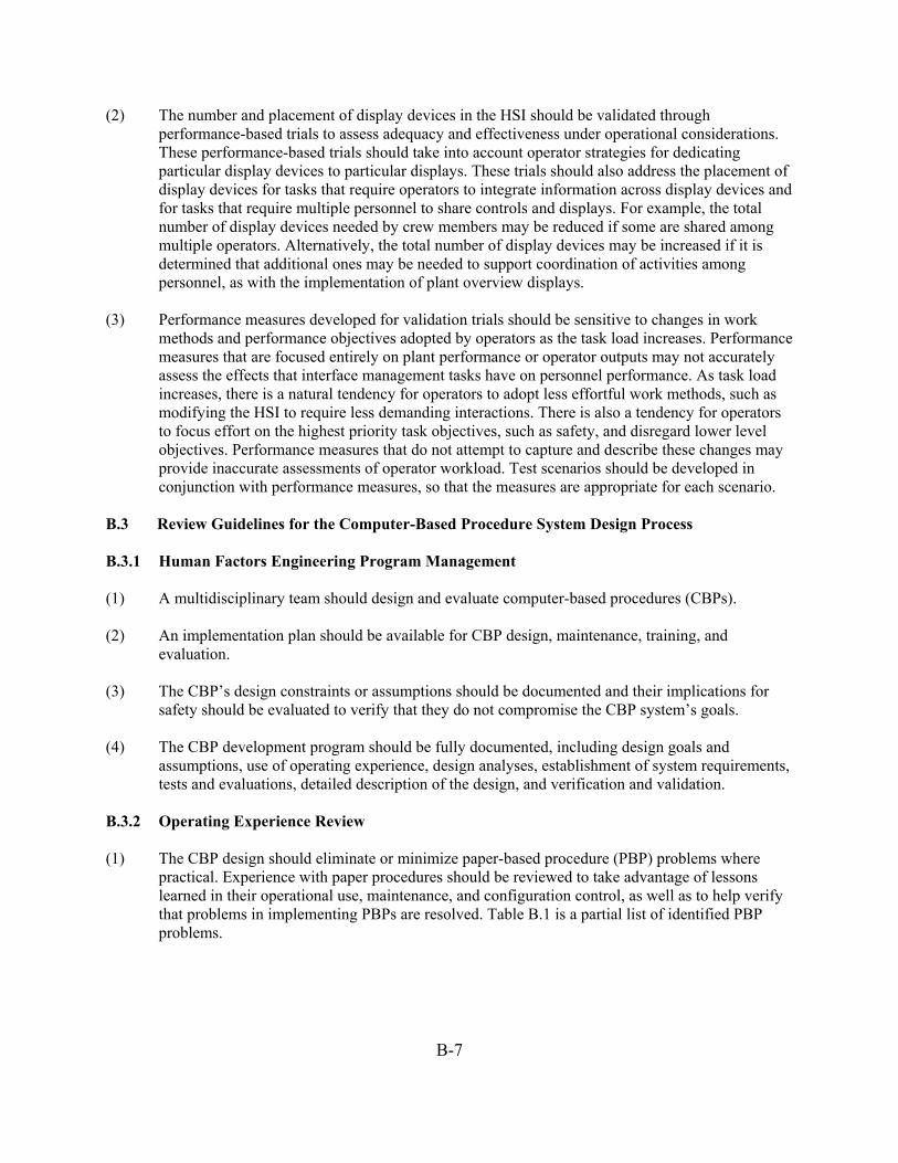
B-7
(2) The number and placement of display devices in the HSI should be validated through performance-based trials to assess adequacy and effectiveness under operational considerations. These performance-based trials should take into account operator strategies for dedicating particular display devices to particular displays. These trials should also address the placement of display devices for tasks that require operators to integrate information across display devices and for tasks that require multiple personnel to share controls and displays. For example, the total number of display devices needed by crew members may be reduced if some are shared among multiple operators. Alternatively, the total number of display devices may be increased if it is determined that additional ones may be needed to support coordination of activities among personnel, as with the implementation of plant overview displays.
(3) Performance measures developed for validation trials should be sensitive to changes in work
methods and performance objectives adopted by operators as the task load increases. Performance measures that are focused entirely on plant performance or operator outputs may not accurately assess the effects that interface management tasks have on personnel performance. As task load increases, there is a natural tendency for operators to adopt less effortful work methods, such as modifying the HSI to require less demanding interactions. There is also a tendency for operators to focus effort on the highest priority task objectives, such as safety, and disregard lower level objectives. Performance measures that do not attempt to capture and describe these changes may provide inaccurate assessments of operator workload. Test scenarios should be developed in conjunction with performance measures, so that the measures are appropriate for each scenario.
B.3 Review Guidelines for the Computer-Based Procedure System Design Process B.3.1 Human Factors Engineering Program Management (1) A multidisciplinary team should design and evaluate computer-based procedures (CBPs). (2) An implementation plan should be available for CBP design, maintenance, training, and
evaluation. (3) The CBP’s design constraints or assumptions should be documented and their implications for
safety should be evaluated to verify that they do not compromise the CBP system’s goals. (4) The CBP development program should be fully documented, including design goals and
assumptions, use of operating experience, design analyses, establishment of system requirements, tests and evaluations, detailed description of the design, and verification and validation.
B.3.2 Operating Experience Review (1) The CBP design should eliminate or minimize paper-based procedure (PBP) problems where
practical. Experience with paper procedures should be reviewed to take advantage of lessons learned in their operational use, maintenance, and configuration control, as well as to help verify that problems in implementing PBPs are resolved. Table B.1 is a partial list of identified PBP problems.

B-8
Table B.1 Examples of deficiencies in paper-based procedures
Issue Deficiency Design Process
• Inadequate participation of operations and training personnel in developing procedures
• Technically incorrect emergency operating procedures (EOPs) • Suitable under standard situations but less support in unusual situations • Incomplete procedures • Inadequate consideration of the time required to complete procedural actions • Insufficient verification and validation (V&V) of procedures
Implementation
• Nonspecific entry and exit conditions for support procedures • Fixed and inflexible procedures • Incorrect sequencing of action steps • Inadequate consistency across procedures • Inconsistencies in formatting and use of terminology • Incorrect identification of plant equipment • Inadequate provision for varying level of detail • Nonsequential presentation of information • Difficulties in navigating to related information • Inadequate management of multiple procedures • Unsatisfactory integration of procedure tasks and other tasks • Problems in labeling and headings • Notes and cautions in improper places • Lack of context-dependent highlighting and navigation • Need to use multiple procedures simultaneously and move between sections • Lack of flowcharts to guide procedure use • Inadequate support and reference material • Bulkiness • Physical handling of procedures near control panels • Separation from other information sources, such as the safety parameter
display system • Inconsistency with other HSIs in terms of references to plant equipment
Training • Operators poorly trained in using procedures Maintenance • Maintenance of technical accuracy of procedures lacking
(2) Operating experience with CBP systems should be reviewed to take advantage of lessons learned
in using the systems, as well as to verify that any problems in implementing CBPs are addressed. (3) Human performance issues, such as visual fatigue, arising from the computerization of documents
and manuals should be addressed. B.3.3 Functional Analysis (1) An overall concept should be developed of the operators’ role in managing and supervising plant
procedures.

B-9
B.3.4 Task Analysis (1) The effect of the CBP on the tasks of individual members of the crew should be analyzed,
considering any potential changes that may result from the combined use of CBPs and backup procedures, as well as the effect on communications.
(2) CBP tasks should be analyzed and used as an input to its design. B.3.5 Staffing (1) The demands of operating and maintaining the CBP should be assessed for their implications for
personnel skills and qualifications. B.3.6 Human Reliability Analysis (1) Any effects on performance caused by computerization of procedures should be analyzed for
their implications for those human actions modeled in a PRA. (2) The analysis should consider the effects on human reliability of a loss of CBPs and transfer to
backup procedures. B.3.7 Human-System Interface Design (1) The HSI design should consider methods by which procedure elements are represented in the
CBPs and the extent to which usability principles for PBPs generalize to CBP systems. (2) The procedure functions to be provided by the CBP system should be carefully analyzed to verify
that the system is consistent with the utilities’ general approach to procedure-based operations and that the operator’s inputs and judgments are included, where appropriate.
(3) The following aspects of CBP design should be carefully evaluated to verify that the use of
procedures is not jeopardized and that task requirements are adequately supported:
• number of VDUs • interface management and navigation functions • flexibility of CBP display and operations
(4) The potential interactive effects between procedure use and the hardware and software used to
implement them should be evaluated. (5) The means by which CBPs can support crew cooperation, communication, and decision making
should be evaluated. (6) Operators should be involved in developing and evaluating prototypes to verify that their final
design is usable.
B-10
B.3.8 Procedure Development B.3.8.1 Scope of Procedures (1) The purpose and scope of the CBP system should be clearly defined. B.3.8.2 Bases of Procedures Procedure bases refer to the background information used to develop the CBPs. Procedures are critical management tools because they are among the more important means of guiding human interactions with the plant systems. The procedures must not only prescribe technically correct actions but must also implement the expectations of the licensee or applicant and the NRC for the conduct of operations. Consequently, their content should be consistent with the technical, regulatory, and management bases of plant operations, no matter what medium is used to present them. (1) The technical bases for procedures should be documented. Where the documented bases for paper
procedures are unchanged by computerization, the existing document may be used. This should include the sources of technical information, as well as the process by which the information was used to define the desired operator actions and supplemental information, such as cautions and warnings, figures, and tables.
(2) The regulatory bases for procedures should be specified, and the manner in which they were
applied in developing the CBPs should be documented. (3) The management bases for procedures should be documented. (4) If the CBPs are to be implemented in an operating plant using PBPs, their impact on existing
management bases should be evaluated. (5) If the CBPs are developed for a generic plant design or for new designs, plans and methods
should be specified for incorporating the licensee- or applicant-specific management bases. Since the specific characteristics of the intended users and their work environments may not be known, the methods by which the CBPs can be tailored for them should be identified.
B.3.8.3 Technical Information (1) The selection of parameters and indicators of plant state to be monitored at each procedure step
should be reviewed. (2) The means by which the CBPs make the following types of assessments should be completely
documented and reviewed by a multidisciplinary team, including plant operators:
• conditions for entering procedures • analysis of step logic • assessment of cautions and notes • performance of calculations • assessment of exit conditions from procedures • assessment of high-level procedural goals
B-11
(3) Procedures should be specifically tailored to the intended users, their physical work environment, and the organization in which the tasks are performed.
B.3.8.4 Maintenance of Procedures (1) Methods should be specified for ensuring that procedure revisions do not introduce technical
inaccuracies or inconsistencies in how the CBPs are presented. (2) Provisions should be made for temporarily changing procedures. Administrative procedures for
introducing and handling procedure changes should identify how to properly implement the changes in the CBP system. The CBP’s interface should clearly identify these changes.
B.3.9 Training Program Development (1) The training program should address the role of the operators to ensure that they remain in control
of the CBP system and independently supervise it. (2) The designers should specify the knowledge, skills, and abilities that users will require to interact
successfully with the CBP. (3) The training requirements for using CBPs should be specified and incorporated into a training
program that should cover both initial and ongoing training. Training should consider the design features, functions, and limitations of CBPs (such as the potential for incorrect assessments).
(4) The training program should address the importance of teamwork and communication when the
CBP is being used. (5) For CBP systems used for EOPs only, the compatibility with day-to-day operations needs to be
evaluated to ensure that the system can be easily understood and used. (6) The means by which the CBP will be introduced and implemented in an operating plant should be
specified. B.3.10 Human Factors Verification and Validation (1) A V&V plan should be established. (2) V&V of procedures should verify that the CBPs are technically correct and usable. Three types of
design considerations must be addressed when evaluating their usability: (1) human factors engineering (HFE) design standards and guidelines for human-computer interaction, (2) HFE design guidelines for the format of text instructions and graphics used in presenting procedural information, and (3) the unique influence of site-specific characteristics and users. The acceptability of a CBP system cannot be determined without documentation that all three types of considerations were acceptably addressed.
(3) An independent review team should conduct V&V. (4) CBP evaluations should use several crews and scenarios. They also should use operator-in-the-
loop evaluations to verify that the system’s objectives are achieved and that any transitions between CBP and PBP are accomplished.
B-12
(5) Each CBP EOP should be evaluated in the plant’s simulator. (6) V&V should establish that crew performance is not degraded as compared with that reached
using PBPs. (7) The criteria for accepting the CBP should be specified. B.4 Review Guidelines for the Automation System Design Process B.4.1 Operating Experience Review (1) Two aspects of the operation experience review (OER) are pertinent to automation. First of all,
OER should be used to determine problem areas experienced by operators that might benefit from the application of some type of automation. Secondly, once new automation has been selected to be used in the nuclear power plant design, OER should be applied to the planned type of automation to identify potential problem areas. The design can address these potential problems to avoid negative aspects of the new automation.
B.4.2 Functional Requirements Analysis and Function Allocation (1) Alternative schemes for allocating functions should be examined in the context of the whole
system by employing high-fidelity simulations. Because there may be multiple potential schemes involved in doing so, simulating them in the context of the whole system ensures their proper evaluation. A scheme that seems to be the most appropriate for accomplishing a specific task may not be the best choice in terms of the functioning of the entire automated system.
B.4.3 Treatment of Important Human Actions (1) As part of the treatment of important human actions (HAs), applicants or licensees should specify
how the HFE program addresses important HAs to minimize the likelihood of human error and facilitate error-detection and recovery capability. Thus, each important HA should receive some consideration for the application of automation. Also, when a new application of automation is planned, any implications for and interaction with important HAs should be addressed.
B.4.4 Human-System Interface Design (1) General Principles for Human-Automation Interaction—The HSI design for human-automation
interaction should conform to the general principles described in Table B.2.

B-13
Table B.2 General principles for human-automation interaction
Principle Definition Define the purpose of automation
Automation should have a clear purpose, meet an operational need, be well integrated into overall work practices, and be sufficiently flexible to handle anticipated situational variations and adapt to changing personnel needs.
Establish locus of authority
In general, personnel should be in charge of the automation, be able to redirect it, be able to stop it, and assume control, if necessary. This does not prevent the automation from initiating actions. Some actions are allocated to automation because they cannot be reliably performed by personnel within time or performance requirements. There may be situations where automation initiates a critical action because personnel have failed to do so. Such automatically initiated actions (e.g., SCRAM), are needed to support the safety of personnel and equipment.
Optimize the performance of human-machine team
Automation should be designed so that users are involved in active monitoring and control, rather than being just passive monitors. Automation failures may be easier to detect when users are actively involved in both activities than when they are not taking part. The allocation of responsibilities between humans and machine agents should seek to optimize overall integrated team performance. This may involve defining various levels of automation, each with clear-cut, specific responsibilities for all agents and each with a clear rationale. It also may involve flexible allocations that change in response to situational demands. Personnel interactions with automation should support their development of a good understanding of the automation and the maintenance of the personal skills needed to perform tasks if automation fails. This optimization may involve exposing personnel to various levels of automation. The HSIs should support a clear understanding of the roles and responsibilities for both human and machine agents.
Understand the automation
Personnel should clearly understand the automation’s abilities, limitations, and goals, and be able to predict its actions within various contexts. Minimizing automation’s complexity will support this objective. While operators’ understanding largely will come from training and experience, the HSI should support that understanding by reinforcing the operators’ appropriate mental model through the information provided in automation displays. That is, the HSI should accurately represent how the automation functions overall and how it interacts with the plant functions, systems, and components.
Trust the automation
Personnel should have a well-calibrated trust in automation that involves knowing the situations when the automation can be relied on, those that require increased oversight by personnel, and those that are not appropriate for automation. The HSIs should support the calibration of trust, such as providing information about the automation’s reliability in its various contexts of use and specific functions.
Maintain situation awareness
The HSI with automation should provide sufficient information for personnel to monitor and maintain awareness of automation’s goals, current status, progress, processes (logic/algorithms, and reasoning bases), difficulties, and the responsibilities of all agents. Special attention should be given to changing levels of automation and for adaptive automation where the roles and responsibilities of all agents may change. HSIs should support differing levels of need for information, from determining the overall status at a glance to more detailed data in support of greater interaction with automation.
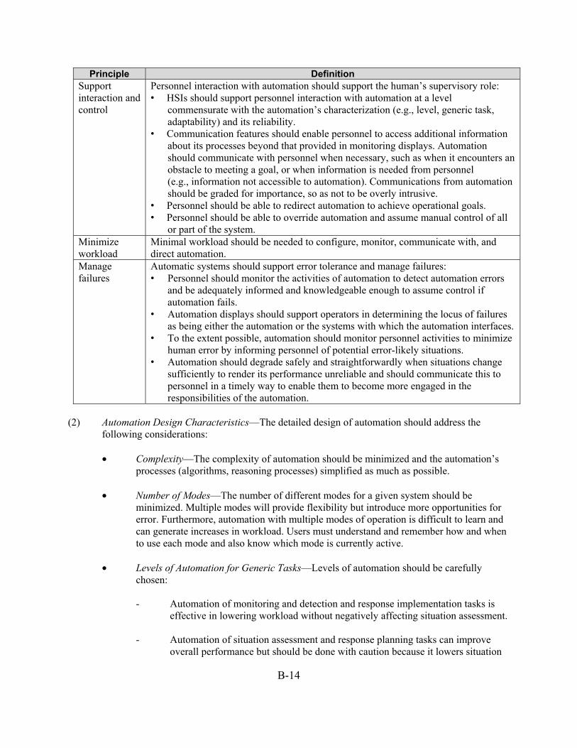
B-14
Principle Definition Support interaction and control
Personnel interaction with automation should support the human’s supervisory role: • HSIs should support personnel interaction with automation at a level
commensurate with the automation’s characterization (e.g., level, generic task, adaptability) and its reliability.
• Communication features should enable personnel to access additional information about its processes beyond that provided in monitoring displays. Automation should communicate with personnel when necessary, such as when it encounters an obstacle to meeting a goal, or when information is needed from personnel (e.g., information not accessible to automation). Communications from automation should be graded for importance, so as not to be overly intrusive.
• Personnel should be able to redirect automation to achieve operational goals. • Personnel should be able to override automation and assume manual control of all
or part of the system. Minimize workload
Minimal workload should be needed to configure, monitor, communicate with, and direct automation.
Manage failures
Automatic systems should support error tolerance and manage failures: • Personnel should monitor the activities of automation to detect automation errors
and be adequately informed and knowledgeable enough to assume control if automation fails.
• Automation displays should support operators in determining the locus of failures as being either the automation or the systems with which the automation interfaces.
• To the extent possible, automation should monitor personnel activities to minimize human error by informing personnel of potential error-likely situations.
• Automation should degrade safely and straightforwardly when situations change sufficiently to render its performance unreliable and should communicate this to personnel in a timely way to enable them to become more engaged in the responsibilities of the automation.
(2) Automation Design Characteristics—The detailed design of automation should address the
following considerations:
• Complexity—The complexity of automation should be minimized and the automation’s processes (algorithms, reasoning processes) simplified as much as possible.
• Number of Modes—The number of different modes for a given system should be
minimized. Multiple modes will provide flexibility but introduce more opportunities for error. Furthermore, automation with multiple modes of operation is difficult to learn and can generate increases in workload. Users must understand and remember how and when to use each mode and also know which mode is currently active.
• Levels of Automation for Generic Tasks—Levels of automation should be carefully
chosen:
- Automation of monitoring and detection and response implementation tasks is effective in lowering workload without negatively affecting situation assessment.
- Automation of situation assessment and response planning tasks can improve
overall performance but should be done with caution because it lowers situation

B-15
awareness and increases difficulty in recovering from automation failures. • Adaptive Automation—Adaptive automation has a positive effect on the operator’s
understanding of automation, situation awareness, and ability to recover when the automation fails. Adaptive automation is known to help support task performance and manage workload, especially for lower level cognitive functions (information acquisition and action implementation functions). The situation is more complex when it is applied to higher level cognitive functions (information analysis and decision making) and performance may be disrupted.
In adaptive automation, there can be a cognitive cost to switching between levels of automation that can disturb ongoing task performance. Thus, the design of the triggering mechanisms should be addressed carefully to minimize this issue and should be easily accomplished with the HSI.
(3) HSI Design Requirements—An HSI requirements analysis should be performed to define HSI
support for operator roles and responsibilities when interacting with automation. The design of HSIs for automation should involve an HSI requirements analysis and a detailed HSI design. The literature recommends that approaches to these two activities are work-domain analysis and ecological interface design. Both generally are consistent with the NRC staff’s guidance for reviewing the design process (NUREG-0711), and HSI design implementation (NUREG-0700).
(4) Determine the Impact of Automation on Team Performance—When introducing new automation,
designers should consider the possibility of negative effects on team coordination. Automation may lower team interaction and cooperation unless all parties are given information that allows them to be actively involved in the task. Automation can cause physical difficulty in seeing what other team members are doing, reduce the ability to cross-monitor actions, change traditional roles and responsibilities, and change the manner in which team members attempt to help each other.
(5) Evaluate Interactions with Other Functions—Possible interactions with other tools, system
functions, and user tasks should be assessed when new automation is designed. (6) Test Normal and Failure Modes—Automated systems should be tested under normal operations
and under their failure modes and degraded conditions. B.4.5 Procedure Development (1) The implementation of automation should be fully addressed by appropriate procedural coverage.
This should include procedures for the following:
• operation of the automation system • operation of affected systems and components • degradation and failure of the automation system • initial and surveillance testing of the automation • maintenance of the automation system
B-16
B.4.6 Training Program Development (1) Training should be directed to establishing a clear understanding for operators of automation’s
capabilities and limitations. They should understand the following:
• the purpose of automation, design bases, and range of applications in a way that relates to the user’s goals
• automation’s operational goals
• how automation works
• how it interacts with the plant functions, systems, and components
• automation’s expected reliability, the mechanisms governing its behavior, and its intended use
• how to predict its actions within its various contexts of use (2) Training should result in an accurate understanding of the automation. (3) Training should clearly identify the role of personnel in supervising and interacting with all levels
of automation. (4) Training should address the limits of automation. That information will help operators to establish
and maintain a proper level of trust in the automation and avoid problems associated with overreliance (using automation when it should not be used) and not using (or ignoring) automation when it should be used. The operator’s trust in automation should be tested and measured to ensure it is appropriate for each context in which automation is used.
(5) Training should address automation monitoring strategies. Personnel should monitor the activities
of automation to detect its errors and to be in an informed and knowledgeable position to assume control if it fails.
(6) Training should specifically address available modes, how to track them, the impact of the mode
differences on automation’s behavior, and the consequences of mode-related errors. (7) Training should specifically address failure-recovery transitions. Users should be trained on
transitioning from automated to conventional systems. If automation fails, users need to be skilled at recognizing the failure and taking manual control. Simulator training specifically should offer experience with automation reliability and failures. Exposure to failures helps operators to develop well-calibrated trust and failure-recovery skills.
(8) Training should specifically include backing-up automation. Users should have training in
undertaking any manual tasks replaced by automation, or in operating any backup systems controlled by automation. Training should ensure that manual skills are not degraded so that personnel can effectively assume control when needed.
B-17
(9) Training should specifically cover the impacts of automation on team performance. While automating lower-level cognitive functions, such as monitoring, data gathering, and response execution were beneficial to teamwork, automating higher-level cognitive functions such as decision making is sometimes detrimental.
(10) Training and operational practices should address providing intermittent manual control to
improve the operator’s monitoring and manual-recovery behaviors. This reinforcement should help minimize complacency and maintain skills.
(11) Where available, training and operational practices should address using adaptive automation to
mitigate the loss of skills. B.4.7 Human Factors Verification and Validation (1) Automated systems should be tested in a realistic operational environment with representative
users before implementing them to ensure that the operator’s performance is not compromised and workload is not increased. Contextually valid human-in-the-loop experiments and simulations should be conducted to validate the design of the automated system.
(2) The overall impact of automation should be thoroughly examined before its implementation to
ensure that changes do not cause additional complexities, loss of situational awareness, or possible errors. Automating some user tasks may result in the user processing less information or processing information at less depth. A diminished understanding and appreciation for the overall situation may result.
B.5 Review Guidance for Degraded HSI and I&C Conditions Design Process B.5.1 Operating Experience Review (1) Applicants should review operating experience to identify the effects of failure modes and
degraded conditions of the HSI and I&C subsystem on personnel performance.
Additional Information: Review Criterion 4 in NUREG-0711, Section 3, “Operating Experience Review,” identifies topics to be included in the review and in interviews with plant personnel. They include instrument failures, including system logic and control units; HSI equipment and processing failures (e.g., loss of VDUs or of data processing); and transients, such as a loss of power to selected buses or the control room’s power supplies. This guideline generalizes the NUREG-0711 criterion to the entire I&C system. There is limited general knowledge from operating experience with digital I&C systems that relates to HSIs and personnel performance. Thus, applicants should proactively seek this information for I&C designs that are similar to their own and use it as input to their HFE program.
B.5.2 Task Analysis (1) The applicant’s task analysis should identify the task requirements for managing HFE-significant
HSI and I&C degradations so that risk-important tasks can be performed.
Additional Information: Task analysis is the means by which the task requirements for managing I&C degradations are identified. Those requirements are needed to define the features of the HSI design needed to support operators in monitoring and responding to such degradations. The analysis should also include

B-18
tasks associated with failure and transition to backup systems; for example, transitioning to paper procedures upon failure of a CBP system.
(2) Applicants should determine the necessary compensatory actions and supporting procedures
required to ensure that personnel can effectively manage the HFE-significant I&C degradation and the transition to backup systems.
Additional Information: Managing I&C degradations requires more than good HSIs. The actions to be taken should be analyzed and the need for procedural support also determined to help operators manage the condition.
B.5.3 Treatment of Important Human Actions (1) The applicant’s PRAs and HRA activities should provide input to determining the impact of
HFE-significant I&C degradations on human error and plant risk.
Additional Information: Recent approaches to HRA recognize the importance of the potential impact of sensor failure on the operator’s situation assessment, and, in turn, the effect of incorrect ones on errors of commission (e.g., Kim, Jung, and Park, 2005; Kim, Jung, and Son, 2008; and NUREG–1624, “Technical Basis and Implementation Guidelines for A Technique for Human Event Analysis (ATHEANA),” Revision 1) (NRC, 2000). For example, ATHEANA recognizes the importance of situation assessment on human action and error (NRC, 2000). Factors leading to faulty assessments are identified as part of the analysis, including sensor failures. This leads to efforts to predict errors of commission resulting from poor situational assessment. ATHEANA’s HRA methods are useful in the current context, in that they afford possible approaches to analyzing sensor degradations to identify those that might lead to incorrect situation assessments.
The analyses will support the applicant’s efforts to address the staff’s interim staff guidance (DI&C-ISG-03), “Review of New Reactor Digital Instrumentation and Control Probabilistic Risk Assessments” (NRC, 2008). The guidance notes that human errors associated with digital I&C system failures have become more important contributors to core damage frequency and highlights the following considerations that applicants should address in their PRAs:
• Evaluate the acceptability of how the failure of control room indication is modeled.
• Assess the acceptability of the recovery actions taken for a loss of digital I&C functions, referring
to Regulatory Guide 1.200, “An Approach for Determining the Technical Adequacy of Probabilistic Risk Assessment Results for Risk-Informed Activities” (NRC, 2009a) and HRA good practices in NUREG-1792, “Good Practices for Implementing Human Reliability Analysis” (NRC, 2005) for guidance. If recovery actions are modeled, they should consider loss of instrumentation and the time available to complete such action.
• Ensure that, for self-testing and diagnostic features, the PRA accounts for the possibility that the system does not reconfigure itself after detecting a failure. Also, a diagnostic feature may not detect all of the failure modes, only those it was designed to discover.
• If a communication network is shared, the effects on all systems because of failures of the network should be modeled jointly. “The impact of communication faults on the related components or systems should be evaluated.”
• Interactions within a digital I&C system should be considered (multitasking, multiplexing).

B-19
B.5.4 Human-System Interface Design (1) Applicants should conduct analyses to identify HFE-significant I&C degradations (i.e., the failure
modes and degraded conditions of the I&C system) that could potentially affect the HSIs used by personnel in carrying out important human actions.
Additional Information: There are three key points about this review guideline: (1) Analysis of the effects of I&C degradations on HSIs and personnel performance, (2) evaluation of degraded conditions in addition to complete failure, and (3) focusing the analysis on the impacts on operations. Each is discussed below.
While applicants typically analyze the effect of I&C failure modes and degradations on key plant systems, they do not expand it routinely to HSIs and personnel performance. For example, one study found that extending a designer’s failure modes and effects analysis to include how the failures affect the HSIs can identify potential human performance impacts that can be addressed in system design (O’Hara, Gunther, and Martinez-Guridi, 2010). The ways in which resources, such as computer-based procedures and other HSIs can degrade should be analyzed and understood fully so they can be dealt with in the HFE program to ensure personnel perform risk-important tasks correctly.
Attention should be paid to degradations, not just complete failure. Complete failure, such as that of a computer-based procedures system, is easily recognized, and existing guidance already specifies the need for a backup system. More subtle degradations may be troublesome to discern yet may affect the information provided by HSIs, and thus, personnel performance.
There are very many HSIs in modern nuclear power plants, so analyzing all of them may be impractical. Thus, evaluations may be applied in a graded fashion, by identifying the more important human actions and the HSIs most closely related to plant safety. Many lower level digital I&C failures that occur do not affect I&C system functionality from an operations perspective; maintenance personnel resolve them as part of their normal activities. The key in this guideline is identifying those degradations that lower the ability of personnel to monitor, detect, and assess situations, plan responses, and implement responses associated with important tasks. A degraded digital I&C system power supply is an example of an analysis that should be conducted because of the likelihood of affecting the HSI.
The effects of instrumentation failures on graphic displays should be carefully analyzed. Potential failure problems should be evaluated in the context of the following questions: • Can operators detect a failure of instrumentation? • Can instrument failures result in representations that operators interpret as real process failures;
perhaps more importantly, can such process failures be misinterpreted as instrument failures? • If operators detect a failure, should use of the display be suspended? • Since the display may integrate many parameters into a single visualization, what effect does its
loss have on operations and how effectively can operators transition to backup displays? This guidance is consistent with that in Institute of Electrical and Electronics Engineers (IEEE) Standard (Std.) 7-4.3.2-2003 (IEEE, 2003), specifying that a hazard analysis be undertaken to identify conditions that are not identified by the normal design review and testing process. “The hazard analysis extends beyond plant design basis events by including abnormal events and plant operations with degraded equipment and plant systems.” Section D.4.2.3.2 states that techniques, such as fault tree analysis and failure modes and effects analysis, can be used to determine hazards. Section D.4.2.4.4 of this standard acknowledges that “the system-level impact of a hazard may be subtle, such as the display of an erroneous value that subsequently causes an operator to take an inappropriate action.”

B-20
(2) Applicants should analyze the impacts of HSI and I&C degradations to ensure that they are not displayed in HSIs in ways that personnel will confuse with other process disturbances.
Additional Information: One concern about HSI and I&C degradations, particularly of the sensor and monitoring subsystem, is that they can (1) render displays difficult to interpret, and (2) perhaps worse, can make displays look as though a process disturbance has occurred. Analyses during the design process will help ensure that their effects are understood and the opportunity for misleading operators is minimized. The literature includes a variety of approaches to resolving this concern, including human reliability analysis (NRC, 2000), confusion matrices (Kim and Seong, 2008), and misdiagnosis tree analysis (Kim, Jung, and Park, 2005; Kim, Jung, and Son, 2008).
The analyses conducted for this guideline will support the applicant’s ability to address the issues in DI&C-ISG-03, “Digital I&C; Highly-Integrated Control Rooms-Communications Issues” (NRC, 2009b). Section 3.2, “Human Factors Considerations,” cites the potential for providing operators with obsolete or erroneous information without advising them of potential inaccuracies. It states that applicants should demonstrate that they have considered these kinds of issues. The guidance is also consistent with IEEE Std. 603-1998 (IEEE, 1998) and IEEE Std. 497-2002 (IEEE, 2002). IEEE Std. 603-1998 states, “The design of the information display system shall minimize the possibility of ambiguous indications that could be confusing to the operator” and IEEE Std. 497-2002, Section 6.5, “Information Ambiguity,” states “… the failure of an accident monitoring instrument channel shall not result in information ambiguity that could lead the operator to defeat or fail to accomplish a required safety-related function.” “If analysis shows that credible failures can result in information ambiguity, a signal validation technique should be employed. If the signal validation process cannot be automatically accomplished, additional information shall be provided to allow the operators to deduce the actual conditions so that they may properly perform their role.”
(3) Applicants should determine the alarms and the information personnel need to detect
HFE-significant I&C degradations in a timely manner and to identify the extent and significance of the condition.
Additional Information: This information is an essential input to designing HSIs that will be effective in supporting operators to detect and manage degraded conditions.
(4) Applicants should determine the necessary backup systems, if any, needed to ensure that
risk-important tasks can be performed.
Additional Information: Depending on the extent of redundancy and diversity in the I&C systems involved and the type of support given to operators, backup systems may be necessary. For example, if there is a major loss of digital I&C, a backup may be needed to manage safety functions.
B.5.5 Training Program Development (1) Operator training programs should support personnel in the following ways:
• understanding how and why the HSIs and I&C subsystems might degrade or fail
• knowing the implications of such degradations for HSI and their own task performance
• monitoring the I&C system’s performance, so degradations and failures are detected and recognized through the control room HSIs (e.g., recognizing display format failure modes and effects on the graphical presentation)

B-21
• performing recovery actions and compensatory actions in the event of degraded
conditions
• determining when to override degraded systems
• smoothly transitioning to backup systems when needed and returning when system functions are restored
• comprehending how the roles and responsibilities of crew members and the concept of operations will be affected by degraded HSI and I&C conditions
Additional Information: Operator training plays an important role in supporting operators who detect degradations and in understanding the types of degraded conditions that can occur. For example, for failures of automatic systems, classroom learning, and on-the-job training are enhanced by simulator training that specifically provides operators with experience of different failures (O’Hara and Higgins, 2010).
B.5.6 Human Factors Verification and Validation (1) HFE-significant I&C degradations should be addressed by integrated system validation to ensure
that measures taken in designing HSIs, developing procedures, and training operators will successfully mitigate the potential effects of these conditions on personnel performance of risk-important tasks.
Additional Information: This guidance is a more complete treatment of HSI and I&C degradations than exists in the current guidance. As part of the sampling of operational conditions, NUREG-0711, Section 11.4.1.2, “Review Criterion 1” identifies “I&C and HSI failures and degraded conditions” as a sampling dimension. This guideline provides more information about the aspects of these conditions that should be considered in validation.
References Institute of Electrical and Electronics Engineers (2003). IEEE Standard Criteria for Digital Computers in Safety Systems in Nuclear Power Generating Stations (IEEE Std. 7-4.3.2-2003). New York, NY: Institute of Electrical and Electronics Engineers. Institute of Electrical and Electronics Engineers (2002). IEEE Standard Criteria for Accident Monitoring Instrumentation for Nuclear Power Generating Stations (IEEE Std. 497-2002). New York, NY: Institute of Electrical and Electronics Engineers. New York, NY: Institute of Electrical and Electronics Engineers. Institute of Electrical and Electronics Engineers (1998). IEEE Standard Criteria for Safety Systems for Nuclear Power Generating Stations (IEEE Std. 603-1998). New York, NY: Institute of Electrical and Electronics Engineers. Kim, J, Jung, W. and Park, J. (2005). “A systematic approach to analyzing errors of commission from diagnosis failure in accident progression.” Reliability Engineering and System Safety, 89, 137–50. Kim, J, Jung, W. and Son, Y. (2008). “The MDTA-based method for assessing diagnosis failures and their impacts in nuclear power plants.” Reliability Engineering and System Safety, 93, 337–349.

B-22
Kim, M. and Seong, P. (2008). “A method for identifying instrument faults in nuclear power plants possibly leading to wrong situation assessment.” Reliability Engineering and System, 93, 316-324. O’Hara J., Gunther, W., and Martinez-Guridi, G. (2010). The Effects of Degraded Digital Instrumentation and Control Systems on Human-System Interfaces and Operator Performance (BNL Technical Report No. 91047-2010). Upton, NY: Brookhaven National Laboratory. O’Hara J. and Higgins, J. (2010). Human-System Interfaces to Automatic Systems: Review Guidance and Technical Basis (BNL Technical Report 91017-2010). Upton, NY: Brookhaven National Laboratory. U.S. Nuclear Regulatory Commission (2000). Technical Basis and Implementation Guidelines for a Technique for Human Event Analysis (ATHEANA). NUREG-1624, Rev. 1. Washington, DC: U.S. Nuclear Regulatory Commission. U.S. Nuclear Regulatory Commission (2005). Good Practices for Implementing Human Reliability Analysis (HRA). NUREG-1792. Washington, DC: U.S. Nuclear Regulatory Commission. U.S. Nuclear Regulatory Commission (2008). Review of New Reactor Digital Instrumentation and Control Probabilistic Risk Assessments: Interim Staff Guidance. DI&C-ISG-03.) Revision 0, August 11, 2008. Washington, DC: U.S. Nuclear Regulatory Commission. Agencywide Documents Access and Management System ADAMS Accession No. ML080570048. U.S. Nuclear Regulatory Commission (2009a). An Approach for Determining the Technical Adequacy of Probabilistic Risk Assessment Results for Risk-Informed Activities. Regulatory Guide 1.200. Washington, DC: U.S. Nuclear Regulatory Commission. U.S. Nuclear Regulatory Commission (2009b). Digital I&C; Highly-Integrated Control Rooms-Communications Issues (DI&C-ISG-04, Rev. 1). Washington, DC: U.S. Nuclear Regulatory Commission. ADAMS Accession No. ML083310185.

C-1
APPENDIX C: CHANGES MADE TO NUREG-0700, REV. 2, TO DEVELOP REV. 3 The U.S. Nuclear Regulatory Commission (NRC) has not updated NUREG-0700 since 2002, so most of its sections are being revised. The update is being conducted using a phased approach. Revision 3 is the result of the first phase of the update, which addressed the following sections: • Section 3—Controls • Section 4—Alarm System • Section 5—Safety Function and Parameter Monitoring System • Section 9—Computerized Operator Support System (COSS) • Section 11—Workstation Design • Section 12—Workplace Design • New Section 14—Degraded Human-System Interface (HSI) and Instrumentation and Control
(I&C) Conditions In addition to these major section updates, we made other general changes, as well. In this appendix, we summarize these changes. The other sections of NUREG-0700 will be updated in a future revision. Section 1—Information Display We deleted the characterization description and the review guidance for display devices. These were updated and moved to Section 11, “Workstation Design.” Guidelines 1.1-21 through 1.1-23 and 1.4-9 through 1.4-11 were deleted or combined with the new guidance on degraded HSI and I&C conditions in Section 13. Section 2—User Interface Interaction and Management Guidelines 12.1.1.11-1 and 12.1.1.11-5 were moved from Section 12 to Section 2 as Guidelines 2.8-4 and 2.8-5. This is a more appropriate location, based on their content. Guideline 2.5.1.1-9 was deleted because of its general content. Section 3—Controls
This section does not contain new guidance. It contains an integration of the review guidance for analog HSIs into this section (Section 3). We made the following modifications: (1) We changed the name of the section to “Analog Control and Display Devices.” (2) We moved all the review guidance for analog control and display devices to Section 3. Table C.1
shows the origin of the NUREG-0700, Rev. 2, guidelines that are not in this Rev. 3 section. We also did some minor editing, added metric values, and fixed several figures.

C-2
Table C.1 Source of NUREG-0700, Rev. 3, Section 3, review guidelines
Rev. 3 Section Imported from Rev. 2 Section 3.1 Analog Controls 3.1.1 General Control Guidelines Section 3.1 3.1.2 Pushbuttons Section 3.3.1 3.1.3 Slide Switches Section 3.3.3.2 3.1.4 Toggle Switches Section 3.3.3.3 3.1.5 Rocker Switches Section 3.3.3.4 3.1.6 Rotary Controls Section 3.3.2 3.1.7 Manual Valves Section 12.2.3.2 3.2 Analog Display Devices 3.2.1 Meters Section 1.6.4 3.2.2 Light Indicators Section 1.6.5 3.2.3 Numeric Readouts Section 1.6.6 3.2.4 Valve Position Indication Section 12.2.2.3
(3) We moved the review guidance for computer-based devices to other sections. Specifically,
Rev. 2, Section 3.2, “Input Devices (Computer),” was moved to Rev. 3, Section 11.3.2, “Computer Input Devices,” in the Workstation Design section.
Section 4—Alarm System This section was updated to reflect new principles for the design of alarm systems. The following specific changes were made to the section. Alarms Integrated into Other Displays We developed a new Section 4.2.9 to provide review criteria for alarms integrated into other displays, such as mimic diagrams, computer-based procedures, and soft control displays. NUREG-0700, Rev. 2, identified three basic types of alarm displays: • spatially dedicated, continuously visible alarm displays (e.g., tiles) • alarm message lists (e.g., temporary alarm displays) • alarms integrated into process displays While review guidance was presented for the first two, guidance was not available for the latter type. Based on recent research and publications, we developed review guidance for these alarms. The resulting review guidance is included in NUREG-0700 as new Section 4.2.9, “Alarms Integrated into Other Displays.” Related to this new section, we eliminated the heading 4.2.7, “Organization of Alarms.” This section contained two subsections, 4.2.7.1, “Spatially Dedicated, Continuously Visible Alarm Displays,” and 4.2.7.2, “Alarm Message” lists. These two subsections were renumbered 4.2.7 and 4.2.8, respectively. The new section on integrated alarms follows as Section 4.2.9. We did not think the term “organization of alarms” was an accurate reflection of the guidance contained within.

C-3
Routing of Alarms Digital I&C systems can significantly increase the number of available alarms in a plant. However, not all of these alarms should be sent to control room operators. An example is I&C diagnostic alarms. These are alarms used by maintenance personnel; thus, they are not necessarily important to operators. Routing alarms to the appropriate personnel can help reduce the number of alarms that operators must address. Thus, we developed a new Section 4.1.4 to provide review criteria for alarm routing. For some of the alarms routed to maintenance personnel, operators may still need to be notified of their operational significance if it affects their responses, such as increasing monitoring of the system, preparing to bring standby equipment into operation as a contingency, or simply being aware that maintenance actions will be required in a particular location. Alarm Recording We developed new guidance on alarm recording, which is now included in new Section 4.1.5. Time Stamping of Alarms Alarm time and the chronological sequence of alarms, events, and process data are critical to the ability of operators and engineers to diagnose plant upsets and perform postevent analyses. This is also important for correct implementation of “first out” capability. While identifying the time at which alarms occur and clear was implied in NUREG-0700’s review guidance, it was not explicitly stated, as were other detailed contents of alarm messages, such as an alarm’s priority. Thus, new Guideline 4.2.5-5, “Alarm Time,” was added to Section 4.2.5, “Alarm Contents.” Multiunit Alarms We added information to 4.2.1-6, “Additional Information,” that the alarm display layout for a multiunit control room could duplicate an alarm for a shared system. Section 5—Safety Function and Parameter Monitoring System The main focus of the update to this section was (1) to integrate all available human factors engineering (HFE) review information on safety function monitoring contained in various NRC documents to ensure consistency, and (2) to accommodate nonlight-water reactor plant designs. (1) We changed the Section title from “Safety Function and Parameter Monitoring System” to
“Safety Parameter Display System” (SPDS) for the following reasons.
• SPDS is the name used in the regulations, thus applicants still use this term.
• NRC safety evaluation reports use the term SPDS.
• Comments from outside users of NUREG-0700 stated that there is no system in nuclear power plant control rooms called “Safety Function and Parameter Monitoring System.”
(2) The SPDS characterization was revised to provide a description of the background to SPDS
reviews, to identify supporting documents, and to clarify the relationship of NUREG-0711, “Human Factors Engineering Program Review Model,” issued November 2012, and
C-4
NUREG-0700 in the staff’s review of an applicant’s SPDS. (3) For guidelines that address specific requirements in Title 10 of the Code of Federal Regulations
(10 CFR), we included the 10 CFR wording in the additional information. (4) We added references to “safety functions” to several guidelines and included a discussion
referencing NUREG-0711 guidance about defining the safety functions in the introduction to Section 5 and in the additional information of the first review guideline. We also added a reference to the NUREG-0711 definition of “safety functions.” This definition encompasses both accident and severe accident conditions (per NUREG-0737, “Clarification of TMI Action Plan Requirements,” issued January 1983, Supplement 1, p. 8).
(5) The term “critical” was deleted when referencing safety functions. This term is not used in the
regulations or in the main guidance upon which SPDS review criteria are based: NUREG-0696, “Functional Criteria for Emergency Response Facilities,” issued February 1981; NUREG-0835, “Human Factors Acceptance Criteria for the Safety Parameter Display System,” issued 1981; and NUREG-0737, Supplement 1. We indicated, in the definition of safety functions, that the term “critical safety functions” is sometimes used.
(6) The guidelines were reorganized to provide for a more logical flow. Many guidelines were
renamed and reworded for clarity and consistency across guidelines. In addition, several guidelines were eliminated and others were combined because of similar content.
(7) References used in NUREG-0800, “Standard Review Plan for the Review of Safety Analysis
Reports for Nuclear Power Plants, LWR Edition,” Revision 2, issued June 1987, were removed because (1) the guidance is from an old version of NUREG-0800 that is not readily available, and (2) the guidance in the old version of NUREG-0800 comes from NUREG-0835. Thus, we added the references to the source fields of the guidelines.
(8) Modifications were made to ensure that all the guidance is technology neutral. Light-water
reactor (LWR)-specific information is only used as examples. (9) We also added Table 5.1 that provides examples of safety functions and associated parameters for
pressurized-water reactors (PWRs), boiling-water reactors (BWRs), high-temperature, gas-cooled reactors (HTGRs), and liquid metal reactors (LMRs). The table is intended to provide examples that illustrate the safety functions and parameters for the designs identified. It is not meant to be complete or be used to assess any one design. The example functions and parameters are based on the following: The PWR and BWR typical safety functions and parameters are from Lapinsky et al. (1989). The PWR and BWR safety function, “Containment Basemat/Core Catcher Cooling,” illustrates a post core melt (severe accident) function. The PWR example is based on the U.S. EPR (AREVA, 2011), and the BWR example is based on the ESBWR (NRC, 2011). The HTGR example is from Idaho National Laboratory (INL) (2011). The LMR example is based on a sodium-cooled design (ANL, 2005). The table was initially compiled by the project staff. Then two Brookhaven National Laboratory (BNL) scientists who are experts in these designs reviewed the table entries for the HTGR and LMR designs, and revisions were made accordingly.
(10) The terms “parameters” and “variables” were used interchangeably in NUREG-0700, Revision 2.
We revised all the guidance to refer to “parameters,” rather than variables, for consistency and to avoid potential confusion in the use of two different terms. Parameter is also a more accurate term for this application, as used in 10 CFR 50.34(f)(2)(iv).

C-5
(11) We added references to other related guidelines in NUREG-0700. These often provide additional
information that can support a reviewer’s interpretation of the SPDS information. References AREVA (2011). U.S. EPR Final Safety Analysis Report, Chapter 6, Engineered Safety Features, and Chapter 19, PRA and Severe Accident Evaluation. Washington, DC: U.S. Nuclear Regulatory Commission. Argonne National Laboratory (2005). Small Modular Fast Reactor Design Description (Report ANL-SMFR-1). Argonne, IL: Argonne National Laboratory. Idaho National Laboratory (2011). Modular HTGR Safety Basis and Approach (Report INL/EXT-1 1-22708). Idaho Falls, ID: Idaho National Laboratory. Lapinsky, G., Eckenrode, R., Goodman, P., and Correia, R. (1989). A Status Report Regarding Industry Implementation of Safety Parameter Display System (NUREG-1342). Washington, DC: U.S. Nuclear Regulatory Commission. Section 6—Group-View Display System We deleted the characterization description and the review guidance for group-view display devices. These were updated and moved to Section 12, “Workplace Design.” Section 7—Soft Control System We moved the following three guidelines from Section 12 to Section 7: • 12.1.1.11-2 to 7.1-2 • 12.1.1.11-3 to 7.1-3 • 12.1.1.11-6 to 7.1-4 Section 8—Computer-Based Procedure System We modified the review guidance in Section 8.5 on computer-based procedure (CBP) backup to remove references to paper procedures and, instead, made no assumption about backup technology. Section 9—Computerized Operator Support Systems Computerized operator support systems (COSSs) are operator aids that support situation analysis and decision making. COSSs are “knowledge-based” aids that provide assessments of plant conditions and typically do not involve controls. An example of a COSS is a decision aid for nuclear power plant operators that identifies severe accidents and makes mitigation response recommendations. COSSs are systems that support operators by automating parts of the situation assessment and decision making processes. This section has undergone a major update to extend its application beyond COSSs to human-automation interaction, in general. The new section includes COSSs but also provides review guidance for other aspects of human-automation interaction, such as monitoring displays, automation modes, levels of

C-6
automation, adaptive automation, and interaction with automation. The guidance included in this section is the result of an NRC research project described in Human-System Interfaces to Automatic Systems: Review Guidance and Technical Basis (O’Hara and Higgins, 2010). The guidance in this technical report was later updated in a report entitled Development of NUREG-0700 Review Guidance for Automation Systems (O’Hara, 2015). The expansion of this section from COSSs to automation systems in general led to a change in the section title to “Automation Systems.” In addition to design review guidance, the research identified a number of design process implications. These are included in NUREG-0700, Appendix B, “Design Process Guidelines” (see the description below). References O’Hara, J. (2015). Development of NUREG-0700 Review Guidance for Automation Systems (BNL Technical Report No. 67653). Upton, NY: Brookhaven National Laboratory. O’Hara, J., and Higgins, J. (2010). Human-System Interfaces to Automatic Systems: Review Guidance and Technical Basis (BNL Technical Report No. 91017-2010). Upton, NY: Brookhaven National Laboratory. Section 11—Workstation Design The review guidance needed for Workstation Design mainly centered on the fact that the current guidance is mostly intended for analog workstations, and significant updating was needed to address computer-based workstations. New nuclear power plant control rooms have primarily computer-based workstations where operators sit to perform their tasks. The workstations often contain selected analog HSIs for controlling emergency safety functions and to back up other key functions. NUREG-0700 was updated to provide guidance for these types of workstations. This resulted in an extensive revision and reorganization of Section 11. Key documents used to support the update included: • ANSI/HFES (2007). Human Factors Engineering of Computer Workstations (American National
Standards Institute (ANSI)/HFES 100-2007)
• DoD (2012). Department of Defense Design Criteria Standard: Human Engineering, U.S. Department of Defense (MIL-STD-1472G)
• NASA (2011). NASA Space Flight Human-System Standard Volume 2: Human Factors,
Habitability, and Environmental Health (National Aeronautics and Space Administration 3001, Vol. 2)
• ISO (2011). Ergonomics of Human-System Interaction - Part 303: Requirements for Electronic
Visual Displays (International Organization for Standardization (ISO) 9241-303:2011)
• ISO (2004). Ergonomic Design of Control Centers, Part 4: Layout and Dimensions of Workstations (ISO 11064-4:2004)

C-7
This revision incorporates some material from other sections of NUREG-0700 into this workstation section (e.g., guidance on video monitors (previously in Section 1) and computer-input devices (previously in Section 2)). This section contains a lot of updated measurements that reflect, in part, changes in population anthropometrics. Many standards use the metric system. We did conversions to the English system. When this is done, the English numbers can appear overly precise. For example, if the standard says 10 cm, we convert it to 25.4 in. This is an artifact of the conversion process. The discussion below is a summary of the key changes to the workstation design review guidance. Section Changes Section 11.1, General Workstation Guidelines—This is a new section addressing configuration, posture support, and user safety. It was developed from the new source documents. Section 11.2, Workstations Containing Primarily Analog HSIs—This section is a significantly updated and reorganized version of the following subsections of Rev. 2: • Section 11.1, “Workstation Configuration”—excluding Section 11.1.5, “Desk Dimensions,”
which is now in Section 11.3.4, and Section 11.1.6, “Chairs,” which is now in Section 11.5.
• Section 11.2, “Control and Display Device Layout” • Section 11.4, “Panel Layout” In addition to some subsections, some individual guidelines have been relocated, as well. The reasons are indicated in the comments for those individual guidelines. Section 11.3, Workstations Containing Primarily Computer-Based HSIs—This section is new. Section 11.3.1, Visual Display Devices—This new section replaces Section 1.6.1, “Video Display Units,” from Rev. 2. Section 11.3.2, Computer Input Devices—This section replaces Section 3.2, “Input Devices” (“Computer Input Devices”), from Rev. 2. Some of the guidance from that Rev. 2 section has been integrated into this section. Section 11.3.3, Hand-Held Devices—This section is new. Section 11.3.4, Desktops and Work Surfaces—This section is an update of Rev. 2, Section 11.1.5, “Desk Dimensions.” Many of the guidelines have been updated and new guidance added. Section 11.3.5, Workstation Support Devices—This section is new. Section 11.5, Chairs and Footrests—All guidelines in Rev. 2, Section 11.1.6, “Chairs,” were deleted and replaced with the new guidelines in this Section 11.5.

C-8
References American National Standards Institute /Human Factors and Ergonomic Society (2007). Human Factors Engineering of Computer Workstations (ANSI/HFES 100-2007). New York, NY: American National Standards Institute. International Organization for Standardization (2011). Ergonomics of Human-System Interaction—Part 303: Requirements for Electronic Visual Displays (ISO 9241-303:2011). Geneva, Switzerland: International Organization for Standardization (ISO). International Organization for Standardization (2004). Ergonomic Design of Control Centers, Part 4: Layout and Dimensions of Workstations (ISO 11064-4:2004). Geneva, Switzerland: International Organization for Standardization (ISO). National Aeronautics and Space Administration (2011). NASA Space Flight Human-System Standard Volume 2: Human Factors, Habitability, and Environmental Health (NASA 3001, Vol. 2). Washington, DC: National Aeronautics and Space Administration. U.S. Department of Defense (2012). Department of Defense Design Criteria Standard: Human Engineering (MIL-STD-1472G). Washington, DC: U.S. Department of Defense. Section 12—Workplace Design The workplace guidance in NUREG-0700, Rev. 2, was mainly focused on analog control rooms and significant updating was needed to address computer-based control rooms. Modern control rooms consist of one or more computer-based workstations and large group-view displays that can be seen by the entire crew. We updated the review guidance to address the design and layout of this type of control room. In addition, we updated the guidance on lighting and environmental factors. Key documents used to support the update included the following: • DoD (2012). Department of Defense Design Criteria Standard: Human Engineering
(MIL-STD-1472G)
• FAA (2003). Human Factors Design Standard, Federal Aviation Administration (HF-STD-001)
• ISO (2005). Ergonomic Design of Control Centers, Part 6: Environmental Requirements for Control Centres (ISO 11064-6:2005)
• NASA (2011). NASA Space Flight Human-System Standard Volume 2: Human Factors,
Habitability, and Environmental Health (NASA 3001, Vol. 2) The discussion below contains a summary of the key changes to the workplace design review guidance. Section Changes In Section 12.1, Control Rooms
12.1.1.1, Architectural Features—This is a new section.

C-9
12.1.1.3, Group-View Display Devices—This section is made up of guidelines from Section 6.3, “Group-View Display Devices,” and Section 1.6.2, “Projectors,” modified as shown. Some new guidelines have been added. What remains in Section 6 is guidance for the review of group-view display functionality. 12.1.1.5, Emergency Equipment—This section has been divided into three subsections to clarify the context of individual guidelines. This is consistent with the original NUREG-0700. • 12.1.1.5.1, Personnel Protective Equipment • 12.1.1.5.2, Radiation and Rescue Equipment • 12.1.1.5.3, Emergency Equipment Storage 12.1.1.7, Visitor Viewing Areas and Security— This is new section. 12.1.1.9, Maintenance—This is new section. 12.1.2, Control Room Environment—Guidance in this section has been updated and expanded with new guidance.
In Section 12.2, Local Control Stations
12.2.1.2, Information Display—The guidelines in this Section are either deleted or moved to other sections, as indicated. • 12.2.1.2.1, Gauges/Meters—deleted, repeats guidance from elsewhere • 12.2.1.2.2, CRT Displays—deleted, repeats guidance from elsewhere • 12.2.1.2.3, Valve Position Indication—moved to Section 3
12.2.1.3, Controls—Guidance in this section was either deleted because it repeats guidance already available elsewhere, was integrated with guidance in Section 3, or was moved to Section 3. 12.2.2.4, Auditory Environment—Guidance in this section has been updated and expanded with new guidance. 12.2.2.5, Accessibility—Guidance in this section has been updated and expanded with new guidance. 12.2.2.6, Vibration—Guidance in this section has been updated and expanded with new guidance.
Review Guidance that Does Not Address HSI Design The following 17 review guidelines were removed from Rev. 3 because they do not address HSI design. Instead, they address topics now reviewed in NUREG-0711, such as task analysis, or they pertain to operational considerations, such as administrative procedures and operator training.
12.1.1.2 Consistency of Staffing with Equipment Layout 12.1.1.2-1 Coverage Control room staffing and task assignments should ensure complete and timely coverage of controls, displays, and other equipment required during all modes of operation.0700

C-10
12.1.1.2-2 Utilization of Additional Personnel When additional onsite or offsite personnel are needed to augment the normal crew complement under certain conditions (e.g., refueling), activities and task assignments should be planned to ensure proper coordination. Additional Information: Special training for this situation may be required.0700 12.1.1.8-8 Training Personnel should be well practiced in donning protective equipment.0700 12.1.1.8-12 Training Personnel should be trained in the use of all emergency equipment.0700 12.1.1.5-6 Inventory Records should be kept as to the status of expendables and spare parts.0700
12.1.1.7-3 Sharing of Personnel Where operators may assist those of another unit, potential task loading should be evaluated to ensure that each unit can be covered adequately in all situations.0700 12.2.4.5-1 Training in Communications Practices Communications training should be provided as a cost-effective method of improving efficiency and reliability of communications.6146 12.2.4.5-2 Periodic Surveillance Programs Administrative programs should provide for periodic system surveillance.6146 12.2.4.5-3 Intelligibility Tests Determinations of speech intelligibility should be conducted for activities involving critical communications.6146 12.2.4.5-4 Page System Capacity Upgrading Multiplexing should be added, where needed, to expand the number of page-party channels.6146 12.2.5.1-1 Heat Stress The level of physical activity and required protective clothing, as well as temperature and humidity, should be considered when assessing the danger of heat exposure. Additional Information: Important considerations are the amount of metabolic heat being generated by the worker and the restriction of evaporative heat loss associated with protective clothing. Workers' abilities to withstand heat will also differ, based on their physical conditioning and degree of acclimatization.0700, 6146 12.2.5.1-3 Work Practices Work practices should be adopted to minimize risk due to heat exposure that cannot be eliminated by engineering controls. Additional Information: Recommended work practices include training in the recognition and treatment of heat illnesses, water and salt replacement, acclimation, and work/rest cycles (stay times). Table 12.8 illustrates how temperature (wet-bulb globe temperature, WBGT), metabolism, and clothing relate to stay times. The times in the table are ceiling values (i.e., they assume that protective practices, such as acclimatization, training, and a cool place to rest, are in place).0700, 6146
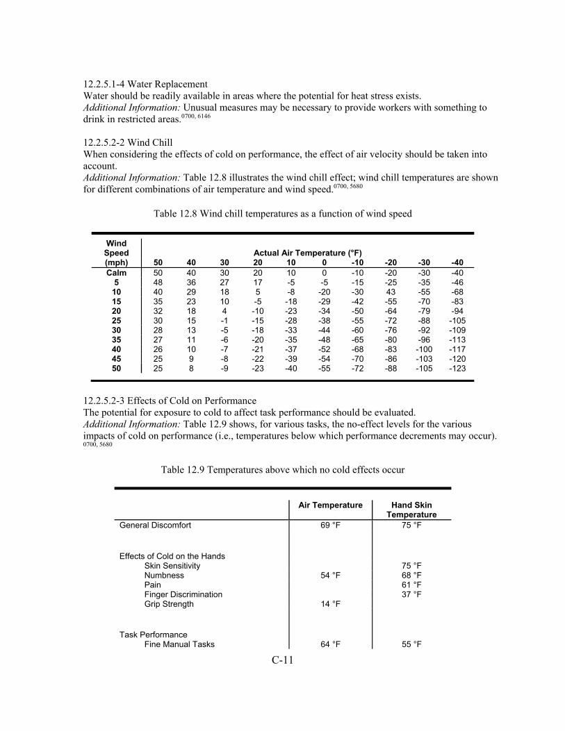
C-11
12.2.5.1-4 Water Replacement Water should be readily available in areas where the potential for heat stress exists. Additional Information: Unusual measures may be necessary to provide workers with something to drink in restricted areas.0700, 6146 12.2.5.2-2 Wind Chill When considering the effects of cold on performance, the effect of air velocity should be taken into account. Additional Information: Table 12.8 illustrates the wind chill effect; wind chill temperatures are shown for different combinations of air temperature and wind speed.0700, 5680
Table 12.8 Wind chill temperatures as a function of wind speed
Wind Speed Actual Air Temperature (°F) (mph) 50 40 30 20 10 0 -10 -20 -30 -40 Calm 50 40 30 20 10 0 -10 -20 -30 -40
5 48 36 27 17 -5 -5 -15 -25 -35 -46 10 40 29 18 5 -8 -20 -30 43 -55 -68 15 35 23 10 -5 -18 -29 -42 -55 -70 -83 20 32 18 4 -10 -23 -34 -50 -64 -79 -94 25 30 15 -1 -15 -28 -38 -55 -72 -88 -105 30 28 13 -5 -18 -33 -44 -60 -76 -92 -109 35 27 11 -6 -20 -35 -48 -65 -80 -96 -113 40 26 10 -7 -21 -37 -52 -68 -83 -100 -117 45 25 9 -8 -22 -39 -54 -70 -86 -103 -120 50 25 8 -9 -23 -40 -55 -72 -88 -105 -123
12.2.5.2-3 Effects of Cold on Performance The potential for exposure to cold to affect task performance should be evaluated. Additional Information: Table 12.9 shows, for various tasks, the no-effect levels for the various impacts of cold on performance (i.e., temperatures below which performance decrements may occur). 0700, 5680
Table 12.9 Temperatures above which no cold effects occur
Air Temperature Hand Skin
Temperature General Discomfort 69 °F 75 °F
Effects of Cold on the Hands
Skin Sensitivity 75 °F Numbness 54 °F 68 °F Pain 61 °F Finger Discrimination 37 °F Grip Strength 14 °F
Task Performance
Fine Manual Tasks 64 °F 55 °F

C-12
Tracking 55 °F Gross Manual Tasks 54 °F 59 °F
12.2.5.2-6 Protective Clothing Insulated clothing, hats and gloves should be provided to workers who are exposed to cold. Additional Information: The need to remove gloves to perform certain tasks should be taken into account, and engineering and administrative controls should be applied accordingly. 0700, 5680 12.2.5.3-6 Auditory Capabilities of Users The hearing sensitivity of the work force should be monitored. Additional Information: The needs of those workers with hearing degradation should be taken into account.0700, 6146
References Federal Aviation Administration (2003). Human Factors Design Standard (HF STD-001). Washington, DC: Federal Aviation Administration. International Organization for Standardization (2005). Ergonomic Design of Control Centers, Part 6: Environmental Requirements for Control Centres (ISO 11064-6:2005). Geneva, Switzerland: International Organization for Standardization (ISO). National Aeronautics and Space Administration (2011). NASA Space Flight Human-System Standard Volume 2: Human Factors, Habitability, and Environmental Health (NASA 3001, Vol. 2). Washington, DC: National Aeronautics and Space Administration. U.S. Department of Defense (2012). Department of Defense Design Criteria Standard: Human Engineering (MIL STD-1472G). Washington DC: U.S. Department of Defense. New Section 14—Degraded HSI and I&C Conditions Integrated digital I&C systems in new reactors will support operators in monitoring and controlling the plants. Even though digital systems typically are highly reliable, they can degrade or fail, which can significantly affect the operators’ performance and, consequently, jeopardize plant safety. We included a new section containing guidance for reviewing the operator’s ability to detect and manage degraded HSI and I&C conditions, such as the degradation of sensors that can complicate the operators’ interpretation of displays by misleading them into thinking that a process disturbance has occurred. The guidance is organized into sections addressing HSIs for monitoring I&C system conditions, HSI responses to I&C system changes, information sources and quality, and backup of HSI and I&C failures. The guidance included in this section is the result of an NRC research project described in The Effects of Degraded Digital Instrumentation and Control Systems on Human-System Interfaces and Operator Performance (O’Hara et al., 2010). The guidance in this technical report was later updated in a report entitled Development of NUREG-0700 Review Guidance for Degraded Human-System Interface, Instrumentation, and Control Conditions (O’Hara and Anderson, 2014). Existing NUREG-0700 guidance on this topic was integrated into the new section. This was done to enhance the visibility of this important topic and to help ensure that it is addressed in all aspects of HSI review.
C-13
In addition to design review guidance, the research identified a number of design process implications. These are included in NUREG-0700, Appendix B, “Design Process Guidelines” (see the description below). Appendix B—Design Process Guidelines Appendix B of NUREG-0700 contains guidance for selected HSI topics that address important considerations in the design of those topics. The guidelines in the main sections of NUREG-0700 address the physical and functional characteristics of HSIs and not the unique design process considerations that may be important. However, in the development of guidelines, we often identify aspects of the design process or training that may be important to consider. Such considerations are not within the scope of the main design review guidelines. Nor are they within the scope of a NUREG-0711 review. While NUREG-0711 does address an applicant’s HFE program and the design process, the review is much more general and does not cover design considerations for specific HSI technologies. Thus, NUREG-0700, Appendix B, fills this gap by identifying important design process considerations that are specific to particular HSI technologies. Nuclear Regulatory Commission reviewers can address the considerations contained in Appendix B on a case-by-case basis during specific reviews. Two new sections were added to Appendix B: • B.4, “Review Guidelines for the Automation System Design Process” • B.5, “Review Guidance for Degraded HSI and I&C Conditions Design Process” Section B.4, “Review Guidelines for the Automation System Design Process,” is organized according to design process topics such as operating experience review and function allocation, like NUREG-0711. Within these topics, considerations are presented on high-level goals of automation design, automation design characteristics, HSI design, training for automation use and degradation, and test and evaluation. Section B.5, “Review Guidance for Degraded HSI and I&C Conditions Design Process,” is similarly organized using NUREG-0711 topics. Within these topics, considerations are presented on understanding the systems failure modes and their effects on human performance, describing task requirements for managing HFE-significant HSI and I&C degradations, and identifying which degradations affect important human actions. In addition to these two new sections, several guidelines related to degraded conditions were deleted because there is a new section specifically addressing this topic. General Changes to NUREG-0700 Topic Characterizations Each section of guidelines begins with a topic characterization. The characterization describes the design aspects of the HSI topic that are important to human performance. The characterization has to be sufficiently robust to accommodate the review of a diversity of designs that designers may employ. Characterizations are important because they provide a structure for developing and organizing the guidance. Also, they give the reviewer a framework for performing design safety reviews. Consistency was added to these characterizations by grouping them according to the organization of the guidelines themselves.

C-14
Bibliographies We added a “Bibliography” to the Characterization sections. The bibliography is divided into two sections: “Source Code Documents,” and “Other References.” The source code documents are those documents identified as the basis of individual guidelines. Users can find the full references to those codes in the Source Code Documents subsection of the Bibliography. The “Other References” section contains the full references to any other documents cited in the “Characterization,” or in the “Additional Information,” parts of the guidelines. NUREG-0700, Rev. 2, only provided references to source code documents, which was located in the Preface, rather than to the particular sections in which they apply. Cross-References We increased the use of cross-references to supporting guidance. Reviewers can consult the cross-referenced guidance to obtain additional information. Appendix D—Glossary Appendix B of NUREG-0700 contains guidance for selected HSI topics that address important considerations in the design of those topics. Index We removed the index. The index had limited value, in part, because of the number of times common terms are repeated. Few standards and guidance documents have indexes for this reason. NUREG-0700 has a detailed organizational structure, and users are better served finding needed guidance accessing it through the detailed contents.

D-1
APPENDIX D: GLOSSARY Abbreviation—A shortened form of a word or phrase used for brevity. Acknowledgment—The feedback to the sender that a message has been received. Acronym—A word formed from the initial letter(s) of each of the successive or major parts of a compound term. Action sequence—A set of operations that must be performed sequentially to carry out a control action. Activated alarm—The condition in which a monitored parameter exceeds a specified limit (setpoint), the deviation is evaluated by the processing portion of the alarm system, and a message is conveyed to the operator through the display portion of the alarm system (e.g., annunciators). Active window—The window in which the user is currently interacting with the system. Typically, this means that an active window (a) is currently receiving input from the user, (b) has last received input from the user, or (c) has been readied for input through the user’s explicit action. The user is generally said to be “working in” the active window (such as processing a document, controlling a system, entering data). (See also inactive and closed windows). Additive color process—The presentation of color images by the simultaneous selective projection of red, green, and blue light on a screen. Addressing messages—The act of preparing header information to specify the destination for transmitting data. Advanced alarm system—A primarily digital alarm system employing alarm processing logic and advanced control (e.g., onscreen controls) and display (e.g., video display unit (VDU)) technology. (This is in contrast to conventional alarm systems, which are largely based on analog instrument and control technologies.) Advanced control room (ACR)—A control room that is primarily based on digital technology. ACRs typically allow the operator to interact with the plant through computer-based interfaces, such as VDUs. This is in contrast to “conventional” control rooms, which provide interaction through analog interfaces, such as gauges. Adjustment controls—The controls used by personnel to correct or adjust the operation of equipment, such as to set an operating value. These controls may be external, such as controls mounted on maintenance panels, or internal, such as test and relay switches located on printed circuit boards. Agent—An entity that performs a task (e.g., an operator or an automatic system). Alarm—The term alarm used in the broad sense (i.e., a plant parameter, component, system, or function that is currently in a state requiring the attention of plant personnel). For example, a monitored parameter exceeds a specified limit (setpoint), the deviation is evaluated by the processing portion of the alarm system, and a message is conveyed to the operator through the display portion of the alarm system.
D-2
Alarm acknowledge—An alarm control function used to change the alarm’s coding from that indicating an unacknowledged alarm visual and audible alert state to an acknowledged, not cleared, state. Alarm availability—The display processing method by which the results of alarm processing are made available to the operating crew. This relates to which alarms are made available to the operator rather than how they are presented (which is referred to as alarm display). Three techniques are identified: filtering, suppression, and prioritization. Alarm coding—The method of highlighting an alarm display visually or audibly to draw the operator’s attention to the display and communicate information about the alarm. Alarm control—The alarm control functions needed by operators, such as silence, acknowledgement, reset, and test (SART). In addition to the basic SART controls, newer alarm systems provide many and varied alarm management functions. Alarm display—The method(s) by which alarm coding and messages are presented to plant personnel. Alarm dynamic prioritization—The alarm processing that dynamically changes an alarm’s priority based on plant conditions at the time of the alarm, existence of other alarms, and the order in which the alarms occur. Alarm filtering—An alarm display processing technique that may eliminate alarm messages that are irrelevant, less important, or otherwise unnecessary. These alarm messages are not available to the operators. (This is in contrast to suppression, which does not make the alarm messages immediately available but does allow the operator to retrieve them.) Alarm generation processing—A class of alarm processing that includes techniques that analyze the existing alarms, and then based upon this, generate alarm messages that (1) give the operator higher level or combined information, (2) notify the operator when “unexpected” alarms occur, or (3) notify the operator when “expected” alarms do not occur. Alarm legend—The caption identifying an alarm. Alarm message—Information presented to the operator by the auditory, visual, and other display devices of the alarm system in response to an alarm condition. Alarm prioritization—The categorizing of alarms according to their relative importance. Importance is determined by considerations including the associated consequences to plant safety and need for operator action. The priority may be fixed by static priority or determined dynamically from considerations that include plant conditions. Alarm processing—Alarm signal processing functions, rules, or algorithms used to determine the operational importance and relevance of alarm conditions, determining whether the alarm messages that are associated with these conditions should be presented to the operator. The alarm condition processing includes four classes of processing techniques: Nuisance Alarm Processing, Redundant Alarm Processing, Significance Processing, and Alarm Generation Processing. Alarm processing techniques—The rules or algorithms that are used to analyze plant sensor data to determine their importance, validity, and relevance, and determine whether an alarm message should be presented to the operator.

D-3
Alarm recording—The method ensuring that the identity and time of appearance and clearing of each alarm and alarm signal is permanently available for offline study and analysis, using a permanent record such as a printout or long-term magnetic or optical recording. Alarm reduction—The term for reducing the number of alarms by alarm processing techniques to support the crew’s ability to detect, understand, and act upon all important alarms in a timely manner. See alarm processing. Alarm reset—An alarm control function used to place the alarm in an unalarmed state after the initiating deviation has cleared. Alarm routing—The act of sending an alarm to the workstation or location based on who should respond to it. Alarm signal—A binary signal processed to provide an alarm. Alarm signal processing—The process by which signals from plant sensors are automatically evaluated. This process, which includes signal validation and other techniques, determines whether an alarm condition exists. Alarm signal validation—See signal validation. Note: the definition of signal validation has been updated and is in the report on new guidance for degraded human-system interfaces (HSIs) and instrumentation and control (I&C) conditions. Alarm silence—An alarm control function used to stop the auditory alert signal associated with an alarm. Global silence stops all active auditory alert signals. Alarm static prioritization—An alarm priority determination performed in advance. Engineering and operational analysis determines which alarms are most important and which are lower priority. The coding applies to all anticipated operating modes. Alarm suppression—A class of alarm display processing by which alarms determined by processing techniques to be less important, irrelevant, or otherwise unnecessary are not presented to the operators but can be accessed by operators upon request. This approach is intended to help the operators focus attention on the most important alarm conditions when multiple alarm conditions exist. Alarm system—An automated system consisting of processing and display hardware and software, which processes or analyzes signals from plant sensors and alerts the operator through visual or auditory displays, or both, when monitored parameters deviate from specified limits (setpoints) or predefined conditions. Alerting—The use of visual and audible signals to draw the operators’ attention. Alphabetic—A character set that contains letters and other symbols, excluding numbers. Alphanumeric—A character set that contains letters, digits, and usually other symbols, such as punctuation marks. Alphanumeric code—A set of letters and/or numbers used to identify a group of data (e.g., in a table).

D-4
Alphanumeric keyboard—A keyboard used for typing letters or numbers into the computer. Analytical redundancy—The calculation of expected parameter values using a model of system performance. For example, “reactor power,” “reactor coolant temperature rise through the reactor core,” and “reactor coolant flow rate” are interrelated parameters based upon the physical principles of heat transfer. A measured value for coolant flow should be consistent with the analytically calculated value for coolant flow determined from the corresponding measured values of reactor power and coolant temperature rise. Annunciator—An indicator of the status of a plant parameter, component, system, or function that does not necessarily require the attention of plant personnel. When such attention is required, an alarm condition exists. The term annunciator is sometimes used to refer to the spatially dedicated display portion of an alarm system. Annunciator tile—An engraved title or legend shown on a tile and lit from behind when its alarm condition is present; also called an alarm tile. Architecture—The organizational structure of a system. Arrow buttons—A pair of buttons used to change a value by increments each time they are pressed. Often, the button that produces an increase is marked with an upward arrow and the button that produces a decrease is marked with a downward arrow. Audio—The acoustic, mechanical, or electrical frequencies corresponding to normally audible sound waves. Auditory—A term denoting the sense of hearing. Automatic mode—A mode in which processing proceeds without human intervention (as contrasted with interactive and manual modes). Automatic, self-correcting features—Features that detect and automatically correct errors that users make when providing inputs. For example, a “Delete” command that is incorrectly entered as “DLE” may be automatically changed to its correct form, “DEL,” and then executed. Automatic test equipment—Test equipment that checks two of more signals in sequence without the intervention of a maintainer. The test usually stops when the first out-of-tolerance signal is detected. Automation—A device or system that accomplishes (partially or fully) a function or task. Automation adaptability—The term for whether automation is designed to always function at the same level or whether the level can change, based on defined triggering conditions, such as operator request, operator state, or plant condition. When tasks can be flexibly performed by human or machine agents, the automation is said to be adaptive. Automation levels—Levels of automation that refer to the extent to which a task is automated, ranging from fully manual, to partially automated, to fully automated.
D-5
Automation modes—Modes that define sets of mutually exclusive behaviors that describe the relationship between input to the automation and the response to it. Automation processes—The processes used by automation to accomplish its tasks, including control algorithms, decision logic (such as the use of Boolean logic), and virtually any other type of information processing routine suited to its tasks. Automation reliability—The probability that a task will be performed correctly. Automation triggering conditions—The conditions that initiate or trigger a change in automation, such as operator request, operator state, or plant condition. Backlash—The failure of the output signal to track a control input as the movement of the control is started or stopped; in mechanical systems, this is also referred to as “play.” Bar chart—A graphic figure in which numeric quantities are represented by the linear extent of parallel lines (or bars). The length of the line (or bar) is proportional to the numbers represented. Bar charts are useful for comparing separate entities or showing a variable sampled at intervals. Bench mockup—An actual unit of equipment or replica used in training for checking or locating faults. Binary—(1) The term for a characteristic or property involving a selection, choice, or condition in which there are two possibilities. (2) Pertaining to the number representation system with two values. Blank—Containing no data, a nonprinting graphic character used to separate data, a space for the entry of data. Buffer—A file or device that temporarily stores data. Built-in test—An integral part of a unit of equipment that performs diagnostic tests. Built-in features may be as simple as a voltmeter or as complex as an automatic checker. Built-in test panel—A panel containing connections for external test devices so that internal components can be assessed. Button—A type of hardware control device or a defined control region on the display screen which, when selected, causes some action. Cancel—A capability that regenerates (or re-initializes) the current display without processing or retaining any changes made by the user. Capture error—An error of execution (slip) that occurs when an infrequently performed action requires a sequence of operations, some of which are the same as or similar to those of a frequently performed action. In attempting the infrequent action, the more frequent action is performed instead. For example, an operator intends to perform task 1, composed of operations A, B, C, and D, but instead executes the more frequently performed task 2, composed of operations A, B, C, and E. Category—A grouping of data values along a dimension defined for operational purposes.
D-6
Cathode ray tube—An electronic vacuum tube, such as a television picture tube, that can be used to display textual information or graphics, or both (typically abbreviated “CRT”). Caution signal—A signal that alerts the operator to an impending condition requiring attention but not necessarily immediate action (see warning signal). Character set—A set of unique representations called characters (e.g., the 26 letters of the English alphabet and the 128 characters of the ASCII alphabet). Character width—The horizontal distance between a character’s origin (a point on the base line used as a reference location) and the next character’s origin. Character—A letter, digit, or other symbol that is used as part of the organization, control, or representation of data. CIE distance—Difference between colors expressed as a distance in the Uniform Color Space established by the Commission Internationale de l'Eclairage (International Commission on Illumination); the three-dimensional color space is based on the response of the human eye to light of different wavelengths. Circuit breakers—Devices that protect equipment from excessive electrical current. Circuit packaging—A method for organizing equipment into modules in which all parts of a single circuit or logically related group of parts, and only that circuit or group, are placed in a separate module. Clear—A system function that removes the current selection but does not put it into the temporary buffer. A copy is retained, accessible immediately by the Undo command. Cleared alarm—An alarmed parameter that has returned from an alarmed state to its normal range. Some alarm systems generate alarm messages when the parameter enters the normal range. The operator may be required to reset the alarm to “clear” it. Click—An input device “buttondown” action (e.g., depressing and releasing the button on a mouse or trackball) for the actual entry (enabling, activation) at a designated position. This action is distinct from cursor positioning. Also, the auditory feedback from keyboard entry. Closed window—A window that is not visible and that requires some action by the user to gain perceptual and functional access. For example, a user may select and open an icon that represents a window or, in contrast, might input a command to open a specific window. (See also active and inactive windows.) Coding—The use of a system of symbols, shapes, colors, or other variable sensory stimuli to represent specific information. Coding may be used (a) for highlighting (i.e., to attract a user’s attention to part of a display), (b) as a perceptual indicator of a data group, or (c) to symbolize a state or attribute of an object (e.g., to show a temperature level or for warning purposes). Coherence mapping—A map between the features in the representation and the physical and cognitive characteristics of the operator (how comprehensible the representation is to the operator).

D-7
Collating test equipment—Test equipment that presents the combined results of two or more checks. For example, a light might come on only if a number of different signals are all within tolerance. Color—The aspect of objects or light sources that may be described in terms of hue, lightness (or brightness), and saturation. Column—A vertical arrangement of items. Command—(1) The act of instructing the computer or system to perform an action. (2) An entry provided by a user, which instructs the computer system to perform an action. Command language—A type of dialogue in which a user composes entries, possibly with minimal prompting by the computer. Communication systems—Systems that support communications, such as between personnel in the main control room, between the main control room and local sites within the plant, and across sites within the plant. The broad variety of communications media may be generally categorized as speech-based and computer-based systems. Component—A term with several meanings, depending on its context. In the context of the entire plant, a component is an individual piece of equipment, such as a pump, valve, or vessel, and is usually part of a plant system. In a human-system interface context, a component is one part of a larger unit, such as one meter in a control board. In a maintenance context, a component is a subdivision of a unit of equipment that can be treated as an object by the maintainer but that can be further broken down into parts. A mounting board together with its mounted parts is an example of a component. Component packaging—A method for organizing equipment into modules in which similar parts or components are located together; for example, all the fuses or all the relays might be grouped together. Computer-based procedure systems—Systems that present plant procedures in computer-based, rather than paper-based formats. Computerized operator support systems—Systems that use computer technology to support operators or maintenance personnel in situation assessment and response planning. They can monitor status and provide recommendations or warnings. Concatenation—(1) The process of linking data together. (2) A set of logically related items that are treated as a whole. Configural display—A display in which information dimensions are uniquely represented but where new emergent properties are created from interactions between the dimensions. Configural display representations often use simple graphic forms, such as a polygon. Confirmation step—A step in a transaction sequence that requires the user to respond to a warning or advisory message. For example, the user may respond to the question, “Are you sure you want to do this?” by pressing “Yes” or “No.” Context definition—An indication of previous user actions or computer processing that will affect the results of current actions, to help a user predict how the system will respond.

D-8
Continuous—An uninterrupted extension in space, time, or sequence; see also discrete. Continuous-adjustment interfaces—Computer-based formats that have continuous ranges, usually accessed with some type of slewing motion requiring a gross movement followed by a fine adjustment. Their operation is similar to that of physical control devices that provide continuous adjustment, such as rotary dials or slider switches. Continuous online self-test—A testing capability that continuously monitors overall system availability by rapidly identifying hardware failures. Contrast—The diversity of adjacent parts in color and intensity. Contrast ratio—The measured luminance at one point divided by the measured luminance at another, equal to Lt/Lb, (Ls-Lb)/Lb, or (1+Ls)/Lb, where
Lt = total luminance, or luminance of the image in the presence of background; Ls = luminance of the symbol without background (luminance emitted by CRT in the case of CRT displays); Lb = luminance of background.
Contrast ratio, rather than contrast, is often specified by display manufacturers because it is numerically larger (by one) than contrast. Control—A mechanism used to regulate or guide the operation of a component, equipment, subsystem, or system. Control entry—User input for sequence control, such as function key activation, menu selection, and command entry. Controlling transmission—The process of saving transmitted data until they can be delivered or returned to the sender. Conventional alarm system—A primarily analog-based alarm system employing little or no alarm display processing logic and using conventional control (e.g., pushbutton) and display (e.g., annunciator tiles) technology. (This is in contrast to advanced alarm systems.) Copy—A system function that puts a duplicate of the selection into the temporary editing buffer without disrupting the original data. Correspondence mapping—A map between the properties and characteristics of the system to be represented and the features in the representation (how well the display communicates meaningful information about the plant to operators). Cross-coupling—A defect of a multiple-axis positioning system whereby an adjustment of one axis causes an undesired change in another. CRT—See “Cathode ray tube.” Cursor—A display graphic that is used to indicate the position of the user’s operation on the display (such as an arrow or flashing bar).

D-9
Cut—A system function that removes the current selection from the screen and puts it into the temporary editing buffer, replacing the buffer’s previous contents. Cut may be used to either delete or to move a selection. Darkboard—An alarm display in which the medium is dark (not illuminated) if all monitored plant parameters are in the normal range. Thus, an illuminated alarm-display device indicates a deviation from normal plant conditions. This is in contrast to many conventional alarm systems, which employ display devices to indicate both normal and abnormal changes in the plant’s condition. Data—The raw materials from which a user extracts information. (A user can be a human or another component of the system, such as an expert system.) Data may include numbers, words, and pictures. Data display—Output of data from a computer to its users. Generally, this phrase denotes visual output, but it may be qualified to indicate a different modality, such as an “auditory display.” Data entry—User input of data for storage in, and/or processing by, the system. Data item—A set of characters of fixed or variable length that forms a single unit of data. Sometimes a data item might contain only a single character. Data items may be entered by a user or may be displayed by the system. Data protection—Functional capabilities that guard against unauthorized access to and tampering with data and data loss caused by user errors or computer failure. Data transmission—Computer-mediated communication among system users, as well as with other systems. Data validation—A process by which data are checked for accuracy by comparing values from redundant sources (e.g., automated comparison of data from redundant sensors). Database—A structured set of data, manipulated using a data management system. Deemphasis—The inverse of preemphasis, employed for the purposes of restoring original vowel-consonant amplitude relationships in preemphasis speech; primarily useful in maintaining the “natural” sound quality. Decibel (dBA)—Sound level in decibels, measured using A-weighting. The use of A-weighting causes the frequency response of the sound level meter to mimic that of the human ear (i.e., response is maximum at about 2 kilohertz (kHz), less at very low or very high frequencies). A-weighted measurements correlate well with measures of speech interference and judgments of loudness. Default—A “typical” or “safe” value or setting that is used if no alternative is specified; the value assumed unless specifically overridden. Defaults represent predetermined, frequently used values for data or control entries intended to reduce entry actions required from the user. Degraded condition—A state in which a system or component operates at less than its fully intended function, including failure. Demarcation—The technique of enclosing functional or selected groups of controls and displays with a contrasting line to emphasize their relatedness.

D-10
Density—(Screen Density) The amount of the display screen that contains information, often expressed as a percentage of the total area. Derived information—Displayed information that could be based directly on sensor measurement but instead is derived from the measurements of other sensors. For example, the flow into a tank might not be directly sensed but can be assessed from a change in level over time. (See also directly-sensed and synthetic information.) Description error—An error of execution (slip) that involves performing the wrong set of well-practiced actions for the situation. Description errors occur when the information that activates or triggers the action is either ambiguous or undetected. Diagram—A special form of a picture in which details are only shown if they are necessary to perform a task. For example, an electrical wiring diagram for a facility would show wiring but not necessarily furniture or plumbing. Dialogue—A structured series of interchanges between a user and a computer. A dialogue can be initiated by a computer (e.g., question and answer) or by a user (e.g., command language). Digitizing tablet—A (graphics tablet) device used to convert an image into a digital code drawing or tracing with a penlike or pucklike instrument. The instrument is moved across the tablet and a series of X-Y coordinates is generated. Dimension—A scale or categorization along which data may vary, taking different values at different times. Direct manipulation—The user manipulates symbols in the display by directly interacting with the symbol. The direct manipulation is generally performed by using a display structure, such as a pointer, and a cursor control device, such as a mouse. Directly sensed information—Information that is derived from a sensor measurement (e.g., the flow out of a tank based on a flow sensor in the output pipe. (See also derived and synthetic information.) Derived information—Information that could come directly from a sensor measurement but instead is derived from the measurements of other sensors; for example, the flow into a tank that is derived from the change in level over time, rather than a flow sensor. (See also directly sensed and synthetic information.) Discrete—Distinct or unconnected elements; see also continuous. Discrete-adjustment interfaces—Computer-based formats with individual settings that usually can be accessed using fairly gross movements. Their operation is similar to discrete-adjustment controls, such as pushbuttons. Display—A specific integrated, organized set of information. A display can be an integration of several display formats (such as a system mimic, which includes bar charts, trend graphs, and data fields). Display control—Procedures by which a user can specify what and how data are shown.

D-11
Display device—The hardware used to present the display to users. Examples include VDUs and speakers for system messages. Display element—A basic component used to make up display formats, such as abbreviations, labels, icons, symbols, coding, and highlighting. Display format—The general class of information presentation. Examples of general classes are continuous text (such as a procedure display), mimics, and piping and instrumentation diagram (P&ID) displays, trend graphs, and flowcharts. Display network—A group of display pages within an information system and their organizational structure. Display page—A defined set of information that is intended to be displayed as a single unit. Typical nuclear power plant display pages may combine several different formats on a single VDU screen, such as putting bar charts and digital displays in a graphic P&ID format. Display pages typically have a label and designation within the computer system so they can be assessed by operators as a single “display.” Display selection—The specification of data outputs, either by a user or automatically. Display structure—Functional or information-presenting aspects of a display that are consistent in appearance and are used across applications (e.g., providing reference to the user’s location in an information system and display of control options available). Display tailoring—Designing displays to meet the specific task needs of a user rather than providing a general display that can be used for many purposes. Dot matrix—A rectangular array of dots or lights from which characters are built. Drag—The act of moving a follower (such as a cursor) or selected icon through parts of a display (typically using a direct manipulation device such as a mouse). Dynamic—The term for being marked by continuous activity or change. Dynamic display—A display containing screen structures that change one or more feature(s) (e.g., numeric value, color, shape, or spatial location, in real time or near real time). Emergent feature—A high-level, global perceptual feature produced by the interactions among individual parts or graphic elements of a display (e.g., lines, contours, and shapes). Enter—An explicit user action that affects computer processing of user entries. For example, after typing a series of numbers, a user might press an ENTER key that will add them to a database, subject to data validation. Enter key—The key used to indicate the completion of data entry for a current field or record. Entry—(1) The act of putting information into the system, and (2) something that has been entered, such as data or a command. Equipment packaging—The way that modules, components, and parts are arranged within an enclosure.

D-12
Excerpt file—A file that allows the user to move data from one location to another; it differs from a temporary editing buffer in that the excerpt file can be saved. Data can be appended to or interleaved into the existing contents of the excerpt file. Existing alarm—An acknowledged alarm that has not yet cleared. Extinguished alarm (also called reset alarm)—An alarm that has returned to an inactive state (e.g., the plant parameter has returned to the normal range and all associated alarm messages have been acknowledged by the operator). Failure—The inability of a system or component to perform its function. Fault tolerance—The existence of redundancy or diversity with fault-detection capability. Continuity of operations is ensured by providing the needed function using a capability that is fault free. Fault-tolerant digital control systems—Digital systems with redundant processors that use fault-diagnostic routines that can detect single faults and isolate the failed equipment. This helps to verify that the equipment that is still operational takes over the control function. Feedback—A system or component response (e.g., visual or aural) that indicates the extent to which the user’s desired effect was accomplished. Feedback can be either intrinsic or extrinsic. Intrinsic feedback is that which the individual senses directly from the operation of the control devices (e.g., clicks, resistance, control displacement). Extrinsic feedback is that which is sensed from an external source that indicates the consequences of the control action (e.g., indicator lights, display changes, aural tones). Field—An area of the display screen reserved for the display of data or for user entry of a data item. In a database, it is a specified area used for a particular category of data; for example, equipment operational status. Field label—A displayed word or phrase that identifies the data display or entry field. File—A collection of data that is treated as a single unit (e.g., such as that stored in the computer). First-out alarm—An alarm message that indicates the initial change in parameter responsible for reactor or turbine trips. Fixed form—A term referring to a mode of input in which the user is presented with a set of blanks to be filled in. Fixed format—An unchanging description of specified information content in a particular area. Fixed function key—A key having a function that cannot be changed by the user or system and that remains constant between applications. Flowchart—A diagram that illustrates sequential relations among elements or events. Flowcharts are often shown as boxes connected by arrows. Follower—The onscreen symbol (such as a cursor and arrow pointer) that responds to the movement of computer input devices (such as a cursor key, mouse, trackball, or light pen).

D-13
Form—A dialogue technique that presents category labels and requires the user to fill in the blanks; a formatted output to the user with blank spaces for inserting required or requested information. Format—The arrangement of data. Formatting—The process or act of arranging data. Frequency modulation—The sinusoidal variation of the frequency of a tone around a center frequency. Frequency—The rate of signal oscillation in cycles per second (hertz (Hz)). Function—(1) A software-supported capability provided to a user to aid in performing a task. (2) A process or activity that is required to achieve a desired goal; see, for example, safety function. Function allocation—The process of assigning responsibility for function accomplishment to human or machine resources or to a combination of human and machine resources. Function analysis—The examination of system goals to determine what functions are needed to achieve them. Function areas—The specific screen or panel locations that are reserved for specific purposes. Function key—A key the activation of which will affect a control entry. Detection of the signal usually causes the system to perform some predefined function for the user. Fuses—Devices that protect equipment from changes in electrical current. Gloss—The extent to which light incident on a surface at angle x is reflected from that surface at angle -x (minus x) relative to a line perpendicular to the surface. A mirror has maximum gloss. Gloss instrument—A device that measures reflected light as a function of illumination and angle of view. The angle for which gloss is measured is typically 60 degrees. Go/no-go test equipment—Test equipment that provides one of two alternative answers to any question. For example, it may give a qualitative assessment of the condition of equipment by indicating whether a given signal is in (go) or out (no-go) of tolerance. Graph—A display that represents the variation of a variable in comparison with that of one or more other variables. Graphic element—A component part of a graphic display, such as a line, a circle, or a scale. Graphic interaction—A dialogue in which the user selects displayed control elements by pointing or by other direct manipulation. Graphic display—A display that provides a pictorial representation of an object or a set of data. Graphic displays include line, solid object, and perspective drawings; bar, pie, and line charts and graphs; scatterplots; displayed meters; flowcharts and schematic diagrams.
D-14
Graphics—Data specially formatted to show spatial, temporal, or other relations among data sets. Graphics tablet—(Digitizing Tablet) A device used to convert an image into digital code by drawing or tracing with a penlike or pucklike instrument. The instrument is moved across the tablet, generating a series of X-Y coordinates. Grid—A network of uniformly spaced horizontal and vertical lines for locating points by means of coordinates. Group—A set of items. Grouping—(1) The act of locating alarm messages that are related to a common function or system in one area of a display. (2) The act or process of combining in groups. Hardcopy—A printed copy of computer output in a readable form; for example, the printed process displays an alarm listing. Help—Information provided to guide the user in operating the system or displayed at the user’s request for online guidance. Hierarchic branching—A method of structuring menu items that are hierarchically related, which allows selection among alternatives without requiring the opening and closing of a series of menus; the entire hierarchy is contained in one menu. Hierarchy—The designated order or rank of items; a series of items that are classified by rank or order. Highlight—A means of directing the user’s attention to a feature of the display. Highlighting methods include image reversal (reverse video), brightness or boldness contrast, color, underlining, blinking, flashing arrows, and changes in font. Emphasizing displayed data or format features in some way (e.g., by using underlining, bold, or inverse video). Histogram—A type of bar chart used to depict the frequency distribution for a continuous variable. The variable may be grouped into classes. Human engineering discrepancy (HED)—A departure from some benchmark of system design suitability for the roles and capabilities of the human operator. This may include a deviation from a standard or convention of human engineering practice, an operator preference or need, or an instrument or equipment characteristic that is implicitly or explicitly required for an operator’s task but is not provided to the operator. Human factors—A body of scientific facts about human characteristics. The term covers all biomedical, psychological, and psychosocial considerations; it includes, but is not limited to, principles and applications in the areas of human factors engineering (HFE), personnel selection, training, job performance aids, and human performance evaluation (see human factors engineering). Human factors engineering (HFE)—The application of knowledge about human capabilities and limitations to plants, systems, and equipment design. HFE ensures that the plant, system, or equipment design, human tasks, and work environment are compatible with the sensory, perceptual, cognitive, and physical attributes of the personnel who operate, maintain, and support it (see human factors).

D-15
Human reliability analysis (HRA) —A structured approach used to identify potential human failure events (events that represents a failure or unavailability of a component, system, or function that is caused by human inaction, or inappropriate action) and to systematically estimate the probability of those events using data, models, or expert judgment. HFE-significant I&C degradations—The failure modes and degraded conditions of the I&C system that have the potential to affect HSIs used by personnel in performing important human actions (a definition of “important human actions” is provided in this glossary). Human-system interface (HSI)—The human-system interface (HSI) is that part of the system through which personnel interact to perform their functions and tasks. In this document, “system” refers to a nuclear power plant. Major HSIs include alarms, information displays, controls, and procedures. Use of HSIs can be influenced directly by factors such as (1) the organization of HSIs into workstations (e.g., consoles and panels), (2) the arrangement of workstations and supporting equipment into facilities, such as a main control room, remote shutdown station, local control station, technical support center, and emergency operations facility, and (3) the environmental conditions in which the HSIs are used, including temperature, humidity, ventilation, illumination, and noise. HSI use can also be affected indirectly by other aspects of plant design and operation, such as crew training, shift schedules, work practices, and management and organizational factors. Hypertext—A type of link on a display that causes a new display to load when the user clicks on it. Icon—The pictorial, pictographic, or other nonverbal representation of objects or actions. Identification—A code number or code name that uniquely identifies a record, block, tile, or other unit of information. Identifier—A symbol whose purpose is to identify, indicate, or name a body of data. Important human actions— Important HAs consist of those actions that meet either risk or deterministic criteria. • Risk-important human actions—Actions defined by risk criteria that plant personnel use to ensure
the plant’s safety. There are absolute and relative criteria for defining risk-important actions. For absolute ones, a risk-important action is any action the successful performance of which is needed to reasonably ensure that predefined risk criteria are met. For relative criteria, the risk-important actions are defined as those with the greatest risk compared to all human actions. The identifications can be made quantitatively from risk analyses, and qualitatively from various criteria, such as concerns about task performance based on considering performance-shaping factors.
• Deterministically identified important human actions—Deterministic engineering analyses
typically are completed as part of the suite of analyses in the final safety analysis report or design control document in Chapters 7, “Instrumentation & Controls,” and 15, “Transient and Accident Analyses.” These deterministic analyses also often credit human actions.
Inactive window—Windows perceptually and functionally available to the user (the user may be able to see and obtain information from them) but not immediately available in the sense that the user must activate an inactive window before working in it. (See also active and closed windows.)

D-16
Index—To prepare an ordered reference list. An ordered reference list gives the contents of a file or document, together with keys or reference notations to identify or locate those contents. Information—Organized data that users need to successfully perform their tasks. Information can include (a) a representation of facts, concepts, or instructions in a formalized manner suitable for communication, interpretation, or processing by humans or automatic means, and (b) any representations, such as characters or analog quantities, to which meaning is, or might be, assigned. Information system—Those aspects of the HSI that provide information on the plant’s processes and systems to the operator. Initiating transmission—The process of actually sending a command, message, or data file. Transmission can either be initiated by the computer or by a system user. Input—(1) Information entered into a system for processing. (2) The process of entering information. (3) Pertaining to the devices that enter information. Input/output—(1) A term pertaining to either input or output, or both. (2) A general term for the equipment used to communicate with a computer, commonly called I/O. (3) The data involved in such communication. (4) The media carrying the data for input and output. Insert mode—A data entry mode that allows the user to insert new information within existing information. If the cursor is placed within existing information, old characters are moved forward to allow insertion of the new characters. Instrument cabinets and racks—Enclosures that hold modules, components, and parts. They typically have access doors or removable panels for access to their contents. Integral display—A display that depicts the integration of information in such a way that the individual parameters used to generate the display are not explicitly represented in it. Interactive graphics—A mode of input in which the user is graphically (e.g., by plot, histogram) presented data from which to choose. Once an input has been so selected, the user may interact with the system to correct or refine the data. Interactive mode—A processing mode in which the user is assumed to be available to the system for inputs or decision making. The user submits one input at a time to the system, and each input is processed by the system as soon as possible (as contrasted with manual and automatic modes). Interface—(1) The point at which a user and the system interact. (2) A shared boundary (e.g., a hardware component to link two devices or a portion of storage or registers accessed by two or more computer programs). Interrupt—Stopping an ongoing transaction to redirect the course of the processing. Examples of interrupt options are BACKUP, CANCEL, RESTART. Input field—The area in a display that is used to enter input. For example, a soft control may have an area in which operators can enter numeric data to adjust control setpoints or commands to execute actions.

D-17
Interface management—Actions performed by the operator to control the HSI rather than the plant, including finding and retrieving displays and adjusting display windows. Operators typically navigate through displays and retrieve needed controls and displays. Interlock—A feature that requires operator actions to proceed in a specific sequence; for example, action B must be performed after action A, and action C after action B. Joystick—A sticklike control device that can provide continuous cursor control in any direction on a display screen. Justification—The act of adjusting, arranging, or shifting digits to the left, right, or center to fit a prescribed pattern. Keystroke—The act of striking a key. Keystroke command—A single or limited number of keystrokes that define a command. The keystrokes are often initiated by simultaneously pressing a key that signals a keystroke command and the first letter of a one-word command. Another version of the keystroke command is the function key. Keyword—A word exemplifying the meaning or value of the data: (a) one of the significant, informative words in a title or document that describes the content of that document, (b) a symbol that identifies a parameter, or (c) a part of a command operand that consists of a specific character string. Label—A descriptor that is distinguishable from, and helps to identify, displayed screen structures or components. Labeling and marking—The use of labels and demarcations to identify units of equipment, modules, components, and parts. Large-screen display—A large display that can be viewed from multiple workstations and locations in a control room. It typically contains important information that should be commonly available to control room crew members. Layered windows—Layered windows (in contrast to tiled windows) refer to the onscreen positioning of multiple windows so that windows can overlap, possibly obscuring the contents of the covered windows. Layout—The physical arrangement of the parts and components that make up a module or a unit of equipment. Left justified—(1) The left-hand digit or character (or its sign) that occupies the left-hand position of the space allotted for displaying it. (2) Alignment of text along the left margin, leaving the ends of the lines “ragged” on the right side. Legend—(1) The textual content of a continuously present, spatially dedicated alarm display. (2) An explanatory list of symbols or highlighting used on a graph, chart, diagram, or map. Legibility—The quality of a display that allows groups of characters and symbols to be easily distinguishable and recognized.

D-18
Level of abstraction—A hierarchy consisting of levels increasing in abstraction: • physical form—the appearance and spatial location of the components
• physical function—the characteristics of the components and their interconnections
• generalized function—the basic functions a system was designed to achieve
• abstract function—the causal structure of the process in terms of mass, energy, information, or
value flows
• functional purpose—the purpose for which the system was designed; the functional characteristics of the plant as opposed to physical characteristics
Light pen—A control device resembling a pencil or pen that interacts with the computer system through the display device screen either by emitting or sensing light. Local control station (LCS)—An operator interface related to process control that is not located in the main control room. This includes multifunction panels, as well as single-function LCSs, such as controls (e.g., valves, switches, and breakers) and displays (e.g., meters) that are operated or consulted during normal, abnormal, or emergency operations. Location—A position or site occupied or available for occupancy. Lockin—A feature that keeps an ongoing operation active by preventing personnel actions from terminating it prematurely. Lockout—A feature that prevents personnel from providing input that may have negative effects. Statically defined lockouts may restrict operators’ inputs to a specific, predefined range or set of values. Context-sensitive lockouts may restrict input values based on the current situation. Logical flow packaging—A method for organizing equipment into modules in which circuits, parts, and components are packaged and arranged in correspondence with their functional relationships. Loss-of-activation error—An intended action is not carried out because of a failure of memory (i.e., the intention has partially or completely decayed from memory). A special case of loss-of-activation errors involves forgetting part of an intended act while remembering the rest (e.g., retrieving a display while not being able to remember why it is needed). Macro-command—A group of a series of commands redefined as a single command. Main menu—A top-level menu displayed upon entry into the system. Maintainability—The design of equipment to support effective, efficient maintenance activities. Maintenance—A process with the objective of preserving the reliability and safety of plant structures, systems, and components or restoring that reliability when it is degraded. Manual mode—A processing mode in which the user is assumed to provide all inputs (as contrasted with interactive and automatic modes).

D-19
Matte—A surface that scatters incident light nearly equally in all directions; a surface that lacks gloss. May—The word “may” is used to denote permission and applies to a characteristic that is acceptable but not necessarily recommended (e.g., an equally acceptable alternative may exist); see also “should.” Medium—The material, or configuration thereof, on which data are recorded; for example, paper tape, cards, magnetic tape. Menu—A type of dialogue in which a user selects one item out of a list of displayed alternatives. Selection may be made by actions such as pointing and clicking and by depressing an adjacent function key. Menu bar—A specialized function area that displays categories of alternatives for user responses. Menu selection—A type of dialogue in which a user selects one item out of a list of displayed alternatives, whether the selection is by pointing, by entry of an associated option code, or by activating an adjacent function key. Message—(1) Alarm information displayed in text. (2) Data that are transmitted from another user or from the system. Message area—A specialized function area for communication from another user or from the system. Mimic—A display format combining graphics and alphanumerics used to integrate system components into functionally oriented diagrams that reflect the components’ relationships. Mirror-imaging—Symmetrical arrangement of sets of items about an axis such that relationships among things within one set are reversed relative to those in the other set. Misordered components of an action sequence—A human error involving skipped, reversed, or repeated steps. Mistake—An error in intention formation, such as forming one that is not appropriate to the situation. Mistakes are related to incorrectly assessing the situation or inadequately planning a response. Mockup—A static representation of an HSI (see simulator and prototype). Mode—A state of operation in which the system operates in specific, unique ways or has specific, unique characteristics. Mode editor—A text editing system in which the interpretation of the same user input varies depending on whether the system is in entry mode or edit mode. Specifically, in a mode text editor, the user must enter special commands to cause subsequent inputs to be entered either as text or as editing commands. Mode error—Performing an operation that is appropriate for one mode when the device is in another mode. Mode errors occur when the user believes the device is in one mode when it is in another one. Modeless editor—A text-editing system in which the interpretation of the same user input does not vary; ordinary characters are entered as text, and commands are invoked using special keys.

D-20
Modularization—The separation of equipment into physically and functionally distinct units that can be easily removed and replaced. Module—An assemblage of two or more interconnected parts or components that comprise a single physical entry, such as a printed circuit board, with a specific, singular function. Monitor—The physical device housing the electronics, display, and display controls for an interactive computer system (see also “Video display unit”). Mounting—The positioning and attachment of parts, components, and modules. Mouse—A control device where movements across a flat surface are converted into analogous movements of the cursor across the screen. Multitasking—The parallel performance of two or more tasks. N-key rollover—A feature of a keyboard input system that stores keystrokes and generates the corresponding characters in the correct sequence despite more than one key being depressed at the same time (as in very rapid typing). Natural language—A type of dialogue in which users compose control entries in a restricted subset of their natural language (e.g., English). Navigation—A user-interaction function that describes locating the position of desired information and the selection of displays in a VDU-based information system. Non-disruptive—An action that does not interfere with the ongoing activities of the system or user. Nuisance alarm processing—A class of alarm display processing that includes techniques that essentially eliminate alarm messages having no operational significance for current plant conditions. For example, mode-dependent processing eliminates alarms that are irrelevant to the current mode of the plant (e.g., a low-temperature or low-pressure signal that is an alarm condition in normal operation mode but is expected and normal during startup or cold shutdown). Numeric—The term pertaining to numerals or to representation by means of numerals. Object display—A type of integral display that uses a geometric object to represent parameter values graphically but where the individual information dimensions or data contributing to the object are not displayed. Objects—Distinct information whose representation can be displayed or manipulated as a single entity. Objects are normally represented by graphic icons or names, or both. Online maintenance—Maintenance performed while the plant is at power. Open window—Windows that are both perceptually and functionally available to the user. Two types of open windows exist: active and inactive. (See also window.)

D-21
Open/closed—The term for when a window is opened, it appears on the screen. Windows may be closed (removed from the screen) and reopened. Operand—That which is operated upon. Information entered with a request to define the data in which the processor is to operate and control the execution of the processor. Operating experience review—A review of relevant history from the plant’s ongoing collection, analysis, and documentation of operating experiences. Operation—(1) A defined action; namely, the act of obtaining a result from one or more operands in accordance with a rule that completely specifies the result for any permissible combination of operands. (2) The set of such acts specified by such a rule, or the rule by itself. Optical reader—A device that reads handwritten or machine-printed symbols into a computing system. Output—The data that are the product of an information handling operation or series of operations; the data emitted from a storage device; the data being transferred from primary storage (central processing unit) to secondary storage (tape, floppy disk); electrical pulses; reports produced by a printer or typewriter unit; a general term for output media, such as cards and tape (contrasts with Input). Packaging—The grouping of functions, components, and parts into units or modules. Page—(1) The data appearing at one time on a single display screen. (2) A fixed-length block of data, especially that which fits into a printed record or screen. (3) To summon a particular page or the next logical page. Paging—A method of viewing and moving through data in which a user conceives data as being grouped into display-sized pages and moves through them by discrete steps. Also, to summon by calling out by name. Panel—The front face of an assembly, normally used for mounting controls and displays. Parallax—The apparent change in the relative position of objects at different distances from the observer as the observer’s position changes. Parameter—(1) A power-conversion process variable or quantity that can assume any of a given set of physically feasible values. Plant parameters are typically measures of the performance of systems and processes of the plant (e.g., the parameter “T-hot” is a measure of the temperature of reactor coolant that has passed through the reactor core). (2) A variable that is measured. Part—An object that cannot normally be broken down further without destroying its designated use. Fuses, transistors, resistors, and capacitors are examples. Paste—A system function that puts the contents of the temporary editing buffer (a selection previously cut or copied) at the insertion point of the current interactive window. The buffer contents are not altered by this operation. Peak-clipping—A technique for controlling amplitude relationships in speech by limiting the instantaneous peak-amplitudes to improve its intelligibility, usually followed by amplification of the signal to increase the amplitude of the clipped peaks to their original level, with a proportional increase of

D-22
the weaker speech sounds. Performance-based test—A test that involves the measurement of behavior of personnel, the HSI, or aspects of the plant to address design issues and design acceptability. Personal safety—The prevention of individual accidents and injuries of the type regulated by the Occupational Safety and Health Administration. Physically interchangeable units—Units of equipment that can fit into the same mounting position or fixture. Pictographic—Pertaining to a picture-like representation of an object. Pie charts—A circle divided into sections (as pieces of a pie) to represent graphically the relative proportions of different parts of a whole. A circular chart cut by radii into segments illustrating magnitudes or frequencies. Plant—The operating unit of a nuclear power station, including the nuclear steam supply system, turbine, electrical generator, and all associated systems and components. In the case of a multiunit plant, the term plant refers to all systems and processes associated with the unit’s ability to produce electrical power, even though some systems or portions of systems may be shared with the other units. Plant variable—A variable that represents the status of a plant system or process. For example, the variable reactor coolant system pressure represents the pressure inside the piping of the reactor coolant system. (See variable.) Pointing interface—A computer-based user interface operated by cursor or touch screen. Popup menu—A menu whose items are normally “hidden” from the user’s view until they are activated or brought into full view by a complete selection action. Popup menus remain visible until the user takes another action to hide the menu or make a selection. Position—In a string, each location that may be occupied by a character or binary digit and may be identified by a serial number. Position designation—User selection and entry of a position on a display, or of a displayed item. (See also cursor). Preemphasis—Systematic distortion of the speech spectrum to improve intelligibility of the sound by attenuating the low-frequency components of vowels (relatively unimportant for intelligibility) and proportionately increasing the amplitude of high-frequency vowel components and consonants (highly important for intelligible speech transmission). Precision—The degree of discrimination with which a quantity is stated. For example, a three-digit numeral discriminates among 1,000 possibilities. Preparing messages—Includes specification of contents, format, and header information. Primary tasks—Those tasks performed by the operator to supervise the plant (i.e., monitoring, detection, situation assessment, response planning, and response implementation).

D-23
Print queue—An area of computer memory that temporarily stores a file to be printed so that the user can continue interacting with the system while the file prints. Printed circuit board—A module organization in which parts are mounted on an integrated circuit board. Printer—A device that writes output data from a system on paper or other media. Prioritization—A class of alarm-display processing that presents alarm messages to the operator according to an evaluation of importance, often using two-to-four categories of priority. The intent of this approach is to help the operators focus attention on the most important alarm conditions when there are multiple alarm conditions. Processing—The execution of a systematic sequence of operations. Programmable function keys—User-programmable keys whose function may vary between applications or between users within an application. Prompting—The process or act of assisting by suggestion. Prototype—A dynamic representation of an HSI that is not linked to a process model or simulator. A model of an interface that includes the functions and capabilities expected in the final system, although not in a finished form. (See simulator and mockup.) Pulldown menu—A menu whose items are normally hidden from the user’s view and accessed by the user holding the selection button down over the desired menu-bar label. Query language—A type of dialogue in which users compose questions using a special-purpose language to retrieve information. Question and answer—A type of dialogue in which a computer displays questions, one at a time, for a user to answer. Queue—A waiting line or list formed by items in a system waiting for service; for example, tasks to be performed or messages to be transmitted in a message-switching system. Record—A group of related data fields that are operated on as a single entity in a database. Redundancy—In fault tolerance, the presence of auxiliary components in a system to perform the same or similar functions as other components with the purpose of preventing or recovering from failures. Redundant alarm processing—A class of alarm-display processing that includes techniques that evaluate active alarm conditions to identify those that are true or valid but are redundant with other active alarm conditions. This processing filters, suppresses, or reduces the priority of alarm messages that have been determined to be of less importance because they provide information that is redundant with other existing alarm conditions and theoretically provide no new or unique information to the operator. For example, in causal-relationship processing, alarm messages associated with “causes” are displayed prominently, while alarm messages associated with “consequences” are eliminated or lowered in priority.

D-24
Reflash—A method of alarm presentation that can be implemented any time an alarm condition is based on input from more than one plant parameter. Reflash causes an alarm display to reenter the new alarm state when an associated plant parameter reaches its setpoint. The alarm display cannot return to normal until all related parameters return to their normal ranges. Reflectance—The ratio of reflected light to incident light. Rejection level—The minimum level of certainty (represented by a number) required by a speech recognition system for a spoken command to be executed. Remote—Acting on or controlling indirectly from a distance. Request—A user input specifying the operation(s) to be performed. Response time—The time between the submission of an item of work to a computing system and the return of results. Retrace—A capability that returns a user to the last previous display in a defined transaction sequence (also called “backup”). Retrieval—The act, method, or procedure for recovering stored data. Review—In the context of an HSI design, a capability that returns a user to the first display in a defined transaction sequence, while retaining any entries made by the user. Right justified—To adjust the printing positions of characters on a page so that the right margin of the page is regular. To shift the contents of a register so that the least significant digit is at some specified position of the register. Ringback—An alarm display feature that provides a distinct cue, such as a slow flash or audible tone, to indicate that an alarm condition has cleared (i.e., the monitored parameter has returned to its normal range). Row—A horizontal arrangement of characters or other expressions. Rubberbanding—In computer graphics, the continuous stretching, shrinking, or reorientation of connecting lines as a point defining a line or shape is moved. Safety function—Those functions that support higher level objectives, often defined in terms of a boundary or entity that is important to plant integrity and the prevention of the release of radioactive materials. A typical safety function is “reactivity control.” A high-level objective, such as preventing the release of radioactive material to the environment, is one that designers strive to achieve through the design of the plant and that plant operators strive to achieve through proper operation of the plant. The function is often described without reference to specific plant systems and components or the level of human and machine intervention that is needed to carry out this action. Functions are often accomplished through some combination of lower level functions, such as “reactor trip.” The process of manipulating lower level functions to satisfy a higher level function is defined here as a control function. During function allocation, the control function is assigned to human and machine elements.

D-25
Safety goal—A high-level objective such as, “Preventing the release of radioactive material to the environment,” which designers strive to achieve through the design of the plant and which plant operators strive to achieve through its safe operation. Safety related—A term applied to those plant structures, systems, and components that prevent or mitigate the consequences of postulated accidents that could cause undue risk to the health and safety of the public (see Appendix B, “Quality Assurance Criteria for Nuclear Power Plants and Fuel Reprocessing Plants,” to Part 50, “Domestic Licensing of Production and Utilization Facilities,” of Title 10 of the U.S. Code of Federal Regulations). These are the structures, systems, and components on which the design-basis analyses of the safety analysis report are performed. They also must be part of a full quality assurance program in accordance with Appendix B of that document. Scale—A graduated series or scheme of rank or order. Scaling—The positioning of displayed data elements with respect to a defined measurement standard. Scatterplot—A scaled graph that shows relations among individual data points in a 2-dimensional array. Screen—The software-controlled visual interface of a monitor (e.g., the display surface of a CRT). Screen dump—An action, usually performed with a keystroke sequence, that causes the exact contents of the current screen display to be captured for printing or storage in a file. Screen structure—A generic display element, such as a menu bar or title. Scroll—To move data being viewed in a line-by-line manner; to roll upward or downward. Scrolling—An orientation for display framing in which a user conceives of data as moving behind a fixed display frame; the opposite of panning. Secondary tasks—Those tasks that operators perform when interacting with the HSI that are not directed to the primary task. Secondary tasks may include navigating through and paging displays, searching for data, choosing between multiple ways of accomplishing the same task, and making decisions regarding how to configure the interface. Selecting—A user’s action of identifying display elements to the computer to ready them for use in some way (e.g., to open a valve by an input device click on a graphic representation of a valve). Selection display—Any display from which the operator may make a selection, such as choosing a plant variable, plant component, or command. Two formats commonly used for selecting plant components and variables are the menu and mimic. Separable display—A display where each process parameter is presented individually and the representation itself shows no relationships between the parameters. The key aspect of separable displays is not that the individual parameters are presented but that no interaction or relationship between them is perceived. Sequence—An arrangement of items according to a specified set of rules.

D-26
Sequence control—The logic and means by which user’s actions and computer responses are linked to become coherent transactions. Service points—Equipment locations used for performing routine maintenance tasks, such as adjusting, cleaning, or replacing components. Setpoint—The value of a monitored parameter that defines the boundary between the parameter’s normal range and an alarm condition. An alarm condition exists when the parameter exceeds the normal range that is defined by the upper or lower limit setpoints. Graded alarms may have multiple setpoints outside the normal range that produce alarms that indicate increasing levels of severity of the abnormal condition, such as Low Level, or Low-Low Level. Shared (multi-input) alarm—An alarm condition that is defined by the activation of one or more of a set of different process deviations. An example of a shared alarm is a “reactor coolant system trouble” message, which may be displayed when any one of the reactor coolant pumps malfunctions. An individual alarm message associated with the particular malfunctioning reactor coolant pump may also be displayed, in addition to the former message. Should—The word (“should”) used to denote a recommendation; see also “may.” Signal validation—A set of processing techniques by which signals, such as alarm signals, from redundant or functionally related sensors are compared and analyzed to determine whether a true alarm condition exists. The purpose of these techniques is to prevent false alarms being presented to the operator because of malfunctioning plant instrumentation, such as a failed sensor. (Note that this definition modifies the definition in previous NUREG-0700 revisions.) Significance processing—A class of alarm display processing that includes techniques that evaluate active alarm conditions to identify those that are true or valid but are of less operational significance than other active alarm conditions. This processing filters, suppresses, or reduces the priority of alarm messages that have been determined to be of less importance. For example, in an anticipated transient without scram event, alarms associated with minor disturbances on the secondary side of the plant are eliminated or lowered in priority. Simulator—A facility that physically represents the HSI configuration and that dynamically represents the operating characteristics and responses of the plant in real time (see prototype and mockup). Situation awareness—The relationship between the operator’s understanding of the plant’s condition and its actual condition at any given time. Slip—An error in carrying out an intention. Slips result from “automatic” human behavior, when schemas, in the form of subconscious actions that are intended to accomplish the intention, get waylaid en route to execution. Thus, while one action is intended, another is accomplished. An expert’s highly practiced behavior leads to the lack of focused attention that increases the likelihood of some forms of slips. Soft control—A control device that has connections with the control or display system mediated by software rather than direct physical connections. As a result, the functions of a soft control may be variable and context dependent, rather than statically defined. Also, the location of a soft control may be virtual (e.g., within the display system structure) rather than spatially dedicated. Soft controls include devices activated from display devices (e.g., buttons and sliders on touch screens), multifunction control

D-27
devices (e.g., knobs, buttons, keyboard keys, and switches that perform different functions depending upon the current condition of the plant, the control system, or the HSI), and devices activated by voice input. Soft slider—An input format used to directly manipulate a variable over a set range of values (also called a slider bar or a scroll bar). A soft slider resembles a bar chart with a pointer directed toward the current value. They are typically manipulated by pointing interfaces, such as a touch screen or mouse. Input is provided by sliding the pointer along the length of the bar chart scale to the desired value. It is used when the range of possible values and the ratio of a value to the range are displayed. Spacing—The distance between any two objects. Spatially focused, variable location, serial display—A display where alarms are presented in no fixed location and according to some logic, such as time or priority. Usually, the same display device can be used to present many different alarms (in contrast with a spatially dedicated, continuously visible display where a given location presents only one alarm). A scrolling message list is an example of this type of display. Spatially dedicated, continuously visible (SDCV) alarm display—An alarm display that is in a spatially dedicated position and is always visible, whether in an alarmed or cleared state. Conventional alarm tiles are an example of an SDCV alarm display. Specular reflectance—The light incident on a surface at angle x that is reflected at angle – x (minus x). Speech display—Speech messages (either computer generated or a recorded human voice) presented through audio devices, such as speakers and headsets. Speech recognition—A program that permits a user to provide spoken input that a computer interprets as data or commands. Stacked command—A single user input composed of multiple commands that must be executed individually by the computer system. Status information—Information on the state of the system or components (e.g., on/off, open/closed, automatic/manual) that is displayed either automatically or by a user’s request. Status setpoints—Criterion values used in display systems to indicate a change in status of a variable, such as to indicate the approach to an unsafe operating condition. Storage—Any device on which data can be entered, held, and retrieved. The act of storing data on such a device. String—A linear sequence of entities such as characters or physical elements. Stroke width—The width of a line comprising a character. Style guide—A document that contains guidelines that have been tailored so they describe the implementation of HFE guidance to a specific design, such as for a specific plant control room.

D-28
Stylus—A pen-shaped instrument used to “draw” images or point to icons or menu selections. Subsystem—A collection of modules that perform a particular function. Subtractive color process—The presentation of color images by selective absorption of projected light. Symbol—A representation of something by reason of relationship, association, or convention. Syntax—The way in which words are put together to form phrases, clauses, or sentences. Synthetic information—Information that represents higher order information about a plant that cannot be sensed directly but is computed mathematically from data gained from sensors (e.g., rate of change, mass balance). The overall status of a safety function may represent synthetic information based on a computation from the function’s key safety parameters. Any such data used in these calculations from degraded or faulty sensors may propagate to the synthetic variable and distort its meaning (see also directly sensed and derived information). System—An integrated collection of plant components and control elements that operate together, and possibly in conjunction with other systems, to perform a function. System response time—The elapsed time between the initiation of a command and the notification to the user that the command has been completed. System response—The manner in which the computer system behaves after receiving inputs from the user. System security—Features that restrict personnel access to aspects of the computer system to prevent accidental or deliberate damage. Table—A structure of rows and columns consisting of functional areas that contain data and that may or may not require input. Tables may be used to present a variety of types of information. A collection of data in a form suitable for ready reference. Task analysis—A method of detailing the components of a task in terms of the demands placed upon the human operator, the information required by the operator, the extent to which the task requires reliance on or coordination with other personnel, and the relation of the task to other tasks. Task—A series of transactions that comprise part of a user’s defined job. A group of activities that have a common purpose, often occurring in temporal proximity, and that use the same displays and controls. Terminal—An input/output device used to enter and display data. Data are usually entered through a keyboard and are usually displayed on a video screen (soft copy) or by a printer (hard copy). A device, usually equipped with a keyboard and some kind of display, that can send and receive information over a communication channel. Terminology—The technical or special terms of expressions used; nomenclature. Test equipment—Diagnostic tools used to assess the status of equipment and locate faults that may be present.

D-29
Test points—Equipment locations used for conducting tests to determine the operational status of equipment and for isolating malfunctions. Test equipment may be connected at these points. Text—The primary display for word processing, consisting of alphanumeric character strings in linear arrays, that make up words, sentences, and paragraphs. The main body of printed or written matter on a page or in a message. Text entry—The initial entry and subsequent editing of textual data. Tile—A type of SDCV alarm-display that changes state (i.e., brightness, color, or flash rate) to indicate the presence or absence of an alarm condition and that includes text to identify the nature of the alarm state. Tiled windows—Tiled windows (in contrast to layered windows) refers to the onscreen positioning of multiple windows side by side, so that no window overlays information on another. Tiling—A means of manipulating windows by which multiple windows on the same display abut but do not overlap. As the number of windows increases in the tiled window environment, the size of each window decreases. Touch screen—A control device that allows the user to communicate with the computer by touching a screen. Touch zone—An area of a display that a user can activate to perform a predefined operation (e.g., displaying a popup window). Trackball—A control device with which the user can control cursor movement in any direction by rotating a ball. Transaction—An action by a user followed by a response from the computer. Transaction is used here to represent the smallest functional unit of user-system interaction. Transilluminated display—A display having light passed through, rather than reflected off, an element to be viewed (e.g., illumination used on traditional annunciator tile panels or indicators using edge or back lighting techniques on clear, translucent, fluorescent, or sandwich-type plastic materials (in contrast to VDUs). Turnaround time—(1) The elapsed time between submission of a job to a computing center and the return of results. (2) In communications, the actual time required to reverse the direction of transmission from send to receive when using a half-duplex circuit. Unacknowledged alarm—An alarm that has not been acknowledged and displays attention-directing characteristics, such as rapid flashing. Undo—A capability that reverses the effect of the previous operation. Unit of equipment—An assemblage of items that may include modules, components, and parts that are packaged together into a single hardware package.

D-30
Unvalidated data—Data that have not been checked for accuracy. (Unvalidated data may be determined to be either valid or invalid if subjected to a data validation process.) Update—The regeneration of changing data to show current status, by user request or automatically by the computer. User response time—The speed with which a user can enter commands and control a system, regardless of the computer’s ability to quickly process the commands. User-system interaction—The set of methods provided in a computer system through which personnel and the computer communicate with each other. Value—Specified data for a particular parameter or variable. Variable—A quantity that can assume any of the given set of values. Variable function key—A dedicated key that invokes functions of the system; the specific function invoked varies depending, for example, on the mode of operation selected by the user. Verification—The process by which the HSI design is evaluated to determine whether it acceptably satisfies personnel task needs and HFE design guidance. Verification step—A step in a transaction sequence that requires the user to verify an intention to perform a particular action. For example, the user selects an option and then presses the Enter key to verify the selection. Video display unit—An electronic device for the display of visual information in the form of text or graphics; typically abbreviated VDU. Vigilance—The degree to which an operator is alert. Visual angle—A measure, in degrees, of the size of the retinal image subtended by a viewed object. It represents the apparent size of an object based on the relationship between an object’s distance from the viewer and its size (perpendicular to the viewer’s line of sight). An object of constant size will subtend a smaller visual angle as it is moved farther from the viewer. Visual angle is typically defined in terms of minutes of visual arc. Warning signal—A signal that alerts the operator to a condition requiring immediate action (see caution signal). Watchdog timer—An electronic self-testing feature that detects when an expected electrical signal is not received within an expected period, thus indicating a possible malfunction. Window—A geometric area on a computer screen within which the system displays information or receives input from the user. Window overlay—A portion of a display that is temporarily used to show added features, such as requested data, menus, or user guidance, which may obscure previously displayed data. Word—A character string or a bit string considered as an entity.

D-31
Word wrap—The occurrence of words displaced from one line that are moved to the next line so as to maintain the continuity of the text. Workload—The physical and cognitive demands placed on plant personnel. Workstation—The physical console at which a user works.