Embed Size (px)
Citation preview

Human Power Dental Mixer
Preliminary Proposal
By
Mohammad Alenezi
Abdulaziz Alkandary
Fahd Alaskar
Ebraheem Alnafjan
Abdulrahman Alrefaei
Cooper Holden
March 24, 2017
Department of Mechanical Engineering
Northern Arizona University
Flagstaff, AZ 86011
Project Sponsor: Tracye Moore
Faculty Advisor: Sarah Oman
Instructor: Sarah Oman

ii
DISCLAIMER
This report was prepared by students as part of a university course requirement. While considerable effort
has been put into the project, it is not the work of licensed engineers and has not undergone the extensive
verification that is common in the profession. The information, data, conclusions, and content of this
report should not be relied on or utilized without thorough, independent testing and verification.
University faculty members may have been associated with this project as advisors, sponsors, or course
instructors, but as such they are not responsible for the accuracy of results or conclusions.

iii
TABLE OF CONTENTS
DISCLAIMER .............................................................................................................................................. 2 TABLE OF CONTENTS .............................................................................................................................. 3 1 BACKGROUND ................................................................................................................................ 1
1.1 Introduction .............................................................................................................................. 1 1.2 Project Description ................................................................................................................... 1 1.3 Original System ........................................................................................................................ 1
1.3.1 Original System Structure ........................................................................................... 1 1.3.2 Original System Operation .......................................................................................... 2 1.3.3 Original System Performance ..................................................................................... 2 1.3.4 Original System Deficiencies ...................................................................................... 2
2 REQUIREMENTS ............................................................................................................................. 2 2.1 Customer Requirements (CRs) ................................................................................................. 2 2.2 Engineering Requirements (ERs) ............................................................................................. 2 2.3 House of Quality (HoQ) ........................................................................................................... 3
3 EXISTING DESIGNS ........................................................................................................................ 3 3.1 Design Research ....................................................................................................................... 3 3.2 System Level ............................................................................................................................ 3
3.2.1 Existing Design #1: GC Capsule Mixer CM-II ........................................................... 4 3.2.2 Existing Design #2: Capsule Mixer ............................................................................ 4 3.2.3 Existing Design #3: ProMix ........................................................................................ 4
3.3 Subsystem Level ....................................................................................................................... 4 3.3.1 Subsystem #1: Power Input Method ........................................................................... 4 3.3.2 Existing Design #1: Power Use and Transfer ............................................................. 5 3.3.3 Existing Design #2: Method for Shaking Capsule ...................................................... 5
3.4 Functional Model ...................................................................................................................... 5 3.5 Black Box Model ...................................................................................................................... 6
4 DESIGNS CONSIDERED ................................................................................................................. 6 4.1.1 Design #1: Gear Box ................................................................................................... 6 4.1.2 Design #2: Wind Up Spring ........................................................................................ 7 4.1.3 Design #3 Pull-Cord and Flywheel ............................................................................. 7 4.1.4 Design #4 Double handled Gear box .......................................................................... 7 4.1.5 Design #5 Battery powered triturator .......................................................................... 7 4.1.6 Design #6 Bicycle Driven ........................................................................................... 7 4.1.7 Design # 7 Solar Power System .................................................................................. 8 4.1.8 Design #8 Rumble Motors .......................................................................................... 8 4.1.9 Design #9 Rechargeable Batteries .............................................................................. 8 4.1.10 Design#10 pressurized air tube ............................................................................... 8
5 DESIGN SELECTED ......................................................................................................................... 8 5.1 Pull-Chord and Flywheel .......................................................................................................... 9
5.1.1 Rechargeable Batteries ................................................................................................ 9 6 REFERENCES ................................................................................................................................. 10 7 APPENDICES .................................................................................................................................. 11
7.1 Appendix A (Client Approvel) ................................................................................................ 11 7.2 Appendix B (HoQ) ................................................................................................................. 12 7.3 Appendix C: Design Sketches ................................................................................................ 13
7.3.1 Gear Box ................................................................................................................... 13 7.3.2 Wind up Spring ......................................................................................................... 13 7.3.3 Pull-Chord and Flywheel .......................................................................................... 13 7.3.4 Double Handled Gearbox .......................................................................................... 14

iv
7.3.5 Battery Powered Triturator ........................................................................................ 14 7.3.6 Bicycle Driven .......................................................................................................... 14 7.3.7 Solar Power System .................................................................................................. 15 7.3.8 Rumble Motors ......................................................................................................... 15 7.3.9 Rechargeable batteries .............................................................................................. 16 7.3.10 Pressurized Air Tube ............................................................................................. 16
7.4 APPINDIX D (Pugh Chart) .................................................................................................... 17

1
1 BACKGROUND
1.1 Introduction
Many of the places in developing countries are not connected to the electricity grid. Following the
challenges posed by lack of electricity in all these places during the mixing of the drugs with the current
electronic dental triturator, there is need to come up with a manual mixer that do not need use of
electricity. Through the adoption of the manual Triturator, the challenges of electric triturator will be
reduced. Therefore, the aim of this project is to come up with a manual dental triturator. In order to help
in mixing of drugs even in remote areas where electricity connection is not available.
1.2 Project Description
The following is the original project description provided by the sponsor. “A dental triturator is used to mix the components of dental capsules before certain dental procedures and
they are usually powered by electricity. When dental hygiene students travel internationally, often times
there is no electricity and/or the powered triturations are not compatible with international outlets.
Collaboration between NAU’s Dental Hygiene (DH) Department and NAU Mechanical Engineering
Department (CHHS and CEFNS) have created this spring 2017 capstone project for 3-6 mechanical
engineering students to create a human powered mixer that can shake a capsule for 10 seconds.”
1.3 Original System
Our project is considered as a re-engineering project. The original system is an electronic device that
needs a specific amount of voltages in order to shake the capsule for 10 seconds. Mixing speed is between
3000 rpm to 4500 rpm. With the existing electronic triturator, the challenge is that it is not compatible
with the existing outlets of certain countries and sometimes, lack of power in some places makes it
difficult to use. In order to achieve the expected results, requirements from the sponsor constraints will be
followed by taking a number of tradeoffs such as weight, life expectancy and size of the triturator.
Figure 1: Human Powered Mixer Prototype
1.3.1 Original System Structure
The original system was built of metal gears, heavy plastic, rubber, plastic handle and a metal capsule
holder. The heavy plastic is used to protect the metal gears and the plastic handle is to crank the gears to
operate. The rubber is used a plastic box to protect the interval material. The gears were made of metal
with gear oil on it. The shaking part was made of rubber to protect the capsule from and damage also to
help in tighten the capsule.

2
1.3.2 Original System Operation
The existing device uses electric power to operate. The operator need to turn the handle at a constant
speed for a certain amount of time (10 second). This will result that the capsule will shake in forward and
backward motion until it reaches the mixing level that it’s required.
1.3.3 Original System Performance
The original devices uses different gear sizes to increase the shaking speed with the lowest handle cycle
possible. the mixer was designed to meet the existing electronic design virgin which shakes the capsule
with 4000 rpm / min.
1.3.4 Original System Deficiencies
The existing devise meet the requirement that was listed from the dental hygiene department . however,
this device had some disadvantages to be more specific, the device was heavy and wasn’t easy to
transported overseas.
2 REQUIREMENTS
The Manual Dental mixer is a device that uses human energy to triturate the capsules that contains
amalgam and glass Ionomer sealant so that it can be used in places where there is no provision for
electricity. The new design also should have better features than existing designs like weight of the
product, cost of manufacturing, provision for replacement of parts etc. to meet customer requirements.
2.1 Customer Requirements (CRs)
The importance of customer requirements to satisfy their demands are tabulated in section 2.5. The team
contacted the Department Chair of dental hygiene Tracye Moore in order to get the approval of the
Weights the team have. The weight of the device must be as less as possible so that it is very easy to
handle the device and less human efforts needed to operate it. As the existing designs, which are usually
powered by electricity are not possible to use in places where there is no provision of electricity it should
be replaced with human powered in accordance to great customer’s weighted requirement. With this
feature you can use the device anywhere just a bit human effort. As the design should be affordable to
most, the budget should be as less as possible which can be reduced by making simple design and using
part that can be manufactured using simple processes. The design should shake the capsule at 4 rpm so
that the mixture will be homogenous. It should also shake for 10 seconds hence the time taken will be
less. The team will try to reduce the size of the device in order to make it as dig as the electrical device so
that it is easier for customers to handle the product. The life expectation should be +2 years which can be
achieved by using qualitative parts and robust mechanism. Having a device with replaceable parts is one
of the most important things that the customers care about. The complete system must be enclosed I order
to be safe to use, easy to handle, and the product will not damage.
2.2 Engineering Requirements (ERs)
To successfully complete and create a good design we listed an engineering requirements that we will
follow. So, we should be able to handle the design easily without much effort. Therefore, to meet this
requirement it should be lighter, the design should be less than ten pounds so that it is easier to handle and
operate. As the design contains very less number of parts it is within the permissible weight. The next
important requirement is that it should be affordable most of the people. It can only be achieved by
decreasing designing and production cost. This design uses very simple parts like a hand crank a motor,
gear system, which costs lesser so that the design is in permissible limit of $750. The capsule must shake

3
4000 rpm so that the mixture will be homogenous. It is achieved by providing appropriate gear system in
the design so that producing required electric power using the generator. The design must be compact in
size so that it can be easily taken anywhere. The engineering requirement for this is that the design should
be the same size as the original design or smaller. The lifespan of the design should be at least 2 years.
This can be achieved by using qualitative parts in the design. As the mechanism is very simple and not
consists any complex part. Therefore, each component is replaceable without specialized tools. Also, The
design will not have any opening system as a safety procedure. More, the design will be able to hold one
capsule and it will not require electricity source. Attached in Appendix B.
2.3 House of Quality (HoQ)
The team created a house of quality which can be found below. Basically each customer requirement had
given weight out of 5, where 5 is most preferable and 1 is least preferable. Our client approval signature
can be found in Appendix A.
3 EXISTING DESIGNS
The purpose of this section of the report is to showcase designs that currently exist that accomplish the
task that the team has been given. Each of these existing designs is currently available on the commercial
market and the vary in both price and how they operate.
3.1 Design Research
Dental triturators are a perfect example of how a single task can be performed slightly differently using
dozens of very slightly different methods. This is easily seen from doing an internet search for triturators,
or amalgamators, and clicking on any of the links that appear. While one particular link,
medicalexpo.com, has over twelve different models displayed, they all perform the task of trituration in
the same way. Each triturator shakes the amalgam capsule back and forth in the same manner but they
come in all shapes, sizes, and prices while also being very different designs. From viewing these designs,
as well as our conversation with Dr. Moore (our client), we know that we must follow the commonly used
method of shaking the capsule back and forth.
The main benchmark that we are using to design our device is the triturator that was shown to us by Dr.
Moore is very similar to the Rinn Wig-L-Bug mixer. Compared to most of the other triturators on the
market, this model is quite small and compact but is also heavy. Using this design, it is our goal to design
a new device that is, at most, the same size as the Wig-L-Bug but much lighter. Another major trait of
dental triturators is their ease of use. From the demonstration we were given, we saw that the entire
process of trituration involved only loading the capsule into the device and then pressing a button. With
devices that are this easy to use, it is crucial to our design that it retains that ease of use.
One of the biggest things that we have learned from benchmarking is that triturators are already very
advanced and that we should learn from existing designs. Because our project is to make a manual
triturator, we do not have to focus on improving the process of trituration but rather recreate the same
technology in a human-powered device.
3.2 System Level
A number of different mixers are in the market currently. Despite that they have the same objective of
mixing the capsules, they have different advantages and disadvantages. This is due to the trade offs taken
during the designing process. Such tradeoffs include, time, frequency of operation, weight, size of the

4
mixer. Therefore, in order to achieve the expected results, certain properties get compromised, and that is
why one machine cannot have all the properties at the same time. For example, in this case, three different
types of capsule mixers will be considered in the designing of the manual mixing Triturator.
3.2.1 Existing Design #1: GC Capsule Mixer CM-II
This is a digitally controlled high speed Triturator which has both a manual and a pre-programmed timing
modes. The system is easy to operate. In addition to that it has the following advantages [1]: 1. It provides an easy insertion point due to its flexible arms 2. It has a preset timing modes 3. It has both manual and auto programs 4. It is easy to design.
3.2.2 Existing Design #2: Capsule Mixer
The Henry Schein mixer has 10 programmable mixing time which can be used in for regular dental
capsules mixing. This is because of its high frequency of 4.200 rpm, 180 watts usage and small in size of
22 x 23 x 18cm/weight. Therefore, this type of capsule mixer is important to my project more so in terms
of frequency, weight and size of the proposed manual dental Triturator [2].
3.2.3 Existing Design #3: ProMix
This is a type of a universal capsule mixers that has a precise mixing time with a homogenous mixing
times. This type of mixer is helpful in the project has this will enable us to design the specific times for
high precision designed mixer in our project [3].
3.3 Subsystem Level
The device is made up of three main subsystems, method of providing power to the device, how the
power is increased or converted, and finally the method of using that power to shake the capsule.
3.3.1 Subsystem #1: Power Input Method
There are several methods of providing power to the device. The first method is to attach a hand crank to
a drive shaft. This drive shaft turns and moves the inner mechanisms of the device. This type of design
would be very durable and simple to design. The drawbacks to this option is that it would require that the
operator has sufficient strength to turn the handle and that is also increases the size of the device quite a
bit.
The second method of providing power to the device would be a pull cord such as those used to start
lawnmowers. This design would work well as it would be able to provide a very large amount of power to
the device per cycle while remaining very compact and easy to use. The drawbacks to this design are that,
due to the forces involved, it puts a lot of stress on the internal mechanisms, which requires that they be
made of sturdier, and also heavier, materials.
The third method would use solar panels as the main power source. Solar panels would be very useful
because solar technology has advanced to the point that they are both effective and also affordable while
remaining portable. However, solar panels would require that the device is used somewhere near sunlight,
meaning that extension cords would probably be required. Also, this would require electric motors which
tend to be very heavy.

5
3.3.2 Existing Design #1: Power Use and Transfer
After the power has been transferred into the device, it must either used, or converted into a usable form
before it can actually move the capsule. This can be done in many different ways by using gears, springs,
and electric motors. The first, and simplest method, is the same that was used in the initial prototype. It uses a multiplier
gearbox to increase the speed of the input shaft before exiting the device and shaking the capsule at the
other end. This design is a proven method that is known to work reliably. The downsides to this design is
that gears, when made of metal, are very heavy. If lighter materials are used, the torque inherent in this
design can easily be too much for the gears to handle and will lead to a failure in one of the parts. The second method would use a system similar to those used in clocks and wind-up toys which uses a
coiled spring that can be wound up and then released when ready. This method would allow the user to
wind the device using a key and then press a button to release the tension and shake the capsule. This
could potentially allow multiple uses per winding which would allow for more efficient use and less effort
from the operator. The problem with this design is that leaving anything like a spring under tension can be
dangerous if a part fails and releases the stored energy. Also, springs can suffer from fatigue after
prolonged use if not made from high quality materials. If a spring degrades to the point where it can no
longer sufficiently shake the capsule, it could lead to a very costly repair for a very specialized part. The third method would use a system up electric motors powered by either a power source or a hand
crank. Electrics motors are a very good choice for this sort of device because they will operate in the
exact same manner as long as power is supplied to them, which would allow easily repeatable results for
every patient. Electric motors can also create a very large amount of power which is necessary to this
device’s effectiveness. The problem with motors however is that they are very heavy and can be difficult
and expensive to replace if in a remote environment.
3.3.3 Existing Design #2: Method for Shaking Capsule
The most important part of this device is its ability to shake the amalgam capsule at a precise speed for a
precise length of time. This can be done using two different methods; a piston with the capsule attached to
the end, an arm with the capsule attached that waves back and forth. The first method would attach piston to a crankshaft similar to what is used in a combustion engine. The
capsule would be attached to the end of the piston and would move back and forth linearly. This method
would work well because a high rpm is easily sustainable without putting a lot of stress on the device.
The second method using an arm would work in a similar manner by using a crankshaft or piston but,
because the capsule is attached to the end of an arm, there is a much greater range of motion that can be
achieved which will more efficiently mix the amalgam.
3.4 Functional Model
The functional model is a graphical representation of the actions that occurs throughout the device when
functioning. The functional model helps the engineers to understand what processes the device is going
through. This model shows the inputs and the outputs that this device uses. The first input is hand that is
used to hold the handle and the second input is human energy that is used to crank the gears. The first
output is homogenous mixture, where the capsule is shaken for 10 seconds at a rate of 4000rpm and the
second output is human energy and that is when the capsule is removed.

6
Figure 2: Functional Model
3.5 Black Box Model
The Blackbox created shows the important functions required to fulfill our design’s functionality. It
shows three important functions. The first function involves giving ingredients as input and getting
homogenous amalgam as output. To get required output it is also need to give human and energy as input
which are in remaining two functions shown in the Blackbox Model. This functional decomposition is the
crucial part in designing to get solution for a problem. With this it becomes very easy to get complete
solution to the problem. By dividing the functions, we can easily be able to know which function to be
modified to get a particular change in the process or output.
Figure 3 : Black Box Model
4 DESIGNS CONSIDERED
The purpose of this section of the report is to describe in detail a number of different designs that were
created by the team. Each of these designs has different advantages and disadvantages that will also be
listed. The final designs proposed by the team will come either from these original designs or contain
major components of each design. All ten designs sketches attached in appendix C.
4.1.1 Design #1: Gear Box
The first design considered by the team is a multiplier gearbox powered by a hand crank. The crank, when
turned, increases the RPM of the drive shaft up to the desired speed and is then transferred into the
capsule. The design is what was used by the previous capstone group but would be improved upon to
incorporate better materials to make it both smaller and lighter. The advantages of this design are that it is
proven to work and that it can accomplish the task at hand while being a robust and simple design.
Unfortunately, this design will be much larger and heavier than many of the other designs considered even
if different materials and gear ratios are used, which goes against one of the most important customer
7
requirements that is portability. Despite its drawbacks, this design is quite viable to its proven design and
can serve as a good backup if the final designs become unfeasible.
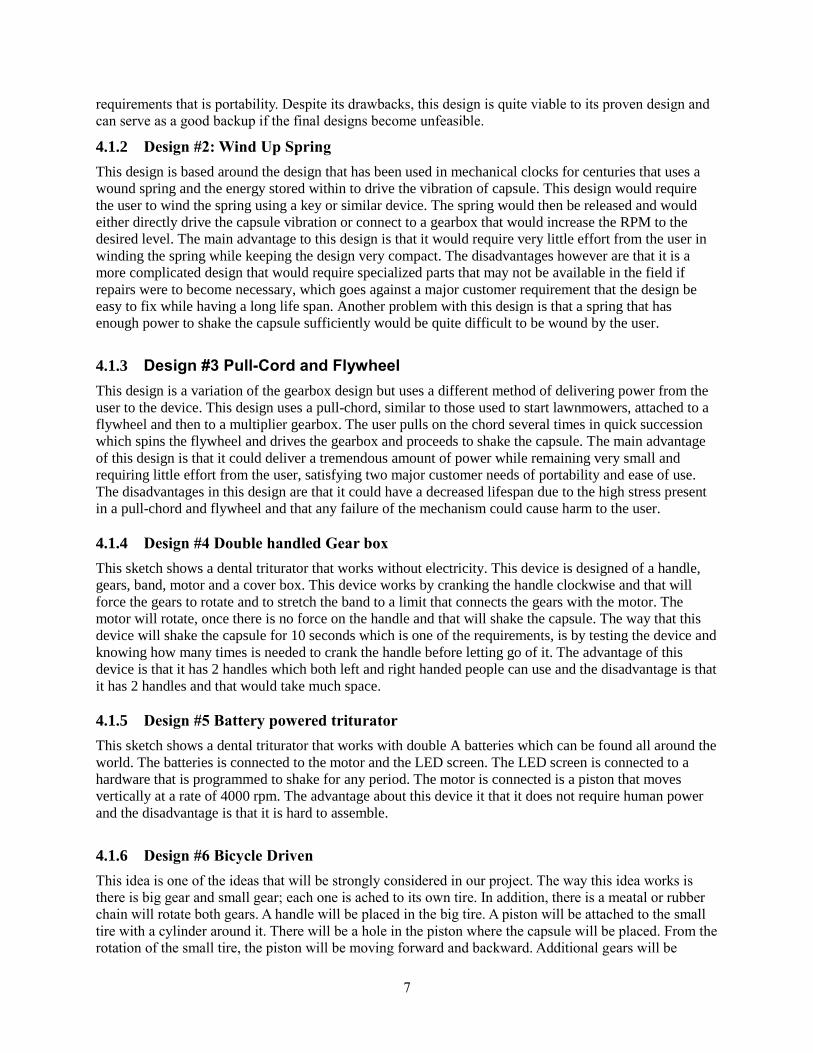
4.1.2 Design #2: Wind Up Spring
This design is based around the design that has been used in mechanical clocks for centuries that uses a
wound spring and the energy stored within to drive the vibration of capsule. This design would require
the user to wind the spring using a key or similar device. The spring would then be released and would
either directly drive the capsule vibration or connect to a gearbox that would increase the RPM to the
desired level. The main advantage to this design is that it would require very little effort from the user in
winding the spring while keeping the design very compact. The disadvantages however are that it is a
more complicated design that would require specialized parts that may not be available in the field if
repairs were to become necessary, which goes against a major customer requirement that the design be
easy to fix while having a long life span. Another problem with this design is that a spring that has
enough power to shake the capsule sufficiently would be quite difficult to be wound by the user.
4.1.3 Design #3 Pull-Cord and Flywheel
This design is a variation of the gearbox design but uses a different method of delivering power from the
user to the device. This design uses a pull-chord, similar to those used to start lawnmowers, attached to a
flywheel and then to a multiplier gearbox. The user pulls on the chord several times in quick succession
which spins the flywheel and drives the gearbox and proceeds to shake the capsule. The main advantage
of this design is that it could deliver a tremendous amount of power while remaining very small and
requiring little effort from the user, satisfying two major customer needs of portability and ease of use.
The disadvantages in this design are that it could have a decreased lifespan due to the high stress present
in a pull-chord and flywheel and that any failure of the mechanism could cause harm to the user.
4.1.4 Design #4 Double handled Gear box
This sketch shows a dental triturator that works without electricity. This device is designed of a handle,
gears, band, motor and a cover box. This device works by cranking the handle clockwise and that will
force the gears to rotate and to stretch the band to a limit that connects the gears with the motor. The
motor will rotate, once there is no force on the handle and that will shake the capsule. The way that this
device will shake the capsule for 10 seconds which is one of the requirements, is by testing the device and
knowing how many times is needed to crank the handle before letting go of it. The advantage of this
device is that it has 2 handles which both left and right handed people can use and the disadvantage is that
it has 2 handles and that would take much space.
4.1.5 Design #5 Battery powered triturator
This sketch shows a dental triturator that works with double A batteries which can be found all around the
world. The batteries is connected to the motor and the LED screen. The LED screen is connected to a
hardware that is programmed to shake for any period. The motor is connected is a piston that moves
vertically at a rate of 4000 rpm. The advantage about this device it that it does not require human power
and the disadvantage is that it is hard to assemble.
4.1.6 Design #6 Bicycle Driven
This idea is one of the ideas that will be strongly considered in our project. The way this idea works is
there is big gear and small gear; each one is ached to its own tire. In addition, there is a meatal or rubber
chain will rotate both gears. A handle will be placed in the big tire. A piston will be attached to the small
tire with a cylinder around it. There will be a hole in the piston where the capsule will be placed. From the
rotation of the small tire, the piston will be moving forward and backward. Additional gears will be

8
applied to the system to help in achieving (4000 rpm). The gear will look similar to the gear that can be
found in a bicycle. This design have positive features more than its negative. to be more specific, the
light weight and the less part the design have makes it perfect for a flexible movement since the team
will be using it in different countries . Some of the negative of this project that it may require a person
with athletic body to let t work.
4.1.7 Design # 7 Solar Power System
This design is that is more modern and it uses a nowadays technology. This design will uses solar panel to
collect sun light and turn it into electricity. this electricity will be stored in a battery and then will be sent
to the electric motor which will be really small and not more than ( 12 V ) . The motor will be attached to
gears to increase the speed to achieve (4000 rpm). A Small piston will be attached to the small gear to
shake the capsule. The design positive feature that it can be places in small package and it is easy to move
around also it do not require any effort to let it work. The negative effect that it can be expensive build
and fix.
4.1.8 Design #8 Rumble Motors
In this design we will use a rumble motor in order to vibrate the capsule. We will use a small batteries in
order to generate the rumble motor. The electric power will be taken from the batteries moving to the
rumble motor to transfer it to a mechanical energy. We have two issues using the batteries to generate the
rumble motor. The first issue is the short life expectancy of the batteries. The users must replace the
batteries daily depending on how many times they will use the device. The second issue is that we need to
use more than 4 batteries in order to get the power needed which is 4000 rpm and this might increase the
size of the device.
4.1.9 Design #9 Rechargeable Batteries
This design contain an electric motor and a rechargeable battery to source the electric motor. It has a
manual hand crank that we need to rotate it for a certain time in order to recharge the battery. There will
be a motor inside the device which is responsible of the rotational part. The rechargeable battery is used to
store electricity that can be used for a multiple times before having to be recharged. This idea is one of the
selected designs because it meet most of the costumer and engineering requirement which will be
discussed in section 5.1.
4.1.10 Design#10 pressurized air tube
In this device, will use pipe, gas cylinder, rubber. The idea is to Shake the capsule by using Air. The pipe
will be covered by two pieces of rubber in each side. The pipe will have a hole in the bottom of it and an
air will be following through it. So, the capsule will be moving forward and backward until it reaches
4000 rpm. The advantage of this device is that no electrical power need it for the device. On other hand
the disadvantage of this device that is gas cylinder heavy and expensive.
5 DESIGN SELECTED
This section of the report will describe in detail the final designs chosen by the team for further analysis
and refinement. The designs chosen to be take further are the Pull-Chord and Flywheel design as well as
the electric motor designs. These designs were chosen based on a number of factors, being their
adherence to the customer requirements as well as their versatility and adaptability. The reason versatility
is seen as important in this case is that each design can be seen as a chassis with a number of different
variations that would then be added to it after further analysis and prototyping determines which is the

9
most effective in accomplishing the goal. Selected design were chosen due to our Pugh chart that is
attached in appendix D.
5.1 Pull-Chord and Flywheel
The pull-chord design was inspired by the systems used to start lawnmowers and other tools that do not
use a starting motor to get the device started. The pull-chord is pulled a number of times by the user and
the attached flywheel keeps the power being given to the drive train consistent while the chord is retracted
into the module in between pulls. The drive train will, most likely, be attached to a multiplier gearbox to
achieve the necessary RPM if it is not already reached at the drive train.
This design meets many of the customer requirements that were given to us. This design would be easy to
use, smaller than most of the others, cheap, reliable, durable, and safe. The only thing required by the user
is to load the capsule and then pull on the chord a certain number of times. This amount would be
determined through prototyping so that the exact number of pulls necessary to shake the capsule for ten
seconds would be known, thereby taking the issue of timing out of the equation. This design would also
be cheaper to use than most others because most of the components would be modular and could be
purchased instead of Having to be manufactured by the team and, eventually, the dental students. This
modularity is what gave this design one of the highest scores among the rest of the designs in terms of
maintenance due to the abundance of replacement parts, especially if a gearbox does not become
necessary. The main disadvantages present in this design are the high stress forces involved. The pull-
chord produces a lot of torque that is delivered directly to the gearbox and the drive train. This level of
stress could lead to a much shorter lifespan in the individual parts unless heavier and more expensive
parts are used, which would get us closer to our limit of ten pounds and our project budget just so that the
device is usable rather than trying to make it more efficient. However, this expected lower lifespan is
offset by the aforementioned modularity. For example, the entire pull-chord and flywheel assembly can
be purchased online and replaced in just a few minutes in case of failure. In the case that a gearbox is used
and the pull-chord breaks, a hand crank could be attached to the same gearbox and cranked manually as a
last resort.
The pull-chord design is a proven design that is guaranteed to deliver the power necessary to the device
while remaining cheap and easy to use for the user without resorting to compromise. This usability,
combined with its reliability and versatility is what makes it one of our final two designs to be proposed.
5.1.1 Rechargeable Batteries
The recharge battery design is preferable as it meets most of the requirements. In this design when we
rotate the hand crank it will recharge the battery that is connected to the electric motor. There will be a
small gearing system for the hand crank in order to increases the speed of the output shaft and recharge
the battery. As it is shown in the sketch the hand crank can be used for both left right handed people. The
electric motor will take the power from the battery and shakes the capsule to mix the ingredients. As this
design is human powered it can be used anywhere around the world. it can be used anywhere as it doesn’t
require any external electricity. As the design contains simple parts the production cost will be around
$200 which is good for a final design cost. We completely enclosed the system in a box so that it can be
handled easily. Based on the required output speed the team will design gearing system for the hand crank
so that we will get the 4000 rpm required. All parts are easily replaceable as the damage of any individual
part needs only its replacement. The motor we will be using has a 29.5 mm long leads and it can reach a
speed of 23000 rpm which is more than the required rpm. The motor costs is between $3 to $6 and it
weights around 30 grams. The rechargeable batteries cost $20 and weights around 1.1 kg. In summary
this design has a fair price, light weight, human powered, easy to use, shake for specific time, can be used
anywhere, and has 2+ life expectancy [4],[5].

10
6 REFERENCES
[1]"GC EUROPE", Gceurope.com, 2017. [Online]. Available:
http://www.gceurope.com/products/detail.php?id=146.
[2]"ProMix 2 | DENTSPLY Middle East & Africa", Dentsplymea.com, 2017. [Online]. Available:
http://www.dentsplymea.com/products/restorative/restorative-equipment/promix-2.
[3]"Henry Schein Corporate Brand", Henryscheinbrand.com, 2017. [Online]. Available:
http://www.henryscheinbrand.com/product.php?leader=9001171.
[4] "Tenergy Nimh Battery For RC Cars, Robots, Security Systems". Batteryjunction.com. N.p., 2017.
Web. 25 Mar. 2017.
[5] Leads, Toy et al. "Toy DC Motor With Leads - ROB-09608 - Sparkfun Electronics". Sparkfun.com.
N.p., 2017. Web. 25 Mar. 2017.

11
7 APPENDICES
7.1 Appendix A (Client Approvel)

12
7.2 Appendix B (HoQ)

13
7.3 Appendix C: Design Sketches
7.3.1 Gear Box
7.3.2 Wind up Spring
7.3.3 Pull-Chord and Flywheel

14
7.3.4 Double Handled Gearbox
7.3.5 Battery Powered Triturator
7.3.6 Bicycle Driven

15
7.3.7 Solar Power System
7.3.8 Rumble Motors

16
7.3.9 Rechargeable batteries
7.3.10 Pressurized Air Tube

17
7.4 APPINDIX D (Pugh Chart)