Embed Size (px)
Citation preview

M-1
Hub City IndustriaLine™ Bearing Units
M
IndustriaLine
™ Bearing
s
Certified prints are available upon requestDOWNLOAD AVAILABLE CAD MODELS AT: WWW.HUBCITYINC.COM
EMAIL: [email protected] • www.hubcityinc.com
Mounted Bearing Features Index .............................................. M-1
Features Index ........................................................................... M-4
Engineering and Selection — Ball Bearing Units ....................... M-6
NEW - HVAC Air Handling Bearings .......................................... M-8
100 Series Pillow Blocks ............................................................ M-10
100 Series Flange Blocks ........................................................... M-11
100 & 200 Series Load Ratings .................................................. M-14
200 Series Pillow Blocks ............................................................ M-15
200 Series Flange Blocks ........................................................... M-23
200 Series Flange Brackets & Flange Cartridges ...................... M-27
200 Series Take Up Units ........................................................... M-28
Take-Up Frames — Ball Bearing Units ....................................... M-32
Ball Bearing Inserts .................................................................... M-35
350 Series Load Ratings ............................................................ M-37
350 Series Bearings ................................................................... M-38
Interchange Comparisons — Ball Bearing Units ........................ M-42
For Stainless Steel & Thermoplastic Composite Bearings, See Section O
Over 200 NEW items in this section!

CALL: (605) 225-0360 • FAX: (605) 225-0567M-2
Hub City IndustriaLine™ Bearing Units
Certified prints are available upon requestDOWNLOAD AVAILABLE CAD MODELS AT: WWW.HUBCITYINC.COM
Hub City offers a wide range of products in the IndustriaLine™ mounted ball bearing product line. These include pillow blocks, 2, 3 and 4 hole flange blocks, 4 hole piloted flange cartridges, and wide slot and narrow slot take-up units. Ball bearing units are available with
setscrew locking or eccentric locking collar, with narrow inner race or wide inner race, with normal duty or medium duty bearings. Housings are available in gray cast iron or Hub-Alloy®. Refer to Features Index for description of specific units.
Molded glass fiber reinforced polyamide retainer
Grade 10 Balls
Races and balls are 52100 steel. Races are hardened, ground and honed for quiet operation.
Slotted bolt holes
Rugged Cast Iron or Hub-Alloy® housing
Zone hardened Inner Race
Steel flingers are standard on wide inner race bearings only.
Typical Cross Section
Prelubricated with high quality lithium grease. 1/4-28 Zerk fitting provided to allow for relube.
Choice of narrow or wide inner race, setscrew locking or eccentric collar locking, normal duty or medium duty bearings.
Knurled cup point setscrews at 120° to minimize inner ring distortion.
Recessed housing base to accommodate uneven mounting surfaces.
Spherical outer race to allow up to 1.5° misalignment.
All bearings have single lip Nitrile rubber seals with steel trash guard.
(Continued on next page)

M-3
Hub City IndustriaLine™ Bearing Units
M
IndustriaLine
™ Bearing
s
Certified prints are available upon requestDOWNLOAD AVAILABLE CAD MODELS AT: WWW.HUBCITYINC.COM
EMAIL: [email protected] • www.hubcityinc.com
Housing
Housings for Hub City bearing units are precision machined from rugged cast iron or high strength Hub-Alloy® castings.
Hub-Alloy® is a cast ferrous material this is manufactured in a carefully controlled process to produce properties exceeding the specifications listed below. Hub-Alloy® can be used to replace malleable iron or ductile iron. It is recommended for severe applications where the stronger material is required to withstand heavy loads imposed on the housing. Hub-Alloy® has tensile strength properties in the range 50-65,000 psi, yield strength in the range 32-45,000 psi, and elongation in the range 10-12%. Specific properties of particular housings vary according to the configuration of the housing.
Cast iron housings meet or exceed the requirements of SAE G3000 gray iron. Typical tensile strength is 30,000 psi.
Hub City can furnish modified or special units to suit customer requirements. Typical modifications include:
• Housing modifications
• Special grease types
• Dust caps
• Auxiliary anti-rotation devices
• Custom bearing units with special housings and/or bearings
Modified or special units may be subject to increased lead time and minimum production order quantities.
Bearings have spherical outer races to accommodate up to 1.5° misalignment. Races and balls are made of SAE 52100 vacuum degassed bearing quality steel. Ball retainers are made of molded, glass fiber reinforced polyamide. Races are hardened, ground and honed for quiet operation, and Grade 10 balls are used. Inner races are zone hardened in the ball raceway and seal contact areas. The setscrew end is unhardened to prevent cracking at the setscrew threads. Setscrews are located at 120° to minimize inner ring distortion, and have knurled cup point to resist loosening under vibration. Seals have a nitrile rubber lip bonded to a steel trash
guard.. The positive contact, low friction seal rides on the precision ground surface of the inner race. Wide inner race bearings also have steel flingers that rotate with the inner race to provide extra protection. All ball bearings are prelubricated with high quality lithium grease. Hub City bearings have an operating temperature range of -25° F to 225° F.
Bearings
Special Modications
Features

CALL: (605) 225-0360 • FAX: (605) 225-0567M-4
Hub City IndustriaLine™ Bearing Units
Certified prints are available upon requestDOWNLOAD AVAILABLE CAD MODELS AT: WWW.HUBCITYINC.COM
RATING OUTLINE SHAFT BEARING BACKING HOUSING SIZE INTERCHANGE
SERIES TABLES DIMENSIONS LOCKING LUBRICATION HEIGHT MATERIAL RANGE REFERENCE
PB120 Page Page Eccentric Relube High HUB-ALLOY® 1/2 - 1-7/16 Page
M-14 M-10 Collar M-42
PB150 Page Page Setscrew Relube High HUB-ALLOY® 1/2 - 1-7/16 Page
M-14 M-10 M-42
PB220 Page Page Eccentric Relube Low Cast Iron 1/2 - 2-7/16 Page
M-14 M-15 Collar M-43
PB221 Page Page Eccentric Relube High Cast Iron 1/2 - 2-7/16 Page
M-14 M-15 Collar M-43
PB220W Page Page Eccentric Relube Low Cast Iron 3/4 - 2-7/16 Page
M-14 M-16 Collar M-43
PB221W Page Page Eccentric Relube High Cast Iron 3/4 - 2-7/16 Page
M-14 M-16 Collar M-43
PB220HW Page Page Eccentric Relube Low HUB-ALLOY® 3/4 - 2-7/16 Page
M-14 M-17 Collar M-43
PB221HW Page Page Eccentric Relube High HUB-ALLOY® 3/4 - 2-7/16 Page
M-14 M-17 Collar M-43
PB250 Page Page Setscrew Relube Low Cast Iron 1/2 - 2-15/16 Page
M-14 M-18 M-43
PB251 Page Page Setscrew Relube High Cast Iron 1/2 - 2-15/16 Page
M-14 M-18 M-43
PB250W Page Page Setscrew Relube Low Cast Iron 5/8 - 2-7/16 Page
M-14 M-19 M-43
PB251W Page Page Setscrew Relube High Cast Iron 5/8 - 2-7/16 Page
M-14 M-19 M-43
PB250HW Page Page Setscrew Relube Low HUB-ALLOY® 5/8 - 2-7/16 Page
M-14 M-20 M-43
PB251HW Page Page Setscrew Relube High HUB-ALLOY® 5/8 - 2-7/16 Page
M-14 M-20 M-43
PB281WAH Page Page Concentric Relube High Cast Iron 3/4 - 2-7/16
M-14 M-8
TPB220 Page Page EccLock Relube Tapped Cast Iron 1/2 - 2-3/16 Page
M-14 M-21 Base M-42
TPB220W Page Page EccLock Relube Tapped Cast Iron 5/8 - 2-3/16 Page
M-14 M-21 Base M-42
TPB250 Page Page Setscrew Relube Tapped Cast Iron 1/2 - 2-3/16 Page
M-14 M-22 Base M-42
TPB250W Page Page Setscrew Relube Tapped Cast Iron 5/8 - 2-3/16 Page
M-14 M-22 Base M-42
PB350 Page Page Setscrew Relube High Cast Iron 1 - 3-1/2 Page
M-37 M-38 M-45
PB350H Page Page Setscrew Relube High HUB-ALLOY® 1 - 3-1/2 Page
M-37 M-39 M-45
Features Index
Ball Bearing Pillow Blocks

M-5
Hub City IndustriaLine™ Bearing Units
M
IndustriaLine
™ Bearing
s
Certified prints are available upon requestDOWNLOAD AVAILABLE CAD MODELS AT: WWW.HUBCITYINC.COM
EMAIL: [email protected] • www.hubcityinc.com
* WIDE SLOT UNITS AVAILABLE ON MADE-TO-ORDER BASIS.
Features Index
Ball Bearing Flange Blocks & Flange Cartridges
SHAFT RATING OUTLINE SHAFT BEARING FLANGE HOUSING SIZE INTERCHANGE SERIES TABLES DIMENSIONS LOCKING LUBRICATION STYLE MATERIAL RANGE REFERENCE FB110 Page Page Setscrew Non-Relube 2-Hole HUB-ALLOY® 1/2 - 1-7/16 Page M-14 M-11 M-42 FB120 Page Page Eccentric Relube 3-Hole HUB-ALLOY® 1/2 - 1-7/16 Page M-14 M-12 Collar M-42 FB130 Page Page Eccentric Relube 2-Hole HUB-ALLOY® 1/2 - 1-7/16 Page M-14 M-12 Collar M-42 FB150 Page Page Setscrew Relube 3-Hole HUB-ALLOY® 1/2 - 1-7/16 Page M-14 M-13 M-42 FB 160 Page Page Setscrew Relube 2-Hole HUB-ALLOY® 1/2 - 1-7/16 Page M-14 M-13 M-42 FB220 Page Page Eccentric Relube 4-Hole Cast Iron 1/2 - 2-7/16 Page M-14 M-23 Collar M-44 FB220HW Page Page Eccentric Relube 4-Hole HUB-ALLOY® 3/4 - 2-7/16 Page M-14 M-24 Collar M-44 FB230 Page Page Eccentric Relube 2-Hole Cast Iron 1/2 - 2-3/16 Page M-14 M-23 Collar M-44 FB230HW Page Page Eccentric Relube 2-Hole HUB-ALLOY® 3/4 - 2-7/16 Page M-14 M-24 Collar M-44 FB250 Page Page Setscrew Relube 4-Hole Cast Iron 1/2 - 2-15/16 Page M-14 M-25 M-44 FB250HW Page Page Setscrew Relube 4-Hole HUB-ALLOY® 5/8 - 2-7/16 Page M-14 M-26 M-44 FB260 Page Page Setscrew Relube 2-Hole Cast Iron 1/2 - 2-3/16 Page M-14 M-25 M-44 FB260HW Page Page Setscrew Relube 2-Hole HUB-ALLOY® 5/8 - 2-7/16 Page M-14 M-26 M-44 FB280HWAH Page Page Concentric Relube 4-Hole HUB-ALLOY® 3/4 - 2-7/16 – M-14 M-8 FB290HWAH Page Page Concentric Relube 2-Hole HUB-ALLOY® 3/4 - 2-7/16 – M-14 M-9 FC250 Page Page Setscrew Relube 4-Hole Cast Iron 1/2 - 2-7/16 – M-14 M-27 Piloted FR250W Page Page Setscrew Relube 3-Hole 3/4 - 2s – M-14 M-27 Bracket Cast Iron FB350 Page Page Setscrew Relube 4-Hole Cast Iron 1 - 3-1/2 Page M-37 M-38 M-46 FB350H Page Page Setscrew Relube 4-Hole HUB-ALLOY® 1 - 3-1/2 Page M-37 M-39 M-46 FC350 Page Page Setscrew Relube 4-Hole Cast Iron 1-1/4 - 3-1/2 Page M-37 M-40 Piloted M-46
SHAFT RATING OUTLINE SHAFT BEARING SLOT HOUSING SIZE INTERCHANGE
SERIES TABLES DIMENSIONS LOCKING LUBRICATION WIDTH MATERIAL RANGE REFERENCE TU220 Page Page Eccentric Relube Standard Cast Iron 1/2 - 2-7/16 Page M-14 M-28 Collar M-45 TU220W Page Page Eccentric Relube Standard Cast Iron 3/4 - 2-7/16 Page M-14 M-29 Collar M-45 TU250 Page Page Setscrew Relube Standard Cast Iron 1/2 - 2-7/16 Page M-14 M-28 M-45 TU250W Page Page Setscrew Relube Standard Cast Iron 5/8 - 2-7/16 Page M-14 M-29 M-45 WSTU220 Page Page Eccentric Relube Wide Slot Cast Iron 3/4 - 2-7/16 Page M-14 M-30 Collar M-45 WSTU250 Page Page Setscrew Relube Wide Slot Cast Iron 3/4 - 2-7/16 Page M-14 M-30 M-45 WSTU220W Page Page Eccentric Relube Wide Slot Cast Iron 1-7/16 - 3 Page M-14 M-31 Collar M-45 WSTU250W Page Page Setscrew Relube Wide Slot Cast Iron 1-7/16 - 3 Page M-14 M-31 M-45 TU350 Page Page Setscrew Relube Standard Cast Iron 1-7/16 - 3 – M-37 M-40 WSTU350 Page Page Setscrew Relube Wide Slot Cast Iron 1-7/16 - 3 – M-37 M-41
Ball Bearing Take-Up Units

CALL: (605) 225-0360 • FAX: (605) 225-0567M-6
Hub City IndustriaLine™ Bearing Units
Certified prints are available upon requestDOWNLOAD AVAILABLE CAD MODELS AT: WWW.HUBCITYINC.COM
Maximum SpeedMaximum speed limits listed for the ball bearing products described in this catalog should be used as a guide and considered along with other factors affecting bearing operation. Load characteristics, bearing lubrication, and temperature factors all influence bearing operation. It is possible that cataloged speed limits may be exceeded after a complete application analysis is completed by factory engineers.
Bearing LifeBearing life is commonly referred to in terms of the number of hours of operation at a given speed, that 90% of the bearings in a lot can equal or exceed before the onset of fatigue failure. This is called the L-10 life of a bearing.
The ball bearing unit load ratings published in this catalog are based upon AFBMA Standard Section 9, Load Ratings and Fatigue Life Ratings for Ball Bearings and are the steady radial loads at which the bearings will endure at various speeds for 500 hours L-10 life, or 2,500 hours average life (average life is considered to be 5 times L-10 life).
Bearing LoadsRadial loads and thrust force in combination are the principal load components of bearing applied loads. Hub City ball bearing unit ratings are based upon the radial load capacity of the bearing. For applications where bearings are required to absorb thrust forces in addition to normal radial loads, the following considerations must be made concerning the magnitude of the thrust force.
1. When thrust loads are less than 1/2 of the radial load – the equivalent load should be considered the same as the radial load and the selection made based upon the applied radial load.
2. When thrust loads are equal to or greater than 1/2 of the radial load – the equivalent load is determined by adding the radial and thrust loads together. The bearing selection is based upon using this total load as the equivalent applied radial load.
If thrust loads are equal to or exceed the radial loads, consult the factory.
Bearing SelectionSelection of the proper Hub City bearing unit for a determined speed and load can be made by referring to the load rating tables. Proper selection is made by finding a bearing having the desired bore size which has a load rating equal to or greater than the radial or equivalent radial load required for the application.
Engineering DataBearing reaction loads are caused by forces acting on the shaft supported by the bearings. These forces are a result of the weight of the shafting and components mounted on the shafting, bending loads due to belt or chain pull, gear reaction loads, and off center or unbalanced loads. These loads must be combined into a single resultant load of known magnitude and direction for each bearing.
Whether the load is applied between bearings on a shaft supported by two bearings or outboard of one of the bearings is important to proper bearing selection. The magnitude and direction of the load for either case may be calculated by taking moments about the other bearing.
Selection Example 1:Radial Load Service Life Expectancy Selection
Select a mounted bearing pillow block unit to meet the following application requirements:a. Shaft diameter of 1 inch b. Shaft speed is 1500 RPM.c. Radial load requirement is 850 Lbs. d. Life requirement is 1000 hours L-10 (5000 hours average life)
Step 1.From the rating tables on pages M-14 and M-37, locate the one inch shaft diameter line and follow that line to the right to the 1500 RPM column. Note that the radial load capacity for 100 Series bearings and 200 Series bearings (ratings, page M-14) is 890 pounds. The radial load capacity for 350 Series bearings (ratings, page M-37) is 1230 pounds.
BA
L
BEARING NO. 1 BEARING NO. 2Load on Bearing No. 1 = L x B Load on Bearing No. 2 = L x A A + B A + B
L
C D
BEARING NO. 3 BEARING NO. 4Load on Bearing No. 3 = L x D Load on Bearing No. 4 = L x (C + D) ����� C C
WHEN COMBINATION FORCES OR UNBALANCED LOADS ARE PRESENT, BEARING REACTION LOAD CALCULATIONS SHOULD BE REVIEWED WITH FACTORY ENGINEERING.
L = APPLIED EQUIVALENT LOAD
Engineering and Selection Information

M-7
Hub City IndustriaLine™ Bearing Units
M
IndustriaLine
™ Bearing
s
Certified prints are available upon requestDOWNLOAD AVAILABLE CAD MODELS AT: WWW.HUBCITYINC.COM
EMAIL: [email protected] • www.hubcityinc.com
Selection Example 1:Radial Load Service Life Expectancy Selection (cont.)
Step 2.The published radial load capacities are based on an L-10 life of 500 hours and must be modified to suit the application requirement of 1000 hours L-10 life by using the proper multiplier from the chart below each rating table. Calculate the equivalent radial load capacity for 1000 hours L-10 life expectancy as follows:
For 100 or 200 Series Units 890 Lbs. radial capacityx .794 1000 hours L-10 life factor 707 Lbs. radial capacity for 1000 hours L-10 life
For 350 Series: Units1230 Lbs. radical capacityx .794 1000 hours L-10 life factor 977 Lbs. radical capacity for 1000 hours L-10 life
Step 3.The application radial load requirement of 850 pounds is greater than the radial load capacity for 1000 hours L-10 life for the 100 or 200 Series bearing units. The radial load capacity of the 350 Series bearing unit is 977 pounds and is greater than the application requirement of 650 pounds. A 350 Series bearing unit is the proper selection.
Since a mounted bearing pillow block is required, a 350 Series pillow block with 1 inch bore should be specified.
Selection Example 2:Combination Radial and Thrust Load Requirement
Select a Hub City mounted bearing flange block to meet the following conditions:
a. Shaft diameter is 1-3/16. b. A combination load is applied consisting of: Radial load 400 pounds Thrust load is 250 poundsc. Shaft speed is 500 RPMd. The L-10 life requirement is 500 hours (2500 hours average
life) Step 1.From the load rating tables, M-14 and M-37, locate the 1-3/16 inch shaft size line and follow this line to the right to the 500 RPM column. The radial load capacity for 100 Series (page M-14) and 200 Series (page M-14) bearing units is 1780 pounds.
The radial load capacity for 350 Series (page M-37) bearing units is 2330 pounds.
Step 2.Since the application L-10 life requirement of 500 hours is what the catalog rating charts are based on there’s no need to apply further modifying factors.
Step 3.Because the applied thrust load of 250 pounds is more than half of the applied radial load of 400 pounds, these loads must be added together to obtain the equivalent radial load requirement.
Equivalent Radial Load = 400 Lbs. + 250 Lbs. = 650 Lbs.
Step 4.The equivalent radial load requirement of 650 pounds is less than the catalog radial load capacity for 100 Series, 200 Series, or 350 Series bearing units.
The application requirement is for a flange block unit. A choice must be made as to whether a 2-bolt, 3-bolt, or 4-bolt flange is desired.
The proper selection can then be made based on the prefer-ence for housing material (gray iron, or HUB-ALLOY®) and type of shaft locking preference (setscrew or eccentric collar locking) and whether a non-relube or relube type bearing is required.
Engineering and Selection Information
For Lubrication and Mounting Instructions, Refer to section S

CALL: (605) 225-0360 • FAX: (605) 225-0567M-8
Hub City IndustriaLine™ Bearing Units
Certified prints are available upon requestDOWNLOAD AVAILABLE CAD MODELS AT: WWW.HUBCITYINC.COM
•Squeeze lock collar for concentric 360 degree locking•HVAC quality bearing insert with grade 10 balls•Superfinished raceways•Anti-rotation pins•Air handling fit in housing•Precision bored cast iron housing•Wide inner race•Nitrile rubber seals with steel flingers•Prelubricated at factory with premium grease•Noise tested
HVAC Cast Iron Pillow Blocks
Series PB281WAH HVAC Bearing Units - for High Shaft Heights
•Squeeze lock collar for concentric 360 degree locking•HVAC quality bearing insert with grade 10 balls•Superfinished raceways•Anti-rotation pins•Air handling fit in housing•Precision bored HuballoyTM housing•Higher strength and greater impact resistance •Nitrile rubber seals with steel flingers•Prelubricated at factory with premium grease•Wide inner race•Noise tested
HVAC HubAlloy™ Four-Hole Flange Blocks
Series FB280HWAH HVAC Bearing Units
Part Numbers are specified by “PB281WAH” and Bore Size. Example: PB281WAH x 3/4.For Load Ratings, see page M-14.T-Zerk: 1/4-28 Taper
For replacement inserts use B280WAH bearing inserts. See page M-9.
For replacement inserts use B280WAH bearing inserts. See page M-9.
DIMENSIONS SHAFT E WT. SIZE A B C D MIN. MAX F G H J L M S LBS.
3/4 1.938 2.563 1.756 2.250 3.250 4.125 5.125 1.375 0.563 0.375 1.563 0.870 1.370 2.0 1 1.438 2.750 1.937 2.500 3.500 4.500 5.500 1.500 0.625 0.375 1.719 0.950 1.510 2.5 1-3/16, 1-1/4S 1.688 3.250 2.185 3.000 4.250 5.125 6.375 1.750 0.750 0.500 1.875 1.030 1.650 3.1 1-1/4, 1-7/16 1.875 2.688 2.575 3.438 4.688 5.500 6.750 1.875 0.688 0.500 2.125 1.180 1.870 4.2 1-1/2 2, 2.188* 4.000 2.693 3.875 5.125 5.938 7.125 1.875 0.813 0.500 2.438 1.360 2.110 4.9 1-11/16, 1-3/4 2.188 4.250 2.933 4.125 5.375 6.125 7.375 2.000 0.813 0.500 2.438 1.370 2.120 5.5 1-15/16 2.250 4.500 3.386 4.313 5.813 6.750 8.375 2.000 0.813 0.625 2.656 1.520 2.270 6.5 2, 2-3/16 2.500 5.000 3.504 4.750 6.438 7.375 9.000 2.250 0.938 0.625 2.781 1.560 2.430 8.8 2-7/16 2.750 5.563 4.055 5.250 6.750 8.125 9.625 2.500 1.188 0.625 3.281 1.850 2.850 11.5
Part Numbers are specified by “FB280HWAH” and Bore Size. Example: FB280HWAH x 3/4.For Load Ratings, see page M-14.T-Zerk: 1/4-28 Taper
DIMENSIONS SHAFT WT. SIZE B B.C. C D E H J L M S LBS.
3/4 3.313 3.531 1.756 2.313 2.500 0.438 0.375 1.625 1.125 1.370 0.9 1 3.688 3.891 1.937 2.625 2.750 0.563 0.438 1.719 1.188 1.510 1.5 1-3/16, 1-1/4S 4.188 4.594 2.185 3.000 3.250 0.625 0.438 1.688 1.188 1.650 2.2 1-1/4, 1-7/16 4.688 5.125 2.575 3.500 3.625 0.656 0.500 2.000 1.250 1.870 2.8 1-1/2 5.063 5.656 2.693 3.875 4.000 0.688 0.500 2.313 1.438 2.110 3.7 1-11/16, 1-3/4 5.250 5.828 2.933 4.125 4.125 0.688 0.500 2.313 1.438 2.120 4.1 1-15/16 5.500 6.188 3.386 4.375 1.375 0.719 0.500 2.625 1.594 2.270 4.6 2, 2-3/16 6.375 7.250 3.504 4.750 5.125 0.719 0.625 2.781 1.781 2.430 6.2 2-7/16 6.875 7.938 4.055 5.313 5.625 0.813 0.625 3.188 1.938 2.850 8.5
C
E SQUARE
B SQUARE
B.C.
J BOLT SIZE
D
MSL
H
T ZERK
M
S
G
L
D
H
E MIN.E MAX.
F
A
CB
J BOLT SIZE
T ZERK
M-9
Hub City IndustriaLine™ Bearing Units
M
IndustriaLine
™ Bearing
s
Certified prints are available upon requestDOWNLOAD AVAILABLE CAD MODELS AT: WWW.HUBCITYINC.COM
EMAIL: [email protected] • www.hubcityinc.com
D
E
J BOLT SIZE
M
S
L
CB
H
T ZERK
Part Numbers are specified by “B280WAH” and Bore Size. Example: B280WAH x 3/4. Used in PB281WAH, FB280HWAH, and FB290HWAH units.
•Squeeze lock collar for concentric 360 degree locking•HVAC quality bearing insert with grade 10 balls•Superfinished raceways•Anti-rotation pins•Air handling fit in housing•Precision bored HuballoyTM housing•Higher strength and greater impact resistance •Nitrile rubber seals with steel flingers•Prelubricated at factory with premium grease•Wide inner race•Noise tested
HVAC HubAlloy™ Two-Hole Flange Blocks
Series FB290HWAH HVAC Bearing Units
DIMENSIONS SHAFT WT. SIZE B C D E H J L M S LBS.
3/4 4.344 1.756 2.313 3.531 0.438 0.375 1.625 1.125 1.370 0.8 1 4.828 1.937 2.625 3.891 0.563 0.438 1.719 1.188 1.510 1.2 1-3/16, 1-1/4S 5.531 2.185 3.000 4.594 0.563 0.438 1.688 1.188 1.650 1.8 1-1/4, 1-7/16 6.188 2.575 3.500 5.125 0.563 0.500 2.000 1.250 1.870 2.4 1-1/2 6.719 2.693 3.875 5.656 0.563 0.500 2.313 1.438 2.110 3.1 1-11/16, 1-3/4 6.953 2.933 4.125 5.828 0.563 0.500 2.313 1.438 2.120 3.6 1-15/16 7.313 3.386 4.375 6.188 0.625 0.500 2.625 1.594 2.270 4.0 2, 2-3/16 8.500 3.504 4.750 7.250 0.781 0.625 2.781 1.781 2.430 5.2 2-7/16 9.688 4.055 5.313 7.938 0.813 0.750 3.188 1.938 2.850 7.7
HVAC Bearing Inserts
Series B280WAH
DIMENSIONS SHAFT SOCKET WT. SIZE C D M S W CAPSCREW LBS.
3/4 1.756 1.8504 0.870 1.370 0.591 8-32x5/8 UNF 0.3 1 1.937 2.0472 0.947 1.510 0.591 8-32x5/8 UNF 0.5 1-3/16, 1-1/4S 2.185 2.4409 1.204 1.650 0.709 8-32x5/8 UNF 0.7 1-1/4, 1-7/16 2.575 2.8346 1.181 1.870 0.748 10-24x3/4 UNC 1.0 1-1/2 2.693 3.1496 1.620 2.110 0.866 10-24x3/4 UNC 1.3 1-11/16, 1-3/4 2.933 3.3465 1.372 2.120 0.866 10-24x3/4 UNC 1.6 1-15/16 3.386 3.5433 1.522 2.270 0.866 1/4-20x1 UNC 1.6 2 , 2-3/16 3.504 3.9370 1.556 2.430 0.984 1/4-20x1 UNC 2.5 2-7/16 4.055 4.3307 1.850 2.850 1.063 5/16-18x1 UNC 3.8
M
W
S
(1) SOCKETCAPSCREW
DC
Part Numbers are specified by “FB290HWAH” and Bore Size. Example: FB290HWAH x 3/4.For Load Ratings, see page M-14.
For replacement inserts use B280WAH bearing inserts. See below.T-Zerk: 1/4-28 Taper
CALL: (605) 225-0360 • FAX: (605) 225-0567M-10
Hub City IndustriaLine™ Bearing Units
Certified prints are available upon requestDOWNLOAD AVAILABLE CAD MODELS AT: WWW.HUBCITYINC.COM
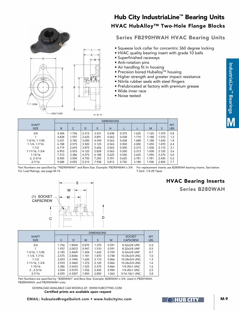
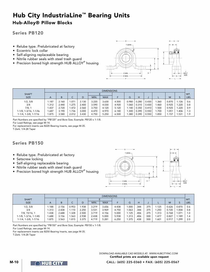
• Relube type. Prelubricated at factory• Setscrew locking• Self-aligning replaceable bearing• Nitrile rubber seals with steel trash guard• Precision bored high strength HUB ALLOY® housing
Part Numbers are specified by “PB150” and Bore Size; Example: PB150 x 1-1/8.For Load Ratings, see page M-14.For replacement inserts use B250 Bearing Inserts, see page M-35.T-Zerk: 1/4-28 Taper
D
B
H
A
FE MAX.E MIN.
T ZERK M
S
C
LG
JBOLTSIZE
Part Numbers are specified by “PB120” and Bore Size; Example: PB120 x 1-1/8.For Load Ratings, see page M-14.For replacement inserts use B220 Bearing Inserts, see page M-35.T-Zerk: 1/4-28 Taper
DIMENSIONS SHAFT E WT. SIZE A B C D MIN. MAX F G H J L M S LBS.
1/2, 5/8 1.188 2.156 0.953 1.938 3.219 3.656 4.438 1.000 .344 .375 1.125 0.626 0.870 0.6 3/4 1.313 2.438 1.110 2.250 3.531 3.969 4.750 1.063 .344 .375 1.250 0.720 1.004 0.8 7/8, 15/16, 1 1.438 2.688 1.328 2.500 3.719 4.156 5.000 1.125 .406 .375 1.313 0.768 1.071 1.0 1-1/8, 1-3/16, 1-1/4S 1.688 3.156 1.563 2.938 2.438 5.000 5.938 1.313 .406 .500 1.477 0.827 1.189 1.4 1-1/4, 1-3/8, 1-7/16 1.875 3.563 1.815 3.375 4.719 5.281 6.250 1.375 .438 .500 1.601 0.917 1.299 2.0
DIMENSIONS SHAFT E WT. SIZE A B C D MIN. MAX F G H J L M S LBS.
1/2, 5/8 1.187 2.160 1.071 2.130 3.220 3.630 4.500 0.980 0.280 0.430 1.360 0.870 1.126 0.6 3/4 1.312 2.440 1.275 2.400 3.590 4.030 4.920 1.060 0.310 0.430 1.460 0.925 1.220 0.8 7/8, 1 1.437 2.720 1.472 2.560 3.750 4.120 5.120 1.140 0.350 0.410 1.500 0.925 1.220 0.9 1-1/8, 1-3/16, 1-1/4s 1.687 3.190 1.736 3.000 4.470 4.970 6.140 1.300 0.390 0.550 1.700 1.051 1.406 1.3 1-1/4, 1-3/8, 1-7/16 1.875 3.580 2.012 3.430 4.750 5.250 6.500 1.380 0.390 0.550 1.850 1.157 1.531 1.9
Hub-Alloy® Pillow Blocks
Series PB150
• Relube type. Prelubricated at factory• Eccentric lock collar• Self-aligning replaceable bearing• Nitrile rubber seals with steel trash guard• Precision bored high strength HUB ALLOY® housing
Series PB120
C
H
FE MAX.E MIN.
A
B
T ZERK
D
LG
JBOLTSIZE
M
S

M-11
Hub City IndustriaLine™ Bearing Units
M
IndustriaLine
™ Bearing
s
Certified prints are available upon requestDOWNLOAD AVAILABLE CAD MODELS AT: WWW.HUBCITYINC.COM
EMAIL: [email protected] • www.hubcityinc.com
Dimensions shown are for reference only.
Part Numbers are specified by “FB110” and Bore Size; Example: FB110 x 1/2.For Load Ratings, see page M-14. For Comparison Charts, see page M-36.For replacement inserts use B250 Bearing Inserts, see page M-35.T-Set Screw: 1/4-28
T SETSCREW
D
E B
H
L
S
C
MJ
• Non-relube type. Prelubricated at factory
• Setscrew locking
• Self-aligning replaceable bearing
• Nitrile rubber seals with steel trash guard
• Precision bored high strength HUB-ALLOY® housing
DIMENSIONS SHAFT WT. SIZE B C D E H J L M S LBS. 1/2, 5/8 3.190 0.953 2.200 2.500 0.380 0.280 1.020 0.710 0.870 0.6 3/4 3.540 1.110 2.400 2.815 0.430 0.340 1.160 0.790 1.004 0.8 7/8, 1 3.740 1.328 2.520 2.992 0.430 0.340 1.208 0.790 1.071 0.8 1-1/8, 1-3/16, 1-1/4s 4.450 1.563 2.990 3.560 0.470 0.410 1.340 0.890 1.189 1.1 1-1/4, 1-3/8, 1-7/16 4.800 1.815 3.500 3.937 0.510 0.410 1.471 0.940 1.299 1.5
FB110 Two-Hole Flange Block
Hub-Alloy® Flange Blocks

CALL: (605) 225-0360 • FAX: (605) 225-0567M-12
Hub City IndustriaLine™ Bearing Units
Certified prints are available upon requestDOWNLOAD AVAILABLE CAD MODELS AT: WWW.HUBCITYINC.COM
Dimensions shown are for reference only.
Hub-Alloy® Flange Blocks
Part Numbers are specified by “FB120” and Bore Size; Example: FB120 x 3/4.For Load Ratings, see page M-14. For Comparison Charts, see page M-42.For replacement inserts use B220 Bearing Inserts, see page M-35.T-Zerk: 1/4-28 Taper
Part Numbers are specified by “FB130” and Bore Size; Example: FB130 x 3/4.For Load Ratings, see page M-14. For Comparison Charts, see page M-42.For replacement inserts use B220 Bearing Inserts, see page M-35.T-Zerk: 1/4-28 Taper
• Relube type. Prelubricated at factory• Eccentric locking collar• Self-aligning replaceable bearing• Nitrile rubber seals with steel trash guard• Precision bored high strength HUB-ALLOY® housing
• Relube type. Prelubricated at factory• Eccentric locking collar• Self-aligning replaceable bearing• Nitrile x seals with steel trash guard• Precision bored high strength HUB-ALLOY® housing
DIMENSIONS SHAFT WT. SIZE B C D E H J L M S LBS. 1/2, 5/8 3.190 1.071 1.930 2.500 0.390 0.280 1.280 0.690 1.126 0.6 3/4 3.560 1.275 2.440 2.811 0.390 0.340 1.350 0.790 1.220 0.8 7/8, 1 3.750 1.472 2.830 3.000 0.470 0.340 1.330 0.790 1.220 0.8 1-1/8, 1-3/16, 1-1/4s 4.440 1.736 3.310 3.563 0.470 0.410 1.560 0.870 1.406 1.1 1-1/4, 1-3/8, 1-7/16 4.800 2.012 3.540 3.937 0.530 0.410 1.730 0.940 1.531 1.7
DIMENSIONS SHAFT WT. SIZE B C D E H J L M S LBS. 1/2, 5/8 3.190 1.071 2.200 2.500 0.380 0.280 1.260 0.710 1.126 0.6 3/4 3.540 1.275 2.400 2.815 0.430 0.340 1.380 0.790 1.220 0.8 7/8, 1 3.740 1.472 2.520 2.992 0.430 0.340 1.360 0.790 1.220 0.8 1-1/8, 1-3/16, 1-1/4s 4.450 1.736 2.990 3.560 0.470 0.410 1.560 0.890 1.406 1.1 1-1/4, 1-3/8, 1-7/16 4.800 2.012 3.500 3.937 0.510 0.410 1.710 0.940 1.531 1.5
Series FB120, FB130FB120 Three-Hole Flange Block
FB130 Two-Hole Flange Block
T ZERK
J
C
H
S
L
BE
D
M
T ZERK
D
E B
H
LS
C
MJ

M-13
Hub City IndustriaLine™ Bearing Units
M
IndustriaLine
™ Bearing
s
Certified prints are available upon requestDOWNLOAD AVAILABLE CAD MODELS AT: WWW.HUBCITYINC.COM
EMAIL: [email protected] • www.hubcityinc.com
Part Numbers are specified by “FB150” and Bore Size; Example: FB150 x 3/4.‡ Holes are cast, some variation may be expected.For Load Ratings, see page M-14. For Comparison Charts, see page M-42.
For replacement inserts use B250 Bearing Inserts, see page M-35.T-Zerk: 1/4-28 Taper
Part Numbers are specified by “FB160” and Bore Size; Example: FB160 x 3/4.‡ Holes are cast, some variation may be expected.For Load Ratings, see page M-14. For Comparison Charts, see page M-42.
For replacement inserts use B250 Bearing Inserts, see page M-35.T-Zerk: 1/4-28 Taper
T ZERK
J
C
H
S
L
BE
D
M
• Relube type. Prelubricated at factory• Setscrew locking• Self-aligning replaceable bearing• Nitrile rubber seals with steel trash guard• Precision bored high strength HUB-ALLOY® housing
• Relube type. Prelubricated at factory• Setscrew locking• Self-aligning replaceable bearing• Nitrile rubber seals with steel trash guard• Precision bored high strength HUB-ALLOY® housing
T ZERK
D
E B
H
L
S
C
MJ
DIMENSIONS SHAFT WT. SIZE B C D E H J‡ L M S LBS. 1/2, 5/8 3.190 0.953 1.930 2.500 0.390 0.280 1.040 0.690 0.870 0.6 3/4 3.560 1.110 2.440 2.811 0.390 0.340 1.160 0.790 1.004 0.8 7/8, 1 3.750 1.328 2.830 3.000 0.470 0.340 1.178 0.790 1.071 0.8 1-1/8, 1-3/16, 1-1/4s 4.440 1.563 3.310 3.563 0.470 0.410 1.340 0.870 1.189 1.1 1-1/4, 1-3/8, 1-7/16 4.800 1.815 3.540 3.937 0.530 0.410 1.471 0.940 1.299 1.7
DIMENSIONS SHAFT WT. SIZE B C D E H J‡ L M S LBS. 1/2, 5/8 3.190 0.953 2.200 2.500 0.380 0.280 1.020 0.710 0.870 0.6 3/4 3.540 1.110 2.400 2.815 0.430 0.340 1.160 0.790 1.004 0.8 7/8, 1 3.740 1.328 2.520 2.992 0.430 0.340 1.208 0.790 1.071 0.8 1-1/8, 1-3/16, 1-1/4s 4.450 1.563 2.990 3.560 0.470 0.410 1.340 0.890 1.189 1.1 1-1/4, 1-3/8, 1-7/16 4.800 1.815 3.500 3.937 0.510 0.410 1.471 0.940 1.299 1.5
Dimensions shown are for reference only.
Hub-Alloy® Flange Blocks
Series FB150, FB160FB150 Three-Hole Flange Block
FB160 Two-Hole Flange Block

CALL: (605) 225-0360 • FAX: (605) 225-0567M-14
Hub City IndustriaLine™ Bearing Units
Certified prints are available upon requestDOWNLOAD AVAILABLE CAD MODELS AT: WWW.HUBCITYINC.COM
Maximum Recommended Speeds:*1-7/16 and smaller — 3,500 R.P.M.1-1/2 – 1-3/4 — 3,000 R.P.M.1-7/8 – 2-7/16 — 2,500 R.P.M.2-15/16 — 1,800 R.P.M.
For ultimate life, snug fit or light press on shaft should be used.Recommended Operating Temperature Range: -25° to +225°F.
For Applications not covered in the table above, consult the factory.
BEARING RADIAL LOAD CAPACITY IN POUNDS BASED ON L-10 LIFE OF 500 HOURS AND STEADY LOAD CONDITIONS (2500 HOURS AVERAGE LIFE)
SHAFT BEARING SPEED — REVOLUTIONS PER MINUTE (RPM) SIZE (INCHES) 100 500 1,000 1,500 2,000 2,500 3,000 3,500
1/2, 5/8 1,490 870 690 600 550 510 480 460
3/4 1,980 1,160 920 800 730 680 640 610
7/8, 15/16, 1 2,180 1,280 1,010 890 800 750 700 670
1-1/8, 1-3/16, 1-1/4S 3,040 1,780 1,410 1,230 1,120 1,040 980 930
1-1/4, 1-3/8, 1-7/16 3,980 2,330 1,850 1,610 1,470 1,360 1,280 —
1-1/2 4,790 2,800 2,220 1,940 1,760 1,640 1,540 —
1-5/8, 1-11/16, 1-3/4 5,180 3,030 2,400 2,100 1,910 1,770 — —
1-15/16, 2S 5,480 3,200 2,540 2,220 2,020 1,870 — —
2, 2-3/16 6,800 3,980 3,160 2,760 2,510 — — —
2-1/4, 2-7/16 8,250 4,830 3,830 3,350 3,040 — — —
2-15/16 9,710 5,680 4,510 3,940 — — — —
TO MODIFY THE ABOVE RATINGS FOR OTHER L-10 LIFE REQUIREMENTS OR FOR SHOCK LOADS MULTIPLY THE ABOVE RATINGS BY THE FACTOR FROM THIS CHART MODIFICATION FACTORS FOR L-10 SERVICE LIFE AND LOAD CONDITIONS: L-10 LIFE (HOURS) LOAD CONDITIONS 500 700 1,000 1,500 2,000 3,000 4,000 5,000 7,000 10,000 15,000 20,000 30,000 50,000
Steady Load 1.00 .894 .794 .694 .630 .550 .500 .464 .415 .368 .322 .292 .255 .215 Light Shock .90 .804 .715 .624 .567 .495 .450 .418 .373 .331 .290 .263 .230 .194 Moderate Shock .70 .626 .556 .485 .441 .385 .350 .325 .290 .258 .225 .205 .179 .151
Dimensions shown are for reference only.
Series 100, 200 - Ratings

M-15
Hub City IndustriaLine™ Bearing Units
M
IndustriaLine
™ Bearing
s
Certified prints are available upon requestDOWNLOAD AVAILABLE CAD MODELS AT: WWW.HUBCITYINC.COM
EMAIL: [email protected] • www.hubcityinc.com
H
F
E MAX.E MIN.
A
B C
MS
T ZERK
D
LG
JBOLTSIZE
• Relube type. Prelubricated at factory• Eccentric locking collar• Self-aligning replaceable bearing• Nitrile rubber seals with steel trash
guard• Precision bored Cast Iron housing
NOTE: BEARINGS WITH ECCENTRIC LOCKING COLLARS ARE NOT RECOMMENDED FOR USE IN REVERSING APPLICATIONS.
PB220 Series – For Low Shaft Heights
PB221 Series – For High Shaft Heights
Part Numbers are specified by “PB220” and Bore Size; Example: PB220 x 1-7/16.For Load Ratings, see page M-14. For Comparison Charts, see page M-43.
For replacement inserts use B220 Bearing Inserts, see page M-35.T-Zerk: 1/4-28 Taper
Part Numbers are specified by “PB221” and Bore Size; Example: PB221 x 1-1/2.For Load Ratings, see page M-14. For Comparison Charts, see page M-43.
For replacement inserts use B220 Bearing Inserts, see page M-35.T-Zerk: 1/4-28 Taper
DIMENSIONS
SHAFT E WT. SIZE A B C D MIN. MAX F G H J L M S LBS.
1/2, 5/8 1.063 2.125 1.071 1.938 3.000 3.938 4.875 1.250 0.500 0.375 1.547 0.915 1.126 1.1 3/4 1.250 2.500 1.275 2.250 3.250 4.125 5.125 1.375 0.500 0.375 1.609 0.925 1.220 1.8 1 1.313 2.625 1.472 2.500 3.500 4.500 5.500 1.500 0.500 0.375 1.672 0.925 1.220 2.3 1-1/8, 1-3/16, 1-1/4S 1.563 3.125 1.736 3.000 4.250 5.125 6.375 1.750 0.625 0.500 1.922 1.051 1.406 2.8 1-1/4, 1-3/8, 1-7/16 1.813 3.625 2.012 3.438 4.688 5.500 6.750 1.875 0.625 0.500 2.094 1.157 1.531 3.7
1-1/2 1.938 3.938 2.224 3.875 5.125 5.938 7.125 1.875 0.750 0.500 2.203 1.268 1.720 4.2 1-11/16, 1-3/4 2.063 4.188 2.441 4.125 5.375 6.250 7.375 2.000 0.750 0.500 2.281 1.287 1.720 4.8 1-15/16 2.188 4.438 2.645 4.313 5.813 6.750 8.375 2.000 0.750 0.625 2.281 1.287 1.720 5.9 2, 2-3/16 2.438 4.938 2.933 4.750 6.375 7.438 9.000 2.250 0.875 0.625 2.563 1.439 1.906 8.3 2-7/16 2.688 5.500 3.228 5.250 6.750 8.125 9.625 2.500 1.125 0.625 2.813 1.559 2.091 10.9
DIMENSIONS
SHAFT E WT.
SIZE A B C D MIN. MAX F G H J L M S LBS.
1/2, 5/8 1.188 2.250 1.071 1.938 3.000 3.938 4.875 1.250 0.625 0.375 1.547 0.915 1.126 1.2 3/4 1.313 2.563 1.275 2.250 3.250 4.125 5.125 1.375 0.563 0.375 1.609 0.925 1.220 1.9 1 1.438 2.750 1.472 2.500 3.500 4.500 5.500 1.500 0.625 0.375 1.672 0.925 1.220 2.4 1-1/8, 1-3/16, 1-1/4S 1.688 3.250 1.736 3.000 4.250 5.125 6.375 1.750 0.750 0.500 1.922 1.051 1.406 2.9 1-1/4, 1-3/8, 1-7/16 1.875 3.688 2.012 3.438 4.688 5.500 6.750 1.875 0.688 0.500 2.094 1.157 1.531 4.1
1-1/2 2.000 4.000 2.224 3.875 5.125 5.938 7.125 1.875 0.813 0.500 2.203 1.268 1.720 4.3 1-11/16, 1-3/4 2.125 4.250 2.441 4.125 5.375 6.250 7.375 2.000 0.813 0.500 2.281 1.287 1.720 4.9 1-15/16 2.250 4.500 2.645 4.313 5.813 6.750 8.375 2.000 0.813 0.625 2.281 1.287 1.720 6.1 2, 2-3/16 2.500 5.000 2.933 4.750 6.375 7.438 9.000 2.250 0.38 0.625 2.563 1.439 1.906 9.0 2-7/16 2.750 5.563 3.228 5.250 6.750 8.125 9.625 2.500 1.188 0.625 2.813 1.559 2.091 11.1
Dimensions shown are for reference only.
Cast Iron Pillow Blocks
Series PB220, PB221

CALL: (605) 225-0360 • FAX: (605) 225-0567M-16
Hub City IndustriaLine™ Bearing Units
Certified prints are available upon requestDOWNLOAD AVAILABLE CAD MODELS AT: WWW.HUBCITYINC.COM
T ZERK
DS
M
B C
JBOLTSIZE
G
LF
E MAX.
E MIN.
A
H
• Relube type. Prelubricated at factory• Eccentric locking collar• Self-aligning replaceable bearing• Nitrile rubber seals with steel flingers• Precision bored Cast Iron housing• Wide inner race
NOTE: BEARINGS WITH ECCENTRIC LOCKING COLLARS ARE NOT RECOMMENDED FOR USE IN REVERSING APPLICATIONS.
Part Numbers are specified by “PB221W” and Bore Size; Example: PB221W x 1-1/2.For Load Ratings, see page M-14. For Comparison Charts, see page M-43.For replacement inserts use YW220 Bearing Inserts, see page M-36.T-Zerk: 1/4-28 Taper
Part Numbers are specified by “PB220W” and Bore Size; Example: PB220W x 1-7/16.For Load Ratings, see page M-14. For Comparison Charts, see page M-43.For replacement inserts use YW220 Bearing Inserts, see page M-36.T-Zerk: 1/4-28 Taper
PB220W Series – For Low Shaft Heights
DIMENSIONS
SHAFT E WT. SIZE A B C D MIN. MAX F G H J L M S LBS.
1 1.313 2.625 1.473 2.500 3.500 4.500 5.500 1.500 0.500 0.375 1.813 1.059 1.748 2.3 1-3/16 1.563 3.125 1.736 3.000 4.250 5.125 6.375 1.750 0.625 0.500 2.063 1.185 1.906 2.8 1-1/4, 1-3/8, 1-7/16 1.813 3.625 2.012 3.438 4.688 5.500 6.750 1.875 0.625 0.500 2.219 1.272 2.012 3.7 1-1/2 1.938 3.938 2.224 3.875 5.125 5.938 7.125 1.875 0.750 0.500 2.313 1.374 2.217 4.2
1-11/16, 1-3/4 2.063 4.188 2.441 4.125 5.375 6.250 7.375 2.000 0.750 0.500 2.375 1.374 2.217 4.8 1-15/16 2.188 4.380 2.646 4.313 5.813 6.750 8.375 2.000 0.750 0.625 2.500 1.500 2.469 5.9 2, 2-3/16 2.438 4.938 2.933 4.750 6.375 7.438 9.000 2.250 0.875 0.625 2.844 1.717 2.811 8.3 2-7/16 2.688 5.500 3.228 5.250 6.750 8.125 9.625 2.500 1.125 0.625 3.094 1.838 3.063 10.9
PB221W Series – For High Shaft Heights
DIMENSIONS
SHAFT E WT. SIZE A B C D MIN. MAX F G H J L M S LBS.
1 1.438 2.750 1.473 2.500 3.500 4.500 5.500 1.500 0.625 0.375 1.813 1.059 1.748 2.4 1-3/16 1.688 3.250 1.736 3.000 4.250 5.125 6.375 1.750 0.750 0.500 2.063 1.185 1.906 2.9 1-1/4, 1-3/8, 1-7/16 1.875 3.688 2.012 3.438 4.688 5.500 6.750 1.875 0.688 0.500 2.219 1.272 2.012 4.1 1-1/2 2.000 4.000 2.224 3.875 5.125 5.938 7.125 1.875 0.813 0.500 2.313 1.374 2.217 4.3 1-11/16, 1-3/4 2.125 4.250 2.441 4.125 5.375 6.250 7.375 2.000 0.813 0.500 2.375 1.374 2.217 4.9 1-15/16 2.250 4.500 2.646 4.313 5.813 6.750 8.375 2.000 0.813 0.625 2.500 1.500 2.469 6.1 2, 2-3/16 2.500 5.000 2.933 4.750 6.375 7.438 9.000 2.250 0.938 0.625 2.844 1.717 2.811 9.0 2-7/16 2.750 5.563 3.228 5.250 6.750 8.125 9.625 2.500 1.188 0.625 3.094 1.838 3.063 11.1
Dimensions shown are for reference only.
Cast Iron Pillow Blocks
Series PB220W, PB221W

M-17
Hub City IndustriaLine™ Bearing Units
M
IndustriaLine
™ Bearing
s
Certified prints are available upon requestDOWNLOAD AVAILABLE CAD MODELS AT: WWW.HUBCITYINC.COM
EMAIL: [email protected] • www.hubcityinc.com
T ZERK
D MS
H
A
B C
JBOLTSIZE
G
LF
E MAX.
E MIN.
• Relube type. Prelubricated at factory• Eccentric locking collar• Self-aligning replaceable bearing• Nitrile rubber seals with steel flingers• Precision bored HUB-ALLOY® housing• Higher strength and greater impact
resistance than gray iron for high shock loads• Wide inner race
NOTE: BEARINGS WITH ECCENTRIC LOCKING COLLARS ARE NOT RECOMMENDED FOR USE IN REVERSING APPLICATIONS.
Part Numbers are specified by “PB221HW” and Bore Size; Example: PB221HW x 1-1/2.For Load Ratings, see page M-14. For Comparison Charts, see page M-43.For replacement inserts use YW220 Bearing Inserts, see page M-36.T-Zerk: 1/4-28 Taper
Part Numbers are specified by “PB220HW” and Bore Size; Example: PB220HW x 1-7/16.For Load Ratings, see page M-14. For Comparison Charts, see page M-43.For replacement inserts use YW220 Bearing Inserts, see page M-36.T-Zerk: 1/4-28 Taper
PB220HW Series – For Low Shaft Heights
DIMENSIONS
SHAFT E WT. SIZE A B C D MIN. MAX F G H J L M S LBS.
1 1.313 2.625 1.472 2.500 3.625 4.500 5.375 1.500 0.500 0.375 1.813 1.059 1.748 1.6 1-3/16 1.563 3.094 1.736 2.938 4.250 5.125 6.063 1.500 0.563 0.500 1.938 1.185 1.906 2.5 1-1/4, 1-3/8, 1-7/16 1.813 3.531 2.012 3.375 4.625 5.500 6.38 1.750 0.563 0.500 2.141 1.272 2.012 3.2 1-1/2 1.938 3.813 2.224 3.750 4.938 5.813 6.875 1.750 0.625 0.500 2.250 1.374 2.217 3.6 1-11/16, 1-3/4 2.063 4.063 2.441 4.000 5.313 6.188 7.250 1.875 0.750 0.500 2.313 1.374 2.217 4.3 1-15/16 2.188 4.313 2.646 4.250 5.813 6.688 7.875 2.125 0.750 0.625 2.563 1.500 2.469 5.3 2, 2-3/16 2.438 4.781 2.933 4.688 6.063 7.438 8.625 2.375 0.813 0.625 2.906 1.717 2.811 6.8 2-7/16 2.688 5.281 3.228 5.188 6.938 8.063 9.250 2.375 0.875 0.625 3.031 1.838 3.063 9.1
PB221HW Series – For High Shaft Heights
DIMENSIONS
SHAFT E WT. SIZE A B C D MIN. MAX F G H J L M S LBS.
1 1.438 2.750 1.472 2.500 3.625 4.500 5.375 1.500 0.625 0.375 1.813 1.059 1.748 1.9 1-3/16 1.688 3.219 1.736 2.938 4.250 5.125 6.063 1.500 0.688 0.500 1.938 1.185 1.906 2.6 1-1/4, 1-3/8, 1-7/16 1.875 3.594 2.012 3.375 4.625 5.500 6.438 1.750 0.625 0.500 2.141 1.272 2.012 3.3 1-1/2 2.000 3.875 2.224 3.750 4.938 5.813 6.875 1.750 0.688 0.500 2.250 1.374 2.217 3.9 1-11/16, 1-3/4 2.125 4.250 2.441 4.000 5.313 6.188 7.250 1.875 0.813 0.500 2.313 1.374 2.217 4.6 1-15/16 2.250 4.375 2.646 4.250 5.813 6.688 7.875 2.125 0.813 0.625 2.563 1.500 2.469 5.6 2, 2-3/16 2.500 4.844 2.933 4.688 6.063 7.438 8.625 2.375 0.875 0.625 2.906 1.717 2.811 6.8 2-7/16 2.750 5.344 3.228 5.188 6.938 8.063 9.250 2.375 0.938 0.625 3.031 1.838 3.063 9.6
Dimensions shown are for reference only.
Hub-Alloy® Pillow Blocks
Series PB220HW, PB221HW

CALL: (605) 225-0360 • FAX: (605) 225-0567M-18
Hub City IndustriaLine™ Bearing Units
Certified prints are available upon requestDOWNLOAD AVAILABLE CAD MODELS AT: WWW.HUBCITYINC.COM
T ZERK
DS
M
B C
A
H
JBOLTSIZEG
LFE MAX.
E MIN.
• Relube type. Prelubricated at factory• Setscrew locking• Self-aligning replaceable bearing• Nitrile rubber seals with steel trash guard• Precision bored Cast Iron housing
Part Numbers are specified by “PB251” and Bore Size. Example: PB251 x 1-5/8.For Load Ratings, see page M-14. For Comparison Charts, see page M-43.For replacement inserts use B250 Bearing Inserts, see page M-35.* PB251 x 1-1/2 with 2-1/8” “A” dimension available as special.T-Zerk: 1/4-28 Taper
Part Numbers are specified by “PB250” and Bore Size. Example: PB250 x 1-11/16.For Load Ratings, see page M-14. For Comparison Charts, see page M-43.For replacement inserts use B250 Bearing Inserts, see page M-35.T-Zerk: 1/4-28 Taper
PB251 Series – For High Shaft Heights
DIMENSIONS
SHAFT E WT. SIZE A B C D MIN. MAX F G H J L M S LBS.
1/2, 5/8 1.188 2.250 0.953 1.938 3.000 3.938 4.875 1.250 0.625 0.375 1.297 0.626 0.870 1.3 3/4 1.313 2.563 1.110 2.250 3.250 4.125 5.125 1.375 0.563 0.375 1.406 0.720 1.004 1.9 7/8, 15/16, 1 1.438 2.750 1.328 2.500 3.500 4.500 5.500 1.500 0.625 0.375 1.516 0.768 1.071 2.4 1-1/8, 1-3/16, 1-1/4S 1.688 3.250 1.563 3.000 4.250 5.125 6.375 1.750 0.750 0.500 1.695 0.827 1.189 2.9 1-1/4, 1-3/8, 1-7/16 1.875 3.688 1.815 3.438 4.688 5.500 6.750 1.875 0.688 0.500 1.851 0.917 1.299 4.0
1-1/2 2.000 4.000 2.039 3.875 5.125 5.938 7.125 1.875 0.813 0.500 1.938 0.996 1.417 4.6 1-5/8, 1-11/16, 1-3/4 2.125 4.250 2.236 4.125 5.375 6.250 7.375 2.000 0.813 0.500 2.018 1.016 1.457 5.2 1-15/16, 2S 2.250 4.500 2.461 4.313 5.813 6.750 8.375 2.000 0.813 0.625 2.093 1.087 1.528 6.2 2, 2-3/16 2.500 5.000 2.719 4.750 6.375 7.438 9.000 2.250 0.938 0.625 2.406 1.280 1.772 8.4 2-1/4, 2-7/16 2.750 5.563 2.978 5.250 6.750 8.125 9.625 2.500 1.188 0.625 2.625 1.378 1.909 11.1 2-15/16 3.313 6.500 3.624 6.250 7.875 9.625 11.250 3.000 1.188 0.750 3.031 1.535 2.106 17.1
Dimensions shown are for reference only.
PB250 Series – For Low Shaft Heights
DIMENSIONS
SHAFT E WT. SIZE A B C D MIN. MAX F G H J L M S LBS.
1/2, 5/8 1.063 2.125 0.953 1.938 3.000 3.938 4.875 1.250 0.500 0.375 1.297 0.626 0.870 1.2 3/4 1.250 2.500 1.110 2.250 3.250 4.125 5.125 1.375 0.500 0.375 1.406 0.720 1.004 1.8 7/8, 15/16, 1 1.313 2.625 1.328 2.500 3.500 4.500 5.500 1.500 0.500 0.375 1.516 0.768 1.071 2.3 1-1/8, 1-3/16, 1-1/4S 1.563 3.125 1.563 3.000 4.250 5.125 6.375 1.750 0.625 0.500 1.695 0.827 1.189 2.8 1-1/4, 1-3/8, 1-7/16 1.813 3.625 1.815 3.438 4.688 5.500 6.750 1.875 0.625 0.500 1.851 0.917 1.299 3.6
1-1/2 1.938 3.938 2.039 3.875 5.125 5.938 7.125 1.875 0.750 0.500 1.938 0.996 1.417 4.5 1-5/8, 1-11/16, 1-3/4 2.063 4.188 2.236 4.125 5.375 6.250 7.375 2.000 0.750 0.500 2.018 1.016 1.457 5.1 1-15/16, 2S 2.188 4.38 2.461 4.313 5.813 6.750 8.375 2.000 0.750 0.625 2.093 1.087 1.528 6.0 2, 2-3/16 2.438 4.938 2.719 4.750 6.375 7.438 9.000 2.250 0.875 0.625 2.406 1.280 1.772 8.2 2-1/4, 2-7/16 2.688 5.500 2.978 5.250 6.750 8.125 9.625 2.500 1.125 0.625 2.625 1.378 1.909 10.9 2-15/16 3.250 6.500 3.624 6.250 7.875 9.625 11.250 3.000 1.125 0.750 3.031 1.535 2.106 16.9
Cast Iron Pillow Blocks
Series PB250, PB251

M-19
Hub City IndustriaLine™ Bearing Units
M
IndustriaLine
™ Bearing
s
Certified prints are available upon requestDOWNLOAD AVAILABLE CAD MODELS AT: WWW.HUBCITYINC.COM
EMAIL: [email protected] • www.hubcityinc.com
• Relube type. Prelubricated at factory
• Setscrew locking
• Self-aligning replaceable bearing
• Nitrile rubber seals with steel flingers
• Precision bored Cast Iron housing
• Wide inner race
Part Numbers are specified by “PB251W” and Bore Size. Example: PB251W x 1-5/8. For Load Ratings, see page M-14. For Comparison Charts, see page M-43.
For replacement inserts use YW250 Bearing Inserts, see page M-36.* PB251W x 1-1/2 with 2-1/8” “A” dimension available as special.T-Zerk: 1/4-28 Taper
Part Numbers are specified by “PB250W” and Bore Size. Example: PB250W x 1-11/16.For Load Ratings, see page M-14. For Comparison Charts, see page M-43.For replacement inserts use YW250 Bearing Inserts, see page M-36.T-Zerk: 1/4-28 Taper
T ZERK
DS
M
B C
A
H
JBOLTSIZE
G
LF
E MAX.
E MIN.
PB250W Series – For Low Shaft Heights
DIMENSIONS
SHAFT E WT. SIZE A B C D MIN. MAX F G H J L M S LBS.
5/8 1.063 2.125 0.953 1.938 3.000 3.938 4.875 1.250 0.500 0.375 1.266 0.670 1.079 1.2 3/4 1.250 2.500 1.110 2.250 3.250 4.125 5.125 1.375 0.500 0.375 1.406 0.720 1.220 1.8 1 1.313 2.625 1.328 2.500 3.500 4.500 5.500 1.500 0.500 0.375 1.531 0.780 1.343 2.3 1-3/16, 1-1/4S 1.563 3.125 1.563 3.000 4.250 5.125 6.375 1.750 0.625 0.500 1.750 0.874 1.500 2.8 1-1/4, 1-7/16 1.813 3.625 1.815 3.438 4.688 5.500 6.750 1.875 0.625 0.500 1.938 1.000 1.689 3.5
1-1/2 1.938 3.938 2.039 3.875 5.125 5.938 7.125 1.875 0.750 0.500 2.125 1.189 1.937 4.5 1-3/4 2.063 4.188 2.236 4.125 5.375 6.250 7.375 2.000 0.750 0.500 2.188 1.189 1.937 5.1 1-15/16 2.188 4.438 2.461 4.313 5.813 6.750 8.375 2.000 0.750 0.625 2.281 1.283 2.031 6.0 2 2.438 4.938 2.719 4.750 6.375 7.438 9.000 2.250 0.875 0.625 2.438 1.315 2.189 8.2 2-7/16 2.688 5.500 2.978 5.250 6.750 8.125 9.625 2.500 1.125 0.625 2.813 1.566 2.563 10.9
PB251W Series – For High Shaft Heights
DIMENSIONS
SHAFT E WT. SIZE A B C D MIN. MAX F G H J L M S LBS.
5/8 1.188 2.250 0.953 1.938 3.000 3.938 4.875 1.250 0.625 0.375 1.266 0.670 1.079 1.3 3/4 1.313 2.563 1.110 2.250 3.250 4.125 5.125 1.375 0.563 0.375 1.406 0.720 1.220 1.9 1 1.438 2.750 1.328 2.500 3.500 4.500 5.500 1.500 0.625 0.375 1.531 0.780 1.343 2.4 1-3/16, 1-1/4S 1.688 3.250 1.563 3.000 4.250 5.125 6.375 1.750 0.750 0.500 1.750 0.874 1.500 2.9 1-1/4, 1-7/16 1.875 3.688 1.815 3.438 4.688 5.500 6.750 1.875 0.688 0.500 1.938 1.000 1.689 4.0
1-1/2 2.000 4.000 2.039 3.875 5.125 5.938 7.125 1.875 0.813 0.500 2.125 1.189 1.937 4.6 1-3/4 2.125 4.250 2.236 4.125 5.375 6.250 7.375 2.000 0.813 0.500 2.188 1.189 1.937 5.2 1-15/16 2.250 4.500 2.461 4.313 5.813 6.750 8.375 2.000 0.813 0.625 2.281 1.283 2.031 6.2 2 2.500 5.000 2.719 4.750 6.375 7.438 9.000 2.250 0.938 0.625 2.438 1.315 2.189 8.4 2-7/16 2.750 5.563 2.978 5.250 6.750 8.125 9.625 2.500 1.188 0.625 2.813 1.566 2.563 11.1
Dimensions shown are for reference only.
Cast Iron Pillow Blocks
Series PB250W, PB251W

CALL: (605) 225-0360 • FAX: (605) 225-0567M-20
Hub City IndustriaLine™ Bearing Units
Certified prints are available upon requestDOWNLOAD AVAILABLE CAD MODELS AT: WWW.HUBCITYINC.COM
• Relube type. Prelubricated at factory• Setscrew locking• Self-aligning replaceable bearing• Nitrile rubber seals with steel flingers • Precision bored HUB-ALLOY® housing• Higher strength and greater impact resistance
than gray iron for high shock loads• Wide inner race
Part Numbers are specified by “PB250HW” and Bore Size. Example: PB250HW x 1 11/16.For Load Ratings, see page M-14. For Comparison Charts, see page M-43.For replacement inserts use YW250 Bearing Inserts, see page M-36.T-Zerk: 1/4-28 Taper
Part Numbers are specified by “PB251HW” and Bore Size.Example: PB251HW x 1 5/8.For Load Ratings, see page M-14. For Comparison Charts, see page M-43.
For replacement inserts use YW250 Bearing Inserts, see page M-36.T-Zerk: 1/4-28 Taper
T ZERK
D MS
H
A
B C
JBOLTSIZE
G
LF
E MAX.
E MIN.
PB250HW Series - For Low Shaft Heights
DIMENSIONS
SHAFT E WT. SIZE A B C D MIN. MAX F G H J L M S LBS.
5/8 1.063 2.156 0.953 1.938 2.938 3.813 4.625 1.188 0.438 0.375 1.234 0.646 1.079 0.8 3/4 1.250 2.469 1.110 2.250 3.313 4.188 5.000 1.375 0.438 0.375 1.406 0.720 1.220 1.0 1 1.313 2.625 1.328 2.500 3.625 4.500 5.375 1.500 0.500 0.375 1.531 0.780 1.343 1.6 1-3/16, 1-1/4S 1.563 3.094 1.563 2.938 4.250 5.125 6.063 1.500 0.563 0.500 1.625 0.874 1.500 2.1 1-1/4, 1-7/16 1.813 3.531 1.815 3.375 4.625 5.500 6.438 1.750 0.563 0.500 1.875 1.000 1.689 2.9 1-1/2 1.938 3.813 2.039 3.750 4.938 5.813 6.875 1.750 0.625 0.500 2.063 1.189 1.937 3.5
1-3/4 2.063 4.063 2.236 4.000 5.313 6.188 7.250 1.875 0.750 0.500 2.125 1.189 1.937 4.2 1-15/16 2.188 4.313 2.461 4.250 5.813 6.688 7.875 2.125 0.750 0.625 2.344 1.283 2.031 5.1 2 2.438 4.781 2.719 4.688 6.063 7.438 8.625 2.375 0.813 0.625 2.500 1.315 2.189 6.1 2-7/16 2.688 5.281 2.978 5.188 6.938 8.063 9.250 2.375 0.875 0.625 2.750 1.566 2.563 9.4
PB251HW Series - For High Shaft Heights
DIMENSIONS
SHAFT E WT. SIZE A B C D MIN. MAX F G H J L M S LBS.
5/8 1.188 2.281 0.953 1.938 2.938 3.813 4.625 1.188 0.563 0.375 1.234 0.646 1.079 0.9 3/4 1.313 2.531 1.110 2.250 3.313 4.188 5.000 1.375 0.500 0.375 1.406 0.720 1.220 1.1 1 1.438 2.750 1.328 2.500 3.625 4.500 5.375 1.500 0.625 0.375 1.531 0.780 1.343 1.7 1-3/16, 1-1/4S 1.688 3.219 1.563 2.938 4.250 5.125 6.063 1.500 0.688 0.500 1.625 0.874 1.500 2.5 1-1/4, 1-7/16 1.875 3.594 1.815 3.375 4.625 5.500 6.438 1.750 0.625 0.500 1.875 1.000 1.689 2.9 1-1/2 2.000 3.875 2.039 3.750 4.938 5.813 6.875 1.750 0.688 0.500 2.063 1.189 1.937 3.6
1-3/4 2.125 4.125 2.236 4.000 5.313 6.188 7.250 1.875 0.813 0.500 2.125 1.189 1.937 4.2 1-15/16 2.250 4.375 2.461 4.250 5.813 6.688 7.875 2.125 0.813 0.625 2.344 1.283 2.031 5.2 2 2.500 4.844 2.719 4.688 6.063 7.438 8.625 2.375 0.875 0.625 2.500 1.315 2.189 6.1 2-7/16 2.750 5.344 2.978 5.188 6.938 8.063 9.250 2.375 0.938 0.625 2.750 1.566 2.563 9.4
Dimensions shown are for reference only.
Hub-Alloy® Pillow Blocks
Series PB250HW, PB251HW

M-21
Hub City IndustriaLine™ Bearing Units
M
IndustriaLine
™ Bearing
s
Certified prints are available upon requestDOWNLOAD AVAILABLE CAD MODELS AT: WWW.HUBCITYINC.COM
EMAIL: [email protected] • www.hubcityinc.com
• Relube type. Prelubricated at factory• Eccentric locking collar• Self-aligning replaceable bearing• Nitrile rubber seals with steel trash guard• Precision bored Cast Iron housing• Space saving tapped base design
Part Numbers are specified by “TPB220” and Bore Size. Example: TPB220 x 5/8.For Load Ratings, see page M-14. For Comparison Charts, see page M-42.
For replacement inserts use B220 Bearing Inserts, see page M-35.T-Zerk: 1/4-28 Taper
• Relube type. Prelubricated at factory• Eccentric locking collar• Self-aligning replaceable bearing• Nitrile rubber seals with steel flngers• Precision bored Cast Iron housing• Space saving tapped base design• Wide inner race
Part Numbers are specified by “TPB220W” and Bore Size. Example: TPB220W x 5/8.For Load Ratings, see page M-14. For Comparison Charts, see page M-42.
For replacement inserts use YW220 Bearing Inserts, see page M-36.T-Zerk: 1/4-28 Taper
C
M
A
B
G
S
D
E
L
(2) JTAPPEDHOLE
T ZERK
C
M
A
B
G
S
D
E
L
(2) JTAPPEDHOLE
T ZERK
SHAFT DIMENSIONS WT. SIZE A B C D E G J – TAPPED HOLES L M S LBS.
1/2, 5/8 1.312 2.560 1.071 2.870 2.000 1.500 3/8-16UNC X .50 1.400 0.870 1.126 0.8 3/4 1.312 2.560 1.275 2.870 2.000 1.500 3/8-16UNC X .50 1.480 0.925 1.220 0.9 7/8, 1 1.437 2.800 1.472 3.000 2.000 1.500 3/8-16UNC X .50 1.528 0.925 1.220 1.4 1-1/8, 1-3/16, 1-1/4s 1.687 3.380 1.736 4.010 3.000 1.500 7/16-14UNC X .63 1.801 1.051 1.406 2.0 1-1/4, 1-3/8, 1-7/16 1.875 3.740 2.012 4.250 3.250 1.890 1/2-14UNC X .78 2.102 1.157 1.531 2.6
1-1/2 1.937 3.940 2.224 4.610 3.500 1.890 1/2-13UNC X .78 2.167 1.268 1.720 3.5 1-11/16, 1-3/4 2.125 4.250 2.441 5.000 3.750 2.000 1/2-13UNC X .78 2.262 1.287 1.720 4.9 1-15/16, 2S 2.250 4.650 2.645 5.500 4.000 2.000 5/8-11UNC X .90 2.401 1.287 1.820 5.1 2, 2-3/16 2.250 4.650 2.933 5.500 4.000 2.000 5/8-11UNC X .98 2.440 1.439 1.911 5.2
SHAFT DIMENSIONS WT. SIZE A B C D E G J – TAPPED HOLES L M S LBS.
1 1.437 2.800 1.472 3.000 2.000 1.500 3/8-16UNC X .50 1.524 1.059 1.748 1.5 1-3/16 1.687 3.380 1.736 4.000 3.000 1.500 7/16-14UNC X .63 1.620 1.185 1.906 2.2 1-1/4, 1-3/8, 1-7/16 1.875 3.740 2.012 4.250 3.250 1.890 1/2-13UNC X .78 1.866 1.272 2.012 2.8
1-1/2 1.937 3.940 2.224 4.610 3.500 1.890 1/2-13UNC X .78 1.927 1.374 2.217 3.8 1-11/16, 1-3/4 2.125 4.250 2.441 5.000 3.750 2.000 1/2-13UNC X .78 2.247 1.374 2.217 5.2 1-15/16 2.250 4.650 2.646 5.500 4.000 2.000 5/8-11UNC X .90 2.320 1.500 2.469 5.6 2, 2-3/16 2.250 4.650 2.933 5.500 4.000 2.000 5/8-11UNC X .98 2.320 1.717 2.811 5.7
Dimensions shown are for reference only.
Cast Iron Tapped Base Pillow Blocks
Series TPB220, TPB220W TPB220 Series
TPB220W Series

CALL: (605) 225-0360 • FAX: (605) 225-0567M-22
Hub City IndustriaLine™ Bearing Units
Certified prints are available upon requestDOWNLOAD AVAILABLE CAD MODELS AT: WWW.HUBCITYINC.COM
• Relube type. Prelubricated at factory• Setscrew locking• Self-aligning replaceable bearing• Nitrile rubber seals with steel trash guard• Precision bored Cast Iron housing• Space saving tapped base design
Part Numbers are specified by “TPB250” and Bore Size. Example: TPB250 x 5/8.For Load Ratings, see page M-14. For Comparison Charts, see page M-42.
For replacement inserts use B250 Bearing Inserts, see page M-35.T-Zerk: 1/4-28 Taper
• Relube type. Prelubricated at factory• Setscrew locking• Self-aligning replaceable bearing• Nitrile rubber seals with steel flingers• Precision bored Cast Iron housing• Space saving tapped base design• Wide inner race
Part Numbers are specified by “TPB250W” and Bore Size. Example: TPB250W x 5/8.For Load Ratings, see page M-14. For Comparison Charts, see page M-42.
For replacement inserts use YW250 Bearing Inserts, see page M-36.T-Zerk: 1/4-28 Taper
C
M
A
B
G
S
D
E
L
(2) JTAPPEDHOLE
T ZERK
C
M
A
B
G
S
D
E
L
(2) JTAPPEDHOLE
T ZERK
SHAFT DIMENSIONS WT. SIZE A B C D E G J – TAPPED HOLES L M S LBS.
1/2, 5/8 1.312 2.560 0.953 2.870 2.000 1.500 3/8-16UNC X .50 1.400 0.626 0.870 0.8 3/4 1.312 2.560 1.110 2.870 2.000 1.500 3/8-16UNC X .50 1.480 0.720 1.004 0.9 7/8, 1 1.437 2.800 1.328 3.000 2.000 1.500 3/8-16UNC X .50 1.528 0.768 1.071 1.4 1-1/8, 1-3/16, 1-1/4s 1.687 3.380 1.563 4.000 3.000 1.500 7/16-14UNC X .63 1.620 0.827 1.189 2.0 1-1/4, 1-3/8, 1-7/16 1.875 3.740 1.815 4.250 3.250 1.890 7/16-14UNC X .78 1.902 0.917 1.299 2.6
1-1/2 1.937 3.940 2.039 4.610 3.500 1.890 1/2-13UNC X .78 2.041 0.996 1.417 3.5 1-5/8, 1-11/16, 1-3/4 2.125 4.250 2.236 5.000 3.750 2.000 1/2-13UNC X .78 2.077 1.016 1.457 4.9 1-15/16, 2S 2.250 4.650 2.461 5.500 4.000 2.000 5/8-11UNC X .90 2.128 1.087 1.528 5.1 2, 2-3/16 2.250 4.650 2.719 5.500 4.000 2.000 5/8-11UNC X .98 2.309 1.280 1.772 5.2
SHAFT DIMENSIONS WT. SIZE A B C D E G J – TAPPED HOLES L M S LBS.
5/8 1.312 2.560 0.953 2.870 2.000 1.500 3/8-16UNC X .50 1.435 0.626 1.079 0.8 3/4 1.312 2.560 1.110 2.870 2.000 1.500 3/8-16UNC X .50 1.460 0.720 1.220 1.0 7/8, 1 1.437 2.800 1.328 3.000 2.000 1.500 3/8-16UNC X .50 1.524 0.780 1.343 1.5 1-1/8, 1-3/16, 1-1/4s 1.687 3.380 1.563 4.000 3.000 1.500 7/16-14UNC X .63 1.620 0.874 1.500 2.2 1-1/4, 1-3/8, 1-7/16 1.875 3.740 1.815 4.250 3.250 1.890 1/2-13UNC X .78 1.870 1.000 1.689 2.8
1-1/2 1.937 3.940 2.039 4.610 3.500 1.890 1/2-13UNC X .78 1.930 1.189 1.937 3.8 1-11/16, 1-3/4 2.125 4.250 2.236 5.000 3.750 2.000 1/2-13UNC X .78 2.250 1.189 1.937 5.2 1-15/16, 2s 2.250 4.650 2.461 5.500 4.000 2.000 5/8-11UNC X .90 2.320 1.283 2.031 5.6 2, 2-3/16 2.250 4.650 2.719 5.500 4.000 2.000 5/8-11UNC X .98 2.320 1.315 2.189 5.7
Dimensions shown are for reference only.
Cast Iron Tapped Base Pillow Blocks
Series TPB250, TPB250W TPB250 Series
TPB250W Series

M-23
Hub City IndustriaLine™ Bearing Units
M
IndustriaLine
™ Bearing
s
Certified prints are available upon requestDOWNLOAD AVAILABLE CAD MODELS AT: WWW.HUBCITYINC.COM
EMAIL: [email protected] • www.hubcityinc.com
D
B
ET ZERK
L
C
M
S
H
BE
J BOLT SIZE
B.C.
• Relube type. Prelubricated at factory
• Eccentric locking collar
• Self-aligning replaceable bearing
• Nitrile rubber seals with steel trash guard
• Precision bored Cast Iron housing
Part Numbers are specified by “FB220” and Bore Size. Example: FB220 x 1/2.For Load Ratings, see page M-14. For Comparison Charts, see page M-42.For replacement inserts use B220 Bearing Inserts, see page M-35.T-Zerk: 1/4-28 Taper
NOTE: BEARINGS WITH ECCENTRIC LOCKING COLLARS ARE NOT
RECOMMENDED FOR USE IN REVERSING APPLICATIONS.
Part Numbers are specified by “FB230” and Bore Size. Example: FB230 x 7/8.For Load Ratings, see page M-14. For Comparison Charts, see page M-42.For replacement inserts use B220 Bearing Inserts, see page M-35.T-Zerk: 1/4-28 Taper
NOTE: BEARINGS WITH ECCENTRIC LOCKING COLLARS ARE NOT
RECOMMENDED FOR USE IN REVERSING APPLICATIONS.
• Relube type. Prelubricated at factory
• Eccentric locking collar
• Self-aligning replaceable bearing
• Nitrile rubber seals with steel trash guard
• Precision bored Cast Iron housing
J BOLT SIZE
D
B
E
T ZERK
L
C
M
S
H
SHAFT DIMENSIONS WT. SIZE B C D E H J L M S LBS.
1/2, 5/8 4.410 1.071 2.360 3.000 0.430 0.410 1.562 0.980 1.126 1.0 3/4 4.410 1.275 2.360 3.531 0.430 0.410 1.508 0.980 1.220 1.3 7/8, 1 4.880 1.472 2.760 3.890 0.510 0.490 1.551 1.060 1.220 1.9 1-1/8, 1-3/16, 1-1/4s 5.550 1.736 3.270 4.594 0.510 0.490 1.795 1.180 1.406 2.7 1-1/4, 1-3/8, 1-7/16 6.140 2.012 3.740 5.125 0.550 0.550 1.949 1.340 1.531 3.1 1-1/2 6.730 2.224 4.130 5.657 0.550 0.550 2.193 1.500 1.720 3.6 1-11/16, 1-3/4 7.050 2.441 4.370 5.843 0.550 0.630 2.205 1.570 1.720 4.3 1-15/16, 2S 7.440 2.645 4.570 6.189 0.550 0.630 2.201 1.570 1.720 5.3 2, 2-3/16 8.500 2.933 5.240 7.252 0.830 0.710 2.513 1.730 1.911 7.6
¶ DIMENSIONS SHOWN ARE FOR REFERENCE ONLY.
SHAFT DIMENSIONS WT. SIZE B B.C. C D E H J L M S LBS.
1/2, 5/8 3.000 3.000 1.071 2.090 2.120 0.430 0.450 1.481 1.000 1.126 1.0 3/4 3.380 3.563 1.275 2.360 2.520 0.470 0.470 1.535 1.000 1.220 1.4 7/8, 1 3.740 3.898 1.472 2.800 2.756 0.550 0.470 1.555 1.060 1.220 1.8 1-1/8, 1-3/16, 1-1/4s 4.250 4.625 1.736 3.190 3.268 0.550 0.470 1.799 1.220 1.406 2.6 1-1/4, 1-3/8, 1-7/16 4.610 5.125 2.012 3.620 3.622 0.630 0.550 1.945 1.340 1.531 4.3
1-1/2 5.120 5.677 2.224 4.090 4.016 0.630 0.630 2.193 1.420 1.720 5.3 1-11/16, 1-3/4 5.390 5.846 2.441 4.250 4.134 0.710 0.630 2.213 1.500 1.720 5.6 1-15/16, 2S 5.630 6.181 2.645 4.450 4.375 0.710 0.630 2.193 1.570 1.720 6.5 2, 2-3/16 6.380 7.236 2.933 4.920 5.118 0.780 0.750 2.481 1.690 1.911 9.1 2-7/16 6.880 7.960 3.228 5.310 5.630 0.780 0.750 2.701 1.890 2.091 12.0
Cast Iron Flange Blocks
Series FB220, FB230 FB220 Four-Hole Flange Blocks
FB230 Two-Hole Flange Blocks

CALL: (605) 225-0360 • FAX: (605) 225-0567M-24
Hub City IndustriaLine™ Bearing Units
Certified prints are available upon requestDOWNLOAD AVAILABLE CAD MODELS AT: WWW.HUBCITYINC.COM
NOTE: BEARINGS WITH ECCENTRIC LOCKING COLLARS ARE NOT RECOMMENDED FOR USE IN REVERSING APPLICATIONS.
Part Numbers are specified by “FB230HW” and Bore Size. Example: FB230HW x 7/8.For Load Ratings, see page M-14. For Comparison Charts, see page M-44.For replacement inserts use YW220 Bearing Inserts, see page M-36.T-Zerk: 1/4-28 Taper
NOTE: BEARINGS WITH ECCENTRIC LOCKING COLLARS ARE
NOT RECOMMENDED FOR USE IN REVERSING APPLICATIONS.
• Relube type. Prelubricated at factory
• Eccentric locking collar
• Self-aligning replaceable bearing
• Nitrile rubber seals with steel flingers
• Precision bored HUB-ALLOY® housing
• Higher strength and greater impact resistance than
gray iron for high shock loads
• Wide inner race
D
B
E
BE
J BOLT SIZE
B.C.
D
T ZERK
L
C
M
S
H
D
J BOLT SIZE
D
B
E
T ZERK
L
C
M
S
H
SHAFT DIMENSIONS WT. SIZE B B.C. C D E H J L M S LBS.
7/8, 1 3.660 3.889 1.472 2.750 2.750 0.590 0.453 1.807 1.180 1.748 2.1 1-1/8, 1-3/16, 1-1/4s 4.180 4.596 1.736 3.150 3.250 0.630 0.512 1.973 1.280 1.906 2.9 1-1/4, 1-3/8, 1-7/16 4.560 5.127 2.012 3.540 3.625 0.670 0.512 2.094 1.380 2.012 3.9 1-1/2 5.080 5.656 2.224 4.020 4.000 0.670 0.551 2.317 1.540 2.217 4.9 1-11/16, 1-3/4 5.310 5.834 2.441 4.250 4.125 0.710 0.630 2.317 1.570 2.217 5.8 1-15/16, 2s 5.630 6.187 2.646 4.490 4.375 0.790 0.630 2.603 1.770 2.469 6.5 2, 2-3/16 6.380 7.248 2.933 4.960 5.125 0.830 0.670 2.937 1.930 2.811 9.0 2-1/4, 2-7/16 6.890 7.955 3.228 5.390 5.625 0.870 0.670 3.181 2.110 3.063 10.7
SHAFT DIMENSIONS WT.
SIZE B C D E H J L M S LBS.
7/8, 1 4.880 1.472 2.760 3.890 0.510 0.492 1.807 1.320 1.748 2.0 1-1/8, 1-3/16, 1-1/4s 5.550 1.736 3.230 4.594 0.510 0.492 1.996 1.380 1.906 2.9 1-1/4, 1-3/8, 1-7/16 6.140 2.012 3.740 5.125 0.590 0.551 2.114 1.470 2.012 3.3 1-1/2 6.770 2.224 4.130 5.657 0.590 0.551 2.311 1.690 2.217 3.9
1-11/16, 1-3/4 7.050 2.441 4.370 5.843 0.590 0.630 2.311 1.750 2.217 4.6 1-15/16, 2s 7.440 2.646 4.560 6.189 0.590 0.630 2.626 1.880 2.469 5.8 2, 2-3/16 8.500 2.933 5.240 7.252 0.830 0.709 2.969 2.000 2.811 8.1
¶ DIMENSIONS SHOWN ARE FOR REFERENCE ONLY.
• Relube type. Prelubricated at factory
• Eccentric locking collar
• Self-aligning replaceable bearing
• Nitrile rubber seals with steel flingers
• Precision bored HUB-ALLOY® housing
• Higher strength and greater impact resistance
than gray iron for high shock loads
• Wide inner race
Part Numbers are specified by “FB220HW” and Bore Size. Example: FB220HW x 3/4.For Load Ratings, see page M-14. For Comparison Charts, see page M-44.For replacement inserts use YW220 Bearing Inserts, see page M-36.T-Zerk: 1/4-28 Taper
Hub-Alloy® Flange Blocks
Series FB220HW, FB230HW FB220HW Four-Hole Flange Blocks
FB230HW Two-Hole Flange Blocks

M-25
Hub City IndustriaLine™ Bearing Units
M
IndustriaLine
™ Bearing
s
Certified prints are available upon requestDOWNLOAD AVAILABLE CAD MODELS AT: WWW.HUBCITYINC.COM
EMAIL: [email protected] • www.hubcityinc.com
• Relube type. Prelubricated at factory
• Setscrew locking
• Self-aligning replaceable bearing
• Nitrile rubber seals with steel trash guard
• Precision bored Cast Iron housing
Part Numbers are specified by “FB250” and Bore Size. Example: FB250 x 3/4.For Load Ratings, see page M-14. For Comparison Charts, see page M-44.
For replacement inserts use B250 Bearing Inserts, see page M-35.T-Zerk: 1/4-28 Taper
Part Numbers are specified by “FB260” and Bore Size. Example: FB260 x 1-1/8.For Load Ratings, see page M-14. For Comparison Charts, see page M-44.
For replacement inserts use B250 Bearing Inserts, see page M-35.T-Zerk: 1/4-28 Taper
• Relube type. Prelubricated at factory
• Setscrew locking
• Self-aligning replaceable bearing
• Nitrile rubber seals with steel trash guard
• Precision bored Cast Iron housing
D
B
ET ZERK
L
C
M
S
H
BE
J BOLTSIZE
B.C.
J BOLT SIZE
D
B
T ZERK
E
L
C
M
S
H
SHAFT DIMENSIONS WT. SIZE B B.C. C D E H J L M S LBS.
1/2, 5/8 3.000 3.000 0.953 2.090 2.126 0.430 0.450 1.240 1.000 0.870 1.0 3/4 3.380 3.563 1.110 2.360 2.520 0.470 0.470 1.320 1.000 1.004 1.4 7/8, 1 3.740 3.898 1.328 2.800 2.756 0.550 0.470 1.406 1.060 1.071 1.8 1-1/8, 1-3/16, 1-1/4s 4.250 4.625 1.563 3.190 3.268 0.550 0.470 1.536 1.220 1.189 2.6 1-1/4, 1-3/8, 1-7/16 4.610 5.125 1.815 3.620 3.622 0.630 0.550 1.704 1.340 1.299 4.2
1-1/2 5.120 5.677 2.039 4.090 4.016 0.630 0.630 1.921 1.420 1.417 5.3 1-5/8, 1-11/16, 1-3/4 5.390 5.846 2.236 4.250 4.134 0.710 0.630 1.914 1.500 1.457 5.7 1-15/16, 2S 5.630 6.181 2.461 4.450 4.375 0.710 0.630 1.957 1.570 1.693 6.6 2, 2-3/16 6.380 7.236 2.719 4.920 5.118 0.780 0.750 2.292 1.690 1.772 9.0 2-1/4, 2-7/16 6.880 7.960 2.980 5.310 5.630 0.780 0.750 2.701 1.890 2.091 12.0 2-15/16 7.750 8.463 3.620 6.380 5.984 0.940 0.906 2.992 2.360 2.106 17.6
SHAFT DIMENSIONS WT. SIZE B C D E H J L M S LBS.
1/2, 5/8 4.410 0.953 2.360 3.000 0.430 0.410 1.323 0.980 0.870 0.8 3/4 4.410 1.110 2.360 3.531 0.430 0.410 1.303 0.980 1.004 1.0 7/8, 1 4.880 1.328 2.760 3.890 0.510 0.490 1.410 1.060 1.071 1.4 1-1/8, 1-3/16, 1-1/4s 5.550 1.563 3.270 4.594 0.510 0.490 1.577 1.180 1.189 1.9 1-1/4, 1-3/8, 1-7/16 6.140 1.815 3.740 5.125 0.550 0.550 1.783 1.340 1.299 2.9
1-1/2 6.730 2.039 4.130 5.657 0.550 0.550 1.922 1.500 1.417 3.9 1-5/8, 1-11/16, 1-3/4 7.050 2.236 4.370 5.843 0.550 0.630 1.776 1.570 1.457 4.5 1-15/16, 2S 7.440 2.461 4.570 6.189 0.550 0.630 1.954 1.570 1.528 4.9 2, 2-3/16 8.500 2.719 5.240 7.252 0.830 0.710 2.202 1.730 1.772 6.5
¶ DIMENSIONS SHOWN ARE FOR REFERENCE ONLY.
Cast Iron Pillow Blocks
Series FB250, FB260FB250 Four-Hole Flange Blocks
FB260 Two-Hole Flange Blocks

CALL: (605) 225-0360 • FAX: (605) 225-0567M-26
Hub City IndustriaLine™ Bearing Units
Certified prints are available upon requestDOWNLOAD AVAILABLE CAD MODELS AT: WWW.HUBCITYINC.COM
Part Numbers are specified by “FB250HW” and Bore Size. Example: FB250HW x 3/4.For Load Ratings, see page M-14. For Comparison Charts, see page M-44.
For replacement inserts use YW250 Bearing Inserts, see page M-36.T-Zerk: 1/4-28 Taper
Part Numbers are specified by “FB260HW” and Bore Size. Example: FB260HW x 1-1/8.For Load Ratings, see page M-14. For Comparison Charts, see page M-44.
For replacement inserts use YW250 Bearing Inserts, see page M-36.T-Zerk: 1/4-28 Taper
• Relube type. Prelubricated at factory
• Setscrew locking
• Self-aligning replaceable bearing
• Nitrile rubber seals with steel flingers
• Precision bored HUB-ALLOY® housing
• Higher strength and greater impact resistance than
gray iron for high shock loads
• Wide inner race
D
J BOLT SIZE
BE
B
E
B.C.
M
H
D C
T ZERK
L
S
L
C
M
S
H
J BOLT SIZE
D
BE
T ZERK
SHAFT DIMENSIONS WT. SIZE B B.C. C D E H J L M S LBS.
3/4 3.380 3.563 1.110 2.400 2.500 0.590 0.453 1.486 1.160 1.220 1.5 7/8, 1 3.660 3.889 1.328 2.750 2.750 0.590 0.453 1.527 1.180 1.343 1.9 1-1/8, 1-3/16, 1-1/4s 4.180 4.596 1.563 3.150 3.250 0.630 0.512 1.661 1.280 1.500 2.8 1-1/4, 1-3/8, 1-7/16 4.560 5.127 1.815 3.540 3.625 0.670 0.512 1.826 1.380 1.689 4.4
1-1/2 5.080 5.656 2.039 4.020 4.000 0.670 0.551 2.133 1.540 1.937 5.6 1-11/16, 1-3/4 5.310 5.834 2.236 4.250 4.125 0.710 0.630 2.133 1.570 1.937 6.0 1-15/16, 2S 5.630 6.187 2.461 4.490 4.375 0.790 0.630 2.386 1.770 2.031 7.1 2, 2-3/16 6.380 7.248 2.719 4.960 5.125 0.830 0.670 2.535 1.930 2.189 9.5 2-7/16 6.890 7.955 2.978 5.390 5.625 0.870 0.670 2.889 2.110 2.563 12.4
SHAFT DIMENSIONS WT. SIZE B C D E H J L M S LBS.
3/4 4.410 1.110 2.360 3.531 0.430 0.413 1.468 1.260 1.220 1.1 7/8, 1 4.880 1.328 2.760 3.890 0.510 0.492 1.527 1.320 1.343 1.5 1-1/8, 1-3/16, 1-1/4s 5.550 1.563 3.230 4.594 0.510 0.492 1.685 1.380 1.500 2.1 1-1/4, 1-3/8, 1-7/16 6.140 1.815 3.740 5.125 0.590 0.551 1.842 1.470 1.689 3.1 1-1/2 6.770 2.039 4.130 5.657 0.590 0.551 2.125 1.690 1.937 4.2
1-11/16, 1-3/4 7.050 2.236 4.370 5.843 0.590 0.630 2.125 1.750 1.937 4.8 1-15/16, 2S 7.440 2.461 4.560 6.189 0.590 0.630 2.410 1.880 2.031 5.2 2, 2-3/16 8.500 2.719 5.240 7.252 0.830 0.709 2.567 2.000 2.189 7.0
¶ DIMENSIONS SHOWN ARE FOR REFERENCE ONLY.
• Relube type. Prelubricated at factory• Setscrew locking• Self-aligning replaceable bearing• Nitrile rubber seals with steel flingers• Precision bored HUB-ALLOY® housing• Higher strength and greater impact resistance than
gray iron for high shock loads• Wide inner race
Hub-Alloy® Flange Blocks
Series FB250HW, FB260HWFB250HW Four-Hole Flange Blocks
FB260HW Two-Hole Flange Blocks

M-27
Hub City IndustriaLine™ Bearing Units
M
IndustriaLine
™ Bearing
s
Certified prints are available upon requestDOWNLOAD AVAILABLE CAD MODELS AT: WWW.HUBCITYINC.COM
EMAIL: [email protected] • www.hubcityinc.com
L
C
M
S
H
B
K
A
E
D
F
G
T ZERK
J BOLT SIZEJ2 HOLE DIA
45°
G+.000-.002
B
S
C
L
H
F
M
T ZERK
D
JBOLTSIZE
EB.C.
Part Numbers are specified by “FC250” and Bore Size. Example: FC250 x 1-1/2.For Load Ratings, see page M-14.
For replacement inserts use B250 Bearing Inserts, see page M-35.T-Zerk: 1/4-28 Taper
• Relube type. Prelubricated at factory
• Setscrew locking
• Self-aligning replacement bearing
• Nitrile rubber seals with steel trash guard
• Precision bored Cast Iron Housing
SHAFT DIMENSIONS WT. SIZE B C D E F G H J L M S LBS.
1-1/8, 1-3/16, 1-1/4s 4.370 1.563 3.250 3.622 0.250 3.000 0.370 0.374 1.481 0.940 1.189 3.3 1-1/4, 1-3/8, 1-7/16 5.000 1.815 3.620 4.134 0.370 3.374 0.370 0.472 1.593 0.870 1.299 3.9 1-1/2 5.240 2.039 3.880 4.370 0.440 3.622 0.430 0.472 1.854 1.020 1.417 4.1 1-5/8, 1-11/16, 1-3/4 6.100 2.236 4.250 5.118 0.470 4.252 0.470 0.551 1.795 0.870 1.457 5.5
1-15/16, 2s 6.100 2.461 4.500 5.118 0.470 4.252 0.430 0.551 1.897 0.980 1.528 6.1 2, 2-3/16 6.380 2.719 4.880 5.394 0.630 4.500 0.510 0.551 2.180 0.980 1.590 8.9 2-1/4, 2-7/16 7.090 2.978 5.380 5.984 0.870 5.000 0.630 0.630 2.590 1.020 1.720 11.3 2-15/16 8.740 3.624 6.380 7.500 0.780 6.378 0.560 0.748 3.080 1.535 2.106 15.4
Cast Iron Flange Cartridge
Series FC250
Series FR250W
SHAFT DIMENSIONS WT. SIZE A B C D E F G H J J2 K L M S LBS.
1/2, 5/8, 3/4 3.000 4.250 1.110 2.500 1.500 1.688 0.875 0.310 0.375 0.394 2.380 1.343 1.000 1.220 1.5
7/8, 1 3.380 4.750 1.328 2.750 1.625 1.812 1.125 0.380 0.375 0.394 2.500 1.441 1.120 1.343 1.9
1-1/8, 1-3/16, 1-1/4s 3.750 5.380 1.563 3.250 1.875 2.063 1.250 0.380 0.375 0.394 2.750 1.610 1.250 1.500 2.2
1-1/4, 1-3/8, 1-7/16 4.250 6.120 1.815 3.750 2.000 2.375 1.250 0.500 0.500 0.551 3.250 1.827 1.440 1.689 3.6
1-1/2 4.500 6.440 2.039 3.940 2.000 2.375 1.625 0.630 0.500 0.551 3.060 2.016 1.410 1.937 4.6
1-11/16, 1-3/4 4.750 6.870 2.236 4.180 2.125 2.562 4.688 0.720 0.500 0.551 3.130 2.016 1.500 1.937 5.0
1-15/16 5.180 7.500 2.461 4.650 2.750 2.937 1.625 0.500 0.500 0.551 4.000 2.110 1.500 2.031 5.7
• Cast Iron Housings
• Wide Inner Race
• Self Aligning Replaceable Bearing
• Setscrew Lock Inserts
• Pre-lubricated with Lithium Grease
• Nitrile rubber seals with steel flingers
• Precision Bored Housings
Replacement Inserts For 100 and 200 Series Setscrew Lock Use YW250Dimensions shown are for reference only.To order, specify type and bore size. Example: FR250W x 1-7/16T-Zerk: 1/4-28 Taper

CALL: (605) 225-0360 • FAX: (605) 225-0567M-28
Hub City IndustriaLine™ Bearing Units
Certified prints are available upon requestDOWNLOAD AVAILABLE CAD MODELS AT: WWW.HUBCITYINC.COM
• Relube type. Prelubricated at factory
• Eccentric locking collar
• Self-aligning replaceable bearing
• Nitrile rubber seals with steel trash guard
• Precision bored Cast Iron housing
Part Numbers are specified by “TU220” and Bore Size. Example: TU220 x 1-1/2.H Take-Up Frames shown on page M-33.§ Take-Up Units with wider slots are shown on page M-30.T-Zerk: 1/4-28 Taper
• Relube type. Prelubricated at factory
• Setscrew locking
• Self-aligning replaceable bearing
• Nitrile rubber seals with steel trash guard
• Precision bored Cast Iron housing
For Load Ratings, see page M-14. For replacement inserts use B220 Bearing Inserts, see page M-35.
S
DE
NP
K
GBOLTSIZE
CF
AL
T ZERK
B
.16REF.
30°
NOTE: BEARINGS WITH ECCENTRIC LOCKING COLLARS ARE NOT RECOMMENDED FOR USE IN REVERSING APPLICATIONS.
SHAFT USE WITH DIMENSIONS WT. SIZE FRAME NO. H A B C D E F G J K L N P S§ LBS.
3/4 3 thru 9T200BC 1.290 1.260 0.400 3.500 3.000 0.630 0.750 1.890 1.730 3.930 1.680 0.945 0.311 1.6 7/8, 1 3 thru 9T200BC 1.290 1.380 0.400 3.500 3.000 0.630 0.750 1.890 1.930 4.050 1.660 0.925 0.311 1.9 1-1/8, 1-3/16, 1-1/4S 3 thru 12T200DE 1.610 1.580 0.510 4.020 3.504 0.750 0.870 2.130 2.360 4.680 1.900 1.091 0.311 2.5 1-1/4, 1-3/8, 1-7/16 3 thru 12T200DE 1.690 1.700 0.510 4.020 3.504 0.750 0.870 2.130 2.640 5.000 2.010 1.197 0.311 2.9
1-1/2 3 thru 18T200FH 1.890 1.890 0.630 4.490 4.000 0.750 1.140 2.640 2.950 5.470 2.270 1.366 0.311 4.1 1-3/4, 1-11/16 3 thru 18T200FH 2.050 2.040 0.630 4.490 4.000 0.750 1.140 2.640 3.110 5.780 2.250 1.346 0.311 4.6 1-15/16 3 thru 18T200FH 2.200 2.170 0.630 4.490 4.000 0.750 1.140 2.640 3.310 6.060 2.330 1.427 0.311 4.6 2, 2-3/16, 2-1/4 9 thru 18T200JK 2.380 2.370 0.750 5.750 5.126 1.000 1.380 3.270 3.700 6.810 2.555 1.497 0.311 8.3 2-7/16 9 thru 18T200JK 2.700 2.870 0.750 5.750 5.126 1.000 1.380 3.270 4.060 7.670 2.724 1.658 0.311 8.6
SHAFT USE WITH DIMENSIONS WT. SIZE FRAME NO. H A B C D E F G J K L N P S§ LBS.
3/4 3 thru 9T20BC 1.290 1.260 0.400 3.500 3.000 0.630 0.750 1.890 1.730 3.930 1.450 0.720 0.311 1.6 7/8, 1 3 thru 9T20BC 1.290 1.380 0.400 3.500 3.000 0.630 0.750 1.890 1.930 4.050 1.560 0.768 0.311 1.9 1-1/8, 1-3/16, 1-1/4S 3 thru 12T20DE 1.610 1.580 0.510 4.020 3.504 0.750 0.870 2.130 2.360 4.680 1.640 0.827 0.311 2.5 1-1/4, 1-3/8, 1-7/16 3 thru 12T20DE 1.690 1.700 0.510 4.020 3.504 0.750 0.870 2.130 2.640 5.000 1.730 0.917 0.311 2.9
1-1/2 3 thru 18T20FH 1.890 1.890 0.630 4.490 4.000 0.750 1.140 2.640 2.950 5.470 1.900 0.996 0.311 4.1 1-5/8, 1-3/4, 1-11/16 3 thru 18T20FH 2.050 2.040 0.630 4.490 4.000 0.750 1.140 2.640 3.110 5.780 1.920 1.016 0.311 4.6 1-15/16, 2S 3 thru 18T20FH 2.200 2.170 0.630 4.490 4.000 0.750 1.140 2.640 3.310 6.060 1.990 1.087 0.311 4.6 2, 2-3/16, 2-1/4 9 thru 18T20JK 2.380 2.370 0.750 5.750 5.126 1.000 1.380 3.270 3.700 6.810 2.340 1.280 0.311 8.3 2-7/16 9 thru 18T20JK 2.700 2.870 0.750 5.750 5.126 1.000 1.380 3.270 4.060 7.670 2.440 1.378 0.311 8.6
¶ DIMENSIONS SHOWN ARE FOR REFERENCE ONLY.
Standard Slot Take-Up Units
Series TU220, TU250 TU220 Standard Slot Take-Up Units
TU250 Standard Slot Take-Up Units
K
GBOLTSIZE
CF
AS
DE
LN
P
T ZERK
B
.16REF.
30°
Part Numbers are specified by “TU250” and Bore Size. Example: TU250 x 1-1/2 or TU250N x 1-1/2.H Take-Up Frames shown on page M-33.§ Take-Up Units with wider slots are shown on page M-30.
For Load Ratings, see page M-14. For replacement inserts use B250 Bearing Inserts, see page M-35. T-Zerk: 1/4-28 Taper

M-29
Hub City IndustriaLine™ Bearing Units
M
IndustriaLine
™ Bearing
s
Certified prints are available upon requestDOWNLOAD AVAILABLE CAD MODELS AT: WWW.HUBCITYINC.COM
EMAIL: [email protected] • www.hubcityinc.com
• Relube type. Prelubricated at factory• Eccentric locking collar• Self-aligning replaceable bearing• Nitrile rubber seals with steel flingers• Precision bored Cast Iron housing• Wide inner race
NOTE: BEARINGS WITH ECCENTRIC LOCKING COLLARS ARE NOT RECOMMENDED FOR USE IN REVERSING APPLICATIONS.
Part Numbers are specified by “TU220W” and Bore Size. Example: TU220W x 1-1/2.H Take-Up Frames shown on page M-33.§ Take-Up Units with wider slots are shown on page M-31. For replacement inserts use YW220 Bearing Inserts, see page M-36.
• Relube type. Prelubricated at factory• Setscrew locking• Self-aligning replaceable bearing• Nitrile rubber seals with steel trash guard• Precision bored Cast Iron housing• Wide inner race
T-Zerk: 1/4-28 Taper For Load Ratings, see page M-14.
* Bearing protrudes beyond edge of housing.
Part Numbers are specified by “TU250W” and Bore Size. Example: TU250W x 1-1/2.H Take-Up Frames shown on page M-33.§ Take-Up Units with wider slots are shown on page M-31.
T-Zerk: 1/4-28 Taper For Load Ratings, see page M-14. For replacement inserts use YW250 Bearing Inserts, see page M-36.
K
GBOLTSIZE
CF
AS
DE
LN
P
T ZERK
B
.16REF.
30°
K
GBOLTSIZE
CF
AS
DE
LN
P
T ZERK
B
.16REF.
30°
¶ DIMENSIONS SHOWN ARE FOR REFERENCE ONLY.
SHAFT USE WITH DIMENSIONS WT. SIZE FRAME NO. H A B C D E F G J K L N P S§ LBS.
7/8, 1 3 thru 9T20BC 1.290 1.380 0.400 3.500 3.000 0.630 0.750 1.890 1.930 4.050 1.790 1.061 0.311 1.9 1-1/8, 1-3/16, 1-1/4S 3 thru 12T20DE 1.610 1.580 0.510 4.020 3.504 0.750 0.870 2.130 2.360 4.680 2.000 1.187 0.311 2.5 1-1/4, 1-3/8, 1-7/16 3 thru 12T20DE 1.690 1.700 0.510 4.020 3.504 0.750 0.870 2.130 2.640 5.000 2.076 1.270 0.311 2.9 1-1/2 3 thru 18T20FH 1.890 1.890 0.630 4.490 4.000 0.750 1.140 2.640 2.950 5.470 2.277 1.373 0.311 4.1 1-3/4, 1-11/16 3 thru 18T20FH 2.050 2.040 0.630 4.490 4.000 0.750 1.140 2.640 3.110 5.780 2.277 1.373 0.311 4.6 1-15/16 3 thru 18T20FH 2.200 2.170 0.630 4.490 4.000 0.750 1.140 2.640 3.310 6.060 2.410 1.500 0.311 4.6 2, 2-3/16, 2-1/4 9 thru 18T20JK 2.380 2.370 0.750 5.750 5.126 1.000 1.380 3.270 3.700 6.810 2.780 1.717 0.311 8.3 2-7/16 9 thru 18T20JK 2.700 2.870 0.750 5.750 5.126 1.000 1.380 3.270 4.060 7.670 2.910 1.844 0.311 8.6
SHAFT USE WITH DIMENSIONS WT. SIZE FRAME NO. H A B C D E F G J K L N P S§ LBS.
3/4 3 thru 9T20BC 1.290 1.260 0.400 3.500 3.000 0.630 0.750 1.890 1.730 3.930 1.450 0.720 0.311 1.6 7/8, 1 3 thru 9T20BC 1.290 1.380 0.400 3.500 3.000 0.630 0.750 1.890 1.930 4.050 1.504 0.780 0.311 1.9 1-1/8, 1-3/16, 1-1/4S 3 thru 12T20DE 1.610 1.580 0.510 4.020 3.504 0.750 0.870 2.130 2.360 4.680 1.680 0.874 0.311 2.5 1-1/4, 1-3/8, 1-7/16 3 thru 12T20DE 1.690 1.700 0.510 4.020 3.504 0.750 0.870 2.130 2.640 5.000 1.810 1.000 0.311 2.9
1-1/2 3 thru 18T20FH 1.890 1.890 0.630 4.490 4.000 0.750 1.140 2.640 2.950 5.470 2.100 1.189 0.311 4.1 1-3/4, 1-11/16 3 thru 18T20FH 2.050 2.040 0.630 4.490 4.000 0.750 1.140 2.640 3.110 5.780 2.100 1.189 0.311 4.6 1-15/16, 2S 3 thru 18T20FH 2.200 2.170 0.630 4.490 4.000 0.750 1.140 2.640 3.310 6.060 2.190 1.283 0.311 4.6 2, 2-3/16, 2-1/4 9 thru 18T20JK 2.380 2.370 0.750 5.750 5.126 1.000 1.380 3.270 3.700 6.810 2.380 1.315 0.311 8.3 2-7/16 9 thru 18T20JK 2.700 2.870 0.750 5.750 5.126 1.000 1.380 3.270 4.060 7.670 2.633 1.566 0.311 8.6
Hub-Alloy® Standard Slot Take-Up Units
Series TU220W, TU250W TU220W Standard Slot Take-Up Units
TU250W Standard Slot Take-Up Units
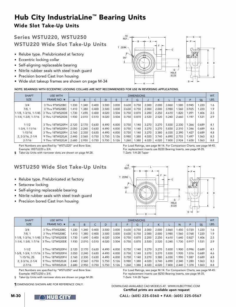
CALL: (605) 225-0360 • FAX: (605) 225-0567M-30
Hub City IndustriaLine™ Bearing Units
Certified prints are available upon requestDOWNLOAD AVAILABLE CAD MODELS AT: WWW.HUBCITYINC.COM
K
GHOLESIZE
C
F
A
S
DE
L N
P
T ZERK
B
.16REF.
30°
NOTE: BEARINGS WITH ECCENTRIC LOCKING COLLARS ARE NOT RECOMMENDED FOR USE IN REVERSING APPLICATIONS.
Part Numbers are specified by “WSTU250” and Bore Size. Example: WSTU250 x 3/4.§ Take-Up Units with narrower slots are shown on page M-28.
For Load Ratings, see page M-14. For Comparison Charts, see page M-45. For replacement inserts use B250 Bearing Inserts, see page M-35. T-Zerk: 1/4-28 Taper
S
DE
N
P
K
GHOLESIZE
C
F
A
L
T ZERK
B
.16REF.
30°
¶ DIMENSIONS SHOWN ARE FOR REFERENCE ONLY.
• Relube type. Prelubricated at factory• Eccentric locking collar• Self-aligning replaceable bearing• Nitrile rubber seals with steel trash guard• Precision bored Cast Iron housing• Wide slot takeup frames are shown on page M-34
• Relube type. Prelubricated at factory• Setscrew locking• Self-aligning replaceable bearing• Nitrile rubber seals with steel trash guard• Precision bored Cast Iron housing
Part Numbers are specified by “WSTU220” and Bore Size. Example: WSTU220 x 3/4.§ Take-Up Units with narrower slots are shown on page M-28.
For Load Ratings, see page M-14. For Comparison Charts, see page M-45. For replacement inserts use B220 Bearing Inserts, see page M-35. T-Zerk: 1/4-28 Taper
Wide Slot Take-Up Units
Series WSTU220, WSTU250WSTU220 Wide Slot Take-Up Units
WSTU250 Wide Slot Take-Up Units
SHAFT USE WITH DIMENSIONS WT. SIZE FRAME NO. H A B C D E F G J K L N P S§ LBS.
3/4 3 Thru 9TWS20BC 1.330 1.340 0.400 3.500 3.000 0.630 0.750 2.000 2.000 3.860 1.580 0.945 1.220 1.6 7/8, 1 3 Thru 9TWS20BC 1.410 1.380 0.400 3.500 3.000 0.630 0.750 2.000 2.000 3.980 1.560 0.925 1.220 1.9 1-1/8, 1-3/16, 1-1/4S 3 Thru 12TWS20DE 1.730 1.690 0.400 4.020 3.504 0.750 0.870 2.200 2.250 4.610 1.820 1.091 1.406 2.5 1-1/4, 1-3/8, 1-7/16 3 Thru 12TWS20DE 1.930 2.010 0.510 4.020 3.504 0.750 0.870 2.520 2.520 5.240 2.660 1.197 1.531 2.9
1-1/2 3 Thru 18TWS20FH 2.120 2.170 0.630 4.490 4.000 0.750 1.140 3.270 3.270 5.830 2.330 1.366 0.689 4.1 1-3/4, 1-11/16 3 Thru 18TWS20FH 2.050 2.240 0.630 4.490 4.000 0.750 1.140 3.270 3.270 5.830 2.310 1.346 0.689 4.6 1-15/16 3 Thru 18TWS20FH 2.160 2.330 0.630 4.490 4.000 0.750 1.140 3.270 3.380 6.030 2.390 1.427 0.689 4.8 2, 2-3/16, 2-1/4 9 Thru 18TWS20JK 2.440 2.560 0.750 5.750 5.126 0.980 1.380 4.020 3.740 6.890 2.755 1.497 1.063 8.3 2-7/16 9 Thru 18TWS20JK 2.680 2.950 0.750 5.750 5.126 1.260 1.380 4.020 4.020 7.800 2.924 1.658 1.063 8.8
SHAFT USE WITH DIMENSIONS WT. SIZE FRAME NO. H A B C D E F G J K L N P S§ LBS.
3/4 3 Thru 9TWS20BC 1.330 1.340 0.400 3.500 3.000 0.630 0.750 2.000 2.000 3.860 1.450 0.720 1.220 1.6 7/8, 1 3 Thru 9TWS20BC 1.410 1.380 0.400 3.500 3.000 0.630 0.750 2.000 2.000 3.980 1.560 0.768 1.220 1.9 1-1/8, 1-3/16, 1-1/4S 3 Thru 12TWS20DE 1.730 1.690 0.400 4.020 3.504 0.750 0.870 2.200 2.250 4.610 1.640 0.827 1.406 2.5 1-1/4, 1-3/8, 1-7/16 3 Thru 12TWS20DE 1.930 2.010 0.510 4.020 3.504 0.750 0.870 2.520 2.520 5.240 1.730 0.917 1.531 2.9
1-1/2 3 Thru 18TWS20FH 2.120 2.170 0.630 4.490 4.000 0.750 1.140 3.270 3.270 5.830 1.900 0.996 0.689 4.1 1-5/8, 1-3/4, 1-11/16 3 Thru 18TWS20FH 2.050 2.240 0.630 4.490 4.000 0.750 1.140 3.270 3.270 5.830 1.920 1.016 0.689 4.6 1-15/16, 2S 3 Thru 18TWS20FH 2.160 2.330 0.630 4.490 4.000 0.750 1.140 3.270 3.380 6.030 1.990 1.087 0.689 4.8 2, 2-3/16, 2-1/4 9 Thru 18TWS20JK 2.440 2.560 0.750 5.750 5.126 0.980 1.380 4.020 3.740 6.890 2.340 1.280 1.063 8.3 2-7/16 9 Thru 18TWS20JK 2.680 2.950 0.750 5.750 5.126 1.260 1.380 4.020 4.020 7.800 2.440 1.378 1.063 8.8

M-31
Hub City IndustriaLine™ Bearing Units
M
IndustriaLine
™ Bearing
s
Certified prints are available upon requestDOWNLOAD AVAILABLE CAD MODELS AT: WWW.HUBCITYINC.COM
EMAIL: [email protected] • www.hubcityinc.com
K
GHOLESIZE
C
F
A
S
DE
L N
P
T ZERK
B
.16REF.
30°
K
GHOLESIZE
C
F
A
S
DE
L N
P
T ZERK
B
.16REF.
30°
NOTE: BEARINGS WITH ECCENTRIC LOCKING COLLARS ARE NOT RECOMMENDED FOR USE IN REVERSING APPLICATIONS.
Part Numbers are specified by “WSTU250W” and Bore Size. Example: WSTU250W x 3/4.§ Take-Up Units with narrower slots are shown on page M-29.
For Load Ratings, see page M-14. For Comparison Charts, see page M-45. For replacement inserts use YW250 Bearing Inserts, see page M-36. T-Zerk: 1/4-28 Taper
¶ DIMENSIONS SHOWN ARE FOR REFERENCE ONLY.
• Relube type. Prelubricated at factory• Eccentric locking collar• Self-aligning replaceable bearing• Nitrile rubber seals with steel flingers• Precision bored Cast Iron housing• Wide slot take up frames are shown on
page M-34
• Relube type. Prelubricated at factory• Setscrew locking• Self-aligning replaceable bearing• Nitrile rubber seals with steel flingers• Precision bored Cast Iron housing
Part Numbers are specified by “WSTU220W” and Bore Size. Example: WSTU220W x 3/4.§ Take-Up Units with narrower slots are shown on page M-29.
For Load Ratings, see page M-14. For Comparison Charts, see page M-45. For replacement inserts use YW220 Bearing Inserts, see page M-36. T-Zerk: 1/4-28 Taper
Wide Slot Take-Up Units
Series WSTU220W, WSTU250WWSTU220W Wide Slot Take-Up Units
WSTU250W Wide Slot Take-Up Units
SHAFT USE WITH DIMENSIONS WT. SIZE FRAME NO. H A B C D E F G J K L N P S§ LBS.
7/8, 1 3 Thru 9TWS20BC 1.410 1.380 0.400 3.500 3.000 0.630 0.750 2.000 2.000 3.980 1.690 1.061 1.220 1.9
1-1/8, 1-3/16, 1-1/4S 3 Thru 12TWS20DE 1.730 1.690 0.400 4.020 3.504 0.750 0.870 2.200 2.250 4.610 1.920 1.187 1.406 2.5
1-1/4, 1-3/8, 1-7/16 3 Thru 12TWS20DE 1.930 2.010 0.510 4.020 3.504 0.750 0.870 2.520 2.520 5.240 1.996 1.270 1.531 2.9
1-1/2 3 Thru 18TWS20FH 2.120 2.170 0.630 4.490 4.000 0.750 1.140 3.270 3.270 5.830 2.337 1.373 0.689 4.1
1-3/4, 1-11/16 3 Thru 18TWS20FH 2.050 2.240 0.630 4.490 4.000 0.750 1.140 3.270 3.270 5.830 2.337 1.373 0.689 4.6
1-15/16 3 Thru 18TWS20FH 2.160 2.330 0.630 4.490 4.000 0.750 1.140 3.270 3.380 6.030 2.470 1.500 0.689 4.8
2, 2-3/16, 2-1/4 9 Thru 18TWS20JK 2.440 2.560 0.750 5.750 5.126 0.980 1.380 4.020 3.740 6.890 2.980 1.717 1.063 8.3
2-7/16 9 Thru 18TWS20JK 2.680 2.950 0.750 5.750 5.126 1.260 1.380 4.020 4.020 7.800 3.110 1.844 1.063 8.8
SHAFT USE WITH DIMENSIONS WT. SIZE FRAME NO. H A B C D E F G J K L N P S§ LBS.
3/4 3 Thru 9TWS20BC 1.330 1.340 0.400 3.500 3.000 0.630 0.750 2.000 2.000 3.860 1.350 0.720 1.220 1.6 7/8, 1 3 Thru 9TWS20BC 1.410 1.380 0.400 3.500 3.000 0.630 0.750 2.000 2.000 3.980 1.414 0.780 1.220 1.9 1-1/8, 1-3/16, 1-1/4S 3 Thru 12TWS20DE 1.730 1.690 0.400 4.020 3.504 0.750 0.870 2.200 2.250 4.610 1.600 0.874 1.406 2.5 1-1/4, 1-3/8, 1-7/16 3 Thru 12TWS20DE 1.930 2.010 0.510 4.020 3.504 0.750 0.870 2.520 2.520 5.240 1.730 1.000 1.531 2.9
1-1/2 3 Thru 18TWS20FH 2.120 2.170 0.630 4.490 4.000 0.750 1.140 3.270 3.270 5.830 2.150 1.189 0.689 4.1 1-3/4, 1-11/16 3 Thru 18TWS20FH 2.050 2.240 0.630 4.490 4.000 0.750 1.140 3.270 3.270 5.830 2.150 1.189 0.689 4.6 1-15/16, 2S 3 Thru 18TWS20FH 2.160 2.330 0.630 4.490 4.000 0.750 1.140 3.270 3.380 6.030 2.250 1.283 0.689 4.8 2, 2-3/16, 2-1/4 9 Thru 18TWS20JK 2.440 2.560 0.750 5.750 5.126 0.980 1.380 4.020 3.740 6.890 2.580 1.315 1.063 8.3 2-7/16 9 Thru 18TWS20JK 2.680 2.950 0.750 5.750 5.126 1.260 1.380 4.020 4.020 7.800 2.823 1.566 1.063 8.8

CALL: (605) 225-0360 • FAX: (605) 225-0567M-32
Hub City IndustriaLine™ Bearing Units
Certified prints are available upon requestDOWNLOAD AVAILABLE CAD MODELS AT: WWW.HUBCITYINC.COM
• Three bolt base mounting
• Welded steel construction
• Plated adjusting screw
Protected Screw Take-Up Frames are designed for use with:PB220, PB221, PB220W, PB221W, PB220HW and PB221HW Pillow Blocks.PB250, PB251, PB250W, PB251W, PB250HW and PB251HW Pillow Blocks.PB350 and PB350H Pillow Blocks.
* “C” dimension is obtained by adding “H” in the table above to “A” from Pillow Block Dimension tables.
The first digit of the part number represents the nominal adjustment which is possible. Because of the dimensional differences of the various Pillow Blocks, this adjustment varies according to the specifications noted below.
Actual Amount of Adjustment
SHAFT FRAME PART NUMBER
SIZE 6T210BC-3 9T210BC-3 6T210DH-3 9T210DH-3 12T210DH-3 18T210DH-3 12T210JK-3 18T210JK-3
WHEN USED WITH 200 SERIES PILLOW BLOCKS
WHEN USED WITH 350 SERIES PILLOW BLOCKS
3/4 6.375 9.375 — — — — — —
13/16 - 1 6.000 9.000 — — — — — —
1-1/16 - 1-3/16 — — 6.375 10.813 12.375 19.813 — —
1-1/4 - 1-7/16 — — 6.000 10.438 12.000 19.438 — —
1-1/2 - 1-9/16 — — 5.563 10.000 11.563 19.000 — —
1-5/8 - 1-3/4 — — 5.188 9.625 11.188 18.625 — —
1-13/16 - 2S — — 4.563 9.000 10.563 18.000 — —
2 - 2-3/16 — — — — — — 12.750 18.750 2-1/4 - 2-7/16 — — — — — — 12.000 18.000
1-7/16 — — 6.625 11.063 12.625 20.063 — —
1-1/2 - 1-3/4 — — 6.125 10.563 — — 14.688 20.688 1-15/16 - 2-15/16 — — 5.625 10.063 — — 14.188 20.188 2-3/16 - 2-1/4 — — — — — — 13.563 19.563 2-7/16 - 2-1/2 — — — — — — 12.813 18.813
BOLT SIZE
LB2B1
ADJUSTMENT
CH
QR
A W
G
TS
J1 J2
PART SHAFT DIMENSIONS BOLT WT. NUMBER SIZE L W A B1 B2 G H J1 J2 Q R S T SIZE LBS.
6T210BC-3 3/4 - 1 17.125 3.250 2.250 13.875 15.875 3.313 2.375 0.438 0.563 1.750 0.563 0.625 0.188 0.375 6.0 9T210BC-3 3/4 - 1 20.125 3.250 2.250 16.875 18.875 3.313 2.375 0.438 0.563 1.750 0.563 0.625 0.188 0.375 6.7 6T210DH-3 1-1/16 - 2S 18.188 3.750 2.500 15.438 16.938 3.375 2.813 0.438 0.563 2.313 0.875 0.750 0.188 0.500 8.9 9T210DH-3 1-1/16 - 2S 22.625 3.750 2.500 19.875 21.375 3.375 2.813 0.438 0.563 2.313 0.875 0.750 0.188 0.500 10.3 12T210DH-3 1-1/16 - 2S 24.188 3.750 2.500 21.4.8 22.938 3.375 2.813 0.438 0.563 2.313 0.875 0.750 0.188 0.500 10.9 18T210DH-3 1-1/16 - 2S 31.625 3.750 2.500 28.875 30.375 3.375 2.813 0.438 0.563 2.313 0.875 0.750 0.188 0.500 13.3 12T210JK-3 2 - 2-7/16 28.000 4.750 3.000 24.750 26.750 4.000 3.313 0.563 0.688 2.625 1.438 1.000 0.250 0.625 18.3 18T210JK-3 2 - 2-7/16 34.000 4.750 3.000 30.750 32.750 4.000 3.313 0.563 0.688 2.625 1.438 1.000 0.250 0.625 21.2
¶ DIMENSIONS SHOWN ARE FOR REFERENCE ONLY.
Take-Up Frames
Series T210Protected Screw Take-Up Frames

M-33
Hub City IndustriaLine™ Bearing Units
M
IndustriaLine
™ Bearing
s
Certified prints are available upon requestDOWNLOAD AVAILABLE CAD MODELS AT: WWW.HUBCITYINC.COM
EMAIL: [email protected] • www.hubcityinc.com
BW
S
C*U*
ADJ
A D
B E
GT
KH
L
ONLY CENTER HOLETHIS END ON T200BC& T200DE FRAMES.
TWO OUTERHOLES THIS ENDON T200FH &T200JK FRAMES.
JBOLT
HOLES
• Welded steel construction
• Plated adjusting screw
These Take-Up Frames are used with TU220, TU250, TU220W and TU250W Take-Up Units shown on pages M-28 and M-29 and with TU350 Take-Up Units shown on page M-40.*NOTE — “U” may have more than one value, depending on the Take-Up Unit and Frame combination used, therefore determine “U” from frame dimensions “G” minus “C” plus Take-Up Unit dimensions “A”, “C” and “F”.
¶ DIMENSIONS SHOWN ARE FOR REFERENCE ONLY.
Take-Up Frames
Series T200T200 Side Mounting Take-Up Frames
SHAFT SIZE RANGE DIMENSIONS (J) BOLT HOLES PART FOR “200” FOR “300” ADJUST- H WT. NUMBER SERIES UNITS SERIES UNITS MENT L W A B C D E G MAX. K S T NO. SIZE LBS.
3T200BC 3/4 - 1 3.000 8.500 4.188 7.500 3.188 0.500 0.500 3.063 1.500 2.297 1.375 0.625 0.250 3.000 0.563 3.6
6T200BC 3/4 - 1 6.000 11.500 4.188 10.500 3.188 0.500 0.500 3.063 1.500 2.297 1.375 0.625 0.250 3.000 0.563 4.4
9T200BC 3/4 - 1 9.000 14.500 4.188 13.500 3.188 0.500 0.500 3.063 1.500 2.297 1.375 0.625 0.250 3.000 0.563 5.5
3T200DE 1-1/16 - 1-7/16 3.000 9.375 4.688 8.375 3.688 0.500 0.500 3.563 1.500 2.531 1.375 0.750 0.250 3.000 0.563 4.3
6T200DE 1-1/16 - 1-7/16 6.000 12.375 4.688 11.375 3.688 0.500 0.500 3.563 1.500 2.531 1.375 0.750 0.250 3.000 0.563 5.3
9T200DE 1-1/16 - 1-7/16 9.000 15.375 4.688 14.375 3.688 0.500 0.500 3.563 1.500 2.531 1.375 0.750 0.250 3.000 0.563 6.3
12T200DE 1-1/16 - 1-7/16 12.000 18.375 4.688 17.375 3.688 0.500 0.500 3.563 1.500 2.531 1.375 0.750 0.250 3.000 0.563 7.4
3T200FH 1-1/2 - 2S 1-7/16 - 1-3/4 3.000 11.000 5.188 9.875 3.063 0.500 0.625 4.063 2.000 2.938 1.625 1.000 0.250 4.000 0.563 6.3
6T200FH 1-1/2 - 2S 1-7/16 - 1-3/4 6.000 14.000 5.188 12.875 3.063 0.500 0.625 4.063 2.000 2.938 1.625 1.000 0.250 4.000 0.563 7.6
9T200FH 1-1/2 - 2S 1-7/16 - 1-3/4 9.000 17.000 5.188 15.875 3.063 0.500 0.625 4.063 2.000 2.938 1.625 1.000 0.250 4.000 0.563 9.1
12T200FH 1-1/2 - 2S 1-7/16 - 1-3/4 12.000 20.000 5.188 18.875 3.063 0.500 0.625 4.063 2.000 2.938 1.625 1.000 0.250 4.000 0.563 10.5
18T200FH 1-1/2 - 2S 1-7/16 - 1-3/4 18.000 26.000 5.188 24.875 3.063 0.500 0.625 4.063 2.000 2.938 1.625 1.000 0.250 4.000 0.563 13.2
9T200JK 2 - 2-7/16 1-15/16 - 2-3/16 9.000 18.250 6.375 16.875 4.125 0.625 0.750 5.250 2.000 3.438 1.875 1.250 0.3125 4.000 0.688 13.9
12T200JK 2 - 2-7/16 1-15/16 - 2-3/16 12.000 21.250 6.375 19.875 4.125 0.625 0.750 5.250 2.000 3.438 1.875 1.250 0.3125 4.000 0.688 15.0
18T200JK 2 - 2-7/16 1-15/16 - 2-3/16 18.000 27.250 6.375 25.875 4.125 0.625 0.750 5.250 2.000 3.438 1.875 1.250 0.3125 4.000 0.688 19.8

CALL: (605) 225-0360 • FAX: (605) 225-0567M-34
Hub City IndustriaLine™ Bearing Units
Certified prints are available upon requestDOWNLOAD AVAILABLE CAD MODELS AT: WWW.HUBCITYINC.COM
Take-Up Frames
Series TWS200TWS200 Wide Slot Take-Up Frames
These Take-Up Frames are used with WSTU220, WSTU250, WSTU220W and WSTU250W Take-Up Units shown on pages M-30 and M-31 and with WSTU350 Take-Up Units shown on page M-41.*NOTE — “U” may have more than one value, depending on the Take-Up Unit and Frame combination used, therefore determine “U” from frame dimensions “G” minus “C” plus Take-Up Unit dimensions “A”, “C” and “F”.
¶ DIMENSIONS SHOWN ARE FOR REFERENCE ONLY.
HMAX,
GT
K
LA
S
BW
C D
*U* ADJUSTMENTJ
BOLTHOLES
ONLY CENTER HOLETHIS END ON TWS200AC& TWS200DE FRAMES.
ONLY TWO OUTERHOLES THIS ENDON TWS200FH &TWS200JK FRAMES.
E
• Welded steel construction
• Plated adjusting screw
SHAFT SIZE RANGE DIMENSIONS (J) BOLT HOLES PART FOR “200” FOR “300” ADJUST- H WT. NUMBER SERIES UNITS SERIES UNITS MENT L W A B C D E G MAX. K S T NO. SIZE LBS.
1TWS200AC 1/2 - 1 1-1/2 7.000 4.063 6.000 3.188 .500 .500 3.063 1.500 2.438 1.375 .625 .250 3 .563 3.3
3TWS200AC 1/2 - 1 3 8.500 4.063 7.500 3.188 .500 .500 3.063 1.500 2.438 1.375 .625 .250 3 .563 3.9
6TWS200AC 1/2 - 1 6 11.500 4.063 1.500 3.188 .500 .500 3.063 1.500 2.438 1.375 .625 .250 3 .563 5.1
9TWS200AC 1/2 - 1 9 14.500 4.063 13.500 3.188 .500 .500 3.063 1.500 2.438 1.375 .625 .250 3 .563 6.2
3TWS200DE 1-1/8 - 1-7/16 1 - 1-1/4 3 9.500 4.688 8.375 3.688 .500 .500 3.563 1.500 2.656 1.375 .750 .250 3 .563 5.4
6TWS200DE 1-1/8 - 1-7/16 1 - 1-1/4 6 12.500 4.688 11.375 3.688 .500 .500 3.563 1.500 2.656 1.375 .750 .250 3 .563 6.7
9TWS200DE 1-1/8 - 1-7/16 1 - 1-1/4 9 15.500 4.688 14.375 3.688 .500 .500 3.563 1.500 2.656 1.375 .750 .250 3 .563 8.1
12TWS200DE 1-1/8 - 1-7/16 1 - 1-1/4 12 18.500 4.688 17.375 3.688 .500 .500 3.563 1.500 2.656 1.375 .750 .250 3 .563 9.5
3TWS200FH 1-1/2 - 2S 1-7/16 - 1-3/4 3 11.500 5.063 9.875 3.063 1.00 .625 4.063 2.000 3.125 1.625 1.000 .250 4 .563 7.4
6TWS200FH 1-1/2 - 2S 1-7/16 - 1-3/4 6 14.500 5.063 12.875 3.063 1.00 .625 4.063 2.000 3.125 1.625 1.000 .250 4 .563 9.1
9TWS200FH 1-1/2 - 2S 1-7/16 - 1-3/4 9 17.500 5.063 15.875 3.063 1.00 .625 4.063 2.000 3.125 1.625 1.000 .250 4 .563 10.8
12TWS200FH 1-1/2 - 2S 1-7/16 - 1-3/4 12 20.500 5.063 18.875 3.063 1.00 .625 4.063 2.000 3.125 1.625 1.000 .250 4 .563 12.5
18TWS200FH 1-1/2 - 2S 1-7/16 - 1-3/4 18 24.500 5.063 24.875 3.063 1.00 .625 4.063 2.000 3.125 1.625 1.000 .250 4 .563 15.9
9TWS200JK 2 - 2-7/16 1-15/16 - 2-3/16 9 18.250 6.313 16.875 4.125 .625 .750 5.188 2.000 3.719 1.875 1.250 .313 4 .688 20.0
12TWS200JK 2 - 2-7/16 1-15/16 - 2-3/16 12 21.250 6.313 19.875 4.125 .625 .750 5.188 2.000 3.719 1.875 1.250 .313 4 .688 22.8
18TWS200JK 2 - 2-7/16 1-15/16 - 2-3/16 18 27.250 6.313 25.875 4.125 .625 .750 5.188 2.000 3.719 1.875 1.250 .313 4 .688 28.2

M-35
Hub City IndustriaLine™ Bearing Units
M
IndustriaLine
™ Bearing
s
Certified prints are available upon requestDOWNLOAD AVAILABLE CAD MODELS AT: WWW.HUBCITYINC.COM
EMAIL: [email protected] • www.hubcityinc.com
(1) SETSCREW
C
M
W
DS
W
(2) SETSCREWS@ 120°
M
C S D
• Spherical outside diameter
• Relube type. Prelubricated at factory
• Molded glass fiber reinforced polyamide retainer
• Nitrile rubber seals with steel trash guard
• Eccentric locking collar
Part Numbers are specified by “B220” and Bore Size. Example B220 x 1-1/4.
Used in PB220, PB221 Pillow Blocks; FB220, FB230 Flange Blocks; and TU220, WSTU220 Take-Up Units.
Part Numbers are specified by “B250” and Bore Size. Example B250 x 1-1/4.
Used in PB100, PB100L, PB150, PB150L, PB250, PB251, TPB250 Pillow Blocks; FB100, FB110, FB150, FB160, FB250, FB260 Flange Blocks; and TU250, WSTU250
Take-Up Units.
• Spherical outside diameter
• Relube type. Prelubricated at factory
• Molded glass fiber reinforced polyamide retainer
• Nitrile rubber seals with steel trash guard
• Setscrew Locking
NOTE: BEARINGS WITH ECCENTRIC LOCKING COLLARS ARE NOT RECOMMENDED FOR USE IN REVERSING APPLICATIONS.
Bearing Inserts
¶ DIMENSIONS SHOWN ARE FOR REFERENCE ONLY.
Series B220, B250B220 Bearing Inserts
B250 Bearing Inserts
DIMENSIONS WT. SHAFT SIZE C D M S W SETSCREW LBS.
1/2, 5/8 1.071 1.5748 0.870 1.126 0.472 1/4-28 UNF 0.2 3/4 1.275 1.8504 0.925 1.220 0.551 1/4-28 UNF 0.3 7/8, 1 1.472 2.0472 0.925 1.220 0.592 1/4-28 UNF 0.4 1-1/8, 1-3/16, 1-1/4s 1.736 2.4409 1.051 1.406 0.709 5/16-24 UNF 0.6 1-1/4, 1-3/8, 1-7/16 2.012 2.8346 1.157 1.531 0.748 3/8-24 UNF 1.0 1-1/2 2.224 3.1496 1.268 1.720 0.827 3/8-24 UNF 1.3 1-11/16, 1-3/4 2.441 3.3465 1.287 1.720 0.866 3/8-24 UNF 1.6 1-15/16, 2S 2.645 3.5433 1.287 1.720 0.866 3/8-24 UNF 1.7 2, 2-3/16 2.933 3.9370 1.439 1.911 0.984 7/16-20 UNF 2.4 2-7/16 3.228 4.3307 1.559 2.091 1.024 7/16-20 UNF 3.0
DIMENSIONS WT. SHAFT SIZE C D M S W SETSCREW LBS.
1/2, 5/8 .953 1.5748 0.626 0.870 0.472 10-32 0.3 3/4 1.110 1.8504 0.720 1.004 0.551 1/4-28 UNF 0.3 7/8, 15/16, 1 1.328 2.0472 0.768 1.071 0.591 1/4-28 UNF 0.4 1-1/8, 1-3/16, 1-1/4s 1.563 2.4409 0.827 1.189 0.709 1/4-28 UNF 0.6 1-1/4, 1-3/8, 1-7/16 1.815 2.8346 0.917 1.299 0.748 5/16-24 UNF 0.9 1-1/2 2.039 3.1496 0.996 1.417 0.827 5/16-24 UNF 1.5 1-11/16, 1-3/4 2.236 3.3465 1.016 1.457 0.866 5/16-24 UNF 1.8 1-15/16, 2S 2.461 3.5433 1.087 1.528 0.866 3/8-24 UNF 1.8 2, 2-3/16 2.719 3.9370 1.280 1.772 0.984 3/8-24 UNF 2.4 2-1/4, 2-7/16 2.978 4.3307 1.378 1.909 1.024 3/8-24 UNF 2.9 2-15/16 3.624 5.1181 1.535 2.106 1.142 3/8-24 UNF 4.9

CALL: (605) 225-0360 • FAX: (605) 225-0567M-36
Hub City IndustriaLine™ Bearing Units
Certified prints are available upon requestDOWNLOAD AVAILABLE CAD MODELS AT: WWW.HUBCITYINC.COM
D
W
M(1) SETSCREW
C S
¶ DIMENSIONS SHOWN ARE FOR REFERENCE ONLY.
W
(2)SETSCREWS
@ 120°
M
DC S
• Spherical outside diameter
• Relube type. Prelubricated at factory
• Molded glass fiber reinforced polyamide retainer
• Nitrile rubber seals with steel flingers
• Metal flingers
• Setscrew locking
• Wide inner race
Part Numbers are specified by “YW220” and Bore Size. Example YW220 x 1-1/4.
Used in PB220W, PB221W, PB220HW, PB221HW Pillow Blocks; FB220HW, FB230HW Flange Blocks; and TU220W Take-Up Units.
Part Numbers are specified by “YW250” and Bore Size. Example YW250 x 1-1/4.
Used in PB250W, PB251W, PB250HW, PB251HW, TPB250W Pillow Blocks; FB250HW, FB260HW Flange Blocks; and TU250W Take-Up Units.
• Spherical outside diameter
• Relube type. Prelubricated at factory
• Molded glass fiber reinforced polyamide retainer
• Nitrile rubber seals with steel flingers
• Metal flingers
• Eccentric locking collar
• Wide inner race
DIMENSIONS WT. SHAFT SIZE C D M S W SETSCREW LBS.
1 1.472 2.0472 1.059 1.748 0.591 1/4-28 UNF 0.6 1-3/16 1.736 2.4409 1.185 1.906 0.709 5/16-24 UNF 0.8 1-1/4, 1-3/8, 1-7/16 2.012 2.8346 1.272 2.012 0.748 3/8-24 UNF 1.4 1-1/2 2.224 3.1496 1.374 2.217 0.827 3/8-24 UNF 1.7 1-11/16, 1-3/4 2.441 3.3465 1.374 2.217 0.866 3/8-24 UNF 1.9 1-15/16 2.646 3.5433 1.500 2.469 0.866 3/8-24 UNF 2.1 2, 2-3/16 2.933 3.9370 1.717 2.811 0.984 7/16-20 UNF 3.1 2-7/16 3.228 4.3307 1.838 3.063 1.024 7/16-20 UNF 4.4
DIMENSIONS WT. SHAFT SIZE C D M S W SETSCREW LBS. 5/8 0.953 1.5748 0.626 1.079 0.472 1/4-28 UNF 0.2 3/4 1.110 1.8504 0.720 1.220 0.551 1/4-28 UNF 0.3 1 1.328 2.0472 0.780 1.343 0.591 1/4-28 UNF 0.5 1-3/16, 1-1/4S 1.563 2.4409 0.874 1.500 0.709 1/4-28 UNF 0.7 1-1/4, 1-7/16 1.815 2.8346 1.000 1.689 0.748 5/16-24 UNF 1.0 1-1/2 2.039 3.1496 1.189 1.937 0.827 5/16-24 UNF 1.3 1-3/4 2.236 3.3465 1.189 1.937 0.866 5/16-24 UNF 1.6 1-15/16 2.461 3.5433 1.283 2.031 0.866 3/8-24 UNF 1.6 2 2.719 3.9370 1.315 2.189 0.984 3/8-24 UNF 2.5 2-7/16 2.978 4.3307 1.566 2.563 1.024 3/8-24 UNF 3.8
Bearing Inserts
Series YW220, YW250YW220 Bearing Inserts
YW250 Bearing Inserts

M-37
Hub City IndustriaLine™ Bearing Units
M
IndustriaLine
™ Bearing
s
Certified prints are available upon requestDOWNLOAD AVAILABLE CAD MODELS AT: WWW.HUBCITYINC.COM
EMAIL: [email protected] • www.hubcityinc.com
For ultimate life, snug fit or light press on shaft should be used.Maximum Recommended Speeds — 1“ and smaller 3500 RPM 1-3/16” - 1-7/16“ 3000 RPM 1-1/2“ -1-3/4“ 2500 RPM 1-15/16” - 2-1/4“ 2000 RPM 2-7/16“ and larger 1800 RPMRecommended Operating Temperature Range — 25° to + 225°F.For applications not covered in the table above, consult factory engineering.
BEARING RADIAL LOAD CAPACITY IN POUNDS BASED ON L-10 LIFE OF 500 HOURS AND STEADY LOAD CONDITIONS (2500 HOURS AVERAGE LIFE)
SHAFT BEARING SPEED – REVOLUTIONS PER MINUTE (RPM)
SIZE 100 500 1,000 1,500 2,000 2,500 3,000 3,500
1 3,040 1,780 1,410 1,230 1,120 1,040 980 930 1-3/16 3,980 2,330 1,850 1,610 1,470 1,360 1,280 — 1-7/16 4,790 2,800 2,220 1,940 1,760 1,640 1,540 — 1-1/2 5,180 3,030 2,400 2,100 1,910 1,770 — — 1-11/16, 1-3/4 5,480 3,200 2,540 2,220 2,020 1,870 — —
1-15/16, 2 6,800 3,980 3,160 2,760 2,510 — — 2-3/16, 2-1/4 8,250 4,830 3,830 3,350 3,040 — — — 2-7/16, 2-1/2 9,710 5,680 4,510 3,940 — — — — 2-11/16 10,330 6,040 4,790 4,190 — — — 2-15/16, 3 11,370 6,650 5,280 4,610 — — — — 3-7/16, 3-1/2 14,890 8,710 6,910 6,040 — — — —
TO MODIFY THE ABOVE RATINGS FOR OTHER L-10 LIFE REQUIREMENTS OR FOR SHOCK LOADS MULTIPLY THE ABOVE RATINGS BY THE FACTOR FROM THIS CHART MODIFICATION FACTORS FOR L-10 SERVICE LIFE AND LOAD CONDITIONS: L-10 LIFE (HOURS) LOAD CONDITIONS 500 700 1,000 1,500 2,000 3,000 4,000 5,000 7,000 10,000 15,000 20,000 30,000 50,000
Steady Load 1.00 .894 .794 .694 .630 .550 .500 .464 .415 .368 .322 .292 .255 .215 Light Shock .90 .804 .715 .624 .567 .495 .450 .418 .373 .331 .290 .263 .230 .194 Moderate Shock .70 .626 .556 .485 .441 .385 .350 .325 .290 .258 .225 .205 .179 .151
Series 350 - Ratings

CALL: (605) 225-0360 • FAX: (605) 225-0567M-38
Hub City IndustriaLine™ Bearing Units
Certified prints are available upon requestDOWNLOAD AVAILABLE CAD MODELS AT: WWW.HUBCITYINC.COM
H
FE MAX.E MIN.
B
A
C
DT ZERK M
S
LG
JBOLTSIZE
DIMENSIONS
SHAFT E WT. SIZE A B C D MIN. MAX. F G H J L M S LBS.
1 1.688 3.250 1.563 3.000 4.250 5.125 6.375 1.750 0.750 0.500 1.710 0.826 1.189 3.3 1-3/16 1.875 3.688 1.815 3.438 4.688 5.500 6.750 1.875 0.688 0.500 1.851 0.917 1.299 4.4 1-7/16 2.125 4.125 2.039 3.875 5.125 5.938 7.125 1.875 0.938 0.500 1.937 0.996 1.417 4.9 1-1/2 2.313 4.438 2.236 4.125 5.750 6.500 8.000 2.000 1.000 0.625 2.017 1.015 1.457 5.6 1-3/4 2.313 4.563 2.461 4.313 5.813 6.750 8.375 2.000 0.875 0.625 2.092 1.086 1.528 6.7 1-15/16, 2 2.500 5.000 2.719 4.750 6.375 7.433 9.000 2.250 0.938 0.625 2.406 1.280 1.772 8.5
2-3/16, 2-1/4 2.750 5.563 2.978 5.250 6.875 8.000 9.625 2.500 1.188 0.750 2.625 1.378 1.909 11.3 2-7/16, 2-1/2 3.000 6.125 3.427 6.000 7.750 8.750 10.500 2.750 1.125 0.750 2.938 1.457 2.008 15.2 2-11/16 3.500 6.750 3.624 6.250 8.000 9.500 11.250 3.000 1.375 0.875 3.031 1.535 2.106 17.9 2-15/16, 3 3.500 7.000 3.835 6.750 8.500 10.250 12.000 3.250 1.125 0.875 3.156 1.537 2.185 19.1 3-7/16, 3-1/2 4.000 8.000 4.394 7.688 9.688 12.563 14.563 3.500 1.125 0.875 3.328 1.555 2.244 28.4
• Relube type. Prelubricated at factory
• Setscrew locking
• Self-aligning replaceable bearing
• Nitrile rubber seals with steel trash guard
• Precision bored Cast Iron Housing
Part Numbers are specified by “PB350” and Bore Size. Example: PB350 x 2-7/16.For Load Ratings, see page M-37. For Comparison Charts, see page M-45.
For replacement inserts use B350 Bearing Inserts, see page M-41.T-Zerk: 1/4-28 Taper
Part Numbers are specified by “FB350” and Bore Size. Example: FB350 x 2-7/16.For Load Ratings, see page M-37. For Comparison Charts, see page M-46.
For replacement inserts use B350 Bearing Inserts, see page M-41.T-Zerk: 1/4-28 Taper
• Relube type. Prelubricated at factory
• Setscrew locking
• Self-aligning replacement bearing
• Nitrile rubber seals with steel trash guard
• Precision bored Cast Iron Housing B.C.J BOLT SIZE
E B
E
B
D C
HM
T ZERK
S
L
SHAFT
DIMENSIONS WT.
SIZE B B.C. C D E H J L M S LBS.
1 4.250 4.625 1.563 3.190 3.268 0.550 0.472 1.575 1.220 1.189 3.0 1-3/16 4.610 5.125 1.815 3.620 3.622 0.630 0.551 1.752 1.340 1.299 4.6 1-7/16 5.120 5.677 2.039 4.090 4.016 0.630 0.630 1.949 1.420 1.417 5.4 1-1/2 5.390 5.846 2.236 4.250 4.134 0.710 0.630 2.067 1.500 1.457 5.8 1-3/4 5.630 6.181 2.461 4.450 4.375 0.710 0.630 2.126 1.570 1.528 7.0 1-15/16, 2 6.380 7.236 2.719 4.920 5.180 0.780 0.748 2.264 1.690 1.772 9.2
2-3/16, 2-1/4 6.880 7.960 2.978 5.310 5.630 0.780 0.748 2.520 1.890 1.909 12.1 2-7/16, 2-1/2 7.370 8.296 3.427 6.090 5.866 0.830 0.748 2.796 2.320 2.008 15.4 2-11/16 7.750 8.463 3.624 6.380 5.984 0.940 0.906 2.992 2.360 2.106 18.3 2-15/16, 3 7.750 8.463 3.835 6.780 5.984 0.940 0.906 3.110 2.680 2.185 19.0 3-7/16, 3-1/2 8.430 9.520 4.394 7.690 6.732 0.940 0.906 3.130 2.750 2.244 22.2
¶ DIMENSIONS SHOWN ARE FOR REFERENCE ONLY.
Cast Iron Pillow Blocks
Cast Iron Flange Blocks
Series PB350
Series FB350

M-39
Hub City IndustriaLine™ Bearing Units
M
IndustriaLine
™ Bearing
s
Certified prints are available upon requestDOWNLOAD AVAILABLE CAD MODELS AT: WWW.HUBCITYINC.COM
EMAIL: [email protected] • www.hubcityinc.com
D
T ZERK
H
B
A
C
M
S
LG
JBOLTSIZE
F
E MAX.
E MIN.
DIMENSIONS
SHAFT E WT. SIZE A B C D MIN. MAX. F G H J L M S LBS.
1 1.688 3.156 1.563 2.938 4.250 5.125 6.063 1.500 0.688 0.500 1.585 0.826 1.189 2.0 1-3/16 1.875 3.563 1.815 3.375 4.625 5.500 6.438 1.500 0.625 0.500 1.663 0.917 1.299 2.8 1-7/16 2.125 4.000 2.039 3.750 5.063 6.313 7.375 1.750 0.688 0.500 1.874 0.996 1.417 4.3 1-1/2 2.313 4.313 2.236 4.000 5.563 6.688 7.875 2.000 0.813 0.625 2.018 1.015 1.457 5.1 1-3/4 2.313 4.438 2.461 4.250 5.813 6.688 7.875 2.125 0.875 0.625 2.154 1.086 1.528 5.3 1-15/16, 2 2.500 4.844 2.719 4.688 6.063 7.438 8.625 2.375 0.875 0.625 2.469 1.280 1.772 6.6
2-3/16, 2-1/4 2.750 5.344 2.978 5.188 6.688 7.813 9.250 2.625 0.938 0.750 2.688 1.378 1.909 8.6 2-7/16, 2-1/2 3.000 5.938 3.427 5.875 7.438 8.563 10.000 2.875 0.938 0.750 2.891 1.457 2.008 12.4 2-11/16 3.500 6.563 3.624 6.125 8.313 9.688 11.313 3.000 1.000 0.875 3.031 1.535 2.106 15.3 2-15/16, 3 3.500 6.750 3.835 6.500 8.313 9.688 11.313 3.125 1.000 0.875 3.094 1.537 2.185 15.8 3-7/16, 3-1/2 4.000 7.688 4.394 7.375 9.688 12.563 14.188 3.500 1.188 0.875 3.328 1.555 2.244 23.3
Part Numbers are specified by “PB350H” and Bore Size. Example: PB350H x 2-7/16.For Load Ratings, see page M-37. For Comparison Charts, see page M-45.
For replacement inserts use B350 Bearing Inserts, see page M-41.T-Zerk: 1/4-28 Taper
Part Numbers are specified by “FB350H” and Bore Size. Example: FB350H x 2-7/16.For Load Ratings, see page M-37. For Comparison Charts, see page M-46.
For replacement inserts use B350 Bearing Inserts, see page M-41.T-Zerk: 1/4-28 Taper
SHAFT DIMENSIONS WT. SIZE B B.C. C D E H J L M S LBS.
1 4.250 4.596 1.563 3.190 3.250 0.510 0.472 1.263 1.180 1.189 3.0000 1-3/16 4.610 5.125 1.815 3.620 3.625 0.560 0.630 1.350 1.340 1.299 4.2000 1-7/16 5.120 5.656 2.039 4.090 4.000 0.560 0.630 1.528 1.500 1.417 5.4000 1-1/2 5.390 5.834 2.236 4.250 4.125 0.560 0.748 1.566 1.570 1.457 5.8000 1-3/4 5.630 6.187 2.461 4.450 4.375 0.560 0.748 1.677 1.570 1.528 7.0000 1-15/16, 2 6.380 7.250 2.719 4.920 5.125 0.790 0.748 1.922 1.730 1.772 9.2000
2-3/16, 2-1/4 6.890 7.954 2.978 5.310 5.625 0.790 0.748 2.051 1.930 1.909 12.1000 2-7/16, 2-1/2 7.360 8.308 3.427 6.100 5.875 0.830 0.748 2.158 2.320 2.080 15.4000 2-11/16 7.750 8.485 3.624 6.380 6.000 0.940 0.906 2.252 2.360 2.106 18.3000 2-15/16, 3 7.750 8.485 3.835 6.770 6.000 0.940 0.906 2.449 2.680 2.185 19.0000 3-7/16, 3-1/2 8.420 9.546 4.394 7.680 6.750 0.940 0.906 2.255 2.750 2.244 22.2000
B.C.J BOLT SIZE
E B
E
B
D C
HM
T ZERK
S
L
¶ DIMENSIONS SHOWN ARE FOR REFERENCE ONLY.
• Relube type. Prelubricated at factory
• Setscrew locking
• Self-aligning replacement bearing
• Nitrile rubber seals with steel trash guard
• Precision bored HUB-ALLOY® housing
• Higher strength and greater impact resistance than
gray iron for high shock loads
• Relube type. Prelubricated at factory
• Setscrew locking
• Self-aligning replacement bearing
• Nitrile rubber seals with steel trash guard
• Precision bored HUB-ALLOY® housing
• Higher strength and greater impact resistance than gray iron for high shock loads
Hub-Alloy® Pillow Blocks
Hub-Alloy® Flange Blocks
Series PB350H
Series FB350H
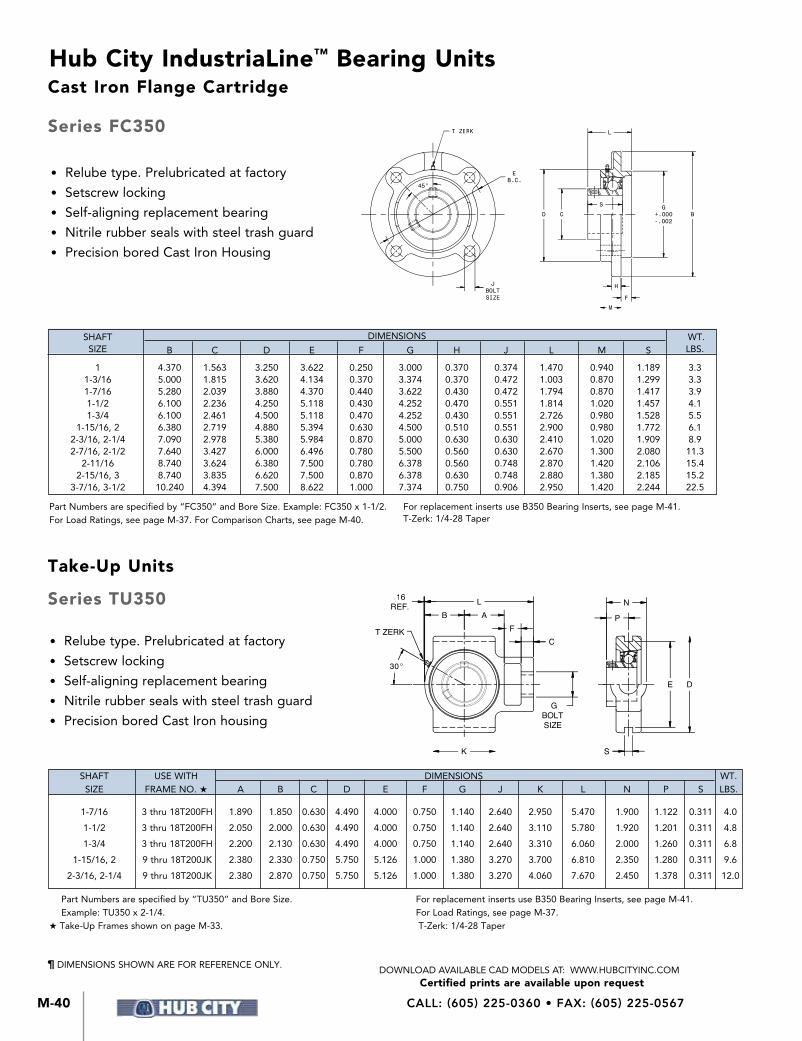
CALL: (605) 225-0360 • FAX: (605) 225-0567M-40
Hub City IndustriaLine™ Bearing Units
Certified prints are available upon requestDOWNLOAD AVAILABLE CAD MODELS AT: WWW.HUBCITYINC.COM
AL
B
CF
GBOLTSIZE
K
.16REF.
T ZERK
S
DE
N
P
30°
45°
JBOLTSIZE
EB.C.
T ZERK
H
F
M
G+.000-.002
B
L
CD
S
Part Numbers are specified by “FC350” and Bore Size. Example: FC350 x 1-1/2.For Load Ratings, see page M-37. For Comparison Charts, see page M-40.
For replacement inserts use B350 Bearing Inserts, see page M-41.T-Zerk: 1/4-28 Taper
Part Numbers are specified by “TU350” and Bore Size. Example: TU350 x 2-1/4.
HTake-Up Frames shown on page M-33.
For replacement inserts use B350 Bearing Inserts, see page M-41. For Load Ratings, see page M-37. T-Zerk: 1/4-28 Taper
• Relube type. Prelubricated at factory
• Setscrew locking
• Self-aligning replacement bearing
• Nitrile rubber seals with steel trash guard
• Precision bored Cast Iron housing
• Relube type. Prelubricated at factory
• Setscrew locking
• Self-aligning replacement bearing
• Nitrile rubber seals with steel trash guard
• Precision bored Cast Iron Housing
SHAFT DIMENSIONS WT. SIZE B C D E F G H J L M S LBS.
1 4.370 1.563 3.250 3.622 0.250 3.000 0.370 0.374 1.470 0.940 1.189 3.3 1-3/16 5.000 1.815 3.620 4.134 0.370 3.374 0.370 0.472 1.003 0.870 1.299 3.3 1-7/16 5.280 2.039 3.880 4.370 0.440 3.622 0.430 0.472 1.794 0.870 1.417 3.9 1-1/2 6.100 2.236 4.250 5.118 0.430 4.252 0.470 0.551 1.814 1.020 1.457 4.1 1-3/4 6.100 2.461 4.500 5.118 0.470 4.252 0.430 0.551 2.726 0.980 1.528 5.5 1-15/16, 2 6.380 2.719 4.880 5.394 0.630 4.500 0.510 0.551 2.900 0.980 1.772 6.1 2-3/16, 2-1/4 7.090 2.978 5.380 5.984 0.870 5.000 0.630 0.630 2.410 1.020 1.909 8.9 2-7/16, 2-1/2 7.640 3.427 6.000 6.496 0.780 5.500 0.560 0.630 2.670 1.300 2.080 11.3 2-11/16 8.740 3.624 6.380 7.500 0.780 6.378 0.560 0.748 2.870 1.420 2.106 15.4 2-15/16, 3 8.740 3.835 6.620 7.500 0.870 6.378 0.630 0.748 2.880 1.380 2.185 15.2 3-7/16, 3-1/2 10.240 4.394 7.500 8.622 1.000 7.374 0.750 0.906 2.950 1.420 2.244 22.5
SHAFT USE WITH DIMENSIONS WT. SIZE FRAME NO. H A B C D E F G J K L N P S LBS.
1-7/16 3 thru 18T200FH 1.890 1.850 0.630 4.490 4.000 0.750 1.140 2.640 2.950 5.470 1.900 1.122 0.311 4.0
1-1/2 3 thru 18T200FH 2.050 2.000 0.630 4.490 4.000 0.750 1.140 2.640 3.110 5.780 1.920 1.201 0.311 4.8
1-3/4 3 thru 18T200FH 2.200 2.130 0.630 4.490 4.000 0.750 1.140 2.640 3.310 6.060 2.000 1.260 0.311 6.8
1-15/16, 2 9 thru 18T200JK 2.380 2.330 0.750 5.750 5.126 1.000 1.380 3.270 3.700 6.810 2.350 1.280 0.311 9.6
2-3/16, 2-1/4 9 thru 18T200JK 2.380 2.870 0.750 5.750 5.126 1.000 1.380 3.270 4.060 7.670 2.450 1.378 0.311 12.0
¶ DIMENSIONS SHOWN ARE FOR REFERENCE ONLY.
Cast Iron Flange Cartridge
Take-Up Units
Series FC350
Series TU350

M-41
Hub City IndustriaLine™ Bearing Units
M
IndustriaLine
™ Bearing
s
Certified prints are available upon requestDOWNLOAD AVAILABLE CAD MODELS AT: WWW.HUBCITYINC.COM
EMAIL: [email protected] • www.hubcityinc.com
• Spherical outside diameter
• Relube type. Prelubricated at factory
• Molded glass fiber reinforced polyamide retainer
• Nitrile rubber seals with steel trash guard
• Setscrew locking
• Medium duty
Part Numbers are specified by “B350” and Bore Size. Example: B350 x 1-1/2.Used in PB350, PB350H Pillow Blocks, FB350, FB350H Flange Blocks, FC350 Flange Cartridges and TU350 Take-Up Units.
WM
DSC
(2) SETSCREWS@ 120°
SHAFT DIMENSIONS WT. SIZE C D M S W SETSCREW LBS.
1 1.5630 2.4409 0.8260 1.1890 0.7090 1/4-24 UNF 1.0 1-3/16 1.8150 2.8346 0.9170 1.2990 0.7480 5/16-24 UNF 1.3 1-7/16 2.0390 3.1496 0.9960 1.4170 0.8270 5/16-24 UNF 1.6 1-1/2 2.2360 3.3465 1.0150 1.4570 0.8660 5/16-24 UNF 1.9 1-3/4 2.4610 3.5433 1.0860 1.5280 0.8660 3/8-24 UNF 2.2 1-15/16, 2 2.7190 3.9370 1.2800 1.7720 0.9840 3/8-24 UNF 2.6
2-3/16, 2-1/4 2.9780 4.3307 1.3780 1.9090 1.0240 3/8-24 UNF 3.1 2-7/16, 2-1/2 3.4270 4.9213 1.4570 2.0080 1.1020 3/8-24 UNF 5.1 2-11/16 3.6240 5.1181 1.5350 2.1060 1.1420 3/8-24 UNF 5.6 2-15/16, 3 3.8350 5.5118 1.5370 2.1850 1.1810 3/8-24 UNF 6.4 3-7/16, 3-1/2 4.3940 6.2992 1.5550 2.2440 1.3390 3/8-24 UNF 8.5
¶ DIMENSIONS SHOWN ARE FOR REFERENCE ONLY.
Bearing Inserts
Series B350
Part Numbers are specified by “TU350” and Bore Size. Example: TU350 x 2-1/4. HTake-Up Frames shown on page M-34. For replacement inserts use B350 Bearing Inserts, see page M-41. For Load Ratings, see page M-37. T-Zerk: 1/4-28 Taper
• Relube type. Prelubricated at factory
• Setscrew locking
• Self-aligning replacement bearing
• Nitrile rubber seals with steel trash guard
• Precision bored Cast Iron housing
SHAFT USE WITH DIMENSIONS WT. SIZE FRAME NO. H A B C D E F G J K L N P S§ LBS.
1-7/16 3 Thru 18TWS200FH 2.120 2.170 0.630 4.490 4.00 0.750 1.140 3.270 3.270 5.830 1.900 1.122 0.689 4.0 1-1/2 3 Thru 18TWS200FH 2.050 2.240 0.630 4.490 4.00 0.750 1.140 3.270 3.270 5.830 1.920 1.201 0.689 4.8 1-3/4 3 Thru 18TWS200FH 2.160 2.330 0.630 4.490 4.00 0.750 1.140 3.270 3.380 6.030 2.000 1.260 0.689 6.8 1-15/16, 2 9 Thru 18TWS200JK 2.440 2.560 0.750 5.750 5.126 0.980 1.380 4.020 3.740 6.890 2.350 1.280 1.063 9.6 2-3/16, 2-1/4 9 Thru 18TWS200JK 2.680 2.950 0.750 5.750 5.126 1.260 1.380 4.020 4.020 7.800 2.450 1.378 1.063 12.0 2-7/16, 2-1/2 9 Thru 18TWS200JK 3.310 3.420 0.830 6.570 5.945 1.260 1.620 4.370 4.760 8.980 2.450 1.457 1.063 16.0
T ZERK
30°
.16REF.
K
GBOLTSIZE
CF
ABL
S
DE
P
N
Take-Up Units
Series WSTU350

CALL: (605) 225-0360 • FAX: (605) 225-0567M-42
Hub City IndustriaLine™ Bearing Units
Certified prints are available upon requestDOWNLOAD AVAILABLE CAD MODELS AT: WWW.HUBCITYINC.COM
Series PB120 & PB150HUB-ALLOY® Pillow BlocksHigh Shaft Height
j Non-Relube – Setscrew LockkRelube – Setscrew Lock
Series FB120 & FB150Hub-Alloy® Three-Hole Flange Blocks
j Non-Relube – Setscrew LockkRelube – Setscrew Lock
Series FB110, FB130 & FB160Hub-Alloy®
Two-Hole Flange Blocks
j Non-Relube – Setscrew Lock l Non-Relube – Eccentric LockkRelube – Setscrew Lock mRelube – Eccentric Lock
Series TPB220, TPB220W,TPB250 & TPB250WCast Iron Tapped BasePillow Blocks
j Non-Relube – Setscrew Lock kNot available in MTBS SerieslNot available in RTB Series
Interchanges are for comparison purposes; dimensions and ratings may vary.
HUB CITY BOSTON BROWNING SEALMASTER SHAFT SIZE PB120 PB150k XLj VPS-Mk LPj
1/2 X 1/2 - 1/2 -108 -8 5/8 X 5/8 - 5/8 -110 -10 3/4 X 3/4 - 3/4 -112 -12 7/8 X 7/8 - 7/8 -114 -14
15/16 X 15/16 - 15/16 - 115 -15 1 X 1 -1 -116 -16 1-1/8 X 1-1/8 -1-1/8 -118 -18
1-3/16 X 1-3/16 -1-3/16 -119 -19 1-1/4S X 1-1/4S -1-1/4S -120S -20R 1-1/4 X 1-1/4 — — — 1-5/16 X 1-5/16 -1-5/16 — —
1-3/8 X 1-3/8 -1-3/8 -122 -22 1-7/16 X 1-7/16 -1-7/16 -123 -23
HUB CITY BOSTON FAFNIR BROWNING PTC SEALMASTER DODGE SHAFT SIZE FB110j XL2k VFTDj VF2S-Mk FX-W-Ul LFTj SCLFT N/Lj FB130 GVFTDk FX-WG-Um SCLFTk FB160k
1/2 X 1/2 - 1/2 - 1/2 -108 2B08 -8 - 1/2 5/8 X 5/8 - 5/8 - 5/8 -110 210 -10 - 5/8 3/4 X 3/4 - 3/4 - 3/4 -112 212 -12 - 3/4 7/8 X 7/8 - 7/8 - 7/8 -114 214 -14 - 7/8
15/16 X 15/16 - 15/16 - 15/16 -115 215 -15 - 15/16 1 X 1 -1 -1 -116 216 -16 -1 1-1/8 X 1-1/8 -1-1/8 -1-1/8 -118 218 -18 -1-1/8
1-3/16 X 1-3/16 -1-3/16 -1-3/16 -119 219 -19 -1-3/16 1-1/4S X 1-1/4S -1-1/4S -1-1/4S -120S 2E20 -20R -1-1/4, 206 1-1/4 X 1-1/4 — -1-1/4 — 220 -20 -1-1/4, 207 1-5/16 X 1-5/16 -1-5/16 -1-5/16 — 221 — -1-5/16
1-3/8 X 1-3/8 -1-3/8 -1-3/8 -122 222 -22 -1-3/8 1-7/16 X 1-7/16 -1-7/16 -1-7/16 -123 223 -23 -1-7/16
HUB CITY BROWNING SEALMASTER DODGE SHAFT SIZE TPB220 MTBSj TBj SCTBj TPB220W VTBSj RTBj TPB250j TPB250Wj
1/2 X 1/2 -208k -8 - 1/2 5/8 X 5/8 -210 -10 - 5/8 3/4 X 3/4 -212 -12 - 3/4 7/8 X 7/8 -214k -14 - 7/8
15/16 X 15/16 -215 -15 - 15/16 1 X1 -216 -16 -1 1-1/8 X 1-1/8 -218k -18 -1-1/8
1-3/16 X 1-3/16 -219 -19 -1-3/16 1-1/4S X 1-1/4S -220Sk -20R -1-1/4,206 1-1/4 X 1-1/4 -220 -20 -1-1/4,207 1-5/16 X 1-5/16 — -21l -1-5/16
1-3/8 X 1-3/8 -222 -22 -1-3/8 1-7/16 X 1-7/16 -223 -23 -1-7/16 1-1/2 X 1-1/2 -224 -24 —
1-5/8 X 1-5/8 -226k -26 — 1-11/16 X 1-11/16 -227k -27 — 1-3/4 X 1-3/4 -228 -28 —
1-15/16 X 1-15/16 -231 -31 — 2S X 2S — -32R — 2 X 2 -232 — — 2-3/16 X 2-3/16 — — —
HUB CITY BOSTON FAFNIR BROWNING PTC SEALMASTER DODGE SHAFT SIZE FB120 XL3j VFDj VF3S-Mk F-W-U/Ej LFj SCLF N/Lj FB150k GVFDk F-WG-U/Ek SCLFk
1/2 X 1/2 - 1/2 - 1/2 -108 2B08 — - 1/2 5/8 X 5/8 - 5/8 - 5/8 -110 210 — - 5/8 3/4 X 3/4 - 3/4 - 3/4 -112 212 -12 - 3/4 7/8 X 7/8 - 7/8 - 7/8 -114 214 -14 - 7/8
15/16 X 15/16 - 15/16 - 15/16 -115 215 -15 - 15/16 1 X 1 -1 -1 -116 216 -16 -1 1-1/8 X 1-1/8 -1-1/8 -1-1/8 -118 218 -18 -1-1/8
1-3/16 X 1-3/16 -1-3/16 -1-3/16 -119 219 -19 -1-3/16 1-1/4S X 1-1/4S -1-1/4S -1-1/4S -120S 2E20 -20R -1-1/4, 206 1-1/4 X 1-1/4 — -1-1/4 — 220 -20 -1-1/4, 207 1-5/16 X 1-5/16 -1-5/16 -1-5/16 — 221 — -1-5/16
1-3/8 X 1-3/8 -1-3/8 -1-3/8 -122 222 -22 -1-3/8 1-7/16 X 1-7/16 -1-7/16 -1-7/16 -123 223 -23 -1-7/16
Interchange Comparisons

M-43
Hub City IndustriaLine™ Bearing Units
M
IndustriaLine
™ Bearing
s
Certified prints are available upon requestDOWNLOAD AVAILABLE CAD MODELS AT: WWW.HUBCITYINC.COM
EMAIL: [email protected] • www.hubcityinc.com
Series PB220, PB220W, PB250, PB250W Cast Iron, PB220HW, PB250HW HUB-ALLOY® Pillow Blocks - Low
Series PB221, PB221W, PB251, PB251W Cast Iron, PB221HW, PB251HW HUB-ALLOY® Pillow Blocks - High
INTERCHANGES ARE FOR COMPARISON PURPOSES; DIMENSIONS AND RATINGS MAY VARY.
jRelube — Eccentric Lock
kRelube — Setscrew Lock
lNon-Relube — Eccentric Lock
mVPLE and VPLS avail-able in 100 and 200 Series
nU or E Suffix on PL3-W only
o3 thru 12 Prefix on L Series
pNot all sizes available
q1 7/16 maximum shaft size
‡ Not dimensionally interchangeable
HUB CITY BOSTON DODGE FAFNIR BROWNING PTC SEALMASTER SKF MCGILL SHAFT PB220 j L j o SCB k LAK j MPLS k PL3-U k NPLk SYHP l q CL-25 k SIZE PB250 k SL k VSCB k p RAK j MPLE j PL3-Y j RPL k p SYH-X k PB220W j p SXRB j TAK j VPLS k m PL3-W j VPL k p PB250W k p SXVB j p VAK j VPLE j m PB220HW j p PB250HW k p 1/2 X 1/2 - 1/2 – - 1/2 -108/208 2B08N/U -8 -8 - 1/2 5/8 X 5/8 - 5/8 – -5/8 -110/210 210N/U -10 -10 - 5/8 3/4 X 3/4 - 3/4 - 3/4 - 3/4 -112/212 212N/U -12 -12 -3/4 7/8 X 7/8 - 7/8 - 7/8 - 7/8 -114/214 214N/U -14 -14 - 7/8
15/16 X 15/16 - 15/16 - 15/16 - 15/16 -115/215 215N/U -15 -15 - 15/16 1 X 1 -1 -1 -1 -116/216 216N/U -16 -100 -1 1-1/8 X 1-1/8 -1-1/8 -1-1/8 -1-1/8 -118/218 218N/E -18 -102 -1-1/8
1-3/16 X 1-3/16 -1-3/16 -1-3/16 -1-3/16 -119/219 219N/E -19 -103 -1-3/16 1-1/4S X 1-1/4S -1-1/4S -1-1/4, 206 – -120S/220S 2E20N/E -20R -104A -1-1/4S 1-1/4 X 1-1/4 -1-1/4 -1-1/4, 207 -1-1/4 -220 220N/E -20 -104 -1-1/4 1-5/16 X 1-5/16 -1-5/16 -1 5/16 -1-5/16 – 221N/E -21 -105 –
1-3/8 X 1-3/8 -1-3/8 -1-3/8 -1-3/8 -122/222 222N/E -22 -106 -1-3/8 1-7/16 X 1-7/16 -1-7/16 -1-7/16 -1-7/16 -123/223 223N/E -23 -107 -1-7/16 1-1/2 X 1-1/2 -1-1/2 -1-1/2 ‡-1-1/2 -224 224N/E -24 -108 -1-1/2
1-5/8 X 1-5/8 -1-5/8 ‡-1-5/8 -1-5/8 -226 226N/U -26 -110 -1-5/8 1-11/16 X 1-11/16 -1-11/16 -1-11/16 -1-11/16 -227 227N/U -27 -111 -1-11/16 1-3/4 X 1-3/4 -1-3/4 -1-3/4 -1-3/4 -228 228N/U -28 -112 -1-3/4
1-15/16 X 1-15/16 -1-15/16 -1-15/16 -1-15/16 -231 231N/U -31 -115 -1-15/16 2S X 2S — -2, 210 -2S — 2E32N/U -2R — -2 2 X 2 -2 — -2 -232 232N -32 -200 -2L 2-3/16 X 2-3/16 -2-3/16 -2-7/16 -2 3/16 -235 235N -35 -203 -2-3/16
2 1/4 X 2 1/4 -2-1/4 ‡-2-1/4 -2 1/4 -236 236N -36 -204 -2-1/4 2 7/16 X 2 7/16 -2-7/16 -2-7/16 -2 7/16 -239 239N -39 -207 -2-3/8 2 15/16 X 2 15/16 — — ‡-2 15/16 -247 — — -215 ‡-2-15/16
jRelube — Eccentric Lock
kRelube — Setscrew Lock
lNon-Relube — Eccentric Lock
mVPE and VPS available in 100 and 200 Series
nU or E Suffix on P3-W only
o3 thru 12 Prefix on H Series
pNot all sizes available
q1 7/16 maximum shaft size
‡ Not dimensionally interchangeable
HUB CITY BOSTON DODGE FAFNIR BROWNING PTC SEALMASTER SKF MCGILL SHAFT PB221 j H j o SC k LAS j MPS k P3-Uk NP k SY k C-25 k SIZE PB251 k SH k VSC k p RAS j MPE j P3-Yj RP k p SYP l q PB221W j p SXR j p RASC k VPS k m P3-Wj n VP kp PB251W k p SXV j p SAS k VPE j m PB221HW j p TAS j PB251HW k p VAS j 1/2 X 1/2 - 1/2 1/2, 203 - 1/2 -108/208 2B08N/U - 8 - 8 - 1/2 5/8 X 5/8 - 5/8 5/8, 203 - 5/8 -110/210 210N/U -10 -10 - 5/8 3/4 X 3/4 - 3/4 - 3/4 - 3/4 -112/212 212N/U -12 -12 - 3/4 7/8 X 7/8 - 7/8 - 7/8 - 7/8 -114/214 214N/U -14 -14 - 7/8
15/16 X 15/16 - 15/16 - 15/16 - 15/16 -115/215 215N/U -15 -15 - 15/16 1 X 1 -1 -1 -1 -116/216 216N/U -16 -100 -1 1-1/8 X 1-1/8 -1-1/8 ‡-1-1/8 -1-1/8 -118/218 218N/E -18 -102 -1-1/8
1-3/16 X 1-3/16 -1-3/16 -1-3/16 -1-3/16 -119/219 219N/E -19 -103 -1-3/16 1-1/4S X 1-1/4S -1-1/4S -1-1/4, 206 — -120S/220S 2E20N/E -20R -104A -1-1/4S 1-1/4 X 1-1/4 -1-1/4 -1-1/4, 207 -1-1/4 -220 220N/E -20 -104 -1-1/4 1-5/16 X 1 5/16 -1-5/16 -1-5/16 -1-5/16 — 221N/E -21 -105 —
1-3/8 X 1-3/8 -1-3/8 -1-3/8 -1-3/8 -122/222 222N/E -22 -106 -1-3/8 1-7/16 X 1-7/16 -1-7/16 -1-7/16 -1-7/16 -123/223 223N/E -23 -107 -1-7/16 1-1/2 X 1-1/2 -1-1/2 ‡-1-1/2 ‡-1-1/2 -224 224N/E ‡-24 -108 -1-1/2
1-5/8 X 1-5/8 -1-5/8 -1-5/8 -1-5/8 -226 226N/U -26 -110 -1-5/8 1-11/16 X 1-11/16 -1-11/16 -1-11/16 -1-11/16 -227 227N/U -27 -111 -1-11/16 1-3/4 X 1-3/4 -1-3/4 -1-3/4 -1-3/4 -228 228N/U -28 -112 - 1-3/4
1-15/16 X 1-15/16 -1-15/16 -1 15/16 -1 15/16 -231 231N/U -31 -115 -1-15/16 2S X 2S — -2, 210 -2S — 2E32N/U -2R — -2 2 X 2 -2 -2, 211 -2 -232 232N -32 -200 -2L 2-3/16 X 2 3/16 -2-3/16 -2 3/16 -2-3/16 -235 235N -35 -203 -2-3/16
2-1/4 X 2-1/4 -2-1/4 -2 1/4, 212 -2-1/4 -236 236N -36 -204 -2-1/4 2-7/16 X 2-7/16 -2-7/16 -2 7/16 -2- 7/16 -239 239N -39 -207 -2-7/16 2-15/16 X 2-15/16 — ‡-2 15/16 ‡-2-15/16 -247 — — -215 ‡-2-15/16
Interchange Comparisons

CALL: (605) 225-0360 • FAX: (605) 225-0567M-44
Hub City IndustriaLine™ Bearing Units
Certified prints are available upon requestDOWNLOAD AVAILABLE CAD MODELS AT: WWW.HUBCITYINC.COM
Series FB220, FB250 Cast Iron; FB220HW, FB250HW Hub Alloy® 4-Hole Flange Blocks
jRelube – Eccentric Lock
kRelube – Setscrew Lock
lNon-Relube – Eccentric Lock
mVF4E and VF4S avail-able in 100 and 200 Series
nU or E Suffix on F3-W only
o3 thru 12 Prefix on F Series
pNot all sizes available
q1-7/16 maximum shaft size
‡ Not dimensionally inter-changeable
Series FB230, FB260 Cast Iron; FB230HW, FB260HW Hub Alloy® 2-Hole Flange BlocksjRelube – Eccentric Lock
kRelube – Setscrew Lock
lNon-Relube – Eccentric Lock
mVF2E and VF2Savailable in 100 and 200 Series
nU or E Suffix on F3-W only
o3 thru 7 Prefix on T Series
pNot all sizes available
q1-7/16 maximum shaft size
‡ Not dimensionally inter-changeable
INTERCHANGES ARE FOR COMPARISON PURPOSES; DIMENSIONS AND RATINGS MAY VARY.
HUB CITY BOSTON DODGE FAFNIR BROWNING PTC SEALMASTER SKF MCGILL SHAFT FB230j Tjo SC2k LCJTj MF2Sk FX3-Uk SFTk FYPJ-Plq FC2-25l SIZE FB260k STk VSC2kp RCJTj MF2Ej FX3-Yj RFTkp FYTJ-Skp FB230HWjp SXR2jp RCJCTk VF2Skm FX3-Wjn VFTlp FYTJ-Xjp FB260HWkp SXV2jp SCJTk VF2Ejm FYT-FMl TCJTj VCJTj 1/2 X 1/2 - 1/2 - 1/2, 203 - 1/2 -108/208 2B08N/U -8 -8 - 1/2 5/8 X 5/8 - 5/8 - 5/8, 203 - 5/8 -110/210 210N/U -10 -10 - 5/8 3/4 X 3/4 - 3/4 - 3/4 - 3/4 -112/212 212N/U -12 -12 - 3/4 7/8 X 7/8 - 7/8 - 7/8 - 7/8 -114/214 214N/U -14 -14 - 7/8
15/16 X 15/16 - 15/16 - 15/16 - 15/16 -115/215 215N/U -15 -15 - 15/16 1 X 1 -1 -1 -1 -116/216 216N/U -16 -100 -1 1-1/8 X 1-1/8 -1-1/8 -1-1/8 -1-1/8 -118/218 218N/E -18 -102 -1-1/8
1-3/16 X 1-3/16 -1-3/16 -1-3/16 -1-3/16 -119/219 219N/E -19 -103 -1-3/16 1-1/4S X 1-1/4S -1-1/4S -1-1/4, 206 — -120S/220S 2E20N/E -20R — -1-1/4S 1-1/4 X 1-1/4 -1-1/4 -1-1/4, 207 -1-1/4 -220 220N/E -20 -104 -1-1/4 1-5/16 X 1-5/16 -1-5/16 -1-5/16 -1-5/16 — 221N/E -21 -105 -1-5/16
1-3/8 X 1-3/8 -1-3/8 -1-3/8 -1-3/8 -122/222 222N/E -22 -106 -1-3/8 1-7/16 X 1-7/16 -1-7/16 -1-7/16 -1-7/16 -123/223 223N/E -23 -107 -1-7/16 1-1/2 X 1-1/2 — -1-1/2 -1-1/2 -224 224N/E -24 -108 -1-1/2
1-5/8 X 1-5/8 — ‡-1-5/8 -1-5/8 -226 226N/U -26 -110 -1-5/8 1-11/16 X 1-11/16 — -1-11/16 -1-11/16 -227 227N/U -27 -111 -1-11/16 1-3/4 X 1-3/4 — -1-3/4 -1-3/4 -228 228N/U -28 -112 -1-3/4
1-15/16 X 1-15/16 — -1-15/16 -1-15/16 -231 231N/U -31 -115 -1-15/16 2S X 2S — -2 -2S — 2E32N/U -32R — -2 2 X 2 — — -2 -232 232N -32 -200 -2L
2-3/16 X 2-3/16 — — -2-3/16 -235 235N -35 -203 -2-3/16 2-1/4 X 2-1/4 -2-1/4 — — — — — — — 2-7/16 X 2-7/16 -2-7/16 — — — — — — —
HUB CITY BOSTON DODGE FAFNIR BROWNING PTC SEALMASTER SKF MCGILL SHAFT FB220j Fjo SC4k LCJj MF4Sk F3-Uk SFk FYPlq FC4-25k SIZE FB250k SFk VSC4kp RCJj MF4Ej F3-Yj RFkp FYk FB220HWjp SXR4jp RCJCk VF-4Skm F3-Wjn VFkp FY-Xj FB250HWkp SXV4jp SCJk VF4Ejm FY-TMk TCJj FY-WNjp VCJj 1/2 X 1/2 - 1/2 - 1/2, 203 - 1/2 -108/208 2B08N/U -8 -8 - 1/2 5/8 X 5/8 - 5/8 - 5/8, 203 - 5/8 -110/210 210N/U -10 -10 - 5/8 3/4 X 3/4 - 3/4 - 3/4 - 3/4 -112/212 212N/U -12 -12 - 3/4 7/8 X 7/8 - 7/8 - 7/8 - 7/8 -114/214 214N/U -14 -14 - 7/8
15/16 X 15/16 - 15/16 - 15/16 - 15/16 -115/215 215N/U -15 -15 - 15/16 1 X 1 -1 -1 -1 -116/216 216N/U -16 -100 -1 1-1/8 X 1-1/8 -1-1/8 -1-1/8 -1-1/8 -118/218 218N/E -18 -102 -1-1/8
1-3/16 X 1-3/16 -1-3/16 -1-3/16 -1-3/16 -119/219 219N/E -19 -103 -1-3/16 1-1/4S X 1-1/4S -1-1/4S -1-1/4, 206 — -120S/220S 2E20N/E -20R — -1-1/4S 1-1/4 X 1-1/4 -1-1/4 -1-1/4, 207 -1-1/4 -220 220N/E -20 -104 -1-1/4 1-5/16 X 1-5/16 -1-5/16 -1-5/16 -1-5/16 — 221N/E -21 -105 -1-5/16
1-3/8 X 1-3/8 -1-3/8 -1-3/8 -1-3/8 -122/222 222N/E -22 -106 -1-3/8 1-7/16 X 1-7/16 -1-7/16 -1-7/16 -1-7/16 -123/223 223N/E -23 -107 -1-7/16 1-1/2 X 1-1/2 -1-1/2 -1-1/2 -1-1/2 -224 224N/E -24 -108 -1-1/2
1-5/8 X 1-5/8 -1-5/8 ‡-1-5/8 -1-5/8 -226 226N/U -26 -110 -1-5/8 1-11/16 X 1-11/16 -1-11/16 -1-11/16 -1-11/16 -227 227N/U -27 -111 -1-11/16 1-3/4 X 1-3/4 -1-3/4 -1-3/4 -1-3/4 -228 228N/U -28 -112 -1-3/4
1-15/16 X 1-15/16 -1-15/16 -1-15/16 -1-15/16 -231 231N/U -31 -115 -1-15/16 2S X 2S — -2, 210 -2S — 2E32N/U -32R — -2 2 X 2 -2 -2, 211 -2 -232 2323N -32 -200 -2L 2-3/16 X 2-3/16 -2-3/16 -2-3/16 -2-3/16 -235 235N -35 -203 -2-3/16
2-1/4 X 2-1/4 -2-1/4 -2-1/4, 212 -2-1/4 -236 236N -36 -204 -2-1/4 2-7/16 X 2-7/16 -2-7/16 -2-7/16 -2-7/16 -239 239N -39 -207 -2-7/16 2-15/16 X 2-15/16 — -2-15/16 -2-15/16 -247 — -47 -215 -2-15/16
Interchange Comparisons

M-45
Hub City IndustriaLine™ Bearing Units
M
IndustriaLine
™ Bearing
s
Certified prints are available upon requestDOWNLOAD AVAILABLE CAD MODELS AT: WWW.HUBCITYINC.COM
EMAIL: [email protected] • www.hubcityinc.com
Series WSTU220, WSTU250 HUB-ALLOY® Wide Slot Take-Up Units
jRelube – Eccentric Lock kRelube – Setscrew Lock
Series PB350 Cast Iron, PB350H HUB-ALLOY® Pillow Blocks
j Relube – Setscrew Lock k Relube – Eccentric Lock l Not all sizes available ‡ Not dimensionally interchangeable
INTERCHANGES ARE FOR COMPARISON PURPOSES, DIMENSIONS AND RATINGS MAY VARY.
HUB CITY DODGE FAFNIR BROWNING PTC SEALMASTER SKF SHAFT WSTU220j WSTU250k SCk RTUj VTWEj MTWSk TH3-Uk STk RTk TBk TBXj SIZE SXRjp VTWSk SXVjp
3/4 X 3/4 X 3/4 - 3/4 - 3/4 -212 -212 212N — -12 -12 -12 7/8 X 7/8 X 7/8 -7/8 -7/8 -214 -214 214N — -14 -14 -14 15/16 X 15/16 X 15/16 -15/16 -15/16 -215 -215 215N -15 -15 -15 -15 1 X 1 X 1 -1 -1 -216 -216 216N -16 -16 -100 -100
1-1/8 X 1-1/8 X 1-1/8 -1-1/8 -1-1/8 -218 -218 218N — -18 -102 -102 1-3/16 X 1-3/16 X 1-3/16 -1-3/16 -1-3/16 -219 -219 219N -19 -19 -103 -103 1-1/4S X 1-1/4S X 1-1/4S -1-1/4, 206 — — — 2E20N -20R -20R — —
1-1/4 X 1-1/4 X 1-1/4 -1-1/4, 207 -1-1/4 -220 -220 220N -20 -20 -104 -104 1-5/16 X 1-5/16 X 1-5/16 -1-5/16 -1-5/16 — — 221N — — -105 -105 1-3/8 X 1-3/8 X 1-3/8 -1-3/8 -1-3/8 -222 -222 222N — -22 -106 -106 1-7/16 X 1-7/16 X 1-7/16 -1-7/16 -1-7/16 -223 -223 223N -23 -23 -107 -107
1-1/2 X 1-1/2 X 1-1/2 -1-1/2 -1-1/2 -224 -224 224N -24 -24 -108 -108 1-5/8 X 1-5/8 X 1-5/8 -1-5/8 -1-5/8 -226 -226 226N — -26 -110 -110 1-11/16 X 1-11/16 X 1-11/16 -1-11/16 -1-11/16 -227 -227 227N -27 -27 -111 -111
1-3/4 X 1-3/4 X 1-3/4 -1-3/4 -13/4 -228 -228 228N -28 -28 -112 -112 1-15/16 X 1-15/16 X 1-15/16 -1-15/16 -1-15/16 -231 -231 231N -31 -31 -115 -115 2S — X 2S -2, 210 — — — 2E32N -32R -32R — —
2 X 2 X 2 -2, 211 -2 -232 -232 232N -32 -32 -200 -200 2-3/16 X 2-3/16 X 2-3/16 -2-3/16 -2-3/16 -235 -235 235N -35 -35 -203 -203 2-1/4 X 2-1/4 X 2-1/4 -2-1/4, 212 -2-1/4 — — 236N -36 -36 -204 -204
2-7/16 X 2-7/16 X 2-7/16 -2-7/16 -2-7/16 -239 -239 239N -39 -39 -207 -207
HUB CITY BOSTON DODGE FAFNIR BROWNING SEALMASTER SKF MCGILL
SHAFT PB350j MBj SCMj RAKHk MPSj MPj SYM-TMj C-35j SIZE PB350Hj LAKHkl VPSj MRPjl
1 X 1 — -1 ‡-1 ‡-316 ‡-16 — -1 1-3/16 X 1-3/16 — -1-3/16 -1-3/16 -319 -19 — -1-3/16 1-7/16 X 1-7/16 -1-7/16 -1-7/16 -1-7/16 -323 -23 -1-7/16 -1-7/16 1-1/2 X 1-1/2 -1-1/2 ‡-1-1/2 -1-1/2 -324 -24 -1-1/2 -1-1/2
1-11/16 X 1-11/16 -1-11/16 ‡-1-11/16 -1-11/16 -327 -27 -1-11/16 ‡-1-11/16 1-3/4 X 1-3/4 -1-3/4 ‡-1-3/4 -1-3/4 -238 -28 -1-3/4 -1-3/4 1-15/16 X 1-15/16 -1-15/16 -1-15/16 -1-15/16 -331 -31 -1-15/16 -1-15/16
2 X2 -2 -2 ‡-2 -332 -32 -2 -2 2-3/16 X 2-3/16 -2-3/16 -2-3/16 -2-3/16 -335 -35 -2-3/16 -2-3/16 2-1/4 X 2-1/4 -2-1/4 -2-1/4 ‡-2-1/4 -336 -36 -2-1/4 -2-1/4 2-7/16 X 2-7/16 -2-7/16 -2-7/16 -2-7/16 -339 -39 -2-7/16 -2-7/16
2-1/2 X 2-1/2 -2-1/2 -2-1/2 — -340 -40 -2-1/2 -2-1/2 2-11/16 X 2-11/16 -2-11/16 -2-11/16 -2-11/16 -343 -43 -2-11/16 -2-11/16 2-15/16 X 2-15/16 -2-15/16 -2-15/16 -2-15/16 -347 -47 -2-15/16 -2-15/16 3 X 3 -3 -3 — -348 -48 -3 -3
3-7/16 X 3-7/16 -3-7/16 -3-7/16 — -355 -55 -3-7/16 -3-7/16 3-1/2 X 3-1/2 -3-1/2 -3-1/2 — -356 -56 -3-1/2 -3-1/2
Interchange Comparisons

CALL: (605) 225-0360 • FAX: (605) 225-0567M-46
Hub City IndustriaLine™ Bearing Units
Certified prints are available upon requestDOWNLOAD AVAILABLE CAD MODELS AT: WWW.HUBCITYINC.COM
Series FC350 Cast Iron Four-Hole Flange Cartridges
j RELUBE – SETSCREW LOCK k RELUBE – ECCENTRIC LOCK
INTERCHANGES ARE FOR COMPARISON PURPOSES, DIMENSIONS AND RATINGS MAY VARY.
j RELUBE – SETSCREW LOCK k RELUBE – ECCENTRIC LOCK
Series FB350 Cast Iron; FB350H HUB-ALLOY® Four-Hole Flange Blocks
HUB CITY BOSTON DODGE FAFNIR BROWNING SEALMASTER SKF MCGILL SHAFT FB350 j MBF j SCM-4 j RCJO k MF4S j MSF j FLY-TM j FC4-35 j SIZE FB350H j VF4S j MRF j
1 X 1 — -1 — -316 -16 — -1 1-3/16 X 1-3/16 — -1-3/16 -1-3/16 -319 -19 — -1-3/16 1-7/16 X 1-7/16 -1-7/16 -1-7/16 -1-7/16 -323 -23 -1-7/16 -1-7/16 1-1/2 X 1-1/2 -1-1/2 -1-1/2 -1-1/2 -324 -24 -1-1/2 -1-1/2
1-11/16 X 1-11/16 -1-11/16 -1-11/16 -1-11/16 -327 -27 -1-11/16 -1-11/16 1-3/4 X 1-3/4 -1-3/4 -1-3/4 — -328 -28 -1-3/4 -1-3/4 1-15/16 X 1-15/16 -1-15/16 -1-15/16 -1-15/16 -331 -31 -1-15/16 -1-15/16
2 X 2 -2 -2 — -332 -32 -2 -2 2-3/16 X 2-3/16 -2-3/16 -2-3/16 -2-3/16 -335 -35 -2-3/16 -2-3/16 2-1/4 X 2-1/4 -2-1/4 -2-1/4 — -336 -36 -2-1/4 -2-1/4 2-7/16 X 2-7/16 -2-7/16 -2-7/16 -2-7/16 -339 -39 -2-7/16 -2-7/16
2-1/2 X 2-1/2 -2-1/2 -2-1/2 — -340 -40 -2-1/2 -2-1/2 2-11/16 X 2-11/16 -2-11/16 -2-11/16 -2-11/16 -343 -43 -2-11/16 -2-11/16 2-15/16 X 2-15/16 -2-15/16 -2-15/16 -2-15/16 -347 -47 -2-15/16 -2-15/16 3 X 3 -3 -3 — -348 -48 -3 -3
3-7/16 X 3-7/16 -3-7/16 -3-7/16 -3-7/16 -355 -55 -3-7/16 -3-7/16 3-1/2 X 3-1/2 -3-1/2 -3-1/2 — -356 -56 -3-1/2 -3-1/2
HUB CITY BOSTON DODGE FAFNIR BROWNING SEALMASTER MCGILL SHAFT FC350 j MBP j SCM j RFC k MFCS j MFC j PFC4-35 j SIZE VFCS j MRFC j
1-1/4 X 1-1/4 — — -1-1/4S -320 -20 -1-1/4 1-7/16 X 1-7/16 -1-7/16 -1-7/16 -1-7/16 -323 -23 -1-7/16 1-1/2 X 1-1/2 -1-1/2 -1-1/2 -1-1/2 -234 -24 -1-1/2
1-11/16 X 1-11/16 -1-11/16 -1-11/16 -1-11/16 -327 -27 -1-11/16 1-3/4 X 1-3/4 -1-3/4 -1-3/4 -1-3/4 -328 -28 -1-3/4 1-15/16 X 15/16 -1-15/16 -1-15/16 -1-15/16 -331 -31 -1-15/16 2 X 2 -2 -2 -2 -332 -32 -2
2-3/16 X 2-3/16 -2-3/16 -2-3/16 -2-3/16 -335 -35 -2-3/16 2-1/4 X 2-1/4 -2-1/4 -2-1/4 — -336 -36 -2-1/4 2-7/16 X 2-7/16 -2-7/16 -2-7/16 — -339 -39 -2-7/16 2-1/2 X 2-1/2 -2-1/2 -2-1/2 — -340 -40 -2-1/2
2-11/16 X 2-11/16 -2-11/16 — — -343 -43 -2-11/16 2-15/16 X 2-15/16 -2-15/16 -2-15/16 — -347 -47 -2-15/16 3 X 3 -3 -3 — -348 -48 -3 3-7/16 X 3-7/16 -3-7/16 -3-7/16 — -355 -55 -3-7/16
3-1/2 X 3-1/2 -3-1/2 -3-1/2 — -356 -56 -3-1/2
Interchange Comparisons