Embed Size (px)
Citation preview
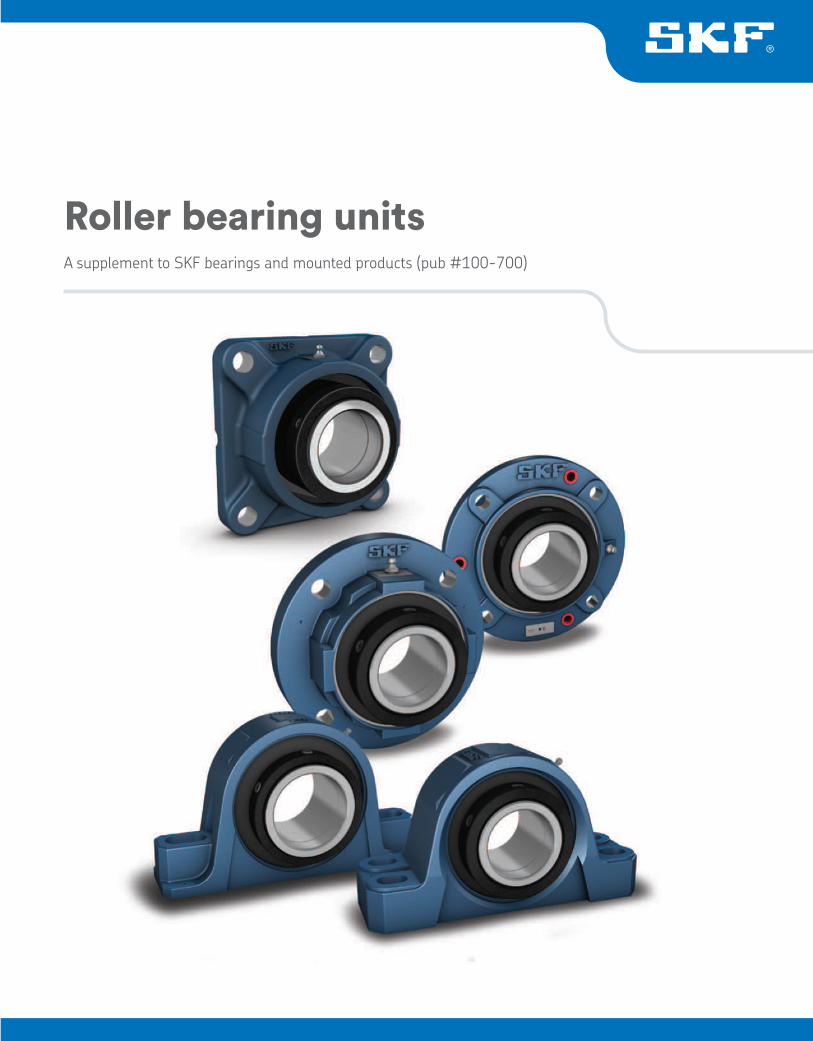
A supplement to SKF bearings and mounted products (pub #100-700)
Roller bearing units
Please note: The page numbers in this supplement reflect the catalog 100-700.
This catalog is intended to be used as a product reference guide only and as such contains only very basic information. This catalog is not intended to be used as a design manual. The data in this catalog is based on current information at the time of press. SKF reserves the right to make changes necessitated by technological developments. Consult SKF USA Inc. prior to design change or order placement.
Additional information on mounting, dismounting, lubrication, and maintenance of SKF products can be found in the SKF Bearing Installation and Maintenance Guide (publication #140-710).
Any reference in this catalog to SKF Applications Engineering is making reference to the SKF USA Inc. Applications Engineering Department that can be reach through the SKF Technical Hotline at 1-888-753-2000.
How to reach SKF USA Inc.
Customer service: 1-888-753-3477
Technical hotline: 1-888-753-2000
Email: [email protected]
Website: www.skfusa.com
Online store: www.ptplace.com
Rolle
r bearin
g u
nits
305
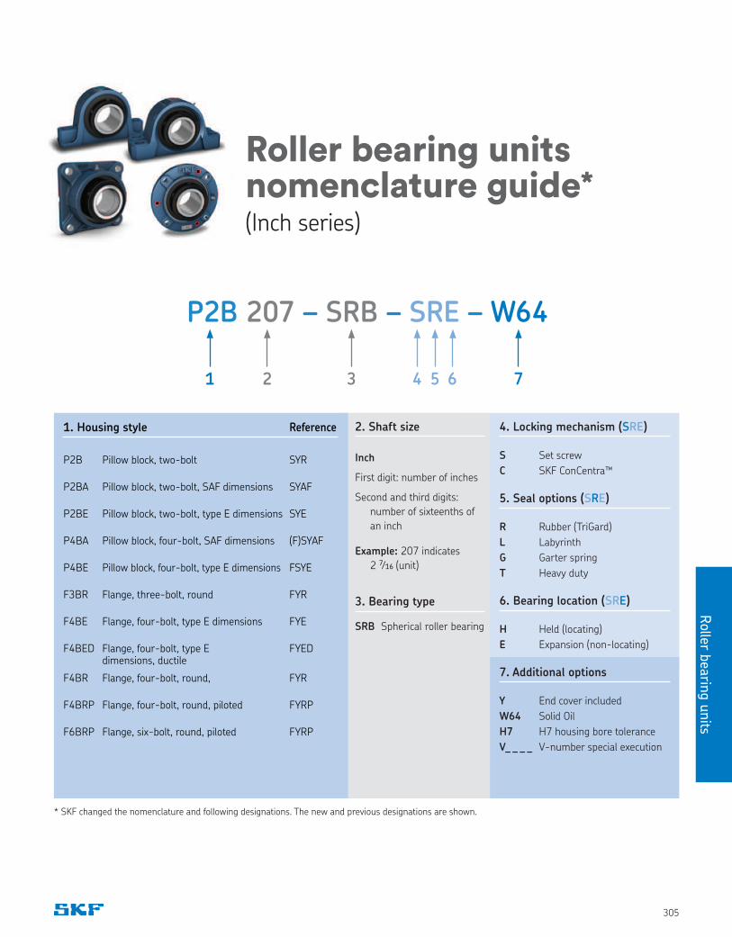
Roller bearing units nomenclature guide*
(Inch series)
4. Locking mechanism (SRE)
S Set screw
C SKF ConCentra™
5. Seal options (SRE)
R Rubber (TriGard)
L Labyrinth
G Garter spring
T Heavy duty
6. Bearing location (SRE)
H Held (locating)
E Expansion (non-locating)
7. Additional options
Y End cover included
W64 Solid Oil
H7 H7 housing bore tolerance
V_ _ _ _ V-number special execution
2. Shaft size
Inch
First digit: number of inches
Second and third digits:
number of sixteenths of
an inch
Example: 207 indicates
2 7⁄16 (unit)
3. Bearing type
SRB Spherical roller bearing
P2B 207 – SRB – SRE – W64
1 2 3 4 5 6 7
1. Housing style Reference
P2B Pillow block, two-bolt SYR
P2BA Pillow block, two-bolt, SAF dimensions SYAF
P2BE Pillow block, two-bolt, type E dimensions SYE
P4BA Pillow block, four-bolt, SAF dimensions (F)SYAF
P4BE Pillow block, four-bolt, type E dimensions FSYE
F3BR Flange, three-bolt, round FYR
F4BE Flange, four-bolt, type E dimensions FYE
F4BED Flange, four-bolt, type E dimensions, ductile
FYED
F4BR Flange, four-bolt, round, FYR
F4BRP Flange, four-bolt, round, piloted FYRP
F6BRP Flange, six-bolt, round, piloted FYRP
* SKF changed the nomenclature and following designations. The new and previous designations are shown.
Roller
beari
ng u
nits
306
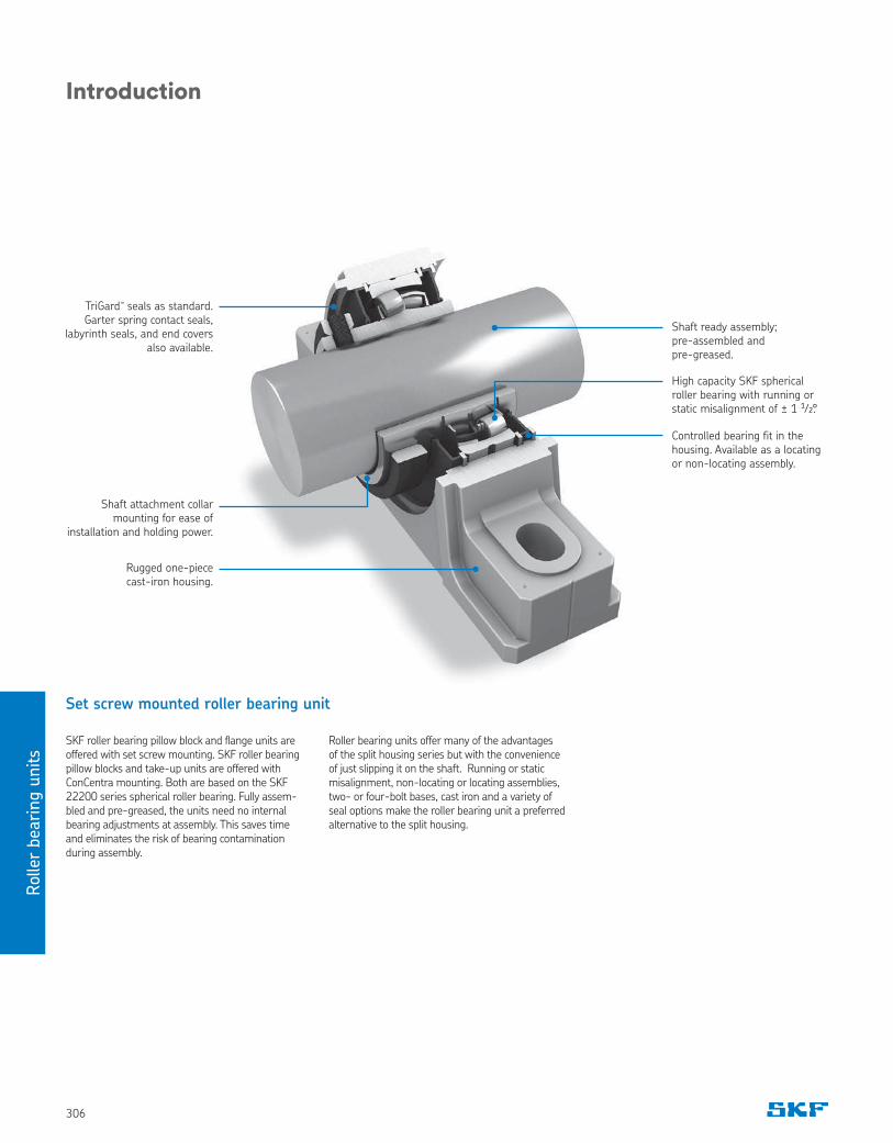
Set screw mounted roller bearing unit
SKF roller bearing pillow block and flange units are offered with set screw mounting. SKF roller bearing pillow blocks and take-up units are offered with ConCentra mounting. Both are based on the SKF 22200 series spherical roller bearing. Fully assem-bled and pre-greased, the units need no internal bearing adjustments at assembly. This saves time and eliminates the risk of bearing contamination during assembly.
TriGard™ seals as standard. Garter spring contact seals,
labyrinth seals, and end covers also available.
Shaft ready assembly; pre-assembled and pre-greased.
High capacity SKF spherical roller bearing with running or static misalignment of ± 1 1⁄2.°
Shaft attachment collar mounting for ease of
installation and holding power.
Rugged one-piece cast-iron housing.
Controlled bearing fit in the housing. Available as a locating or non-locating assembly.
Roller bearing units offer many of the advantages of the split housing series but with the convenience of just slipping it on the shaft. Running or static misalignment, non-locating or locating assemblies, two- or four-bolt bases, cast iron and a variety of seal options make the roller bearing unit a preferred alternative to the split housing.
Introduction
Rolle
r bearin
g u
nits
307
Introduction
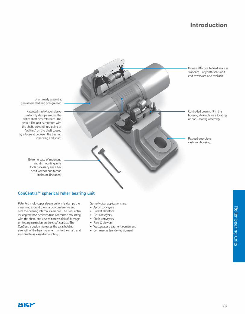
ConCentra™ spherical roller bearing unit
Shaft ready assembly; pre-assembled and pre-greased.
Extreme ease of mounting and dismounting, only
tools necessary are a hex head wrench and torque
indicator. (Included)
Proven effective TriGard seals as standard. Labyrinth seals and end covers are also available.
Patented multi-taper sleeve uniformly clamps around the
entire shaft circumference. The result: The unit is centered with the shaft, preventing slipping or
“walking” on the shaft caused by a loose fit between the bearing
inner ring and shaft. Rugged one-piece cast-iron housing.
Controlled bearing fit in the housing. Available as a locating or non-locating assembly.
Patented multi-taper sleeve uniformly clamps the inner ring around the shaft circumference and sets the bearing internal clearance. The ConCentra locking method achieves true concentric mounting with the shaft, and also minimizes risk of damage or fretting corrosion on the shaft surface. The ConCentra design increases the axial holding strength of the bearing inner ring to the shaft, and also facilitates easy dismounting.
Some typical applications are:• Apron conveyors• Bucket elevators• Belt conveyors• Chain conveyors• Fans & blowers• Wastewater treatment equipment• Commercial laundry equipment
Roller
beari
ng u
nits
308
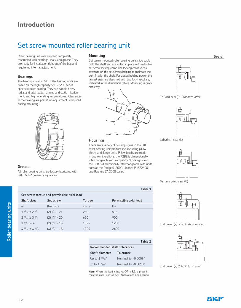
MountingSet screw mounted roller bearing units slide easily onto the shaft and are locked in place with a double set screw locking collar. The locking collar keeps pressure on the set screws helping to maintain the tight fit with the shaft. For added holding power, the largest sizes are designed with two locking collars, indicated in the dimension tables. Mounting is quick and easy.
HousingsThere are a variety of housing styles in the SKF roller bearing unit product line, including pillow blocks and flange units. Pillow blocks are made in two configurations: the P2BE is dimensionally interchangeable with competitor “E” designs and the P2B is dimensionally interchangeable with units such as the Dodge S–2000, Linkbelt P–B22400, and Rexnord ZA 2000 series.
Set screw mounted roller bearing unit
Roller bearing units are supplied completely assembled with bearings, seals, and grease. They are ready for installation right out of the box and require no internal adjustment.
BearingsThe bearings used in SKF roller bearing units are based on the high capacity SKF 22200 series spherical roller bearing. They can handle heavy radial and axial loads, running and static misalign-ment, and high operating temperatures. Clearances in the bearing are preset; no adjustment is required during mounting.
Note: When the load is heavy, C/P < 8.3, a press fit must be used. Consult SKF Applications Engineering.
GreaseAll roller bearing units are factory lubricated with SKF LGEP2 grease or equivalent.
Table 1
Set screw torque and permissible axial load
Shaft sizes Set screw Torque Permissible axial load
in (No.) size in-lbs lbs
1 7/16 to 2 3/16 (2) 3/8” - 24 250 515
2 7/16 to 3 1/2 (2) 1/2” - 20 620 900
3 11/16 to 4 (2) 5/8” - 18 1325 1200
4 7/16 to 4 15/16 (4) 5/8” - 18 1325 2400
Table 2
Recommended shaft tolerances
Shaft diameter Tolerance
Up to 1 15/16" Nominal to -0.0005"
2” to 4 15/16" Nominal to -0.0010"
Introduction
End cover (Y) 1 3/16" to 3" shaft
TriGard seal (R) Standard offer
Labyrinth seal (L)
Garter spring seal (G)
End cover (Y) 3 7/16” shaft and up
Seals
Rolle
r bearin
g u
nits
309
Introduction
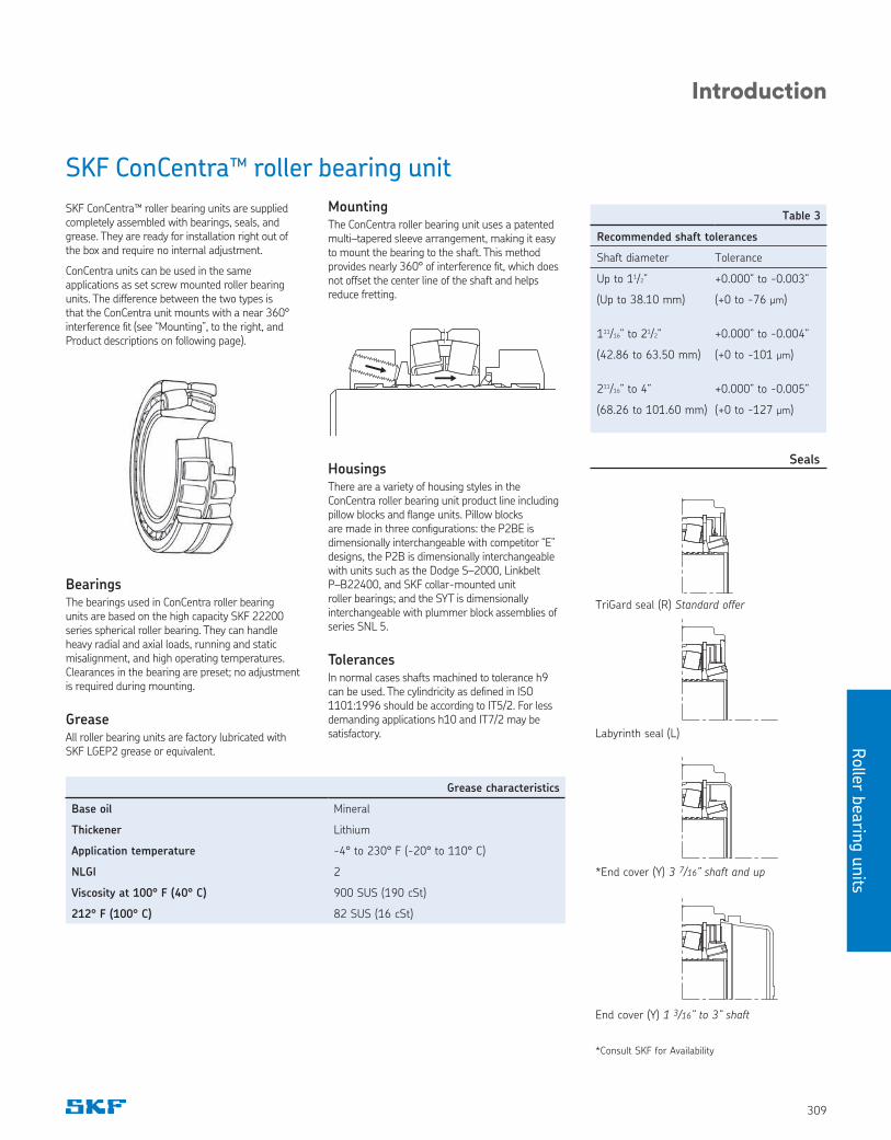
MountingThe ConCentra roller bearing unit uses a patented multi–tapered sleeve arrangement, making it easy to mount the bearing to the shaft. This method provides nearly 360° of interference fit, which does not offset the center line of the shaft and helps reduce fretting.
HousingsThere are a variety of housing styles in the ConCentra roller bearing unit product line including pillow blocks and flange units. Pillow blocks are made in three configurations: the P2BE is dimensionally interchangeable with competitor “E” designs, the P2B is dimensionally interchangeable with units such as the Dodge S–2000, Linkbelt P–B22400, and SKF collar-mounted unit roller bearings; and the SYT is dimensionally interchangeable with plummer block assemblies of series SNL 5.
TolerancesIn normal cases shafts machined to tolerance h9 can be used. The cylindricity as defined in ISO 1101:1996 should be according to IT5/2. For less demanding applications h10 and IT7/2 may be satisfactory.
TriGard seal (R) Standard offer
Labyrinth seal (L)
*End cover (Y) 3 7/16” shaft and up
End cover (Y) 1 3/16” to 3” shaft
*Consult SKF for Availability
SKF ConCentra™ roller bearing unit
SKF ConCentra™ roller bearing units are supplied completely assembled with bearings, seals, and grease. They are ready for installation right out of the box and require no internal adjustment.
ConCentra units can be used in the same applications as set screw mounted roller bearing units. The difference between the two types is that the ConCentra unit mounts with a near 360° interference fit (see “Mounting”, to the right, and Product descriptions on following page).
BearingsThe bearings used in ConCentra roller bearing units are based on the high capacity SKF 22200 series spherical roller bearing. They can handle heavy radial and axial loads, running and static misalignment, and high operating temperatures. Clearances in the bearing are preset; no adjustment is required during mounting.
GreaseAll roller bearing units are factory lubricated with SKF LGEP2 grease or equivalent.
Table 3
Recommended shaft tolerances
Shaft diameter Tolerance
Up to 11/2” +0.000” to -0.003”
(Up to 38.10 mm) (+0 to -76 µm)
111/16” to 21/2” +0.000” to -0.004”
(42.86 to 63.50 mm) (+0 to -101 µm)
211/16” to 4” +0.000” to -0.005”
(68.26 to 101.60 mm) (+0 to -127 µm)
Grease characteristics
Base oil Mineral
Thickener Lithium
Application temperature -4° to 230° F (-20° to 110° C)
NLGI 2
Viscosity at 100° F (40° C) 900 SUS (190 cSt)
212° F (100° C) 82 SUS (16 cSt)
Seals
Roller
beari
ng u
nits
310
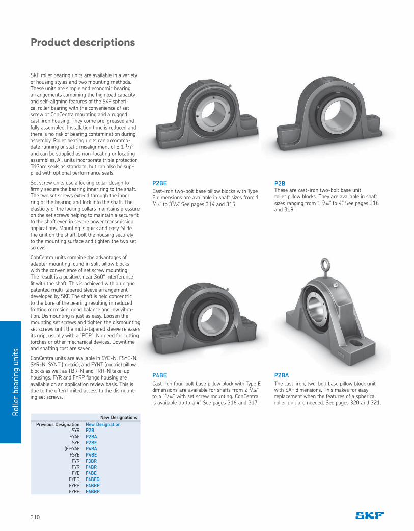
P2BE
Cast-iron two-bolt base pillow blocks with Type E dimensions are available in shaft sizes from 1 7⁄16" to 31⁄2." See pages 314 and 315.
P4BE
Cast iron four-bolt base pillow block with Type E dimensions are available for shafts from 2 7⁄16" to 4 15⁄16" with set screw mounting. ConCentra is available up to a 4." See pages 316 and 317.
P2BThese are cast-iron two-bolt base unit roller pillow blocks. They are available in shaft sizes ranging from 1 7⁄16" to 4." See pages 318 and 319.
Product descriptions
P2BA
The cast-iron, two-bolt base pillow block unit with SAF dimensions. This makes for easy replacement when the features of a spherical roller unit are needed. See pages 320 and 321.
New Designations
Previous Designation New DesignationSYR P2B
SYAF P2BA
SYE P2BE
(F)SYAF P4BA
FSYE P4BE
FYR F3BR
FYR F4BR
FYE F4BE
FYED F4BED
FYRP F4BRP
FYRP F6BRP
SKF roller bearing units are available in a variety of housing styles and two mounting methods. These units are simple and economic bearing arrangements combining the high load capacity and self-aligning features of the SKF spheri-cal roller bearing with the convenience of set screw or ConCentra mounting and a rugged cast-iron housing. They come pre-greased and fully assembled. Installation time is reduced and there is no risk of bearing contamination during assembly. Roller bearing units can accommo-date running or static misalignment of ± 1 1⁄2° and can be supplied as non-locating or locating assemblies. All units incorporate triple protection TriGard seals as standard, but can also be sup-plied with optional performance seals.
Set screw units use a locking collar design to firmly secure the bearing inner ring to the shaft. The two set screws extend through the inner ring of the bearing and lock into the shaft. The elasticity of the locking collars maintains pressure on the set screws helping to maintain a secure fit to the shaft even in severe power transmission applications. Mounting is quick and easy. Slide the unit on the shaft, bolt the housing securely to the mounting surface and tighten the two set screws.
ConCentra units combine the advantages of adapter mounting found in split pillow blocks with the convenience of set screw mounting. The result is a positive, near 360° interference fit with the shaft. This is achieved with a unique patented multi-tapered sleeve arrangement developed by SKF. The shaft is held concentric to the bore of the bearing resulting in reduced fretting corrosion, good balance and low vibra-tion. Dismounting is just as easy. Loosen the mounting set screws and tighten the dismounting set screws until the multi-tapered sleeve releases its grip, usually with a “POP”. No need for cutting torches or other mechanical devices. Downtime and shafting cost are saved.
ConCentra units are available in SYE-N, FSYE-N, SYR-N, SYNT (metric), and FYNT (metric) pillow blocks as well as TBR-N and TRH-N take-up housings. FYR and FYRP flange housing are available on an application review basis. This is due to the often limited access to the dismount-ing set screws.
Rolle
r bearin
g u
nits
311
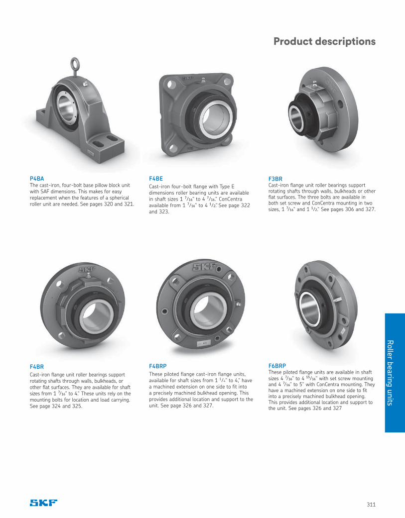
F4BR
Cast-iron flange unit roller bearings support rotating shafts through walls, bulkheads, or other flat surfaces. They are available for shaft sizes from 1 7⁄16" to 4." These units rely on the mounting bolts for location and load carrying. See page 324 and 325.
F4BRP
These piloted flange cast-iron flange units, available for shaft sizes from 1 1⁄4" to 4," have a machined extension on one side to fit into a precisely machined bulkhead opening. This provides additional location and support to the unit. See page 326 and 327.
F4BE
Cast-iron four-bolt flange with Type E dimensions roller bearing units are available in shaft sizes 1 7⁄16" to 4 7⁄16." ConCentra available from 1 7⁄16" to 4 1⁄2." See page 322 and 323.
Product descriptions
P4BAThe cast-iron, four-bolt base pillow block unit with SAF dimensions. This makes for easy replacement when the features of a spherical roller unit are needed. See pages 320 and 321.
F6BRPThese piloted flange units are available in shaft sizes 4 7⁄16" to 4 15⁄16" with set screw mounting and 4 7⁄16" to 5" with ConCentra mounting. They have a machined extension on one side to fit into a precisely machined bulkhead opening. This provides additional location and support to the unit. See pages 326 and 327
F3BRCast-iron flange unit roller bearings support rotating shafts through walls, bulkheads or other flat surfaces. The three bolts are available in both set screw and ConCentra mounting in two sizes, 1 7⁄16" and 1 1⁄2." See pages 306 and 327.
Roller
beari
ng u
nits
312
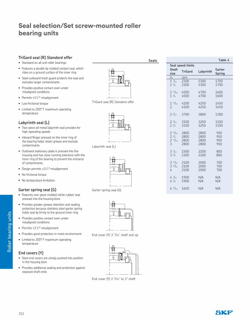
TriGard seal (R) Standard offer• Standard on all unit roller bearings
• Features a double lip molded contact seal, which rides on a ground surface of the inner ring
• Steel outboard trash guard protects the seal and excludes larger contaminants
• Provides positive contact even under misaligned conditions
• Permits ±11/2° misalignment
• Low frictional torque
• Limited to 200° F maximum operating temperature
Labyrinth seal (L)• Two-piece all metal labyrinth seal provides for
high operating speeds
• Inboard flinger pressed on the inner ring of the bearing helps retain grease and exclude contaminants
• Outboard stationary plate is pressed into the housing and has close running tolerance with the inner ring of the bearing to prevent the entrance of contaminants
• Design permits ±11/2° misalignment
• No frictional torque
• No temperature limitation
Garter spring seal (G)• Features one-piece molded nitrile rubber seal
pressed into the housing bore
• Provides greater grease retention and sealing protection because stainless steel garter spring holds seal lip firmly to the ground inner ring
• Provides positive contact even under misaligned conditions
• Permits ±11/2° misalignment
• Provides good protection in moist environment
• Limited to 200° F maximum operating temperature
End covers (Y)• Steel end covers are simply pushed into position
in the housing bore
• Provides additional sealing and protection against exposed shaft ends
Seal selection/Set screw-mounted roller bearing units
Seals
End cover (Y) 1 3/16" to 3" shaft
TriGard seal (R) Standard offer
Labyrinth seal (L)
Garter spring seal (G)
End cover (Y) 3 7/16” shaft and up
Table 4
Seal speed limitsShaft size
TriGard LabyrinthGarter Spring
in rpm1 7/16 2300 5300 17001 1/2 2300 5300 1700
1 11/16 4500 4700 16001 3/4 4500 4700 1600
1 15/16 4100 4250 14502 4100 4250 1450
2 3/16 3700 3800 1300
2 7/16 3100 3250 11002 1/2 3100 3250 1100
2 11/16 2800 2800 9502 3/4 2800 2800 9502 15/16 2800 2800 9503 2800 2800 950
3 7/16 2300 2200 8003 1/2 2300 2200 800
3 11/16 2100 2000 7003 15/16 2100 2000 7004 2100 2000 700
4 7/16 1900 N/A N/A4 1/2 1900 N/A N/A
4 15/16 1650 N/A N/A
Rolle
r bearin
g u
nits
313
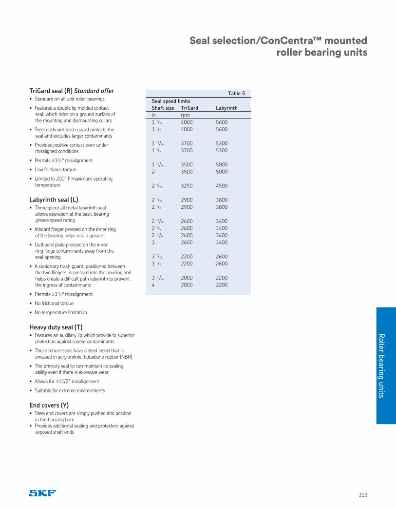
TriGard seal (R) Standard offer• Standard on all unit roller bearings
• Features a double lip molded contact seal, which rides on a ground surface of the mounting and dismounting collars
• Steel outboard trash guard protects the seal and excludes larger contaminants
• Provides positive contact even under misaligned conditions
• Permits ±11/2° misalignment
• Low frictional torque
• Limited to 200° F maximum operating temperature
Labyrinth seal (L)• Three-piece all metal labyrinth seal
allows operation at the basic bearing grease speed rating
• Inboard flinger pressed on the inner ring of the bearing helps retain grease
• Outboard plate pressed on the inner ring flings contaminants away from the seal opening
• A stationary trash guard, positioned between the two flingers, is pressed into the housing and helps create a difficult path labyrinth to prevent the ingress of contaminants
• Permits ±11/2° misalignment
• No frictional torque
• No temperature limitation
Heavy duty seal (T)• Features an auxiliary lip which provide to superior
protection against coarse contaminants
• These robust seals have a steel insert that is encased in acrylonitrile-butadiene rubber (NBR)
• The primary seal lip can maintain its sealing ability even if there is excessive wear
• Allows for ±11/2° misalignment
• Suitable for extreme environments
End covers (Y)• Steel end covers are simply pushed into position
in the housing bore• Provides additional sealing and protection against
exposed shaft ends
Table 5
Seal speed limits
Shaft size TriGard Labyrinth
in rpm
1 7/16 4000 5600
1 1/2 4000 5600
1 11/16 3700 5300
1 3/4 3700 5300
1 15/16 3500 5000
2 3500 5000
2 3/16 3250 4500
2 7/16 2900 3800
2 1/2 2900 3800
2 11/16 2600 3400
2 3/4 2600 3400
2 15/16 2600 3400
3 2600 3400
3 7/16 2200 2600
3 1/2 2200 2600
3 15/16 2000 2200
4 2000 2200
Seal selection/ConCentra™ mounted roller bearing units
Roller
beari
ng u
nits
314
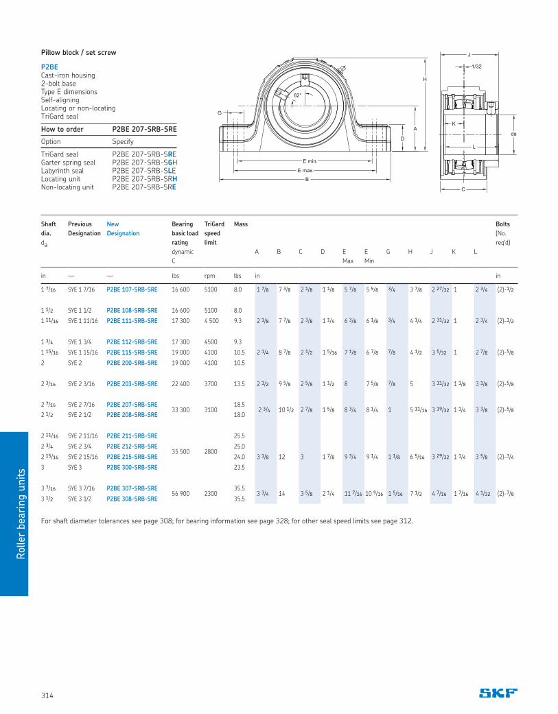
Pillow block / set screw
P2BECast-iron housing2-bolt base Type E dimensionsSelf-aligning Locating or non-locatingTriGard seal
For shaft diameter tolerances see page 308; for bearing information see page 328; for other seal speed limits see page 312.
How to order P2BE 207-SRB-SRE
Option Specify
TriGard seal P2BE 207-SRB-SREGarter spring seal P2BE 207-SRB-SGHLabyrinth seal P2BE 207-SRB-SLELocating unit P2BE 207-SRB-SRHNon-locating unit P2BE 207-SRB-SRE
62°
B
D
A
H
E min.
E max.
G
K
L
C
J
da
1/32
Shaft Previous New Bearing TriGard Mass Bolts
dia. Designation Designation basic load speed (No.
da rating limit req’d)
dynamic A B C D E E G H J K L
C Max Min
in — — lbs rpm lbs in in
1 7/16 SYE 1 7/16 P2BE 107-SRB-SRE 16 600 5100 8.0 1 7/8 7 3/8 2 1/8 1 1/8 5 7/8 5 5/8 3/4 3 7/8 2 27/32 1 2 3/4 (2)-1/2
1 1/2 SYE 1 1/2 P2BE 108-SRB-SRE 16 600 5100 8.0
1 11/16 SYE 1 11/16 P2BE 111-SRB-SRE 17 300 4 500 9.3 2 1/8 7 7/8 2 3/8 1 1/4 6 3/8 6 1/8 3/4 4 1/4 2 31/32 1 2 3/4 (2)-1/2
1 3/4 SYE 1 3/4 P2BE 112-SRB-SRE 17 300 4500 9.3
1 15/16 SYE 1 15/16 P2BE 115-SRB-SRE 19 000 4100 10.5 2 1/4 8 7/8 2 1/2 1 5/16 7 1/8 6 7/8 7/8 4 1/2 3 5/32 1 2 7/8 (2)-5/8
2 SYE 2 P2BE 200-SRB-SRE 19 000 4100 10.5
2 3/16 SYE 2 3/16 P2BE 203-SRB-SRE 22 400 3700 13.5 2 1/2 9 5/8 2 5/8 1 1/2 8 7 5/8 7/8 5 3 11/32 1 1/8 3 1/8 (2)-5/8
2 7/16 SYE 2 7/16 P2BE 207-SRB-SRE33 300 3100
18.5 2 3/4 10 1/2 2 7/8 1 5/8 8 3/4 8 1/4 1 5 11/16 3 19/32 1 1/4 3 3/8 (2)-5/8
2 1/2 SYE 2 1/2 P2BE 208-SRB-SRE 18.0
2 11/16 SYE 2 11/16 P2BE 211-SRB-SRE
35 500 2800
25.5
2 3/4 SYE 2 3/4 P2BE 212-SRB-SRE 25.0
2 15/16 SYE 2 15/16 P2BE 215-SRB-SRE 24.0 3 1/8 12 3 1 7/8 9 3/4 9 1/4 1 1/8 6 5/16 3 29/32 1 1/4 3 5/8 (2)-3/4
3 SYE 3 P2BE 300-SRB-SRE 23.5
3 7/16 SYE 3 7/16 P2BE 307-SRB-SRE56 900 2300
35.53 3/4 14 3 5/8 2 1/4 11 7/16 10 9/16 1 5/16 7 1/2 4 7/16 1 7/16 4 1/32 (2)-7/8
3 1/2 SYE 3 1/2 P2BE 308-SRB-SRE 35.5
Rolle
r bearin
g u
nits
315
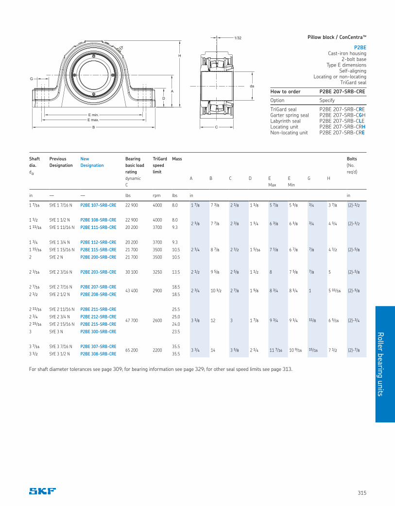
Pillow block / ConCentra™
P2BECast-iron housing
2-bolt baseType E dimensions
Self-aligning Locating or non-locating
TriGard seal
For shaft diameter tolerances see page 309; for bearing information see page 329; for other seal speed limits see page 313.
How to order P2BE 207-SRB-CRE
Option Specify
TriGard seal P2BE 207-SRB-CREGarter spring seal P2BE 207-SRB-CGHLabyrinth seal P2BE 207-SRB-CLELocating unit P2BE 207-SRB-CRHNon-locating unit P2BE 207-SRB-CRE
D
A
H
E min.
E max.
G
B
da
C
1/32
da
Shaft Previous New Bearing TriGard Mass Bolts
dia. Designation Designation basic load speed (No.
da rating limit req’d)
dynamic A B C D E E G H
C Max Min
in — — lbs rpm lbs in in
1 7/16 SYE 1 7/16 N P2BE 107-SRB-CRE 22 900 4000 8.0 1 7/8 7 3/8 2 1/8 1 1/8 5 7/8 5 5/8 3/4 3 7/8 (2)-1/2
1 1/2 SYE 1 1/2 N P2BE 108-SRB-CRE 22 900 4000 8.02 1/8 7 7/8 2 3/8 1 1/4 6 3/8 6 1/8 3/4 4 1/4 (2)-1/2
1 11/16 SYE 1 11/16 N P2BE 111-SRB-CRE 20 200 3700 9.3
1 3/4 SYE 1 3/4 N P2BE 112-SRB-CRE 20 200 3700 9.3
2 1/4 8 7/8 2 1/21 15/16 SYE 1 15/16 N P2BE 115-SRB-CRE 21 700 3500 10.5 1 5/16 7 1/8 6 7/8 7/8 4 1/2 (2)-5/8
2 SYE 2 N P2BE 200-SRB-CRE 21 700 3500 10.5
2 3/16 SYE 2 3/16 N P2BE 203-SRB-CRE 30 100 3250 13.5 2 1/2 9 5/8 2 5/8 1 1/2 8 7 5/8 7/8 5 (2)-5/8
2 7/16 SYE 2 7/16 N P2BE 207-SRB-CRE43 400 2900
18.52 3/4 10 1/2 2 7/8 1 5/8 8 3/4 8 1/4 1 5 11/16 (2)-5/8
2 1/2 SYE 2 1/2 N P2BE 208-SRB-CRE 18.5
2 11/16 SYE 2 11/16 N P2BE 211-SRB-CRE
47 700 2600
25.5
3 1/8 12 3 1 7/8 9 3/4 9 1/4 11/8 6 5/16 (2)-3/42 3/4 SYE 2 3/4 N P2BE 212-SRB-CRE 25.0
2 15/16 SYE 2 15/16 N P2BE 215-SRB-CRE 24.0
3 SYE 3 N P2BE 300-SRB-CRE 23.5
3 7/16 SYE 3 7/16 N P2BE 307-SRB-CRE65 200 2200
35.53 3/4 14 3 5/8 2 1/4 11 7/16 10 9/16 15/16 7 1/2 (2)-7/8
3 1/2 SYE 3 1/2 N P2BE 308-SRB-CRE 35.5
Roller
beari
ng u
nits
316
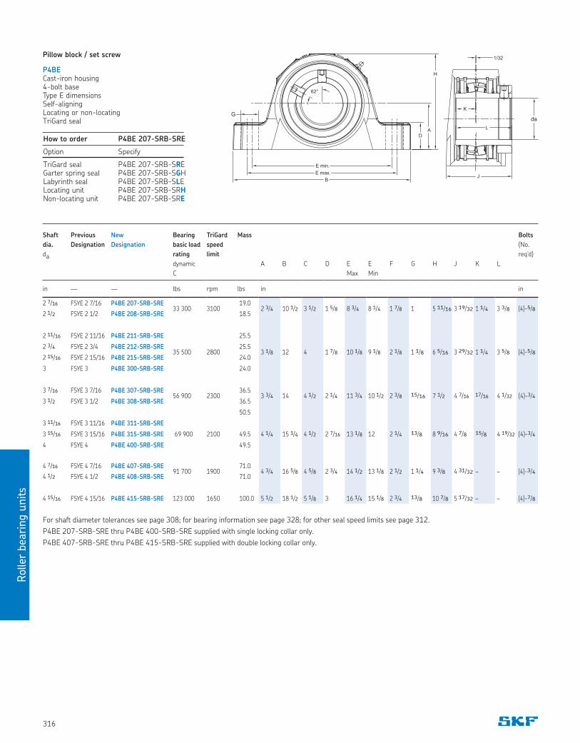
Pillow block / set screw
P4BECast-iron housing4-bolt baseType E dimensionsSelf-aligningLocating or non-locatingTriGard seal
For shaft diameter tolerances see page 308; for bearing information see page 328; for other seal speed limits see page 312.
P4BE 207-SRB-SRE thru P4BE 400-SRB-SRE supplied with single locking collar only.
P4BE 407-SRB-SRE thru P4BE 415-SRB-SRE supplied with double locking collar only.
How to order P4BE 207-SRB-SRE
Option Specify
TriGard seal P4BE 207-SRB-SREGarter spring seal P4BE 207-SRB-SGHLabyrinth seal P4BE 207-SRB-SLELocating unit P4BE 207-SRB-SRHNon-locating unit P4BE 207-SRB-SRE
B
D
A
H
E min.
E max.
da
G
62°
1/32
K
L
J
da
Shaft Previous New Bearing TriGard Mass Bolts
dia. Designation Designation basic load speed (No.
da rating limit req’d)
dynamic A B C D E E F G H J K L
C Max Min
in — — lbs rpm lbs in in
2 7/16 FSYE 2 7/16 P4BE 207-SRB-SRE33 300 3100
19.02 3/4 10 1/2 3 1/2 1 5/8 8 3/4 8 1/4 1 7/8 1 5 11/16 3 19/32 1 1/4 3 3/8 (4)-5/8
2 1/2 FSYE 2 1/2 P4BE 208-SRB-SRE 18.5
2 11/16 FSYE 2 11/16 P4BE 211-SRB-SRE
35 500 2800
25.5
3 1/8 12 4 1 7/8 10 1/8 9 1/8 2 1/8 1 1/8 6 5/16 3 29/32 1 1/4 3 5/8 (4)-5/82 3/4 FSYE 2 3/4 P4BE 212-SRB-SRE 25.5
2 15/16 FSYE 2 15/16 P4BE 215-SRB-SRE 24.0
3 FSYE 3 P4BE 300-SRB-SRE 24.0
3 7/16 FSYE 3 7/16 P4BE 307-SRB-SRE56 900 2300
36.53 3/4 14 4 1/2 2 1/4 11 3/4 10 1/2 2 3/8 15/16 7 1/2 4 7/16 17/16 4 1/32 (4)-3/4
3 1/2 FSYE 3 1/2 P4BE 308-SRB-SRE 36.5
50.5
3 11/16 FSYE 3 11/16 P4BE 311-SRB-SRE
3 15/16 FSYE 3 15/16 P4BE 315-SRB-SRE 69 900 2100 49.5 4 1/4 15 1/4 4 1/2 2 7/16 13 1/8 12 2 1/4 13/8 8 9/16 4 7/8 15/8 4 19/32 (4)-3/4
4 FSYE 4 P4BE 400-SRB-SRE 49.5
4 7/16 FSYE 4 7/16 P4BE 407-SRB-SRE91 700 1900
71.04 3/4 16 5/8 4 5/8 2 3/4 14 1/2 13 1/8 2 1/2 1 1/4 9 3/8 4 31/32 – – (4)-3/4
4 1/2 FSYE 4 1/2 P4BE 408-SRB-SRE 71.0
4 15/16 FSYE 4 15/16 P4BE 415-SRB-SRE 123 000 1650 100.0 5 1/2 18 1/2 5 1/8 3 16 1/4 15 1/8 2 3/4 13/8 10 7/8 5 17/32 – – (4)-7/8
Rolle
r bearin
g u
nits
317
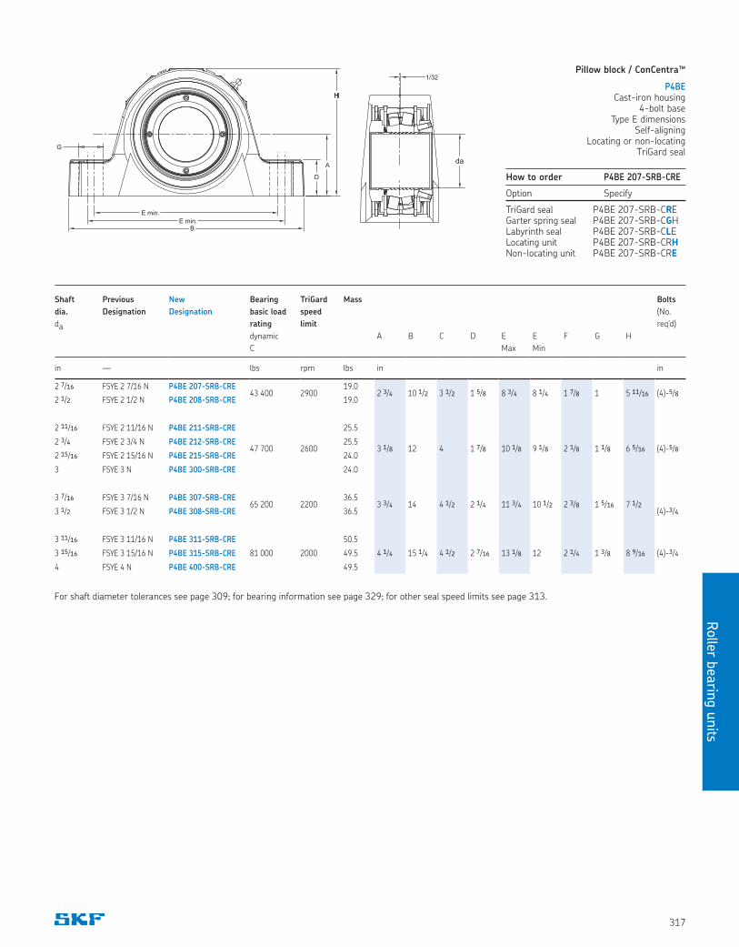
Pillow block / ConCentra™
P4BECast-iron housing
4-bolt baseType E dimensions
Self-aligningLocating or non-locating
TriGard seal
How to order P4BE 207-SRB-CRE
Option Specify
TriGard seal P4BE 207-SRB-CREGarter spring seal P4BE 207-SRB-CGHLabyrinth seal P4BE 207-SRB-CLELocating unit P4BE 207-SRB-CRHNon-locating unit P4BE 207-SRB-CRE
Shaft Previous New Bearing TriGard Mass Bolts
dia. Designation Designation basic load speed (No.
da rating limit req’d)
dynamic A B C D E E F G H
C Max Min
in — lbs rpm lbs in in
2 7/16 FSYE 2 7/16 N P4BE 207-SRB-CRE43 400 2900
19.02 3/4 10 1/2 3 1/2 1 5/8 8 3/4 8 1/4 1 7/8 1 5 11/16 (4)-5/8
2 1/2 FSYE 2 1/2 N P4BE 208-SRB-CRE 19.0
2 11/16 FSYE 2 11/16 N P4BE 211-SRB-CRE
47 700 2600
25.5
3 1/8 12 4 1 7/8 10 1/8 9 1/8 2 1/8 1 1/8 6 5/16 (4)-5/82 3/4 FSYE 2 3/4 N P4BE 212-SRB-CRE 25.5
2 15/16 FSYE 2 15/16 N P4BE 215-SRB-CRE 24.0
3 FSYE 3 N P4BE 300-SRB-CRE 24.0
3 7/16 FSYE 3 7/16 N P4BE 307-SRB-CRE65 200 2200
36.53 3/4 14 4 1/2 2 1/4 11 3/4 10 1/2 2 3/8 1 5/16 7 1/2
3 1/2 FSYE 3 1/2 N P4BE 308-SRB-CRE 36.5 (4)-3/4
3 11/16 FSYE 3 11/16 N P4BE 311-SRB-CRE 50.5
3 15/16 FSYE 3 15/16 N P4BE 315-SRB-CRE 81 000 2000 49.5 4 1/4 15 1/4 4 1/2 2 7/16 13 1/8 12 2 1/4 1 3/8 8 9/16 (4)-3/4
4 FSYE 4 N P4BE 400-SRB-CRE 49.5
For shaft diameter tolerances see page 309; for bearing information see page 329; for other seal speed limits see page 313.
B
D
A
H
E min.
E min.
daG
1/32
daG
Roller
beari
ng u
nits
318
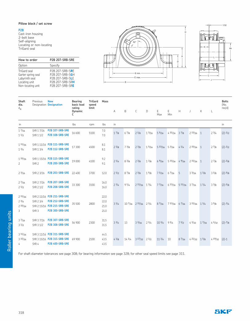
Pillow block / set screw
P2BCast-iron housing2-bolt baseSelf-aligningLocating or non-locatingTriGard seal
For shaft diameter tolerances see page 308; for bearing information see page 328; for other seal speed limits see page 311.
How to order P2B 207-SRB-SRE
Option Specify
TriGard seal P2B 207-SRB-SREGarter spring seal P2B 207-SRB-SGHLabyrinth seal P2B 207-SRB-SLELocating unit P2B 207-SRB-SRHNon-locating unit P2B 207-SRB-SRE
Shaft dia. da
Previous Designation
New Designation
Bearing basic load rating Dynamic C
TriGard speed limit
Mass A
B
C
D
E Max
E Min
H
J
K
L
Bolts (No. req’d)
in lbs rpm lbs in in
1 7/16 SYR 1 7/16 P2B 107-SRB-SRE16 600 5100
7.01 7/8 6 7/8 2 1/8 1 3/16 5 5/16 4 11/16 3 7/8 2 13/16 1 2 3/4 (2)-1/2
1 1/2 SYR 1 1/2 P2B 108-SRB-SRE 7.0
1 11/16 SYR 1 11/16 P2B 111-SRB-SRE17 300 4500
8.12 1/8 7 3/8 2 3/8 1 5/16 5 13/16 5 3/16 4 1/4 2 15/16 1 2 7/8 (2)-1/2
1 3/4 SYR 1 3/4 P2B 112-SRB-SRE 8.1
1 15/16 SYR 1 15/16 P2B 115-SRB-SRE19 000 4100
9.22 1/4 8 3/8 2 3/8 1 3/8 6 9/16 5 15/16 4 9/16 2 15/16 1 2 7/8 (2)-5/8
2 SYR 2 P2B 200-SRB-SRE 9.1
2 3/16 SYR 2 3/16 P2B 203-SRB-SRE 22 400 3700 12.0 2 1/2 8 7/8 2 3/8 1 5/8 7 1/16 6 7/16 5 3 3/16 1 1/8 3 1/8 (2)-5/8
2 7/16 SYR 2 7/16 P2B 207-SRB-SRE33 300 3100
16.02 3/4 9 1/4 2 11/16 1 3/4 7 7/16 6 13/16 5 11/16 3 7/16 1 1/4 3 3/8 (2)-5/8
2 1/2 SYR 2 1/2 P2B 208-SRB-SRE 16.0
2 11/16 SYR 2 11/16 P2B 211-SRB-SRE
35 500 2800
22.0
3 1/4 10 7/16 2 11/16 2 1/4 8 7/16 7 13/16 6 7/16 3 11/16 1 1/4 3 5/8 (2)-3/42 3/4 SYR 2 3/4 P2B 212-SRB-SRE 22.0
2 15/16 SYR 2 15/16 P2B 215-SRB-SRE 21.0
3 SYR 3 P2B 300-SRB-SRE 21.0
3 7/16 SYR 3 7/16 P2B 307-SRB-SRE56 900 2300
31.53 3/4 13 3 3/16 2 1/4 10 3/4 9 1/4 7 1/2 4 3/32 1 7/16 4 1/32 (2)-7/8
3 1/2 SYR 3 1/2 P2B 308-SRB-SRE 31.5
3 11/16 SYR 3 11/16 P2B 311-SRB-SRE
69 900 2100
44.5
4 1/8 14 1/4 3 17/32 2 1/2 11 3/4 10 8 7/16 4 21/32 1 5/8 4 19/32 (2)-13 15/16 SYR 3 15/16 P2B 315-SRB-SRE 43.5
4 SYR 4 P2B 400-SRB-SRE 43.5
B
H
A
D
62°
E max.
E min.
1/32
K
L
C
J
da
Rolle
r bearin
g u
nits
319
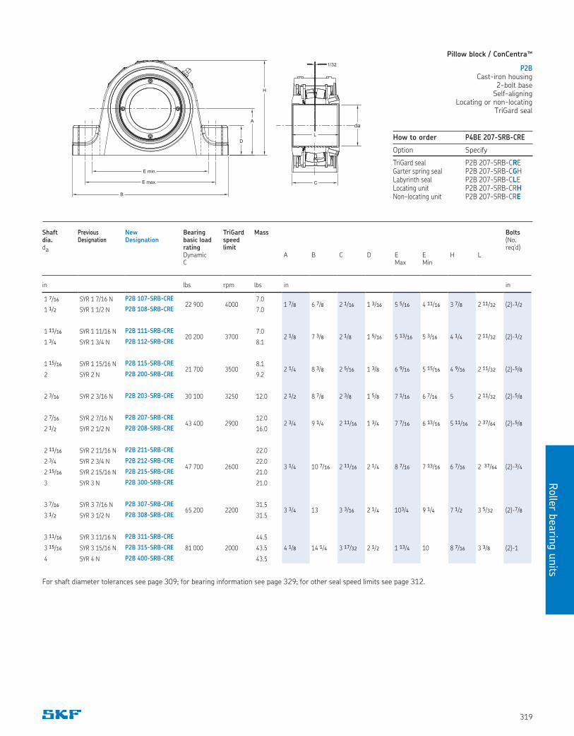
Pillow block / ConCentra™
P2BCast-iron housing
2-bolt baseSelf-aligning
Locating or non-locatingTriGard seal
How to order P4BE 207-SRB-CRE
Option Specify
TriGard seal P2B 207-SRB-CREGarter spring seal P2B 207-SRB-CGHLabyrinth seal P2B 207-SRB-CLELocating unit P2B 207-SRB-CRHNon-locating unit P2B 207-SRB-CRE
For shaft diameter tolerances see page 309; for bearing information see page 329; for other seal speed limits see page 312.
Shaft dia. da
Previous Designation
NewDesignation
Bearing basic load rating Dynamic C
TriGard speed limit
Mass A
B
C
D
E Max
E Min
H
L
Bolts (No. req’d)
in lbs rpm lbs in in
1 7/16 SYR 1 7/16 N P2B 107-SRB-CRE22 900 4000
7.01 7/8 6 7/8 2 1/16 1 3/16 5 5/16 4 11/16 3 7/8 2 11/32 (2)-1/2
1 1/2 SYR 1 1/2 N P2B 108-SRB-CRE 7.0
1 11/16 SYR 1 11/16 N P2B 111-SRB-CRE20 200 3700
7.02 1/8 7 3/8 2 1/8 1 5/16 5 13/16 5 3/16 4 1/4 2 11/32 (2)-1/2
1 3/4 SYR 1 3/4 N P2B 112-SRB-CRE 8.1
1 15/16 SYR 1 15/16 N P2B 115-SRB-CRE21 700 3500
8.12 1/4 8 3/8 2 5/16 1 3/8 6 9/16 5 15/16 4 9/16 2 11/32 (2)-5/8
2 SYR 2 N P2B 200-SRB-CRE 9.2
2 3/16 SYR 2 3/16 N P2B 203-SRB-CRE 30 100 3250 12.0 2 1/2 8 7/8 2 3/8 1 5/8 7 1/16 6 7/16 5 2 11/32 (2)-5/8
2 7/16 SYR 2 7/16 N P2B 207-SRB-CRE43 400 2900
12.02 3/4 9 1/4 2 11/16 1 3/4 7 7/16 6 13/16 5 11/16 2 37/64 (2)-5/8
2 1/2 SYR 2 1/2 N P2B 208-SRB-CRE 16.0
2 11/16 SYR 2 11/16 N P2B 211-SRB-CRE
47 700 2600
22.0
3 1/4 10 7/16 2 11/16 2 1/4 8 7/16 7 13/16 6 7/16 2 37/64 (2)-3/42 3/4 SYR 2 3/4 N P2B 212-SRB-CRE 22.0
2 15/16 SYR 2 15/16 N P2B 215-SRB-CRE 21.0
3 SYR 3 N P2B 300-SRB-CRE 21.0
3 7/16 SYR 3 7/16 N P2B 307-SRB-CRE65 200 2200
31.53 3/4 13 3 3/16 2 1/4 103/4 9 1/4 7 1/2 3 5/32 (2)-7/8
3 1/2 SYR 3 1/2 N P2B 308-SRB-CRE 31.5
3 11/16 SYR 3 11/16 N P2B 311-SRB-CRE 44.5
3 15/16 SYR 3 15/16 N P2B 315-SRB-CRE 81 000 2000 43.5 4 1/8 14 1/4 3 17/32 2 1/2 1 13/4 10 8 7/16 3 3/8 (2)-1
4 SYR 4 N P2B 400-SRB-CRE 43.5
B
H
A
D
E max.
E min.
C
1/32
da
L
Roller
beari
ng u
nits
320
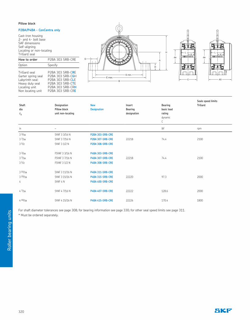
How to order P2BA 303 SRB-CRE
Option Specify
TriGard seal P2BA 303 SRB-CREGarter spring seal P2BA 303 SRB-CGH Labyrinth seal: P2BA 303 SRB-CLEHeavy duty seal P2BA 303 SRB-CTELocating unit P2BA 303 SRB-CRHNon locating unit P2BA 303 SRB-CRE
Seals speed limits
Shaft
dia
da
Designation
Pillow block
unit non-locating
New
Designation
Insert
Bearing
designation
Bearing
basic load
rating
dynamic
C
TriGard
in – lbf rpm
3 3/16 SYAF 3 3/16 N P2BA 303-SRB-CRE
3 7/16 SYAF 3 7/16 N P2BA 307-SRB-CRE 22218 74.4 2100
3 1/2 SYAF 3 1/2 N P2BA 308-SRB-CRE
3 3/16 FSYAF 3 3/16 N P4BA 303-SRB-CRE
3 7/16 FSYAF 3 7/16 N P4BA 307-SRB-CRE 22218 74.4 2100
3 1/2 FSYAF 3 1/2 N P4BA 308-SRB-CRE
3 11/16 SYAF 3 11/16 N P4BA 311-SRB-CRE
3 15/16 SYAF 3 15/16 N P4BA 315-SRB-CRE 22220 97.3 2000
4 SYAF 4 N P4BA 400-SRB-CRE
4 7/16 SYAF 4 7/16 N P4BA 407-SRB-CRE 22222 128.6 2000
4 15/16 SYAF 4 15/16 N P4BA 415-SRB-CRE 22226 170.4 1800
Pillow block
P2BA/P4BA - ConCentra only
Cast-iron housing2- and 4- bolt baseSAF dimensionsSelf-aligningLocating or non-locatingTriGard seal
For shaft diameter tolerances see page 308; for bearing information see page 330; for other seal speed limits see page 311.
* Must be ordered separately.
D
A
H
E min.
E max.
G
B
da
A5
LK
da
C
LK
Rolle
r bearin
g u
nits
321
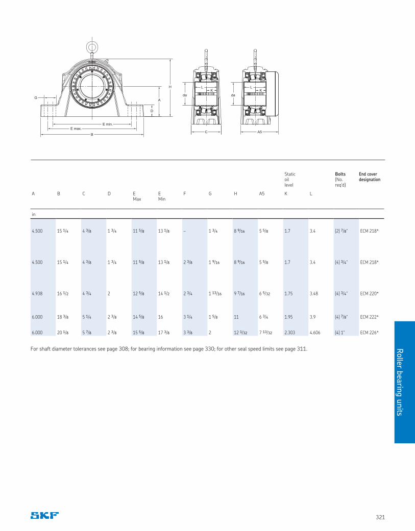
Static oil level
Bolts (No. req’d)
End cover designation
A B C D E Max
E Min
F G H A5 K L
in
4.500 15 1/4 4 3/8 1 3/4 11 5/8 13 1/8 – 1 3/4 8 9/16 5 5/8 1.7 3.4 (2) 7/8" ECM 218*
4.500 15 1/4 4 3/8 1 3/4 11 5/8 13 1/8 2 3/8 1 9/16 8 9/16 5 5/8 1.7 3.4 (4) 3/4" ECM 218*
4.938 16 1/2 4 3/4 2 12 5/8 14 1/2 2 3/4 1 13/16 9 7/16 6 5/32 1.75 3.48 (4) 3/4" ECM 220*
6.000 18 3/8 5 1/4 2 3/8 14 5/8 16 3 1/4 1 5/8 11 6 3/4 1.95 3.9 (4) 7/8" ECM 222*
6.000 20 1/8 5 7/8 2 3/8 15 5/8 17 3/8 3 3/8 2 12 1/32 7 13/32 2.303 4.606 (4) 1" ECM 226*
For shaft diameter tolerances see page 308; for bearing information see page 330; for other seal speed limits see page 311.
D
A
H
E min.
E max.
G
B
da
A5
LK
da
C
LK
Roller
beari
ng u
nits
322
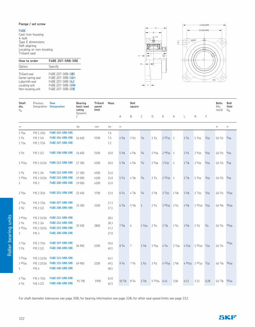
How to order F4BE 207-SRB-SRE
Option Specify
TriGard seal F4BE 207-SRB-SREGarter spring seal F4BE 207-SRB-SGHLabyrinth seal F4BE 207-SRB-SLELocating unit F4BE 207-SRB-SRHNon-locating unit F4BE 207-SRB-SRE
Flange / set screw
F4BECast-iron housing4-boltType E dimensionsSelf-aligningLocating or non-locatingTriGard seal
5XX
K
1/32
Db
C
L
D
E
R
Y
A SQUARE
B SQUARE
Shaft dia. da
Previous Designation
New Designation
Bearing basic load rating Dynamic C
TriGard speed limit
Mass A
Bolt square B
C
D
E
K
L
R
Y
Bolts (No. req’d)
Bolt Hole Db
in lbs rpm lbs in in in
1 3/16 FYE 1 3/16 F4BE 103-SRB-SRE
16 600
7.6
4 5/8 3 1/2 3/4 2 1/4 2 27/32 1 2 3/4 1 3/32 3/32 (4)-1/2 9/161 1/4 FYE 1 1/4 F4BE 104-SRB-SRE 5100 7.5
1 7/16 FYE 1 7/16 F4BE 107-SRB-SRE 7.2
1 1/2 FYE 1 1/2 F4BE 108-SRB-SRE 16 600 5100 10.0 5 3/8 4 1/8 3/4 2 5/16 2 29/32 1 2 3/4 1 5/32 5/32 (4)-1/2 9/16
1 11/16 FYE 1 11/16 F4BE 111-SRB-SRE 17 300 4500 10.0 5 3/8 4 1/8 3/4 2 5/16 3 1/32 1 2 7/8 1 5/32 5/32 (4)-1/2 9/16
1 3/4 FYE 1 3/4 F4BE 112-SRB-SRE 17 300 4500 11.0
5 1/2 4 3/8 3/4 2 1/4 2 31/32 1 2 7/8 1 3/32 3/32 (4)-1/2 9/161 15/16 FYE 1 15/16 F4BE 115-SRB-SRE 19 000 4100 11.0
2 FYE 2 F4BE 200-SRB-SRE 19 000 4100 11.0
2 3/16 FYE 2 3/16 F4BE 203-SRB-SRE 22 400 3700 13.5 6 1/4 4 7/8 3/4 2 3/8 3 7/32 1 1/8 3 1/8 1 7/32 3/32 (4)-1/2 11/16
2 7/16 FYE 2 7/16 F4BE 207-SRB-SRE33 300 3100
17.36 7/8 5 3/8 1 2 3/4 3 15/32 1 1/4 3 3/8 1 11/32 3/32 (4)-5/8 11/16
2 1/2 FYE 2 1/2 F4BE 208-SRB-SRE 17.1
2 11/16 FYE 2 11/16 F4BE 211-SRB-SRE
35 500 2800
28.5
7 5/8 6 1 1/16 2 3/4 3 7/8 1 1/4 3 5/8 1 1/2 1/4 (4)-3/4 13/162 3/4 FYE 2 3/4 F4BE 212-SRB-SRE 28.3
2 15/16 FYE 2 15/16 F4BE 215-SRB-SRE 27.2
3 FYE 3 F4BE 300-SRB-SRE 27.0
3 7/16 FYE 3 7/16 F4BE 307-SRB-SRE56 900 2300
40.68 3/4 7 1 1/8 3 5/16 4 1/4 1 7/16 4 1/32 1 21/32 7/32 (4)-3/4
13/16
3 1/2 FYE 3 1/2 F4BE 308-SRB-SRE 40.1
3 11/16 FYE 3 11/16 F4BE 311-SRB-SRE
69 900 2100
64.1
9 3/4 7 3/4 1 1/4 3 1/2 4 13/16 1 5/8 4 19/32 1 27/32 7/32 (4)-7/8 15/163 15/16 FYE 3 15/16 F4BE 315-SRB-SRE 69.1
4 FYE 4 F4BE 400-SRB-SRE 68.1
4 7/16 FYE 4 7/16 F4BE 407-SRB-SRE 91 700 1900
63.010 7/8 8 3/4 2 3/8 5 13/16 6.41 3.06 6.13 3.33 0.28 (4)-7/8 15/16
4 1/2 F4E 4 1/2 F4BE 408-SRB-SRE 62.5
For shaft diameter tolerances see page 308; for bearing information see page 328; for other seal speed limits see page 312.
Rolle
r bearin
g u
nits
323
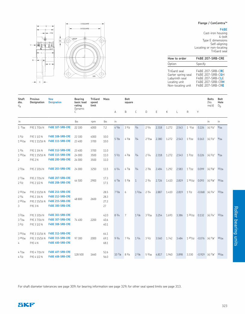
How to order F4BE 207-SRB-CRE
Option Specify
TriGard seal F4BE 207-SRB-CREGarter spring seal F4BE 207-SRB-CGHLabyrinth seal F4BE 207-SRB-CLELocating unit F4BE 207-SRB-CRHNon-locating unit F4BE 207-SRB-CRE
Flange / ConCentra™
F4BECast-iron housing
4-boltType E dimensions
Self-aligningLocating or non-locating
TriGard seal
5XX
C
A SQUARE
B SQUARE
Db
1/32
D
E
L
R
Y
K
Shaft dia. da
Previous Designation
New Designation
Bearing basic load rating Dynamic C
TriGard speed limit
Mass A
Bolt square B
C
D
E
K
L
R
Y
Bolts (No. req’d)
Bolt Hole Db
in lbs rpm lbs in in in
1 7/16 FYE 1 7/16 N F4BE 107-SRB-CRE 22 100 4000 7.2 4 5/8 3 1/2 3/4 2 1/4 2.318 1.272 2.543 1 3/32 0.226 (4) 1/2" 9/16
1 1/2 FYE 1 1/2 N F4BE 108-SRB-CRE 22 100 4000 10.05 3/8 4 1/8 3/4 2 5/16 2.380 1.272 2.543 1 5/32 0.163 (4) 1/2" 9/16
1 11/16 FYE 1 11/16 N F4BE 111-SRB-CRE 23 400 3700 10.0
1 3/4 FYE 1 3/4 N F4BE 112-SRB-CRE 23 400 3700 11.0
5 1/2 4 3/8 3/4 2 1/4 2.318 1.272 2.543 1 3/32 0.226 (4) 1/2" 9/161 15/16 FYE 1 15/16 N F4BE 115-SRB-CRE 24 000 3500 11.0
2 FYE 2 N F4BE 200-SRB-CRE 24 000 3500 11.0
2 3/16 FYE 2 3/16 N F4BE 203-SRB-CRE 24 000 3250 13.5 6 1/4 4 7/8 3/4 2 3/8 2.484 1.292 2.583 1 7/32 0.099 (4) 5/8" 11/16
2 7/16 FYE 2 7/16 N F4BE 207-SRB-CRE44 500 2900
17.36 7/8 5 3/8 1 2 3/4 2.726 1.410 2.819 1 11/32 0.093 (4) 5/8" 11/16
2 1/2 FYE 2 1/2 N F4BE 208-SRB-CRE 17.1
2 11/16 FYE 2 11/16 N F4BE 211-SRB-CRE
48 800 2600
28.5 7 5/8 6 1 1/16 2 3/4 2.887 1.410 2.819 1 1/2 -0.068 (4) 3/4" 13/16
2 3/4 FYE 2 3/4 N F4BE 212-SRB-CRE 28.3
2 15/16 FYE 2 15/16 N F4BE 215-SRB-CRE 27.2
3 FYE 3 N F4BE 300-SRB-CRE 27
3 3/16 FYE 3 3/16 N F4BE 303-SRB-CRE
74 400 2200
42.0 8 3/4 7 1 1/8 3 5/16 3.254 1.693 3.386 1 21/32 0.132 (4) 3/4" 13/16
3 7/16 FYE 3 7/16 N F4BE 307-SRB-CRE 40.6
3 1/2 FYE 3 1/2 N F4BE 308-SRB-CRE 40.1
3 11/16 FYE 3 11/16 N F4BE 311-SRB-CRE
97 300 2000
64.1
9 3/4 7 3/4 1 1/4 3 1/2 3.560 1.742 3.484 1 27/32 -0.076 (4) 7/8" 15/163 15/16 FYE 3 15/16 N F4BE 315-SRB-CRE 69.1
4 FYE 4 N F4BE 400-SRB-CRE 68.1
4 7/16 FYE 4 7/16 N F4BE 407-SRB-CRE128 500 1660
52.610 7/8 8 3/4 2 3/8 5 3/16 4.817 1.940 3.898 3.330 -0.919 (4) 7/8" 15/16
4 1/2 FYE 4 1/2 N F4BE 408-SRB-CRE 56.0
For shaft diameter tolerances see page 309; for bearing information see page 329; for other seal speed limits see page 313.
Roller
beari
ng u
nits
324
Shaft
dia.
da
Previous
Designation
New
Designation
Bearing
basic load
rating
Dynamic
C
TriGard
speed
limit
Mass
A
Bolt
square
B
C
D
E
H
J
K
L
R
Y
Bolts
(No.
req’d)
Bolt
Hole
Db
in lbs rpm lbs in in in
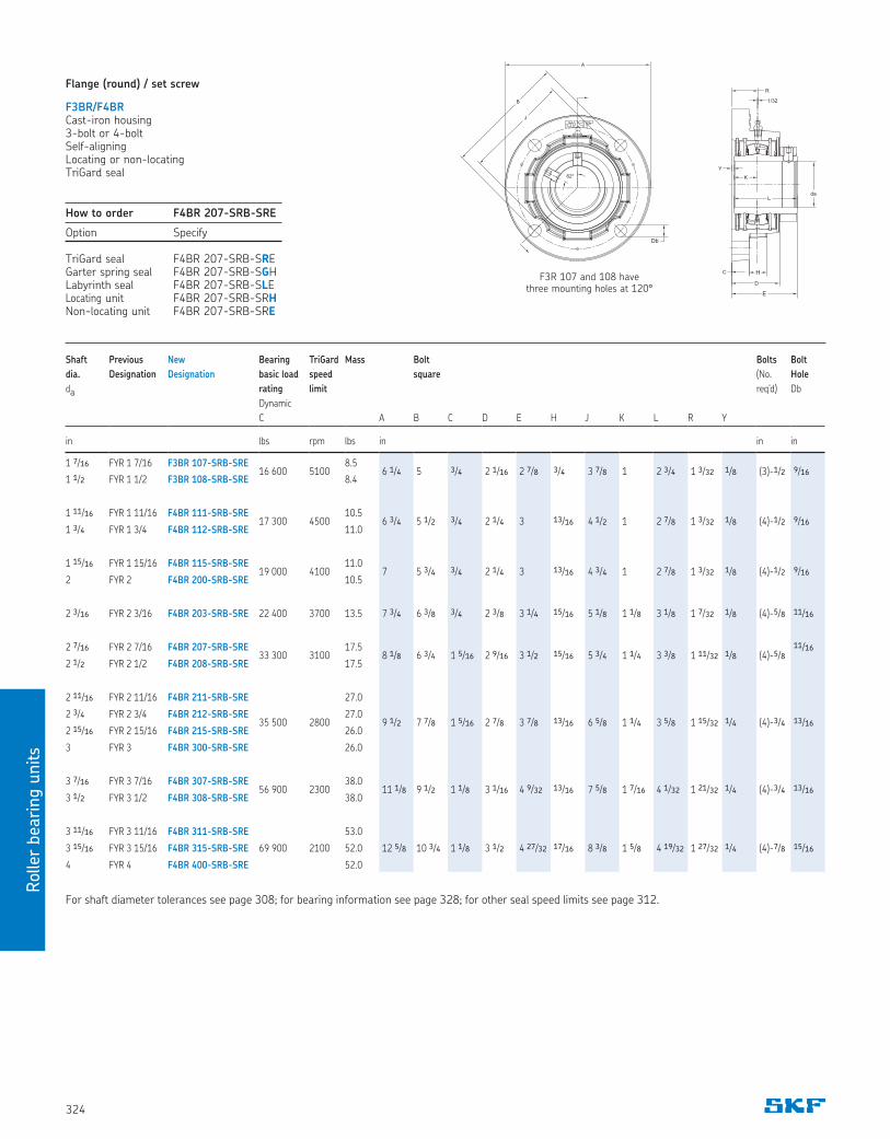
1 7/16 FYR 1 7/16 F3BR 107-SRB-SRE16 600 5100
8.56 1/4 5 3/4 2 1/16 2 7/8 3/4 3 7/8 1 2 3/4 1 3/32 1/8 (3)-1/2 9/16
1 1/2 FYR 1 1/2 F3BR 108-SRB-SRE 8.4
1 11/16 FYR 1 11/16 F4BR 111-SRB-SRE17 300 4500
10.56 3/4 5 1/2 3/4 2 1/4 3 13/16 4 1/2 1 2 7/8 1 3/32 1/8 (4)-1/2 9/16
1 3/4 FYR 1 3/4 F4BR 112-SRB-SRE 11.0
1 15/16 FYR 1 15/16 F4BR 115-SRB-SRE19 000 4100
11.07 5 3/4 3/4 2 1/4 3 13/16 4 3/4 1 2 7/8 1 3/32 1/8 (4)-1/2 9/16
2 FYR 2 F4BR 200-SRB-SRE 10.5
2 3/16 FYR 2 3/16 F4BR 203-SRB-SRE 22 400 3700 13.5 7 3/4 6 3/8 3/4 2 3/8 3 1/4 15/16 5 1/8 1 1/8 3 1/8 1 7/32 1/8 (4)-5/8 11/16
2 7/16 FYR 2 7/16 F4BR 207-SRB-SRE33 300 3100
17.58 1/8 6 3/4 1 5/16 2 9/16 3 1/2 15/16 5 3/4 1 1/4 3 3/8 1 11/32 1/8 (4)-5/8
11/16
2 1/2 FYR 2 1/2 F4BR 208-SRB-SRE 17.5
2 11/16 FYR 2 11/16 F4BR 211-SRB-SRE
35 500 2800
27.0
9 1/2 7 7/8 1 5/16 2 7/8 3 7/8 13/16 6 5/8 1 1/4 3 5/8 1 15/32 1/4 (4)-3/4 13/162 3/4 FYR 2 3/4 F4BR 212-SRB-SRE 27.0
2 15/16 FYR 2 15/16 F4BR 215-SRB-SRE 26.0
3 FYR 3 F4BR 300-SRB-SRE 26.0
3 7/16 FYR 3 7/16 F4BR 307-SRB-SRE56 900 2300
38.011 1/8 9 1/2 1 1/8 3 1/16 4 9/32 13/16 7 5/8 1 7/16 4 1/32 1 21/32 1/4 (4)-3/4 13/16
3 1/2 FYR 3 1/2 F4BR 308-SRB-SRE 38.0
3 11/16 FYR 3 11/16 F4BR 311-SRB-SRE
69 900 2100
53.0
12 5/8 10 3/4 1 1/8 3 1/2 4 27/32 17/16 8 3/8 1 5/8 4 19/32 1 27/32 1/4 (4)-7/8 15/163 15/16 FYR 3 15/16 F4BR 315-SRB-SRE 52.0
4 FYR 4 F4BR 400-SRB-SRE 52.0
B
A
62°
Db
J
R
da
1/32
Y
L
C
D
K
E
H
Flange (round) / set screw
F3BR/F4BRCast-iron housing3-bolt or 4-boltSelf-aligningLocating or non-locatingTriGard seal
For shaft diameter tolerances see page 308; for bearing information see page 328; for other seal speed limits see page 312.
F3R 107 and 108 havethree mounting holes at 120°
How to order F4BR 207-SRB-SRE
Option Specify
TriGard seal F4BR 207-SRB-SREGarter spring seal F4BR 207-SRB-SGHLabyrinth seal F4BR 207-SRB-SLELocating unit F4BR 207-SRB-SRHNon-locating unit F4BR 207-SRB-SRE
Rolle
r bearin
g u
nits
325
Shaft
dia.
da
Previous
Designation
New
Designation
Bearing
basic load
rating
Dynamic
C
TriGard
speed
limit
Mass
A
Bolt
square
B
C
D
E
H
J
K
L
R
Y
Bolts
(No.
req’d)
Bolt
Hole
Db
in lbs rpm lbs in in in
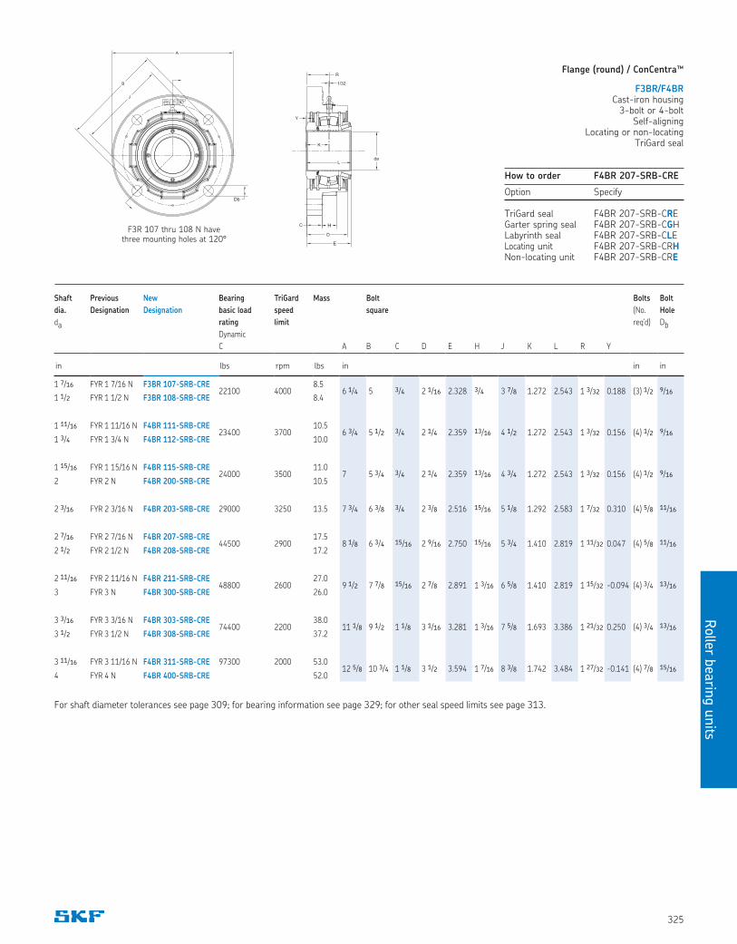
1 7/16 FYR 1 7/16 N F3BR 107-SRB-CRE22100 4000
8.56 1/4 5 3/4 2 1/16 2.328 3/4 3 7/8 1.272 2.543 1 3/32 0.188 (3) 1/2 9/16
1 1/2 FYR 1 1/2 N F3BR 108-SRB-CRE 8.4
1 11/16 FYR 1 11/16 N F4BR 111-SRB-CRE23400 3700
10.56 3/4 5 1/2 3/4 2 1/4 2.359 13/16 4 1/2 1.272 2.543 1 3/32 0.156 (4) 1/2 9/16
1 3/4 FYR 1 3/4 N F4BR 112-SRB-CRE 10.0
1 15/16 FYR 1 15/16 N F4BR 115-SRB-CRE24000 3500
11.07 5 3/4 3/4 2 1/4 2.359 13/16 4 3/4 1.272 2.543 1 3/32 0.156 (4) 1/2 9/16
2 FYR 2 N F4BR 200-SRB-CRE 10.5
2 3/16 FYR 2 3/16 N F4BR 203-SRB-CRE 29000 3250 13.5 7 3/4 6 3/8 3/4 2 3/8 2.516 15/16 5 1/8 1.292 2.583 1 7/32 0.310 (4) 5/8 11/16
2 7/16 FYR 2 7/16 N F4BR 207-SRB-CRE44500 2900
17.58 1/8 6 3/4 15/16 2 9/16 2.750 15/16 5 3/4 1.410 2.819 1 11/32 0.047 (4) 5/8 11/16
2 1/2 FYR 2 1/2 N F4BR 208-SRB-CRE 17.2
2 11/16 FYR 2 11/16 N F4BR 211-SRB-CRE48800 2600
27.09 1/2 7 7/8 15/16 2 7/8 2.891 1 3/16 6 5/8 1.410 2.819 1 15/32 -0.094 (4) 3/4 13/16
3 FYR 3 N F4BR 300-SRB-CRE 26.0
3 3/16 FYR 3 3/16 N F4BR 303-SRB-CRE74400 2200
38.011 1/8 9 1/2 1 1/8 3 1/16 3.281 1 3/16 7 5/8 1.693 3.386 1 21/32 0.250 (4) 3/4 13/16
3 1/2 FYR 3 1/2 N F4BR 308-SRB-CRE 37.2
3 11/16 FYR 3 11/16 N F4BR 311-SRB-CRE 97300 2000 53.012 5/8 10 3/4 1 1/8 3 1/2 3.594 1 7/16 8 3/8 1.742 3.484 1 27/32 -0.141 (4) 7/8 15/16
4 FYR 4 N F4BR 400-SRB-CRE 52.0
Flange (round) / ConCentra™
F3BR/F4BRCast-iron housing
3-bolt or 4-boltSelf-aligning
Locating or non-locatingTriGard seal
For shaft diameter tolerances see page 309; for bearing information see page 329; for other seal speed limits see page 313.
F3R 107 thru 108 N havethree mounting holes at 120°
How to order F4BR 207-SRB-CRE
Option Specify
TriGard seal F4BR 207-SRB-CREGarter spring seal F4BR 207-SRB-CGHLabyrinth seal F4BR 207-SRB-CLELocating unit F4BR 207-SRB-CRHNon-locating unit F4BR 207-SRB-CRE
da
B
A
Db
J
R
da
1/32
Y
L
C
D
K
E
H
Roller
beari
ng u
nits
326
Shaft dia. da
Previous Designation
New Designation
Bearing basic load rating Dynamic C
TriGard speed limit
Mass A
Bolt square B
C
D
E
F
G
H
J *
K
L
R
Y
Bolts (No. req’d)
Bolt Hole Db
in lbs rpm lbs in in in
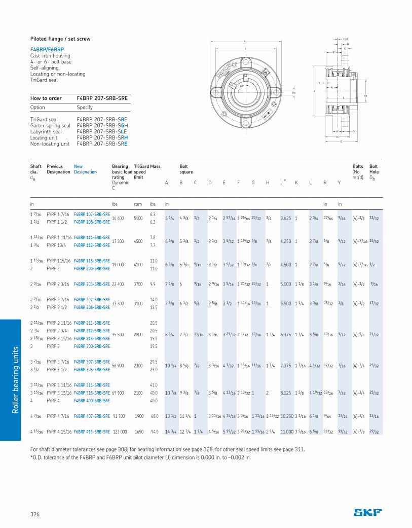
1 7/16 FYRP 1 7/16 F4BRP 107-SRB-SRE16 600 5100
6.35 1/4 4 3/8 1/2 2 1/4 2 57/64 1 25/64 23/32 3/4 3.625 1 2 3/4 27/64 9/64 (4)-3/8 13/32
1 1/2 FYRP 1 1/2 F4BRP 108-SRB-SRE 6.3
1 11/16 FYRP 1 11/16 F4BRP 111-SRB-SRE17 300 4500
7.86 1/8 5 1/8 1/2 2 1/2 3 5/32 1 19/32 5/8 7/8 4.250 1 2 7/8 5/8 9/32 (4)-7/16 15/32
1 3/4 FYRP 13/4 F4BRP 112-SRB-SRE 7.7
1 15/16 FYRP 115/16 F4BRP 115-SRB-SRE19 000 4100
11.06 3/8 5 3/8 9/16 2 1/2 3 5/32 1 19/32 5/8 7/8 4.500 1 2 7/8 5/8 9/32 (4)-7/16 1/2
2 FYRP 2 F4BRP 200-SRB-SRE 11.0
2 3/16 FYRP 2 3/16 F4BRP 203-SRB-SRE 22 400 3700 9.9 7 1/8 6 9/16 2 9/16 3 5/16 1 21/32 23/32 1 5.000 1 1/8 3 1/8 9/16 3/16 (4)-1/2 9/16
2 7/16 FYRP 2 7/16 F4BRP 207-SRB-SRE33 300 3100
14.07 5/8 6 1/2 5/8 2 5/8 3 1/2 1 11/16 13/16 1 5.500 1 1/4 3 3/8 15/32 1/8 (4)-1/2 17/32
2 1/2 FYRP 2 1/2 F4BRP 208-SRB-SRE 13.5
2 11/16 FYRP 2 11/16 F4BRP 211-SRB-SRE
35 500 2800
20.5
8 3/4 7 1/2 11/16 3 1/8 3 29/32 2 1/32 13/16 1 1/4 6.375 1 1/4 3 5/8 13/16 9/32 (4)-5/8 21/322 3/4 FYRP 2 3/4 F4BRP 212-SRB-SRE 20.5
2 15/16 FYRP 2 15/16 F4BRP 215-SRB-SRE 19.5
3 FYRP 3 F4BRP 300-SRB-SRE 19.5
3 7/16 FYRP 3 7/16 F4BRP 307-SRB-SRE56 900 2300
29.510 1/4 8 5/8 7/8 3 3/16 4 7/32 1 15/16 11/16 1 1/4 7.375 1 7/16 4 1/32 17/32 3/16 (4)-3/4 25/32
3 1/2 FYRP 3 1/2 F4BRP 308-SRB-SRE 29.0
3 11/16 FYRP 3 11/16 F4BRP 311-SRB-SRE
69 900 2100
41.0
10 7/8 9 3/8 7/8 3 5/8 4 13/16 2 13/32 1 2 8.125 1 5/8 4 19/32 13/16 7/32 (4)-3/4 25/323 15/16 FYRP 3 15/16 F4BRP 315-SRB-SRE 40.0
4 FYRP 4 F4BRP 400-SRB-SRE 40.0
4 7/16 FYRP 4 7/16 F6BRP 407-SRB-SRE 91 700 1900 68.0 13 1/2 11 3/4 1 3 11/16 4 15/16 3 3/16 1 11/16 1 15/32 10.250 3 1/16 6 1/8 9/64 13/16 (6)-3/4 13/16
4 15/16 FYRP 4 15/16 F6BRP 415-SRB-SRE 123 000 1650 94.0 14 3/4 12 3/4 1 1/4 4 5/16 5 19/32 3 21/32 1 11/16 2 1/4 11.000 3 5/16 6 5/8 11/32 11/32 (6)-7/8 29/32
Piloted flange / set screw
F4BRP/F6BRPCast-iron housing4- or 6- bolt baseSelf-aligningLocating or non-locatingTriGard seal
For shaft diameter tolerances see page 308; for bearing information see page 328; for other seal speed limits see page 311.
*O.D. tolerance of the F4BRP and F6BRP unit pilot diameter (J) dimension is 0.000 in. to –0.002 in.
How to order F4BRP 207-SRB-SRE
Option Specify
TriGard seal F4BRP 207-SRB-SREGarter spring seal F4BRP 207-SRB-SGHLabyrinth seal F4BRP 207-SRB-SLELocating unit F4BRP 207-SRB-SRHNon-locating unit F4BRP 207-SRB-SRE
R
da
1/32
Y
L
D
K
E
H G
J
C
F
62°
B
A
Db
Rolle
r bearin
g u
nits
327
Shaft dia. da
Previous Designation
New Designation
Bearing basic load rating Dynamic C
TriGard speed limit
Mass A
Bolt square B
C
D
E
F
G
H
J *
K
L
R
Y
Bolts (No. req’d)
Bolt Hole Db
in lbs rpm lbs in in in
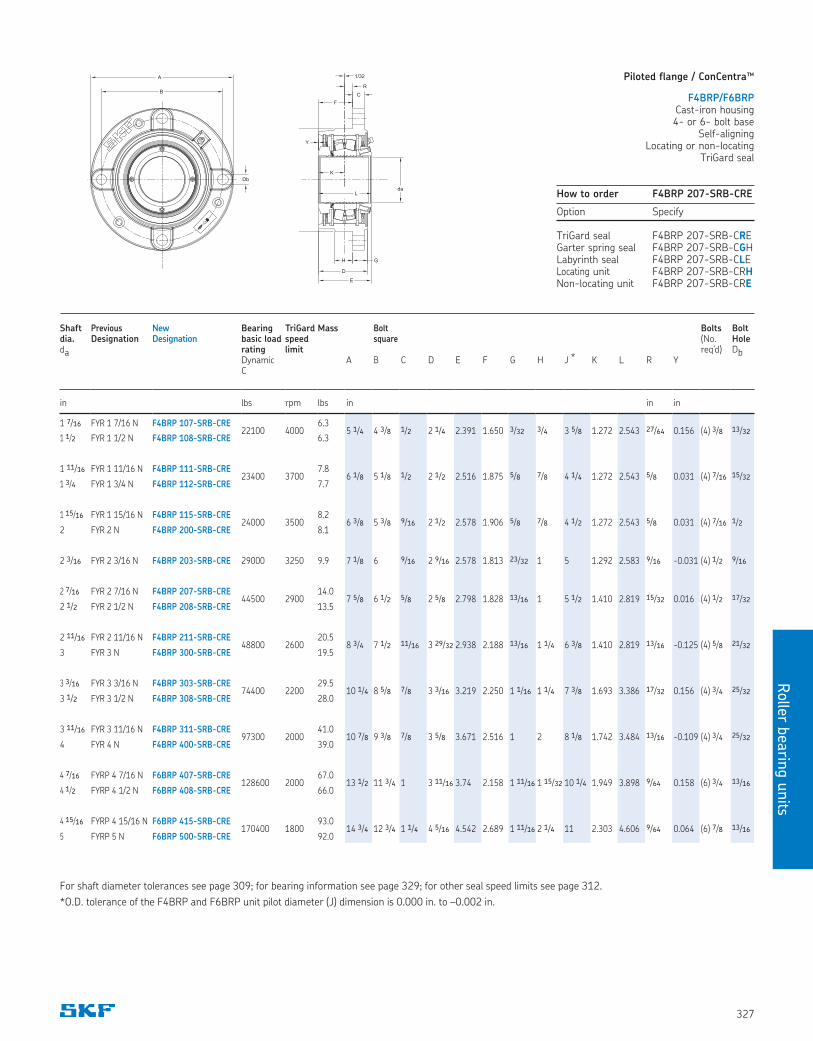
1 7/16 FYR 1 7/16 N F4BRP 107-SRB-CRE22100 4000
6.35 1/4 4 3/8 1/2 2 1/4 2.391 1.650 3/32 3/4 3 5/8 1.272 2.543 27/64 0.156 (4) 3/8 13/32
1 1/2 FYR 1 1/2 N F4BRP 108-SRB-CRE 6.3
1 11/16 FYR 1 11/16 N F4BRP 111-SRB-CRE23400 3700
7.86 1/8 5 1/8 1/2 2 1/2 2.516 1.875 5/8 7/8 4 1/4 1.272 2.543 5/8 0.031 (4) 7/16 15/32
1 3/4 FYR 1 3/4 N F4BRP 112-SRB-CRE 7.7
1 15/16 FYR 1 15/16 N F4BRP 115-SRB-CRE24000 3500
8.26 3/8 5 3/8 9/16 2 1/2 2.578 1.906 5/8 7/8 4 1/2 1.272 2.543 5/8 0.031 (4) 7/16 1/2
2 FYR 2 N F4BRP 200-SRB-CRE 8.1
2 3/16 FYR 2 3/16 N F4BRP 203-SRB-CRE 29000 3250 9.9 7 1/8 6 9/16 2 9/16 2.578 1.813 23/32 1 5 1.292 2.583 9/16 -0.031 (4) 1/2 9/16
2 7/16 FYR 2 7/16 N F4BRP 207-SRB-CRE44500 2900
14.07 5/8 6 1/2 5/8 2 5/8 2.798 1.828 13/16 1 5 1/2 1.410 2.819 15/32 0.016 (4) 1/2 17/32
2 1/2 FYR 2 1/2 N F4BRP 208-SRB-CRE 13.5
2 11/16 FYR 2 11/16 N F4BRP 211-SRB-CRE48800 2600
20.58 3/4 7 1/2 11/16 3 29/32 2.938 2.188 13/16 1 1/4 6 3/8 1.410 2.819 13/16 -0.125 (4) 5/8 21/32
3 FYR 3 N F4BRP 300-SRB-CRE 19.5
3 3/16 FYR 3 3/16 N F4BRP 303-SRB-CRE74400 2200
29.510 1/4 8 5/8 7/8 3 3/16 3.219 2.250 1 1/16 1 1/4 7 3/8 1.693 3.386 17/32 0.156 (4) 3/4 25/32
3 1/2 FYR 3 1/2 N F4BRP 308-SRB-CRE 28.0
3 11/16 FYR 3 11/16 N F4BRP 311-SRB-CRE97300 2000
41.010 7/8 9 3/8 7/8 3 5/8 3.671 2.516 1 2 8 1/8 1.742 3.484 13/16 -0.109 (4) 3/4 25/32
4 FYR 4 N F4BRP 400-SRB-CRE 39.0
4 7/16 FYRP 4 7/16 N F6BRP 407-SRB-CRE128600 2000
67.013 1/2 11 3/4 1 3 11/16 3.74 2.158 1 11/16 1 15/32 10 1/4 1.949 3.898 9/64 0.158 (6) 3/4 13/16
4 1/2 FYRP 4 1/2 N F6BRP 408-SRB-CRE 66.0
4 15/16 FYRP 4 15/16 N F6BRP 415-SRB-CRE170400 1800
93.014 3/4 12 3/4 1 1/4 4 5/16 4.542 2.689 1 11/16 2 1/4 11 2.303 4.606 9/64 0.064 (6) 7/8 13/16
5 FYRP 5 N F6BRP 500-SRB-CRE 92.0
Piloted flange / ConCentra™
F4BRP/F6BRPCast-iron housing4- or 6- bolt base
Self-aligningLocating or non-locating
TriGard seal
For shaft diameter tolerances see page 309; for bearing information see page 329; for other seal speed limits see page 312.
*O.D. tolerance of the F4BRP and F6BRP unit pilot diameter (J) dimension is 0.000 in. to –0.002 in.
How to order F4BRP 207-SRB-CRE
Option Specify
TriGard seal F4BRP 207-SRB-CREGarter spring seal F4BRP 207-SRB-CGHLabyrinth seal F4BRP 207-SRB-CLELocating unit F4BRP 207-SRB-CRHNon-locating unit F4BRP 207-SRB-CRE
B
A
Db
R
da
1/32
Y
L
D
K
E
H G
J
C
F
Roller
beari
ng u
nits
328
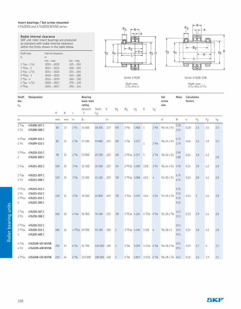
Radial internal clearanceSKF unit roller insert bearings are produced as standard with radial internal clearance within the limits shown in the table below
Shaft Designation Bearing Set Mass Calculation
dia. basic load screw factors
da rating size
dynamic Static b B1 B2 d1 K d2D B L C C0
in mm mm in lb in in lb e Y1 Y2 Y0
1 7/16 476208-107 C 80 23 2 3/4 16 600 18 300 .219 5/8 2 3/8 1.908 1 2 3/8 3/8-24 x 1/2
2.500.28 2.4 3.6 2.5
1 1/2 476208-108 C 2.45
1 11/16 476209-111 C 85 23 2 7/8 17 300 19 800 .219 5/8 2 3/8 2.157 3/8-24 x 1/2
2.750.26 2.6 3.9 2.5
1 3/4 476209-112 C 1 2 5/8 2.70
1 15/16 476210-115 C 90 23 2 7/8 19 000 22 500 .219 5/8 2 15/32 2.357 1 2 7/8 3/8-24 x 1/2
2.900.24 2.8 4.2
2 476210-200 C 2.80 2.8
2 3/16 476211-203 C 100 25 3 1/8 22 400 26 500 .219 3/4 2 23/32 2.600 11/8 3 1/4 3/8-24 x 1/2 3.90 0.24 2.8 4.2 2.8
2 7/16 476213-207 C120 31 3 3/8 33 300 41 100 .219 7/8 2 15/16 3.088 11/4 4 1/2-20 x 3/4
6.750.24 2.8 4.2 2.8
2 1/2 476213-208 C 6.75
2 11/16 476215-211 C
130 31 3 5/8 35 500 46 800 .219 7/8 3 1/16 3.491 11/4 4 1/2 1/2-20 x 7/8
9.35
0.22 3 4.6 2.83 3/4 476215-212 C 9.35
2 15/16 476215-215 C 9.35
3 476215-300 C 9.35
3 7/16 476218-307 C160 40 4 1/32 56 900 76 400 .219 7/8 3 15/32 4.224 1 7/16 5 1/8 1/2-20 x 7/8
13.50.23 2.9 4.4 2.8
3 1/2 476218-308 C 13.5
3 11/16 476220-311 C 19.5
3 15/16 476220-315 C 180 46 4 19/32 69 900 93 300 .328 1 3 15/16 4.650 1 5/8 6 5/8-18 x 1 19.5 0.24 2.8 4.2 2.8
4 476220-400 C 19.5
4 7/16 476222B-407 B/VSB200 53 6 1/8 91 700 126 000 .328 1 5 1/8 5.029 3 1/16 6 1/8 5/8-18 x 7/8
29.50.25 2.7 4 2.5
4 1/2 476222B-408 B/VSB 29.5
4 15/16 476226B-415 B/VSB 230 64 6 5/8 123 000 180 000 .438 1 5 5/8 5.819 3 5/16 6 7/8 5/8-18 x 7/8 46.5 0.26 2.6 3.9 2.5
Series 4762B
Shaft sizes 17/16 thru 4
Shaft sizes 47/16 thru 415/16
Series 4762B-VSB
Shaft sizes Internal clearance
in in
min – max min – max
1 7/16 – 1 1/2 .0010 – .0020 .025 – .050
1 11/16 – 2 .0012 – .0022 .030 – .055
2 3/16 – 2 1/2 .0014 – .0026 .035 – .065
2 11/16 – 3 .0018 – .0031 .045 – .080
3 7/16 – 4 .0024 – .0039 .060 – .100
4 7/16 – 4 1/2 .0028 – .0047 .070 – .120
4 15/16 .0035 – .0057 .090 – .145
Insert bearings / Set screw-mounted4762(00) and 4762(00) B/VSB series
Rolle
r bearin
g u
nits
329
Shaft Designation Bearing Mass No. Calculation
dia. basic load mounting factors
da rating screws
dynamic Static b d2 B1 (M6X1)
D B L C C0
in (mm) mm mm in lb in mm in lb qty e Y1 Y2 Y0
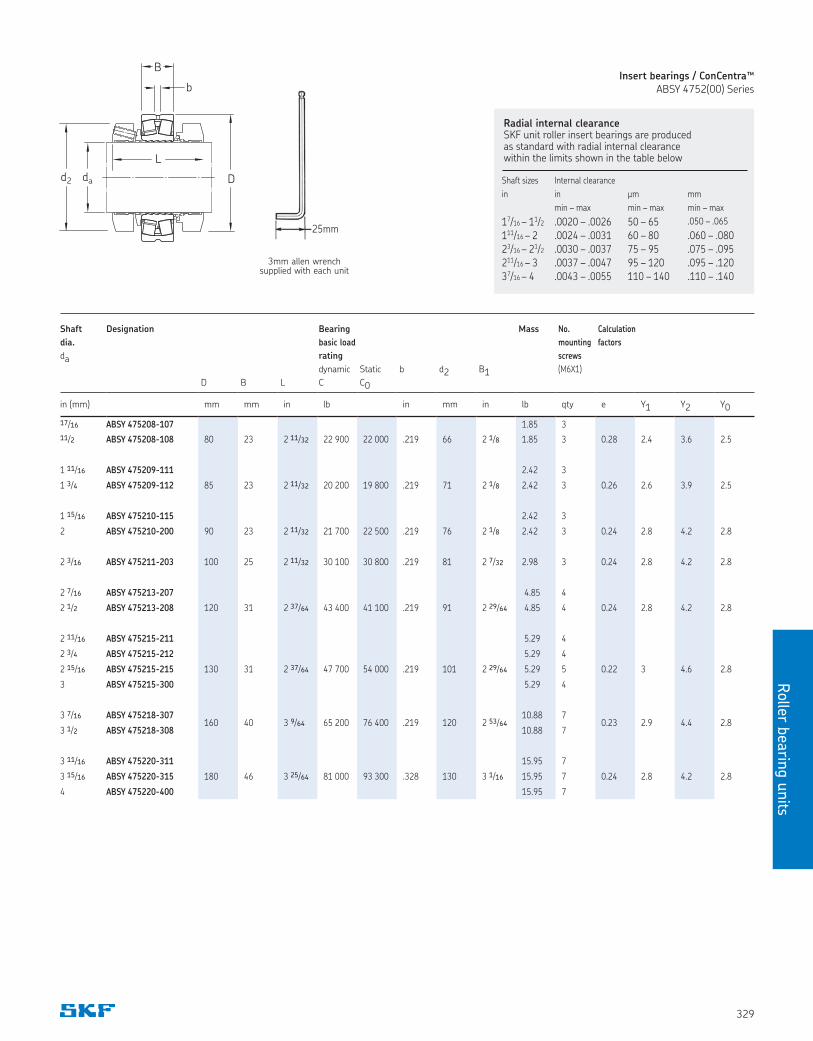
17/16 ABSY 475208-107 1.85 3
11/2 ABSY 475208-108 80 23 2 11/32 22 900 22 000 .219 66 2 1/8 1.85 3 0.28 2.4 3.6 2.5
1 11/16 ABSY 475209-111 2.42 3
1 3/4 ABSY 475209-112 85 23 2 11/32 20 200 19 800 .219 71 2 1/8 2.42 3 0.26 2.6 3.9 2.5
1 15/16 ABSY 475210-115 2.42 3
2 ABSY 475210-200 90 23 2 11/32 21 700 22 500 .219 76 2 1/8 2.42 3 0.24 2.8 4.2 2.8
2 3/16 ABSY 475211-203 100 25 2 11/32 30 100 30 800 .219 81 2 7/32 2.98 3 0.24 2.8 4.2 2.8
2 7/16 ABSY 475213-207 4.85 4
2 1/2 ABSY 475213-208 120 31 2 37/64 43 400 41 100 .219 91 2 29/64 4.85 4 0.24 2.8 4.2 2.8
2 11/16 ABSY 475215-211 5.29 4
2 3/4 ABSY 475215-212 5.29 4
2 15/16 ABSY 475215-215 130 31 2 37/64 47 700 54 000 .219 101 2 29/64 5.29 5 0.22 3 4.6 2.8
3 ABSY 475215-300 5.29 4
3 7/16 ABSY 475218-307160 40 3 9/64 65 200 76 400 .219 120 2 53/64
10.88 70.23 2.9 4.4 2.8
3 1/2 ABSY 475218-308 10.88 7
3 11/16 ABSY 475220-311 15.95 7
3 15/16 ABSY 475220-315 180 46 3 25/64 81 000 93 300 .328 130 3 1/16 15.95 7 0.24 2.8 4.2 2.8
4 ABSY 475220-400 15.95 7
3mm allen wrench supplied with each unit
Radial internal clearanceSKF unit roller insert bearings are produced as standard with radial internal clearance within the limits shown in the table below
Shaft sizes Internal clearance
in in µm mm
min – max min – max min – max
17/16 – 11/2 .0020 – .0026 50 – 65 .050 – .065
111/16 – 2 .0024 – .0031 60 – 80 .060 – .08023/16 – 21/2 .0030 – .0037 75 – 95 .075 – .095211/16 – 3 .0037 – .0047 95 – 120 .095 – .12037/16 – 4 .0043 – .0055 110 – 140 .110 – .140
B
L
Ddad2
b
Insert bearings / ConCentra™ABSY 4752(00) Series
25mm
Roller
beari
ng u
nits
330
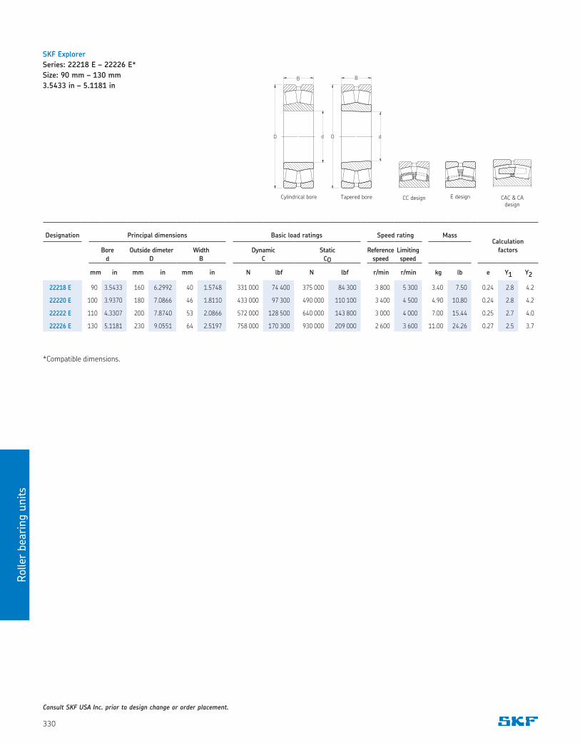
SKF Explorer
Series: 22218 E – 22226 E*
Size: 90 mm – 130 mm
3.5433 in – 5.1181 in
Consult SKF USA Inc. prior to design change or order placement.
Designation Principal dimensions Basic load ratings Speed rating MassCalculation
factorsBore
d
Outside dimeter
D
Width
B
Dynamic
C
Static
CO
Reference
speed
Limiting
speed
mm in mm in mm in N lbf N lbf r/min r/min kg lb e Y1 Y2
22218 E 90 3.5433 160 6.2992 40 1.5748 331 000 74 400 375 000 84 300 3 800 5 300 3.40 7.50 0.24 2.8 4.2
22220 E 100 3.9370 180 7.0866 46 1.8110 433 000 97 300 490 000 110 100 3 400 4 500 4.90 10.80 0.24 2.8 4.2
22222 E 110 4.3307 200 7.8740 53 2.0866 572 000 128 500 640 000 143 800 3 000 4 000 7.00 15.44 0.25 2.7 4.0
22226 E 130 5.1181 230 9.0551 64 2.5197 758 000 170 300 930 000 209 000 2 600 3 600 11.00 24.26 0.27 2.5 3.7
E design CAC & CA design
CC designCylindrical bore Tapered bore
*Compatible dimensions.
Rolle
r bearin
g u
nits
331
Notes

skfusa.com
® SKF is a registered trademark of the SKF Group.
© SKF USA Inc. 2019The contents of this publication are the copyright of the publisher and may not be reproduced (even extracts) unless prior written permission is granted. Every care has been taken to ensure the accuracy of the information contained in this publication but no liability can be accepted for any loss or damage whether direct, indirect or consequential arising out of the use of the information contained herein.
PUB 670-722 · March 2020 · 19013-Id12B


![; j ] : ; skf@ L e n Zdk SKF ... · PDF fileSKF Explorer spherical roller bearings ... and contaminants out of the bearing. SKF offers the widest assortment of sealed spherical roller](https://img.dokumen.tips/doc/110x75/5a9de2897f8b9aee528dae59/-j-skf-l-e-n-zdk-skf-explorer-spherical-roller-bearings-and-contaminants.jpg)