Embed Size (px)
Citation preview

HT-3500S-RF Dielectric Withstand Tester With Ground
Continuity Check

2

3
Dear Customer:
Congratulations! Compliance West USA is proud to present you with your
Dielectric Withstand Tester. Your instrument features a groundbreaking
logic-controlled circuit design and ergonomic panel, and represents the
latest in high voltage production line testing.
To fully appreciate all the features of your new meter, we suggest that you
take a few moments to review this manual. If the need arises, please don't
hesitate to call on us.
Thank you for your trust and confidence.
Rev.1.0, August 2015

4
Table of Contents
Section 1 .......................................................................................................................................6 Introduction and Safety ..................................................................................................6
An Introduction to Dielectric Withstand Testing with the HT-3500S-RF .......6 Safety Precautions ...........................................................................................6 Test Personnel .................................................................................................7 Testing Area ....................................................................................................7 Safety Techniques............................................................................................7 Safety Markings ...............................................................................................8
Using the HT-3500S-RF Dielectric Withstand Tester ...................................................9 Ground Continuity ...........................................................................................9
Ground Continuity Failures ...............................................................9 Defeating the Ground Continuity ......................................................9
Leakage Test ....................................................................................................10 Sporadic Leakage Current Failures ...................................................10 Chronic Leakage Current Failures .....................................................10
High Voltage Dielectric Withstand Test ..........................................................11 High Voltage Dielectric Withstand Test Failures ..............................11 High Voltage Discharge ....................................................................11
Testing Equipment with non-Standard Plugs or Pigtail Operation ..................11 Section 2 .......................................................................................................................................12
Specifications and Controls ...........................................................................................12 Introduction .....................................................................................................12 Panel Features ..................................................................................................14
Section 3 .......................................................................................................................................17 Operating Instructions ....................................................................................................17
Setting up your Tester ......................................................................................17 AC Line Voltage Requirements .......................................................................17 Fuse Replacement ............................................................................................18 Initial Checkout Procedure ..............................................................................18 High Voltage Performance Test ......................................................................18 Ground Continuity Performance Test ..............................................................18 Excess Leakage Performance Test ..................................................................19 Hipot Breakdown Performance Test ................................................................19 Setting up the HT-3500S-RF for Production Line Testing ..............................20 Factory Settings ...............................................................................................20 Display Setting Limits for Leakage, Time and Ground Continuity .................21 Adjustment of the High Voltage Level ............................................................21 Adjustment of the High Voltage Test Time .....................................................21 Adjustment of the Leakage Current Level .......................................................22 Adjustment of High Voltage Ramp Time ........................................................22 Setting the Ground Check Switch ....................................................................22 Adjustment of the Ground Continuity Limit ...................................................23 Adjustment of Ground Continuity Offset ........................................................23 Ground Continuity Resistance Measurement ..................................................24 Operation Techniques ......................................................................................24 Testing .............................................................................................................24 Testing a Device with 3-Wire Power Supply Cord..........................................25 Testing a Device with 2-Wire Power Supply Cord..........................................26
Section 4 .......................................................................................................................................28 Technical Assistance ......................................................................................................28
Contact Information .........................................................................................28 Section 5 .......................................................................................................................................29
Maintenance and Calibration .........................................................................................29
5
Service Information .........................................................................................29 Cleaning ...........................................................................................................29 Calibration Information ...................................................................................29 Calibration Procedure ......................................................................................29 Entering Calibration Mode ..............................................................................30 Calibration and Software Version Information ................................................30 Voltage Meter Verification ..............................................................................31 Voltage Meter Re-calibration ..........................................................................32 Leakage Meter Verification .............................................................................33 Leakage Current Re-Calibration ......................................................................34 Ground Continuity Verification .......................................................................35 Ground Continuity Re-Calibration ..................................................................36
6
Section 1
Introduction and Safety
An Introduction to Dielectric Withstand Testing with the HT-3500S-RF
The continuity test/dielectric withstand test is a production line test which is recognized by safety
agencies worldwide as a valid criterion of safe assembly of end-use equipment. The test ensures that the
primary circuit power and ground conductors were properly wired and connected for safe operation. It also
applies a high-voltage potential between power and ground conductors to make sure that no unintentional
leakage or arcing paths exist between power and ground. The test consists of a ground continuity check, a
leakage current check and a high voltage check. It is non-destructive to the equipment under test, and can
be accomplished in a short time.
The purpose of dielectric testing: Dielectric testing is a simple, non-destructive method of
verifying the adequacy of electrical insulation to withstand the sort of transients that can occur during
transient (surge) events. In addition, the dielectric test can verify that the insulation in question has an
adequate amount of performance "headroom". This is necessary to ensure that the insulation does not fail
because of degradation of the insulation due to aging, moisture, wear due to vibration, etc.
The method of dielectric testing: A high voltage (typically 1000 Volts or higher) is applied
between two conductors that are "supposed" to be electrically insulated from each other. If the two
conductors (an insulated "live" wire, and a metal enclosure, for example) are completely isolated from each
other, then the application of a large voltage difference between the two conductors will not allow current
to flow between the conductors. The insulation will "withstand" the application of a large voltage potential
between the two conductors - hence the term "dielectric withstand test". In general, there are two results of
the test that are considered a failure of the insulation: (1) excessive current flow during the test due to low
insulation resistance of the insulating material which separates the two conductors, and (2) an abrupt
dielectric breakdown due to electrical arcing or discharge, either through the insulation material, over the
surface of the insulation material, or a discharge through air.
The determination of a suitable test voltage: If the test voltage is too low, the insulation material
in question will not be adequately stressed during the test. This could cause inadequate insulation to pass
the test, and be considered acceptable. On the other hand, if the test voltage is too high, then the test could
cause permanent damage to an insulation material that is otherwise adequate for the application. A general
"rule of thumb" that is used for the testing of mains wiring which operates at voltages of 120-240Vac is
1000V plus two times the operating voltage. Using this rule, 120V wiring would be tested using a voltage
of 1240Vac.
Duration of the test: Generally, the test voltage is applied for one minute, in order to adequately
stress the insulation. Many standards allow the test duration to be reduced to 1 second for production-line
testing in order to accommodate large-volume production testing. In this case, standards quite often require
that the test voltage be increased by 20% in order to ensure that the shorter test duration of one second will
adequately test the insulation in question.
Safety Precautions
The dielectric withstand test generates voltages of up to 2500 Volts AC, up to 3500 Volts DC at
potentially lethal current levels. Currents of as little as 5 mA at 120V can cause death, and the HT-3500S-
RF is capable of generating 20mA AC at up to 2500 Volts and 5mA DC at up to 3500 Volts. The HT-
3500S-RF has been designed to minimize exposure to high voltages. However, the potential for serious
injury or death exists and personnel should be aware when they conduct this test.
Any use of this equipment other than as specified in this manual may result in a safety hazard.

7
Test Personnel
Personnel require special training to conduct the dielectric withstand test. They should understand
electrical fundamentals clearly, and be aware that high voltage is adept and creative at completing a path to
ground. Instructions should include a warning against any metal jewelry. Operators should not allow
others in the testing area, especially when tests are being conducted. Organization is to be stressed. The
operator should keep the area free of unused leads and equipment.
Testing Area
The area used for conducting the dielectric withstand test should be as remote as possible from
normal production line activities. Only personnel actually conducting the test should be allowed in the
area, and it should be taped or roped off to preclude casual entry by other employees. In addition, the area
should be marked "WARNING - HIGH VOLTAGE TESTING" or the equivalent to warn others of the
nature of the testing taking place.
The bench being used should be non-conductive, and any exposed metal parts should be tied
together and grounded. If a conductive surface must be used, it should be grounded.
Because of sparking during a dielectric test failure, it is not safe to conduct dielectric withstand
tests in combustible atmospheres.
It is imperative that a good ground be provided to the HT-3500S-RF unit. Before connecting the
HT-3500S-RF, ensure that a low-resistance ground is provided by the building wiring. If the HT-3500S-
RF is used on a high-resistance grounding circuit, dangerous high voltages may be present to the operator.
In addition, the power to the Testing Area should be provided with an easily reached shutoff switch which
can be actuated by personnel outside the area if needed.
Safety Techniques
The high voltage circuit of the HT-3500S-RF can be shut off at any time by pressing the RESET
button. The HT-3500S-RF has been provided with a Reset button to provide an unarmed "Standby" setting
when it is energized, but idle. When the red RESET light is lit the tester will not provide high voltage until
the RESET button and the TEST button have been pressed in order. To prevent inadvertent operation, the
operator should be instructed not to press the RESET button until the test is finish.
The HT-3500S-RF is equipped with a ground continuity check which will not allow high voltage
to be applied if the Test Return Lead is not properly connected. This is an important safety feature and
should not be defeated unless two wire products are being tested. In that event, it is imperative that the
operator make absolutely sure the Test Return Lead is properly connected to the equipment being tested. If
the lead is not properly connected, a dielectric withstand test failure may energize exposed dead metal of
the equipment being tested. Additionally, the HT-3500S-RF may not recognize the failure. The test will
continue for its normal length of time, and the HT-3500S-RF may show a "PASS", see connections for
more details.
8
The HT-3500S-RF has been designed for one-touch operation with the right hand. If possible, it
should be set up to the left and in front of the equipment under test. The equipment under test should be
connected to the HT-3500S-RF and then left alone by the operator. After the operator is clear of the Tester
and the equipment under test, he should press the RESET Button, then the TEST button, with his right
hand. This will allow the greatest separation between the operator and the test being conducted.
The HT-3500S-RF is designed to bleed the high voltage away after the test has concluded. In
order to ensure that any voltage present in the equipment being tested has been completely bled away, the
operator should not unplug the equipment under test from the HT-3500S-RF until the panel meter reads
zero volts.
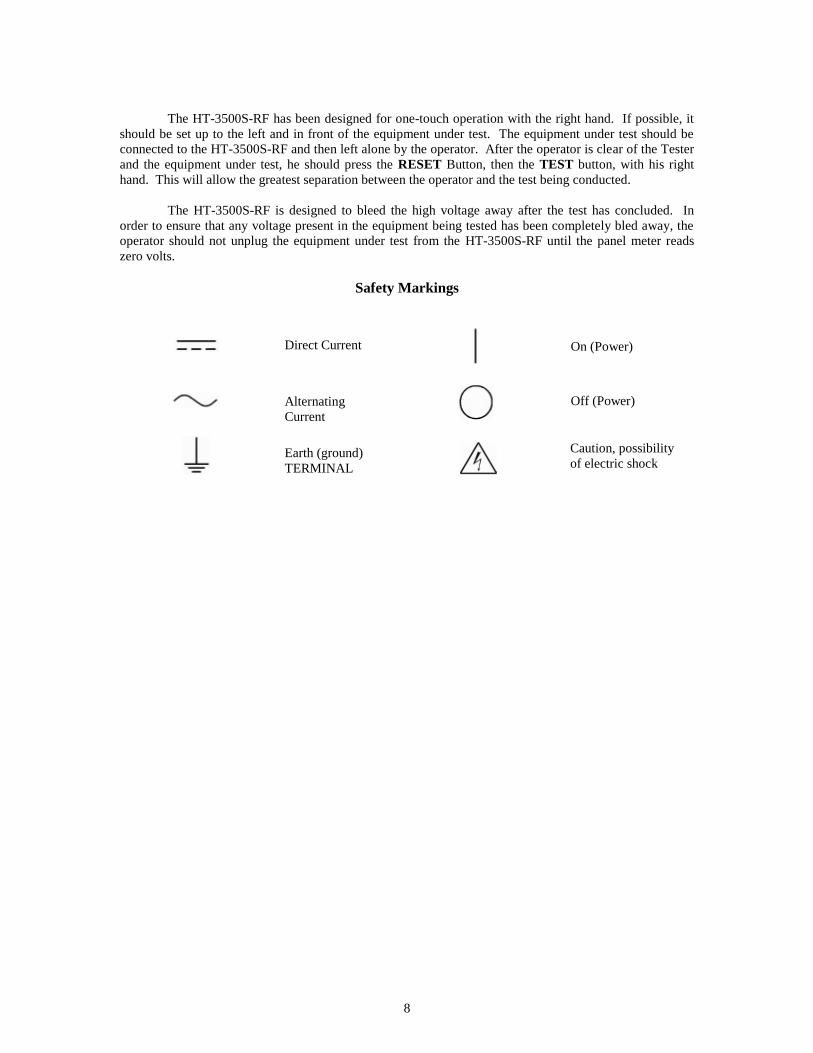
Safety Markings
Direct Current
Alternating
Current
Earth (ground)
TERMINAL
On (Power)
Off (Power)
Caution, possibility
of electric shock

9
Using the HT-3500S-RF Dielectric Withstand Tester
The dielectric withstand test involves high voltage and caution should be exercised when using the
tester. The return lead of the tester is connected to ground potential and when properly connected to the
equipment being tested, it will guard against the operator contacting high voltage. Always make sure the
return lead is firmly connected to exposed dead metal before start testing. To make sure if the connections
between the dielectric withstand tester and the equipment under test is correct, see the Testing section for
more detail. In the sections below, the three tests are explained.
Ground Continuity
The ground continuity test ensures that the grounding pin of the power supply cord is properly
connected to the exposed dead metal of the chassis. If this connection is absent, the exposed dead metal of
your product could be at line potential indefinitely after an internal wiring fault, causing risk of shock to
anyone touching it.
If the green Ground OK LED light is on, the connection between the grounding pin and the
exposed dead metal of the equipment being tested has a resistance lower than adjusted on the panel.
Ground Continuity Failures
If the red Ground Open LED light is on, the buzzer sounds, and the test is terminated. The
connection between the grounding pin and the exposed dead metal of the chassis has a resistance higher
than the indicated in the ground setting. This indicates a problem with the connection of the HT-3500S-RF
to the equipment being tested, or that the ground connection in the equipment being tested is defective.
The connection to the tester should be checked by removing the Test Return Lead clip from the equipment
under test and reconnecting it, taking care to make a good connection. The unit should then be retested. If
a failing result is repeated, the connection between the power supply cord ground pin and the chassis of the
equipment being tested should be checked and reworked until a passing result is obtained.
Defeating the Ground Continuity
The ground continuity can only be conducted on equipment using a three wire grounded power
supply cord. Some equipment, such as most portable lamps and all double insulated tools, have only a two
wire power supply cord, so the Ground Continuity test cannot be conducted.
Please note that defeating the Ground Continuity should not be done except when necessary to test
two-wire devices. The Ground Continuity feature provides an extra level of operator safety because high
voltage will not be applied if the Test Return Lead is not properly connected to the exposed dead metal of
the equipment being tested. If the Test Return Lead is not properly connected, a dielectric withstand failure
may energize exposed dead metal. Additionally, the HT-3500S-RF may not recognize the failure. The test
will continue for its normal length of time, and the HT-3500S-RF may show a "PASS".
To allow the HT-3500S-RF to test equipment using a two wire power supply cord, the Ground
Continuity test can be defeated by turning the panel Ground Check switch to the Off position. To remind
the operator that the Ground Continuity test is not being conducted, both the green Ground OK and red
Ground Open LED's will be lit continuously during the test. When testing with the Ground Check switch
in the Off position, the operator must ensure that the Test Return Lead is properly connected to exposed
dead metal of the equipment being tested for safety and to ensure that the HT-3500S-RF properly reports
all failures.
10
Leakage Test
The HT-3500S-RF leakage test uses a low-frequency circuit to check for excessive leakage
between primary power components and ground. There is not a specific leakage current level pass/fail
requirement at this time for most equipment, however, higher than normal leakage current on a particular
part may indicate an assembly or component problem in the primary circuit.
The leakage current is also monitored by the HT-3500S-RF to ensure that excessive leakage does
not keep the tester from developing full voltage required for the high voltage test. The HT-3500S-RF will
provide full voltage at any leakage current level up to 20 mA AC, 5mA DC. The leakage current trip level
is adjustable on the panel.
The leakage test is conducted by shorting the line and neutral conductors of the power supply cord
and applying high voltage between them and the exposed dead metal of the chassis of the equipment being
tested.
Excessive leakage current is not grounds for failure of the dielectric withstand test. Leakage
current is a normal result of capacitance in the primary circuit between neutral or line conductors and
ground. (In dielectric tests of some larger electric motors, leakage currents of as high as 95 mA are
considered acceptable by safety agencies.) However, leakage currents higher than normally anticipated for
a particular model should not be ignored. This indicates problems of low resistance up to a short circuit
between line/neutral and ground, and failures should be investigated. Failure modes are discussed below.
If the green Full Voltage LED light is on and the test continues, the leakage current is below the
limit set by the panel adjustment.
Sporadic Leakage Current Failures
If the red Excess Leakage LED light is on, the buzzer sounds, and the test is terminated, the
leakage current delivered to the equipment being tested was over the limit set by the panel adjustment. If
other equipment of the same type routinely passes this test, there may be a problem with the primary circuit
of the example being tested. The unit should be checked and reworked if necessary.
Chronic Leakage Current Failures
AC Dielectric Withstand testing, charges all primary circuit capacitors connected line to ground or
neutral to ground. The current flowing through these capacitors is defined as leakage current. If almost all
examples of a model of equipment are not passing the leakage current test, we recommend that the leakage
current limit be increased by resetting the leakage current level on the panel to a higher level.
If the leakage current adjustment of the HT-3500S-RF is set to 20mA AC and almost all examples
of the model being tested are still failing, the primary circuit capacitance of the equipment may be too high
to allow the AC dielectric withstand test to be used. This is due to the AC voltage charging all capacitors
connected between primary voltage and ground. If the overall value of these capacitors cause a leakage
current of more than 20mA to flow at the desired test voltage, the HT-3500S-RF cannot generate full
voltage, and cannot successfully conduct the dielectric withstand test.
However, a DC dielectric withstand test is acceptable for most categories of equipment and will
not charge the primary circuit capacitors. The DC test can be conducted by switching to DC. If the
problem was due to high leakage current on the capacitors of the circuit, the test should now be successful.

11
High Voltage Dielectric Withstand Test
This test checks for insulation system breakdowns between the primary and ground circuits. The
HT-3500S-RF uses a separate high-frequency transformer circuit to detect arc breakdowns.
The dielectric withstand test is conducted by shorting the line and neutral conductors of the power
supply cord and applying high voltage between them and the exposed dead metal of the chassis of the
equipment being tested. The duration of the test is controlled by the test time control on the back panel.
The test time is counted from the time the Full Voltage LED is lit to the completion of the test.
If the green Hipot Pass LED light is on, the test cycle has been successfully completed. The
equipment under test is in accordance with the preset test parameters. The HT-3500S-RF is ready to test
the next piece of equipment.
High Voltage Dielectric Withstand Test Failures
If the red Hipot Fail LED light is on, a problem has been found with the insulation between
primary and ground. The equipment under test should be examined, reworked and successfully tested
before being shipped.
High Voltage Discharge
The HT-3500S-RF is designed to discharge the high voltage after completion of the dielectric
withstand test. The equipment being tested should remain connected to the HT-3500S-RF until the voltage
has discharged to a safe level to protect the operator and also to ensure that there is no energy stored in the
tested equipment.
Testing Equipment with non-Standard Plugs or Pigtail Operation
The panel of the HT-3500S-RF is provided with a NEMA Type 5-15R receptacle, suitable for
testing cord-equipped single-phase products designed for use on a 15 amp branch circuit in North America.
For other types of products, a different receptacle type or pigtail leads may be required. Various adapters
and pigtail leads are available from Compliance West USA, or you can make your own, just make sure for
the correct configuration see the description of the outputs in the connections section. If tests of this type
are contemplated, call us for information.
12
Section 2
Specifications and Controls
Introduction
This manual contains complete operating, maintenance and calibration instructions for HT-3500S-
RF Dielectric Withstand Testers, please see Table 1 for specifications.
The instrument is a bench-type Dielectric Withstand Tester with AC and/or DC Output, designed
for production line testing. The HT-3500S-RF features automatic one button operation, with numerous
safety features designed to protect the operator:
The Return Lead is directly connected to ground potential for operator safety. Test can be
immediately terminated at any time by pressing the RESET button. Before the test can commence, the unit
must be armed by pressing the RESET Button. The test will not begin until the TEST button is pushed.
If a failure is encountered, the high voltage is immediately shut down, a buzzer sounds, and any
voltage stored in the equipment being tested is bled off by a resistor bank in the HT-3500S-RF unit. The
voltage discharge progress is shown by the panel meter. Failure modes are shown by the panel LED's for
quick troubleshooting.
Convenience and testing features include:
a. Test results are determined quickly, without operator intervention.
b. Operator instructions are printed on the panel for quick reference.
c. The HT-3500S-RF allows custom setups for Voltage Ramp time, Test time, Leakage limit and
Ground Continuity limit.
d. The Ground Continuity test can be defeated by a switch on the panel for testing of products using a
two wire power supply cord.
e. DC Voltage is discharged by a resistor bank within the HT-3500S-RF upon test completion.
Discharge progress is shown on the panel meter.
f. The HT-3500S-RF meets all safety agency criteria for automatic production line Dielectric
Withstand Testers.
g. Your Tester is warranted for a period of one year upon shipment of the instrument to the original
purchaser.
13
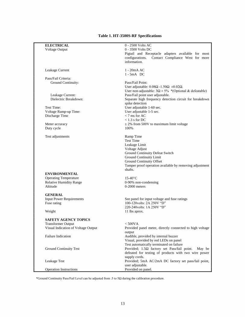
Table 1. HT-3500S-RF Specifications
ELECTRICAL
Voltage Output
0 - 2500 Volts AC
0 - 3500 Volts DC
Pigtail and Receptacle adapters available for most
configurations. Contact Compliance West for more
information.
Leakage Current 1 - 20mA AC
1 - 5mA DC
Pass/Fail Criteria:
Ground Continuity: Pass/Fail Point:
User adjustable: 0.08Ω -1.50Ω ±0.02Ω.
User non-adjustable: 3Ω ± 5% *(Optional & defeatable)
Leakage Current: Pass/Fail point user adjustable.
Dielectric Breakdown: Separate high frequency detection circuit for breakdown
spike detection
Test Time: User adjustable 1-60 sec.
Voltage Ramp-up Time: User adjustable 1-5 sec.
Discharge Time < 7 ms for AC
< 1.3 s for DC
Meter accuracy ± 2% from 500V to maximum limit voltage
Duty cycle 100%
Test adjustments Ramp Time
Test Time
Leakage Limit
Voltage Adjust
Ground Continuity Defeat Switch
Ground Continuity Limit
Ground Continuity Offset
Tamper proof operation available by removing adjustment
shafts.
ENVIRONMENTAL
Operating Temperature 15-40 C
Relative Humidity Range 0-90% non-condensing
Altitude 0-2000 meters
GENERAL
Input Power Requirements See panel for input voltage and fuse ratings
Fuse rating 100-120volts: 2A 250V “D”
220-240volts: 1A 250V “D”
Weight 11 lbs aprox.
SAFETY AGENCY TOPICS
Transformer Output < 500VA
Visual Indication of Voltage Output Provided panel meter, directly connected to high voltage
output
Failure Indication Audible, provided by internal buzzer
Visual, provided by red LEDs on panel
Test automatically terminated on failure
Ground Continuity Test Provided; 1.5Ω factory set Pass/fail point. May be
defeated for testing of products with two wire power
supply cords.
Leakage Test Provided; 5mA AC/2mA DC factory set pass/fail point,
user adjustable.
Operation Instructions Provided on panel.
*Ground Continuity Pass/Fail Level can be adjusted from .5 to 5Ω during the calibration procedure.
14
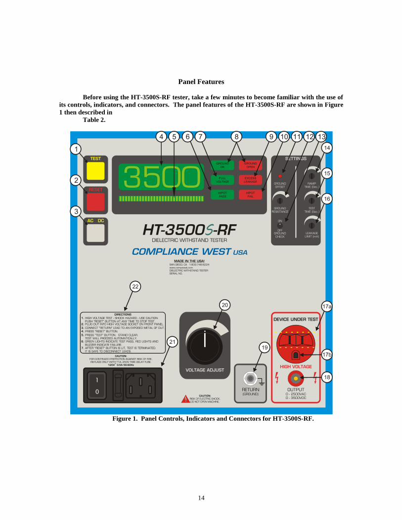
Panel Features
Before using the HT-3500S-RF tester, take a few minutes to become familiar with the use of
its controls, indicators, and connectors. The panel features of the HT-3500S-RF are shown in Figure
1 then described in
Table 2.
Figure 1. Panel Controls, Indicators and Connectors for HT-3500S-RF.

15
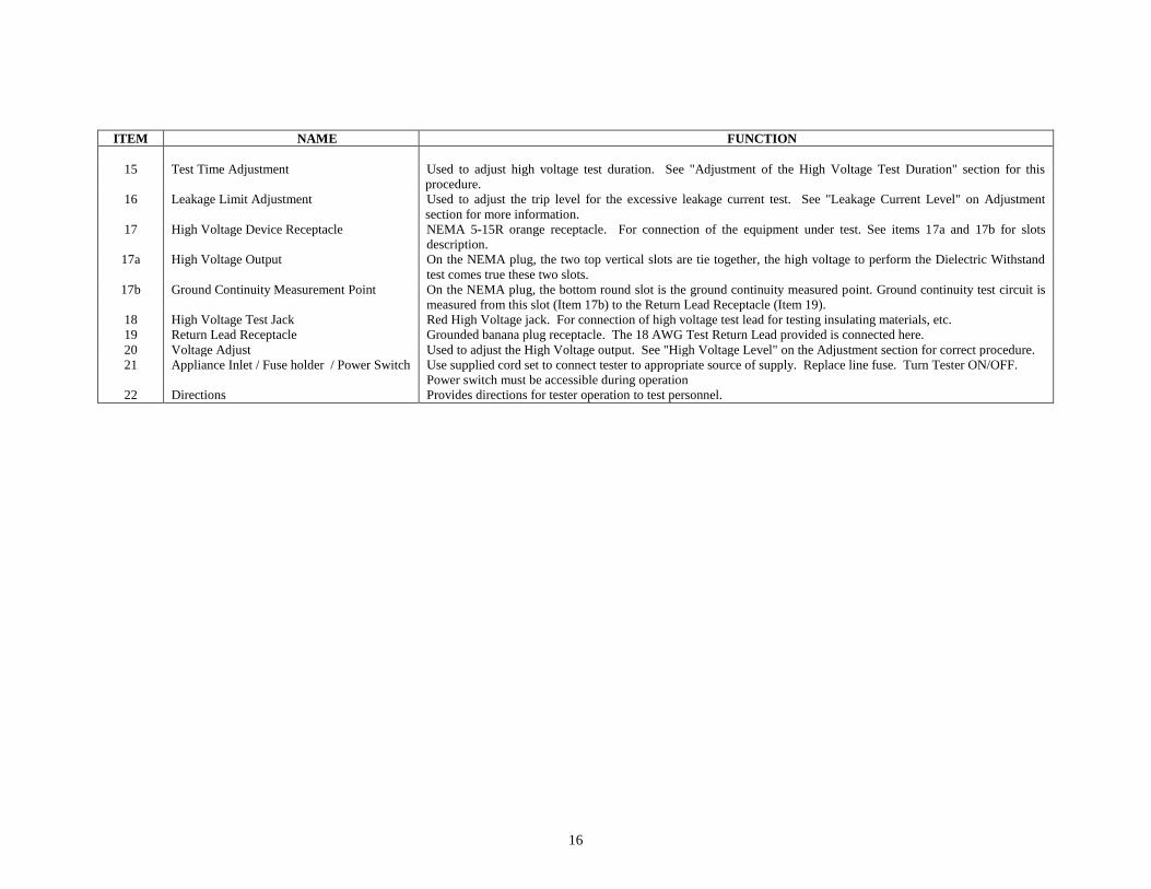
Table 2. Panel Controls, Indicators and Connectors.
ITEM NAME FUNCTION
1
TEST Button / Yellow Indicator When lit, indicates that the HT-3500S-RF tester is ready to test the connected equipment. The yellow TEST indicator
goes out when the TEST button is pressed.
2 RESET Button / Red Indicator When lit, indicates that the HT-3500S-RF tester is unarmed. This button must be pushed before the TEST button is
functional. When the RESET button is pressed, the red RESET indicator goes out and the yellow TEST indicator is
lit. PRESSING THE RESET BUTTON AT ANY TIME STOPS THE TEST.
3 AC/DC Switch
Selects AC or DC output. Changing switch setting does not change output until the next time the Reset button is
pushed.
4 Voltage Meter Provides visual indication to the operator of the actual output voltage of the HT-3500S-RF tester. Used to set the test
voltage level during the setup procedure.
5 Ramp Bar Graph LED’s Individual LED’s light in sequence from left to right as the test voltage ramps from zero to full voltage. LED’s turn
off (ramp back down) at end of test.
6 Hipot Pass LED At the end of the preset high voltage duration time, if no failures are encountered, the green light will light and the
test will terminate.
7 Full Voltage LED If full voltage is successfully reached, the Full Voltage LED will light and the high voltage duration timer starts.
8 Ground OK / Ground Open LED's Indicates result of Ground Continuity test between grounding pin of the line cord and exposed metal parts of the
equipment under test. If the ground path resistance it is higher than the indicated on the ground setting, or if the leads
are not properly connected, the red Ground Open LED will light, the internal buzzer will sound, and the test will be
terminated. If the ground circuit resistance is acceptable, the green continuity LED will light and the test will
continue. If the Ground Check switch is defeated by the operator, both LED's will be lit for the duration of the test.
9 Excess Leakage LED Indicates failure of leakage current test. If leakage current between the primary circuit and ground is higher than the
preset value, the red LED will light, the internal buzzer will sound, and the test will be terminated.
10 Hipot Fail LED Indicates failure of high voltage test. If arcing or a flashover of the insulation system between primary parts and
ground is encountered, the red breakdown LED will light, the internal buzzer will sound, and the test will be
terminated.
11 Ground Offset Button This button can perform two different functions. Pressing and holding it for 1 second, the HT-3500S-RF will measure
and display on the display the Ground Continuity resistance of the EUT under test. Pressing and holding the button
for 5 seconds will compensate the resistance of the test cables of fixture, see “Ground Continuity Offset Adjustment”
and “Ground Continuity Resistance Measurement” sections for more details.
12 Ground Resistance Setting Adjustment Used to adjust the Ground Continuity pass/fail point setting. See “Ground Continuity” on the Adjustment section for
more information.
13 Ground Check Switch Enables or disables the Ground Continuity test.
Turn ON for use with three-wire (grounded) power supply cords.
Turn OFF for use with two-wire power supply cords.
(When ON, conducts Ground Continuity test between the chassis and the grounding pin of the line cord of the
equipment being tested. When OFF, Ground Continuity test is bypassed for testing of double-insulated equipment
and other types of equipment without a grounding pin in the line cord.)
14 Ramp Time Adjustment Used to adjust the amount of time used to increase the high voltage from zero volts to the required level. See "High
Voltage Ramp Time" on Adjustment section for correct procedure.
16
ITEM NAME FUNCTION
15 Test Time Adjustment Used to adjust high voltage test duration. See "Adjustment of the High Voltage Test Duration" section for this
procedure.
16 Leakage Limit Adjustment Used to adjust the trip level for the excessive leakage current test. See "Leakage Current Level" on Adjustment
section for more information.
17 High Voltage Device Receptacle NEMA 5-15R orange receptacle. For connection of the equipment under test. See items 17a and 17b for slots
description.
17a High Voltage Output On the NEMA plug, the two top vertical slots are tie together, the high voltage to perform the Dielectric Withstand
test comes true these two slots.
17b Ground Continuity Measurement Point On the NEMA plug, the bottom round slot is the ground continuity measured point. Ground continuity test circuit is
measured from this slot (Item 17b) to the Return Lead Receptacle (Item 19).
18 High Voltage Test Jack Red High Voltage jack. For connection of high voltage test lead for testing insulating materials, etc.
19 Return Lead Receptacle Grounded banana plug receptacle. The 18 AWG Test Return Lead provided is connected here.
20 Voltage Adjust Used to adjust the High Voltage output. See "High Voltage Level" on the Adjustment section for correct procedure.
21 Appliance Inlet / Fuse holder / Power Switch Use supplied cord set to connect tester to appropriate source of supply. Replace line fuse. Turn Tester ON/OFF.
Power switch must be accessible during operation
22 Directions Provides directions for tester operation to test personnel.

17
Section 3
Operating Instructions
Setting up your Tester
The HT-3500S-RF tester is shipped in a special protective container that should prevent damage to
the instrument during shipping. Check the shipping order against the contents of the container and report
any damage or incomplete shipment to Compliance West USA. The container should include the following;
pictures are showed in Table 3:
- HT-3500S-RF Dielectric Withstand Tester
- 18 AWG Line Power Cord. Use only a power cord suitable in the jurisdiction where the
equipment is operated, and only if its ratings meet or exceed the ratings of the equipment.
- 18 AWG GL Test Lead (Alligator Clip/Banana Plug ends, black)
- Calibration Pin.
- Instruction Manual
Table 3. Shipment Cables & Connectors
Only accessories which meet the manufacturer’s specifications shall be used.
Connect this equipment to grounded outlet only. The integrity of the test system grounding is
dependent on building ground.
If reshipment of the instrument is necessary, please use the original shipping container. If the
original shipping container is not available, be sure that adequate protection is provided to prevent damage
during shipment. We recommend that the instrument be surrounded by at least three inches of shock-
absorbing material on all sides of the container.
Remove the tester from its container and place it on a test bench.
AC Line Voltage Requirements
AC line voltage requirements for your tester are noted on the panel of the instrument. Do not
connect the instrument to a different voltage source, use the power cord and make sure you have a ground
connection in your building before you start testing.
18 AWG Line Power
Cord, 6ft long
GL Return Test Lead, 4ft
long Calibration Pin
Red 18 AWG High
Voltage Test Lead, 4ft
long
18
Fuse Replacement
There is a user-replaceable fuse (F1) located on the panel of the instrument. It is located behind a
door in the Inlet-Power Switch-Fuse Holder device. The fuse rating is noted on the panel. Do not attempt
to replace it with a fuse of any other rating.
Use the following procedure to replace the fuse F1:
1. Turn the power switch to the O or OFF position.
2. Unplug the instrument from the source of supply.
3. Remove the power inlet cord from the instrument.
4. Using a small screwdriver, pry open the fuse holder door.
5. Replace the fuse with a new one of the correct rating.
6. Replace the fuse holder door and power inlet cord.
Initial Checkout Procedure
The following procedure will verify that the HT-3500S-RF is working correctly. We recommend
that this procedure be conducted periodically to ensure proper operation of the tester. (A Compliance West
HTT-1 or HTT-1R function tester may also be used to verify the HT-3500S-RF is working correctly).
The following items are needed to conduct this procedure:
- An 18 AWG GL test lead (Alligator Clip/Banana Plug ends, black).
- Ground continuity connector clip.
- A piece of none insulated jumper wire (Not supplied)
CAUTION
High voltage (up to 2500 Volts AC and up to 3500 Volts DC) generated by the HT-3500S-RF is
exposed during this test. A risk of shock exists. Exercise care when using the HT-3500S-RF.
High Voltage Performance Test
1. Disconnect all leads of the HT-3500S-RF panel.
2. Turn the Ground Check switch on the panel to the Off position.
3. Push the red RESET button. Verify the yellow TEST indicator is lit.
4. Push the yellow TEST button.
5. The Tester should conduct a test sequence. Confirm on the meter that the HT-3500S-RF can reach
the High voltage. At the end of the test, the Ground OK, Ground Open, Full Voltage, Hipot Pass,
and red RESET LED’s should be lit.
Ground Continuity Performance Test
1. Disconnect all leads of the HT-3500S-RF panel.
2. Turn the Ground Check switch on the panel to the On position.
3. Push the red RESET button, then the yellow TEST button.
4. The tester should sound the buzzer. The red Ground Open and red RESET LED’s should be lit.
5. Connect the supplied Ground Continuity Connector Tip into the bottom round slot of the orange
receptacle located on the panel or the GL Return Test Lead to the Ground Check receptacle.
6. Plug the supplied 18 AWG GL Test Lead (Alligator Clip/Banana Plug ends, black) into the
RETURN receptacle on the panel, then, connect the green alligator clip end to the Ground
Continuity Connector Tip previously connected on step 5.
7. Push the red RESET button and then the yellow TEST button.
8. The tester should conduct a test sequence. At test termination, the Ground OK, Full Voltage, Hipot
Pass, and Red RESET LED’s should be lit.
19
Excess Leakage Performance Test
1. Disconnect all leads of the HT-3500S-RF panel.
2. Turn the Ground Check switch on the panel to the Off position.
3. Plug the supplied 18 AWG GL Test Lead (Alligator Clip/Banana Plug ends, black) into the
RETURN receptacle on the panel, then, clamp with the green alligator clip the piece of none
insulated jumper wire.
4. Connect one end of the hookup wire to the clip of the black lead and insert the other end into one
of the vertical parallel slots in the DEVICE receptacle on the panel. Keep clear of the wire
while the test is in progress.
5. Push the red RESET button and then push the yellow TEST button.
6. The tester should conduct a test sequence, terminated with a buzzer. At test termination, the
Ground OK, Ground Open, Excess Leakage, and red RESET LED’s should be lit.
Hipot Breakdown Performance Test
Note: The following procedure tests the "Hipot Breakdown" circuit of the HT-3500S-RF unit and
involves high voltage. The only exposed parts during this test are at ground potential. However, the
voltage inside the High Voltage Device socket may be as much as 2500 volts AC or 3500 volts DC.
Proceed with caution.
1. Disconnect all leads of the HT-3500S-RF panel.
2. Turn the Ground Check switch on the panel to the Off position.
3. Plug the supplied 18 AWG GL Test Lead (Alligator Clip/Banana Plug ends, black) into the
RETURN receptacle on the panel, then, clamp with the green alligator clip the piece of none
insulated jumper wire.
4. Push the red RESET button, then the yellow TEST button. After the Full Voltage LED lights,
and before the Hipot Pass LED has lit, insert the other end of the hookup wire into one of the
vertical parallel slots in the High Voltage Device receptacle on the panel.
5. The test should immediately terminate with a buzzer. The Ground OK, Ground Open, Full
Voltage, Hipot Fail and red RESET LED’s should be lit.
Note: Depending on how the connection between the High Voltage Test Receptacle and the
hookup wire is made, the Excess Leakage LED may light, and in some instances, the Ground
OK LED may extinguish.
Passage of these tests indicates that the HT-3500S-RF tester is functioning properly and that it is
safe to use. If the results of the performance test are not in accordance with the above, service is required.
Remove the HT-3500S-RF tester from service and contact Compliance West USA, Inc. for servicing
information.

20
Setting up the HT-3500S-RF for Production Line Testing
This section describes procedures for setting the Leakage current level, Ground Continuity level,
high voltage Ramp Time, high Voltage level, and high Voltage Test Time. The HT-3500S-RF is calibrated
as shown below at the factory to be usable without adjustment in the majority of applications. If the factory
settings are acceptable, you may skip this section.
Factory Settings
The unit is configured as shown when shipped from Compliance West USA as it shown it in Table
4:
Table 4. Factory Settings.
AC Mode
Voltage Type: AC
Leakage Current Level: 5 mA
High Voltage Ramp Time: 1 second
High Voltage Level: 1200 Volts
High Voltage Test Time: 2 seconds
Ground Continuity Level 1.50Ω
DC Mode
Voltage Type: DC
Leakage Current Level: 2 mA
High Voltage Ramp Time: 1 second
High Voltage Level: 1700 Volts
High Voltage Test Time: 2 seconds
Ground resistance 1.50Ω
Adjustments of the various settings are shown below.
CAUTION
High voltage is generated by the HT-3500S-RF. Although the chassis of the equipment under test
is grounded by the HT-3500S-RF, a risk of shock exists. Exercise care when using the HT-3500S-RF.
NOTE
These adjustment procedures set the use parameters of the HT-3500S-RF. They do not take the
place of the annual calibration required by the safety agencies.

21
Display Setting Limits for Leakage, Time and Ground Continuity
To view the Test Duration, Leakage limit and Ground Continuity limit, hold down the RESET
button for 2 seconds, then, the meter will display “L” with the Leakage Limit value in mA. Hold down the
RESET button again for 2 seconds and the meter will display “d” with the Test Duration set time in
seconds. Hold down the RESET button again and the meter will display “r” with the Ground Continuity
limit in Ω. Hold down the RESET button again for 2 seconds to start over showing the Leakage Limit
value, see Figure 2.
Figure 2. HT-3500S-RF Test Settings
Adjustment of the High Voltage Level
This procedure controls the high voltage level used in the dielectric withstand test. It is specified
by safety agency personnel. Most safety agencies will allow a shorter test (usually 1 sec. vs. 1 min.) if the
voltage is increased by 20%. The HT-3500S-RF is factory set for 1200 volts AC or 1700 DC, a voltage
level used for the one second test for many types of equipment. Consult the safety agencies for the
required voltage level for the type of equipment being tested. If a different voltage level is required, use
this procedure to set it.
a. Disconnect all leads of the HT-3500S-RF panel.
b. Turn the Ground Check switch on the panel to the Off position.
c. Set the Test Time to at least 30 seconds, use the procedure of the High Voltage Test Time.
d. Connect the HT-3500S-RF to a correctly rated source of supply and turn the power switch to the I
or ON position. Push the RESET button. The yellow TEST indicator should light, indicating
that the HT-3500S-RF is ready to test.
e. Use the AC/DC button to select the type of output voltage.
f. After the TEST button is pressed, the voltage will ramp and hold. Using a driver set the Voltage
Adjust control on the panel to the desired voltage.
g. If tamperproof operation is desired, we suggest placing a calibration-style label over the voltage
adjust hole.
h. Check the position of the Ground Check Switch, and adjust the test time to the desired value
using the procedure of the High Voltage Test Time.
Adjustment of the High Voltage Test Time
This procedure sets the length of time the HT-3500S-RF will conduct the high voltage test. The
test time is specified by the safety agencies and is tied to the test voltage. Most safety agencies will allow a
much shorter test (usually 1 second vs 1 minute) if the voltage is increased by 20%. The HT-3500S-RF is
factory set for 2 seconds. Consult the safety agencies for the test time for the type of equipment being
tested. If a different test time is required, use this procedure to set it.
Connect the HT-3500S-RF to a correctly rated source of supply and turn the power switch to the I
or ON position. Push the RESET button. The yellow TEST indicator should light, indicating that the HT-
3500S-RF is ready to test. On the panel turn the Test Time potentiometer, as soon as the potentiometer
starts turning, the meter will display “d” and the value can be set in 1 second increments from 1 to 60
seconds.
If tamperproof settings are desired, the Test time Limit control shaft may be pulled away with a
slight tug. (It may be reinserted for future adjustments).

22
Adjustment of the Leakage Current Level
To set the leakage limit follow the steps below:
1. Connect the HT-3500S-RF to a correctly rated source of supply and turn the power switch to the I
or ON position. Push the RESET button. The yellow TEST indicator should light, indicating
that the HT-3500S-RF is ready to test.
2. Use the AC/DC button to select the type of output voltage.
3. On the panel turn the Leakage Limit potentiometer, as soon as the potentiometer starts turning,
the meter will start blinking, and it will show “L” with the new excess leakage limit set in the
scale of mA with increments 0.1 mA.
4. If tamperproof settings are desired, the Leakage Limit control shaft may be pulled away with a
slight tug. (It may be reinserted for future adjustments).
Adjustment of High Voltage Ramp Time
1. This procedure controls the amount of time used to ramp the high voltage to the required level.
The factory setting of two seconds is adequate for most situations. Use this procedure if
adjustment to a different ramp time within the range of 1 to 5 seconds is required.
2. Turn the Ground Check switch on the panel to the Off position.
3. Connect the HT-3500S-RF to a correctly rated source of supply and turn the power switch to the I
or ON position. Push the RESET button. The yellow TEST indicator should light, indicating
that the HT-3500S-RF is ready to test.
4. Make sure there are no test leads connected to the HT-3500S-RF. Push the TEST button.
5. When the TEST button is pressed, the voltage will ramp and hold. Adjust the Ramp Time
control on the panel until the desired ramp time is reached. The test can be terminated at any time
by pressing the RESET button.
6. If tamperproof settings are desired, the Ramp Time control shaft may be pulled away with a slight
tug. (It may be reinserted for future adjustments.)
7. Check the position of the Ground Check switch before testing.
Setting the Ground Check Switch
This switch controls whether the Ground Continuity Test is conducted between the chassis and the
power supply cord grounding pin of the unit being tested. The safety agencies require that this test be
conducted on all equipment using a three-wire power supply cord. For other types of equipment, such as
some portable lamps and all double-insulated equipment, there are only two wires in the power supply cord
and the ground continuity check is waived by the safety agencies.
If the power supply cord of the equipment being tested has only two pins, the Ground Check
switch should be set to the Off position. When the Ground Check switch is turned Off, both the green
Ground OK and red Ground Open LED's on the panel are lit as a reminder to the operator that the ground
continuity test is not being conducted.
If the power supply cord of the equipment being tested has three pins, the Ground Check switch
should be set to the On position.
When testing with the Ground Check switch Off, the operator must ensure that the Return lead
is properly connected to exposed dead metal of the equipment being tested for safety and to ensure that the
HT-3500S-RF properly reports all failures.
The small size of the Ground Check switch will allow a calibration-type adhesive label to be
placed over it to allow for tamper-proof operation.
23
Adjustment of the Ground Continuity Limit
To set the ground continuity limit follow the steps below:
On the panel turn the Ground Resistance potentiometer, as soon as the potentiometer starts
turning, the meter will start blinking, displaying the letter “r” with the new limit value in
If tamperproof settings are desired, the Ground Resistance control shaft may be pulled away
with a slight tug. (It may be reinserted for future adjustments).
Adjustment of Ground Continuity Offset
When the Ground Continuity test is activated, the offset function may used to compensate for lead
and test fixture resistance during the Ground Continuity test. To set the Ground Continuity offset follow the
steps bellow:
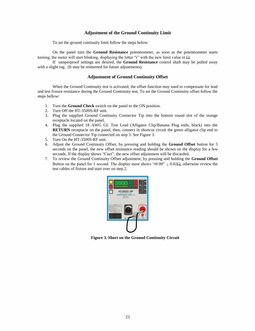
1. Turn the Ground Check switch on the panel to the ON position.
2. Turn Off the HT-3500S-RF unit.
3. Plug the supplied Ground Continuity Connector Tip into the bottom round slot of the orange
receptacle located on the panel.
4. Plug the supplied 18 AWG GL Test Lead (Alligator Clip/Banana Plug ends, black) into the
RETURN receptacle on the panel, then, connect in shortcut circuit the green alligator clip end to
the Ground Connector Tip connected on step 3. See Figure 3.
5. Turn On the HT-3500S-RF unit.
6. Adjust the Ground Continuity Offset, by pressing and holding the Ground Offset button for 5
seconds on the panel, the new offset resistance reading should be shown on the display for a few
seconds. If the display shows “Cnct”, the new offset adjustment will be discarded.
7. To review the Ground Continuity Offset adjustment, by pressing and holding the Ground Offset
Button on the panel for 1 second. The display most shows “r0.00” 0.02 , otherwise review the
test cables of fixture and start over on step 2.
Figure 3. Short on the Ground Continuity Circuit

24
Ground Continuity Resistance Measurement
NOTE
It is recommended to perform the adjustment of the Ground Continuity Offset before measuring
the Ground Continuity Resistance.
To measure the Ground Continuity Resistance follows the next steps:
a. Turn Off the HT-3500S-RF unit.
b. Turn the Ground Check switch on the panel to the ON position.
c. Connect the EUT fixture to the Return and Ground Continuity Measurement point of the HT-3500S-
RF unit.
d. Turn On the HT-3500S-RF unit.
e. Press and hold for 1 second the Ground Offset button, located on the panel. The display will show
for a few seconds the Ground Continuity resistance of the EUT fixture connected on step 3.
f. Only if the Ground Continuity resistance measurement is more than 1.50 , the display will show
“OPEn”.
Operation Techniques
The following paragraphs describe how to operate the HT-3500S-RF tester. Before proceeding
with testing, the HT-3500S-RF tester should be set up for production line testing. See Section above before
continuing.
CAUTION:
High voltage is generated by the HT-3500S-RF. Although the chassis of the equipment under test
is grounded by the HT-3500S-RF, a risk of shock exists. Exercise care when using the HT-3500S-RF.
Testing
This section describes how the HT-3500S-RF tester is used to conduct a Hipot test. Before
continuing, we recommend that you read Section 1, "An Introduction to Dielectric Withstand Testing with
the HT-3500S-RF". It contains valuable safety, operation, and test result evaluation information which can
help you conduct the test safely and correctly. The test can be stopped immediately at any time by pressing
the red RESET button on the panel.
25
Testing a Device with 3-Wire Power Supply Cord
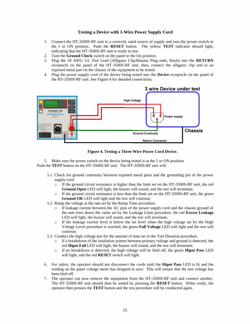
1. Connect the HT-3500S-RF unit to a correctly rated source of supply and turn the power switch to
the I or ON position. Push the RESET button. The yellow TEST indicator should light,
indicating that the HT-3500S-RF unit is ready to test.
2. Turn the Ground Check switch on the panel to the On position.
3. Plug the 18 AWG GL Test Lead (Alligator Clip/Banana Plug ends, black) into the RETURN
receptacle on the panel of the HT-3500S-RF unit, then, connect the alligator clip end to an
exposed metal part on the chassis of the equipment to be tested.
4. Plug the power supply cord of the device being tested into the Device receptacle on the panel of
the HT-3500S-RF unit. See Figure 4 for detailed connections.
Figure 4. Testing a Three Wire Power Cord Device.
5. Make sure the power switch on the device being tested is in the 1 or ON position.
Push the TEST button on the HT-3500S-RF unit. The HT-3500S-RF unit will:
5.1 Check for ground continuity between exposed metal parts and the grounding pin of the power
supply cord.
o If the ground circuit resistance is higher than the limit set on the HT-3500S-RF unit, the red
Ground Open LED will light, the buzzer will sound, and the test will terminate.
o If the ground circuit resistance is less than the limit set on the HT-3500S-RF unit, the green
Ground OK LED will light and the test will continue.
5.2 Ramp the voltage at the rate set by the Ramp Time procedure.
o If leakage current between the AC pins of the power supply cord and the chassis ground of
the unit rises above the value set by the Leakage Limit procedure, the red Excess Leakage
LED will light, the buzzer will sound, and the test will terminate.
o If the leakage current level is below the set level when the high voltage set by the High
Voltage Level procedure is reached, the green Full Voltage LED will light and the test will
continue.
5.3 Conduct the high voltage test for the amount of time set in the Test Duration procedure.
o If a breakdown of the insulation system between primary voltage and ground is detected, the
red Hipot Fail LED will light, the buzzer will sound, and the test will terminate.
o If no breakdown is detected, the high voltage will be bled off, the green Hipot Pass LED
will light, and the red RESET switch will light.
6. For safety, the operator should not disconnect the cords until the Hipot Pass LED is lit and the
reading on the panel voltage meter has dropped to zero. This will ensure that the test voltage has
been bled off.
7. The operator can now remove the equipment from the HT-3500S-RF unit and connect another.
The HT-3500S-RF unit should then be armed by pressing the RESET button. When ready, the
operator then presses the TEST button and the test procedure will be conducted again.

26
Testing a Device with 2-Wire Power Supply Cord
1. Connect the HT-3500S-RF unit to a correctly rated source of supply and turn the power switch to
the I or ON position. Push the RESET button. The yellow TEST indicator should light,
indicating that the HT-3500S-RF unit is ready to test.
2. Turn the Ground Check switch on the panel to the Off position.
3. Plug the 18 AWG GL Test Lead (Alligator Clip/Banana Plug ends, black) into the RETURN
receptacle on the panel of the HT-3500S-RF unit, then, connect the alligator clip end to an
exposed metal part on the chassis of the equipment to be tested.
4. Plug the power supply cord of the device being tested into the Device receptacle on the panel of
the HT-3500S-RF unit. See Figure 5 for detailed connections.
Figure 5. Testing a Two Wire Power Cord Device
5. Make sure the power switch on the device being tested is in the 1 or ON position.
Push the TEST button on the HT-3500S-RF unit. The HT-3500S-RF unit will:
5.1 Ramp the voltage at the rate set by the Ramp Time procedure.
o If leakage current between the AC pins of the power supply cord and the chassis ground of
the unit rises above the value set by the Leakage Limit procedure, the red Excess Leakage
LED will light, the buzzer will sound, and the test will terminate.
o If the leakage current level is below the set level when the high voltage set by the High
Voltage Level procedure is reached, the green Full Voltage LED will light and the test will
continue.
5.2 Conduct the high voltage test for the amount of time set in the Test Duration procedure.
o If a breakdown of the insulation system between primary voltage and ground is detected,
the red Hipot Fail LED will light, the buzzer will sound, and the test will terminate.
o If no breakdown is detected, the high voltage will be bled off, the green Hipot Pass LED
will light, and the red RESET switch will light.
6. For safety, the operator should not disconnect the cords until the Hipot Pass LED is lit and the
reading on the panel voltage meter has dropped to zero. This will ensure that the test voltage has
been bled off.
7. The operator can now remove the equipment from the HT-3500S-RF unit and connect another.
The HT-3500S-RF unit should then be armed by pressing the RESET button. When ready, the
operator then presses the TEST button and the test procedure will be conducted again.

27

28
Section 4
Technical Assistance
Contact Information
Technical Assistance from Compliance West USA is available:
Phone: (800) 748-6224
Hours: 8:30 AM - 4:30 PM Pacific Time.
Also available on our web site at: www.compwest.com
Contact:
Compliance West USA
650 Gateway Center Way Suite D
San Diego, CA 92102
United States of America.
Phone: (619) 878-9696
FAX: (619) 794-0404
29
Section 5
Maintenance and Calibration
WARNING: THESE SERVICE INSTRUCTIONS ARE FOR USE BY QUALIFIED PERSONNEL ONLY.
TO AVOID ELECTRIC SHOCK, DO NOT PERFORM ANY SERVICING OTHER THAN THAT
CONTAINED IN THE OPERATING INSTRUCTIONS UNLESS YOU ARE QUALIFIED TO DO SO.
Service Information
The HT-3500S-RF Tester is warranted to the original purchaser for a period of 1 year. This
warranty does not cover problems due to misuse or neglect.
Malfunctions which occur within the limits of the warranty will be corrected at no charge. Mail
the instrument post paid to the manufacturer. Dated proof of purchase is required for all in-warranty
repairs.
The manufacturer is also available for calibration and/or repair of instruments that are beyond their
warranty period. Contact the manufacturer for a cost quotation. Ship the instrument and your remittance
according to the instructions given by the manufacturer.
Cleaning
CAUTION
Do not use aromatic hydrocarbons or chlorinated solvents for cleaning. These solutions will
react with the plastic materials used in the instrument.
Clean the panel and case with a mild solution of detergent and a damp sponge. Clean dust from the
PWB with clean, dry, low pressure (<20 psi).
Calibration Information
The HT-3500S-RF series tester has been fully calibrated at the factory in accordance to our
published specifications. It is recommended that you have this instrument re-calibrated and safety check
done at least once per year.
Contact Compliance West USA for the latest calibration procedure and have ready the serial
number of the tester.
Calibration Procedure
The Calibration Procedure should be performed annually and any time your instrument has been
repaired. The calibration procedure consists of the next sections:
1) Entering Calibration Mode.
2) Calibration and Software Version Information.
3) Voltage Meter Verification.
4) Voltage Meter Re-calibration.
5) Leakage Meter Verification.
6) Leakage Current Re-Calibration.
7) Ground Continuity Verification.
8) Ground Continuity Re-Calibration.

30
NOTE
Allow the instrument to stabilize for approximately five minutes. Perform all calibration
adjustments at an ambient temperature of 23 C 5 C (73 F 9 F).
WARNING
Calibration Adjustments Are Performed On energized Circuits. Exercise Caution At All Times,
And Use A Non-Conductive Tool For All Adjustments.
Entering Calibration Mode
NOTE
Only enter into this mode if the HT-3500S-RF unit needs a re-calibration on any of the parameters
of Voltage Meter, Leakage or Ground continuity.
1. Turn Off the HT-3500S-RF unit.
2. Hold in both the Test and Reset buttons.
3. Turn On the HT-3500S-RF unit.
4. Release the Test button, release the Reset button, press and hold the Reset button, press and hold the
Test button, release the Test button, and then release the Reset button.
5. If the correct sequence was entered, the display will read "Sure", if not, start over at step 4.
6. While "Sure" is displayed on the screen you can:
6.1 Press Reset to exit out of the Calibration Mode and keep all of the currently programmed
calibration settings, or.
6.2 Press Test to enter the Calibration Mode and create new calibration settings. (Be sure you want
to enter the Calibration Mode as this will change the laboratory number so it will show the
calibration was not performed by Compliance West USA).
7. Once the Calibration Mode has been entered, the Reset button toggles between the calibration
menu: Volt, V1, V2, L1, L2, bars, r1 and r2.
Calibration and Software Version Information
This will allow the user to see the version of the software as well as who performed the last calibration.
1. Turn off the HT-3500S-RF tester.
2. Hold in the Reset button while turning on the tester.
3. The meter will display 3 items:
A) The model number of the tester.
B) The version of the software
C) Laboratory number to designate who performed the last calibration:
(1= Compliance West USA, 2= another company)

31
Voltage Meter Verification
1. Turn Off the HT-3500S-RF unit.
2. Turn the Ground Check switch on the panel to the Off position.
3. Turn the Voltage Adjust to minimum.
4. Set up a 1000:1 probe with the volt meter has is shown on Figure 6, or hook up the positive probe
terminal to the High voltage test jack on units that have it.
5. Turn On the HT-3500S-RF unit.
6. Select “AC” or “DC” by pressing AC/DC selector button on the panel.
7. Press the Test button and turn up the Voltage Adjust to compare the meter of the HT-3500S-RF unit
vs the external volt meter. Readings most be in tolerance of +/- 2% from 500V and above. For AC
confirm the different values from 500V to 2500V, and for DC from 500V to 3500V.
8. If one value is out of the specified tolerances, the HT-3500S-RF unit needs a voltage meter re-
calibration. Follow the Voltage Meter Re-Calibration procedure.
Figure 6. Voltage Measurament with 1000:1 High Voltage Probe

32
Voltage Meter Re-calibration
1. Turn Off the HT-3500S-RF unit.
2. Set up a 1000:1 probe with the volt meter has is shown on Figure 6, or hook up the positive probe
terminal to the High voltage test jack on units that have it.
3. Enter to Calibration Mode. See Entering Calibration Mode procedure.
4. Select “AC” or “DC” by pressing AC/DC selector button on the panel.
5. Select the top calibration voltage point by pressing the Reset button until V1 is shown on the display
of the HT-3500S-RF unit.
6. Turn the Voltage Adjust on the panel to minimum (counterclockwise). Press the Test button and a
voltage number will be displayed on the panel meter (1500 for AC or 2500 for DC). Be careful as
the HT-3500S-RF will be putting out voltage at this point.
7. Turn the Voltage Adjust on the panel clockwise until the output on the external voltage meter equals
the number showed on the meter of the HT-3500S-RF unit, then, press the Test button to record the
new top calibration voltage point in the internal memory. The display on the HT-3500S-RF unit will
show "V1" again.
8. Select the bottom calibration voltage point by pressing the Reset button until V2 is shown on the
display of the HT-3500S-RF unit.
9. Turn the Voltage Adjust on the panel to minimum (counterclockwise). Press the Test button and a
voltage number will be displayed on the panel meter 500. Be careful as the HT-3500S-RF will be
putting out voltage at this point.
10. Turn the Voltage Adjust on the panel clockwise until the output on the external voltage meter equals
the number showed on the meter of the HT-3500S-RF unit, then, press the Test button to record the
new bottom calibration voltage point in the internal memory. The display on the HT-3500S-RF unit
will show "V2" again.
11. Turn Off the HT-3500S-RF tester.
12. Confirm the new voltage meter calibration performing again the Voltage Meter Verification
procedure, mentioned before.
33
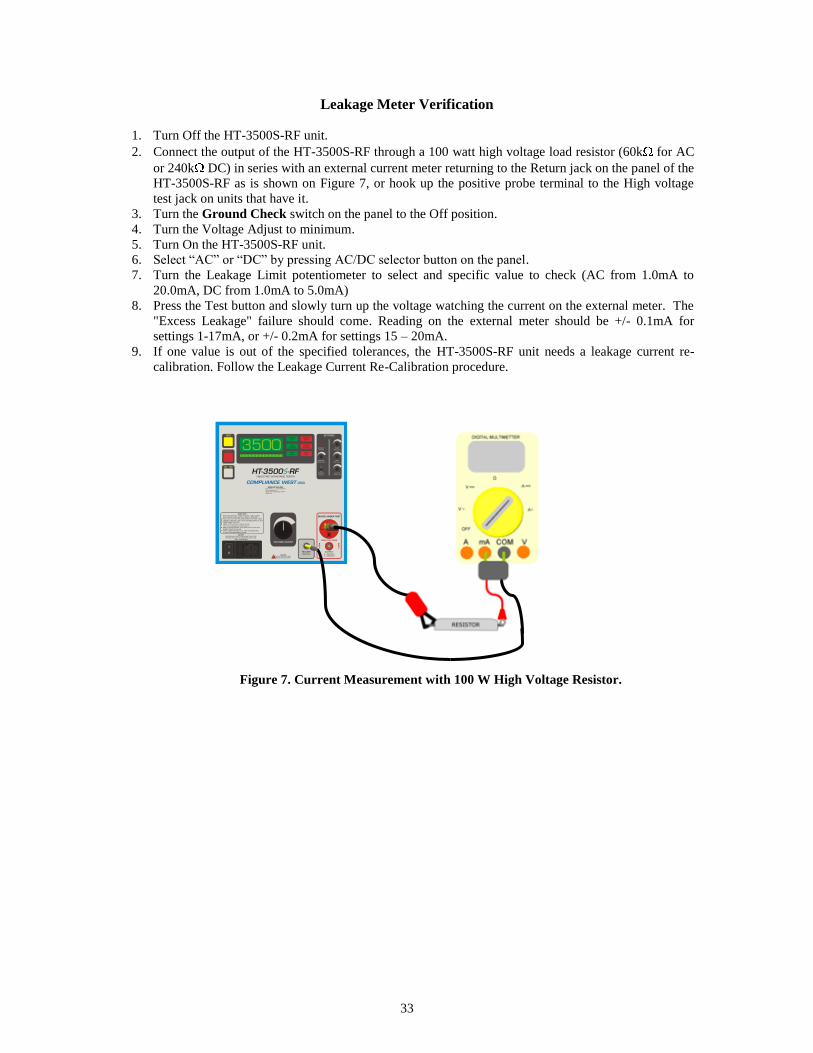
Leakage Meter Verification
1. Turn Off the HT-3500S-RF unit.
2. Connect the output of the HT-3500S-RF through a 100 watt high voltage load resistor (60k for AC
or 240k DC) in series with an external current meter returning to the Return jack on the panel of the
HT-3500S-RF as is shown on Figure 7, or hook up the positive probe terminal to the High voltage
test jack on units that have it.
3. Turn the Ground Check switch on the panel to the Off position.
4. Turn the Voltage Adjust to minimum.
5. Turn On the HT-3500S-RF unit.
6. Select “AC” or “DC” by pressing AC/DC selector button on the panel.
7. Turn the Leakage Limit potentiometer to select and specific value to check (AC from 1.0mA to
20.0mA, DC from 1.0mA to 5.0mA)
8. Press the Test button and slowly turn up the voltage watching the current on the external meter. The
"Excess Leakage" failure should come. Reading on the external meter should be +/- 0.1mA for
settings 1-17mA, or +/- 0.2mA for settings 15 – 20mA.
9. If one value is out of the specified tolerances, the HT-3500S-RF unit needs a leakage current re-
calibration. Follow the Leakage Current Re-Calibration procedure.
Figure 7. Current Measurement with 100 W High Voltage Resistor.

34
Leakage Current Re-Calibration
1. Turn Off the HT-3500S-RF unit.
2. Connect the output of the HT-3500S-RF through a 100 watt high voltage load resistor (60k for AC
or 240k DC) in series with an external current meter returning to the Return jack on the panel of the
HT-3500S-RF as is shown on Figure 7, or hook up the positive probe terminal to the High voltage
test jack on units that have it..
3. Enter to Calibration Mode. See Entering Calibration Mode procedure.
4. Select “AC” or “DC” by pressing AC/DC selector button on the panel.
5. Select the top calibration leakage point by pressing the Reset button until L1 is shown on the display
of the HT-3500S-RF unit.
6. Turn the Voltage Adjust on the panel to minimum (counterclockwise). Press the Test button and a
leakage number will be displayed on the panel meter (10.0 for AC or 5.0 for DC). Be careful as the
HT-3500S-RF will be putting out voltage at this point.
7. Slowly turn the Voltage Adjust on the panel clockwise until the current flowing on the external
current meter equals the number showed on the meter of the HT-3500S-RF unit, then, press the Test
button and the display will show “hold” for a few seconds, wait until the display show again "L1"
again.
8. Select the bottom calibration leakage point by pressing the Reset button until L2 is shown on the
display of the HT-3500S-RF unit.
9. Turn the Voltage Adjust on the panel to minimum (counterclockwise). Press the Test button and a
leakage number will be displayed on the panel meter. Be careful as the HT-3500S-RF will be putting
out voltage at this point.
10. Slowly turn the Voltage Adjust on the panel clockwise until the current flowing on the external
current meter equals the number showed on the meter of the HT-3500S-RF unit, then, press the Test
button and the display will show “hold” for a few seconds, wait until the display show again "L2"
again.
11. Turn Off the HT-3500S-RF tester.
12. Confirm the new leakage current calibration performing again the Leakage Current Verification
procedure, mentioned before.
35
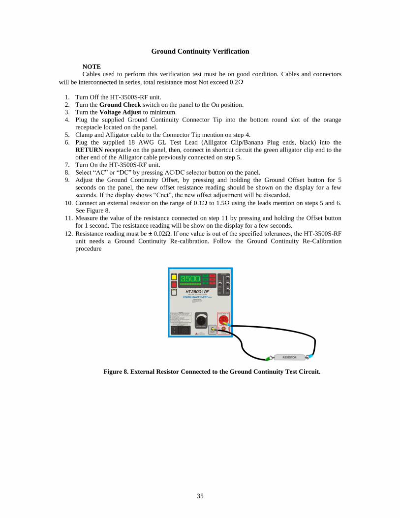
Ground Continuity Verification
NOTE
Cables used to perform this verification test must be on good condition. Cables and connectors
will be interconnected in series, total resistance most Not exceed 0.2
1. Turn Off the HT-3500S-RF unit.
2. Turn the Ground Check switch on the panel to the On position.
3. Turn the Voltage Adjust to minimum.
4. Plug the supplied Ground Continuity Connector Tip into the bottom round slot of the orange
receptacle located on the panel.
5. Clamp and Alligator cable to the Connector Tip mention on step 4.
6. Plug the supplied 18 AWG GL Test Lead (Alligator Clip/Banana Plug ends, black) into the
RETURN receptacle on the panel, then, connect in shortcut circuit the green alligator clip end to the
other end of the Alligator cable previously connected on step 5.
7. Turn On the HT-3500S-RF unit.
8. Select “AC” or “DC” by pressing AC/DC selector button on the panel.
9. Adjust the Ground Continuity Offset, by pressing and holding the Ground Offset button for 5
seconds on the panel, the new offset resistance reading should be shown on the display for a few
seconds. If the display shows “Cnct”, the new offset adjustment will be discarded.
10. Connect an external resistor on the range of 0.1 to 1.5 using the leads mention on steps 5 and 6.
See Figure 8.
11. Measure the value of the resistance connected on step 11 by pressing and holding the Offset button
for 1 second. The resistance reading will be show on the display for a few seconds.
12. Resistance reading must be 0.02Ω. If one value is out of the specified tolerances, the HT-3500S-RF
unit needs a Ground Continuity Re-calibration. Follow the Ground Continuity Re-Calibration
procedure
Figure 8. External Resistor Connected to the Ground Continuity Test Circuit.

36
Ground Continuity Re-Calibration
NOTE
Cables used to perform this test must be on excellent condition. Cables and connectors will be
interconnected in series, total resistance most Not exceed 0.02
WARNING
Dangerous voltages exist when energized. Exercise extreme care when working on an energized
circuit.
1. Turn Off the HT-3500S-RF unit.
2. Turn the Ground Check switch on the panel to the On position.
3. Turn the Voltage Adjust to minimum.
4. Disconnect the power cord from the of the HT-3500S-RF unit.
5. Internal calibration access. Remove the four side screws of the HT-3500S-RF unit, then, grasp the
top of the enclosure clamshell and lift it off the panel. Calibration adjustments of the Ground
Continuity are now accessible.
6. Enter to Calibration Mode. See Entering Calibration Mode procedure.
7. Select “AC” or “DC” by pressing AC/DC selector button on the panel.
8. Select the top calibration Ground Continuity point by pressing the Reset button until “r1” is shown
on the display of the HT-3500S-RF unit.
9. Connect an external resistor of 1.0 ( 1% tolerance), connect as it shown it in Figure 8.
10. Press the Test button one time, the meter will show 1.0, press the Test button again and wait until the
display return to “r1”.
11. Select the low calibration Ground Continuity point by pressing the Reset button until “r2” is shown
on the display of the HT-3500S-RF unit.
12. Connect an external resistor of 0.2 ( 1% tolerance or better), connect as it shown it in Figure 8.
13. Press the Test button one time, the meter will show 0.2, press the Test button again and wait until the
display return to “r2”.
14. Turn Off the HT-3500S-RF tester.
15. Confirm the new Ground Continuity calibration performing again the Ground Continuity
Verification procedure, mentioned before.