Embed Size (px)
Citation preview

5th International & 26th All India Manufacturing Technology, Design and Research Conference (AIMTDR 2014) December 12th–14th, 2014, IIT
Guwahati, Assam, India
104-1
HSS TOOL WEAR MECHANISM IN MACHINING OF HTBP BASED
COMPOSITE PROPELLANT GRAIN
Kishore Kumar Katikani1,VanapalliSrinivasaRohit 2,Anne Venu Gopal3*
and V.V. Rao4
1Scientist-D,NSTL,DRDO,Visakhapatnam-530027,Email: [email protected]
2 Research Scholar, NIT Warangal -506004, Email: [email protected] 3* Professor, NIT Warangal -506004, Email: [email protected]
4 Director,SPRITE,ASL,DRDO,Hyderabad -500058 Email:[email protected]
Abstract
Thrust characteristics of Solid propellant Rocket Motor (SRM) depend on the surface area of the propellant grain
exposed to initial ignition. For controlled combustion of propellant, contours and slots of initial ignition surface on
propellant grain are generated by turn milling operation. Metallic Aluminum powder is the fuel and Ammonium
Perchlorate (NH4ClO4) is the oxidizer in majority of HTPB (Hydroxyl Terminated Polybutadiene) based composite
propellants. Since the propellant being highly inflammable due to these sensitive ingredients, basic understanding of
machining process is very crucial for safety. The present paper focuses on the mechanism of tool wear of custom
made HSS inserts used in machining of propellant grain.
Eight cutting elements used in machining of propellant grain were examined to study the tool wear pattern and
predominant wear mechanism. Flank and rake surface were analyzed to determine the tool wear phenomena.
Microstructure of the machined surface of grain was determined to understand dispersion pattern of the ingredients
in composite propellant. K2 Chemical wear was found to be predominant. Understanding the wear mechanism helps
in development of improved insert or coatings on present insert in machining the solid propellant rocket motor. Keywords:HSS insert, Chemical wear, Propellant machining, and Solid rocket motors
1. Introduction
Understanding the science underlying machining of new
materials is an important aspect of metal cutting
research. HTPB(Hydroxyl Terminated Polybutadiene)
based solid propellant material has properties similar to
elastomers but is chemically reactive and highly
inflammable.Lewis. M.A has studied End milling of
elastomers using woodworking tools, along with
cryogenic cooling [1]. Use of induction heated tools at
low speed machining of elastomers has been studied by
Luo et al [2,3]. Use of cryogenic cooling and induction
heated tools is not possible options in this case due to
problem of rejection by contamination of propellant and
fire/explosion hazard due to heat sensitivity of
propellant respectively. Hence, a conventional
machining process using custom-made HSS inserts was
developed. The present paper focuses on establishing
tool wear mechanism for HSS inserts being used in
machining of Solid propellant Rocket Motor (SRM)
grain.
The thrust characteristics of a rocket motor depend
on the grain surface area exposed to initial ignition.
Generally solid propellant grains are vacuum casted
withAmmonium Perchlorate as oxidizer and metallic
Aluminium as fuel ingredients. The grain is casted with
central hole in a thermally insulated capsule supported
by metallic/composite casing and cured in oven to
achieve desired mechanical properties. The cured strand
of solid propellant material without casing is referred to
as propellant grain. To optimize the thrust
characteristics and to tailor the ballistic requirements,
the propellant grain is configured with secondary slots
in addition to precast central hole. These secondary slots
are remotely machined by CNC vertical turn milling
machine using custom build hollow side and face
milling cutter carrying HSS conical inserts, with
integrated safety systems to the machine.
2. Methods Experiments were conducted with a special purpose
CNC Vertical Turn Milling machine (Make: BECO,
Model: Special Purpose VTM-15kW) using a turbine
shaped cutter (Patent titled “A milling cutting tool”
bearing Application No.3023/DEL/2013,dated:10 Oct
2013) as shown in Figure 1. Custom made four conical
HSS TOOL WEAR MECHANISM IN MACHINING OF HTBP BASED COMPOSITE PROPELLANT GRAIN
104-2
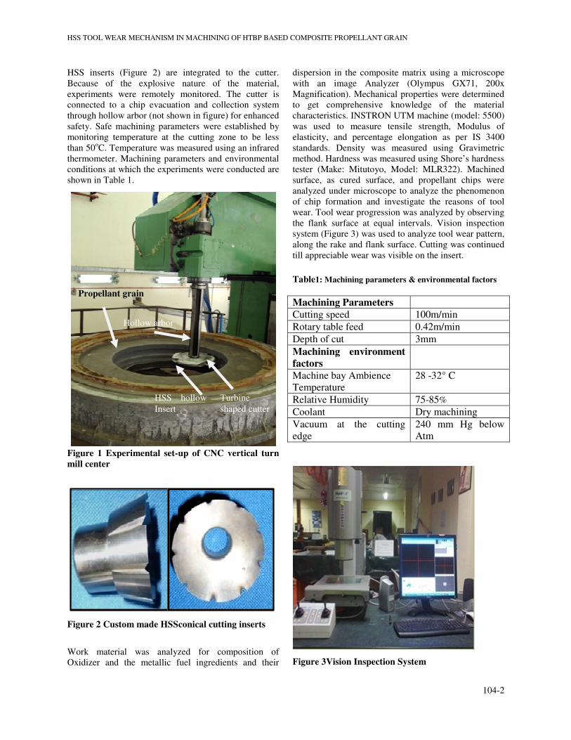
HSS inserts (Figure 2) are integrated to the cutter.
Because of the explosive nature of the material,
experiments were remotely monitored. The cutter is
connected to a chip evacuation and collection system
through hollow arbor (not shown in figure) for enhanced
safety. Safe machining parameters were established by
monitoring temperature at the cutting zone to be less
than 50oC. Temperature was measured using an infrared
thermometer. Machining parameters and environmental
conditions at which the experiments were conducted are
shown in Table 1.
Figure 1 Experimental set-up of CNC vertical turn
mill center
Figure 2 Custom made HSSconical cutting inserts
Work material was analyzed for composition of
Oxidizer and the metallic fuel ingredients and their
dispersion in the composite matrix using a microscope
with an image Analyzer (Olympus GX71, 200x
Magnification). Mechanical properties were determined
to get comprehensive knowledge of the material
characteristics. INSTRON UTM machine (model: 5500)
was used to measure tensile strength, Modulus of
elasticity, and percentage elongation as per IS 3400
standards. Density was measured using Gravimetric
method. Hardness was measured using Shore’s hardness
tester (Make: Mitutoyo, Model: MLR322). Machined
surface, as cured surface, and propellant chips were
analyzed under microscope to analyze the phenomenon
of chip formation and investigate the reasons of tool
wear. Tool wear progression was analyzed by observing
the flank surface at equal intervals. Vision inspection
system (Figure 3) was used to analyze tool wear pattern,
along the rake and flank surface. Cutting was continued
till appreciable wear was visible on the insert.
Table1: Machining parameters & environmental factors
Figure 3Vision Inspection System
Machining Parameters
Cutting speed 100m/min
Rotary table feed 0.42m/min
Depth of cut 3mm
Machining environment
factors
Machine bay Ambience
Temperature
28 -32° C
Relative Humidity 75-85%
Coolant Dry machining
Vacuum at the cutting
edge
240 mm Hg below
Atm
Propellant grain
HSS hollow
Insert
Hollow arbor
Turbine
shaped cutter

5th International & 26th All India Manufacturing Technology, Design and Research Conference (AIMTDR 2014) December 12th–14th, 2014, IIT
Guwahati, Assam, India
104-3
3. Results
3.1 Work material Phase/volume analysis The contents of the work piece in as cured condition are
found out using a microscope image with image
analyzer. Finding out volume fraction of the oxidizer,
fuel and other ingredients helps in analyzing the
possible reasons for tool wear. A sample image of the
analysis is shown in Figure 4. The average of three
samples was found out to be 67.86% of oxidizer (Table
2).Table 3 shows mechanical properties of the
propellant material.
Figure 4 Volume fraction analysis of work piece
material (a) Image from microscope (50x) (b) Image
analysis, pink showing Ammonium Perchlorate with
binder and green shows Aluminium (as cured
condition)
Table 2 Volume fractionof workpiece material
Table 3 Mechanical properties of propellant grain material
Tensile strength 600 kN/m2
Young's Modulus 4000 kN/m2
% elongation 30
Density 1.17–1.21×10³kg/m3
3.2 Analysis of Machined surface
Machined surface was compared with as cured surface
to get an idea of surface transformation. De-bonding of
Ammonium Perchlorate particles from the machined
surface was found (Figure 5(c)). The cross section of
chip was found to still have the particles intact as shown
in Figure 6(a).
Figure 5 (a) Unmachined (b) Machined surface (c) Voids
and debonded particles (Magnification 100x)
Figure 6 (a) chip cross section (b) Ammonium Perchlorate
(AP) particles collected along with the chip (Magnification
100x)
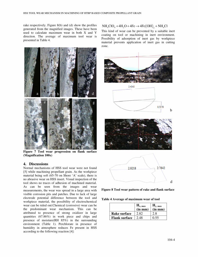
3.3 Tool wear
Figure 7 shows the progression of tool wear on flank
surface. Figure 7(a) shows formation of local corrosion
lines/dendrites. Figure 7(b) shows further dispersion by
growth of corrosion lines in the contact area close to the
cutting edge. Figure 7(c) shows formation of corrosion
pits from the corrosion lines. The tool surface can be
seen to have eroded unevenly. Figure 7(d) shows
joining of local corrosion lines and corrosion pits into
corrosion/pitting patch. Figure 7(e) shows deepening of
corrosion patches. Figure 7(f) shows growth of pitting
patches into large pitting volumes. Figure 7(g) shows
the final worn out area of tool by corrosion action.
3.4 Analysis of Tool wear pattern using Visual
Inspection system
Tools were inspected after their end of life to measure
flank and its wear pattern. The wear pattern observed
under system is converted into a CAD drawing that can
be used to find wear area and also maximum wear in
horizontal and vertical direction (Figure 8). Figure 8(a)
and (c) show the magnified images of the tool flank and
Sample
No
Ammonium
Perchlorate
(ρ=1.95)
Binder &
metallic
fuel (ρ=2.4)
1 71.51 28.49
2 67.21 32.79
3 64.86 35.14
Average 67.86 32.14
Coarse AP
particles
fine AP
particles
a b
Embeded AP
under binder
void
De-bonded
AP particles
Void
a b
c
a b
HSS TOOL WEAR MECHANISM IN MACHINING OF HTBP BASED COMPOSITE PROPELLANT GRAIN
104-4
rake respectively. Figure 8(b) and (d) show the profiles
generated from the magnified images. These have been
used to calculate maximum wear in both X and Y
direction. The average of maximum tool wear is
presented in Table 4.
Figure 7 Tool wear progression on flank surface
(Magnification 100x)
4. Discussions Normal mechanisms of HSS tool wear were not found
[5] while machining propellant grain. As the workpiece
material being soft (65-70 on Shore ‘A’ scale), there is
no abrasive wear on HSS insert. Visual inspection of the
tool shows no traces of adhesion of machined material.
As can be seen from the images and wear
measurements, the wear was spread in a large area with
visible corrosion pits and patches. Due to lack of large
electrode potential difference between the tool and
workpiece material, the possibility of electrochemical
wear can be ruled out.Chemical (corrosive) wear can be
the predominant wear mechanism. This can be
attributed to presence of strong oxidizer in large
quantities (67.86%) in work piece and chips and
presence of moisture(RH 85%) in the surrounding
environment (Table 1). Perchlorate in presence of
humidity in atmosphere reduces Fe present in HSS
according to the following reaction [4]:
( )4 4 2 42NH ClO 4H O 4Fe 4Fe OH NH Cl+ + → +
This kind of wear can be prevented by a suitable inert
coating on tool or machining in inert environment.
Possibility of adsorption of inert gas by workpiece
material prevents application of inert gas in cutting
zone.
Figure 8 Tool wear pattern of rake and flank surface
Table 4 Average of maximum wear of tool
Hx, max
(in mm)
Hy, max
(in mm)
Rake surface 2.82 2.8
Flank surface 2.48 0.55
a
b
d
c
a b c d
g f e

5th International & 26th All India Manufacturing Technology, Design and Research Conference (AIMTDR 2014) December 12th–14th, 2014, IIT
Guwahati, Assam, India
104-5
5. Conclusions The predominant wear in HSS insert of turbine cutter
while machining of HTPB based composite propellant
grain with AP as oxidizer is Chemical wear. The pitting
corrosion on rake and flank face of the HSS insert
confirms the same. This wear is further accelerated in
presence of high RH values at the cutting zone and
application of air stream as vacuum near cutting edge.
The knowledge of possible tool wear mechanism
enables in designing a suitable inert coating for the tool
and in selection of new tool materials. The method used
to measure wear pattern provides an easier method to
determine various parameters of flank and crater wear,
including crater depth up to some extent.
6. Acknowledgements The authors express their sincere thanks The General
Manager, DRDO, Jagdalpur and Director, NSTL for the
support of facility extended and equipments.
7. References 1. Lewis, M. A. (2002). End milling of
elastomers.(Doctoral dissertation, NC State
University)
2. Luo, J. (2005). Machining of Elastomers (Doctoral
dissertation, The University of Michigan).
3. Luo, J., Ding, H., & Shih, A. J. (2005). Induction-
Heated Tool Machining of Elastomers—Part 2:
Chip Morphology, Cutting Forces, and Machined
Surfaces. Machining science and technology, 9(4),
567-588.
4. Prinz, H., &Strehblow, H. H. (1998). Investigations
on pitting corrosion of iron in perchlorate
electrolytes. Corrosion science, 40(10), 1671-1683.
5. Trent, E. M., & Wright, P. K. (2000). Metal cutting.
Butterworth-Heinemann.


![Effect of Coolant Temperature on Machining Characteristics ... · machining. Machining with coolant will help to reduce wear, corrosion and creep of the materials [28-30]. Although,](https://img.dokumen.tips/doc/110x75/5e94a747103e90191c2608ba/effect-of-coolant-temperature-on-machining-characteristics-machining-machining.jpg)