Embed Size (px)
Citation preview
http://www.iaeme.com/IJMET/index.asp 120 [email protected]
International Journal of Mechanical Engineering and Technology (IJMET) Volume 8, Issue 1, January 2017, pp. 120–131, Article ID: IJMET_08_01_013
Available online at http://www.iaeme.com/IJMET/issues.asp?JType=IJMET&VType=8&IType=1
ISSN Print: 0976-6340 and ISSN Online: 0976-6359
© IAEME Publication
ENHANCING THE MACHINING PERFORMANCE OF
HSS DRILL IN THE DRILLING OF GFRP COMPOSITE
BY REDUCING TOOL WEAR THROUGH WEAR
MECHANISM MAPPING
Dr. U. Sathish Rao
Department of Mechanical and Manufacturing Engineering, Manipal Institute of Technology,
Manipal University, Manipal, India
Dr. Lewlyn L.R. Rodrigues
Department of Humanities and Management, Manipal Institute of Technology,
Manipal University, Manipal, India
ABSTRACT
The wear characteristics of cutting tools is affected by the machining factors such as the
magnitude of the cutting speed, extent of the cutting tool movements in the feed direction, the
geometry of the cutting tool etc. This research paper presents some original research into the wear
types, as well as the phenomena that occurs in the cutting tool/work material interface zone and
their relationships to cause different wear mechanisms (adhesion, abrasion and diffusion) in hole
machining process. A wear mechanism map involving the tool wear characteristics of uncoated
High Speed Steel (HSS) drill of 6mm diameter is constructed for the drilling of Glass Fiber
Reinforced Polyester (GFRP) composite laminates. Different wear modes observed and identified
by the surface micrograph image of land / flank of uncoated HSS drillsto describe a number of
wear mechanisms. The dominant wear mechanisms include adhesive wear, adhesive and abrasive
wear, abrasive wear and fatigue / thermal wear. In the wear mechanism map, a wear region was
identified, which is called “safety cutting zone” or “mild wear zone”, where the minimum flank
wear of the HSS drill tool occurs. In order to carry out the drilling operation on the GFRP
composite in the “safety cutting zone” or “mild wear zone”, it was found that the spindle speed
should be set in the range of 1200-1590 rpm and feed rate must be set to 0.10 – 0.16 mm/rev. Thus,
the wear mechanism map constructed here can be used as a reference for selecting suitable drilling
parameters of uncoated HSS drill tools for GFRP composites.
Key words: GFRP composites, drilling, wear mechanism map, wear mechanism, HSS drill, safety
cutting zone
Cite this Article: Dr. U. Sathish Rao and Dr. Lewlyn L.R. Rodrigues. Enhancing the Machining
Performance of HSS Drill in the Drilling of GFRP Composite by Reducing Tool Wear through
Wear Mechanism. International Journal of Mechanical Engineering and Technology, 8(1), 2017,
pp. 120–131.
http://www.iaeme.com/IJMET/issues.asp?JType=IJMET&VType=8&IType=1
Enhancing the Machining Performance of HSS Drill in the Drilling of GFRP Composite by Reducing
Tool Wear through Wear Mechanism
http://www.iaeme.com/IJMET/index.asp 121 [email protected]
1. INTRODUCTION
Machining using the cutting tool is the collective process of friction and wear at the tool work interface
zone. During machining, the cutting tool undergoes tool wear that reduces the life of the cutting tool,
reduces the productivity but increases the surface roughness of the machined work pieces. In recent days,
Polymer Matrix Composites have found wide range of applications starting from household appliances up
to the extent of automobile and aircraft components. Drilling is one of the most essential machining
operation used for polymer matrix composites in assembly operation using fasteners [1-3]. Because of the
discovery of more effective and efficient automobile/aircraft components and their corresponding
materials, along the addition of modern CNC machines for machining, the manufacturer’s prerequisite is to
increase the life of cutting tools during the machining process in order to increase the machining efficiency
and to lower the manufacturing/production cost. However, the study on the wear rates and wear
mechanisms of cutting tools in drilling of polymer matrix composites are very limited and are still not
enough to meet the industrial requirements of manufacturing and machining [2]. Therefore the wear rate
map and wear transition / mechanism map pertaining to a specific cutting tool / work piece pair becomes
prominent for selecting the appropriate machining parameters since the whole wear rate map and wear
mechanism maps areplotted under various machining process conditions and machining parameters.
In later 80’s, Lim and Ashby constructed the first wear mechanism map in the tribology field [4,5],
which combined theoretical and practical works together. In the early 90’s, a wear mechanism map of
aluminum alloys was constructed by Liu [6,7]. After systematic studies on the wear process of cutting
tools, Lim, Liu and coworkers constructed few wear maps of tools cutting steels, which used feed rates and
cutting speeds as two axis respectively [8,9,10]. These maps explained the tribological characteristics of
HSS tool while machining steels and relative wear mechanisms in different regions under dry running
conditions.
Drilling is an important machining of the polymer composite material, so the wear mechanism map of
drilled tools was studied in this paper. Also, in this research, the wear mechanism map of uncoated HSS
tools during dry-drilling of the polymer composite material is constructed, and the safety zone is identified
in which the wear rate of tools would be minimum [15]. It is also possible to use the wear mechanism
maps for other form of machining, to predict the general trend of tool wear, such as the approximate
location of the lower-wear regions [11].
These maps will also be treated as good references for choosing suitable processing parameters for
uncoated HSS tools drilling of GFRP composites. These maps describe the tribological features of HSS
tool drilling GFRP composite and relative wear mechanisms in different regions under dry machining
conditions [15]. In this research the wear mechanism map of uncoated HSS tools drilling GFRP composite
laminates is constructed by considering drilling process parameters at different levels. The work piece
material (GFRP composite laminate of thickness 10mm), tool material (uncoated HSS drill), tool diameter
(6 mm) are fixed under dry drilling machining condition. The drilling operation is carried out on the CNC
vertical machining center, and thus the data collected to construct the wear map are more reliable. In the
end, the wear map for HSS tools drilling GFRP composite will be related to practical machining conditions
to optimize machining parameters. These maps can become a good reference for choosing process
parameters of uncoated HSS drills in the machining of GFRP composites.
Dr. U. Sathish Rao and Dr. Lewlyn L.R. Rodrigues
http://www.iaeme.com/IJMET/index.asp 122 [email protected]
2. MATERIALS AND METHODS
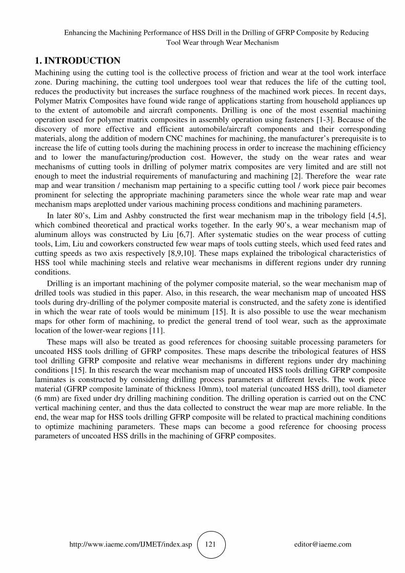
2.1. GFRP Material Fabrication
Figure 1 Schematic of hand lay-up technique Figure 2 Schematic of hand lay-up technique
Table 1 GFRP composite specifications
The GFRP composite laminate was fabricated to a fiber weight fraction of 33% by mixing
approximately 2 kilogram of Isophthalic polyester resin with 1 kg of randomly oriented structural glass
reinforcement and the hardener (Poly Ether Ether Ketone). Laminate sample with dimension of
600×600×10 mm was fabricated using hand lay-up process (Figure 1). The laminate was hardened under
atmospheric temperature and pressure conditions for a period of 24 hours. The properties of the GFRP
composite are listed in Table 1. The GFRP composite laminate after the fabrication and atmospheric curing
is shown in Figure 2.
Table 2 Drill Tool dimension specifications
Matrix Material Isophthalic Polyester resin
Fiber S-glass fiber
Fiber diameter 15 microns
Fabric type Stitched mat type
Fiber orientation Random
Fiber weight fraction 33%
Material density 1.6 g/mm3
Laminate thickness 10 mm
Tool Material High Speed Steel
Tool diameter 8 mm
No. of Flutes 2
Point angle 118º
Helix angle 30º
Flute length 77 mm
Shank type Cylindrical
Enhancing the Machining Performance of HSS Drill in the Drilling of GFRP Composite by Reducing
Tool Wear through Wear Mechanism
http://www.iaeme.com/IJMET/index.asp 123 [email protected]
The wear mechanism / transition map of uncoated HSS drills of 8mm diameter, machining GFRP
composite laminates is constructed through the wear data collection. The wear data is collected through
experimental work, carried out by considering drilling process parameters at different levels. The GFRP
laminate is manufactured for a constant thickness of 10mm and is used for machining operation. Bosch
manufactured uncoated HSS drills of 6 mm diameter (refer Table 2 for specifications) was used for drilling
in dry run condition.
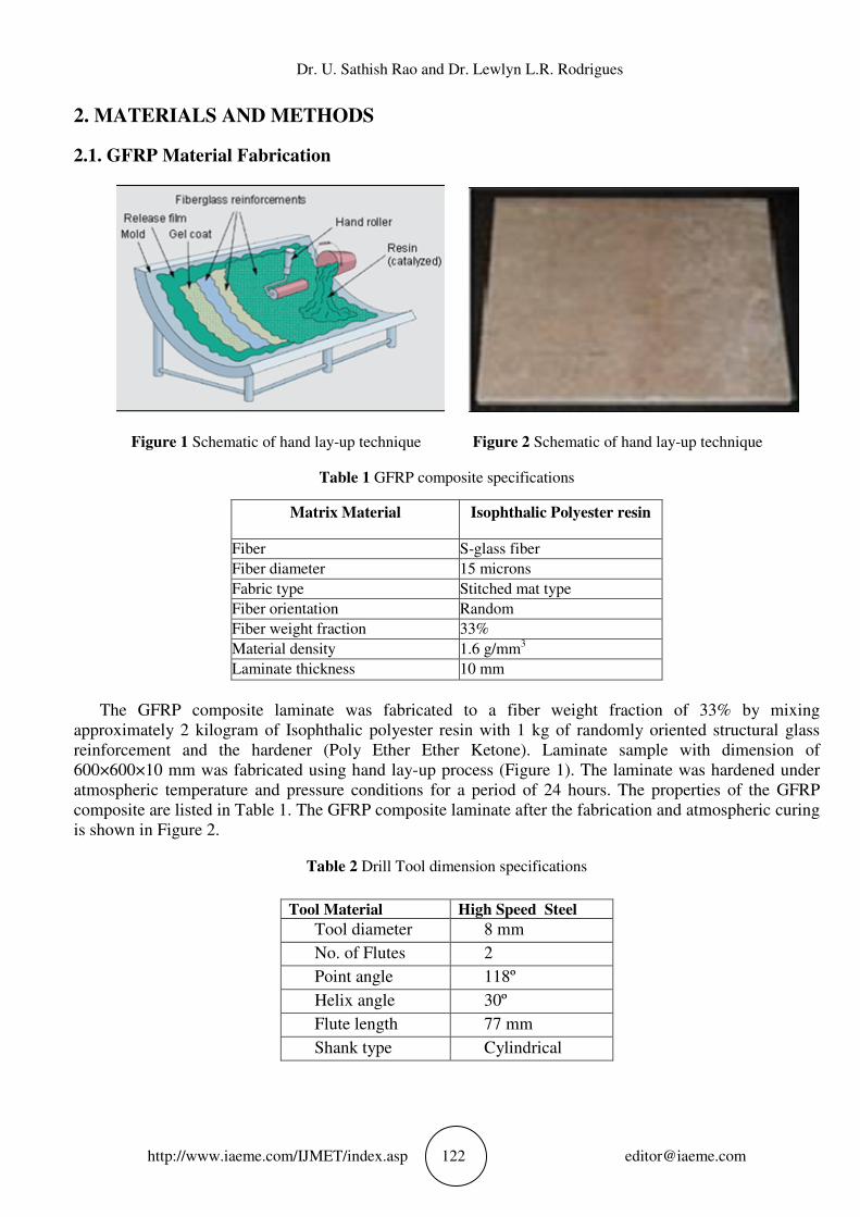
In order to maintain accuracy and data reliability, the drilling operation on the GFRP composite was
carried out on Computer Numerical Controlled (CNC) Vertical Machining Center (VMC) (Figure 3).
During machining, 80 holes of 6 mm diameter were drilled on the GFRP composite laminate using
uncoated HSS twist drill (Figure 4). The drilled holes are spaced on the composite laminate as per the drill
hole specifications and standards for fasteners. The spindle speed varied from 1200 rpm(cutting speed =
22.62 m/min) to 1800 rpm (cutting speed = 33.93 m/min) while the feed rate is varied from 0.1 mm/rev to
0.3 mm/rev as shown in Table 3. Each experimental run was designed with different parameters by
applying the Design of Experiments (DoE) concept as shown in Table 1.
Figure 3 VMC performing drilling on composite laminate Figure 4 HSS drills of diameter 6, 8 and 10mm
Before and after drilling the holes, the HSS drills were cleaned with Acetone and NaOH solution to
remove the impurities. A fresh HSS drill was used for each experimental run and two replications of each
run was carried out and the average of the resultant was computed for wear data collection. In the present
research, the tool wear rate was measured by applying the weight difference method. A digital weighing
machine with an accuracy of 0.0001g was used for the weighing purpose. The average of, weight
difference of two replication of each experimental run is calculated and considered for analysis and for
plotting wear rate maps. The wear data along with the study of micrograph images are used for plotting the
wear maps. To get a dimensionless wear rate value, the value of the wear rate measured was normalized
[12,13].
The drill cutting speed and feed rate were employed as abscissa and ordinate during wear rate and wear
mechanism map plotting. The wear maps were plotted by normalizing wear data on a log scale so as to get
the dimensionless wear rate. The following equations [14] were used for this purpose.
Normalised wear rate = Wn= W/An; where W= wear rate and An = Nominal contact area
W = wear rate = Mass lost in time / Density (mm3min
-1)
Mass loss = Massbefore – Massafter / Time (g/min)
Dr. U. Sathish Rao and Dr. Lewlyn L.R. Rodrigues
http://www.iaeme.com/IJMET/index.asp 124 [email protected]
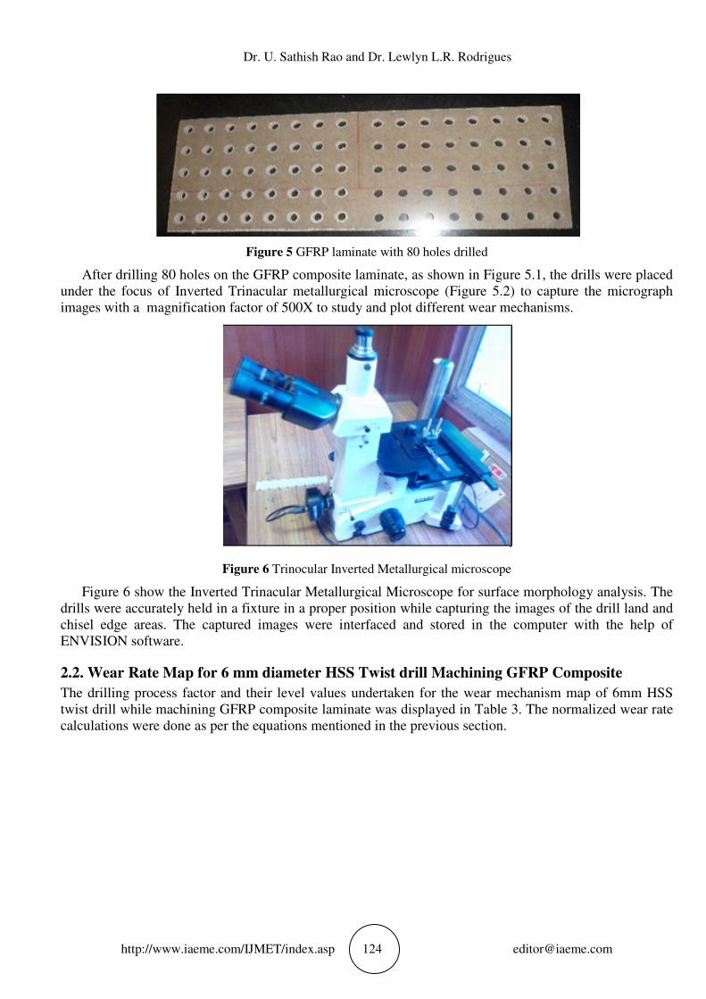
Figure 5 GFRP laminate with 80 holes drilled
After drilling 80 holes on the GFRP composite laminate, as shown in Figure 5.1, the drills were placed
under the focus of Inverted Trinacular metallurgical microscope (Figure 5.2) to capture the micrograph
images with a magnification factor of 500X to study and plot different wear mechanisms.
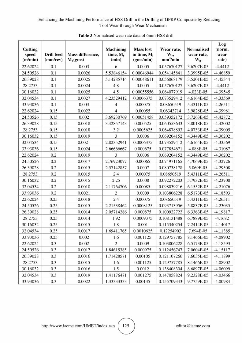
Figure 6 Trinocular Inverted Metallurgical microscope
Figure 6 show the Inverted Trinacular Metallurgical Microscope for surface morphology analysis. The
drills were accurately held in a fixture in a proper position while capturing the images of the drill land and
chisel edge areas. The captured images were interfaced and stored in the computer with the help of
ENVISION software.
2.2. Wear Rate Map for 6 mm diameter HSS Twist drill Machining GFRP Composite
The drilling process factor and their level values undertaken for the wear mechanism map of 6mm HSS
twist drill while machining GFRP composite laminate was displayed in Table 3. The normalized wear rate
calculations were done as per the equations mentioned in the previous section.
Enhancing the Machining Performance of HSS Drill in the Drilling of GFRP Composite by Reducing
Tool Wear through Wear Mechanism
http://www.iaeme.com/IJMET/index.asp 125 [email protected]
Table 3 Normalised wear rate data of 6mm HSS drill
Cutting
speed
(m/min)
Drill feed
(mm/rev)
Mass difference,
Md(gms)
Machining
time, Mt
(min)
Mass lost
in time, Ml
(gms/min)
Wear rate,
Wr,
mm3/min
Normalised
wear rate,
Wn
Log
(norm.
wear
rate)
22.62024 0.1 0.003 6 0.0005 0.057670127 3.6207E-05 -4.4412
24.50526 0.1 0.0026 5.53846154 0.00046944 0.054145841 3.3995E-05 -4.46859
26.39028 0.1 0.0025 5.14285714 0.00048611 0.056068179 3.5201E-05 -4.45344
28.2753 0.1 0.0024 4.8 0.0005 0.057670127 3.6207E-05 -4.4412
30.16032 0.1 0.0025 4.5 0.00055556 0.064077919 4.023E-05 -4.39545
32.04534 0.1 0.0027 4.23529412 0.0006375 0.073529412 4.6164E-05 -4.33569
33.93036 0.1 0.003 4 0.00075 0.08650519 5.4311E-05 -4.26511
22.62024 0.15 0.0022 4 0.00055 0.06343714 3.9828E-05 -4.39981
24.50526 0.15 0.002 3.69230769 0.00051458 0.059352172 3.7263E-05 -4.42872
26.39028 0.15 0.0018 3.42857143 0.000525 0.060553633 3.8018E-05 -4.42002
28.2753 0.15 0.0018 3.2 0.0005625 0.064878893 4.0733E-05 -4.39005
30.16032 0.15 0.0019 3 0.0006 0.069204152 4.3449E-05 -4.36202
32.04534 0.15 0.0021 2.82352941 0.0006375 0.073529412 4.6164E-05 -4.33569
33.93036 0.15 0.0024 2.66666667 0.000675 0.077854671 4.888E-05 -4.31087
22.62024 0.2 0.0019 3 0.0006 0.069204152 4.3449E-05 -4.36202
24.50526 0.2 0.0017 2.76923077 0.00065 0.074971165 4.7069E-05 -4.32726
26.39028 0.2 0.0015 2.57142857 0.0007 0.080738178 5.069E-05 -4.29508
28.2753 0.2 0.0015 2.4 0.00075 0.08650519 5.4311E-05 -4.26511
30.16032 0.2 0.0015 2.25 0.0008 0.092272203 5.7932E-05 -4.23708
32.04534 0.2 0.0018 2.11764706 0.00085 0.098039216 6.1552E-05 -4.21076
33.93036 0.2 0.0021 2 0.0009 0.103806228 6.5173E-05 -4.18593
22.62024 0.25 0.0018 2.4 0.00075 0.08650519 5.4311E-05 -4.26511
24.50526 0.25 0.0015 2.21538462 0.0008125 0.093713956 5.8837E-05 -4.23035
26.39028 0.25 0.0014 2.05714286 0.000875 0.100922722 6.3363E-05 -4.19817
28.2753 0.25 0.0014 1.92 0.0009375 0.108131488 6.7889E-05 -4.1682
30.16032 0.25 0.0015 1.8 0.001 0.115340254 7.2414E-05 -4.14017
32.04534 0.25 0.0017 1.69411765 0.0010625 0.12254902 7.694E-05 -4.11385
33.93036 0.25 0.002 1.6 0.001125 0.129757785 8.1466E-05 -4.08902
22.62024 0.3 0.002 2 0.0009 0.103806228 6.5173E-05 -4.18593
24.50526 0.3 0.0017 1.84615385 0.000975 0.112456747 7.0604E-05 -4.15117
26.39028 0.3 0.0016 1.71428571 0.00105 0.121107266 7.6035E-05 -4.11899
28.2753 0.3 0.0015 1.6 0.001125 0.129757785 8.1466E-05 -4.08902
30.16032 0.3 0.0016 1.5 0.0012 0.138408304 8.6897E-05 -4.06099
32.04534 0.3 0.0019 1.41176471 0.001275 0.147058824 9.2328E-05 -4.03466
33.93036 0.3 0.0022 1.33333333 0.00135 0.155709343 9.7759E-05 -4.00984
Dr. U. Sathish Rao and Dr. Lewlyn L.R. Rodrigues
http://www.iaeme.com/IJMET/index.asp 126 [email protected]
3. METHODOLOGY OF WEAR MAPPING
The following steps are involved in the construction of wear rate / mechanism maps in the present research
work.
• For the pair of materials considered in this research work i.e., Glass Fiber Reinforced Polymer (GFRP)
composite and HSS drill bits, their contact mode (unidirectional through hole drilling), their contact
geometry (surface contact), the working environment condition in which the pair of materials are to interact
(CNC drilling) and lubrication condition (dry run) is decided before starting the experiment.
• Experimental wear data was gathered from the in-house drilling experiments carried out on the CNC-
Vertical Machining Center. Mathematical models describing wear behavior of this pair should be gathered
through the literature review.
• The process parameters to be used as the two axes of the wear map and also their range to be included on the
wear maps is decided.
• According to the mode and mechanism of wear, the wear data are grouped. The wear-rate / wear transition /
wear-mechanism data, appropriately classified, are then plotted on the two-dimensional axes defining the
map. Each mechanism is then separated using boundaries and the approximate locations of the contours of
constant wear rate. At this stage, the wear map is sufficiently informative showing different wear
mechanisms on the wear rate map.
• The final step is to identify the “safety zone” or “safe working region” “low wear zone” where the overall /
total drill tool wear is going to be minimum. This zone gives the optimum range of process parameters that
could minimize the tool wear, indirectly enhancing the operational performance, tool life of the drill tool and
ending with increased productivity
For the present research work, the spindle speed and the feed rate were chosen as two axes required for
constructing the two dimensional wear map of HSS tools drilling GFRP composites. The wear rate maps
were drawn by normalizing the wear rate values against spindle speed and feed rate. Wear maps were built
by taking cutting speed (rpm)as abscissa, and the feed rate (mm/rev) as the ordinate.
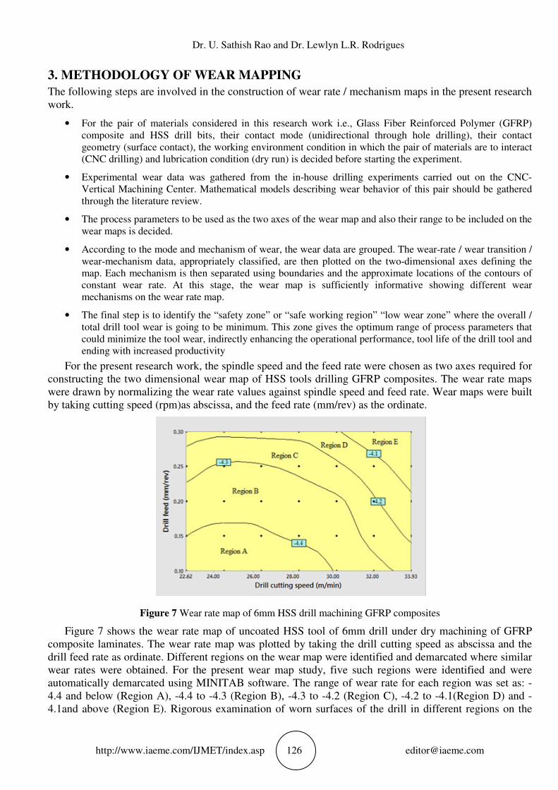
Figure 7 Wear rate map of 6mm HSS drill machining GFRP composites
Figure 7 shows the wear rate map of uncoated HSS tool of 6mm drill under dry machining of GFRP
composite laminates. The wear rate map was plotted by taking the drill cutting speed as abscissa and the
drill feed rate as ordinate. Different regions on the wear map were identified and demarcated where similar
wear rates were obtained. For the present wear map study, five such regions were identified and were
automatically demarcated using MINITAB software. The range of wear rate for each region was set as: -
4.4 and below (Region A), -4.4 to -4.3 (Region B), -4.3 to -4.2 (Region C), -4.2 to -4.1(Region D) and -
4.1and above (Region E). Rigorous examination of worn surfaces of the drill in different regions on the
Enhancing the Machining Performance of HSS Drill in the Drilling of GFRP Composite by Reducing
Tool Wear through Wear Mechanism
http://www.iaeme.com/IJMET/index.asp 127 [email protected]
wear rate map was done to identify the HSS drill wear mechanisms. The micrograph observations of the
worn surfaces of drill land, chisel edge and flank area were taken with a magnification factor 500X for the
microanalysis. The wear mechanisms were decided after examining a number of micrograph images with
respect to each of the region and by considering the best among them.
3.1. Results and Discussion on Micrograph Analysis (drill diameter=6mm)
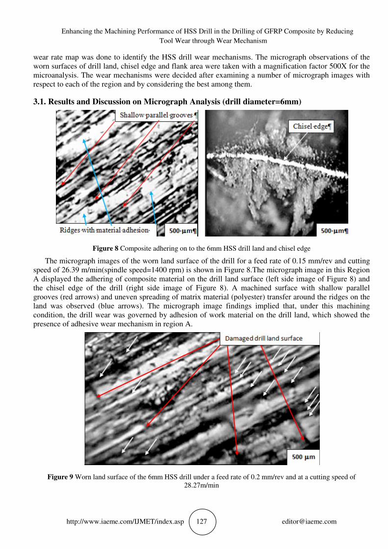
Figure 8 Composite adhering on to the 6mm HSS drill land and chisel edge
The micrograph images of the worn land surface of the drill for a feed rate of 0.15 mm/rev and cutting
speed of 26.39 m/min(spindle speed=1400 rpm) is shown in Figure 8.The micrograph image in this Region
A displayed the adhering of composite material on the drill land surface (left side image of Figure 8) and
the chisel edge of the drill (right side image of Figure 8). A machined surface with shallow parallel
grooves (red arrows) and uneven spreading of matrix material (polyester) transfer around the ridges on the
land was observed (blue arrows). The micrograph image findings implied that, under this machining
condition, the drill wear was governed by adhesion of work material on the drill land, which showed the
presence of adhesive wear mechanism in region A.
Figure 9 Worn land surface of the 6mm HSS drill under a feed rate of 0.2 mm/rev and at a cutting speed of
28.27m/min
Dr. U. Sathish Rao and Dr. Lewlyn L.R. Rodrigues
http://www.iaeme.com/IJMET/index.asp 128 [email protected]
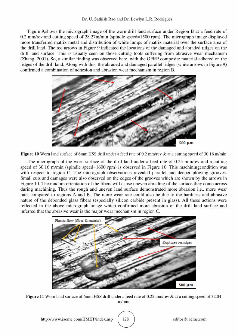
Figure 9,shows the micrograph image of the worn drill land surface under Region B at a feed rate of
0.2 mm/rev and cutting speed of 28.27m/min (spindle speed=1500 rpm). The micrograph image displayed
more transferred matrix metal and distribution of white lumps of matrix material over the surface area of
the drill land. The red arrows in Figure 9 indicated the locations of the damaged and abraded ridges on the
drill land surface. This is usually seen on those cutting tools suffering from abrasive wear mechanism
(Zhang, 2001). So, a similar finding was observed here, with the GFRP composite material adhered on the
ridges of the drill land. Along with this, the abraded and damaged parallel ridges (white arrows in Figure 9)
confirmed a combination of adhesion and abrasion wear mechanism in region B.
Figure 10 Worn land surface of 6mm HSS drill under a feed rate of 0.2 mm/rev & at a cutting speed of 30.16 m/min
The micrograph of the worn surface of the drill land under a feed rate of 0.25 mm/rev and a cutting
speed of 30.16 m/min (spindle speed=1600 rpm) is observed in Figure 10. This machiningcondition was
with respect to region C. The micrograph observations revealed parallel and deeper plowing grooves.
Small cuts and damages were also observed on the edges of the grooves which are shown by the arrows in
Figure 10. The random orientation of the fibers will cause uneven abrading of the surface they come across
during machining. Thus the rough and uneven land surface demonstrated more abrasion i.e., more wear
rate, compared to regions A and B. The more wear rate could also be due to the hardness and abrasive
nature of the debonded glass fibers (especially silicon carbide present in glass). All these actions were
reflected in the above micrograph image which confirmed more abrasion of the drill land surface and
inferred that the abrasive wear is the major wear mechanism in region C.
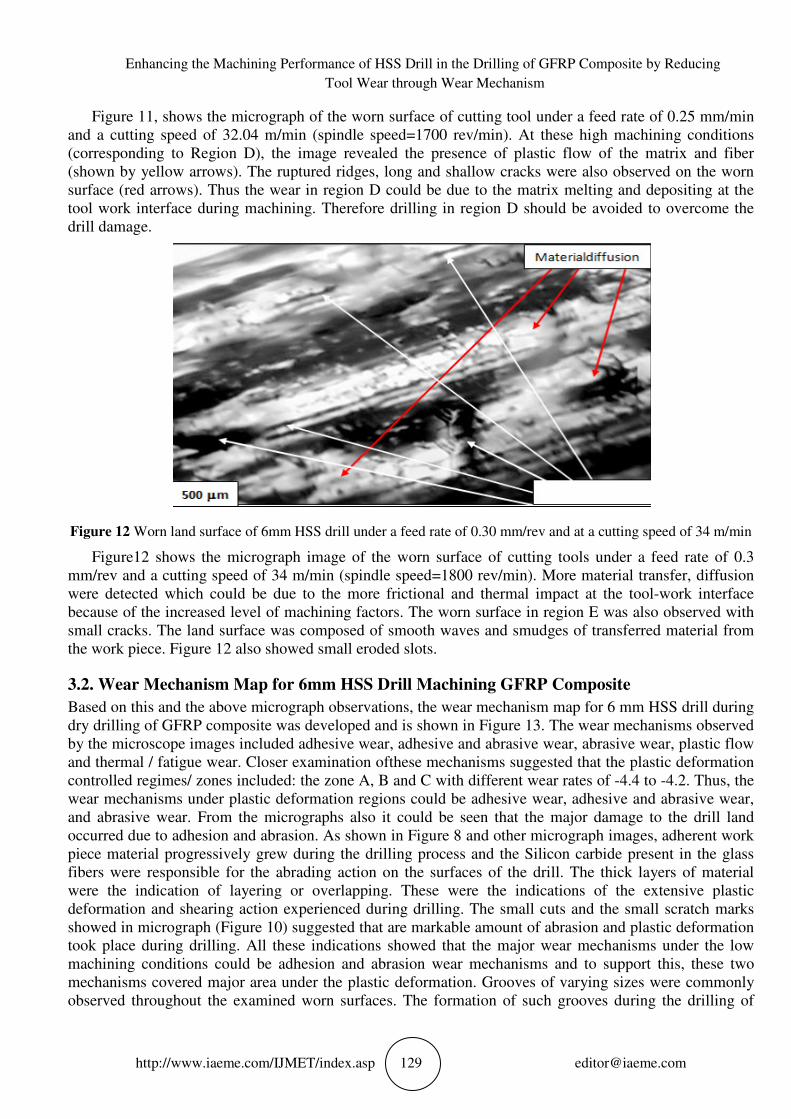
Figure 11 Worn land surface of 6mm HSS drill under a feed rate of 0.25 mm/rev & at a cutting speed of 32.04
m/min
Enhancing the Machining Performance of HSS Drill in the Drilling of GFRP Composite by Reducing
Tool Wear through Wear Mechanism
http://www.iaeme.com/IJMET/index.asp 129 [email protected]
Figure 11, shows the micrograph of the worn surface of cutting tool under a feed rate of 0.25 mm/min
and a cutting speed of 32.04 m/min (spindle speed=1700 rev/min). At these high machining conditions
(corresponding to Region D), the image revealed the presence of plastic flow of the matrix and fiber
(shown by yellow arrows). The ruptured ridges, long and shallow cracks were also observed on the worn
surface (red arrows). Thus the wear in region D could be due to the matrix melting and depositing at the
tool work interface during machining. Therefore drilling in region D should be avoided to overcome the
drill damage.
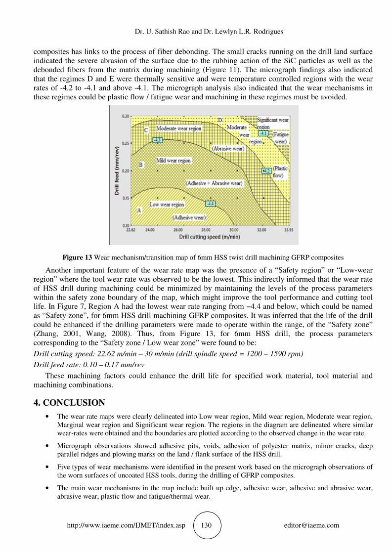
Figure 12 Worn land surface of 6mm HSS drill under a feed rate of 0.30 mm/rev and at a cutting speed of 34 m/min
Figure12 shows the micrograph image of the worn surface of cutting tools under a feed rate of 0.3
mm/rev and a cutting speed of 34 m/min (spindle speed=1800 rev/min). More material transfer, diffusion
were detected which could be due to the more frictional and thermal impact at the tool-work interface
because of the increased level of machining factors. The worn surface in region E was also observed with
small cracks. The land surface was composed of smooth waves and smudges of transferred material from
the work piece. Figure 12 also showed small eroded slots.
3.2. Wear Mechanism Map for 6mm HSS Drill Machining GFRP Composite
Based on this and the above micrograph observations, the wear mechanism map for 6 mm HSS drill during
dry drilling of GFRP composite was developed and is shown in Figure 13. The wear mechanisms observed
by the microscope images included adhesive wear, adhesive and abrasive wear, abrasive wear, plastic flow
and thermal / fatigue wear. Closer examination ofthese mechanisms suggested that the plastic deformation
controlled regimes/ zones included: the zone A, B and C with different wear rates of -4.4 to -4.2. Thus, the
wear mechanisms under plastic deformation regions could be adhesive wear, adhesive and abrasive wear,
and abrasive wear. From the micrographs also it could be seen that the major damage to the drill land
occurred due to adhesion and abrasion. As shown in Figure 8 and other micrograph images, adherent work
piece material progressively grew during the drilling process and the Silicon carbide present in the glass
fibers were responsible for the abrading action on the surfaces of the drill. The thick layers of material
were the indication of layering or overlapping. These were the indications of the extensive plastic
deformation and shearing action experienced during drilling. The small cuts and the small scratch marks
showed in micrograph (Figure 10) suggested that are markable amount of abrasion and plastic deformation
took place during drilling. All these indications showed that the major wear mechanisms under the low
machining conditions could be adhesion and abrasion wear mechanisms and to support this, these two
mechanisms covered major area under the plastic deformation. Grooves of varying sizes were commonly
observed throughout the examined worn surfaces. The formation of such grooves during the drilling of
Dr. U. Sathish Rao and Dr. Lewlyn L.R. Rodrigues
http://www.iaeme.com/IJMET/index.asp 130 [email protected]
composites has links to the process of fiber debonding. The small cracks running on the drill land surface
indicated the severe abrasion of the surface due to the rubbing action of the SiC particles as well as the
debonded fibers from the matrix during machining (Figure 11). The micrograph findings also indicated
that the regimes D and E were thermally sensitive and were temperature controlled regions with the wear
rates of -4.2 to -4.1 and above -4.1. The micrograph analysis also indicated that the wear mechanisms in
these regimes could be plastic flow / fatigue wear and machining in these regimes must be avoided.
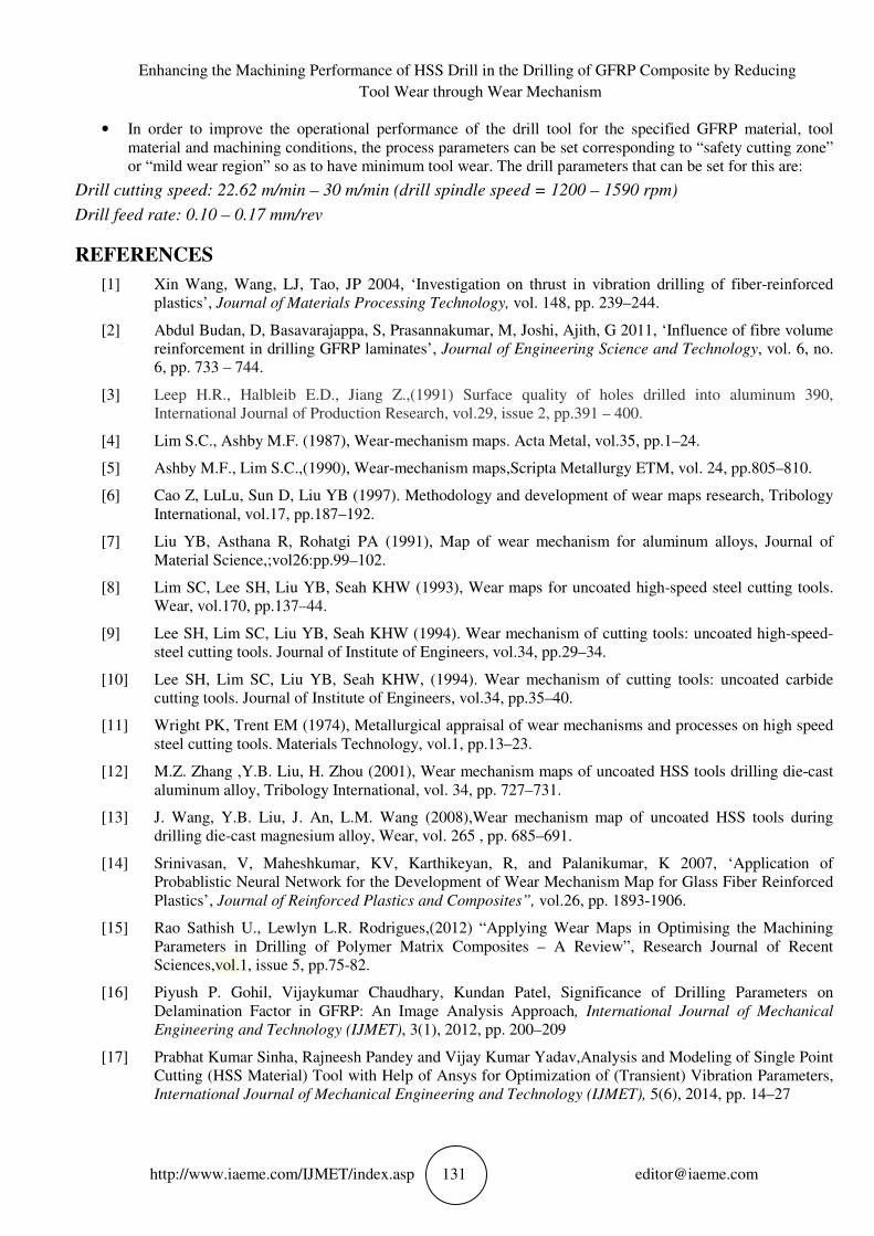
Figure 13 Wear mechanism/transition map of 6mm HSS twist drill machining GFRP composites
Another important feature of the wear rate map was the presence of a “Safety region” or “Low-wear
region” where the tool wear rate was observed to be the lowest. This indirectly informed that the wear rate
of HSS drill during machining could be minimized by maintaining the levels of the process parameters
within the safety zone boundary of the map, which might improve the tool performance and cutting tool
life. In Figure 7, Region A had the lowest wear rate ranging from −4.4 and below, which could be named
as “Safety zone”, for 6mm HSS drill machining GFRP composites. It was inferred that the life of the drill
could be enhanced if the drilling parameters were made to operate within the range, of the “Safety zone”
(Zhang, 2001, Wang, 2008). Thus, from Figure 13, for 6mm HSS drill, the process parameters
corresponding to the “Safety zone / Low wear zone” were found to be:
Drill cutting speed: 22.62 m/min – 30 m/min (drill spindle speed = 1200 – 1590 rpm)
Drill feed rate: 0.10 – 0.17 mm/rev
These machining factors could enhance the drill life for specified work material, tool material and
machining combinations.
4. CONCLUSION
• The wear rate maps were clearly delineated into Low wear region, Mild wear region, Moderate wear region,
Marginal wear region and Significant wear region. The regions in the diagram are delineated where similar
wear-rates were obtained and the boundaries are plotted according to the observed change in the wear rate.
• Micrograph observations showed adhesive pits, voids, adhesion of polyester matrix, minor cracks, deep
parallel ridges and plowing marks on the land / flank surface of the HSS drill.
• Five types of wear mechanisms were identified in the present work based on the micrograph observations of
the worn surfaces of uncoated HSS tools, during the drilling of GFRP composites.
• The main wear mechanisms in the map include built up edge, adhesive wear, adhesive and abrasive wear,
abrasive wear, plastic flow and fatigue/thermal wear.
Enhancing the Machining Performance of HSS Drill in the Drilling of GFRP Composite by Reducing
Tool Wear through Wear Mechanism
http://www.iaeme.com/IJMET/index.asp 131 [email protected]
• In order to improve the operational performance of the drill tool for the specified GFRP material, tool
material and machining conditions, the process parameters can be set corresponding to “safety cutting zone”
or “mild wear region” so as to have minimum tool wear. The drill parameters that can be set for this are:
Drill cutting speed: 22.62 m/min – 30 m/min (drill spindle speed = 1200 – 1590 rpm)
Drill feed rate: 0.10 – 0.17 mm/rev
REFERENCES
[1] Xin Wang, Wang, LJ, Tao, JP 2004, ‘Investigation on thrust in vibration drilling of fiber-reinforced
plastics’, Journal of Materials Processing Technology, vol. 148, pp. 239–244.
[2] Abdul Budan, D, Basavarajappa, S, Prasannakumar, M, Joshi, Ajith, G 2011, ‘Influence of fibre volume
reinforcement in drilling GFRP laminates’, Journal of Engineering Science and Technology, vol. 6, no.
6, pp. 733 – 744.
[3] Leep H.R., Halbleib E.D., Jiang Z.,(1991) Surface quality of holes drilled into aluminum 390,
International Journal of Production Research, vol.29, issue 2, pp.391 – 400.
[4] Lim S.C., Ashby M.F. (1987), Wear-mechanism maps. Acta Metal, vol.35, pp.1–24.
[5] Ashby M.F., Lim S.C.,(1990), Wear-mechanism maps,Scripta Metallurgy ETM, vol. 24, pp.805–810.
[6] Cao Z, LuLu, Sun D, Liu YB (1997). Methodology and development of wear maps research, Tribology
International, vol.17, pp.187–192.
[7] Liu YB, Asthana R, Rohatgi PA (1991), Map of wear mechanism for aluminum alloys, Journal of
Material Science,;vol26:pp.99–102.
[8] Lim SC, Lee SH, Liu YB, Seah KHW (1993), Wear maps for uncoated high-speed steel cutting tools.
Wear, vol.170, pp.137–44.
[9] Lee SH, Lim SC, Liu YB, Seah KHW (1994). Wear mechanism of cutting tools: uncoated high-speed-
steel cutting tools. Journal of Institute of Engineers, vol.34, pp.29–34.
[10] Lee SH, Lim SC, Liu YB, Seah KHW, (1994). Wear mechanism of cutting tools: uncoated carbide
cutting tools. Journal of Institute of Engineers, vol.34, pp.35–40.
[11] Wright PK, Trent EM (1974), Metallurgical appraisal of wear mechanisms and processes on high speed
steel cutting tools. Materials Technology, vol.1, pp.13–23.
[12] M.Z. Zhang ,Y.B. Liu, H. Zhou (2001), Wear mechanism maps of uncoated HSS tools drilling die-cast
aluminum alloy, Tribology International, vol. 34, pp. 727–731.
[13] J. Wang, Y.B. Liu, J. An, L.M. Wang (2008),Wear mechanism map of uncoated HSS tools during
drilling die-cast magnesium alloy, Wear, vol. 265 , pp. 685–691.
[14] Srinivasan, V, Maheshkumar, KV, Karthikeyan, R, and Palanikumar, K 2007, ‘Application of
Probablistic Neural Network for the Development of Wear Mechanism Map for Glass Fiber Reinforced
Plastics’, Journal of Reinforced Plastics and Composites”, vol.26, pp. 1893-1906.
[15] Rao Sathish U., Lewlyn L.R. Rodrigues,(2012) “Applying Wear Maps in Optimising the Machining
Parameters in Drilling of Polymer Matrix Composites – A Review”, Research Journal of Recent
Sciences,vol.1, issue 5, pp.75-82.
[16] Piyush P. Gohil, Vijaykumar Chaudhary, Kundan Patel, Significance of Drilling Parameters on
Delamination Factor in GFRP: An Image Analysis Approach, International Journal of Mechanical
Engineering and Technology (IJMET), 3(1), 2012, pp. 200–209
[17] Prabhat Kumar Sinha, Rajneesh Pandey and Vijay Kumar Yadav,Analysis and Modeling of Single Point
Cutting (HSS Material) Tool with Help of Ansys for Optimization of (Transient) Vibration Parameters,
International Journal of Mechanical Engineering and Technology (IJMET), 5(6), 2014, pp. 14–27


![Effect of Coolant Temperature on Machining Characteristics ... · machining. Machining with coolant will help to reduce wear, corrosion and creep of the materials [28-30]. Although,](https://img.dokumen.tips/doc/110x75/5e94a747103e90191c2608ba/effect-of-coolant-temperature-on-machining-characteristics-machining-machining.jpg)