Embed Size (px)
Citation preview
HSE-AL-FW2
SPECIFICATION FOR FULLY-WRAPPED
CARBON COMPOSITE CONTAINERS. Issue 5 January 2002
2
HSE-AL-FW2-ISSUE 5 January 2002
TABLE OF CONTENTS 1. SCOPE 4 2. SYMBOLS AND DEFINITIONS 4 2.1 Symbols 4 2.2 Definitions 5 3. DESIGN 6 3.1 Design Criteria 6 3.2 Design Verification 7 3.3 Liner Materials 7 Table I. Approved Aluminium Alloys 7 3.4 Overwrap Materials 8 3.5 Cylinder Classification 8 Table II Qualification Testing Requirements 10 3.6 Design Submission. 11 4 .QUALIFICATION TESTS 12 4.1 Prototype. 12 4.2 Liner Burst Test 13 4.3 Cylinder Burst Test 13 4.4 Ambient Cycle Test 14 4.5.Environmental Cycle Test 15 4.6 Flaw Test 15 4.7 Impact Test 16 4.8 High Velocity Impact (Gunfire) Test 17 4.9 Bonfire Test 17 4.10 Saltwater Immersion Test 18 4.11 Failure of Qualification Tests. 19 5 . MANUFACTURE, HEAT-TREATMENT AND MATERIALS TESTS 20 5.1 Liner 20 5.2 Materials Tests on the Liner 21 5.3 Composite 23 5.4 Material Tests on the Composite 23 6. INSPECTION REQUIREMENTS 23 6.1 Liner 23 6.2 Composite Cylinder 24 6.3 Autofrettage. 24
3
HSE-AL-FW2-ISSUE 5 January 2002
7. PRODUCTION TESTS 25 7.1 Hydrostatic Test. 25 7.2 Ambient Pressure Cycle and Burst Test 25 7.3 Burst Test 26 7.4 Failure of Tests 7.2 and 7.3 26 8. MARKINGS 27 8.1 Label. 27 9. IN-SERVICE PERFORMANCE MONITORING. 28 APPENDIX 1 - PERIODIC EXAMINATION AND TESTING 29 APPENDIX II - SPECIMEN REPORT 31 APPENDIX III - SPECIMEN TEST CERTIFICATES 34

4
HSE-AL-FW2-ISSUE 5 January 2002
SPECIFICATION FOR FULLY-WRAPPED CARBON/GLASS
FIBRE COMPOSITE ALUMINIUM ALLOY GAS CYLINDERS
HSE-AL-FW2
1. SCOPE This specification applies to composite gas cylinders in the range 0.5 to 100 litres
water capacity for the storage and conveyance of compressed or liquifiable gases under pressure, constructed in the form of a seamless aluminium alloy liner over-wrapped with carbon fibre and glass filament reinforced plastic to provide longitudinal and circumferential reinforcement and the composite cylinder pre-stressed by autofrettage to achieve a required level of stress distribution.
The gases that may be conveyed in these composite gas cylinders are those that are compatible with the aluminium alloy liner. The composite cylinder shall be certified by an Inspection Body approved by the Health and Safety Executive. The Inspection Body shall certify that the design, manufacture, inspection and testing were carried out in accordance with this specification. A suitable form of certificate is shown in Appendices II and III.
2. SYMBOLS AND DEFINITIONS
2.1 Symbols The following symbols are used in this specification and are defined as follows: D : Nominal outside diameter of cylinder in mm L : Nominal length of cylinder in mm p : Internal pressure in bar. po : Charging or filling pressure at 15oC in bar.
pmax : Service pressure at maximum operating or reference temperature in bar. ph : Design Test pressure in bar. pbl : Burst pressure of liner in bar. pb : Burst pressure of finished cylinder in bar. di : Internal liner diameter in mm.

5
HSE-AL-FW2-ISSUE 5 January 2002
Sc c : Circumferential carbon fibre stress in N/mm2 Scg : Circumferential glass fibre stress in N/mm2 Slc : Longitudinal carbon fibre stress in N/mm2 Slg : Longitudinal glass fibre stress in N/mm2 Scm : Circumferential stress in the liner in N/mm2 Slm : Longitudinal stress in liner in N/mm2 tcc : Thickness of circumferential carbon composite material in mm. tcg : Thickness of circumferential glass composite material in mm. tlc : Thickness of longitudinal carbon composite material in mm. tlg : Thickness of longitudinal glass composite material in mm. tm : Thickness of metal liner in mm. f : Fibre volume fraction in composite material �� : Helical or polar wrap angle Tp : Reference temperature 0 C A : Test piece sectional area in mm2
2.2 Definitions The following definitions are used in this specification as follows: 2.2.1 autofrettage: Pressure application procedure which strains the aluminium liner
past its yield point sufficient to cause permanent plastic deformation, and results in the liner having compressive stresses and the fibres having tensile stresses when at zero internal gauge pressure.
2.2.2 batch: Collective term for a set of homogeneous items or material. The number of items in a batch may vary according to the context in which the term is used, e.g. A batch of resin normally has a quantity of approximately 20 tonnes which is the quantity produced in one reactor at one time.
2.2.3 burst pressure: Pressure at which a cylinder or liner fails by rupture, when subjected to a steadily rising pressure. 2.2.4 carbon fibre: Continuous filaments of carbon laid up in tow form, used for
reinforcement. 2.2.5 composite overwrap: The combination of fibres and matrix. 2.2.6 fully wrapped cylinder: Cylinder reinforced with carbon and glass fibres in an
epoxy resin matrix to take both circumferential and longitudinal stress. 2.2.7 glass fibre: Continuous filaments of glass laid up in strand form, used for
reinforcement. 2.2.8 liner: Inner portion of the composite cylinder, comprising of an aluminium
vessel, whose purpose is both to contain the gas and transmit the gas pressure to the fibres.
2.2.9 matrix: Material which is used to bind and hold the fibres in place.

6
HSE-AL-FW2-ISSUE 5 January 2002
3. DESIGN
3.1 Design Criteria 3.1.1 After autofrettage, the maximum compressive stress state in the liner side wall
at atmospheric pressure shall not exceed 95% of the specified minimum yield stress of the aluminium alloy.
3.1.2 After autofrettage, the maximum tensile stress state in the liner side wall at 2/3
test pressure shall not exceed 60% of the specified minimum yield stress. 3.1.3 The end designs shall incorporate added materials to assure the stresses in these
areas are less than the stresses found in the cylindrical portion. 3.1.4 The design test pressure of the composite cylinder, ph, shall not be less than the
greater of:- (a) 1.5 times the specified filling pressure po, or (b) 1.18 times the intended maximum service pressure, pmax. 3.1.5 The maximum service pressure, pmax., is the pressure developed by the contents
of a container at the reference temperature, Tp. For design purposes the reference temperature for UK use shall be: for permanent gases 60oC for high pressure liquifiable gases 52.5oC for carbon-dioxide in containers fitted with safety devices 50oC 3.1.6 The filling pressure Po for permanent gases and filling ratios for liquifiable
gases at the reference filling temperature of 15oC resulting in a maximum service pressure as specified above, shall be obtained by reference to British Standard BS 5355.
3.1.7 Only parallel threads shall be used to accommodate valve fittings in accordance
with national and international standards.
7
HSE-AL-FW2-ISSUE 5 January 2002
3.2 Design Verification Netting analysis shall be used to establish the accuracy of the stress analysis
used in the design of the composite cylinder. The maximum stresses predicted by the stress analysis shall be inserted into the netting equation and compared to the applied pressure load.
3.2.1 Circumferential Stresses Equation pdi/20 = [Slc.tlc. + Slg .tlg.] .f.sin2
� + [Scm.tm.] + [Scc.tcc. + Scg.tcg ] .f
3.2.3 The stress analysis results are satisfactory if the stresses predicted by the stress
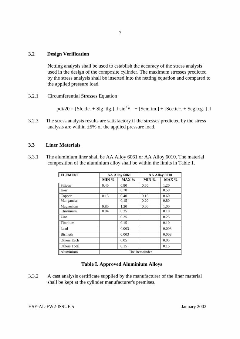
analysis are within ±5% of the applied pressure load. 3.3 Liner Materials 3.3.1 The aluminium liner shall be AA Alloy 6061 or AA Alloy 6010. The material
composition of the aluminium alloy shall be within the limits in Table 1.
ELEMENT AA Alloy 6061 AA Alloy 6010 MIN % MAX % MIN % MAX % Silicon 0.40 0.80 0.80 1.20 Iron 0.70 0.50 Copper 0.15 0.40 0.15 0.60 Manganese 0.15 0.20 0.80 Magnesium 0.80 1.20 0.60 1.00 Chromium 0.04 0.35 0.10 Zinc 0.25 0.25 Titanium 0.15 0.10 Lead 0.003 0.003 Bismuth 0.003 0.003 Others Each 0.05 0.05 Others Total 0.15 0.15 Aluminium The Remainder
Table I. Approved Aluminium Alloys
3.3.2 A cast analysis certificate supplied by the manufacturer of the liner material
shall be kept at the cylinder manufacturer's premises.

8
HSE-AL-FW2-ISSUE 5 January 2002
3.3.3 The cast shall be identified to the satisfaction of the approved Inspection Body. 3.3.4 The mechanical properties shall be specified by the manufacturer in 3.6.2.
3.4 Overwrap Materials 3.4.1 The filament materials shall be carbon fibre with an outer layer of glass fibre. 3.4.2 The resin system shall be epoxy or modified epoxy with amine or anhydride
curing agent. 3.4.3 The supplier of the filament material and of the resin system component
material shall provide sufficient documentation for the composite cylinder manufacturer to be able to identify fully the batch of materials used in the manufacture of each cylinder.
3.4.4 The materials used shall be of uniform and consistent quality. The composite
cylinder manufacturer shall verify that each new batch of materials has the correct properties and is of satisfactory quality, and maintain records from which the batch of materials used for the manufacture of each cylinder can be identified. A Certificate of Compliance from the material manufacturer is considered acceptable for the purposes of verification.
3.4.5 Batches of materials shall be identified and documented to the satisfaction of the
approved Inspection Body. 3.4.6 The manufacturer shall ensure there is no adverse reaction between the
aluminium liner and the carbon fibre by the application of a suitable protective coating to the liner prior to the wrapping process.
3.5 Cylinder Classification No alteration shall be made to the design or the method of manufacture after
approval unless such alteration has received prior agreement of the approved Inspection Body.
3.5.1 A cylinder shall be considered to be of a new design, if: a) It is manufactured in a different factory, using different equipment.(see note 1.)

9
HSE-AL-FW2-ISSUE 5 January 2002
b) It is manufactured by a significantly different process. A significant change is regarded as a change that would have a measurable change in the performance of the finished cylinder. The Approved Inspection Body shall determine when a change in process or design or manufacture is significantly different from the original qualified design.
c) The liner design has changed: i) It is manufactured in a different factory, using different
equipment.(see note 1.) ii) It is manufactured from a different alloy. d) It is manufactured using
different fibre materials. A fibre shall be considered a new fibre when any of the following conditions apply :
1. The fibre is of a different classification, e.g. Glass, aramid, carbon etc. 2. The fibre is produced from a different precursor e.g. PAN 3. The nominal fibre modulus is more than � 5% of that defined in the approved design. 4. The nominal fibre strength is more than � 5% of that defined in the approved design e) It is manufactured using different matrix materials i.e.. resin, curing agent or
accelerator.(see note 2.) f) The nominal outside diameter has changed by more than 50%. g) The design test pressure has increased by more than 60%. (see note 3.) Note 1. Where a factory moves to a different location with the same equipment, a reduced testing programme may be agreed with the Approved Inspection Body. Note 2. Where a new matrix material has been approved for an existing design, then all the manufacturers existing approved designs are approved with the new matrix system without the need for any additional qualification tests. Note 3. A cylinder may be used and marked for a lower test pressure than stated in the original type approval without additional testing. 3.5.2 For cylinders similar to an approved design, a reduced qualification testing
programme may only be necessary, see table II. A cylinder shall be considered to be a design variant compared with a previously prototype tested cylinder when any of the following conditions apply:
a) The nominal outside diameter has changed by more than 2% but less than or equal to 50%. See Note 1 b) The nominal length of the container has changed to below 2 x diameter or has increased by more than 50% of the prototype tested design length.

10
HSE-AL-FW2-ISSUE 5 January 2002
c) The base profile and/or the base thickness of the liner has changed relative to the cylinder diameter and minimum wall thickness.
d) The wall thickness of the liner has changed. e) The thickness of the fibres or the wrap pattern have changed. f) The autofrettage pressure has changed by less than 10 bar. g) There is an increase in the design test pressure of less than 10 bar, that can
be accommodated by an existing approved design. See note 2. h) There has been changes to the liner material properties outside of the
prototype tested design limits. Note 1. Where a change in diameter is between 2% and 20% a different testing
programme is applicable when compared to a diameter change of �� 20% but �50%, see table II.
Note 2. Where a cylinder is to be used for a lower pressure than that for which
design approval has been given, it shall not be deemed to be of a new design. The different testing requirements are prescribed in Table II. The approved Inspection Body will determine the level of reduced inspection required if not defined in Table II.

TEST NO
TEST NEW DESIGN
DESIGN CHANGES
DESIGN TEST PRESSURE
DIMENSIONAL CHANGES MINOR CHANGES
Changed by less than 60%
NOMINAL LENGTH
L
NOMINAL OUTSIDE
DIAMETER D
DESIGN TEST PRESSURE
BASE PROFILE OR THICKNESS
LINER WALL THICKNESS
FIBRE THICKNESS OR WRAP PATTERN CHANGE
AUTO FRETTAGE PRESSURE
2 x D >1.5L <20% >20% <50%
7.1 Hydro Test X X X X X X X X X X X 4.2 Liner
Burst Test X X X X X X X X
4.3 Burst Test X X X X X X X X X X 4.4 Ambient
Cycle Test
X X X X X X X X X X X
4.5 Environ- mental Cycle
X X
4.6 Flaw Test X X X 4.7 Impact
Test X X X X X X
4.8 Gunfire Test
X
4.9 Bonfire Test
X X
4.10. Saltwater Immers- ion Test1
X
Table II - Similar Design Qualification Testing Requirements 1 Cylinders for underwater applications only.
1
HSE-AL-FW2- Issue 5 January 2002
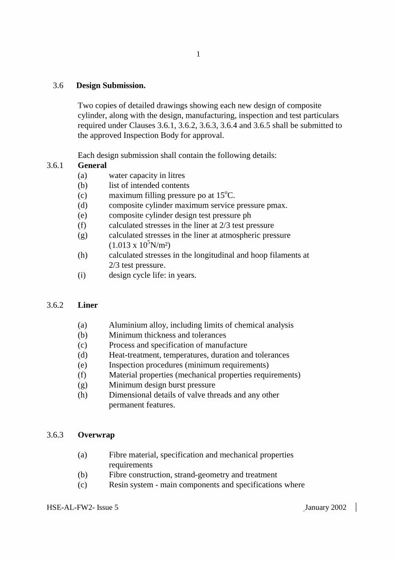
3.6 Design Submission. Two copies of detailed drawings showing each new design of composite cylinder, along with the design, manufacturing, inspection and test particulars required under Clauses 3.6.1, 3.6.2, 3.6.3, 3.6.4 and 3.6.5 shall be submitted to the approved Inspection Body for approval. Each design submission shall contain the following details: 3.6.1 General (a) water capacity in litres (b) list of intended contents (c) maximum filling pressure po at 15oC. (d) composite cylinder maximum service pressure pmax. (e) composite cylinder design test pressure ph (f) calculated stresses in the liner at 2/3 test pressure (g) calculated stresses in the liner at atmospheric pressure (1.013 x 10⁵N/m²) (h) calculated stresses in the longitudinal and hoop filaments at 2/3 test pressure. (i) design cycle life: in years. 3.6.2 Liner (a) Aluminium alloy, including limits of chemical analysis (b) Minimum thickness and tolerances (c) Process and specification of manufacture (d) Heat-treatment, temperatures, duration and tolerances (e) Inspection procedures (minimum requirements) (f) Material properties (mechanical properties requirements) (g) Minimum design burst pressure (h) Dimensional details of valve threads and any other permanent features. 3.6.3 Overwrap (a) Fibre material, specification and mechanical properties requirements (b) Fibre construction, strand-geometry and treatment (c) Resin system - main components and specifications where

2
HSE-AL-FW2.ISSUE 5 January 2002
applicable (d) Resin system - curing agent, materials and specifications where applicable (e) Resin system - accelerator, materials and specifications where applicable (f) Overwrap construction (g) Curing process, temperatures, duration and tolerances 3.6.4 Composite Cylinder (a) Autofrettage pressure and approximate duration (where applicable) (b) Identity and mark of the approved Inspection Body 3.6.5 Qualification Test Particulars The results of the design qualification tests, 4.0, demonstrating that the cylinder
design performs satisfactorily.
4 QUALIFICATION TESTS
4.1 Prototype. 4.1.1 For each prototype cylinder a prototype production batch of 30 cylinders shall
be produced, from which cylinders will be chosen at random by the Inspection Body for qualification testing.
4.1.2 Prior to the cylinders being wrapped, one liner shall be selected and subjected to
a burst test in accordance with 4.2. 4.1.3 Each completed cylinder shall be subjected to a volumetric expansion test. The permanent volumetric expansion shown by the test expressed as a
proportion of the total expansion under the test pressure shall not exceed 5% at the design test pressure specified in 3.6.1.
If the test is made by the ‘non jacket method’ the container shall be examined
for signs of leakage when subjected to the test pressure.

3
HSE-AL-FW2.ISSUE 5 January 2002
If the permanent volumetric expansion exceeds 5% of the total expansion under
the test pressure, the container shall be deemed not to comply with this specification.
The test pressure applied to the cylinder shall not exceed the design test
pressure, ph, by more than 3% or 10 bar, whichever is the lower. 4.1.4 On completion, prototype cylinders shall be selected by the Approved Inspection
Body and subjected to the following tests: (a) Burst test in accordance with 4.3. (b) Ambient temperature cycling test, in accordance with 4.4. (c) Environmental cycling test, in accordance with 4.5. (d) Flaw Test, in accordance with 4.6. (e) Impact Test, in accordance with 4.7. (f) High Velocity Impact (Gunfire) Test, in accordance with 4.8. (g) Bonfire test, in accordance with 4.9. (h) Saltwater immersion test in accordance with 4.10, where cylinders are to be used for underwater applications 4.1.5 For variation in design from the prototype cylinder it is only necessary to carry
out the tests as prescribed in Design Changes in Table II. 4.2 Liner Burst Test One cylinder liner shall be tested hydrostatically to destruction by pressurising at
a uniform rate to failure. The test shall be carried out under ambient conditions. 4.2.1 Criteria (a) The burst pressure pbl shall be not less than the minimum burst pressure,
specified in the design submission 3.6.2. (b) Failure shall initiate in the liner side wall and the liner shall remain in one
piece.
4.3 Cylinder Burst Test

4
HSE-AL-FW2.ISSUE 5 January 2002
Three cylinders shall be tested hydrostatically to destruction by pressurising at a uniform rate to failure. The test shall be carried out under ambient conditions.
4.3.1 Criteria (a) The burst pressure, pb, shall be not less than 2.0 times the test pressure, ph,
of the composite cylinder design. (b) The cylinder shall not fragment into small pieces. Failure shall initiate in the
cylinder side wall and the cylinder liner shall not fail into more than 3 major pieces. The bulk of the cylinder liner shall be considered as one piece. Any fragments contained within the body of the cylinder after the test are not to be considered.
4.4 Ambient Cycle Test Five cylinders shall be subjected to a hydrostatic pressure cycle test to test
pressure, Ph. The test shall be performed under ambient conditions. Where a cylinder is similar to an approved design, see 3.5.2, it is only necessary to test 2 cylinders. Pressure cycling tests shall be carried out using a non-corrosive fluid. The fluid
shall also be selected to ensure that it functions at the temperatures specified in the various cycle tests.
The minimum (lower cyclic) pressure shall not be more than 10% of the
maximum (upper cyclic) pressure and the frequency of reversals shall not exceed 15 cycles per minute.
Prior to the commencement of the test, it must be ensured that no air is trapped
within the system. 4.4.1 Criteria The cylinders shall withstand "N" pressurisation cycles to test pressure, Ph
without failure, where:- N = y x (250 cycles per year of design life) y = the design life in years

5
HSE-AL-FW2.ISSUE 5 January 2002
where y is a whole number and is not less than 15 years. The test shall continue until the cylinder fails or for a further N cycles,
whichever is the sooner and failure shall be by leakage.
4.5. Environmental Cycle Test One cylinder, as wrapped, shall be tested in accordance with the following sequence without deterioration, leakage or failure; (a) conditioning for 48 hours, without pressure, at not less than 60oC and 95% or greater relative humidity. (b) cycle testing to 2/3 test pressure ph for 5,000 cycles under the same conditions. (c) After the high temperature cycle sequence, the cylinder shall be stabilised at - 500C before being cycled at the lower temperature. (d) cycle testing to 2/3 test pressure for 5,000 cycles at -50oC or lower. (e) stabilisation without pressure at ambient conditions. (f) cycle testing to test pressure for 30 cycles at ambient temperature. On successful completion of these tests ; (g) the cylinder shall be hydrostatically pressurised at an uniform rate to failure. (h) the composite material shall be removed from the cylinder after the burst test and the aluminium liner shall be inspected for evidence of corrosion. 4.5.1 Criteria The burst pressure pb shall be greater than 5/3 x test pressure ph. There shall be no evidence of corrosion on the surface of the liner that is located beneath the composite material.
4.6 Flaw Test Two cylinders shall be tested in accordance with the following procedure:

6
HSE-AL-FW2.ISSUE 5 January 2002
(a) One longitudinal flaw is cut into each cylinder, in the centre of the cylindrical body of the cylinder. The flaw is made with a 1 mm thick cutter of diameter approx. 20 mm to a depth equal to at least 50% of the composite thickness and to a length between the centres of the cutter equal to five times the composite thickness. (b) One cylinders shall be tested hydrostatically to destruction by pressurising at a uniform rate to failure. The test shall be carried out under ambient conditions. (c) The other cylinder is subjected to the pressure cycling test in 4.4, but the upper cyclic pressure shall be charging pressure, po; the cylinder shall be cycled up to least 5,000 cycles without failure before the test can be stopped. This cylinder may also be used for the burst test. 4.6.1 Criteria First cylinder: Burst pressure shall be not less than 5/3 x test pressure ph. Second cylinder: Withstands at least 1000 pressure cycles to charging pressure
po, without failure by leakage. If the cylinder withstands 5,000 cycles without failure, the test may be suspended.
4.7 Impact Test One cylinder shall be tested in accordance with the following procedure: (a) The cylinder shall be dropped on the cylindrical length from a height of
4 m on to a piece of angle iron, heel uppermost, the heel edge having a radius of 1 to 2 mm. The cylinder shall land at right angles to and on the heel edge of the angle iron, impacting approximately in the centre of the side wall section.
(b) The cylinder shall be subjected to 1,000 pressure cycles from zero to
charging pressure po under ambient conditions and in accordance with 4.4.
(c) The cylinder is subjected to the burst test in 4.3.

7
HSE-AL-FW2.ISSUE 5 January 2002
4.7.1 Criteria. The cylinder shall show no evidence of leakage or damage growth during or after the pressure cycle test. Burst pressure shall be at least 5/3 times test pressure ph..
4.8 High Velocity Impact (Gunfire) Test One cylinder shall be tested in accordance with the following procedure:
(a) The cylinder shall be filled to 2/3 times test pressure with air or nitrogen. (b) The cylinder is positioned in such a way that the point of impact of the projectile shall be in the cylinder side wall and at an angle of around 45° so that the bullet would also exit through the cylinder side wall. (c) The cylinder shall be impacted by a armour piercing 7.62 mm calibre (or similar) bullet with a speed of about 850 m/s. The bullet shall be fired from a distance of not more than 45 metres. (d) The cylinder shall reveal no evidence of fragmentation failure, whether or not the bullet penetrates the cylinder. (e) The dimensions of the entrance and exit openings shall be measured and recorded. (f) For smaller diameter cylinders, <120mm diameter, a 5.6mm calibre bullet or similar may be used.
4.8.1 Criteria
The cylinder shall remain in one piece. 4.9 Bonfire Test Two cylinders shall be tested in accordance with the following procedure: (a) The cylinders shall be fitted with valves fitted with pressure relief devices, set to operate at between ph and 1.15ph, and charged with either air or nitrogen to 2/3 x test pressure.

8
HSE-AL-FW2.ISSUE 5 January 2002
(b) The bonfires shall be constructed from Kerosene soaked wood (see BS EN3 1 : 1996 Test Fire for details of the construction of a fire). (c) One cylinder shall be placed in an upright position valve uppermost , with
the lowest part of the cylinder approximately 100 mm above the firewood so that it would be exposed to total fire engulfment, but in no case should the flames be allowed to impinge directly on to the relief device. For cylinders equipped with relief devices at both ends, the bottom relief device must be shielded from any flame impingement.
(d) One cylinder shall be placed in a horizontal position with the lowest part of
the cylinder approximately 100 mm from the base the fire so that it would be exposed to fire engulfment along its whole length, but in no case should the flames be allowed to impinge directly on to the relief device.
(e) The cylinders shall be exposed to the fire until they have completely vented. 4.9.1 Criteria The cylinders' contents shall only vent through the valve pressure relief device and the cylinders shall not rupture during the test. After satisfactorily passing the test the cylinders shall be hydrostatically
pressurised to failure and the burst pressure recorded. 4.10 Saltwater immersion test. This test is mandatory for all cylinder designs intended for underwater
applications. 4.10.1 Procedure
The cylinder shall be finished as for the intended application and without
external coating unless it is an integral part of the design. a) Two closed cylinders shall be immersed in an aqueous solution containing
35g of sodium chloride/litre at 20 ��50C. b) The cylinders shall be immersed for 45 days at not less than 2/3 test pressure,
ph, then

9
HSE-AL-FW2.ISSUE 5 January 2002
c) The cylinders shall be immersed for 45 days without pressure d) The following should be monitored and recorded during the test -Cylinder internal pressure -Duration of immersion -Temperature of solution at least twice per day. e) The pressure shall be recorded at least at the beginning of the test and after 45
days, prior to de-pressurisation. Following the 90 day immersion : f) One of the two cylinders shall be subjected to an ambient cycle test (see 4.4) g) The other cylinder shall be subjected to a burst test (see 4.3) After completion of this test the cylinders shall be destroyed (e.g. by bursting),
or made incapable of holding pressure, (see 5.2.12)
4.10.2 Criteria First cylinder as appropriate for the design life as defined in section 4.4.1 Second cylinder - burst pressure shall be � 2 x ph, the design test pressure.
4.11 Failure of Qualification Tests. Composite cylinders manufactured in a production run for which the design
qualification tests do not give satisfactory results shall be rendered unserviceable for holding gas under pressure, by one of the methods listed in 5.2.12.

10
HSE-AL-FW2.ISSUE 5 January 2002
5 MANUFACTURE, HEAT-TREATMENT AND MATERIALS TESTS
5.1 Liner 5.1.1 The liner shall be manufactured by: (a) cold or hot extrusion from cast or extruded billets; or (b) cold or hot extrusion followed by cold drawing from cast or extruded billets;
or (c) cupping and cold drawing sheet or plate; or (d) necking at both ends extruded or cold drawn tube. They shall be made to a procedure that has been shown to produce containers
free from cracks or other flaws that could adversely affect the safety of the containers.
Liner end contours shall be concave to pressure and formed by forging, swaging
or spinning. They shall not be welded on and metal shall not be added in the process of closing.
5.1.2 Interior folding in the liner neck area shall be prohibited. Smooth gathering of the material in the neck in which there are no sharp rooted folds shall be acceptable. 5.1.3 Wall thickness of each liner shall be greater than or equal to the minimum design thickness specified in 3.6.2. 5.1.4 The out-of-roundness of the liner, i.e. the difference between the maximum and minimum external diameters in the same cross-section, shall not exceed 2% of the mean of these diameters. 5.1.5 The straightness of the liner, i.e. the maximum deviation of the cylindrical part of the liner from a straight line shall not exceed 3 mm/metre length. 5.1.6 The eccentricity of the liner, i.e. the deviation of the minimum and maximum wall thickness on the same cross-section, shall not exceed 10% of the mean of the two thickness. However, where the mean liner wall thickness is less than 4 mm, this deviation shall be less than 0.8 mm. 5.1.7 Each liner shall be solution heat treated at a temperature within the range 515oC to 550oC followed by water quenching at or below 32oC

11
HSE-AL-FW2.ISSUE 5 January 2002
and then artificially aged (precipitation treatment) at a temperature within the range 150oC to 200oC. 5.1.8 The minimum mechanical properties required in the finished liner after heat treatment and at room temperature shall be as specified in 3.6.2.
5.2 Materials Tests on the Liner 5.2.1 After heat treatment 5% of the liners shall be checked for hardness and shall
achieve not less than 90 Brinell or equivalent. N.B. Other equivalent methods shall be approved by the approved Inspection
Body. 5.2.2 Materials tests shall be performed on specimens cut from one fully heat treated liner in every batch, or where the number in a batch exceeds 200 from one liner in every 201 or part thereof. For the purposes of testing, a batch is a group of liners of the same design, from the same material cast, heat treated to the same conditions of temperature and duration. 5.2.3 Tensile test specimens shall be made from a strip cut longitudinally from the
liner. Its form and dimensions shall be in accordance with Standard BS EN 10002/1. The gauge length shall be 5.65 A . Only the edges shall be machined, the face and the back of the test pieces shall represent the surface of the liner as manufactured.
5.2.4 The results of the tensile test shall meet the minimum design specification requirements in 3.6.2. 5.2.5 Cold bend tests shall be made on 4 strips from 2 rings cut from the same liner as that used to provide the tensile test pieces . The width of each strip
shall not be less than 25 mm. In preparing the test piece, the face and back shall not be machined, except that the edges may be rounded off. 5.2.6 Where the liner minimum design thickness is greater than 6 mm, the width of the ring shall be not less than four times the minimum mean thickness of the liner. 5.2.7 The test pieces shall remain uncracked when bent inwards round a

12
HSE-AL-FW2.ISSUE 5 January 2002
former of diameter not more than 6 times the actual thickness of the test strip until the interior edges at the ends of the strip are at a distance apart not greater than the diameter of the former. 5.2.8 A record of the tests carried out shall be kept at the premises of the cylinder manufacturer. Suitable forms of test certificate are shown in Appendix II. 5.2.9 If any of the test results are not satisfactory, and if the Inspection Body is satisfied that this was due to an error carrying out the test, a re-test may be authorised using the same liner otherwise, at the discretion of the manufacturer, either (a) the test in question shall be repeated on two specimens, one from the same liner or test ring as for the first test and another one from a liner or test ring from the same batch, and if both results are satisfactory the batch may be accepted, or (b) the batch may be re-heat treated in accordance with 5.1.7 and re-tested as specified under 5.2. and if the results are satisfactory the batch may be accepted. 5.2.10 Where solution heat treatment has been shown to be inadequate, liners may be subjected to re-solution treatment, once only, followed by artificial ageing. 5.2.11 Where heat treatment furnace records show artificial ageing has been inadequate, additional time at the ageing temperature shall be given. 5.2.12 If the test results, having allowed for re-testing or re-heat treatment, are not satisfactory, liners in the batch shall be rendered unserviceable by one of the following methods: (a) crushing by mechanical means (b) producing an irregular hole in the top dome equivalent at least to 10% of the area of the top dome, or in the case of a thin walled liner piercing it in at least three places. (c) cutting up. Drilling a hole is not considered to be satisfactory for this purpose.

13
HSE-AL-FW2.ISSUE 5 January 2002
5.3 Composite 5.3.1 The composite cylinder shall be fabricated from an aluminium liner fully over-
wrapped with resin impregnated continuous fibres. Winding pattern shall be "helical" and "hoop wrap" applied under controlled tension to develop the design composite thickness and as specified in 3.6.3.
Note: Liners may be stripped and re-wound provided that the overwrap has not
been cured. The liner must not be over-wrapped if it has been damaged or scored by the stripping process.
5.3.2 After winding is completed the composite shall be cured using a controlled
temperature profile as specified in 3.6.3. The maximum temperature shall be such that the mechanical properties of the liner material are not adversely affected.
5.4 Material Tests on the Composite The filament materials shall be subjected to an impregnated strand test in
accordance with American Society for Testing and Material Standard ASTM 2343 for glass and ASTM D4018-81 for carbon fibre, or identified equivalent specifications accepted by the approved Inspection Body.
The strength of acceptable fibres shall be not less than specified in 3.6.3.
6. INSPECTION REQUIREMENTS
6.1 Liner 6.1.1 Each batch of liners shall be examined and dimensionally checked to ensure compliance with the design specification. The following inspections shall be carried out in accordance with the manufacturer's Quality Assurance procedures: (a) Visual Inspection of Surface Finish (b) Dimensions - Clause 3.6.2 (c) Neck Folds - Clause 5.1.2 (d) Min Wall Thickness - Clause 5.1.3

14
HSE-AL-FW2.ISSUE 5 January 2002
(e) Out of Roundness - Clause 5.1.4 (f) Straightness - Clause 5.1.5 (g) Eccentricity - Clause 5.1.6 (h) Water Capacity - Clause 3.6.1 (i) Weight (j) Thread Specification - Clause 3.6.2
6.2 Composite Cylinder 6.2.1 Each batch of composite cylinders shall be examined and dimensionally checked
to ensure compliance with the design specification. The following inspections shall be carried out in accordance with the manufacturer's Quality Assurance procedures:
(a) Visual Inspection of Surface Finish (b) Dimensions (c) Minimum Thickness (d) Label (e) Water Capacity (f) Weight (g) Cleanliness 6.2.2 The internal cleanliness shall meet the following minimum requirements: (a) No grease; for general cleanliness the level of hydrocarbon contamination
shall be less than 500 mg/m2.
(b) For oxygen and oxidising gases the hydrocarbon contamination shall be less than 100 mg/m2.
(c) No swarf or other debris or materials inside the cylinder. (d) No matrix material e.g. resin, on the thread and sealing surfaces on the neck.
6.3 Autofrettage. If cylinders are subjected to an autofrettage operation the level of autofrettage
pressure shall be as specified in clause 3.6.4 and following parameters shall be recorded:
autofrettage pressure;

15
HSE-AL-FW2.ISSUE 5 January 2002
length of application of this pressure; maximum expansion of the cylinder. 7 PRODUCTION TESTS
7.1 Hydrostatic Test. Each completed cylinder shall be subjected to a volumetric expansion test in
4.1.3 at the design test pressure specified in 3.6.1 above.
The cylinder is acceptable if the permanent volumetric expansion expressed as a proportion of the total expansion is not more than 5%.
The test pressure applied to the cylinder shall not exceed the design test pressure, ph, by more than 3% or 10 bar, whichever is the lower.
7.2 Ambient Pressure Cycle and Burst Test One completed cylinder per batch of 202 (or less) shall be subjected to a
hydrostatic pressure cycle test to test pressure, ph followed by a burst test. Pressure cycling tests shall be carried out using a non-corrosive fluid. The minimum (lower cyclic) pressure shall not be more than 10% of the
maximum (upper cyclic) pressure and the frequency of reversals shall not exceed 15 cycles per minute.
Prior to the commencement of the test, it must be ensured that no air is trapped
within the system. The test shall be performed under ambient conditions. 7.2.1. Criteria The cylinders shall withstand "N" pressurisation cycles to test pressure ph without failure by burst or leakage, where: N = y x 250 y = the number of years of design life where y is a whole number and is not less than 15 years. N.B. In no case shall "N" be less than 3,750 cycles.

16
HSE-AL-FW2.ISSUE 5 January 2002
If there are no signs of leakage of failure, the outcome is satisfactory and the
cylinder shall be hydrostatically tested to destruction by pressurising at a uniform rate up to the failure pressure, the failure pressure shall be noted.
7.2.1.1 Burst Criteria (a) The burst pressure, pb, shall be not less than 5/3 times the test pressure, ph,
of the composite cylinder design. (b) The cylinder shall not fragment into small pieces. Failure shall initiate in the
cylinder side wall and the cylinder liner shall not fail into more than 3 major pieces. The bulk of the cylinder liner shall be considered as one piece. any fragments contained within the body of the cylinder, after the test, are not to be considered.
7.3 Burst Test 7.3.1 One completed cylinder per batch of 202 (or less) shall be tested hydrostatically
to destruction by pressurising at a uniform rate up to the failure pressure, the failure pressure shall be noted.
7.3.1.1 Criteria. a) Burst pressure pb shall be at least 2.0 times the test pressure ph (b) The cylinder shall not fragment into small pieces. Failure shall initiate in the
cylinder side wall and the cylinder liner shall not fail into more than 3 major pieces. The bulk of the cylinder liner shall be considered as one piece. any fragments contained within the body of the cylinder after the test are not to be considered.
7.3.2 The cylinder subjected to the pressure cycle test (7.2) may be used for this test. 7.4 FAILURE OF TESTS 7.2 AND 7.3 If the results of the tests are unsatisfactory a second test may be allowed if
approved Inspection Body suspects the validity of the initial test. Alternatively the cause of failure may be investigated and if this is identified the
defective cylinders in the batch shall be removed. Two cylinders shall be

17
HSE-AL-FW2.ISSUE 5 January 2002
chosen from the remaining cylinders in the batch and these shall then be subjected to the batch tests 7.2 and 7.3.
In the case of a batch failure the approved Inspection Body may require further
tests to qualify the remaining cylinders in the batch. If the batch fails the second series of tests, the batch of cylinders shall be
scrapped and rendered unserviceable for holding gas under pressure by one of the methods in 5.2.12.
8 MARKINGS 8.1 Label 8.1.1 Each finished composite cylinder which satisfies the requirement of this
specification shall be permanently and legibly marked with a label incorporated in the reinforcing wrap on the side near the outlet end of the cylinder, showing the following:
(a) the mark of this specification: HSE-AL-FW2 (b) the aluminium alloy of the liner e.g. AA 6061 (c) filling pressure in bar units at 15oC (permanent gases) or (d) maximum charge weight in kg units and tare weight of cylinder in kg,
prefixed with "TARE" (liquefiable gases) (e) design test pressure in bar units, prefixed with "PH". (f) manufacturer's mark. (g) mark of the approved Inspection Body. (h) date (month and year) of the first hydrostatic pressure test. (i) minimum water capacity in litres, suffixed by "L" (j) the cylinder serial number. (k) design life: "N" years (l) thread identity e.g. M18 (m) Country of origin (n) nominal empty weight, suffixed by “KG” (o) special provisions e.g. underwater. 8.1.2 Additional markings (e.g. re-test dates, customer names etc) may be contained
on the main label or applied as a secondary label securely affixed to the cylinder side wall and over-coated with epoxy resin.
8.1.3 The marking shall not be less than 3 mm in height.

18
HSE-AL-FW2.ISSUE 5 January 2002
8.1.4 The layout of the label and marking shall be part of the registered design. (NOTE - Appendices I, II and III do not form part of the mandatory
requirements of the specification and are recommendations only). 9 IN-SERVICE PERFORMANCE MONITORING
The principal aim of the in-service performance monitoring is to be satisfied that the long term behaviour of a new composite cylinder design does not deteriorate faster than the original performance tests would predict and also that the cylinders are not unnecessarily scrapped where a satisfactory level of performance has been proven and future integrity can be assured.
9.1 Fifteen years from the date of the first hydrostatic pressure test all composite
cylinders shall be returned to the manufacturer or competent organisation authorised to test composite cylinders on behalf of the manufacturer, for reassessment. The manufacturer, in conjunction with the competent organisation where appropriate, and the approved Inspection Body shall establish suitability for further service. The Health and Safety Executive shall be advised.
9.2 The cylinders may continue in service to the end of their design lifetime or for a
further period of up to 15 years, whichever is the shorter, only with the written consent of the manufacturer and the approved Inspection Body.
9.3 Thirty years from the date of the first hydrostatic pressure test any composite
cylinders still in service shall be returned to the manufacturer or competent organisation) authorised to test composite cylinders on behalf of the manufacturer, for reassessment. Thereafter they may continue in service to the end of their design life only with the written consent of the manufacturer and the approved Inspection Body.
9.4 At the end of the cylinders' designated design life, they shall be withdrawn from
service and shall be rendered unserviceable by a method listed in 5.2.12.

19
HSE-AL-FW2.ISSUE 5 January 2002
APPENDIX 1 - PERIODIC EXAMINATION AND TESTING 1. Composite cylinders to this specification shall be examined for defects
externally by visual inspection at each cylinder fill, by a person having appropriate training, experience and facilities.
2. Within the period of 3 years* from the date of the last hydraulic pressure test
every composite cylinder to this specification shall be examined for defects externally and internally, and before continuing in service, subjected to a hydrostatic pressure test in accordance with the British Standard BS 5430 Part 3 1990. Clause 4.7.3. and the manufacturer's recommended procedure, by the manufacturer or a station authorised to test composite cylinders on behalf of the manufacturer.
3. The procedure for external and internal inspection shall be specified by the
manufacturer, including the appropriate damage identification criteria for the acceptance or rejection of cylinders for further service. This procedure may refer to relevant guidance published by the Compressed Gas Association in the USA (CGA Pamphlet C-6.2 1988) and the relevant sections of BS 5430: Part 3 1990 in respect of non-wrapped and internal surfaces, excluding any method of cleaning or surface preparation that might damage the composite.
4. A cylinder with superficial damage only that has no adverse effect on its safety
and integrity, may continue in service. 5. Cylinders with minor damage below the rejection level in accordance with the
criteria specified under paragraph 3 of this Appendix including minor flaws in the reinforcement that may be repaired, shall be returned to the manufacturer or his authorised tester/repairer for examination or repair and subject to hydrostatic pressure test in accordance with the manufacturer's recommended procedure.
6. Cylinders shall be rejected if they do not meet the volumetric expansion criteria
or if any flaw has grown following repair and testing. 7. Rejected cylinders shall be rendered unserviceable from holding gas under
pressure by one of the methods listed in 5.2.12 of this specification. 8. In the event of doubt or dispute in connection with paragraphs 4 to 7 of this
Appendix, the manufacturer and, if necessary, the approved Inspection Body shall be consulted.

20
HSE-AL-FW2.ISSUE 5 January 2002
9. Records of all periodic examinations and testing shall be held by the
manufacturer together with materials and test certificates and inspection reports relating to the manufacture of the cylinder, for the lifetime of the cylinder.
*NB After the first re-test, the re-test performance data will be reviewed by the manufacturer, or the competent organisation, or the approved Inspection Body where appropriate. Satisfactory performance will result in the extension of the re-test period from 3 to 5 years. The Health and Safety Executive will need to be notified of the change.

21
HSE-AL-FW2.ISSUE 5 January 2002
APPENDIX II - SPECIMEN REPORT APPROVED INSPECTION BODY'S REPORT ON: THE MANUFACTURE OF FULL WRAPPED COMPOSITE ALUMINIUM ALLOY GAS CYLINDERS TO SPECIFICATION HSE-AL-FW2 ___________________________________________________________________ Approved Inspection Body ___________________________________________ Approved Inspection Body's Mark Certificate No. _______________________________ Place ________________________ Date _______ Cylinders Manufactured by _____________________________ Manufacturer's Mark Manufactured for Consigned to _________________________________________ Quantity _______ Overall size ________ Outside Diameter by ______ long Serial Numbers to inclusive Specification HSE-AL-FW2 Drawing No ________ Date of Hydrostatic Pressure Test _______________ Test Pressure _______________________________ Water Capacity _________________________ Gas ___________ Filling Pressure (Permanent)_____________

22
HSE-AL-FW2.ISSUE 5 January 2002
Filling Ratio (Liquifiable) ______________ Mass of Container (in kg) Minimum _____ Maximum ______ Without valve Minimum ______ Maximum ______ With valve
(Note: Items in brackets below refer to the Clauses of specification HSE-AL-FW2) Each cylinder was made by over-wrapping a seamless aluminium alloy liner with resin impregnated filament reinforcement. Liner material designated as was supplied by and the cast analysis was within the required limits (3.3.1 Table I). Each liner was produced by an approved process in accordance with (§5.1) heat treated by solution treatment followed by water quenching with artificial ageing (§5.1.7) and checked for hardness (5.2.1). The results of the tensile test and bend tests have been found satisfactory (5.2.4, 5.2.7). Overwrap was applied by winding under controlled tension filament. Glass Carbon designated _____________ _________________ supplied by _____________ __________________ Impregnated with resin designated _______________________________________ manufactured by Identified by package number and cured after wrapping to the manufacturer's specification. Filaments strand strength (3.2.7) and reinforcement shear strength (3.2.8) was verified and found satisfactory. Calculated stress levels on the aluminium liner and the reinforcement filaments satisfy design requirements (3.1.1 and 3.1.2). Each cylinder was subjected to an autofrettage pressure of ___________ for approximately ____________ Each cylinder was subjected to a hydrostatic pressure test (7.1) at the test pressure stated above and volumetric expansion was found to be satisfactory. The results of the batch pressure cycle and burst tests (7.2,7.3) were satisfactory.

23
HSE-AL-FW2.ISSUE 5 January 2002
Each cylinder has been marked as required by the Specification (8). WE HEREBY CERTIFY that each of the above cylinders meet in full the requirements of the Specification. For and on behalf of the manufacturer ..............................................................................
For and on behalf of the Approved Inspection Body ........................................................
24
HSE-AL-FW2.ISSUE 5 January 2002
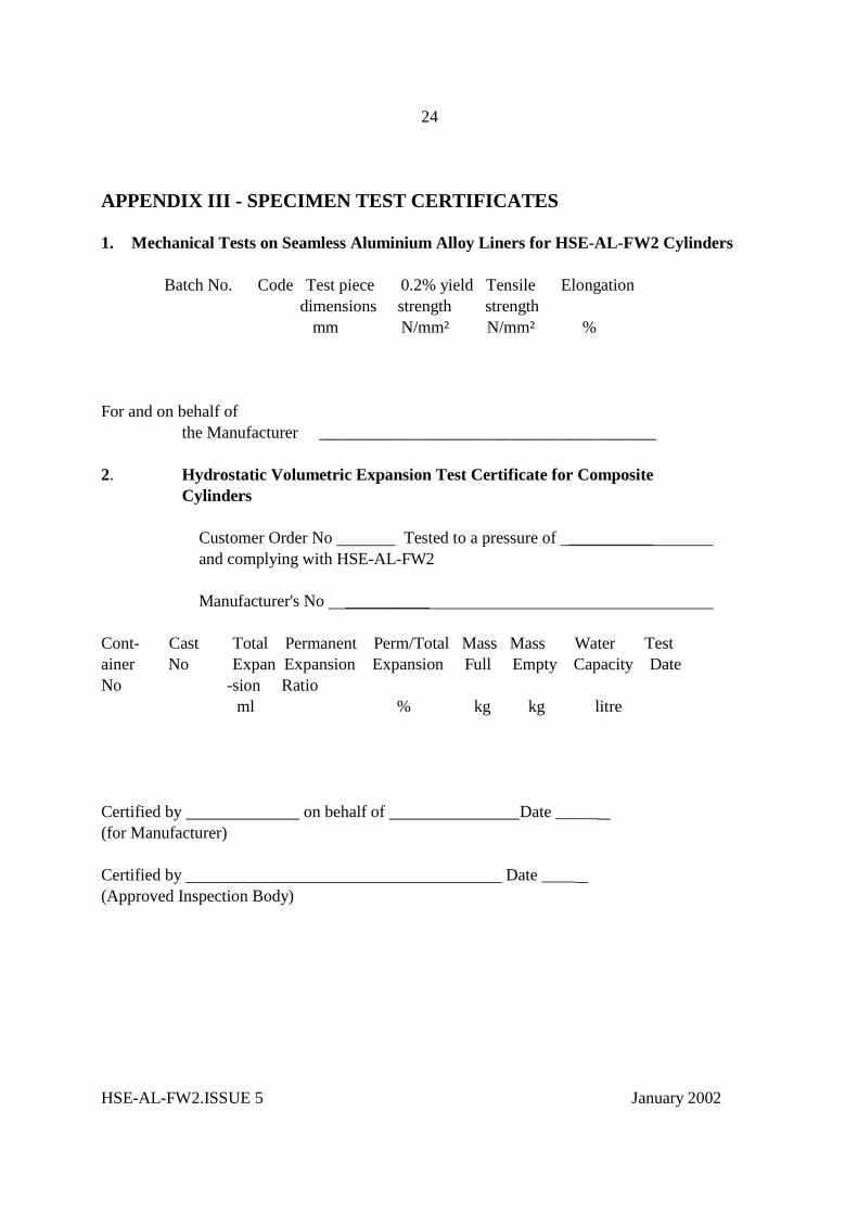
APPENDIX III - SPECIMEN TEST CERTIFICATES 1. Mechanical Tests on Seamless Aluminium Alloy Liners for HSE-AL-FW2 Cylinders Batch No. Code Test piece 0.2% yield Tensile Elongation dimensions strength strength mm N/mm² N/mm² % For and on behalf of the Manufacturer ________________________________________ 2. Hydrostatic Volumetric Expansion Test Certificate for Composite Cylinders
Customer Order No Tested to a pressure of __________ and complying with HSE-AL-FW2 Manufacturer's No __________ Cont- Cast Total Permanent Perm/Total Mass Mass Water Test ainer No Expan Expansion Expansion Full Empty Capacity Date No -sion Ratio ml % kg kg litre Certified by on behalf of Date _____ (for Manufacturer) Certified by Date ____ (Approved Inspection Body)