Embed Size (px)
Citation preview
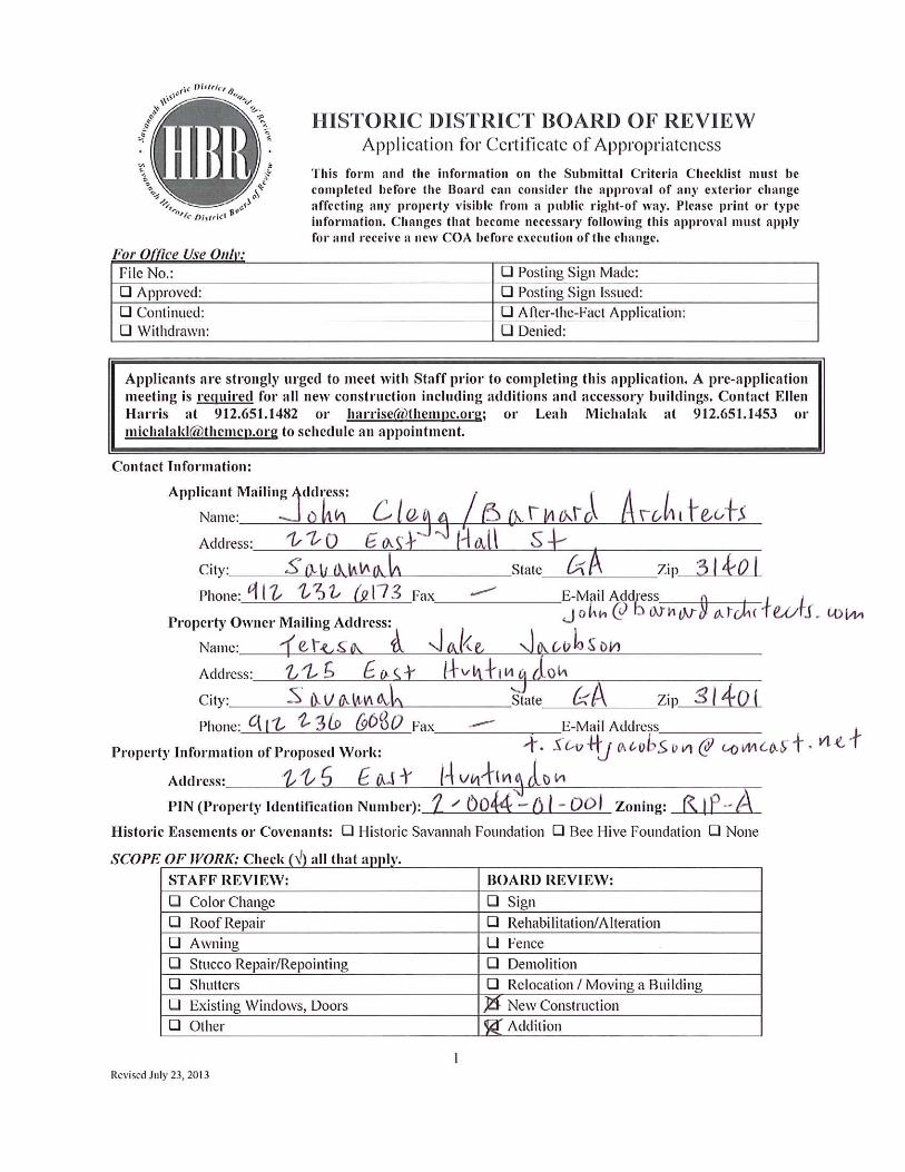
Barnard Architects Updated 9.17.2013 Printed 9.17.2013
Scope of Work for New Carriage House and Rear Porch 225 East Huntingdon
Page 1
Scope of Work for
New Carriage House & New Rear Porch 225 East Huntingdon Street
General
1. This project was presented to the SPR on August 8, 2013. The need for approval from the Zoning Board of Appeals is noted below.
2. Per 8-3025: 75% max building coverage is permitted. The new carriage house and new porch will increase the lot coverage from 42% to 52%.
New Carriage House
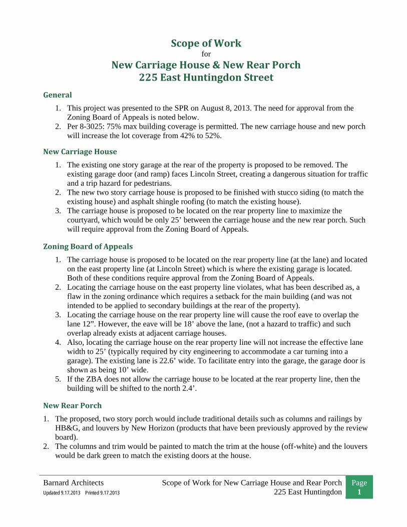
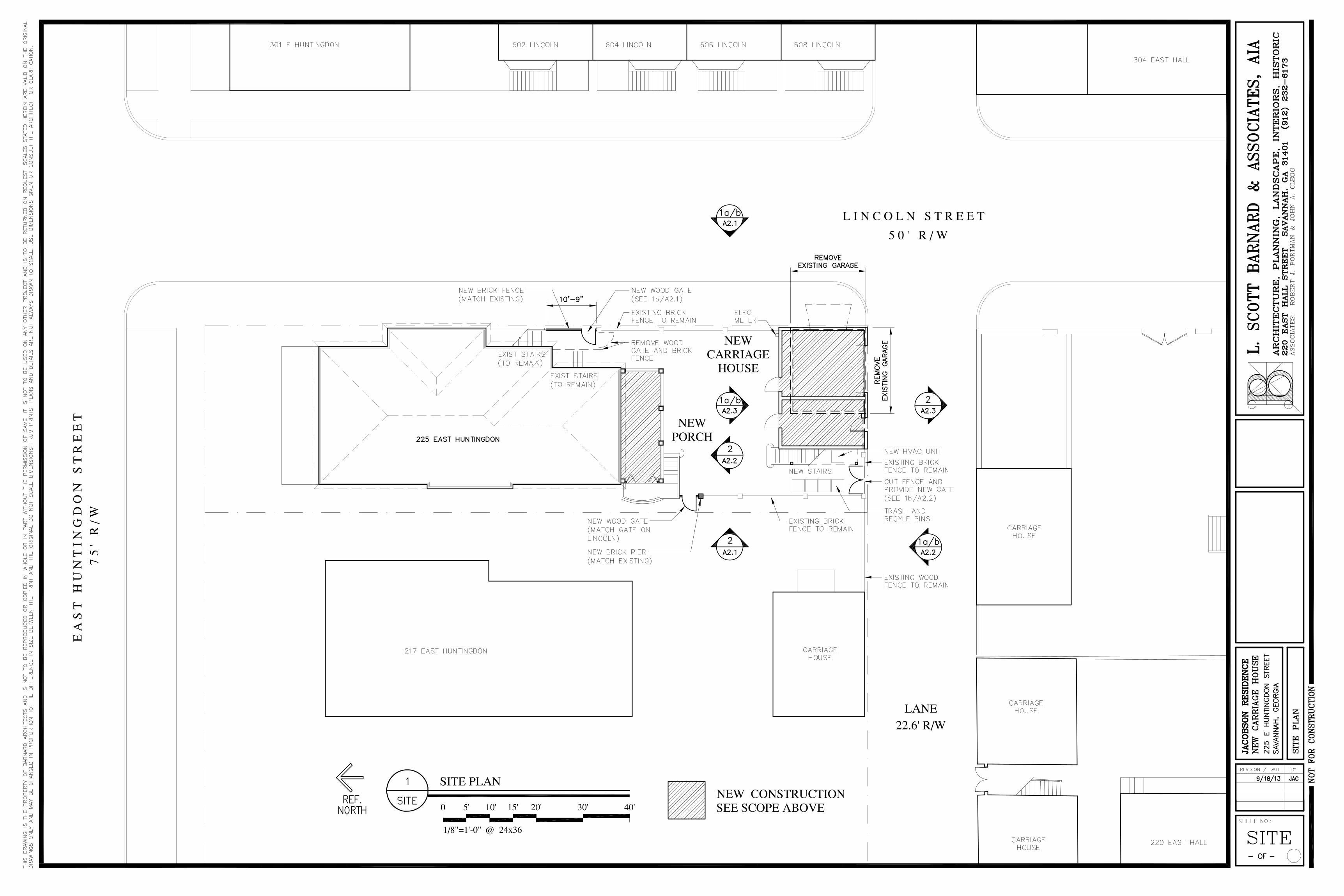
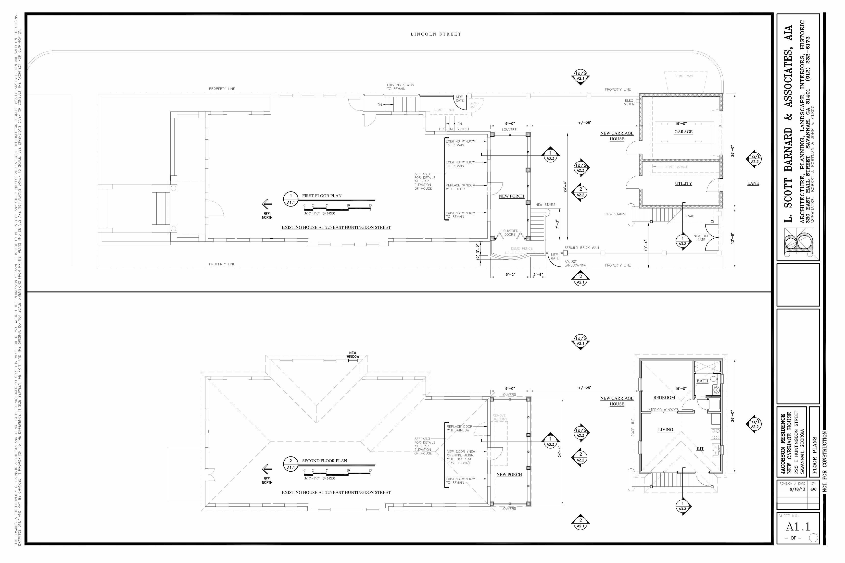
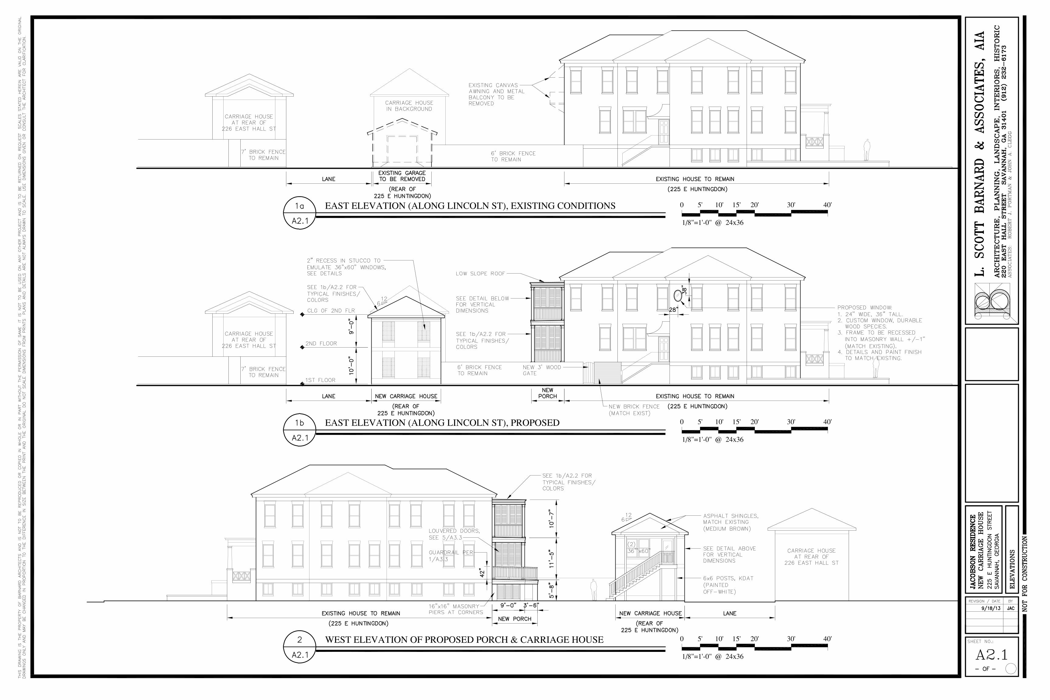
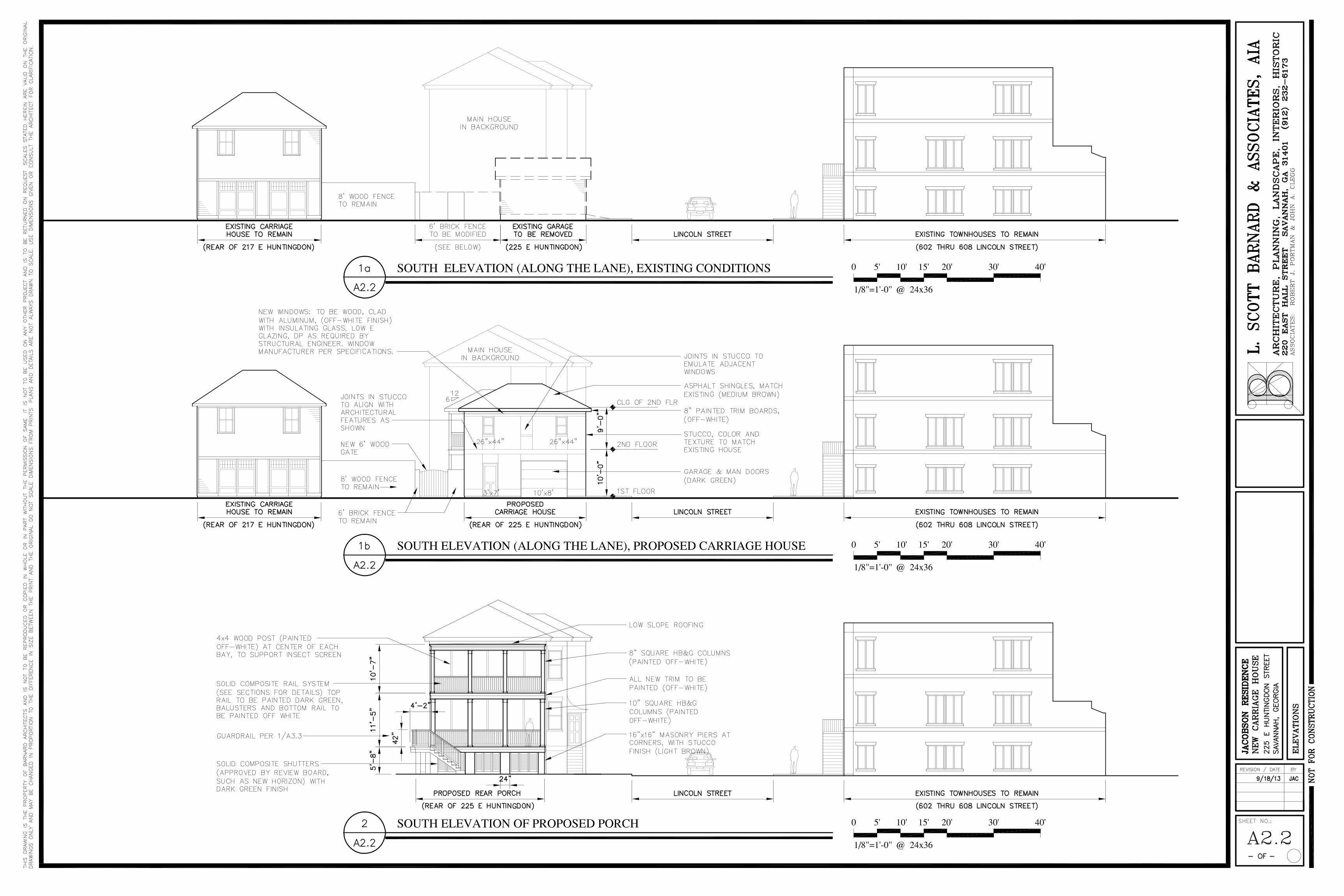
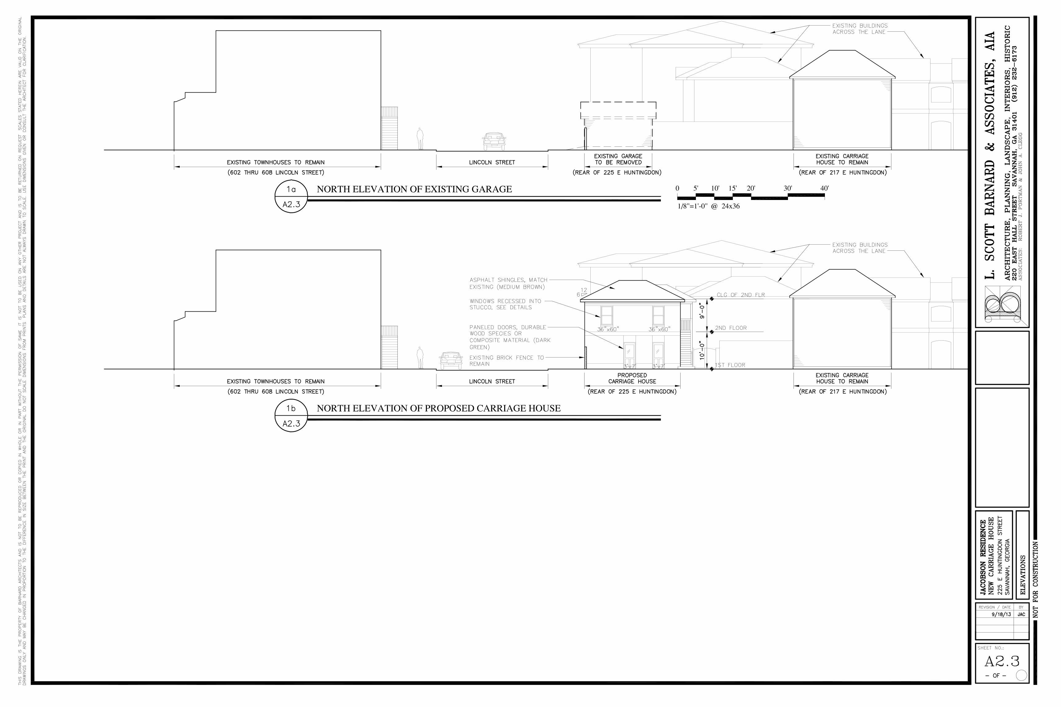
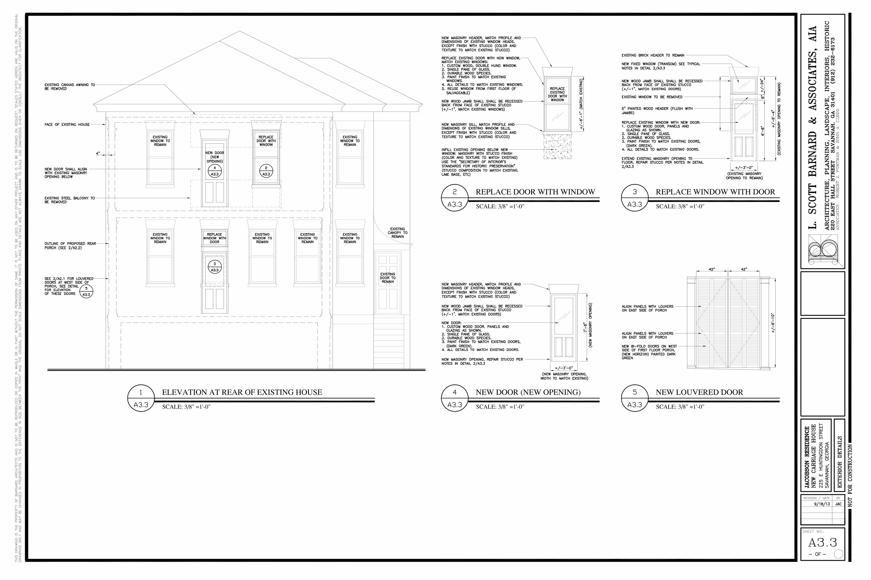
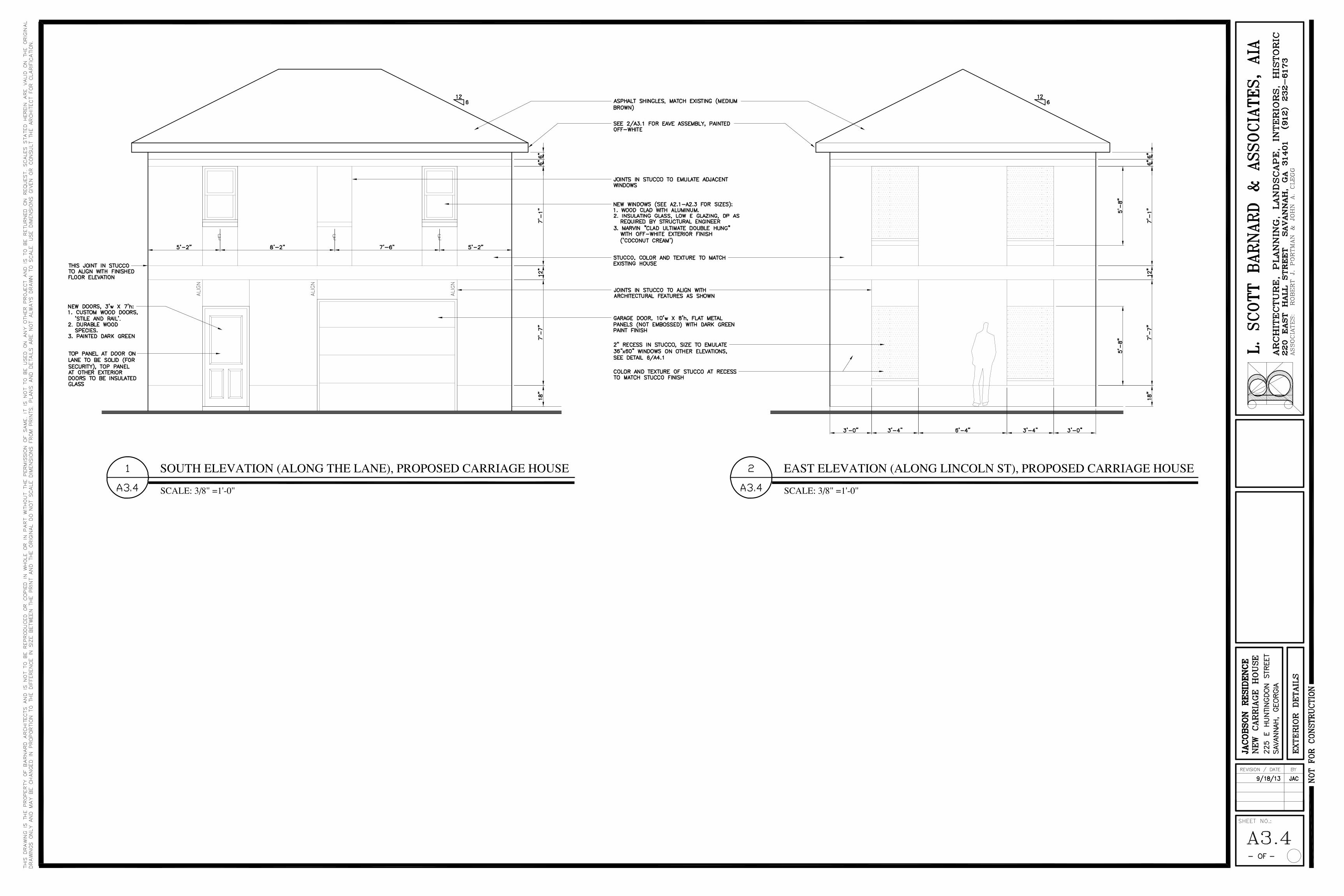
1. The existing one story garage at the rear of the property is proposed to be removed. The existing garage door (and ramp) faces Lincoln Street, creating a dangerous situation for traffic and a trip hazard for pedestrians.
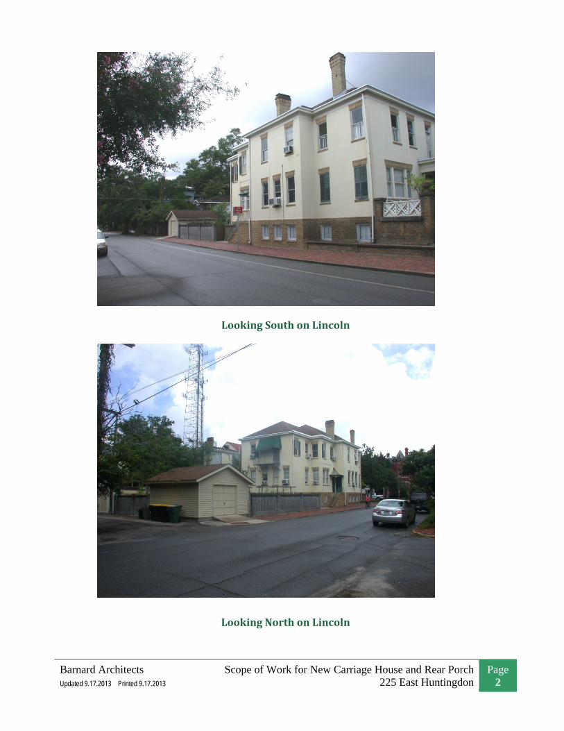
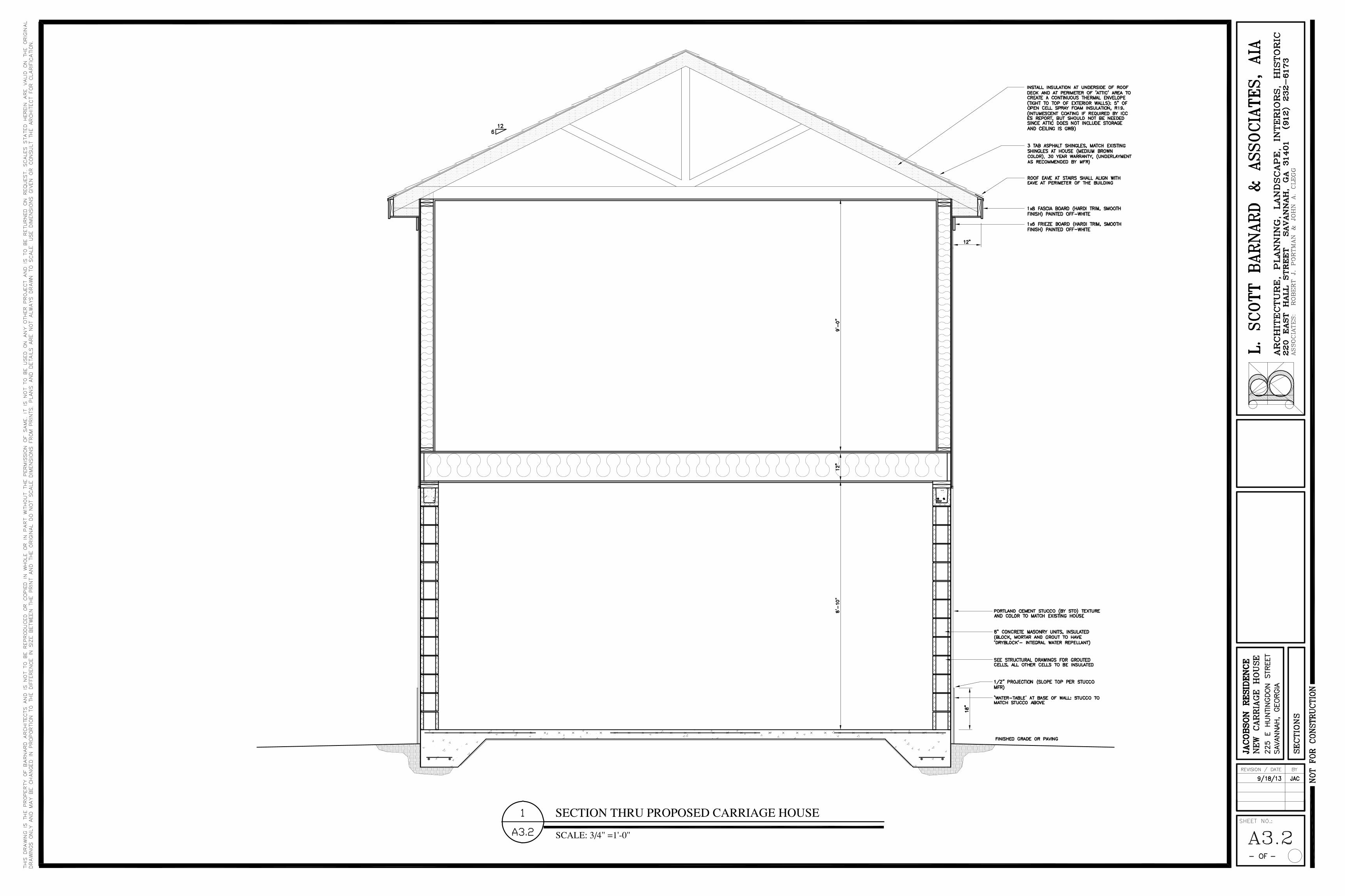
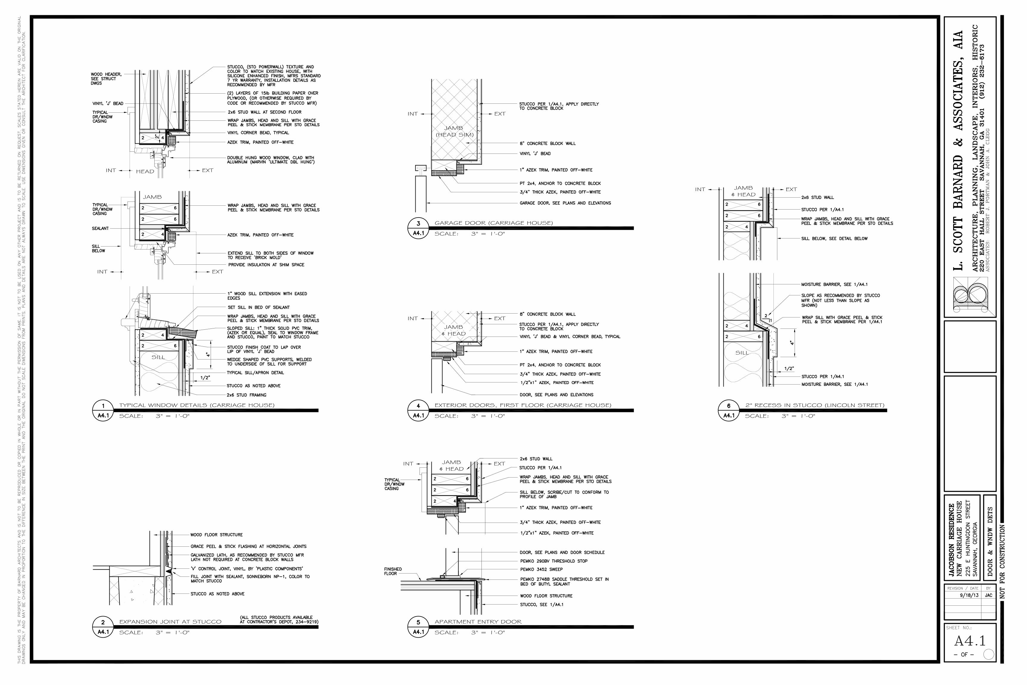
2. The new two story carriage house is proposed to be finished with stucco siding (to match the existing house) and asphalt shingle roofing (to match the existing house).
3. The carriage house is proposed to be located on the rear property line to maximize the courtyard, which would be only 25’ between the carriage house and the new rear porch. Such will require approval from the Zoning Board of Appeals.
Zoning Board of Appeals
1. The carriage house is proposed to be located on the rear property line (at the lane) and located on the east property line (at Lincoln Street) which is where the existing garage is located. Both of these conditions require approval from the Zoning Board of Appeals.
2. Locating the carriage house on the east property line violates, what has been described as, a flaw in the zoning ordinance which requires a setback for the main building (and was not intended to be applied to secondary buildings at the rear of the property).
3. Locating the carriage house on the rear property line will cause the roof eave to overlap the lane 12”. However, the eave will be 18’ above the lane, (not a hazard to traffic) and such overlap already exists at adjacent carriage houses.
4. Also, locating the carriage house on the rear property line will not increase the effective lane width to 25’ (typically required by city engineering to accommodate a car turning into a garage). The existing lane is 22.6’ wide. To facilitate entry into the garage, the garage door is shown as being 10’ wide.
5. If the ZBA does not allow the carriage house to be located at the rear property line, then the building will be shifted to the north 2.4’.
New Rear Porch
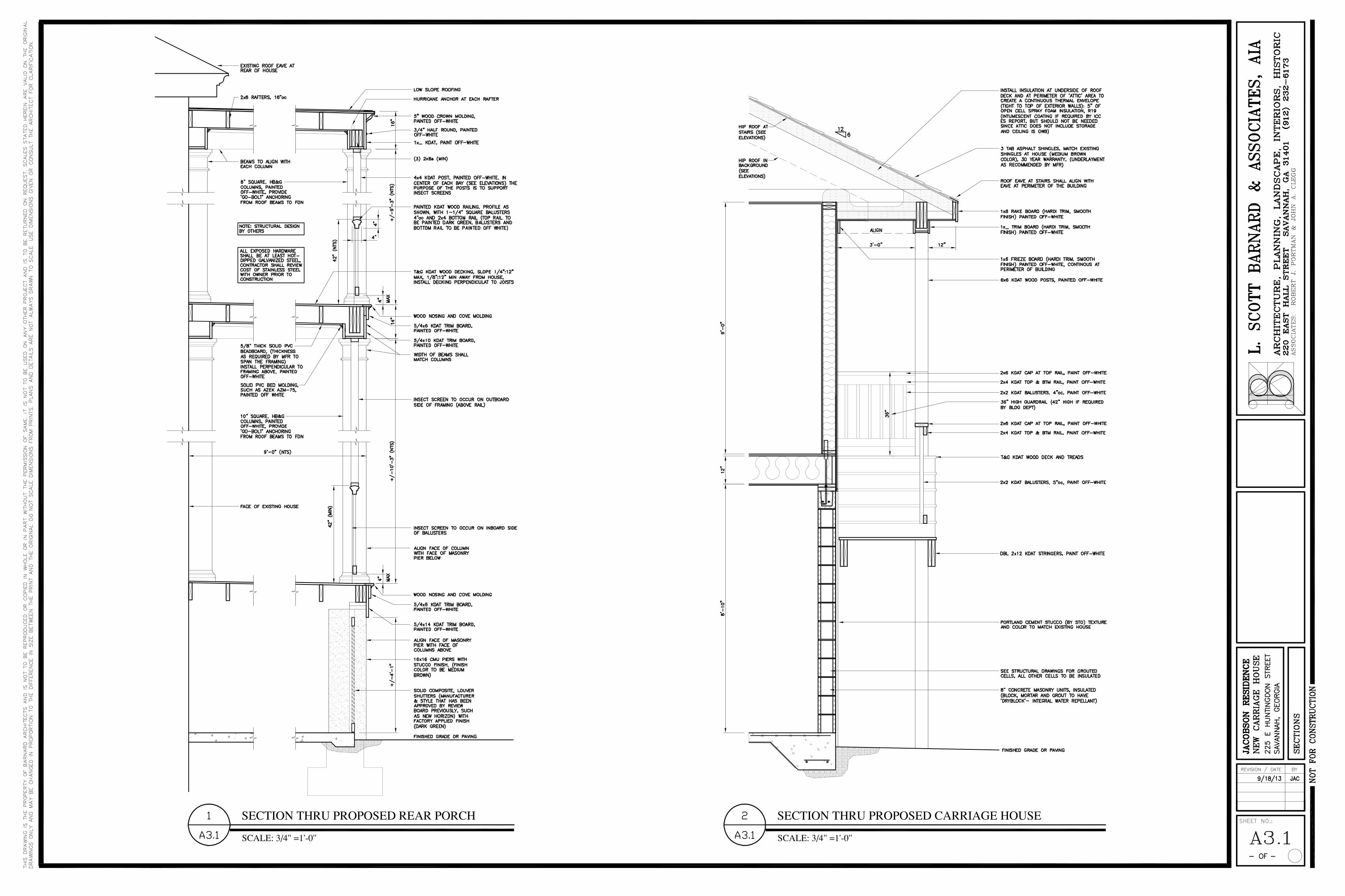
1. The proposed, two story porch would include traditional details such as columns and railings by HB&G, and louvers by New Horizon (products that have been previously approved by the review board).
2. The columns and trim would be painted to match the trim at the house (off-white) and the louvers would be dark green to match the existing doors at the house.
Barnard Architects Updated 9.17.2013 Printed 9.17.2013
Scope of Work for New Carriage House and Rear Porch 225 East Huntingdon
Page 2
Looking South on Lincoln
Looking North on Lincoln
Barnard Architects Updated 9.17.2013 Printed 9.17.2013
Scope of Work for New Carriage House and Rear Porch 225 East Huntingdon
Page 4
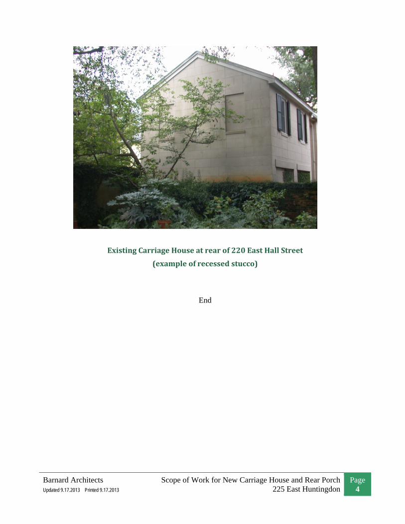
Existing Carriage House at rear of 220 East Hall Street
(example of recessed stucco)
End

c l o p a y. c o m
series
CLASSIC™ COLLECTION
Model T40L, Long Traditional Panel with Optional Brilliance® Collection Marquise Window Design
VALUE
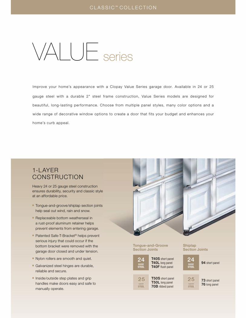
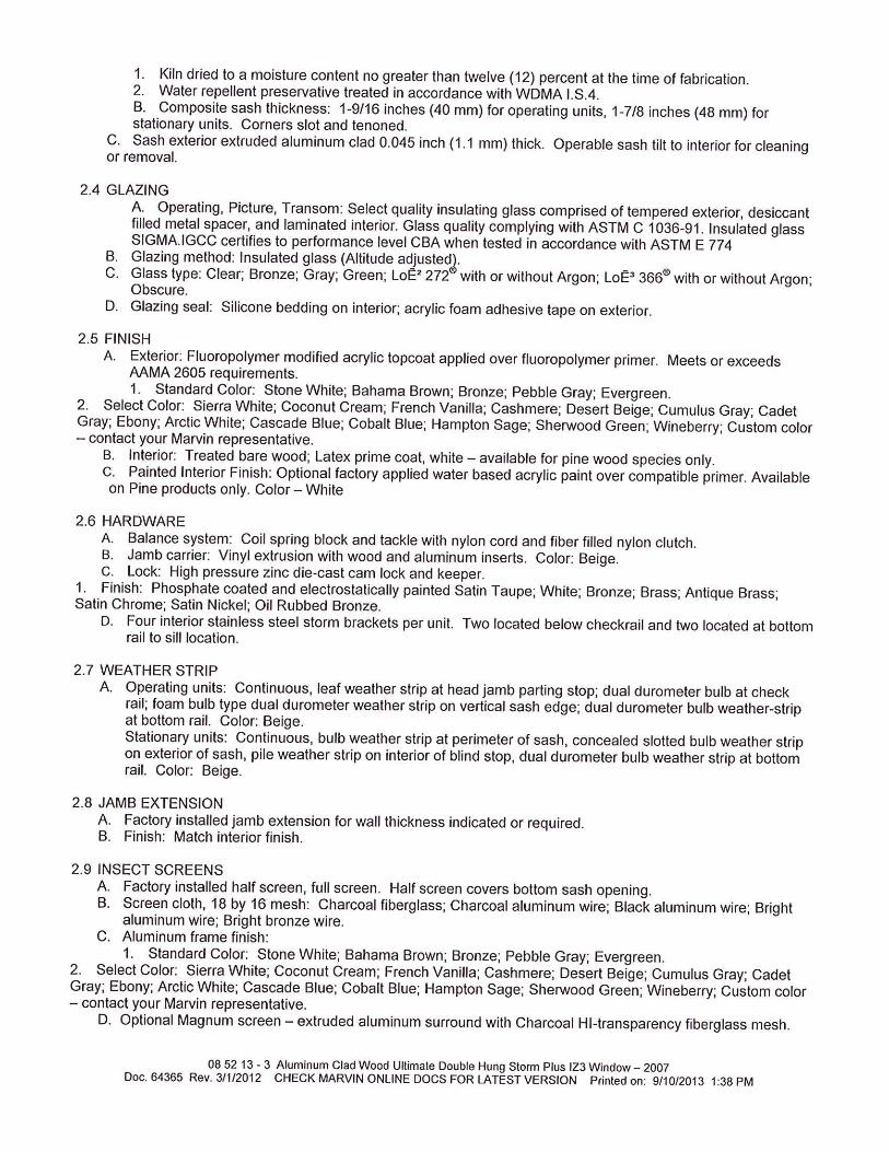
1-LAYER CONSTRUCTION Heavy 24 or 25 gauge steel construction ensures durability, security and classic style at an affordable price.
� Tongue-and-groove/shiplap section joints help seal out wind, rain and snow.
� Replaceable bottom weatherseal in a rust-proof aluminum retainer helps prevent elements from entering garage.
� Patented Safe-T-Bracket® helps prevent serious injury that could occur if the bottom bracket were removed with the garage door closed and under tension.
�� Nylon rollers are smooth and quiet.
� Galvanized steel hinges are durable, reliable and secure.
� Inside/outside step plates and grip handles make doors easy and safe to manually operate.
25GAUGESTEEL
73 short panel76 long panel
GAUGE STEEL
2494 short panel
25GAUGESTEEL
T50S short panelT50L long panel70B ribbed panel
T40S short panelT40L long panelT40F flush panel
GAUGE STEEL
24
C L A S S I C ™ C O L L E C T I O N
seriesVALUEImprove your home’s appearance with a Clopay Value Series garage door. Available in 24 or 25
gauge steel with a durable 2" steel frame construction, Value Series models are designed for
beautiful, long-lasting per formance. Choose from multiple panel styles, many color options and a
wide range of decorative window options to create a door that f its your budget and enhances your
home’s curb appeal.
Tongue-and-Groove Section Joints
Shiplap Section Joints
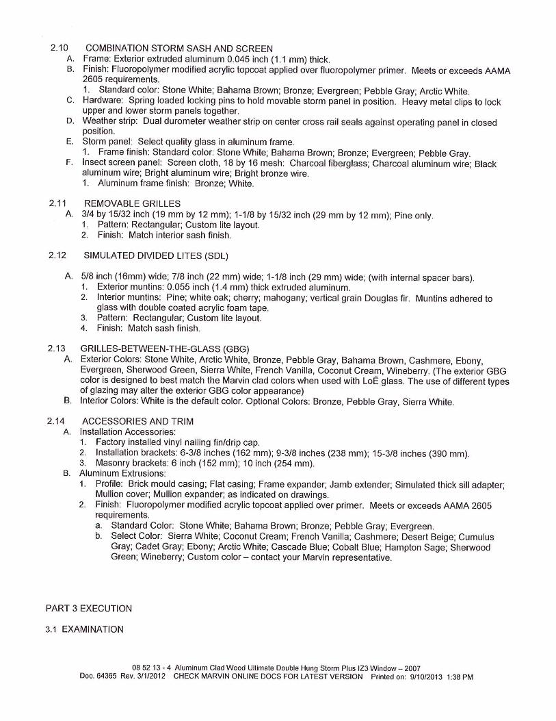
Traditional ShortComplements homes with traditional styling. Models T40S, T50S, 94 and 73.
Traditional LongIdeal for ranch style homes. Models T40L, T50L and 76.
FlushPerfect for contemporary and some transitional style homes. Model T40F.
RibbedGood option for transitional style homes or utility structures. Model 70B.
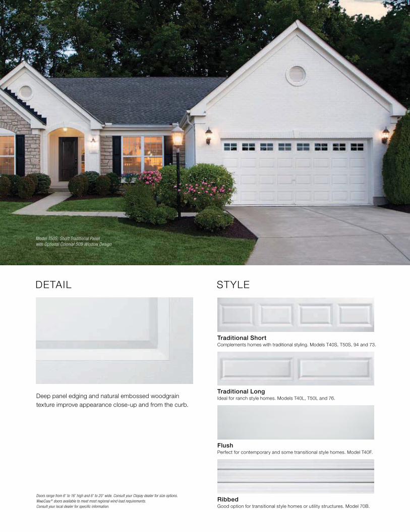
Deep panel edging and natural embossed woodgrain texture improve appearance close-up and from the curb.
Doors range from 6' to 16' high and 6' to 20' wide. Consult your Clopay dealer for size options. WINDCODE ® doors available to meet most regional wind load requirements.Consult your local dealer for specific information.
DETAIL STYLE
Model T50S, Short Traditional Panel with Optional Colonial 509 Window Design
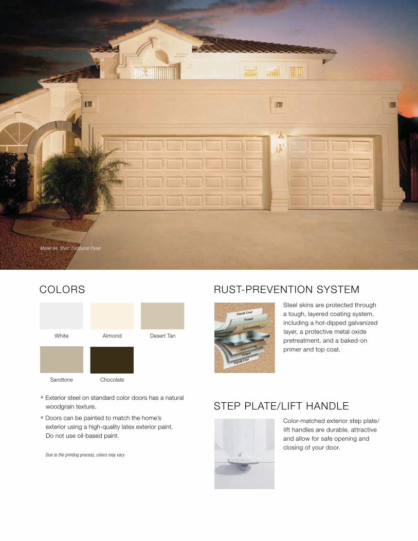
COLORS
Due to the printing process, colors may vary.
White Almond Desert Tan
ChocolateSandtone
� Exterior steel on standard color doors has a natural woodgrain texture.
� Doors can be painted to match the home’s exterior using a high-quality latex exterior paint. Do not use oil-based paint.
RUST-PREVENTION SYSTEMSteel skins are protected through a tough, layered coating system, including a hot-dipped galvanized layer, a protective metal oxide pretreatment, and a baked-on primer and top coat.
STEP PLATE/LIFT HANDLEColor-matched exterior step plate/lift handles are durable, attractive and allow for safe opening and closing of your door.
Model 94, Short Traditional Panel
A FOCUS ON
WARRANTY
L I F EL I M I T E D
PAINT SYSTEM
Models T40, 94
WARRANTY
PAINT SYSTEM
15 YRL I M I T E D
Models T50, 73, 76
WARRANTY
PAINT SYSTEM
10 YRL I M I T E D
Model 70B
WARRANTY
10 YRL I M I T E D
WINDOWS
All Models
WARRANTY
3 YRL I M I T E D
HARDWARE
All Models
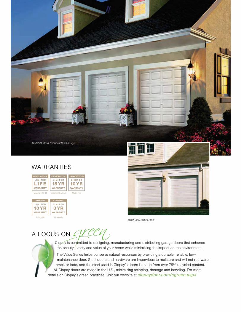
WARRANTIES
Clopay is committed to designing, manufacturing and distributing garage doors that enhance the beauty, safety and value of your home while minimizing the impact on the environment.
The Value Series helps conserve natural resources by providing a durable, reliable, low-maintenance door. Steel doors and hardware are impervious to moisture and will not rot, warp,
crack or fade, and the steel used in Clopay’s doors is made from over 75% recycled content. All Clopay doors are made in the U.S., minimizing shipping, damage and handling. For more
details on Clopay’s green practices, visit our website at clopaydoor.com/cgreen.aspx
Ct
T
cAl
details
Model 73, Short Traditional Panel Design
Model 70B, Ribbed Panel
Tool & Truck Rental Get It Installed For the Pros Gift Cards Help
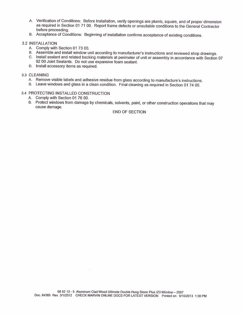
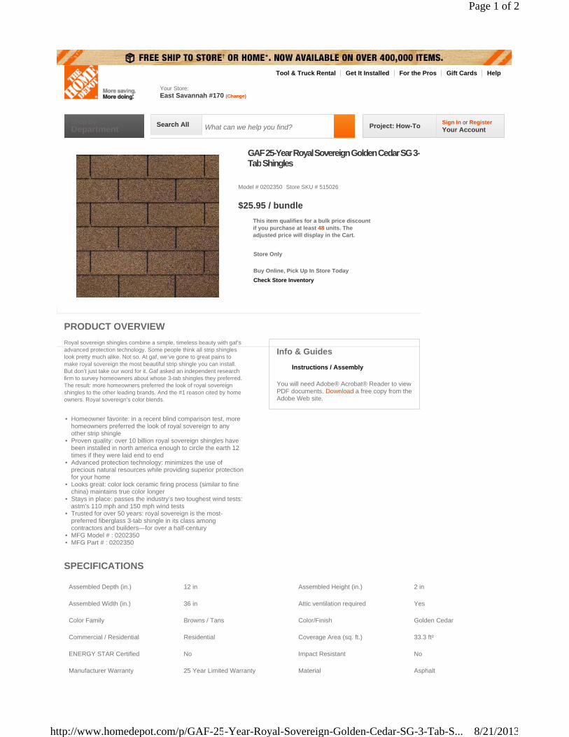
GAF 25-Year Royal Sovereign Golden Cedar SG 3-Tab Shingles
Model # 0202350 Store SKU # 515026
This item qualifies for a bulk price discountif you purchase at least 48 units. Theadjusted price will display in the Cart.
$25.95 / bundle
Check Store Inventory
Store Only
Buy Online, Pick Up In Store Today
Royal sovereign shingles combine a simple, timeless beauty with gaf’s advanced protection technology. Some people think all strip shingles look pretty much alike. Not so. At gaf, we’ve gone to great pains to make royal sovereign the most beautiful strip shingle you can install. But don’t just take our word for it. Gaf asked an independent research firm to survey homeowners about whose 3-tab shingles they preferred. The result: more homeowners preferred the look of royal sovereign shingles to the other leading brands. And the #1 reason cited by home owners. Royal sovereign’s color blends.
• Homeowner favorite: in a recent blind comparison test, more homeowners preferred the look of royal sovereign to any other strip shingle
• Proven quality: over 10 billion royal sovereign shingles have been installed in north america enough to circle the earth 12 times if they were laid end to end
• Advanced protection technology: minimizes the use of precious natural resources while providing superior protection for your home
• Looks great: color lock ceramic firing process (similar to fine china) maintains true color longer
• Stays in place: passes the industry’s two toughest wind tests: astm’s 110 mph and 150 mph wind tests
• Trusted for over 50 years: royal sovereign is the most-preferred fiberglass 3-tab shingle in its class among contractors and builders—for over a half-century
• MFG Model # : 0202350• MFG Part # : 0202350
Info & Guides
Instructions / Assembly
You will need Adobe® Acrobat® Reader to view PDF documents. Download a free copy from the Adobe Web site.
PRODUCT OVERVIEW
SPECIFICATIONS
Assembled Depth (in.) 12 in Assembled Height (in.) 2 in
Assembled Width (in.) 36 in Attic ventilation required Yes
Color Family Browns / Tans Color/Finish Golden Cedar
Commercial / Residential Residential Coverage Area (sq. ft.) 33.3 ft²
ENERGY STAR Certified No Impact Resistant No
Manufacturer Warranty 25 Year Limited Warranty Material Asphalt
East Savannah #170 (Change)
Your Store:
Shop ByDepartment Project: How-To
Sign In or RegisterYour Account
Search All What can we help you find?
Page 1 of 2
8/21/2013http://www.homedepot.com/p/GAF-25-Year-Royal-Sovereign-Golden-Cedar-SG-3-Tab-S...
Sto Guide Specification Sto Corp. is an ISO 9001:2000 Registered Company Page 1 of 17 Revised: August, 2008
Sto Corp. 3800 Camp Creek Parkway Building 1400, Suite 120 Atlanta, GA 30331 Phone: 404-346-3666 Fax: 404-346-7422 www. stocorp.com
Sto Specification S103
StoPowerwall ™ Stucco: Fiber Reinforced Portland Cement Stucco for Concrete, Masonry and Frame Construction
Section 09220 – Portland Cement Plaster/Stucco
This specification is intended for use by the design/construction professional and any user of Sto products to assist in developing project specifications and to provide guidance on the application of StoPowerwall™ Stucco to sound supporting construction. StoPowerwall Stucco consists of a portland cement plaster that serves as a base for any Sto acrylic or silicone enhanced finish. StoPowerwall Stucco functions as a decorative and protective exterior wall covering. As with any exterior wall covering the proper integration of other components of construction, in particular, the use of flashing to direct water to the exterior, is essential. Efflorescence is a normal occurrence in portland cement based products and can affect final appearance of finish products installed over stucco. Some degree of cracking is normal in portland cement stucco and should be expected. Cracking is generally not caused by a material defect in the stucco and can be minimized by following sound construction practice such as the proper installation of lath, the use of properly graded sand, the proper incorporation of stress relief joints, moist curing of the stucco after it has been applied, and proper sequencing of construction to avoid stresses on the stucco. This specification provides a guideline for the use and specification of StoPowerwall Stucco. Specific wall assemblies incorporating StoPowerwall Stucco are also listed in code compliance reports available on request from Sto Corp. or from ICC Evaluation Services, Inc. Notes in Italics, such as this one, are explanatory and intended to guide the design professional/specifier and user in the proper selection and use of materials. This specification should be modified where necessary to accommodate individual project conditions. PART 1 GENERAL 1.01 SECTION INCLUDES
A. Materials and installation of exterior stucco wall covering. 1.02 RELATED SECTIONS (add/delete, depending on specific project requirements):
A. Section 03300: Cast-In-Place concrete
B. Section 04200: Unit Masonry
C. Section 06115: Sheathing
D. Section 07190: Vapor Barriers
E. Section 07500: Membrane Roofing
F. Section 07270: Air Barriers
G. Section 07620: Sheet Metal Flashing and Trim
H. Section 07920: Sealants and Caulking
I. Section 08400: Exterior Entrance Doors
J. Section 08500: Exterior Windows
K. Section 09260: Gypsum Board Systems 1.03 REFERENCED DOCUMENTS (add/delete depending on specific project requirements)
A. ASTM Standards:
SPECIFICATION S103 -- StoPowerwall ™ Stucco: Portland Cement Stucco for Concrete, Masonry, and Frame Construction
Sto Guide Specification Sto Corp. is an ISO 9001:2000 Registered Company Page 2 of 17 Revised: August, 2008
1. A 641 Standard Specification for Zinc-Coated (Galvanized ) Carbon Steel Wire 2. A 653 Specification for Sheet Steel Zinc coated (Galvanized) by the Hot-Dip
Process, Commercial Quality 3. B 69 Specification for Roller Zinc 4. C 144 Specification for Aggregate for Masonry Mortar 5. C 578 Specification for Preformed, Cellular Polystyrene Thermal Insulation 6. C 847 Standard Specification for Metal Lath 7. C 897 Standard Specification for Aggregate for Job-Mixed Portland Cement-
Based Plasters 8. C 1032 Standard Specification for Woven Wire Plaster Base 9. C 1063 Standard Specification for Installation of Lathing and Furring for Portland
Cement Plaster 10. C 1177 Specification for Glass Mat Gypsum for Use as Sheathing 11. C 1396 Specification for Gypsum Board 12. D 226 Standard Specification for Asphalt-Saturated Organic Felt Used in Roofing
and Waterproofing 13. D 1784 Specification for Rigid Poly (Vinyl Chloride) (PVC) Compounds and
Chlorinated Poly (Vinyl Chloride) (CPVC) Compounds 14. E 84 Test Method for Surface Burning Characteristics of Building Materials 15. E 119 Method for Fire Tests of Building Construction and Materials 16. E136 Behavior of Materials in Vertical Tube Furnace at 750˚C 17. E 283 Test Method for Determining Rate of Air Leakage Through Exterior
Windows, Curtain Walls, and Doors Under Specified Pressure Differences Across the Specimen
18. E 330 Test Method for Structural Performance of Windows, Curtain Walls, and Doors by Uniform Static Air Pressure Difference
19. E 331 Test Method for Water Penetration of Exterior Windows, Skylights, Doors, and Curtain Walls by Uniform Static Air Pressure Difference
20. E 2430 Standard Specification for Expanded Polystyrene (“EPS”) Thermal Insulation Boards For Use in Exterior Insulation and Finish Systems (“EIFS”).
21. G 155 Standard Practice for Operating Light-Exposure Apparatus (Xenon-Arc Type) With and Without Water for Exposure of Nonmetallic Materials
B. APA Engineered Wood Association
1. E 30 Residential and Commercial Construction Guide
C. EIMA (EIFS Industry Members Association)
1. EIMA Guideline Specification for Expanded Polystyrene (EPS) Insulation Board
D. Gypsum Association
1. GA-253 Application of Gypsum Sheathing
E. ICBO ES (International Conference of Building Officials Evaluation Service)
1. AC 11 Acceptance Criteria for Cementitious Exterior Wall Coatings
1.04 DESIGN REQUIREMENTS
A. Structural (wind and axial loads)
1. Design for maximum allowable deflection, normal to the plane of the wall, of L/360
SPECIFICATION S103 -- StoPowerwall ™ Stucco: Portland Cement Stucco for Concrete, Masonry, and Frame Construction
Sto Guide Specification Sto Corp. is an ISO 9001:2000 Registered Company Page 3 of 17 Revised: August, 2008
2. Design for wind load in conformance with code requirements. Consult applicable code compliance report.
B. Moisture Control
1. Prevent the accumulation of water into or behind the stucco, either by condensation or
leakage into the wall construction, in the design and detailing of the wall assembly. a. Provide corrosion resistant flashing to direct water to the exterior where it is likely
to penetrate components in the wall assembly, including, above window and door heads, beneath window and door sills, at roof/wall intersections, decks, abutments of lower walls with higher walls, above projecting features, and at the base of the wall.
b. Air Leakage Prevention—prevent excess air leakage in the design and detailing of the wall assembly. Provide continuity between air barrier components in the wall assembly.
c. Vapor Diffusion and Condensation-- perform a dew point analysis of the wall assembly to determine the potential for accumulation of moisture in the wall assembly as a result of water vapor diffusion and condensation. Adjust insulation thickness and/or other wall assembly components accordingly to minimize the risk of condensation. Avoid the use of vapor retarders on the interior side of the wall in warm, humid climates.
d. On framed wall construction provide a code compliant moisture barrier over sheathing. Note: Building codes vary with respect to the type moisture barrier required and the number of layers. (see note below)
e. Protect sills of rough openings with barrier membrane. Where casing bead is used back-to-back at expansion joints, back joints with barrier membrane. Refer to Sto details.
Note: The IBC and IRC require minimum 2 layers of Grade D building paper over wood-based sheathing behind stucco. See IBC Section 2510.6 (2006 Ed.) or IRC Section R703.2 (2006 Ed.). StoGuard™ with Sto EmeraldCoat® and StoGuard™ with Sto Gold Coat® are recognized by ICC-ES as acceptable alternates to code compliant water-resistive barriers, see ICC-ES Evaluation Report ESR-1233.
C. Grade Condition
1. Do not specify the stucco for use below grade or on surfaces subject to continuous or
intermittent water immersion or hydrostatic pressure. Provide minimum 4 inch (100 mm) clearance above earth grade, minimum 2 inch (51 mm) clearance above finished grade (pavers/sidewalk). Provide increased clearance in freeze/thaw climate zones.
D. Sloped surfaces, including Foam Trim and Projecting Architectural Features attached to
stucco.
1. Avoid the use of stucco on build-outs or weather exposed sloped and horizontal surfaces (refer to 2 and 3 below).
2. Build out trim and projecting architectural features from the stucco wall surface with code compliant EPS foam. All foam trim and projecting architectural features must have a minimum 1:2 [27°] slope along their top surface. All foam horizontal reveals must have a minimum 1:2 [27°] slope along their bottom surface. Increase slope for northern climates to prevent accumulation of ice/snow and water on surface. Where trim/feature or bottom surface of reveal projects more than 2 inches (51 mm) from the face of the wall plane, protect the top surface with waterproof base coat. Avoid the use of trim and features that exceed the maximum allowable thickness of EPS permitted by code (typically 4 inches [100 mm]) unless approved by the code official. Periodic inspections and increased maintenance may be required to maintain surface

SPECIFICATION S103 -- StoPowerwall ™ Stucco: Portland Cement Stucco for Concrete, Masonry, and Frame Construction
Sto Guide Specification Sto Corp. is an ISO 9001:2000 Registered Company Page 4 of 17 Revised: August, 2008
integrity of finishes on weather exposed sloped surfaces. Limit projecting features to easily accessible areas and limit total area to facilitate maintenance and minimize maintenance burden. Refer to Sto details.
3. Do not use EPS foam on weather exposed projecting ledges, sills, or other projecting
features unless supported by framing or other structural support and protected with metal coping or flashing. Refer to Sto details.
E. Joints
1. Provide two piece expansion joints in the stucco system where building movement is anticipated: at joints in the substrate or supporting construction, where the system is to be installed over dissimilar construction or substrates, at changes in building height, at floor lines, at columns and cantilevered areas.
2. Provide one piece expansion joints every 144 ft2 (13 m2)*. Cut and wire tie lath to the expansion joint accessory so lath is discontinuous beneath the accessory. Do not exceed length to width ratio of 2-1/2:1 in expansion joint layout and do not exceed more than 18 feet (5.5 m) in any direction without an expansion joint. Where casing bead is used back-to-back as the expansion joint, back the joint with barrier membrane.
*Note: the requirement for a one piece expansion joint every 144 ft2 (13 m2) may be waived in the following cases: 1. when two-piece expansion joints exist every 144 ft2 (13 m2), and 2. on solid substrates without metal lath such as cast-in-place concrete and concrete masonry units provided joints in the supporting construction exist at appropriate intervals and they are reflected in the stucco. In such cases joint spacing in the stucco shall not exceed 250 ft2 (23 m2).
3. Provide one piece expansion joints at through wall penetrations, for example, above
and below doors or windows.
Note: the requirement for one piece expansion joints at through wall penetrations may be waived in the following case: when another type of expansion joint is provided in lieu of the one piece expansion joint, for example, back-to-back casing beads.
4. Provide minimum 3/8 inch (9 mm) wide joints where the system abuts windows, doors
and other through wall penetrations. 5. Provide appropriate accessories at stucco terminations and joints. 6. Provide appropriate sealant at stucco terminations. 7. Indicate location of joints, accessories and accessory type on architectural drawings.
F. Fire Protection
1. Do not use foam trim in excess of 4 inches (100 mm) thick unless approved by the
code official on buildings of noncombustible construction. 2. Refer to the applicable code compliance report for other limitations and fire-resistive
assemblies that may apply.
G. Solid Substrates
1. Provide surface plane tolerance not to exceed ¼ inch in 10 feet (6 mm in 3.0 m). 2. Concrete—prevent the use of form oil, curing compounds or other bond breakers that
inhibit bond to the surface or provide for their removal. 3. Concrete Masonry—provide open texture concrete masonry units with flush joints.
H. Stucco Thickness: General

SPECIFICATION S103 -- StoPowerwall ™ Stucco: Portland Cement Stucco for Concrete, Masonry, and Frame Construction
Sto Guide Specification Sto Corp. is an ISO 9001:2000 Registered Company Page 5 of 17 Revised: August, 2008
1. Direct Application to Concrete or Concrete Masonry:
a. Stucco thickness shall not exceed ½ inch (13 mm) applied in one or two coats. b. Stucco thickness shall not exceed 5/8-inch (16 mm) applied in three coats.
2. Application to Metal Plaster Bases:
a. Galvanized diamond mesh metal lath: i. 1.75 lb/yd2 (1 kg/m2): stucco thickness shall be ½ inch (13 mm) applied in one
or two coats. ii. Minimum 2.5 lb/yd2 (1.4 kg/m2): stucco thickness shall be ½ to 7/8 inch (13 to
22 mm). ½ inch (13 mm) thickness shall be applied in one or two coats. Thicknesses in excess of ½ inch up to 7/8 inch (13 up to 22 mm) shall be applied in two coats.
b. Woven wire fabric lath: stucco thickness shall be ½ inch (13 mm) applied in one or two coats
3. Thickness shall be uniform throughout the wall area.
I. Stucco Thickness: Specific
See ICC-ES Evaluation Reports ESR-2323 for minimum required thickness and construction of listed wind resistant and fire-resistive assemblies. Note: Other ICC-ES Evaluation Report numbers may apply depending on the project location. If reports other than ICC-ES ESR-2323 apply, the applicable report number will be printed on the StoPowerwall bag. All ICC-ES Evaluation Reports for Sto products are available on-line at www.stocorp.com.
1.05 PERFORMANCE REQUIREMENTS
A. StoPowerwall Stucco
TEST METHOD CRITERIA RESULT
Accelerated Weathering ASTM G 26 2000 hours No chalking, cracking, checking, crazing, or erosion
Combustibility ASTM E 136 Non-combustible Material Pass
Freeze-Thaw ICC-ES AC 11 10 cycles No cracking, checking or crazing
Surface Burning ASTM E 84
Flame spread of less than 25,
Smoke Developed of less than 450
Flame Spread: < 5
Smoke Developed: < 10
Fire Resistance ASTM E 119 One hour fire resistive rating
Pass, refer to
ICC-ES ESR 2323 for listed assemblies.
Wind Loads ASTM E 330 Allowable and ultimate design pressures
Pass, refer to
ICC-ES ESR 2323 for listed assemblies.
*Note: refer to the appropriate Sto Technical Bulletin for performance data on Sto finishes for use over StoPowerwall Stucco
SPECIFICATION S103 -- StoPowerwall ™ Stucco: Portland Cement Stucco for Concrete, Masonry, and Frame Construction
Sto Guide Specification Sto Corp. is an ISO 9001:2000 Registered Company Page 6 of 17 Revised: August, 2008
Note: Other ICC-ES Evaluation Report numbers may apply depending on the project location. If reports other than ICC-ES ESR-2323 apply, the applicable report number will be printed on the StoPowerwall bag. All ICC-ES Evaluation Reports for Sto products are available on-line at www.stocorp.com. 1.06 SUBMITTALS
A. Manufacturer's specifications, details, installation instructions and product data.
B. Manufacturer’s code compliance report.
C. Manufacturer's standard warranty.
D. Samples for approval as directed by architect or owner.
E. EPS board manufacturer's certificate of compliance with ASTM E 2430-05, Standard Specification for Expanded Polystyrene (“EPS”) Thermal Insulation Boards For Use in Exterior Insulation and Finish Systems (“EIFS).
F. Prepare and submit project-specific details (when required by contract documents).
1.07 QUALITY ASSURANCE
A. Manufacturer requirements
1. Stucco products manufacturer for a minimum of twenty (20) years. 2. Stucco finish products manufactured under ISO 9001:2000 Quality System.
B. Contractor requirements
1. Licensed, insured and engaged in application of portland cement stucco for a
minimum of three (3) years. 2. Knowledgeable in the proper use and handling of Sto materials. 3. Employ skilled mechanics who are experienced and knowledgeable in portland
cement stucco application, and familiar with the requirements of the specified work. 4. Successful completion of minimum of three (3) projects of similar size and complexity
to the specified project. 5. Provide the proper equipment, manpower and supervision on the job site to install the
system in compliance with Sto's published specifications and details and the project plans and specifications.
C. Insulation board manufacturer requirements
1. Recognized by Sto as capable of producing insulation board to meet system
requirements, and hold a valid licensing agreement with Sto. 2. Listed by an approved agency. Label insulation board with information required by
Sto, the approved listing agency, and the applicable building code. D. Mock-up Testing (for projects of sufficient size or complexity)
1. Construct full-scale mock-up of typical stucco/window wall assembly with specified tools and materials and test air and water infiltration and structural performance in accordance with ASTM E 283, E 331 and E 330, respectively, through independent laboratory. Mock-up shall comply with requirements of project specifications. Where mock-up is tested at job site maintain approved mock-up at site as reference
SPECIFICATION S103 -- StoPowerwall ™ Stucco: Portland Cement Stucco for Concrete, Masonry, and Frame Construction
Sto Guide Specification Sto Corp. is an ISO 9001:2000 Registered Company Page 7 of 17 Revised: August, 2008
standard. If tested off-site accurately record construction detailing and sequencing of approved mock-up for replication during construction.
E. Inspections
1. Provide independent third party inspection where required by code or contract
documents. 2. Conduct inspections in accordance with code requirements and contract documents.
1.08 DELIVERY, STORAGE AND HANDLING
A. Deliver all materials in their original sealed containers bearing manufacturer's name and identification of product.
B. Protect coatings (pail products) from freezing and temperatures in excess of 90°F (32° C).
Store away from direct sunlight.
C. Protect Portland cement based materials (bag products) from moisture and humidity. Store under cover off the ground in a dry location.
1.09 PROJECT/SITE CONDITIONS
(Weather conditions affect application, drying time and curing requirements. Hot or dry conditions limit working time and accelerate drying and may require adjustments in application, scheduling and curing to achieve desired results; cool or damp conditions extend working time and retard drying and may require added measures of protection against wind, dust, dirt, rain and freezing.)
A. Maintain ambient and surface temperatures above 40°F (4°C) during application and for 24
hours after set of stucco.
B. Provide supplementary heat for installation in temperatures less than 40°F (4°C) such that temperatures are maintained as in 1.09A. Prevent concentration of heat on uncured stucco and vent fumes and other products of combustion to the outside to prevent contact with stucco.
C. Prevent uneven or excessive evaporation of moisture from stucco during hot, dry or windy
weather. For installation under any of these conditions provide special measures to properly moist cure the stucco.
D. Provide protection of surrounding areas and adjacent surfaces from application of materials.
1.10 COORDINATION/SCHEDULING
(The work in this section requires close coordination with related sections and trades. Sequence work to provide protection of construction materials from weather deterioration) A. Provide minimum 28 day cure of concrete and concrete masonry units before the installation
of stucco.
B. For load bearing concrete masonry and stud wall assemblies, commence the stucco installation after completion of all floor, roof construction and other construction that imposes dead loads on the walls to prevent excessive deflection (and potential cracking) of the stucco.
SPECIFICATION S103 -- StoPowerwall ™ Stucco: Portland Cement Stucco for Concrete, Masonry, and Frame Construction
Sto Guide Specification Sto Corp. is an ISO 9001:2000 Registered Company Page 8 of 17 Revised: August, 2008
C. Sequence interior work such as drywall installation prior to stucco installation to prevent stud distortion and potential cracking of the stucco.
D. Provide site grading such that the stucco terminates above earth grade minimum 4 inches
(100 mm) and above finished grade (pavers/sidewalk) minimum 2 inches (51 mm). Provide increased clearance in freeze/thaw climate zones.
E. Provide protection of rough openings before installing windows, doors, and other penetrations
through the wall and provide sill flashing. Coordinate installation of moisture barrier with window and door installation to provide weather proofing of the structure and to prevent moisture infiltration and excess air infiltration.
F. Install window and door head flashing immediately after windows and doors are installed.
G. Install diverter flashings wherever water can enter the wall assembly to direct water to the
exterior.
H. Install copings and sealant immediately after installation of the stucco and when finish coatings are dry.
I. Attach penetrations through stucco into structural support and provide water tight seal at
penetrations. 1.11 WARRANTY
A. Provide manufacturer's standard warranty. PART 2 PRODUCTS 2.01 MANUFACTURERS
A. Sto Corp.
B. Provide stucco, primer and finish from single source manufacturer. 2.02 SURFACE PREPARATION (optional component, depending on substrate condition)
A. Sto Bonding Agent and Admixture--copolymer bonding agent for brush or roller application to prepared CMU surfaces.
2.03 MOISTURE BARRIER (supplied by others)
A. Minimum No. 15 vapor permeable asphalt saturated felt in compliance with ASTM D 226, Grade D or equal.
Note: The IBC and IRC require minimum 2 layers of Grade D building paper over wood-based sheathing behind stucco. See IBC Section 2510.6 (2006 Ed.) or IRC Section R703.2 (2006 Ed.). StoGuard with Sto EmeraldCoat and StoGuard with Sto Gold Coat are recognized by ICC-ES as acceptable alternates to code compliant water-resistive barriers, see ICC-ES Evaluation Report ESR-1233.
2.04 LATH (supplied by others; select one depending on type construction and refer to applicable code
report for specific assemblies listed with woven wire fabric and 1.75 lb/yd2 (1 kg/m2) metal lath.)
SPECIFICATION S103 -- StoPowerwall ™ Stucco: Portland Cement Stucco for Concrete, Masonry, and Frame Construction
Sto Guide Specification Sto Corp. is an ISO 9001:2000 Registered Company Page 9 of 17 Revised: August, 2008
A. Minimum 2.5 lb./yd2 (1.4 kg/m2) self-furred galvanized steel diamond mesh metal lath in
compliance with ASTM C 847 (recommended for residential and commercial construction).
B. Minimum No. 20 gauge 1 inch (25 mm) self-furred galvanized steel woven wire fabric in compliance with ASTM C 1032, or minimum 1.75 lb/yd2 [1 kg/m2] galvanized steel diamond mesh metal lath in compliance with ASTM C 847 (recommended for residential [one and two family dwellings] and light commercial construction).
(Note: metal lath is susceptible to corrosion in coastal environments. Provide weather protection to prevent moisture entry into wall construction as outlined in Design Requirements Section 1.04B).
2.05 MECHANICAL FASTENERS (supplied by others)
A. Appropriate non-corroding fasteners, depending on the type framing or substrate:
1. Wood Framing--minimum 11 gauge, 7/16 inch (11 mm) diameter head galvanized
roofing nails with minimum ¾ inch (19mm) penetration into studs or minimum #8 Type S wafer head fully threaded corrosion resistant screws with minimum ¾ inch (19 mm) penetration into studs.
2. Steel Framing—minimum #8 Type S or S-12 wafer head fully threaded corrosion resistant screws with minimum 3/8 inch (10 mm) penetration into studs.
3. Concrete or Masonry—minimum # 8 wafer head fully threaded corrosion resistant screws for masonry with minimum 1 inch (25 mm) penetration into substrate.
Note: pull-out or withdrawal capacity of the selected fastener must be verified with respect to anticipated wind load, desired safety factor and building code requirements. Consult applicable code compliance report for specific assemblies and fastening schedules.
B. Tie Wire—18 gauge galvanized and annealed low-carbon steel in compliance with ASTM A
641 with Class I coating. 2.06 ACCESSORIES (supplied by others, select one type)
A. Weep screed, casing bead, corner bead, corner lath, expansion and control joint accessories.
All accessories shall meet the requirements of ASTM C 1063 and its referenced documents:
1. PVC plastic in compliance with ASTM D 1784, cell classification 13244C. 2. Zinc in compliance with ASTM B 69. 3. Galvanized metal in compliance with ASTM A 653 with G60 coating.
B. All accessories shall have perforated or expanded flanges and shall be designed with grounds
for the specified thickness of stucco. (Note: metal accessories are susceptible to corrosion in coastal environments. Consider the use of zinc alloy or PVC accessories in these environments. Metal corner beads with solid metal noses are susceptible to corrosion in exposed exterior applications. Consider the use of several layers of woven-wire mesh in lieu of corner bead and completely encase the metal in stucco).
2.07 JOB MIXED INGREDIENTS
A. Water—clean and potable.
B. Clean, well graded sand free of deleterious materials in compliance with ASTM C 897 or ASTM C144.
SPECIFICATION S103 -- StoPowerwall ™ Stucco: Portland Cement Stucco for Concrete, Masonry, and Frame Construction
Sto Guide Specification Sto Corp. is an ISO 9001:2000 Registered Company Page 10 of 17 Revised: August, 2008
C. Stucco Admixture (optional, used to provide StoPowerwall Stucco Polymer Modified)
1. Sto Bonding Agent and Admixture—copolymer admixture for StoPowerwall Stucco.
2.08 STUCCO (select one)
A. StoPowerwall Stucco ⎯ factory proportioned, fiber reinforced portland cement based stucco for trowel or pump application, field mixed with graded sand and water.
B. StoPowerwall Stucco Polymer Modified ⎯ polymer modified, factory proportioned, fiber
reinforced portland cement based stucco, field mixed with graded sand, water and Sto Bonding Agent and Admixture.
2.09 FOAM BUILD-OUTS
A. Adhesive
1. Sto BTS® Plus—one component, polymer modified, cement based high build adhesive.
B. Insulation Board
1. Sto EPS Insulation Board--nominal 1.0 lb/ft3 (16 kg/m3) Expanded Polystyrene (EPS) Insulation Board in compliance with ASTM C 578 Type I requirements, and EIMA Guideline Specification for Expanded Polystyrene (EPS) Insulation Board. (Note: minimum required thickness is 1 inch [25 mm] and maximum allowable thickness is typically 4 inches [100 mm] for noncombustible type construction unless thicker dimensions are approved by the code official).
C. Reinforcing Mesh (select one):
1. Sto Mesh--nominal 4.5 oz./yd2 (153 g/m2), symmetrical, interlaced open-weave glass
fiber fabric treated with alkaline resistant coating for compatibility with Sto materials (achieves Standard Impact Classification).
2. Sto Detail Mesh--nominal 4.2 oz/yd2 (143 g/m2), flexible, symmetrical, interlaced
open-weave glass fiber fabric treated with alkaline resistant coating for compatibility with Sto materials (used for standard EIFS backwrapping and aesthetic detailing).
D. Base Coats (select one or both for foam build-outs):
1. Sto BTS® Plus—one-component polymer modified cement based high build base coat with less than 33 percent portland cement content by weight and capable of achieving minimum 1/16 inch (1.6 mm) thickness in one pass.
2. Sto Flexyl—fiber reinforced acrylic based waterproof base coat mixed with portland
cement (for use as a waterproof base coat to waterproof foundations, parapets, splash areas, trim and other projecting architectural features).
2.10 PRIMER (select one)
A. Sto Primer Sand—acrylic based tinted primer. B. Sto Hot Prime®—acrylic based primer/sealer for high pH surfaces.
SPECIFICATION S103 -- StoPowerwall ™ Stucco: Portland Cement Stucco for Concrete, Masonry, and Frame Construction
Sto Guide Specification Sto Corp. is an ISO 9001:2000 Registered Company Page 11 of 17 Revised: August, 2008
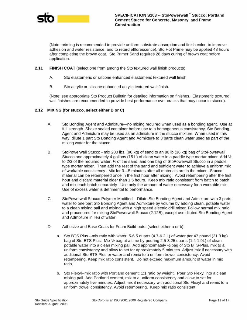
(Note: priming is recommended to provide uniform substrate absorption and finish color, to improve adhesion and water resistance, and to retard efflorescence). Sto Hot Prime may be applied 48 hours after completing the brown coat. Sto Primer Sand requires 28 days curing of brown coat before application.
2.11 FINISH COAT (select one from among the Sto textured wall finish products)
A. Sto elastomeric or silicone enhanced elastomeric textured wall finish
B. Sto acrylic or silicone enhanced acrylic textured wall finish.
(Note: see appropriate Sto Product Bulletin for detailed information on finishes. Elastomeric textured wall finishes are recommended to provide best performance over cracks that may occur in stucco).
2.12 MIXING (for stucco, select either B or C)
A. Sto Bonding Agent and Admixture—no mixing required when used as a bonding agent. Use at full strength. Shake sealed container before use to a homogeneous consistency. Sto Bonding Agent and Admixture may be used as an admixture in the stucco mixture. When used in this way, dilute 1 part Sto Bonding Agent and Admixture to 3 parts clean water used as part of the mixing water for the stucco.
B. StoPowerwall Stucco - mix 200 lbs. (90 kg) of sand to an 80 lb (36 kg) bag of StoPowerwall
Stucco and approximately 4 gallons (15 L) of clean water in a paddle type mortar mixer. Add ½ to 2/3 of the required water, ½ of the sand, and one bag of StoPowerwall Stucco in a paddle type mortar mixer. Then add the rest of the sand and sufficient water to achieve a uniform mix of workable consistency. Mix for 3—5 minutes after all materials are in the mixer. Stucco material can be retempered once in the first hour after mixing. Avoid retempering after the first hour and discard material older than 1.5 hours. Keep mix ratio consistent from batch to batch and mix each batch separately. Use only the amount of water necessary for a workable mix. Use of excess water is detrimental to performance.
C. StoPowerwall Stucco Polymer Modified – Dilute Sto Bonding Agent and Admixture with 3 parts
water to one part Sto Bonding Agent and Admixture by volume by adding clean, potable water to a clean mixing pail and mixing with a high speed electric drill mixer. Follow normal mix ratio and procedures for mixing StoPowerwall Stucco (2.12B), except use diluted Sto Bonding Agent and Admixture in lieu of water.
D. Adhesive and Base Coats for Foam Build-outs: (select either a or b)
a. Sto BTS Plus --mix ratio with water: 5-6.5 quarts (4.7-6.2 L) of water per 47 pound (21.3 kg) bag of Sto-BTS Plus. Mix ½ bag at a time by pouring 2.5-3.25 quarts (1.4-1.9L) of clean potable water into a clean mixing pail. Add approximately ½ bag of Sto BTS-Plus, mix to a uniform consistency and allow to set for approximately 5 minutes. Adjust mix if necessary with additional Sto BTS Plus or water and remix to a uniform trowel consistency. Avoid retempering. Keep mix ratio consistent. Do not exceed maximum amount of water in mix ratio.
b. Sto Flexyl--mix ratio with Portland cement: 1:1 ratio by weight. Pour Sto Flexyl into a clean
mixing pail. Add Portland cement, mix to a uniform consistency and allow to set for approximately five minutes. Adjust mix if necessary with additional Sto Flexyl and remix to a uniform trowel consistency. Avoid retempering. Keep mix ratio consistent.

SPECIFICATION S103 -- StoPowerwall ™ Stucco: Portland Cement Stucco for Concrete, Masonry, and Frame Construction
Sto Guide Specification Sto Corp. is an ISO 9001:2000 Registered Company Page 12 of 17 Revised: August, 2008
E. Primer--mix with a clean, rust-free high speed mixer to a uniform consistency.
F. Finish--mix with a clean, rust-free high speed mixer to a uniform consistency. A small amount of water may be added to adjust workability. Limit addition of water to amount needed to achieve the finish texture.
G. Mix only as much material as can readily be used.
H. Do not use anti-freeze compounds or other additives.
PART 3 EXECUTION 3.01 ACCEPTABLE INSTALLERS
A. Pre-qualify under Quality Assurance requirements of this specification (section 1.07.B). 3.02 EXAMINATION
A. Inspect surfaces for: 1. Contamination⎯algae, chalkiness, dirt, dust, efflorescence, form oil, fungus, grease,
laitance, mildew or other foreign substances. 2. Surface absorption and chalkiness. 3. Cracks⎯measure crack width and record location of cracks. 4. Damage and deterioration. 5. Moisture damage–-record any areas of moisture damage.
B. Inspect sheathing application for compliance with applicable requirement:
1. Exterior Gypsum Sheathing–GA-253 2. Glass Mat Faced Gypsum Sheathing—refer to manufacturer’s instructions. 3. Exterior Grade and Exposure 1 wood based sheathing—APA Engineered Wood
Association E 30.
Note: wood-based sheathing must be gapped 1/8 inch (3mm) at edge and end joints to prevent cracking in the stucco.
C. Report deviations from the requirements of project specifications or other conditions that
might adversely affect the stucco installation to the General Contractor. 3.03 SURFACE PREPARATION
A. Concrete (Cast-in-Place)
1. Provide a surface that is slightly scarified, water absorbent, straight and true to line and plane. Remove form ties and trim projecting concrete so it is even with the plane of the wall. Remove form release agents by washing with a trisodium phosphate detergent and rinsing with clean water. Establish surface profile by sandblasting, waterblasting, wire brushing, chipping or other appropriate means. Remove all dust, dirt, grease, laitance or other bond inhibiting material. Pre-moisten absorbent surfaces with water prior to placement of stucco.
B. Concrete Masonry Units
SPECIFICATION S103 -- StoPowerwall ™ Stucco: Portland Cement Stucco for Concrete, Masonry, and Frame Construction
Sto Guide Specification Sto Corp. is an ISO 9001:2000 Registered Company Page 13 of 17 Revised: August, 2008
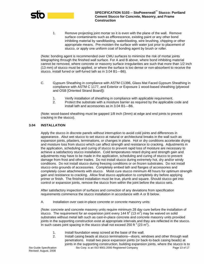
1. Remove projecting joint mortar so it is even with the plane of the wall. Remove surface contaminants such as efflorescence, existing paint or any other bond inhibiting material by sandblasting, waterblasting, wire brushing, chipping or other appropriate means. Pre-moisten the surface with water just prior to placement of stucco, or apply one uniform coat of bonding agent by brush or roller.
(Note: bonding agent is recommended over CMU surfaces to minimize the risk of mortar joints telegraphing through the finished wall surface. For A and B above, where bond inhibiting material cannot be removed, where concrete or masonry surface irregularities are such that more than 1/2 inch (13 mm) of stucco must be applied, or where the surface is too dense or non-absorbent to receive the stucco, install furred or self-furred lath as in 3.04 B1—B6).
C. Gypsum Sheathing in compliance with ASTM C1396, Glass Mat Faced Gypsum Sheathing in compliance with ASTM C 1177, and Exterior or Exposure 1 wood-based sheathing (plywood and OSB [Oriented Strand Board]):
1. Verify installation of sheathing in compliance with applicable requirement. 2. Protect the substrate with a moisture barrier as required by the applicable code and
install lath and accessories as in 3.04 B1—B6.
(Note: wood-based sheathing must be gapped 1/8 inch (3mm) at edge and end joints to prevent cracking in the stucco).
3.04 INSTALLATION
Apply the stucco in discrete panels without interruption to avoid cold joints and differences in appearance. Abut wet stucco to set stucco at natural or architectural breaks in the wall such as expansion joints, pilasters, terminations, or changes in plane. Hot or dry conditions accelerate drying and moisture loss from stucco which can affect strength and resistance to cracking. Adjustments in the application, scheduling and curing of stucco to prevent rapid loss of moisture are necessary to achieve a satisfactory stucco installation. Cold temperatures retard drying and strength gain and adjustments may have to be made in the application, scheduling and curing of stucco to prevent damage from frost and other trades. Do not install stucco during extremely hot, dry and/or windy conditions. Do not install stucco during freezing conditions or on frozen substrates. Do not install stucco onto grounds of accessories. Completely embed lath and flanges of accessories and completely cover attachments with stucco. Moist cure stucco minimum 48 hours for optimum strength gain and resistance to cracking. Allow final stucco application to completely dry before applying primer or finish. The finished installation must be true, plumb and square. Should stucco get into control or expansion joints, remove the stucco from within the joint before the stucco sets.
After satisfactory inspection of surfaces and correction of any deviations from specification requirements commence the stucco installation in accordance with A or B below.
A. Installation over cast-in-place concrete or concrete masonry units:
(Note: concrete and concrete masonry units require minimum 28 day cure before the installation of stucco. The requirement for an expansion joint every 144 ft2 (13 m2) may be waived on solid substrates without metal lath such as cast-in-place concrete and concrete masonry units provided joints in the supporting construction exist at appropriate intervals and they are reflected in the stucco. In such cases joint spacing in the stucco shall not exceed 250 ft 2 (23 m2).
1. Install foundation weep screed at the base of the wall. 2. Install casing beads at stucco terminations—doors, windows and other through wall
penetrations. Install two piece expansion joints (or back-to-back casing beads) at joints in the supporting construction, building expansion joints, where the stucco is to

SPECIFICATION S103 -- StoPowerwall ™ Stucco: Portland Cement Stucco for Concrete, Masonry, and Frame Construction
Sto Guide Specification Sto Corp. is an ISO 9001:2000 Registered Company Page 14 of 17 Revised: August, 2008
be installed over dissimilar construction or substrates, at changes in building height, at floor lines, columns, and cantilevered areas. Install one piece expansion joints at corners of windows, doors and similar through wall penetrations, and every 250 ft2 (23 m2). Install corner bead at outside corners and corner lath at inside corners. Install full accessory pieces where possible and avoid small pieces. Seal adjoining pieces by embedding ends in sealant. Abut horizontal into vertical joint accessories. Attach at no more than 7 inches (178 mm) on center into concrete/masonry with appropriate fasteners.
3. Pre-moisten concrete masonry units and absorbent concrete prior to the placement of stucco (unless bonding agent has been applied to the CMU surface).
4. Scratch Coat: apply the stucco with sufficient pressure to ensure intimate contact with the substrate and complete coverage to an approximate thickness of 1/4 inch (6 mm). Score the stucco upon completion of each panel in preparation for a second coat. Score horizontally.
5. Brown Coat: as soon as the first coat is firm enough to receive the second coat without damage, apply the second coat. Alternatively, moist cure the first coat up to 48 hours and dampen the scratched surface with water immediately before applying the second coat. Apply the second coat with sufficient pressure to ensure intimate contact with the first coat to an approximate thickness of 1/8 or 1/4 inch (3 or 6 mm) and as needed to bring the stucco to the desired thickness. Use a rod or straight edge to bring the surface to a true, even plane. Fill depressions in plane with stucco. Final thickness of stucco shall not exceed ½ inch (13 mm).
6. After the stucco has lost sufficient moisture so that the surface sheen has disappeared, float the surface lightly with a darby or wood float to densify the surface and to provide a smooth, even surface. Float before the stucco becomes so rigid that it cannot be moved beneath the float.
7. Moist cure after the stucco has set by lightly fogging the surface for at least 48 hours. Fog as frequently as required during the 48 hour period to prevent loss of moisture from the stucco. Avoid eroding the stucco surface with excess moisture. If relative humidity exceeds 75% the frequency of moist-curing can be diminished.
(*Note: for one coat installation of stucco follow the procedure described above, except apply the stucco in one coat up to ½ inch (13 mm) thickness, and eliminate scoring and the application of brown coat).
B. Installation over frame construction with sheathing:
1. Weep Screed Installation
a. Install foundation weep screed at the base of the wall securely to framing with the appropriate fastener. Locate foundation weep screed so that it overlaps the joint between the foundation and framing by a minimum of 1inch (25 mm). Locate the foundation weep screed minimum 4 inches (100 mm) above earth grade, 2 inches (51 mm) above finished grade (paved surfaces, for example).
2. Weather Protection
a. Protect sills of rough openings with barrier membrane. b. Apply moisture barrier in compliance with the applicable building code. Wrap
paper into rough opening and lap over barrier membrane at jambs. Lap paper over foundation weep screed attachment flange and window/door head flashings. Refer to Sto Details.
(Note: code requirements for weather protection vary. Always consult the applicable code and the manufacturer’s code compliance report. Typically building paper in compliance with the code is attached directly to sheathing and lapped shingle style, upper courses over lower courses, by minimum 2 inches (51 mm), with vertical laps of minimum 6 inches (150 mm). Courses are staggered

SPECIFICATION S103 -- StoPowerwall ™ Stucco: Portland Cement Stucco for Concrete, Masonry, and Frame Construction
Sto Guide Specification Sto Corp. is an ISO 9001:2000 Registered Company Page 15 of 17 Revised: August, 2008
so that vertical joints do not align. The IBC and IRC require two layers of building paper over wood-based sheathing. If paper-backed lath is used, the water resistant backing serves as the weather protection or as one of the two layers of paper required over wood-based sheathing. Care must be taken to prevent tears in the paper and to limit penetrations to only those required for attachment. Flashing must be in place and properly integrated with the moisture barrier at sills, above windows and doors, decks and at roof/wall intersections such that water is directed to the exterior).
3. Casing Bead and Expansion Joint Installation
a. Install casing beads at stucco terminations—doors, windows and other through wall penetrations. Install expansion joints (or back-to-back casing beads) at building expansion joints, where the stucco is to be installed over dissimilar construction or substrates, at changes in building height, at floor lines, columns, and cantilevered areas. Install one piece expansion joints at corners of windows, doors, and similar through wall penetrations, and every 144 ft2 (13 m2). Install full accessory pieces where possible and avoid small pieces. Seal adjoining pieces by embedding ends in sealant. Abut horizontal into vertical joint accessories. Attach at no more than 7 inches (178 mm) into framing with appropriate fasteners.
Note: refer to architectural drawings for joint locations and accessory type. Moisture protection must be continuous behind joints and accessories.
4. Lath Installation
a. Diamond Mesh Metal Lath i. General--install metal lath with the long dimension at right angles to structural
framing. Terminate lath at expansion joints. Do no install continuously beneath joints.
ii. Seams/Overlaps--overlap side seams minimum 1/2 inch (13 mm) and end seams minimum 1 inch (25 mm). Stagger end seams. Overlap casing beads and expansion joints minimum 1 inch (25 mm) over narrow wing accessories, minimum 2 inches (51 mm) over expanded flange accessories. Do not install lath continuously beneath expansion joints.
iii. Attachment--fasten securely through sheathing into structural framing at 7 inches (178 mm) on center maximum vertically and 16 inches (406 mm) on center horizontally*. Wire tie at no more than 9 inches (225 mm) on center at: side laps, accessory overlaps, and where end laps occur between supports.
b. Woven wire fabric lath—follow installation as for metal lath except overlap all seams by one mesh minimum.
c. Paper-backed lath—follow installation as for metal lath. Lap lath over lath, not paper to lath overlap. For horizontal overlaps the paper backing must lap shingle style behind the lath to lath overlap.
(*Note: the type fastener selected, its layout and pullout or withdrawal value from the supporting construction must be verified and approved by the project engineer/architect with respect to design wind load and local building code requirements).
5. One Piece Expansion Joint Installation
a. Install one piece expansion joints over lath at through wall penetrations, for example, above and below doors or windows (unless another type of expansion joint is already provided at these locations or one piece expansion joints are already provided as in 3.04 B3a). Install one piece expansion joints over lath every 144 ft2 (13 m2) (unless already provided as in 3.04 B3a.). Wire tie one piece expansion joints to lath at no more than 7 inches (178 mm) on center. Make certain lath is discontinuous beneath joints.
6. Inside and Outside Corners
SPECIFICATION S103 -- StoPowerwall ™ Stucco: Portland Cement Stucco for Concrete, Masonry, and Frame Construction
Sto Guide Specification Sto Corp. is an ISO 9001:2000 Registered Company Page 16 of 17 Revised: August, 2008
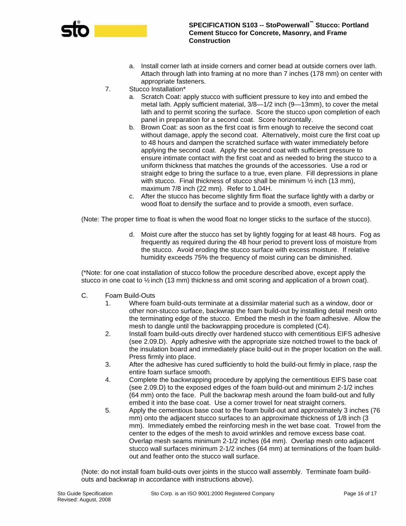
a. Install corner lath at inside corners and corner bead at outside corners over lath. Attach through lath into framing at no more than 7 inches (178 mm) on center with appropriate fasteners.
7. Stucco Installation* a. Scratch Coat: apply stucco with sufficient pressure to key into and embed the
metal lath. Apply sufficient material, 3/8—1/2 inch (9—13mm), to cover the metal lath and to permit scoring the surface. Score the stucco upon completion of each panel in preparation for a second coat. Score horizontally.
b. Brown Coat: as soon as the first coat is firm enough to receive the second coat without damage, apply the second coat. Alternatively, moist cure the first coat up to 48 hours and dampen the scratched surface with water immediately before applying the second coat. Apply the second coat with sufficient pressure to ensure intimate contact with the first coat and as needed to bring the stucco to a uniform thickness that matches the grounds of the accessories. Use a rod or straight edge to bring the surface to a true, even plane. Fill depressions in plane with stucco. Final thickness of stucco shall be minimum ½ inch (13 mm), maximum 7/8 inch (22 mm). Refer to 1.04H.
c. After the stucco has become slightly firm float the surface lightly with a darby or wood float to densify the surface and to provide a smooth, even surface.
(Note: The proper time to float is when the wood float no longer sticks to the surface of the stucco).
d. Moist cure after the stucco has set by lightly fogging for at least 48 hours. Fog as
frequently as required during the 48 hour period to prevent loss of moisture from the stucco. Avoid eroding the stucco surface with excess moisture. If relative humidity exceeds 75% the frequency of moist curing can be diminished.
(*Note: for one coat installation of stucco follow the procedure described above, except apply the stucco in one coat to ½ inch (13 mm) thickness and omit scoring and application of a brown coat).
C. Foam Build-Outs
1. Where foam build-outs terminate at a dissimilar material such as a window, door or other non-stucco surface, backwrap the foam build-out by installing detail mesh onto the terminating edge of the stucco. Embed the mesh in the foam adhesive. Allow the mesh to dangle until the backwrapping procedure is completed (C4).
2. Install foam build-outs directly over hardened stucco with cementitious EIFS adhesive (see 2.09.D). Apply adhesive with the appropriate size notched trowel to the back of the insulation board and immediately place build-out in the proper location on the wall. Press firmly into place.
3. After the adhesive has cured sufficiently to hold the build-out firmly in place, rasp the entire foam surface smooth.
4. Complete the backwrapping procedure by applying the cementitious EIFS base coat (see 2.09.D) to the exposed edges of the foam build-out and minimum 2-1/2 inches (64 mm) onto the face. Pull the backwrap mesh around the foam build-out and fully embed it into the base coat. Use a corner trowel for neat straight corners.
5. Apply the cementious base coat to the foam build-out and approximately 3 inches (76 mm) onto the adjacent stucco surfaces to an approximate thickness of 1/8 inch (3 mm). Immediately embed the reinforcing mesh in the wet base coat. Trowel from the center to the edges of the mesh to avoid wrinkles and remove excess base coat. Overlap mesh seams minimum 2-1/2 inches (64 mm). Overlap mesh onto adjacent stucco wall surfaces minimum 2-1/2 inches (64 mm) at terminations of the foam build-out and feather onto the stucco wall surface.
(Note: do not install foam build-outs over joints in the stucco wall assembly. Terminate foam build-outs and backwrap in accordance with instructions above).

SPECIFICATION S103 -- StoPowerwall ™ Stucco: Portland Cement Stucco for Concrete, Masonry, and Frame Construction
Sto Guide Specification Sto Corp. is an ISO 9001:2000 Registered Company Page 17 of 17 Revised: August, 2008
D. Primer Installation
1. Sto Hot Prime—Moist cure stucco for a minimum of 48 hours. Apply primer evenly with brush, roller or proper spray equipment over the clean, dry stucco and foam build-outs, and allow to dry before applying finish.
2. Sto Primer Sand—Moist cure stucco for a minimum of 48 hours. Wait until stucco is 28 days old or the pH level of the surface is below 10 before applying primer and allow to dry before applying finish.
E. Finish Installation
1. Apply finish to primed stucco and foam build-outs when dry. Apply finish by spraying or troweling with a stainless steel trowel, depending on the finish specified. Follow these general rules for application of finish: a. Avoid application in direct sunlight. b. Apply finish in a continuous application, and work a wet edge towards the
unfinished wall area. Work to an architectural break in the wall before stopping to avoid cold joints.
c. Weather conditions affect application and drying time. Hot or dry conditions limit working time and accelerate drying. Adjustments in the scheduling of work may be required to achieve desired results; cool or damp conditions extend working time and retard drying and may require added measures of protection against wind, dust, dirt, rain and freezing. Adjust work schedule and provide protection.
d. Float "R" (rilled texture) finishes with a plastic float to achieve their rilled texture. e. Do not install separate batches of finish side-by-side. f. Do not apply finish into or over joints or accessories. Apply finish to outside face
of wall only. g. Do not apply finish over irregular or unprepared surfaces, or surfaces not in
compliance with the requirements of the project specifications. 3.05 PROTECTION
A. Provide protection of installed materials from water infiltration into or behind them.
B. Provide protection of installed stucco from dust, dirt, precipitation, and freezing.
C. Provide protection of installed primer and finish from dust, dirt, precipitation, freezing and continuous high humidity until fully dry.
ATTENTION
Sto products are intended for use by qualified professional contractors, not consumers, as a component of a larger construction assembly as specified by a qualified design professional, general contractor or builder. They should be installed in accordance with those specifications and Sto’s instructions. Sto Corp. disclaims all, and assumes no, liability for on-site inspections, for its products applied improperly, or by unqualified persons or entities, or as part of an improperly designed or constructed building, for the nonperformance of adjacent building components or assemblies, or for other construction activities beyond Sto’s control. Improper use of Sto products or use as part of an improperly designed or constructed larger assembly or building may result in serious damage to Sto products, and to the structure of the building or its components. STO CORP. DISCLAIMS ALL WARRANTIES EXPRESS OR IMPLIED EXCEPT FOR EXPLICIT LIMITED WRITTEN WARRANTIES ISSUED TO AND ACCEPTED BY BUILDING OWNERS IN ACCORDANCE WITH STO’S WARRANTY PROGRAMS WHICH ARE SUBJ ECT TO CHANGE FROM TIME TO TIME. For the fullest, most current information on proper application, clean-up, mixing and other specifications and warranties, cautions and disclaimers, please refer to the Sto Corp. website, www.stocorp.com.