Embed Size (px)
Citation preview

hpGEM – A Software Framework forDiscontinuous Galerkin Finite Element Methods
LARS PESCH, ALEXANDER BELL, HENK SOLLIE, VIJAYA R. AMBATI,
ONNO BOKHOVE, and JAAP J.W. VAN DER VEGT
hpGEM, a novel framework for the implementation of discontinuous Galerkin finite element meth-ods (FEMs), is described. We present data structures and methods that are common for many(discontinuous) FEMs and show how we have implemented the components as an object-orientedframework. This framework facilitates and accelerates the implementation of finite element pro-grams, the assessment of algorithms, and their application to real-world problems. The articledocuments the status of the framework, exemplifies aspects of its philosophy and design, anddemonstrates the feasibility of the approach with several application examples.
Categories and Subject Descriptors: D.3.2 [Programming Languages]: Language Classifications–C++; G.1.8[Numerical Analysis]: Partial Differential Equations–Finite element methods; G.4 [Mathematical Software]:Algorithm design and analysis
General Terms: Algorithms, Design
Additional Key Words and Phrases: Discontinuous Galerkin methods, PDE, unstructured mesh,object-oriented programming
1. INTRODUCTION
Finite element methods are a field of active research in applied mathematics. In recentyears, new and rapid developments have taken place, in particular in the field of discontin-uous Galerkin (DG) methods. This type of finite element method (FEM) is different from“classical” ones in that functions are allowed to be discontinuous across the boundariesbetween elements. The advantages of the resulting discretizations include the possibilityto use basis functions with different polynomial order in different elements (p-adaptation),the ease of incorporating mesh refinement (h-adaptation) and unstructured meshes, and theincrease in locality of the discretization, which is of particular interest for parallel comput-ing. More information about discontinuous Galerkin methods, their properties and theiradvantages over classical FEMs and other methods can be found in Section 2. For themoment we can return to our consideration of FEMs in general.
Typically, the design of finite element (FE) algorithms starts with the formal definitionof the method by deriving a weak formulation of the system of partial differential equationsand choosing basis functions to discretize the function spaces. Properties of the method canthen be examined and, given satisfying results, the next step will be to use it for solving the
Authors’ address: University of Twente, Dept. of Applied Mathematics, P.O. Box 217, 7500 AE Enschede, TheNetherlands.Permission to make digital/hard copy of all or part of this material without fee for personal or classroom useprovided that the copies are not made or distributed for profit or commercial advantage, the ACM copyright/servernotice, the title of the publication, and its date appear, and notice is given that copying is by permission of theACM, Inc. To copy otherwise, to republish, to post on servers, or to redistribute to lists requires prior specificpermission and/or a fee.c© 2006 ACM 0098-3500/2006/1200-0001 $5.00
ACM Transactions on Mathematical Software, Vol. V, No. N, December 2006, Pages 1–22.

2 · L. Pesch et al.
target problem numerically. For that purpose, the developed algorithm has to be translatedinto a computer program. A correct implementation not only gives a numerical solutionbut can also be used to determine additional properties of the algorithm, like approximationorders, iterative convergence rates, and computational costs.
The definition and analysis of a FEM is a complicated exerciseand relies on the math-ematical skills of the developer. In this article, we address the following step, the imple-mentation as a computer program, which we consider an equally complex task based onour experience with diverse mathematical problems, algorithms, and programming lan-guages. Additional complications arise from recent developments on the computationalside, which allow the numerical solution of many real-worldproblems on increasinglypowerful computing systems. On the other hand, the utilization of such systems poses ad-ditional requirements on the implementation—parallelization is a keyword hinting at theadded complexity. At this point it is tenable that the transformation of a mathematicalmodel into a capable computer code is a task that goes far beyond the abilities of a single,say mathematically trained, person. Apart from the skill constraint, developments are alsolimited by the amount of work that an individual can accomplish on the timescale of atypical research project. The logical consequence is that efforts have to be joined to reachthe forefront of current developments in applied mathematics.
A related difficulty regarding the efficiency of the software development process is tomaintain productivity over more than a single project. Having invested in software designand development as described above, the effort would be wasted if there was no possibilityto reuse the result—i.e. the software artifacts—for applying new algorithms to the same orother problems. For that reason it is important that software is built in a modular and exten-sible way, representing general concepts and separating the application-related items fromabstract mathematical parts, and those in turn from underlying computer-scientific details.It is therefore a prerequisite for our work to decompose FEMsinto recurring componentsand tasks, and additional parts, which are specific to individual methods.
The foundation of the work presented here is that those partsthat are the same in manyFEM implementations constitute a relatively large fraction. Examples are the representa-tion of the geometric mesh of the domain, the mathematical definition of the finite elements(shape, basis functions, degrees of freedom), and the assembly and solution of systems ofequations. The crux is that typically these parts are ‘reinvented’ and reimplemented byindividuals when starting from scratch, incurring a large overhead in development timeand—more importantly—the potential of introducing codingerrors. That is where ourcurrent work comes in: it provides well-tested data structures and methods on which thespecific FE application can build, thus cutting short the implementation time and reducingthe danger of introducing mistakes.
Naturally, the decomposition of FEMs will also reveal tasksfor which highly developed,tested and established solutions are available, e.g. from computer science (data containersand search algorithms) or numerical linear algebra (solvers for systems of equations). It isnot so much the question ofwhetherto use them but ratherhow to do it. Here the benefitof our software environment is that it provides access to various packages, which enhanceits functionality and capabilities.
Given hpGEM, the finite element software framework we describe here [hpGEM], itremains to the applying scientist—starting from a correct mathematical formulation of thediscrete problem—to a) assemble the provided components ina correct and efficient way,
ACM Transactions on Mathematical Software, Vol. V, No. N, December 2006.

hpGEM – A software framework for discontinuous Galerkin finite element methods · 3
and b) add whatever is special or unique to a considered problem or algorithm. Obviouslyadditions to the framework are possible when sufficient generality and usefulness havebeen shown.
This article is structured as follows: a brief introductionto DG FEMs, their propertiesand differences to other FEMs is presented in Section 2. In Section 3,we will detail therequirements we formulated for the software framework and compare these with some ex-isting FE packages. Topics like the choice of the programming model, the implementationlanguage and software engineering aspects are covered in Section 4. Section 5 containsseveral examples of how a software framework can be designedto reflect the generic char-acter of finite element algorithm components. Some sample applications to solve physicalproblems are presented in Section 6. In Section 7, we summarize our work, draw conclu-sions and give an overview of future activities.
2. DISCONTINUOUS GALERKIN FINITE ELEMENT METHODS
Finite element methods constitute a theoretically well-founded approach to discretize sys-tems of partial differential equations (PDEs) and are used to solve numerous problemsarising from applications in physics and technology. A key feature of many problems arephenomena which occur at very different length scales but strongly interact with each other.Examples are thin boundary layers and moving interfaces in fluid flow, chemical reactionsat surfaces, and flames in combustion. A simulation technique is required with adjustableaccuracy to efficiently capture the relevant scales in these multi-scale problems. Adapta-tion can either locally refine the mesh (h-refinement) or adjust the polynomial order of thesolution representation (p-refinement). The combination of these techniques is calledhp-adaptation and is a promising approach to obtain highly efficient numerical schemes for alarge variety of multi-scale problems.
The use ofhp-adaptation is, however, non-trivial to implement in standard finite elementmethods. In these methods, serious problems occur when two or more elements connect toa face of another element after local mesh refinement (hanging nodes) or if the polynomialbasis functions in two connecting elements are of different order afterp-adaptation.1 Asmentioned in the introduction, discontinuous Galerkin finite element methods pose no extraproblems regardinghp-adaptation2 and achieve higher order accuracy even on unstructuredmeshes. This is possible because the support of each basis function contains only oneelement, cf. Figure 1, and a coupling to the neighboring elements exists only in the weaksense, as we shall see later. The locality of the basis functions not only allows to vary thenumber of basis functions (the approximation order) individually for each element, but alsoreduces the coupling in the discretization: information isexchanged exclusively betweenneighboring elements by fluxes (hyperbolic PDEs) or other face-based operators (ellipticPDEs). This is beneficial forhp-adaptation as well as for parallel computing because itminimizes the amount of data communication. General surveys of discontinuous Galerkinfinite element methods can be found in [Cockburn 1999; Cockburn et al. 2000; Cockburnand Shu 2001; Arnold et al. 2002]. In the remainder of this section we will give brieflyintroduce a DG method for conservation laws.
We consider a non-linear scalar conservation law, which is asimplified model for a large
1Different zones have to be connected by special elements complicating the software.2hp-adaptation is, in fact, so central to the development of both discontinuous Galerkin methods and our softwareframework thathp became part of the namehpGEM.
ACM Transactions on Mathematical Software, Vol. V, No. N, December 2006.

4 · L. Pesch et al.
a) continuous FEM: nodal basis functions b) discontinuous Galerkin FEM: basis functions per element
slopemean
Ei EiEi Ei+1
φ0
φ1
φi
xi−1 xi−1xi−1 xi xixi xi+1
Fig. 1. Nodal basis functions of continuous FEMs (left) and element-based basis functions of DG methods(right). For continuous methods the shown basis (one degreeof freedom in every mesh node) is the lowestpossible approximation order. For the discontinuous Galerkin method, a linear representation per elementEi
can be obtained by using the two basis functions for the element mean and slope,φ0 andφ1, respectively. Thisrepresentation could be reduced by using justφ0 for the element mean, corresponding to a finite volume scheme.
xi−1 xi xi+1 xi−1 xi xi+1
Fig. 2. Representation of a function by the above bases for continuous (left) and discontinuous (right) elements.
class of physical problems and contains many of their characteristic features. The scalarconservation law in a spatial domainΩ ⊂ 2 and at timet ∈ [ts, te] is
∂u∂t+ ∇ · F (u) = 0, in (ts, te) ×Ω , (1)
with initial condition u(t = ts, x) = u0(x), ∀ x = (x, y)⊺ ∈ Ω, and boundary conditionu(t, x) = g(x) at Γ ⊂ ∂Ω for all t ∈ [ts, te]. Here, u is a conserved scalar quantity,F theflux function,g a prescribed boundary function, and∇ = ( ∂
∂x,∂∂y)⊺, where a superscript (·)⊺
denotes the transpose of a vector. Examples for flux functionsF are the (linear) advectionflux, F (u) = a u, and the flux for the inviscid Burgers equation,F (u) = u2/2.
The DG discretization is obtained by the following steps. First, we define a discretespaceVh without continuity requirement at element boundaries. Basis functions for Vh
can be chosen such that they are nonzero only in one element rather than in all elementsconnected to a node, as would be the case for the nodal basis functions of classical FEMs.In Figure 1, we contrast nodal basis functions of a continuous FEM with the element-wise defined polynomial basis functionsφi of a discontinuous Galerkin method in onedimension. Possible representations of a function in the discrete spaces spanned by thesesets of basis functions are given in Figure 2.Next, we multiply Equation 1 with an arbitrary test functionv, integrate over each element,and sum over all elements. Finally, the solutionu and the test functionv are restricted tothe spaceVh, and denoted byuh andvh, respectively. The weak formulation of (1) is thengiven by: Find auh ∈ Vh, such that for allvh ∈ Vh the following relation is satisfied:
Ne∑
i=1
∂
∂t
∫
Ei
uhvhdE−∫
Ei
∇vh · F (uh)dE+∫
∂Ei
vh n · F (u−h , u+h)ds
= 0 . (2)
Here,Ei denotes theith element in a finite element mesh withNe elements. The boundary of
ACM Transactions on Mathematical Software, Vol. V, No. N, December 2006.
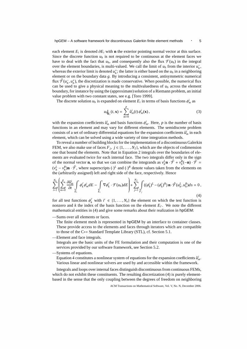
hpGEM – A software framework for discontinuous Galerkin finite element methods · 5
each elementEi is denoted∂Ei with n the exterior pointing normal vector at this surface.Since the discrete functionuh is not required to be continuous at the element faces wehave to deal with the fact thatuh, and consequently also the fluxF (uh) in the integralover the element boundaries, is multi-valued. We call the limit of uh from the interioru−h ,whereas the exterior limit is denotedu+h ; the latter is either based on theuh in a neighboringelement or on the boundary datag. By introducing a consistent, antisymmetric numericalflux F (u−h , u
+h ), the discretization is made conservative. When possible,the numerical flux
can be used to give a physical meaning to the multivaluednessof uh across the elementboundary, for instance by using the (approximate) solutionof a Riemann problem, an initialvalue problem with two constant states, see e.g. [Toro 1999].
The discrete solutionuh is expanded on elementEi in terms of basis functionsφim as
uhEi(t, x) =
p∑
m=0
uim(t) φi
m(x) , (3)
with the expansion coefficientsuim and basis functionsφi
m. Here,p is the number of basisfunctions in an element and may vary for different elements. The semidiscrete problemconsists of a set of ordinary differential equations for the expansion coefficientsui
m in eachelement, which can be solved using a wide variety of time integration methods.
To reveal a number of building blocks for the implementationof a discontinuous GalerkinFEM, we also make use of facesF j , j ∈ 1, . . . ,Nf , which are the objects of codimensionone that bound the elements. Note that in Equation 2 integrals over the boundaries of ele-ments are evaluated twice for each internal face. The two integrals differ only in the signof the normal vectorn, so that we can combine the integrands asvL
hn · F + vRh(−n) · F =
(vLh − vR
h)n · F , where superscripts (·)L and (·)R denote values taken from the elements onthe (arbitrarily assigned) left and right side of the face, respectively. Hence
Ne∑
i=1
p∑
m=0
∂uim
∂t
∫
Ei
φi′kφ
imdE−
∫
Ei
∇φi′k · F (uh)dE
+
Nf∑
j=1
∫
F j
((φik)
L− (φik)
R) n · F (uLh, u
Rh)ds= 0 ,
(4)for all test functionsφi′
k with i′ ∈ 1, . . . ,Ne the element on which the test function isnonzero andk the index of the basis function on the elementEi′ . We note the differentmathematical entities in (4) and give some remarks about their realization inhpGEM:
—Sums over all elements or faces.The finite element mesh is represented inhpGEM by an interface to container classes.These provide access to the elements and faces through iterators which are compatibleto those of the C++ Standard Template Library (STL), cf. Section 5.1.
—Element and face integrals.Integrals are the basic units of the FE formulation and theircomputation is one of theservices provided by our software framework, see Section 5.2.
—Systems of equations.Equation 4 constitutes a nonlinear system of equations for the expansion coefficientsui
m.Various linear and nonlinear solvers are used by and accessible within the framework.
Integrals and loops over internal faces distinguish discontinuous from continuous FEMs,which do not exhibit these constituents. The resulting discretization (4) is purely element-based in the sense that the only coupling between the degreesof freedom on neighboring
ACM Transactions on Mathematical Software, Vol. V, No. N, December 2006.

6 · L. Pesch et al.
elements is through the numerical fluxF (u−h , u+h). This allows to use different polynomial
order foruh in the two elements connected by the faceF j .The above formulation has been the foundation for our previous work on the Euler equa-
tions [van der Vegt and van der Ven 1998; 2002; van der Ven and van der Vegt 2002; van derVen et al. 2003] and shallow water equations [Bokhove 2005].Discontinuous Galerkinmethods can also be applied to elliptic equations, an example can be found in [van derVegt and Tomar 2005]. Combining the hyperbolic and ellipticparts allows, for instance,to numerically solve mixed-type equations like (nonlinear) advection-diffusion [Sudirhamet al. 2006; Bokhove et al. 2005] and the Navier-Stokes equations [van der Ven et al. 2005;Klaij et al. 2006a; 2006b].
3. REQUIREMENTS ANALYSIS AND RELATED WORK
Looking at the finite element software landscape there are many existing tools, which wecannot review extensively here. From code fragments developed by single users to com-mercial systems there is a wide spectrum of artifacts available that may allow to implementa solution scheme. To establish why we have started another development we consider theessential requirements for our software; these include:
—Ability to use discontinuous Galerkin methods.These methods are the focus of our research. From Section 2 itfollows that some aspectsmake DG methods different from continuous finite element methods. In particulartheuse of face-based data structures for the computation of (numerical) fluxes in hyperbolicsystems like (4) is different from classical FEMs. On the other hand, some of thesedifferences can be taken advantage of, in particular in the form of increased concurrencyin the computation of the element-based discretization.
—General types of elements ind, d = 1, . . . , 4.Another advantage of DG methods is their flexibility with respect to the geometric shapeof the elements. For two-dimensional meshes, mixtures of triangles and quadrilateralscan be as easily accommodated as three-dimensional meshes with tetrahedra, pyramids,triangular prisms, and hexahedra. For so-called space-time FEMs, we have to extend theelements with an extra dimension for time, so for three-dimensional space the elementsbecome four-dimensional.
—Dimension-independence of the code.For many FE algorithms the mathematical formulation is independent of the dimensionof the problem. To a large degree this property can be conserved by the software envi-ronment. Application codes developed in a two-dimensionalsetting can frequently beused for three-dimensional computations by changing a (C++-template-) parameter, ifthe user’s code allows this, too.
—Easy and fast generation of applications.When testing an algorithm the first question is how long it will take to correctly im-plement it. Hence it is important that provided components are easy to use and well-documented.
—Parallelism handled internally.While parallel computing is of prime importance for many relevant physical applica-tions, it is a corollary of the previous item that the exploitof parallel computation strate-gies should be as far as possible handled internally, so thata user program can remain
ACM Transactions on Mathematical Software, Vol. V, No. N, December 2006.

hpGEM – A software framework for discontinuous Galerkin finite element methods · 7
largely unchanged for serial and parallel processing. To what extent this can be realizedand where the user has to intervene will be described in a follow-up article.
—Enforcement of quality standards.To guarantee a correct and extensible FE framework, we rely on documentation, bothin-code and external, a set of unit tests and separate test applications.
—Access to external software for common tasks.Because we concentrate on FE-related research we make use ofexisting components forthe pre- and post-processing steps, e.g. mesh generation and visualization. Also for taskslike linear algebra, existing high-quality solutions can be employed by the framework ormade accessible to the user.
The above items constitute the most important requirements, yet the result of our search fora matching candidate was that no available solution satisfied our needs. We briefly discussthis conclusion by comparing a few available software packages based on object-orienteddevelopment to the above list; the findings are typical for many FEM software artifacts.
Discontinuous Galerkin methods, being a relatively recenttopic, are not implementedby most FE packages and their special aspects (e.g. face datastructures) are not taken intoaccount. Packages which seem to support discontinuous Galerkin methods are DEAL.II[Bangerth et al. ] and DOLFIN [Hoffman and Logg 2002]. However, the former works onlyon n-cubes, i.e. elements are lines, quadrilaterals, and hexahedra in dimension 1, 2, and 3,respectively. The latter, just like other packages, e.g. ALBERTA [Schmidt and Siebert ],restricts itself to simplices, so that meshes consist of triangular or tetrahedral elements.Mixed meshes are rarely accommodated by existing FE software, possibly because of thecomplications when using continuous FEMs. We could not find any package that offerssupport for space-time discretizations, elements are onlyimplemented for dimensions oneto three. Within these bounds, codes based on DEAL.II or ALBERTA can be dimension-independent for meshes based exclusively onn-cubes or simplices, respectively.
Different philosophies become apparent when it comes to the application program inter-face (API) available to the users of a software framework. Insome packages, high-levelaccess is provided to a degree that modules allow the solution of pre-programmed equa-tions by choosing the geometry, suitable initial and boundary conditions [Hoffman andLogg 2002].
The access to external software in the mentioned packages is—if at all provided—frequently hidden by extensive interfaces. This has the advantage of unified access todifferent packages, which however comes at high development cost and possibly restrictsthe range of usable options of the integrated packages. Remarkably, some FE packagesrely entirely on their own developments regarding linear algebra and equation solvers.
Efforts regarding the quality measures mentioned previously vary; online documentationfor the abovementioned packages is available, sometimes also detailed tutorials, e.g. forDEAL.II, which also seems to be most advanced regarding its test suite.
Apparently, failure to comply with the first two items from our list above lead us toreject many available FE packages. The other topics are moredebatable, but collectivelycan be of equal importance. We will show applications of mixed meshes and dimensionindependent code in the examples in Section 6, which belong to the sample programs help-ing to learn usinghpGEM. Software handling issues will be touched upon in Section 4.3.Regarding the quality and accessibility of the framework, our available documentation is
ACM Transactions on Mathematical Software, Vol. V, No. N, December 2006.

8 · L. Pesch et al.
important, but what we have found even more valuable is that atest-suite is built up with thecode. Currently more than 150 unit tests check the correct working of individual classes,procedures, and collaborative tasks (like computing normal vectors, evaluating integrals).The unit tests can be re-run at any time, so that changes and additions to the frameworkcan immediately be assessed for correctness.
Whenever a complex task (e.g. linear equation solving) is served well by an availableexternal solution we consider using that one rather than to reimplement such features. Thelatter does not seem viable to us for reasons of development overhead and lack of exper-tise; we appreciate the efforts of many groups to provide free, quality, high-performancesoftware.
Regarding the API, it is not the goal ofhpGEM to be a ‘solver’. Rather we intendto serve numerical scientists by providing the concepts that occur in a worked-out weakform, e.g. as identified for Equation 4 in Section 2. Concreteproblems are solved by sampleapplications, but the actualhpGEM framework concentrates on the general building blocks.We believe that this allows us to be least restrictive and most widely applicable.
4. BASIC APPROACH
When dealing with FEMs, an advantageous aspect of their structure is the way in whichmathematical and geometrical concepts emerge and work together. It will be beneficialin several ways to preserve this structure when creating a finite element software environ-ment: first, the accessibility of the software framework forusers with mainly mathematicalbackground knowledge is improved; having worked out a FE formulation in mathematicalterms, the translation into computer code is simplified if the same concepts are used tobuild up the code as for the analytical formulation. Second,software artifacts representingthe general concepts of finite element algorithms will have ahigh potential of reuse. Atypical one-off FE application code tries to use as many simplifications as the structure ofthe problem at hand allows. Consequently, the resulting code does not reflect the abstractmathematical concepts any more. The latter, however, are the general building blocks formany formulations and hence providing them will increase the re-usability. The clear-cutentities in FEMs can be preserved well by an object-oriented(OO) programming model.
4.1 Object-Oriented Development and Programming
The first approaches to object-oriented modeling of systemsdate back to the eighties. Inthe mid-nineties, Rumbaugh’sObject Modeling Technique(OMT) [Rumbaugh et al. 1991]and Booch’sBooch Method(BM) [Booch 1994] were combined resulting in the develop-ment of the Unified Modeling Language (UML), which was accepted as a standard of theObject Management Group in 1997. In 2005, UML evolved to an international standard asISO 19501.
We consider object-oriented development, comprising the modeling and programmingof a system, as the most important advance in software engineering during the last twodecades, clearly going one step further than object-oriented programming alone.
During the development ofhpGEM we use the UML to represent the results from in-dividual phases of the BM: conceptualization (definition ofcore requirements of system),analysis (creation of a model of the system capturing important properties regarding thefunctionality), design (modeling the system architecturein detail: subsystems, first “ob-jects” and their interaction), evolution (translation of into a programming language, doc-umentation), and maintenance (post-production phase: adaptation, extension, bug-fixes).
ACM Transactions on Mathematical Software, Vol. V, No. N, December 2006.

hpGEM – A software framework for discontinuous Galerkin finite element methods · 9
The first two phases have already been addressed in Section 3.Note that the usage ofan object-oriented development model does not require the usage of an object-orientedimplementation language, although such a language clearlysimplifies the implementation.
A disadvantage of the object-oriented approach lies in the runtime overhead that may beincurred by the introduction of higher-level software constructs. Representing the generalconcepts of FEMs within an object-oriented language reduces the possibilities to applystructural, problem-dependent optimization and introduces overhead for the object han-dling. However this effect on the runtime has to be contrasted with the greater ease offamiliarization and development with the software framework. We experience that thetime savings thanks to faster application development outweigh the runtime overhead.
4.2 Programming Language
Having agreed on the development model, the programming language is the next item toselect. In recent years, with the growing acceptance of object-oriented techniques also inthe scientific programming world, C++ has been the language of choice for many develop-ments. Reasons that suggest committing to this language include:
—C++ is not only a full-fledged object-oriented language, but also supports programmingin procedural style and with elementary constructs, like loops. The latter fact is partic-ularly beneficial for scientific computing where the nature and amount of data requiressuch constructs and their execution at close to machine speed. Furthermore the overheadto get users without experience in object-oriented programming started withhpGEM isreduced by the availability of these more traditional concepts.
—C++ enforces strong type checking, which leads to an unambiguous API and enables tofind many logical errors at compile time.
—Aspects of generic programming are included in C++, most notably in the form of tem-plates. In the scientific computing context, templates are also used to improve runtimeperformance, cf. Veldhuizen [1995] for classical examples. We will come back to theusage of templates at the end of this section.
—C++ is a widely available, standardized, well-known, current language. These propertiesmake the language a solid foundation to build on: standard-compliant code is guaranteedto run on a wide range of platforms with several available compilers. Its widespreaduse, not only in scientific computing, means that support forC++ will not cease on theforeseeable timescale of our project, that there are qualified scientists to contribute tothe project, and vice versa that expertise gained in the project is of wider relevance aswell. Last but not least, C++ is one of the most supported languages when it comes totechniques and tools for software engineering. These can significantly contribute to thesuccess of a project; the ways in which we make use of such tools will be described inSection 4.3.
A possible alternative in the language decision would have been Fortran 90, which is stillwidely used for scientific computing. However, Fortran cannot match with C++ on theabove list of qualities. In the versions for which compilersare currently available, Fortranincompletely supports object-oriented programming and lacks some more evolved object-oriented features of C++ (e.g. multiple inheritance). The basic data type of Fortran(onwhich it is admittedly outperforming most other languages)is the array, but less structured
ACM Transactions on Mathematical Software, Vol. V, No. N, December 2006.

10 · L. Pesch et al.
types as they are readily provided by the C++-Standard Template Library (STL) containersare not offered, and generic programming support as through C++-templates is not presentin the language. Obviously it would not be necessary to limitoneself to a single program-ming language, as linking object files generated from several languages is possible. Whilewe may use external software packages programmed in other languages, for the develop-ment ofhpGEM itself, we have chosen to restrict ourselves to C++, as doing otherwisewould potentially decrease portability and increase complexity for the developers.
Of course, choosing C++means making a compromise that includes disadvantages, too.The absence of many services and data structures (like arrays) from the language is ob-structive and has to be compensated by libraries. This fact together with the inclusionmodel for header files, leads to increased compilation time overhead. With the adventof relevant libraries and the increased computer speed these matters tend to become lessinfluential, but that cannot be said for the compile times of code that relies heavily on tem-plates. As mentioned above, templates are used frequently not only to achieve generalitythrough static polymorphism but also to improve performance through compile time codeexpansion. While the C++ standard includes explicit instantiation as a means to avoid theoverhead of the inclusion model for template definitions, this can most frequently not beused for the purposes above because the template arguments are not determined by thelibrary but rather by the user’s code. As a simple example, the class template
template <DimType dim> class PhysSpacePoint <dim>;
is suitable for explicit instantiation since we know that for all our applications the param-eterdim, which gives the dimension of the physical problem space, isrestricted to therange 1, . . . , 4. On the other hand, a construct like
template <class UserData > class DataOnElements ;
cannot be instantiated at the build time of thehpGEM library, as its argument, namelythe class that includes all the data that is stored for each element, is completely problemdependent and hence given by the user.
The latter case is, unfortunately, far more typical of our framework’s code, which reliesheavily on templates; furthermore, experience from large projects [Vandevoorde and Jo-suttis 2003] suggests that explicit instantiation becomeshard to manage, so that up to nowwe have refrained from using it and put up with the longer compilation times.
An aspect that should be mentioned—though it concerns the object-oriented approachrather than the choice of C++ as the programming language—is that thinking in an object-oriented way is a skill that requires learning and experience. It often takes considerabletime to adapt new users to this programming and thinking style as it is fundamentallydifferent from traditional programming paradigms frequently taught to students, even ifC++ is used for that purpose. Hence the education of students andresearchers with regardto C++, object-oriented software development, andhpGEM itself plays an important rolefor the future prospects of the framework.
4.3 Software Engineering Aspects
Having decided to apply an object-oriented software development approach we looked for(software) tools to support in the object-oriented process, cf. Section 4. We will focus on
ACM Transactions on Mathematical Software, Vol. V, No. N, December 2006.

hpGEM – A software framework for discontinuous Galerkin finite element methods · 11
the tools used in the design and evolution phases of the object-oriented macro process inthe following paragraphs.
Design. We have used UML [Booch et al. 1999] class, object, and sequence diagramsto specify the requirements and capabilities of the framework. The diagrams also serve asbasis for the documentation, cf. Section 5.3 for an example.
Evolution. During the evolution phase we continue to use UML tools to reflect changesand extensions to the design. Further, we rely on the classical version management [CVS]and build [GNU make] tools. To guarantee portability and code quality we buildhpGEMusing Gnu and Intel C++ compilers for 32 and 64 bit architectures. Documentation isan integral part of thehpGEM development; in addition to an introductory document fornew users, the source code is documented using the Doxygen documentation generator[Doxygen] which generates either online-browsable documentation in HTML, or an offlinereference manual in LATEX from documented source files. To ensure that components ofthehpGEM framework still meet their specification in the course of ongoing development,we test individual components, mostly on class level but also the collaboration betweenclasses, by applying so called unit tests. To support the development of unit tests we usethe CppUnit library [CppUnit].
5. DESIGN EXAMPLES
5.1 Mesh Interface
To apply a FE method to solve a set of PDEs, the domainΩ is discretized with a mesh thatsubdividesΩ into a number of simple shapes of suitably small size. On these elements,basis functions and other mathematical entities are defined, cf. Section 2. The setup of sucha mesh is itself a complex task, but this step is hardly connected to the equations solvedor the FE method.hpGEM encapsulates mesh setup as a complete service provided bythe framework. Within a few commands that concern the originand type, the user obtainsthe mesh and the framework is ready to work with it. Similar services are provided byother FE packages, as described in Section 3, buthpGEM differs from them in that it takesdimension-independent programming to the full, even on unstructured meshes. Based onthe value of the dimension parameterdim, the commands
Mesh<dim> theMesh;
CentaurMeshFileReader <dim> Reader("mesh.hyb", theMesh);
will read the filemesh.hyb generated by the Centaur mesh generator [Centaursoft 2005],in particular unstructured meshes with mixtures of the possible element geometries: tri-angles and quadrilaterals in two-dimensional meshes and tetrahedra, pyramids, triangularprisms, and hexahedra in three-dimensional meshes. The elements and faces, includingthe appropriate geometry description, consisting of a reference geometry, the physical co-ordinates and a corresponding mapping, are generated automatically by suitable factorymethods, cf. Gamma et al. [1994]. Note that the boundary faces are typically provided bythe mesh generator. On the other hand, the internal faces, which are required by DG FEMs,are not. HencehpGEM provides a general algorithm to generate them.
All information ends up in theMesh class, whose most prominent task is to provide STL-compatible iterators to the element and face containers. Since most meshes in practiceare unstructured (i.e. there is no global rule to identify neighbors; hence neighborship
ACM Transactions on Mathematical Software, Vol. V, No. N, December 2006.

12 · L. Pesch et al.
information has to be stored locally, for DG algorithms typically on the face) we do notprovide other access than iterators. Consequently, a rectangular mesh on the unit squaregenerated with thehpGEM classRectangularMeshGenerator by
PhysSpacePoint <2> p1; p1[0] = p1[1] = 0.; // lower left
PhysSpacePoint <2> p2; p2[0] = p2[1] = 1.; // upper right
unsigned int nrOfEl[] = 8, 8 ; // 8x8 elements
RectangularMeshGenerator <2> rmg(p1, p2, nrOfEl , theMesh);
will not have access by element coordinates(i,j). Here again we prefer the generality ofthe approach with iterators: by exchanging the few code lines shown above for generatinga rectangular mesh with those used earlier for reading a file from an (unstructured) meshgenerator, the iterator-based program can work on any mesh in any dimension, while theversion with indices or other direct access cannot.
Further services implemented byhpGEM as mesh processing steps are methods to
(1) apply transformations to the nodes of a mesh,
(2) make a mesh periodic,
(3) add a (time) dimension to the given space coordinates.
The first two enable to adapt meshes to special geometries, e.g. a mesh on a cube can beused to discretize a torus. The last feature is needed for theso-called space-time DG meth-ods, in which the space and time discretization are done in one step (rather than separatelydiscretizing space and time), see for example Section 6.1 and [van der Vegt and van derVen 2002]. The communication between all mesh generation-related classes takes placethrough abstract interfaces, so that the above tools may be combined in a chain.
To conclude, the philosophy ofhpGEM is to provide front-ends to mesh sources, in par-ticular (commercial) mesh generators, encapsulate the geometry information generation,and provide simple but universal means for unstructured mesh usage.
5.2 Integration
Due to the nature of finite element methods, their fine-grain building blocks are integralsover elements and faces, cf. Section 2, in particular Equation 4. Integration is linked toseveral other concept areas, e.g. the different reference geometries in a mesh (like trianglesand quadrilaterals in 2d), algorithm-specific details (like the actual choice of an integrationrule depending on various factors specific to the method), and the variety of mathematicalobjects to be integrated (e.g. scalars, vector fields). Therefore it has been one of the compli-cated design challenges, with the flexibility of the integration interface being a prerequisitefor usability in various contexts.
While some of the integrals may be computable exactly (when the integrand is of sim-ple analytical form), usually they are evaluated with numerical quadrature. InhpGEM,integration is based on the application of quadrature rules, i.e. a weighted sum of integrandevaluations at a set of points on the reference shape is computed, cf. Figure 3. The functioncall to compute an element integral takes a reference to the element over which to integrate,(optionally) the Gauss integration rule to be used, the function to integrate and a referencefor the result storage:
integrateOverElement (element , quadRule , integrand, result);
ACM Transactions on Mathematical Software, Vol. V, No. N, December 2006.

hpGEM – A software framework for discontinuous Galerkin finite element methods · 13
∫Ei
f(x)dτ =∫
Eif(Gi(x)) |JacxGi(x)| dτ ≈
∑Np
p=1αpf(Gi(xp)) |JacxGi(xp)|
x1
x2
Ei
x1
x2
Eix1Gi : Ei → Ei
x 7→ x
Fig. 3. The integral of a functionf over the elementEi is transformed to the appropriate reference elementEi
through the mappingGi . For the reference geometry, numerical integration rules are available as a weighted sumof function values at a set of pointsxp with weightsαp. The transformations are taken care of by the integrationframework ofhpGEM, and so is the computation of the Jacobian of the mapping,JacxGi .
The transformation between reference and physical space takes place automatically byalso evaluating the Jacobian of the transformation. Quadrature rules of orders up to atleast 7 for all supported reference geometries (cf. Section5.1) have been implementedbased on Stroud [1971]. Since every integration rule is for afixed dimension, they canbe compiled once into a library, unlike C++ class templates, whose definition has to beavailable at compile time of the application. In fact, also the code for the integration rulesis generated only for the preparation of the library. The code generation uses a simpledescription format, in which for example the first order integration rule on the [−1; 1]reference line is given as
GaussRuleFromPoints C1d(
"Cn1_1_1", // name; cf. Stroud (1971)
"centroid formula 1d", // explanation
"ReferenceLine ", // reference geometry
1); // order
C1d.addIntegrationPoint ("2.0 [ 0.0 ]"); // weight&coordinate
Product rules can be constructed simply by giving the two lower-dimensional input rules.The code generation makes it easy to extend the set of integration rules without havingto understand the details of how the rules are implemented. This includes that each ruleis a singleton [Gamma et al. 1994] which guarantees that there will be only one instanceof each rule in a program; further, each rule registers itself with the reference geometry itbelongs to. That way, each reference geometry knows which rules are available to integrateon it and allows the user to apply selection criteria to find anappropriate rule. For thatpurpose, different possibilities exist, see Figure 4. A choice can be made, for example,based on the name of the rule or the approximation order it offers. The latter is particularlyinteresting as it allows to require that all integrals have to be computed with at least acertain order of accuracy. On the other hand the user can alsodecide on an element-by-element basis which rule to use; this feature is required forFEMs with p-refinement, i.e.the approximation order of the FE space is allowed to vary on different elements.
A crucial aspect of the integration routine is that the typesto be integrated and theresult type are templatized. The condition on the integrandfunction is that it maps from areference geometry to some linear spaceS, i.e.ϕ : E→ S. In terms of C++ that means thefunction evaluations = ϕ(x) for s ∈ S and at the reference shape coordinatex ∈ E can beevaluated in the function call syntax asphi(const RefSpacePoint<dim>& xi, S& s), i.e.,it is either a function with this prototype or a functor with acorrespondingoperator().
ACM Transactions on Mathematical Software, Vol. V, No. N, December 2006.

14 · L. Pesch et al.
Fig. 4. Different ways to chose the numerical integration rule for computing an integral.
Via a traits system [Myers 1995] the result type of the integral is deduced from the inputtypes. Using this system, also various products can be formed and integrated. For instancefor the projection of a physical space functionf : d → , x 7→ f (x), onto a set of basisfunctionsφ j , j = 1 . . .n the integralb j =
∫
Ef (x) φ j(x) dE on the elementE is computed
as
integrateOverElement (E, integrationRule ,
scalarProduct <d>(E.transform2RefElement (f), phi(j)),
b(j));
whereintegrationRule denotes a pointer to an explicitly chosen integration rule.Thetransform2RefElement(f) command wraps the user’s function, which expects physicalspace coordinates, so that it can be queried at reference space points by the procedureintegrateOverElement.
If the integrated function is not provided byhpGEM and its type is not included inthe predefined traits, the user can extend these rules by template specialization. Similarfunctionality as described above for elements is also available for face integrals.
5.3 Fluxes
Another entity that was identified in the weak form (4) of the hyperbolic problem describedin Section 2 is the flux functionF and its numerical counterpartF . The occurrence ofF inan element integral of the integrand∇φ j ·F is typical for conservation laws. The functionaldependence ofF (U) on the state variablesU depends on the equation being solved andhas to be specified by the user. For some equations and numerical fluxes, implementationsare provided byhpGEM ready to use. But even for a flux that is not provided, the structureof the flux class family allows to implement additions to the framework quickly and in areusable way.
The abstract base classNumericalFlux is derived from to fix the type of the state vari-able or vector, and the flux result, cf. Figure 5. Using the Euler flux as an example, theyare both(dim+1)-dimensional vectors when the space-time dimension isdim. Implementa-tions of different numerical fluxes are in turn derived from this class,NumericalEulerFlux,so that they are polymorphic and can be exchanged without affecting user code. A pos-sible implementation is the HLLC flux, cf. [Toro 1999]. Note that this is the only fullyimplemented class in Figure 5. The computation of fluxes alsoinvolves taking care of
ACM Transactions on Mathematical Software, Vol. V, No. N, December 2006.

hpGEM – A software framework for discontinuous Galerkin finite element methods · 15
Fig. 5. Implementation perspective UML diagram of flux-related classes for the Euler equations inhpGEM.spaceEulerFluxTimesVector is the analytical flux function used for the∇φ j · F term.
different boundary conditions:EulerFlux combines aNumericalEulerFlux with a numberof implementations ofPrescribedFluxBoundaryCondition, which treat different types ofboundary conditions possible for the system (e.g. sub-/supersonic in-/outflow, slip). Sev-eral implementations ofPrescribedFluxBoundaryCondition can be used for the differentpossible boundary conditions, by joining them in a chain of responsibility, cf. [Gammaet al. 1994]. Lastly, it should be noted thatEulerFlux is still a template method [Gammaet al. 1994] since thegetStates function, cf. Figure 5, must be implemented by the user.This function extracts the state at a given point; ashpGEM does not prescribe how andwhich data is stored per element, the task of evaluating states is referred to the user. Therest of the flux calculation does not depend on this detail, itjust works with the given state.The described relationships and partitioning of responsibilities allow to vary every aspectof the flux computation independently.
6. APPLICATION EXAMPLES
The implementation of thehpGEM framework goes hand in hand with the developmentof sample applications. This ensures that the developed parts meet the requirements andfurthermore are usable and beneficial from the practical viewpoint of scientists applyingthe provided means.
In the following, we present three of these sample programs,each treating a differentmathematical problem. We start with a time-dependent hyperbolic PDE system which issolved on an unstructured mesh, cf. Section 6.1. The different stages of the program arespecified and the role ofhpGEM in their application is sketched. Verification results andsome numerical solutions are given. Section 6.2 focuses on an elliptic PDE. In contrast toDG methods for hyperbolic problems, those for elliptic equations require solving a globalsystem of equations. We show howhpGEM enables the user to assemble this system. ThePoisson equation is solved in 2d on a mixed mesh with triangles and quadrilaterals. Finally,in Section 6.3, we treat an interface tracking problem for which the mesh has to be locallyrefined.
ACM Transactions on Mathematical Software, Vol. V, No. N, December 2006.

16 · L. Pesch et al.
6.1 A Hyperbolic Problem: the Shallow Water Equations
We consider the space-time DG discretization of Ambati and Bokhove [2006a; 2006b]for the rotating shallow water equations (SWE). The depth-averaged shallow water equa-tions consist of the flow fieldU = (h, hu, hv)T with the depth-averaged velocity fieldu = (u(t, x, y), v(t, x, y))⊺, and flux tensor
F (U) =
h hu hvhu hu2 + gh2/2 huvhv huv hv2 + gh2/2
, (5)
whereh(t, x, y) is the depth andg the gravitational acceleration. Beyond the hyperbolic sys-tem considered in Section 2, we have the source vectorS= (0, fhv,−fhu) with the Coriolisparameterf. The discretization typically includes a numerical flux anda dissipation oper-ator combined with a discontinuity indicator, resulting into a non-linear algebraic system.We employ a semi-implicit five stage Runge-Kutta method to solve this system.
The outline of the space-time DG algorithm implementation usinghpGEM is:
(1) We use theCentaurMeshFileReader<dim> to read a spatial mesh data file from Cen-taur; subsequently we generate space-time elements and faces by transforming with aSpaceTimeMeshInterpreter<dim-1>.
(2) The data on the space-time elements is initialized and weloop over elements and faceswith the element and face iterators provided byhpGEM. Integrals are computed usingthe functionsintegrateOverElement andintegrateOverFace to obtain the nonlinearalgebraic system per element.
(3) We solve the system of nonlinear equations and write the solution output to a data fileusing aTecplotDiscontinuousSolutionWriter<dim>. Using Tecplot [Tecplot], wecan immediately visualize our numerical solutions, cf. Figures 6 and 7.
From the user side, we mainly provide the flux tensor, source vector and numerical fluxof the shallow water equations to build our numerical implementation. The numericalscheme is verified for its order of accuracy by considering a symmetric two-dimensionalnonlinear exact solution of shallow water equations given in Section 4.1 of Ambati andBokhove [2006b]. Figure 6(a) shows the numerical solution of the water depthh(t, x, y)from t = 0 to 0.3 and Figure 6(b) documents the second order accuracy of the methodusing linear polynomials.
Further, we consider a Poincare wave solution of the nonlinear SWE in a circular basin(as given by Ambati and Bokhove [2006a]), showing the ability of the package to dealwith an unstructured mesh. Instead of simulating only one Poincare mode, we includean additional Poincare mode with the same amplitude but different frequency. These twoPoincare modes are simulated for one time period of the corresponding linear solutionfor the fast moving mode with high amplitude. The Poincare modes not only disperseat different speeds but, because of the high initial amplitudes, also tend to break due tononlinearity. This can be seen in Figure 7(b) and (c) as the contour lines come close toeach other.
6.2 An Elliptic Problem: the Poisson Equation
In this section we consider the Poisson equation−∇2φ = f onΩ ⊂ dim for the unknownφ, with Dirichlet boundary conditions and source termf in either two or three dimensions.
ACM Transactions on Mathematical Software, Vol. V, No. N, December 2006.

hpGEM – A software framework for discontinuous Galerkin finite element methods · 17
0 0.5 1 1.5 20.5
1
1.5
00.3
h(
t t
t,x
x
)
= =
(a)
1e-05
1e-04
0.001
0.01
0.1
0.01 0.1 1
‖Err
or‖
L2(Ω
h)
Grid size h
(h)
(hu)
(b)
Fig. 6. a) Numerical solution of the SWE with 160 elements andb) L2 error vs. grid size att = 0.2 with an orderof accuracy 2.2 for h andhu. Based on the analytical solution for the Burgers equation.
0.75 0.85 0.95 1.05 1.15 1.25h
(a) t = 0.
0.75 0.85 0.95 1.05 1.15 1.25h
(b) t = T/2.
0.75 0.85 0.95 1.05 1.15 1.25h
(c) t = T.
Fig. 7. Numerical solution forh(t, x, y) for two Poincare modes in a circular basin at time levelst = 0, T/2 andT, with T being the time period of the fast moving linear Poincare mode.
We use the discontinuous Galerkin discretization presented by van der Vegt and Tomar[2005] which is based on the primal formulation developed in[Arnold et al. 2002]. InAlgorithm 1 we present the (only slightly simplified) C++ main program of this applica-tion. Line 1 determines the dimension we are handling. In fact, it suffices to change thissingle line of the program to switch from a 2D to a 3D problem. The variablemyMesh,holding the topological and geometrical information of themesh is declared and filled inline 3. HereStdRect creates a Cartesion 8× 8 mesh on the unit square. Replacing thisline by a call to the Centaur mesh-file reader is the only required change if one wants tosolve the Poisson equation for a Centaur-generated mesh. The global number of degreesof freedom is calculated in line 4 (the dots represent some parameters omitted here forbrevity). Using this number we create the variableUserData that allows the user to storearbitrary data on each single element in line 5. In line 6 we declare the global matrix (A)and source- and solution-vectors (b andx, respectively). These variables are passed to theGlobalLapackMatrixSorter in line 7; this class is responsible for assembling the globalmatrix from the individual element and face contributions.It handles the mapping fromlocal degrees of freedom per element to the global matrix entries internally. At this point
ACM Transactions on Mathematical Software, Vol. V, No. N, December 2006.

18 · L. Pesch et al.
the setup phase of ourhpGEM application is completed. Lines 8–9 do the actual work ofassembling the global system by computing the element and face contributions. This isdone using theassembleElementContributions andassembleFaceContributionscalls, which dispatch the task to compute the local contribution on an element or face to theuser-written functorscalcElCont andcalcFaceCont. The basic design of such a func-tor will be discussed below. The global system is solved in line 10 using thegesv routinefrom LAPACK, thereafter the computed solution is stored on the elements in line 11 andfinally line 12 produces a Tecplot file containing the solution. We omit a discussion of thelatter steps here.
A 1.1. const DimType dim = 2; // problem dimension2. int main() 3. Mesh<dim> myMesh; StdRect(myMesh, 8);
4. const unsigned int nDof = countGlobalNrOfDOF(. . .);
5. DataOnElements<ElementData> UserData(myMesh.NoEl());
6. GlobMat A(nDof, nDof); GlobVec x(nDof), b(nDof);
7. GlobalLapackMatrixSorter<ElementIDType> sorter(A, x, b);
8. assembleElementContributions(myMesh,
calcElCont<dim>(UserData),
sorter);
9. assembleFaceContributions(myMesh,
calcFaceCont<dim>(UserData),
sorter);
10. lapack::gesv (A, b); x=b; // solve system using LAPACK11. sortSolutionBack(. . .);// return b to element data12. tecWriter.write(. . .); // write data for visualization13. return 0;
Exemplarily for the user-written part of the construction of the global system we dis-cuss the computation of the right-hand side contribution
∫
Eφi · f (x, y, z) dE. This con-
tribution is calculated in thecalcElCont functor, whoseoperator() is called by thefunction assembleElementContributions (see line 8 in Algorithm 1). The essen-tial parts of its implementation are shown in Algorithm 2. The parameters of this func-tor are a reference to the elementel for which the contribution is computed and anElementLocalSystemAcceptor (in Alg. 1 theGlobalLapackMatrixSorter), whichorganizes the local contributions into a global system. In line 2 we omit the calculationand assembly of the left hand side contribution. The vectorG, required to store the localcontribution, is declared and initialized in lines 3–4, thereafter we loop over all local de-grees of freedom (line 5) and compute the element integral given above in line 6, whereG source() is another functor implementing the source term. Note that the call to theintegration routine does not depend on the dimension or the type of the element. Thecomputed integration result is added to the global system inline 7.
A 2.1. void operator()(const Element<dim>& el,ElementLocalSystemAcceptor<ElementIDType>& eAcceptor)
2. . . .
ACM Transactions on Mathematical Software, Vol. V, No. N, December 2006.

hpGEM – A software framework for discontinuous Galerkin finite element methods · 19
0 0.2 0.4 0.6 0.8 10
0.2
0.4
0.6
0.8
1
0.0 0.4 0.8 1.2 1.6 2.1 2.5 2.9 3.3 3.7φ
x
y
Fig. 8. Contour plot of the numerical solution of thePoisson equation on a triangle in 2d, for the sourceterm f = −24x − 12y and Dirichlet boundary condi-tions given by the exact solutionφ(x, y) = 4x3 + 2y3.
0
0.2
0.4
0.6
0.8
1
00.2
0.40.6
0.81
0
0.2
0.4
0.6
0.8
1
10.80.60.40.20
-0.2-0.4-0.6-0.8-1
φ
xy
z
Fig. 9. Cross section of the numeri-cal solution of the Poisson equation withf = 12π2 sin(2πx) sin(2πy) sin(2πz) and Dirichletboundary conditionφ|∂Ω = 0 on the unit cubetessellated with 123 elements. The exact solution isφ(x, y, z) = sin(2πx) sin(2πy) sin(2πz).
3. GlobalAssembly::LocalRHSType G;
4. G.resize(lNoDOF); G.clear();
5. for (int i = 0; i < lNoDOF; ++i)
6. integrateOverElement(el,
scalarProduct<dim>(BasisExpServer::basisFunction(i),
el.transform2RefElement(G source())), G(i));
7 eAcceptor.assembleElementLocalRHS(el.id(), G, add);
A numerical result computed on a two-dimensional mixed meshfor a triangle is shownin Figure 8. As explained above, after minimal changes the program can be used forcomputations in 3d, for which an example result is given in Figure 9.
6.3 An Interface Tracking Method
UsinghpGEM, a new method for solving two-fluid flow problems in 2D space-time wasimplemented [Sollie et al. 2006]. The method combines the Cartesian cut-cell method andthe level set method with the discontinuous Galerkin finite element method of van der Vegtand van der Ven [2002]. Like in the Cartesian cut-cell method, a background mesh is used,which is refined around the interface in such a way that all theelements in the refined meshcontain only one fluid. The element refinement is based on the interface position, which inturn is defined by the zero-level of the level set function. The level set function is advectedwith the interface velocity. We show an example of the dynamic mesh refinement for twoapproaching interfaces, based on the conservation of mass equation
∂ρ
∂t+∂(ρa(x))∂x
= 0, with initial condition ρ(0, x) = ρ0(x) =
1.0 for |x| ≤ 2.5
2.0 for |x| > 2.5,
a(x) a given velocity andρ(t, x) the density, for which extrapolating boundary conditionsare used. At the interface, special extrapolating interface conditions are prescribed and
ACM Transactions on Mathematical Software, Vol. V, No. N, December 2006.

20 · L. Pesch et al.
-4 -2 0 2 42
4
6
8
10
12
x
ρ
-4 -2 0 2 40
0.5
1
1.5
x
t
Fig. 10. Numerical solution at timet = 1.6 (left) and the space-time mesh using 20 elements (right).
the space-time interface flux is defined separately for the left and the right side. For thevelocity a(x) = −αx was taken, withα = 1.0 to ensure that the characteristics convergeto x = 0.0. The exact solution isρ(t, x) = ρ0(xeαt)eαt. To deal with the two interfaces,two level set functions and corresponding extension velocitiesa(x) are used. The spatialdomain is [−4; 4] and time runs fromt = 0.0 to t = 1.6. The numerical solution and thespace-time mesh are shown in Figure 10. Due to the combination of mesh refinement anda suitably chosen numerical flux, the solution remains sharpat the interface and does notshow many oscillations or dissipation. A small deviation occurs in the interface position,caused by errors in the level set function and by the piecewise linear approximation of theinterface path in the mesh. In the code,hpGEM does all operations except for the two-fluidrefinement parts, which are specific for this application.
7. CONCLUSIONS AND OUTLOOK
In this article we have introducedhpGEM, a general-purpose framework for the imple-mentation of discontinuous Galerkin finite element discretizations. In contrast to severalother finite element packages available,hpGEM is neither supposed to be a “solver” fora predefined set of equations nor is its focus to provide implementations of finite elementalgorithms. Rather it makes data structures and methods available that are general and fre-quently needed in the development and implementation of finite element application soft-ware. The framework provides means to define basis functionsand expansions in terms ofsuch bases but leaves decisions about which variables to store to the user. Consequently,hpGEM does not impose restrictions on the type or number of equations in the partialdifferential equation system.hpGEM handles general, unstructured meshes and all geo-metric transformations are handled internally. A convenient interface for the computationof integrals is provided.
Object-oriented programming techniques and design patterns are employed and leadto flexible, reusable software. C++ templates are used to support generic programmingaspects, like dimension-independent programming, user-defined data classes, and functionreturn types. They also allow to increase performance by template meta-programmingtechniques.
The framework does not implement any linear algebra solver capabilities but rathermakes several existing packages available, which provide well-tested, efficient iterative
ACM Transactions on Mathematical Software, Vol. V, No. N, December 2006.

hpGEM – A software framework for discontinuous Galerkin finite element methods · 21
and direct solvers. The same holds for the necessary up- and downstream software, e.g.mesh generation and visualization tools.
As we have shown by means of several examples with different equations and numeri-cal methods, a diverse range of applications has benefitted from being based onhpGEM.The ongoing and future developments will make it a more versatile tool. The geometriccapabilities ofhpGEM are currently extended by mesh refinement techniques as theywereemployed in the example in Section 6.3, to be used with general meshes. Apart from themore accurate geometric representation this also enables to apply multi-grid techniques,which will increase the efficiency of the solution process. Also we plan to expand on thelinear algebra backends, so that a larger variety of sparse linear solvers—including parallelversions—are available to the framework user.
Another aspect of the future development ofhpGEM is the broadening of its user com-munity. While the development has so far been centralized inour research group, we intendto make it available to research collaborators as we are convinced this will benefit all usersas well ashpGEM itself.
ACKNOWLEDGMENTS
L. Pesch acknowledges support by the TechnologiestichtingSTW. O. Bokhove gratefullyacknowledges support by a fellowship from The Royal Netherlands Academy of Arts andSciences. J. J. W. van der Vegt acknowledges support throughthe national program BSIKin the ICT project BRICKS (http://www.bsik-bricks.nl), theme MSV1.
REFERENCES
A, V. R. B, O. 2006a. Space-time discontinuous Galerkin discretizations of rotating shallowwater equations on moving grids.Submitted to J. Comput. Phys..
A, V. R. B, O. 2006b. Space-time discontinuous Galerkin finite element method for shallowwater flows.J. Comput. Appl. Math. (accepted).
A, D. N., B, F., C, B., M, L. D. 2002. Unified analysis of discontinuous Galerkinmethods for elliptic problems.SIAM J. Numer. Anal. 39,5, 1749–1779.
B, W., H, R., K, G. deal.II Differential Equations Analysis Library, TechnicalReference. http://www.dealii.org
B, O. 2005. Flooding and drying in finite-element Galerkin discretizations of shallow-water equations.Part I: One dimension.J. Sci. Comput. 22, 47–82.
B, O., W, A. W., B, A. 2005. Magma flow through elastic-walled dikes.Theor. Comput.Fluid Dyn. 19, 261–286.
B, G. 1994. Object-oriented analysis and design with applications, 2nd ed. The Benjamin/CummingsPublishing Company, Inc.
B, G., R, J., J, I. 1999. The Unified Modelling Language reference manual. Addison-Wesley.
C. 2005. CentaurT M Grid Generator.http://www.centaursoft.com/
C, B. 1999. Lecture Notes in Computational Science and Engineering. Vol. 9. Chapter DiscontinuousGalerkin methods for convection-dominated problems, 69–224.
C, B., K, G. E., S, C.-W., Eds. 2000.Discontinous Galerkin Methods. Theory, compu-tation and applications. Lecture Notes in Compuational Science and Engineering, vol. 11. Springer, Berlin.
C, B. S, C.-W. 2001. Runge-Kutta discontinuous Galerkin methods for convection-dominatedproblems.J. Sci. Comput. 16,3 (Sept.), 173–261.
CppUnit. C++ unit testing framework.http://cppunit.sourceforge.net
CVS. CVS – Concurrent Versions System.http://www.nongnu.org/cvs/
Doxygen.http://www.stack.nl/˜dimitri/doxygen/
ACM Transactions on Mathematical Software, Vol. V, No. N, December 2006.

22 · L. Pesch et al.
G, E., H, R., J, R., V, J. 1994. Design Patterns, Elements of Reusable Object-Oriented Software. Addison-Wesley.
GNU make.http://www.gnu.org/software/make/H, J. L, A. 2002. DOLFIN: Dynamic object oriented library for finiteelement computation.
Preprint 2002-06, Department of Computational Mathematics, Chalmers University of Technology. April.K, C. M., V, J. J. W., V, H. 2006a. Pseudo-time stepping methods for space-time
discontinuous Galerkin discretizations of the compressible Navier-Stokes equations.J. Comput. Phys. 219,2,622–643.
K, C. M., V, J. J. W., V, H. 2006b. Space-time discontinuous Galerkin method forthe compressible Navier-Stokes equations.J. Comput. Phys. 217,2, 589–611.
hpGEM. The version discussed here is available fromhttp://wwwhome.math.utwente.nl/hpgemdevM, N. 1995. Traits: a new and useful template technique.C++ Report 7,5 (June), 32–35.R, J., B, M., P, W., E, F., L, W. 1991. Object-oriented modeling and
design. Prentice Hall.S, A. S, K. G. ALBERTA – An adaptive hierarchical finite element toolbox.http://www.alberta-fem.de/.
S, W. E. H., V, J. J. W., B, O. 2006. A space-time discontinuous Galerkin finiteelement method for two-fluid problems.To be submitted to J. Comput. Phys.
S, A. H. 1971.Approximate Calculation of Multiple Integrals. Prentice-Hall.S, J. J., V, J. J. W., D, R. M. J. 2006. Space-time discontinuous Galerkin method
for advection-diffusion problems on time-dependent domains.Appl. Num. Math. 56,12, 1491–1518.Tecplot.http://www.tecplot.com/T, E. F. 1999.Riemann Solvers and Numerical Methods for Fluid Dynamics : APractical Introduction, 2nd
ed. Springer. V, J. J. W. T, S. K. 2005. Discontinuous Galerkin method for linear free-surface gravity
waves.J. Sci. Comput. 22,1, 531–567. V, J. J. W. V, H. 1998. Discontinuous Galerkin finite element method withanisotropic
local grid refinement for inviscid compressible flows.J. Comput. Phys. 141,1, 46–77. V, J. J. W. V, H. 2002. Space-time discontinuous Galerkin finite elementmethod
with dynamic grid motion for inviscid compressible flows: I.General formulation.J. Comput. Phys. 182,2,546–585. V, H., B, O. J., K, C. M., V, J. J. W. 2005. Extension of the discontinuous
Galerkin finite element method to viscous rotor flow simulations. InProceedings of the 31st European Rotor-craft Forum. see also TW-Memorandum 1775,http://www.math.utwente.nl/publications/,Florence,Italy. V, H. V, J. J. W. 2002. Space-time discontinuous Galerkin finite element method with
dynamic grid motion for inviscid compressible flows. II. Efficient flux quadrature.Comput. Methods Appl.Mech. Engrg. 191,41-42, 4747–4780. V, H., V, J. J. W., B, E. G. 2003. Space-time discontinuous Galerkin finite
element method for inviscid gas dynamics.Comput. Fluid Solid Mech. 1, 1181–1184.V, D. J, N. M. 2003.C++ Templates – The Complete Guide. Addison-Wesley.V, T. 1995. Using C++ template metaprograms.C++ Report 7,4 (May), 36–43. Reprinted in C++
Gems, ed. Stanley Lippman.
Received?
ACM Transactions on Mathematical Software, Vol. V, No. N, December 2006.