Embed Size (px)
Citation preview
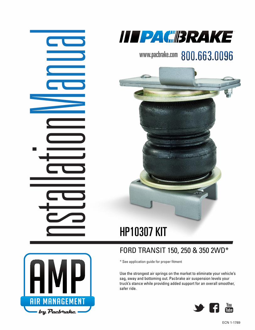
FORD TRANSIT 150, 250 & 350 2WD** See application guide for proper fitment
ECN 1-1789
HP10307 KIT
Use the strongest air springs on the market to eliminate your vehicle’s sag, sway and bottoming out. Pacbrake air suspension levels your truck’s stance while providing added support for an overall smoother, safer ride.

Pacbrake is a registered trademark of Pacbrake Co.
1
HP10307 AMP AIR SUSPENSION KIT L6444
ECN 1-1789
KIT CONTENT
REQUIRED TOOLS • Hoist or fl oor jacks• Safety stands• Safety Glasses• Torque wrench• Standard open-end combo wrenches• Ratchet• Metric and standard sockets• 7/32" Allen wrench (socket if available)• 5/16" drill bit (very sharp)• Drill• Hose cutter. Razor blade or sharp knife• Air compressor or compressed air source• Spray bottle with dish soap/water solution
Make sure all the items shown in the photo are provided in your kit before starting the installation.
A
B
G
NR
O
H
T
M
F
Q
I
PK
S
J
E
L
C
D
KIT CONTENTSA Axle Strap 2 HP1383B Frame Bracket 2 HP1500C Top Bracket 2 HP1501D Bottom Bracket 2 HP1502E Air Spring 2 HP10000DF Roll Plate 4 HP10054G Air Fitting 90̊ Swivel 2 HP1100H Tywrap 8 HP11618I Heat Shield 1 HP0012J Gear Clamp 2 HP1500K ⅜" – 24 X ⅞" Flat Head Socket Cap Screw 4 HP1008L ⅜" – 24 X ⅞" Hex Cap Screw 4 HP1002M Washer ⅜" Flat Plain Steel 12 C18006N ⅜" – 16 X 7" Carriage Bolt 4 HP1409O ⅜" – 16 X 1.25" Carriage Bolt 4 HP1149P M14 – 1.5 X 35 Button Head Screw 2 HP1414Q ⅜" – 16 Nyloc Nut 8 HP1000R Cable Clamp 2 HP1435S Air Line Assembly 1 HP1344T Gear Clamp 2 HP1001

Pacbrake is a registered trademark of Pacbrake Co.
2
HP10307 AMP AIR SUSPENSION KIT L6444
ECN 1-1789
KIT CONTENTS
A
B
C
D
EF
G
K
L
M
M
N
O
P
Q
Q
R
Pacbrake is a registered trademark of Pacbrake Co.
3
HP10307 AMP AIR SUSPENSION KIT L6444
ECN 1-1789
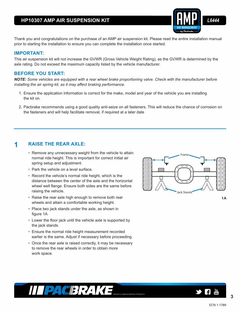
Jack Stands
Frame
1A
1 RAISE THE REAR AXLE:
• Remove any unnecessary weight from the vehicle to attain normal ride height. This is important for correct initial air spring setup and adjustment.
• Park the vehicle on a level surface.• Record the vehicle’s normal ride height, which is the
distance between the center of the axle and the horizontal wheel well fl ange. Ensure both sides are the same before raising the vehicle.
• Raise the rear axle high enough to remove both rear wheels and attain a comfortable working height.
• Place two jack stands under the axle, as shown in fi gure 1A
• Lower the fl oor jack until the vehicle axle is supported by the jack stands.
• Ensure the normal ride height measurement recorded earlier is the same. Adjust if necessary before proceeding.
• Once the rear axle is raised correctly, it may be necessary to remove the rear wheels in order to obtain morework space.
Thank you and congratulations on the purchase of an AMP air suspension kit. Please read the entire installation manual prior to starting the installation to ensure you can complete the installation once started.
IMPORTANT:This air suspension kit will not increase the GVWR (Gross Vehicle Weight Rating), as the GVWR is determined by the axle rating. Do not exceed the maximum capacity listed by the vehicle manufacturer.
BEFORE YOU START:NOTE: Some vehicles are equipped with a rear wheel brake proportioning valve. Check with the manufacturer before installing the air spring kit, as it may affect braking performance.
1. Ensure the application information is correct for the make, model and year of the vehicle you are installing the kit on.
2. Pacbrake recommends using a good quality anti-seize on all fasteners. This will reduce the chance of corrosion on the fasteners and will help facilitate removal, if required at a later date
Pacbrake is a registered trademark of Pacbrake Co.
4
HP10307 AMP AIR SUSPENSION KIT L6444
ECN 1-1789
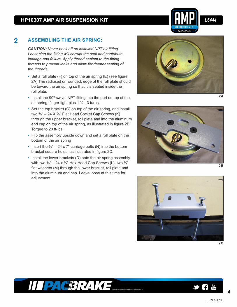
2 ASSEMBLING THE AIR SPRING:
CAUTION: Never back off an installed NPT air fi tting. Loosening the fi tting will corrupt the seal and contribute leakage and failure. Apply thread sealant to the fi tting threads to prevent leaks and allow for deeper seating of the threads.
• Set a roll plate (F) on top of the air spring (E) (see fi gure 2A) The radiused or rounded, edge of the roll plate should be toward the air spring so that it is seated inside the roll plate.
• Install the 90º swivel NPT fi tting into the port on top of the air spring, fi nger tight plus 1 ½ - 3 turns.
• Set the top bracket (C) on top of the air spring, and install two ⅜" – 24 X ⅞" Flat Head Socket Cap Screws (K) through the upper bracket, roll plate and into the aluminum end cap on top of the air spring, as illustrated in fi gure 2B. Torque to 20 ft-lbs.
• Flip the assembly upside down and set a roll plate on the bottom of the air spring
• Insert the ⅜" – 24 x 7" carriage bolts (N) into the bottom bracket square holes, as illustrated in fi gure 2C.
• Install the lower brackets (D) onto the air spring assembly with two ⅜" – 24 x ⅞" Hex Head Cap Screws (L), two ⅜" fl at washers (M) through the lower bracket, roll plate and into the aluminum end cap. Leave loose at this time for adjustment.
2A
2B
2C
Pacbrake is a registered trademark of Pacbrake Co.
5
HP10307 AMP AIR SUSPENSION KIT L6444
ECN 1-1789
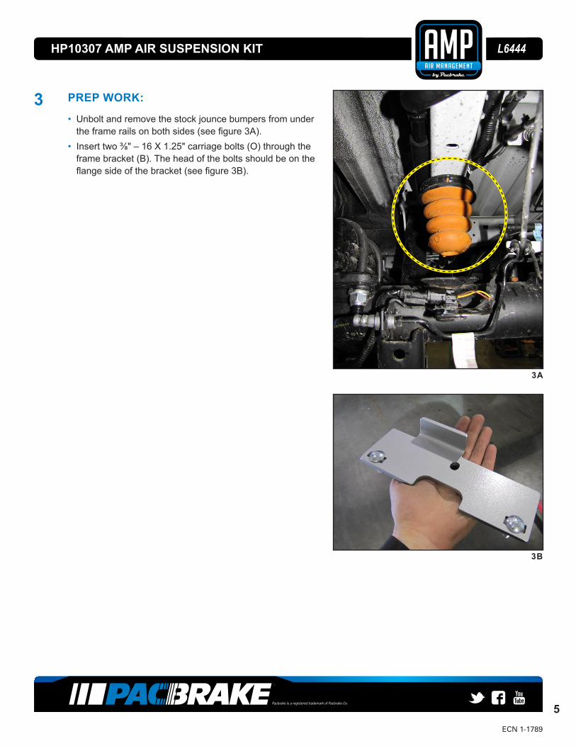
3 PREP WORK:
• Unbolt and remove the stock jounce bumpers from under the frame rails on both sides (see fi gure 3A).
• Insert two ⅜" – 16 X 1.25" carriage bolts (O) through the frame bracket (B). The head of the bolts should be on the fl ange side of the bracket (see fi gure 3B).
3B
3A
Pacbrake is a registered trademark of Pacbrake Co.
6
HP10307 AMP AIR SUSPENSION KIT L6444
ECN 1-1789
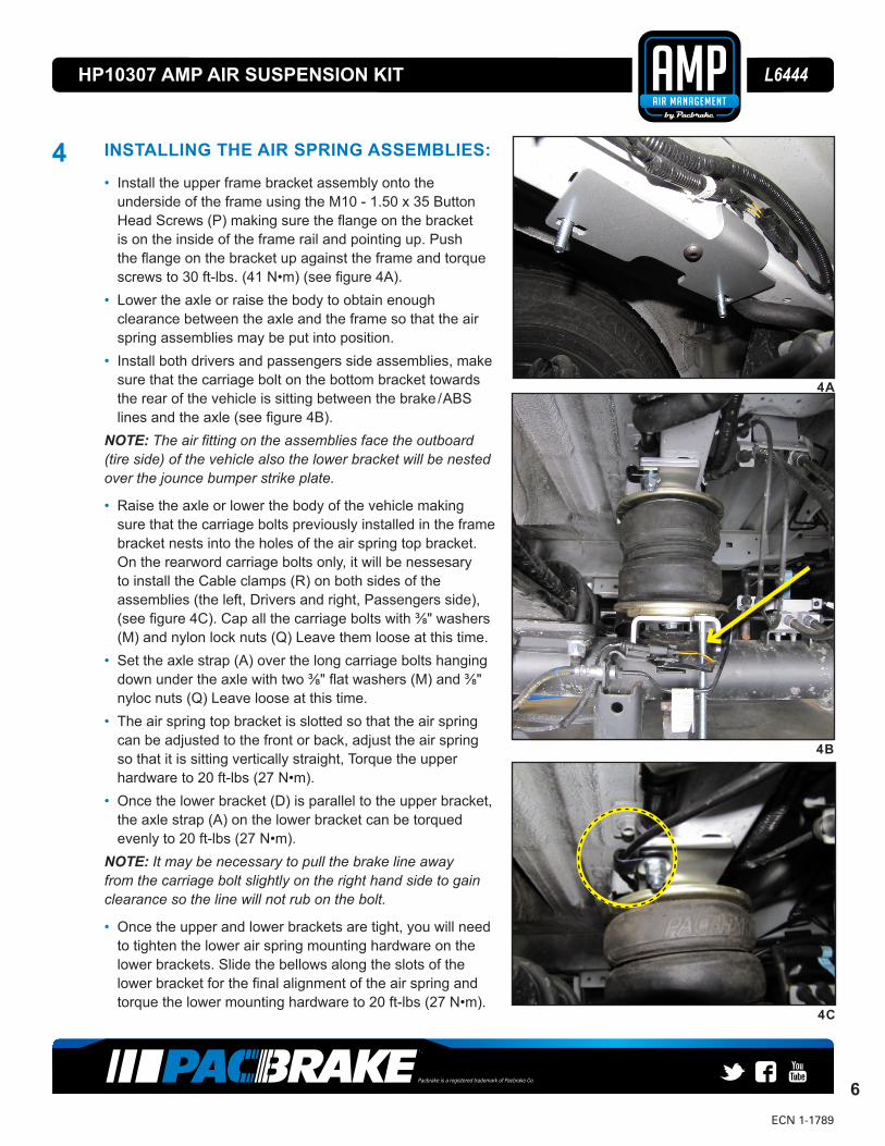
4 INSTALLING THE AIR SPRING ASSEMBLIES:
• Install the upper frame bracket assembly onto the underside of the frame using the M10 - 1.50 x 35 Button Head Screws (P) making sure the fl ange on the bracket is on the inside of the frame rail and pointing up. Push the fl ange on the bracket up against the frame and torque screws to 30 ft-lbs. (41 N•m) (see fi gure 4A).
• Lower the axle or raise the body to obtain enough clearance between the axle and the frame so that the air spring assemblies may be put into position.
• Install both drivers and passengers side assemblies, make sure that the carriage bolt on the bottom bracket towards the rear of the vehicle is sitting between the brake / ABS lines and the axle (see fi gure 4B).
NOTE: The air fi tting on the assemblies face the outboard (tire side) of the vehicle also the lower bracket will be nested over the jounce bumper strike plate.
• Raise the axle or lower the body of the vehicle making sure that the carriage bolts previously installed in the frame bracket nests into the holes of the air spring top bracket. On the rearword carriage bolts only, it will be nessesary to install the Cable clamps (R) on both sides of the assemblies (the left, Drivers and right, Passengers side), (see fi gure 4C). Cap all the carriage bolts with ⅜" washers (M) and nylon lock nuts (Q) Leave them loose at this time.
• Set the axle strap (A) over the long carriage bolts hanging down under the axle with two ⅜" fl at washers (M) and ⅜" nyloc nuts (Q) Leave loose at this time.
• The air spring top bracket is slotted so that the air spring can be adjusted to the front or back, adjust the air spring so that it is sitting vertically straight, Torque the upper hardware to 20 ft-lbs (27 N•m).
• Once the lower bracket (D) is parallel to the upper bracket, the axle strap (A) on the lower bracket can be torqued evenly to 20 ft-lbs (27 N•m).
NOTE: It may be necessary to pull the brake line away from the carriage bolt slightly on the right hand side to gain clearance so the line will not rub on the bolt.
• Once the upper and lower brackets are tight, you will need to tighten the lower air spring mounting hardware on the lower brackets. Slide the bellows along the slots of the lower bracket for the fi nal alignment of the air spring and torque the lower mounting hardware to 20 ft-lbs (27 N•m).
4C
4B
4A

Pacbrake is a registered trademark of Pacbrake Co.
7
HP10307 AMP AIR SUSPENSION KIT L6444
ECN 1-1789
Air Line
Schrader Valve
Hex Nut
Flat Washer
Vehicle Body
Valve Cap
1 2 3 4 5 6 7 8
7654321 8
A
B
C
D
E
A
B
D
E
C
UNAUTHORIZED DISCLOSURE, USE OR MANUFACTURE IN WHOLE OR IN PART IS PROHIBITED.DRAWING DESIGN AND OTHER DISCLOSURES PROPERTY OF PACBRAKE CO. SURREY, B.C., CANADA
CUSTOMER PART #:
APP:CHK:DESCRIPTION:D.M.Y.ECN:
MATERIAL:
1:2SIZE:
INTERPRET ALL DIMENSIONSAND TOLERANCES
PER ASME Y14.5-2009
THIRD ANGLE PROJECTION
A
SCALE: PART NAME:
CAD NO.:
1AirLineAssembly OF
1SHEET
0.0 kgWEIGHT: APP:ENG:D.M.Y.
UNLESS OTHERWISE SPECIFIED:
DIMENSIONS: mm
TOLERANCES: ;
SURFACE FINISH:
CHK:
ENG:
AirLineAssemblyDWG NO.:
File: S:\masterfile\Documentation\PAC-091A-DOC_Rev2.SLDDRT Date: 23/Apr/2014
6A
5 FINISHING STEPS:
• On the driver side behind the axle, the ABS line may need to be adjusted so that it will not rub on the lower bracket.
• To do this pull the line out of the holder and rotate it 180º then push it back into the holder. This will change the position of the line so that it will not come in contact with the lower bracket.
6 INSTALLING THE AIRLINE:
• Choose a convenient location for mounting the infl ation valves. Popular locations for the INFLATION VALVE ARE:A The wheel well fl anges.B The license plate recess in bumper.C Under the gas cap access door.D Through the license plate.
NOTE: Whatever the chosen location, make sure there is enough clearance around the infl ation valves for an air chuck.
• Drill two 5⁄16" holes to install the infl ation valves.• Cut the airline assembly in two equal lengths.
Pacbrake is a registered trademark of Pacbrake Co.
8
HP10307 AMP AIR SUSPENSION KIT L6444
ECN 1-1789
6 INSTALLING THE AIRLINE (CONTINUED):
CAUTION: WHEN CUTTING OR TRIMMING THE AIR LINE, USE A HOSE CUTTER, A RAZOR BLADE, OR A SHARP KNIFE. A CLEAN, SQUARE CUT WILL ENSURE AGAINST LEAKS. DO NOT USE WIRE CUTTERS OR SCISSORS TO CUT THE AIR LINE. THESE TOOLS MAY FLATTEN OR CRIMP THE AIR LINE CAUSING IT TO LEAK AROUND THE O-RING SEAL INSIDE THE ELBOW FITTING.
• Place a 5⁄16" nut on the air valve. Leave enough of the infl ation valve In front of the nut to extend through the hole, install a fl at washer and 5⁄16" nut and cap. There should be enough valve exposed after installation— Approximately ½"— to easily apply a pressure gauge or an air chuck.
• Push the infl ation valve through the hole, install a fl at washer, and another 5⁄16" nut to secure it in place. Tighten the nuts to secure the assembly.
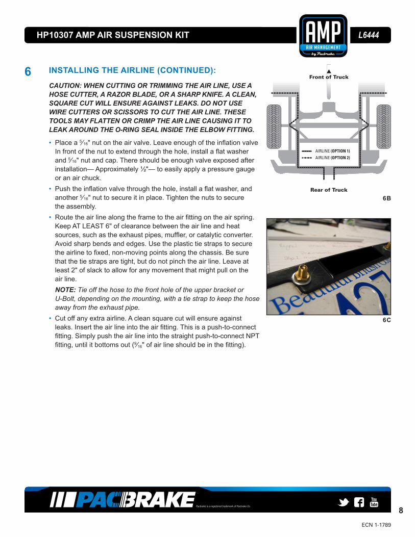
• Route the air line along the frame to the air fi tting on the air spring. Keep AT LEAST 6" of clearance between the air line and heat sources, such as the exhaust pipes, muffl er, or catalytic converter. Avoid sharp bends and edges. Use the plastic tie straps to secure the airline to fi xed, non-moving points along the chassis. Be sure that the tie straps are tight, but do not pinch the air line. Leave at least 2" of slack to allow for any movement that might pull on the air line.NOTE: Tie off the hose to the front hole of the upper bracket or U-Bolt, depending on the mounting, with a tie strap to keep the hose away from the exhaust pipe.
• Cut off any extra airline. A clean square cut will ensure against leaks. Insert the air line into the air fi tting. This is a push-to-connect fi tting. Simply push the air line into the straight push-to-connect NPT fi tting, until it bottoms out (9⁄16" of air line should be in the fi tting).
6B
AIRLINE (OPTION 1)
AIRLINE (OPTION 2)
Front of Truck
Rear of Truck
6C
Pacbrake is a registered trademark of Pacbrake Co.
9
HP10307 AMP AIR SUSPENSION KIT L6444
ECN 1-1789
9A
7A
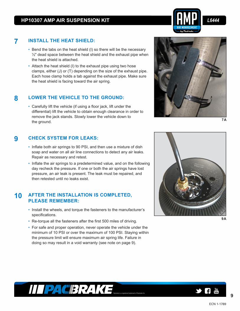
7 INSTALL THE HEAT SHIELD:
• Bend the tabs on the heat shield (I) so there will be the necessary ½" dead space between the heat shield and the exhaust pipe when the heat shield is attached.
• Attach the heat shield (I) to the exhaust pipe using two hose clamps, either (J) or (T) depending on the size of the exhaust pipe. Each hose clamp holds a tab against the exhaust pipe. Make sure the heat shield is facing toward the air spring.
8 LOWER THE VEHICLE TO THE GROUND:
• Carefully lift the vehicle (if using a fl oor jack, lift under the differential) lift the vehicle to obtain enough clearance in order to remove the jack stands. Slowly lower the vehicle down to the ground.
9 CHECK SYSTEM FOR LEAKS:
• Infl ate both air springs to 90 PSI, and then use a mixture of dish soap and water on all air line connections to detect any air leaks. Repair as necessary and retest.
• Infl ate the air springs to a predetermined value, and on the following day recheck the pressure. If one or both the air springs have lost pressure, an air leak is present. The leak must be repaired, and then retested until no leaks exist.
10 AFTER THE INSTALLATION IS COMPLETED, PLEASE REMEMBER:
• Install the wheels, and torque the fasteners to the manufacturer’s specifi cations.
• Re-torque all the fasteners after the fi rst 500 miles of driving.• For safe and proper operation, never operate the vehicle under the
minimum of 10 PSI or over the maximum of 100 PSI. Staying within the pressure limit will ensure maximum air spring life. Failure in doing so may result in a void warranty (see note on page 9).
Pacbrake is a registered trademark of Pacbrake Co.
10
HP10307 AMP AIR SUSPENSION KIT L6444
ECN 1-1789Rev3 31.01.18
OPTIONAL ACCESSORIESPacbrake offers an optional dual needle air gauge to monitor the pressure in each spring from the vehicles cab. Pacbrake offers a full line of air compressors, air tanks and solenoids to control your air spring system.
OPERATING YOUR VEHICLE WITH PACBRAKE AIR SUSPENSIONAir springs have minimum and maximum pressure requirements. Never operate your vehicle with less than 10 PSI in the air spring and never inflate the air springs over 100 PSI. Staying within the pressure limit will ensure maximum air spring life. Failure in doing so may void the warranty. Check the air pressure in the air springs daily for the first couple of days to ensure a leak does not develop. The air springs are designed to maintain the vehicles stock ride height with a load. Do not use the air springs as a means to lift the vehicle with no load. A rough ride will result.
SERVICING YOUR VEHICLE WITH PACBRAKE AIR SUSPENSIONWhen lifting the vehicle with a floor jack or hoist on the frame, never allow the air spring to limit the travel of the axle. Try to always jack the vehicle on the axle. Suspending the axle with the air spring limiting the axle travel will damage the air spring and void the air spring warranty.
WARRANTYTo be eligible for warranty, owner must submit their warranty card or register online within 30 days of purchase date.
NOTE: The owners warranty will be void if air springs run with less than the minimum of 10 PSI.
L6444