Embed Size (px)
Citation preview
HP10220 KIT2005 - 2011 Dodge Dakota* (2WD/4WD)* 2005 – All Dodge Dakotas 2006 - All Dodge Dakotas except Night Runner and R/T sub models 2007 - All Dodge Dakotas except SXT and TRX4 sub models 2008 - All Dodge Dakotas except Big Horn sub models 2009 – All Dodge Dakotas 2010 – All Dodge Dakotas 2011 – All Dodge Dakotas except Lone Star sub models
Use the strongest air springs on the market to eliminate your vehicle’s sag, sway and bottoming out. Pacbrake air suspension levels your truck’s stance while providing added support for an overall smoother, safer ride.

Pacbrake is a registered trademark of Pacbrake Co.
1
HP10220 AMP AIR SUSPENSION KIT L6370
KIT CONTENT
REQUIRED TOOLS • 7⁄16", 9⁄16" Open End or Box Wrenches• Ratchet with 3⁄8", 9⁄16", and ½"
deep sockets• 3⁄8", 5⁄16" and 9⁄16" drill bits (very sharp)• 3⁄8" Nut Driver• Crescent Wrench• Torque Wrench• Heavy Duty Drill• Hoist or Floor Jacks• Safety Stands• Safety Glasses• Air Compressor or Compressed
Air Source• Spray Bottle with Dish Soap &
Water Solution
Make sure all the items shown in the photo are provided in your kitbefore starting the installation.
KIT CONTENTS
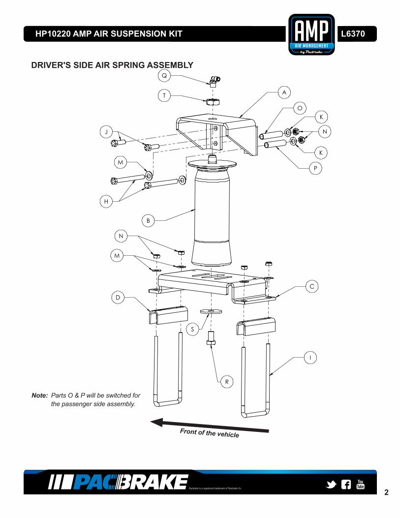
A Upper Bracket (2) HP0046B Air Spring (2) HP10001C Lower Bracket (2) HP0104D Spacer Clamp Bar (4) HP0113E Install Tool (1) HP0048F Heat Shield (1) HP0012G Gear Clamp (2) HP1001H 3⁄8"-16 x 4" Hex Cap Bolt (4) HP1437I 3⁄8"-16 U-Bolt (4) HP1018J 3⁄8" x 1.25" Self-Threading Screw (4) HP1078K 3⁄8" Flat Washer (4) C18006L Tie Strap (6) C11618M 3⁄8" Flat Washer SAE (12) C653N 3⁄8"-16 Nyloc Nut (12) HP1000O 2.70" Spacer (2) HP1439P 2.55" Spacer (2) HP1438Q 90° Swivel Air Fitting (2) HP1019R 1⁄2 "-13 x 7⁄8" Hex Head Cap Screw (2) HP1077S 3⁄4" Washer, 2" OD (2) HP1010T 3⁄4" Jam Nut (2) HP1076U Tube Cutter (1) C3941V Air Line Assembly (1) HP1344
A
N
Q
R T
S
D
K
B
H
JI
L O P
V
G
C
M
E
F
U
Pacbrake is a registered trademark of Pacbrake Co.
2
HP10220 AMP AIR SUSPENSION KIT L6370
Q
T A
O
K
P
C
I
R
S
D
M
B
N
H
J N
K
M
1 2 3 4 5 6 7 8
A
B
C
D
E
UNAUTHORIZED DISCLOSURE, USE OR MANUFACTURE IN WHOLE OR IN PART IS PROHIBITED.DRAWING DESIGN AND OTHER DISCLOSURES PROPERTY OF PACBRAKE CO. SURREY, B.C., CANADA
CUSTOMER PART #:
APP:CHK:DESCRIPTION:D.M.Y.ECN:
MATERIAL:
1:10SIZE:
INTERPRET ALL DIMENSIONSAND TOLERANCES
PER ASME Y14.5-2009
THIRD ANGLE PROJECTION
B
SCALE: PART NAME:
CAD NO.:
1AssemblyOF
1SHEET
12.1 kgWEIGHT: APP:ENG:D.M.Y.
UNLESS OTHERWISE SPECIFIED:
DIMENSIONS: mm
TOLERANCES: ;
SURFACE FINISH:
CHK:
F
G
10 12119 13
72 111 4 8 105 9 1263 13
G
B
E
D
A
F
C
ENG:
DWG NO.:
File: S:\masterfile\Documentation\PAC-091B-DOC_Rev2.SLDDRT Date: 23/Apr/2014
Assem2
DRIVER'S SIDE AIR SPRING ASSEMBLY
Note: Parts O & P will be switched for the passenger side assembly.
Front of the vehicle

Pacbrake is a registered trademark of Pacbrake Co.
3
HP10220 AMP AIR SUSPENSION KIT L6370
Jack Stands
Frame
1A
1B
Thank you and congratulations on the purchase of an AMP air suspension kit. Please read the entire installation manual prior to starting the installation to ensure you can complete the installation once started. Should you have any questions during the installation, please call Pacbrake at 800.663.0096.
IMPORTANT:This air suspension kit will not increase the GVWR (Gross Vehicle Weight Rating), as the GVWR is determined by the axle rating. Do not exceed the maximum capacity listed by the vehicle manufacturer.
NOTE: Some vehicles are equipped with a real brake proportioning valve. Check this with the vehicle manufacturer before installing the air spring kit, as it may affect braking performance.
BEFORE YOU START1. Ensure the application information is correct for the make, model and year of the vehicle you are installing the kit on.
2. Check the clearance between the outside of the frame and the inside of the tire. A minimum of 6" is required for air spring clearance.
3. Pacbrake recommends using a good quality anti-seize on all fasteners. This will reduce the chance of corrosion on the fasteners and will help facilitate removal, if required at a later date.
1 RAISE THE REAR AXLE
• Removeanyunnecessaryweightfromthevehicletoattainnormalride height. This is important for correct initial air spring setup and adjustment.
• Parkthevehicleonalevelsurface.
• Recordthevehicle’snormalrideheight,whichisthedistancebetweenthecenteroftheaxleandthetopofthewheelwellflange.Ensureboth sides are the same before raising the vehicle.
• Raisetherearaxlehighenoughtoremovebothrearwheelsandattain a comfortable working height.
• Placetwojackstandsundertheaxle,asshowninthephoto.
• Lowerthefloorjackuntilthevehicleaxleissupportedbythe jack stands.
• Ensurethenormalrideheightmeasurementrecordedearlieris the same.
• Adjustifnecessarybeforeproceeding.
• Oncetherearaxleisraisedcorrectly,removetherearwheels.
6" 6"

Pacbrake is a registered trademark of Pacbrake Co.
4
HP10220 AMP AIR SUSPENSION KIT L6370
2A
3B
3A
2 ASSEMBLE THE INSTALLATION TOOL
• Theinstallationtoolwillaligntheupperandlowerbrackets as well as position the upper bracket for drilling the bolt holes. The threaded section of the installation tool is the range in which the air spring height may be set. It is advisable to set it to the maximum height possible.
• Usingthelarge½"fenderwasher(S)andthe½"x 7⁄8" bolt (R) provided, attach the installation tool (E) to the lowerbracket(C)andfingertighten.
• Installoneofthe3⁄4" - 16 jam nuts (T) on to the installation tool (E). Attach the upper bracket (A) to the installation tool (E) and fasten it together with a 3⁄4" - 16 jam nut (T).
• Figure2Ashowshowthefinishedassemblyshould look. It will be used in the next step.
3 ATTACH THE LOWER BRACKET
• Begintheinstallationprocessonthedriver'sside.
• Settheassemblyontotheleafspring,overtheaxle(seefigure3A).
• Usetheoptionalspacers(D)toraisethelowerbracket(C)ifitinterferes with the stock U-bolts holding the leaf spring in place.
• Positionthelowerbracket(C)sothattherearlegoftheupperbracket(A)isflushagainsttheweldwherethetwoframesectionscometogether(Seefigure3B).
NOTE: The front leg of the upper bracket will mount on the raised portion of the frame and the rear leg of the upper bracket will mount on the recessed, rear portion of the frame (See Figure 3B).
3/4" Jam Nut X 2 (T)
Upper Bracket (A)
Installation Tool (E)
Lower Bracket (C)
1/2" Washer (S)1/2" Hex Cap Screw (R)
1 2 3 4 5 6 7 8
A
B
C
D
E
UNAUTHORIZED DISCLOSURE, USE OR MANUFACTURE IN WHOLE OR IN PART IS PROHIBITED.DRAWING DESIGN AND OTHER DISCLOSURES PROPERTY OF PACBRAKE CO. SURREY, B.C., CANADA
CUSTOMER PART #:
APP:CHK:DESCRIPTION:D.M.Y.ECN:
MATERIAL:
1:5SIZE:
INTERPRET ALL DIMENSIONSAND TOLERANCES
PER ASME Y14.5-2009
THIRD ANGLE PROJECTION
B
SCALE: PART NAME:
CAD NO.:
1InstallAssemblyOF
1SHEET
9.7 kgWEIGHT: APP:ENG:D.M.Y.
UNLESS OTHERWISE SPECIFIED:
DIMENSIONS: mm
TOLERANCES: ;
SURFACE FINISH:
CHK:
F
G
10 12119 13
72 111 4 8 105 9 1263 13
G
B
E
D
A
F
C
ENG:
DWG NO.:
File: S:\masterfile\Documentation\PAC-091B-DOC_Rev2.SLDDRT Date: 23/Apr/2014
InstallAssembly
MIN. 1.50" OF CLEARANCE
Rear Leg of the Upper Bracket
Frame Weld
Vehicle Frame
Front Lower Bolt Rear Lower Bolt
1 2 3 4 5 6 7 8
A
B
C
D
E
UNAUTHORIZED DISCLOSURE, USE OR MANUFACTURE IN WHOLE OR IN PART IS PROHIBITED.DRAWING DESIGN AND OTHER DISCLOSURES PROPERTY OF PACBRAKE CO. SURREY, B.C., CANADA
CUSTOMER PART #:
APP:CHK:DESCRIPTION:D.M.Y.ECN:
MATERIAL:
1:5SIZE:
INTERPRET ALL DIMENSIONSAND TOLERANCES
PER ASME Y14.5-2009
THIRD ANGLE PROJECTION
B
SCALE: PART NAME:
CAD NO.:
1FrameAssemblyOF
1SHEET
6.2 kgWEIGHT: APP:ENG:D.M.Y.
UNLESS OTHERWISE SPECIFIED:
DIMENSIONS: mm
TOLERANCES: ;
SURFACE FINISH:
CHK:
F
G
10 12119 13
72 111 4 8 105 9 1263 13
G
B
E
D
A
F
C
ENG:
DWG NO.:
File: S:\masterfile\Documentation\PAC-091B-DOC_Rev2.SLDDRT Date: 23/Apr/2014
FrameAssembly
Note: Figure 3B shows the assembly from the driver's side. The passenger's side will be the opposite of figure 3B

Pacbrake is a registered trademark of Pacbrake Co.
5
HP10220 AMP AIR SUSPENSION KIT L6370
4A
• Securethelowerbracket(C)totheleafspringwithtwoU-bolts(I),fourflatwashers(M)andfournylocnuts(N). (Seedriver'ssideairspringassembly,page2).
• Torquethenuts(N)to20ft-lbs(27N•m).
• Theairspringwillexpandto5.10"indiameteratmaximuminflationpressure. Check horizontally along the shaft of the installation tool (E) forsufficientclearanceof2.50"allaroundthetool.
4 POSITION THE UPPER BRACKET
• Usingtheslotinthelowerbracket(C),positiontheupperbracket(A)sothattheupperbracket(A)isflushagainsttheframerail.
• Usethetwojamnuts(T)onthethreadedportiontoadjusttheupperbrackets (A) height. It is recommended to set it to the maximum height possible.
NOTE: There must be at least 1.50" of clearance above the upper bracket to allow for installation of the air fitting.
• Withtherearlegoftheupperbracket(A)flushagainsttheweld,raiseor lower the bracket so the self-tapping screw will be below the radius of the frame. (See Figure 5C)
MIN. 1.50" OF CLEARANCE
Rear Leg of the Upper Bracket
Frame Weld
Vehicle Frame
Front Lower Bolt Rear Lower Bolt
1 2 3 4 5 6 7 8
A
B
C
D
E
UNAUTHORIZED DISCLOSURE, USE OR MANUFACTURE IN WHOLE OR IN PART IS PROHIBITED.DRAWING DESIGN AND OTHER DISCLOSURES PROPERTY OF PACBRAKE CO. SURREY, B.C., CANADA
CUSTOMER PART #:
APP:CHK:DESCRIPTION:D.M.Y.ECN:
MATERIAL:
1:5SIZE:
INTERPRET ALL DIMENSIONSAND TOLERANCES
PER ASME Y14.5-2009
THIRD ANGLE PROJECTION
B
SCALE: PART NAME:
CAD NO.:
1FrameAssemblyOF
1SHEET
6.2 kgWEIGHT: APP:ENG:D.M.Y.
UNLESS OTHERWISE SPECIFIED:
DIMENSIONS: mm
TOLERANCES: ;
SURFACE FINISH:
CHK:
F
G
10 12119 13
72 111 4 8 105 9 1263 13
G
B
E
D
A
F
C
ENG:
DWG NO.:
File: S:\masterfile\Documentation\PAC-091B-DOC_Rev2.SLDDRT Date: 23/Apr/2014
FrameAssembly
Note: Figure 4A shows the assembly from the driver's side.

Pacbrake is a registered trademark of Pacbrake Co.
6
HP10220 AMP AIR SUSPENSION KIT L6370
5D
J
H M
A
K
NO/P
Radius of the frame
Outside of the frame
Inside of the frame
1 2 3 4 5 6 7 8
A
B
C
D
E
UNAUTHORIZED DISCLOSURE, USE OR MANUFACTURE IN WHOLE OR IN PART IS PROHIBITED.DRAWING DESIGN AND OTHER DISCLOSURES PROPERTY OF PACBRAKE CO. SURREY, B.C., CANADA
CUSTOMER PART #:
APP:CHK:DESCRIPTION:D.M.Y.ECN:
MATERIAL:
1:5SIZE:
INTERPRET ALL DIMENSIONSAND TOLERANCES
PER ASME Y14.5-2009
THIRD ANGLE PROJECTION
B
SCALE: PART NAME:
CAD NO.:
1Assem2-withframeOF
1SHEET
13.2 kgWEIGHT: APP:ENG:D.M.Y.
UNLESS OTHERWISE SPECIFIED:
DIMENSIONS: mm
TOLERANCES: ;
SURFACE FINISH:
CHK:
F
G
10 12119 13
72 111 4 8 105 9 1263 13
G
B
E
D
A
F
C
ENG:
DWG NO.:
File: S:\masterfile\Documentation\PAC-091B-DOC_Rev2.SLDDRT Date: 23/Apr/2014
Assem2-withframe
5 ATTACH THE UPPER BRACKET
CAUTION: Before drilling, check the back side of the frame for clearance issues such as, brake lines, gas lines, electrical lines, etc. Any obstacles will need to be temporarily relocated to clear the area.
• Centerpunchbothlowerholesintheupperbracket(A)anddrilltwo3⁄8" holes all the way through both sides of the frame. (Seefigure5A-5D)
• Centerpunchbothupperholesintheupperbracket(A)anddrilltwo5⁄16" holes through the OUTSIDE WALL OF THE FRAME ONLY. (See Figure 5A - 5D)
• Detachtheinstallationtool(E)fromtheupper(A)andlowerbrackets(C). Save the tool and its corresponding hardware as it will be reused to mount the other air spring.
CAUTION: You may have to pull the electrical line holder out of the frame on the inside of the driver-side frame. Reattach using the provided tie straps (L).
• Drillthe3⁄8" holes on the inside of the frame to 9⁄16" in order to provide enough room for the frame spacers to be installed into the frame. (See Figure 5D)
• Attachtheupperbracket(A)totheframebyinsertingtwo3⁄8" x 4" bolts (H), with two washers (M) through the lower holes in the upper bracket (A) (See Figure 5D).
• Insertthespacersthroughthe9⁄16" hole drilled through the inside of the frame. The long spacer (O) goes through the front lower bolt. The shorter spacer (P) goes through the rear lower bolt. (Seefigure4Aand5D)
• Fastentheupperbracket(A)totheframebyinstallingtwowide3⁄8" washers (K) and two 3⁄8" nuts (N) onto the 3⁄8" x 4" bolts (H) (See Figure 5D)
• Inserttwoself-threadingbolts(J)intothetopholesandtightento 15ft-lbs(20N•m),be careful not to overtighten. Torque the two lowerboltsto44ft-lbs(60N•m).
5A
5B
5C

Pacbrake is a registered trademark of Pacbrake Co.
7
HP10220 AMP AIR SUSPENSION KIT L6370
NOTE: The spacers are to keep the frame from crushing. It is possible that some crushing may occur while tightening the bolts.
6 INSTALL THE AIR SPRING• Preparetheairspringbyensuringthatitiscollapsedwiththerubber
part of the bag folded over the bottom end cap. (See Figure 6A).
• Installthe90°airswivelfitting(Q)intothetopoftheairspring(B).Fingertightentheswivelfittingandturnanextra1.5turnswitha7⁄16" wrench to tighten.
• Guidethefittingthroughthecentermountingholeinthe upperbracket(A).(Seedriver'ssideairspringassembly,page2).
• Attachtheairspring(B)tothelowerbracket(C)usinga1⁄2"flatwasher (S) and a 1⁄2" bolt (R). Leave it loose to allow for adjustment. (Seedriver'ssideairspringassembly,page2).
• Installa3⁄4"jamnut(T)overtheairfittingandontotheupperthreadedpostoftheairspring.Tightento25ft-lbs(34N•m).
Note: This jam nut will be required for the passenger side installation. Install the jam nut over the threaded post of the air spring on the driver's side AFTER completing steps 1-6 on the passenger's side.
7 INSTALL THE AIR LINESNOTE: This kit contains push to connect fittings, using scissors or wire cutters to cut the nylon airline will distort the line and cause the connection to leak. USE THE PROVIDED TUBE CUTTER (U) TO CUT THE HOSE TO LENGTH. Moisten the end of the airline prior to inserting it into the fitting and push it in until it stops.
• Providedintheairspringkitaretwofillvalvesattachedtoanylonhose(V).Cutthehoseinto2equallengthswith the tube cutter (U).
• Themostcommonplacetoinstallitistoreplacethelicenseplatefastenerswiththefillvalves(Figure7A).
• Alternatively,two5⁄16"holescanbedrilledinaconvenientlocationandthefittingscanbeinstalledthere.
• ChoosealocationandinstallthefillvalveaccordingtothediagraminFigure7B.
7A
6A
7B
Air Line
Schrader Valve
Hex Nut
Flat Washer
Vehicle Body
Valve Cap
1 2 3 4 5 6 7 8
7654321 8
A
B
C
D
E
A
B
D
E
C
UNAUTHORIZED DISCLOSURE, USE OR MANUFACTURE IN WHOLE OR IN PART IS PROHIBITED.DRAWING DESIGN AND OTHER DISCLOSURES PROPERTY OF PACBRAKE CO. SURREY, B.C., CANADA
CUSTOMER PART #:
APP:CHK:DESCRIPTION:D.M.Y.ECN:
MATERIAL:
1:2SIZE:
INTERPRET ALL DIMENSIONSAND TOLERANCES
PER ASME Y14.5-2009
THIRD ANGLE PROJECTION
A
SCALE: PART NAME:
CAD NO.:
1AirLineAssembly OF
1SHEET
0.0 kgWEIGHT: APP:ENG:D.M.Y.
UNLESS OTHERWISE SPECIFIED:
DIMENSIONS: mm
TOLERANCES: ;
SURFACE FINISH:
CHK:
ENG:
AirLineAssemblyDWG NO.:
File: S:\masterfile\Documentation\PAC-091A-DOC_Rev2.SLDDRT Date: 23/Apr/2014
Pacbrake is a registered trademark of Pacbrake Co.
8
HP10220 AMP AIR SUSPENSION KIT L6370
9A
8A
• Routeoneendofthenylonhosefromtheinflationvalvetoanairspringfitting(Q).Cutthehoseandconnectittotheairspringfitting(Q).Repeatwiththeotherfillvalve.
• Secureairlineswiththetie-straps(L)provided.Ensurethattheairlinesare away from moving items and heat sources.
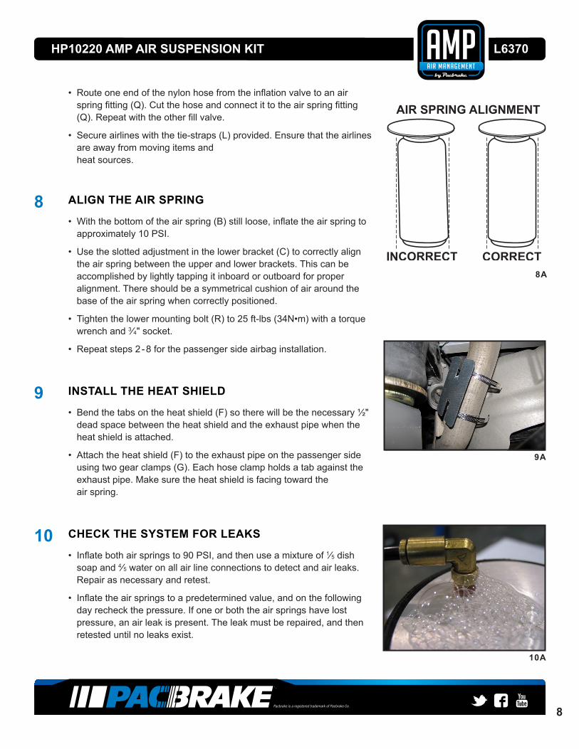
8 ALIGN THE AIR SPRING
• Withthebottomoftheairspring(B)stillloose,inflatetheairspringtoapproximately 10 PSI.
• Usetheslottedadjustmentinthelowerbracket(C)tocorrectlyalignthe air spring between the upper and lower brackets. This can be accomplished by lightly tapping it inboard or outboard for proper alignment. There should be a symmetrical cushion of air around the base of the air spring when correctly positioned.
• Tightenthelowermountingbolt(R)to25ft-lbs(34N•m)withatorquewrench and 3⁄4" socket.
• Repeatsteps2-8forthepassengersideairbaginstallation.
9 INSTALL THE HEAT SHIELD
• Bendthetabsontheheatshield(F)sotherewillbethenecessary½"dead space between the heat shield and the exhaust pipe when the heat shield is attached.
• Attachtheheatshield(F)totheexhaustpipeonthepassengersideusing two gear clamps (G). Each hose clamp holds a tab against the exhaust pipe. Make sure the heat shield is facing toward the air spring.
10 CHECK THE SYSTEM FOR LEAKS
• Inflatebothairspringsto90PSI,andthenuseamixtureof1⁄5 dish soap and 4⁄5 water on all air line connections to detect and air leaks. Repair as necessary and retest.
• Inflatetheairspringstoapredeterminedvalue,andonthefollowingday recheck the pressure. If one or both the air springs have lost pressure, an air leak is present. The leak must be repaired, and then retested until no leaks exist.
10A

Pacbrake is a registered trademark of Pacbrake Co.
9
HP10220 AMP AIR SUSPENSION KIT L6370
11 AFTER THE INSTALLATION IS COMPLETE PLEASE REMEMBER
• Installthewheels,andtorquethefastenerstothemanufacturesspecifications.
• Re-torqueallthefastenersafterthefirst500milesofdriving.
• Forsafeandproperoperation,neveroperatethevehicleundertheminimum of 10 PSI or over the maximum of 100 PSI. Staying within the pressure limit will ensure maximum air spring life. Failure in doing so may result in a void warranty. (See below)
OPTIONAL ACCESSORIES Pacbrakeoffersanoptionaldualneedleairgaugetomonitorthepressureineachairspringfromthevehicle’scab.Pacbrake also offers a full line of air compressors, air tanks and solenoids to control your air spring system.
OPERATING YOUR VEHICLE WITH PACBRAKE AIR SUSPENSION Air springs have minimum and maximum pressure requirements. Never operate your vehicle with less than 10 PSI in the airspringandneverinflatetheairspringsover100PSI,ortheairspringswillbedamaged.
Checktheairpressureintheairspringsdailyforthefirstcoupleofdaystoensurealeakdoesnotdevelop.Theairspringsaredesignedtomaintainthevehicle’sstockrideheightwithaload.Donotusetheairspringsasameanstoliftthe vehicle with no load, or a rough ride will result.
SERVICING YOUR VEHICLE WITH PACBRAKE AIR SUSPENSION Whenliftingthevehiclewithafloorjackorhoistontheframe,neverallowtheairspringtolimitthetraveloftheaxle:tryto always jack the vehicle on the axle. Suspending the axle with the air spring limiting the axle travel will damage the air spring and void the air spring warranty.
WARRANTY To be eligible for warranty, the owner must submit their warranty card or register online within 30 days of purchase date.
NOTE: The owner’s warranty will be void if the air springs run with less than the minimum of 10 PSI or greater than the maximum of 100 PSI. Stay within these pressures to ensure maximum air spring life.
L6373_10.03.2016