Embed Size (px)
Citation preview

EL-MF877-00 Page 1
Template Revision B
PSG instructions for this template are available at EL-MF877-01
Product End-of-Life Disassembly Instructions Product Category: Personal Computers
Marketing Name / Model [List multiple models if applicable.]
HP TouchSmart IQ500 series PC
Purpose: The document is intended for use by end-of-life recyclers or treatment facilities. It provides the basic instructions for the disassembly of HP products to remove components and materials requiring selective treatment, as defined by EU directive 2002/96/EC, Waste Electrical and Electronic Equipment (WEEE).
1.0 Items Requiring Selective Treatment
1.1 Items listed below are classified as requiring selective treatment. 1.2 Enter the quantity of items contained within the product which require selective treatment in the right column, as applicable.
Item Description Notes
Quantity of items included in product
Printed Circuit Boards (PCB) or Printed Circuit Assemblies (PCA)
With a surface greater than 10 sq cm
10
Batteries All types including standard alkaline and lithium coin or button style batteries
1
Mercury-containing components For example, mercury in lamps, display backlights, scanner lamps, switches, batteries
4
Liquid Crystal Displays (LCD) with a surface greater than 100 sq cm
Includes background illuminated displays with gas discharge lamps
1
Cathode Ray Tubes (CRT) 0
Capacitors / condensers (Containing PCB/PCT) 0
Electrolytic Capacitors / Condensers measuring greater than 2.5 cm in diameter or height
0
External electrical cables and cords 3
Gas Discharge Lamps 0
Plastics containing Brominated Flame Retardants weighing > 25 grams (not including PCBs or PCAs already listed as a separate item above)
0
Components and parts containing toner and ink, including liquids, semi-liquids (gel/paste) and toner
Include the cartridges, print heads, tubes, vent chambers, and service stations.
0
Components and waste containing asbestos 0

EL-MF877-00 Page 2
Template Revision B
PSG instructions for this template are available at EL-MF877-01
Components, parts and materials containing refractory ceramic fibers
0
Components, parts and materials containing radioactive substances
0
1.3 Markings for plastic parts greater than 25 grams
Plastic Part Name Plastic Part Description Weight (grams)
ISO 11469:2000 Plastic Part
Mark Optional:
Photo
JAN_MAIN_REAR_COVER JAN_MAIN_REAR_COVER 267g >ABS<
JAN_CHIN JAN_CHIN 118.25g >ABS<
JAN_SIDE_CAP_RT JAN_SIDE_CAP_RT 28.2g >PMMA<
JAN_SIDE_CAP_RT JAN_SIDE_CAP_RT 28.2g PC+ABS
JAN_SIDE_CAP_LF JAN_SIDE_CAP_LF 29.5g >PMMA<
JAN_SIDE_CAP_LF JAN_SIDE_CAP_LF 29.5g >PC+ABS<
JAN_REAR_PANEL JAN_REAR_PANEL 372g >ABS<
JAN_LOWER_REAR_COVER JAN_LOWER_REAR_COVER 99.9g >ABS<
JAN_OUTER_BEZEL JAN_OUTER_BEZEL 112.6g >ABS<
JAN_INNER_BEZEL JAN_INNER_BEZEL 93.6g >ABS<
JAN_AMBIENT_LIGHT_FILLER JAN_AMBIENT_LIGHT_FILLER 25.5g >ABS<
JAN_SIDE_CAP_LF_NON_AMB JAN_SIDE_CAP_LF_NON_AMB 29g >PMMA<
JAN_SIDE_CAP_LF_NON_AMB JAN_SIDE_CAP_LF_NON_AMB 29g >PC+ABS<
2.0 Tools Required
List the type and size of the tools that would typically be used to disassemble the product to a point where components and materials requiring selective treatment can be removed.
Tool Description Tool Size (if applicable)
Description #1 M3 Screwdriver
Description #2 M2 Screwdriver
Description #3
Description #4
Description #5
3.0 Product Disassembly Process
3.1 List the basic steps that should typically be followed to remove components and materials requiring selective treatment:
1. See detailed instructions attached below 2. 3. 4. 5. 6. 7. 8.
EL-MF877-00 Page 3
Template Revision B
PSG instructions for this template are available at EL-MF877-01
3.2 Optional Graphic. If the disassembly process is complex, insert a graphic illustration below to identify the items contained in the product that require selective treatment (with descriptions and arrows identifying locations).

Standard Operation Procedure JAN Process: Rework
Item Name Q'ty Item Version Issue Date Difference
1 SCREW M3*5L (P) W-ZN #2 1 1 DVT-R00 2008/2/14 Initial
2 JAN_LOWER_REAR_COVER 1 2
3 3
4 4
5 5
6 6Item Name Q'ty Item Version Issue Date Difference
1 #2(5.0±0.5kgf/cm ) 1
2 thin/thick gauge 1
3 第 1 頁
4 共 63 页
electricl screw driver
tool
P/N
disassemble lower plastic rear cover
Form NO.:ISZ-5P5001-001 Rev.01(C)
页碼Action
P/N Pegatron 文號PM3-00601-C7H002
13GMAP4F050S
13GP157AP060-1H2
Model:
Rotate unit, and put the unit on theshutter table .
1
Disassemble screw on rear cover withelectrical screw driver and place it in materialbox.Attention: 1. Do not scratch rear cover.2 Do not mi scre s
3
1.Pull plastic rear cover out as the pic3.2. put the rear cover palce in materialbox.Attention: Do not scratch plastic rearco er
42
Put stand upward ,

Standard Operation Procedure JAN Process: Rework
Item Name Q'ty Item Version Issue Date Difference
1 SCREW M4*8L (K) W-ZN #2 4 1 DVT-R00 2008/2/14 Initial
2 2
3 3
4 4
5 5
6 6Item Name Q'ty Item Version Issue Date Difference
1 #2(5.0±0.5kgf/cm ) 1
2
3 第 2 頁
4 共 63 頁页碼
Form NO.:ISZ-5P5001-001 Rev.01(C)
Action disassemble screw
P/N
electricl screw driver
P/N Pegatron 文號PM3-00601-C7H002
13GMAK4J080S
Model:2
3 4
2.Put stand downward ,
2
1.Remove four screws and place them inmaterial box.Attention: Do not mix screw.
1
1

Standard Operation Procedure JAN Process: Rework
Item Name Q'ty Item Version Issue Date Difference
1 JAN_IO_CLIP 1 1 DVT-R00 2008/2/14 Initial
2 JAN_HINGE 1 2
3 3
4 4
5 5
6 6Item Name Q'ty Item Version Issue Date Difference
1
2
3 第 3 頁
4 共 63 頁
Form NO.:ISZ-5P5001-001 Rev.01(C)
Action disassemble rear cover stand&IO_CLIP 页碼
P/N
13GP1570P310-1H2
1570M300-1H2S:13GP1570M31
Model:
P/N Pegatron 文號PM3-00601-C7H002
1.Take stand out of chassis.2.Put the chassis in material box.Attention: Do not scratch plastic parts.
1
Press two hooks on IO_CLIP plastic part& pull plastic part out.Attention: Do not break hooks
2

Standard Operation Procedure JAN Process: Rework
Item Name Q'ty Item Version Issue Date Difference
1 MAIN_REAR_COVER_ASM(后蓋) 1 1 DVT-R00 2008/2/14 Initial
2 SCREW M3*5L (P) W-ZN #2 9 2
3 3
4 4
5 5
6 6Item Name Q'ty Item Version Issue Date Difference
1 #2 (5.0+/-0.5kgf/cm) 1
2
3 第 4 頁
4 共 63 頁
Form NO.:ISZ-5P5001-001 Rev.01(C)
Action disassemble main rear cover&odd cover 页碼
electric screw driver
P/N
Model:
P/N Pegatron 文號PM3-00601-C7H002
13GP157AP040-1H2
13GMAP4F050S
Disassemble 7 screws on plastic part as picture. Place screws in material box.Attention: Do not scratch rear cover &mix screws.
67
3 4
1 2
7
6 5
1 2
Take ODD cover and place them in temporaryarea.Disassemble 2 screws on plastic part as picture.Attention: Do not scratch ODD and plastic rear cover.
8
9
Standard Operation Procedure JAN Process: Rework
Item Name Q'ty Item Version Issue Date Difference
1 SCREW M3*5L (P) W-ZN #2 2 1 DVT-R00 2008/2/14 Initial
2 JAN_AMP_BOARD_SHIELDING 1 2
3 3
4 4
5 5
6 6Item Name Q'ty Item Version Issue Date Difference
1 #2-6(5.0+/-0.5kgf/cm) 1
2
3 第 5 頁
4 共 63 頁
Form NO.:ISZ-5P5001-001 Rev.01(C)
Action disassemble AMP SHIED 页碼
electric screw driver
P/N
Model:
P/N Pegatron 文號PM3-00601-C7H002
13GMAP4F050S
13GP1570M240-1H2
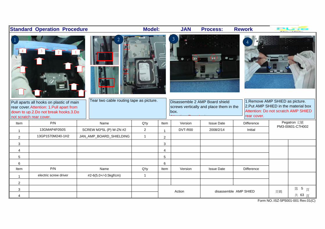
Pull aparts all hooks on plastic of mainrear cover.Attention: 1.Pull apart fromdown to up.2.Do not break hooks.3.Donot scratch rear cover.
1
124 3
Tear two cable routing tape as picture.
1
2
2
1.Remove AMP SHIED as picture.2.Put AMP SHIED in the material boxAttention: Do not scratch AMP SHIEDrear cover.
4
Disassemble 2 AMP Board shieldscrews vertically and place them in thebox.Attention: Do not mix screws
1 2
3
Standard Operation Procedure JAN Process: Rework
Item Name Q'ty Item Version Issue Date Difference
1 SCREW M3*5L (P) W-ZN #2 11 1 DVT-R00 2008/2/14 Initial
2 HP_JAN_REAR_SHIELD_ASM 1 2
3 3
4 4
5 5
6 6Item Name Q'ty Item Version Issue Date Difference
1 #2-6(5.0+/-0.5kgf/cm) 1
2
3 第 6 頁
4 共 63 頁
Form NO.:ISZ-5P5001-001 Rev.01(C)
Action disassemble rear shied 页碼
electric screw driver
P/N
Model:
P/N Pegatron 文號PM3-00601-C7H002
13GMAP4F050S
13GP157AM030-1H2
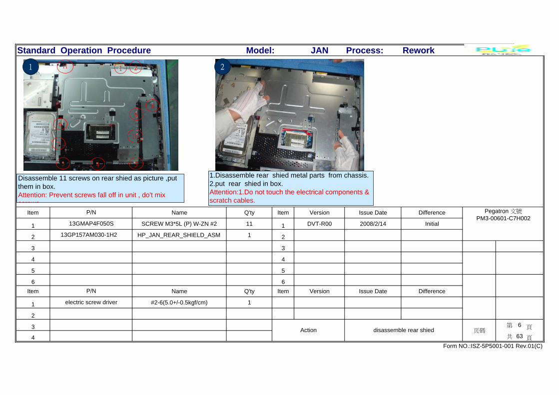
1.Disassemble rear shied metal parts from chassis.2.put rear shied in box.Attention:1.Do not touch the electrical components &scratch cables.
2
Disassemble 11 screws on rear shied as picture ,putthem in box.Attention: Prevent screws fall off in unit , do't mixscrews
11 1 2
3 4 5
10
9
8
6
7
1
Standard Operation Procedure JAN Process: Rework
Item Name Q'ty Item Version Issue Date Difference
1 1 DVT-R00 2008/2/14 Initial
2 2
3 3
4 4
5 5
6 6Item Name Q'ty Item Version Issue Date Difference
1
2
3 第 7 頁
4 共 63 頁
Form NO.:ISZ-5P5001-001 Rev.01(C)
Action pull out ODD SATA& power&switch cable 页碼
P/N
Model:
P/N Pegatron 文號PM3-00601-C7H002
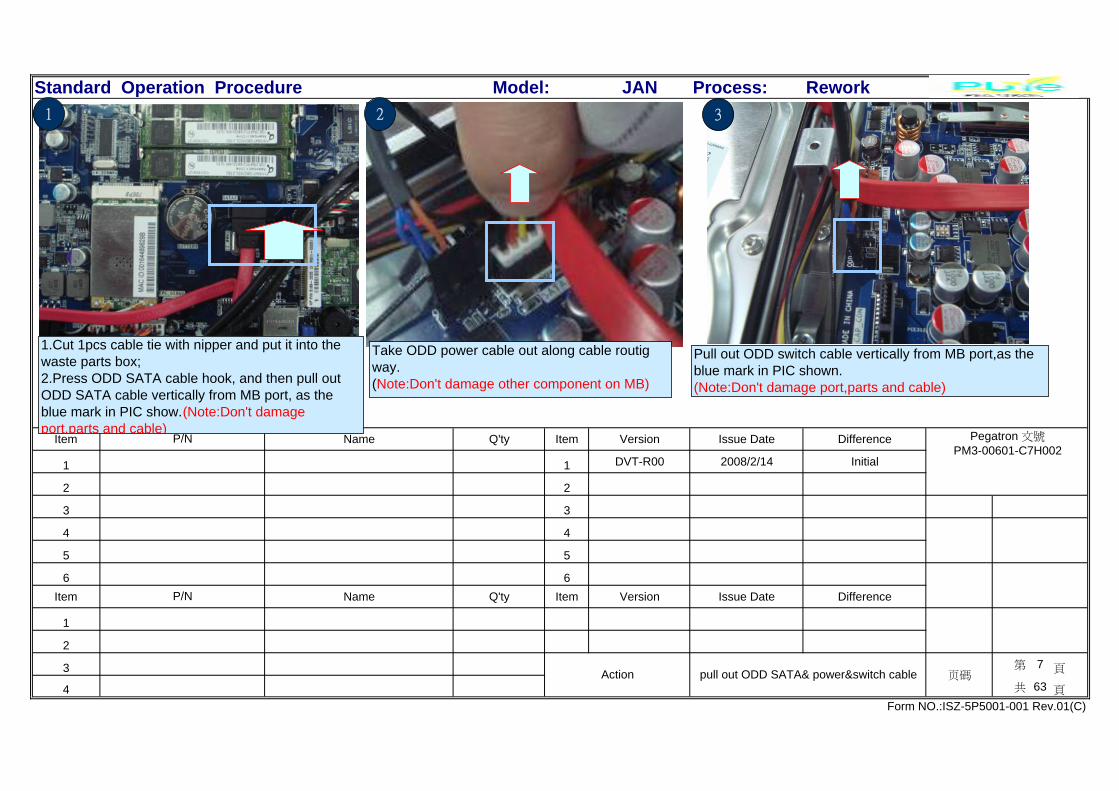
1.Cut 1pcs cable tie with nipper and put it into thewaste parts box;2.Press ODD SATA cable hook, and then pull outODD SATA cable vertically from MB port, as theblue mark in PIC show.(Note:Don't damageport,parts and cable)
1 2
Take ODD power cable out along cable routigway.(Note:Don't damage other component on MB)
Pull out ODD switch cable vertically from MB port,as theblue mark in PIC shown.(Note:Don't damage port,parts and cable)
3

Standard Operation Procedure JAN Process: Rework
Item Name Q'ty Item Version Issue Date Difference
1 SATA CBL 4P/7P TO 13P,L:410mm 1 1 DVT-R00 2008/2/14 Initial
2 W.H CBL 4P TO SW,L:250mm 1 2
3 3
4 4
5 5
6 6Item Name Q'ty Item Version Issue Date Difference
1
2
3 第 8 頁
4 共 63 頁
Form NO.:ISZ-5P5001-001 Rev.01(C)
Action take ODD 页碼
P/N
Model:
P/N Pegatron 文號PM3-00601-C7H002
1H2 S:14G000111800H2S:14G0
0H2 S:14G030037201H2 S:14G
Route ODD sata cable,ODD power cable and ODDswitch cable separatly.Note:Don't damage cable.
1
Un-lock the screw vertically with electricscrewdriver,and put it into parts box.Note:Don't damage parts and mix parts.
2
Take ODD and grasp it to right direction. Andthen make ODD frame out of .Note:Don't damage parts.
3
Standard Operation Procedure JAN Process: Rework
Item Name Q'ty Item Version Issue Date Difference
1 POWER_SWITCH_HOLDER 1 1 DVT-R00 2008/2/14 Initial
2 4P TO SW,L:250mm 1 2
3 3
4 4
5 5
6 6Item Name Q'ty Item Version Issue Date Difference
1
2
3 第 9 頁
4 共 63 頁
Form NO.:ISZ-5P5001-001 Rev.01(C)
Action disassemble ODD switch cable 页碼
P/N
S:14G030037201H2
Model:
P/N Pegatron 文號PM3-00601-C7H002
13GP1570P440-1H2
14G030037200H2
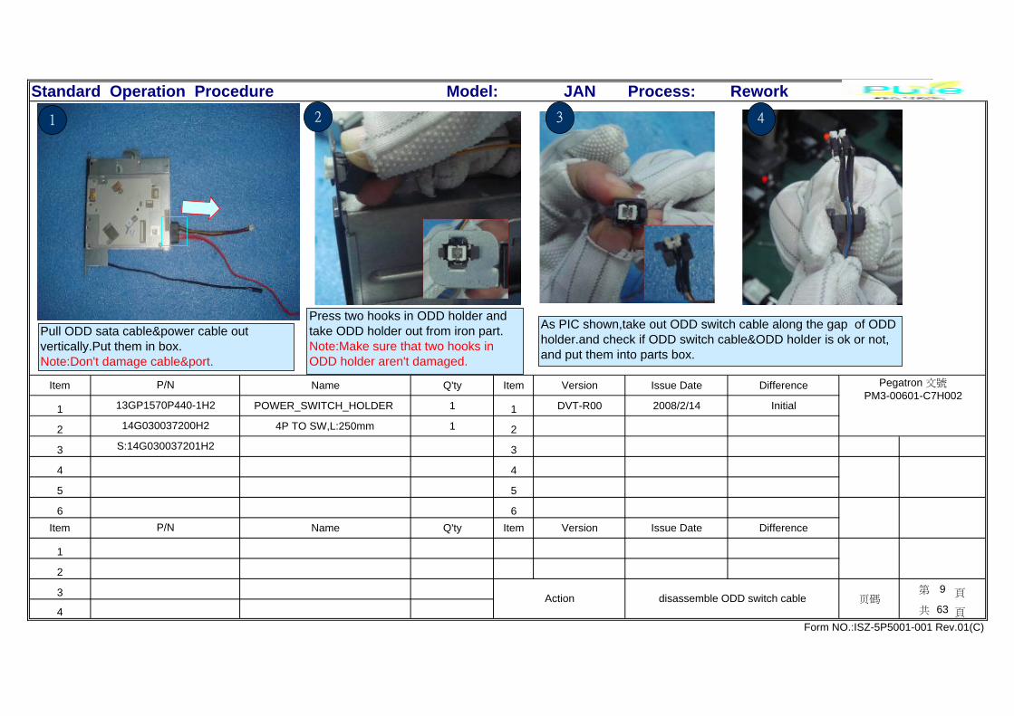
Pull ODD sata cable&power cable outvertically.Put them in box.Note:Don't damage cable&port.
1
As PIC shown,take out ODD switch cable along the gap of ODDholder.and check if ODD switch cable&ODD holder is ok or not,and put them into parts box.
Press two hooks in ODD holder andtake ODD holder out from iron part.Note:Make sure that two hooks inODD holder aren't damaged.
432
Standard Operation Procedure JAN Process: Rework
Item Name Q'ty Item Version Issue Date Difference
1 SCREW M2*2L (K) W-ZN #1 4 1 DVT-R00 2008/2/14 Initial
2 2
3 3
4 4
5 5
6 6Item Name Q'ty Item Version Issue Date Difference
1 #1(1.0±0.2kgf/cm) 1
2
3 第 10 頁
4 共 63 頁
Form NO.:ISZ-5P5001-001 Rev.01(C)
Action disassemble screw 页碼
Electric screw driver
P/N
Model:
P/N Pegatron 文號PM3-00601-C7H002
13GMAK3C020S
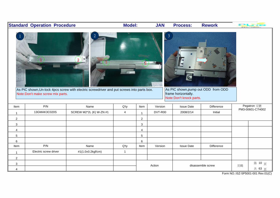
As PIC shown,Un-lock 4pcs screw with electric screwdriver and put screws into parts box.Note:Don't make screw mix parts.
1 2
1
21
2
As PIC shown,pump out ODD from ODDframe horizontally.Note:Don't knock parts.
3
Standard Operation Procedure JAN Process: Rework
Item Name Q'ty Item Version Issue Date Difference
1 JAN_ODD_CAGE_TOP 1 1 DVT-R00 2008/2/14 Initial
2 DVD S-SATA SM 8X/6X/5X/6X/6X 1 2
3 JAN_RB_SHIELD_GASKET_5 1 3
4 4
5 5
6 6Item Name Q'ty Item Version Issue Date Difference
1
2
3 第 11 頁
4 共 63 頁
Form NO.:ISZ-5P5001-001 Rev.01(C)
Action disassemble ODD 页碼
P/N
13GP1570T240-1H2
Model:
P/N Pegatron 文號PM3-00601-C7H002
13GP1570M070-1H2
17G141134002H2
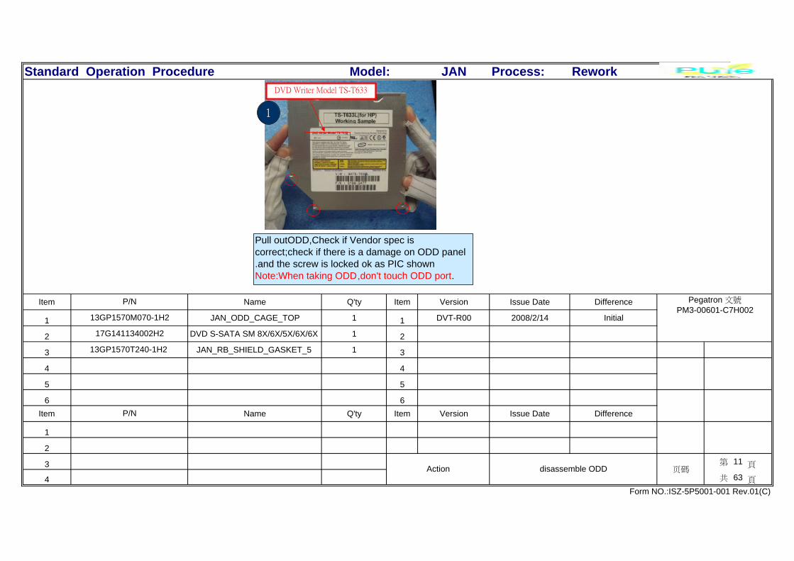
DVD Writer Model TS-T633
Pull outODD,Check if Vendor spec iscorrect;check if there is a damage on ODD panel.and the screw is locked ok as PIC shownNote:When taking ODD,don't touch ODD port.
1

Standard Operation Procedure JAN Process: Rework
Item Name Q'ty Item Version Issue Date Difference
1 1 DVT-R00 2008/2/14 Initial
2 2
3 3
4 4
5 5
6 6Item Name Q'ty Item Version Issue Date Difference
1 1
2
3 第 12 頁
4 共 63 頁
Form NO.:ISZ-5P5001-001 Rev.01(C)
Action cut cable ties &pull outHDD SATA cable 页碼
挟口钳
P/N
Model:
P/N Pegatron 文號PM3-00601-C7H002
1
1.Cut 1pcs cable tie with nipper and put it into the wasteparts box;Note:Don't damage cable;don't let cable scratchMB,Don't make tie-cable drop into unit.2.Route HDD sata cable as pic show.
Pull HDD sata cable from MB port out vertically.Note:Don't damage cable&port;and the hookshould be pressed entirely.
2 3
Cut 1 pcs tie-cable with nipper.and put itinto the waste parts box;Note:Don't make tie-cable drop into unit.
Route SATAcable

Standard Operation Procedure JAN Process: Rework
Item Name Q'ty Item Version Issue Date Difference
1 JAN_C_BKT 1 1 DVT-R00 2008/2/14 Initial
2 SCREW M3*5L (P) W-ZN #2 2 2
3 3
4 4
5 5
6 6Item Name Q'ty Item Version Issue Date Difference
1 #2 (5.0±0.5kgf/cm) 1
2
3 第 13 頁
4 共 63 頁
Form NO.:ISZ-5P5001-001 Rev.01(C)
Action disassemble cable& c-braket 页碼
Electric screw driver
P/N
Model:
P/N Pegatron 文號PM3-00601-C7H002
13GP1570M210-1H2
13GMAP4F050s
Disassemble 2 pcs screws on C-braket andput them into parts box.Note:Don't make screw mix parts.
2
1
2
Pull HDD power cable from MB connect out vertically. And routeHDD power cable as the yellow in PIC shown.Note:Don't damage cable.
1
Take C-braket parts off HDD;.Put it in parts stocks;
3

Standard Operation Procedure JAN Process: Rework
Item Name Q'ty Item Version Issue Date Difference
1 SATA CBL 7P TO 7P,L:210mm 1 1 DVT-R00 2008/2/14 Initial
2 2
3 3
4 ATA PWR CBL 4P TO 15P,L:170mm 1 4
5 5
6 SCREW M3*5L (P) W-ZN #2 1 6Item Name Q'ty Item Version Issue Date Difference
1 #2 (5.0±0.5kgf/cm) 1
2
3 第 14 頁
4 共 63 頁
Form NO.:ISZ-5P5001-001 Rev.01(C)
Action disassemble HDD& HDD sata &powercable 页碼
Electric screw driver
13GMAP4F050S P/N
S:14G000104612H2
1H2S:14G000110810H2S:14G0
Model:
P/N Pegatron 文號PM3-00601-C7H002
14G000104611H2
S:14G000104610H2
Disassemble 2 screws on HDD braketand put them into screw-box.Note:Don't make screw mix parts.
21
1.Take HDD edge,then push HDD upsideuntil take out HDD from base pan.2.Put HDD in parts stocks.
1.Pull out sata cable from HDD vertically;2.Hole HOD power cable port and pull outSATA cable vertically;Note:Don't damage cable,hook and port.
HDD Sata
HDD POWER
3

Standard Operation Procedure JAN Process: Rework
Item Name Q'ty Item Version Issue Date Difference
1 1 DVT-R00 2008/2/14 Initial
2 2
3 3
4 4
5 5
6 6Item Name Q'ty Item Version Issue Date Difference
1
2
3 第 15 頁
4 共 63 頁
Form NO.:ISZ-5P5001-001 Rev.01(C)
Action disassemble HDD 页碼
P/N
Model:
P/N Pegatron 文號PM3-00601-C7H002
Take HDD edge,and take HDD from theframe.
As PIC shown,disassemble 4 screw onframe and put screws into parts box.Note:Don't make screw mixed.
1
2
3
4
1 2
1.According to checklist,Check if HDD vendor&spec iscorrect;port&pin is ok;parts in PCB is ok.Note:when taking HDD,don't touch HDD PCB.
3 4
Standard Operation Procedure JAN Process: Rework
Item Name Q'ty Item Version Issue Date Difference
1 JAN_HDD_CAGE 1 1 DVT-R00 2008/2/14 Initial
2 JAN_IO_INSERT 1 2
3 3
4 4
5 5
6 6Item Name Q'ty Item Version Issue Date Difference
1
2
3 第 16 頁
4 共 63 頁
Form NO.:ISZ-5P5001-001 Rev.01(C)
Action put out HDD frame&IO_insert 页碼
P/N
Model:
P/N Pegatron 文號PM3-00601-C7H002
13GP1570M060-1H2
13GP157AP070-1H2
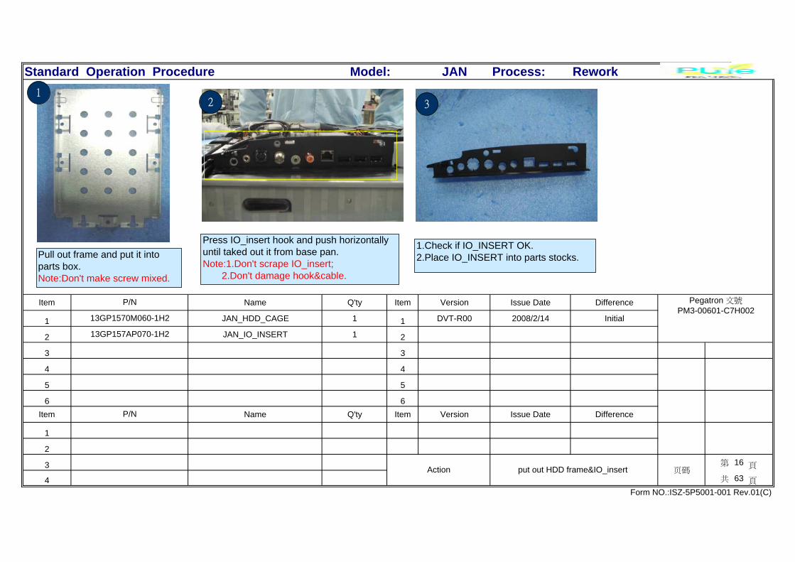
Pull out frame and put it intoparts box.Note:Don't make screw mixed.
12
Press IO_insert hook and push horizontallyuntil taked out it from base pan.Note:1.Don't scrape IO_insert; 2.Don't damage hook&cable.
1.Check if IO_INSERT OK.2.Place IO_INSERT into parts stocks.
3

Standard Operation Procedure JAN Process: Rework
Item Name Q'ty Item Version Issue Date Difference
1 1 DVT-R00 2008/2/14 Initial
2 2
3 3
4 4
5 5
6 6Item Name Q'ty Item Version Issue Date Difference
1
2
3 第 17 頁
4 共 63 頁
Form NO.:ISZ-5P5001-001 Rev.01(C)
Action DE I/O AUDIO&SIDE I/O USB cable& au 页碼
P/N
Model:
P/N Pegatron 文號PM3-00601-C7H002
2
As PIC show, route power cable &side I/O audiocable&side I/O USB cable.Note:Don't damage cable.
As PIC shown,pull side I/O,audio cable&side I/OUSB out vertically from M/B connector.Note:Don't damage cable&port.
side i/o audio
side i/o USB
1
Routing cable
AMP audio
As picture show,pull out the AMP audio cablefrom the M/B corresponding connect.Notice:Don't touch the electron component onM/B,don't cut off the cable.
3

Standard Operation Procedure JAN Process: Rework
Item Name Q'ty Item Version Issue Date Difference
1 1 DVT-R00 2008/2/14 Initial
2 2
3 3
4 4
5 5
6 6Item Name Q'ty Item Version Issue Date Difference
1
2
3 第 18 頁
4 共 63 頁
Form NO.:ISZ-5P5001-001 Rev.01(C)
Action pull out card reader usb&1394 cable 页碼
P/N
Model:
P/N Pegatron 文號PM3-00601-C7H002
card read USB
As picture show,pull out the card readUSB cable from the M/B correspondingcontent verticallyNotice:Don't touch theelectron component onM/B,don't cut off the cable.
1
As picture show,pull out the 1394 cable from the M/B corresponding connect vertically.Notice:Don't touch the electron component on M/B,don't cut off the cable.
card read1394
3 2
Cable-routing

Standard Operation Procedure JAN Process: Rework
Item Name Q'ty Item Version Issue Date Difference
1 1 DVT-R00 2008/2/14 Initial
2 2
3 3
4 4
5 5
6 6Item Name Q'ty Item Version Issue Date Difference
1
2
3 第 19 頁
4 共 63 頁
Form NO.:ISZ-5P5001-001 Rev.01(C)
Action WER&HOT START&VOLUME+POWER SWIT 页碼
P/N
Model:
P/N Pegatron 文號PM3-00601-C7H002
1.tear I pcs tape for cable routing,PuttheHOT START cable&VOLUME+POWERSWITCH cable&IR cable in order fromBASE PAN line trough.
To press down the main power connectclasp,make sure press down it ,pull out the MAINPOWER cable from the M/BCONNECT.Notice:Don't touch the electroncomponent on M/B don't cut off the cable
Pull out the HOT STARTcable&VOLUMN+POWER SWITCH cable&IRcable from the M/B conespondingcontent.Notice:Don't touch the electron componenton M/B,don't cut off the cable.
VOLUME cable IRcablehot start cable
321
Standard Operation Procedure JAN Process: Rework
Item Name Q'ty Item Version Issue Date Difference
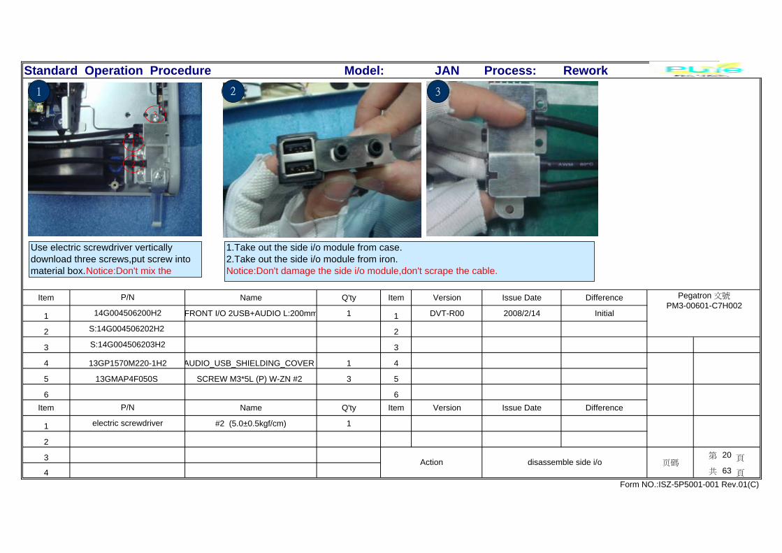
1 FRONT I/O 2USB+AUDIO L:200mm 1 1 DVT-R00 2008/2/14 Initial
2 2
3 3
4 AUDIO_USB_SHIELDING_COVER 1 4
5 SCREW M3*5L (P) W-ZN #2 3 5
6 6Item Name Q'ty Item Version Issue Date Difference
1 #2 (5.0±0.5kgf/cm) 1
2
3 第 20 頁
4 共 63 頁
Form NO.:ISZ-5P5001-001 Rev.01(C)
Action disassemble side i/o 页碼
electric screwdriver
P/N
S:14G004506203H2
13GP1570M220-1H2
13GMAP4F050S
Model:
P/N Pegatron 文號PM3-00601-C7H002
14G004506200H2
S:14G004506202H2
Use electric screwdriver verticallydownload three screws,put screw intomaterial box.Notice:Don't mix the
1
2
1
3
1.Take out the side i/o module from case.2.Take out the side i/o module from iron.Notice:Don't damage the side i/o module,don't scrape the cable.
32

Standard Operation Procedure JAN Process: Rework
Item Name Q'ty Item Version Issue Date Difference
1 SCREW M3*5L (P) W-ZN #2 3 1 DVT-R00 2008/2/14 Initial
2 2
3 3
4 4
5 5
6 6Item Name Q'ty Item Version Issue Date Difference
1 #2 (5.0±0.5kgf/cm) 1
2
3 第 21 頁
4 共 63 頁
Form NO.:ISZ-5P5001-001 Rev.01(C)
Action disassemble Card reader 页碼
electric screwdriver
P/N
Model:
P/N Pegatron 文號PM3-00601-C7H002
13GMAP4F050S
1
As picture show,use electricscrewdriver download two screws.Notice:Don't strike.
2
2
1.To pull apart the iron from the clasp aspicture with hands,take out the iron from Cardreader,confirm the clasp not crack,not out ofshape.2 C fi th bl d bl &VOLUMN bl
As picture show,use electric screwdriverdownload one screw,put screw intomaterial box.Notice:Don't strike,don't mixthe screw,don't let screw fall to the case.
1
2
1
3

Standard Operation Procedure JAN Process: Rework
Item Name Q'ty Item Version Issue Date Difference
1 CR USB2.0A 5IN1 JAN 1 1 DVT-R00 2008/2/14 Initial
2 CR USB2.0A 5IN1 JAN 1 2
3 CR USB2.0A 5IN1 JAN 1 3
4 JAN_CARD_READER SHIELDING 1 4
5 WH CBL 10P TO 4/6P C/R,L:430mm 1 5
6 6Item Name Q'ty Item Version Issue Date Difference
1
2
3 第 22 頁
4 共 63 頁
Form NO.:ISZ-5P5001-001 Rev.01(C)
Action disassemble card reader&card reader shieding 页碼
S:14G030037001H2P/N
S:04G540004520H2
13GP1570M200-1H2
14G030037000H2
Model:
P/N Pegatron 文號PM3-00601-C7H002
04G540004510H2
S:04G540004500H2
卡勾
The card reader cable have a blackconnecting,pull out it from card readertrough.put in stork.Notice:Handle the edgeof the card readder PCB,don't touch theelectronic component on the card.
32
1.Take down the Card reader module from case, as picture1.2 position shown, let the card reader go around the 1clasp, and pull out it above 2&3.Notice:Don"t press the cableand scrape PCB.Spring and clasp not out of shape.2.Confirm the HOT cable to take line under the Card reader,go around the screw.
1
1 2 3
1
Take out the card reader&card reader shieding,put instork.Notice:Handle the edge of the card readderPCB,don't touch the electronic component on thecard
4

Standard Operation Procedure JAN Process: Rework
Item Name Q'ty Item Version Issue Date Difference
1 SCREW M2*3.5L (K) W-ZN #1 2 1 DVT-R00 2008/2/14 Initial
2 2
3 3
4 4
5 5
6 6Item Name Q'ty Item Version Issue Date Difference
1 #2-6(1.0+//0.2kgf/cm) 1
2
3 第 23 頁
4 共 63 頁
Form NO.:ISZ-5P5001-001 Rev.01(C)
Action disassemble TV card cable 页碼
electric screwdriver
P/N
Model:
P/N Pegatron 文號PM3-00601-C7H002
13GMAK3C035S
Confirm AV input & TV terminal cable spare part take theline side by two screws, and take the cable into the iron.Notice:Don't relax the TV cable,don"t scrape the cable.
21
Take out the TV terminal cable from the TV card.Notice:Handle the edge of the card,don"t touch theelectron component and the gold finger.
TV terminal
Use the electric screwdriver to unloadtwo(2*3.5L L) screws vertically.Notice:Don't strike.
3
1
2
Standard Operation Procedure JAN Process: Rework
Item Name Q'ty Item Version Issue Date Difference
1 1 DVT-R00 2008/2/14 Initial
2 2
3 3
4 4
5 5
6 6Item Name Q'ty Item Version Issue Date Difference
1
2
3 第 24 頁
4 共 63 頁
Form NO.:ISZ-5P5001-001 Rev.01(C)
Action disassemble TV card 页碼
P/N
Model:
P/N Pegatron 文號PM3-00601-C7H002
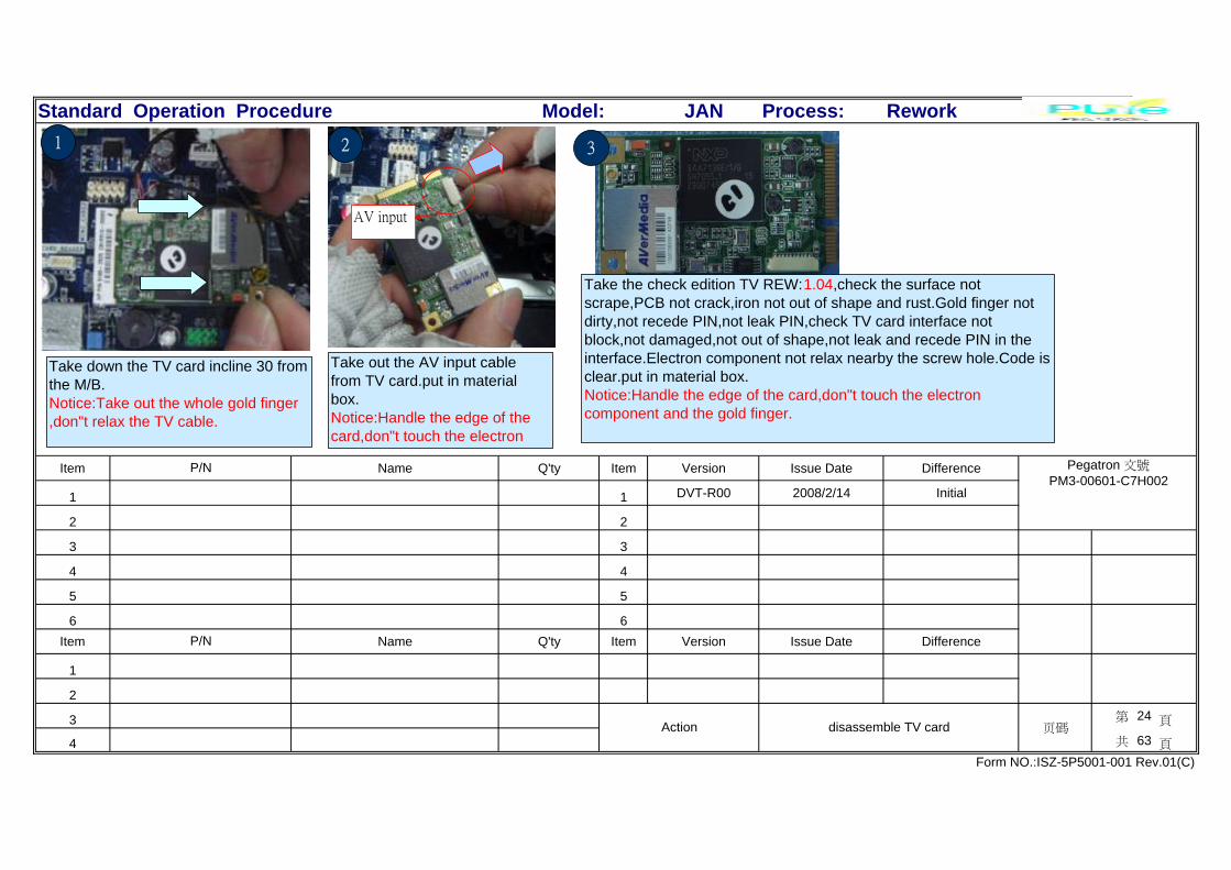
Take out the AV input cablefrom TV card.put in materialbox.Notice:Handle the edge of thecard,don"t touch the electron
AV input
2
Take down the TV card incline 30 fromthe M/B.Notice:Take out the whole gold finger,don"t relax the TV cable.
1 3
Take the check edition TV REW:1.04,check the surface notscrape,PCB not crack,iron not out of shape and rust.Gold finger notdirty,not recede PIN,not leak PIN,check TV card interface notblock,not damaged,not out of shape,not leak and recede PIN in theinterface.Electron component not relax nearby the screw hole.Code isclear.put in material box.Notice:Handle the edge of the card,don"t touch the electroncomponent and the gold finger.
Standard Operation Procedure JAN Process: Rework
Item Name Q'ty Item Version Issue Date Difference
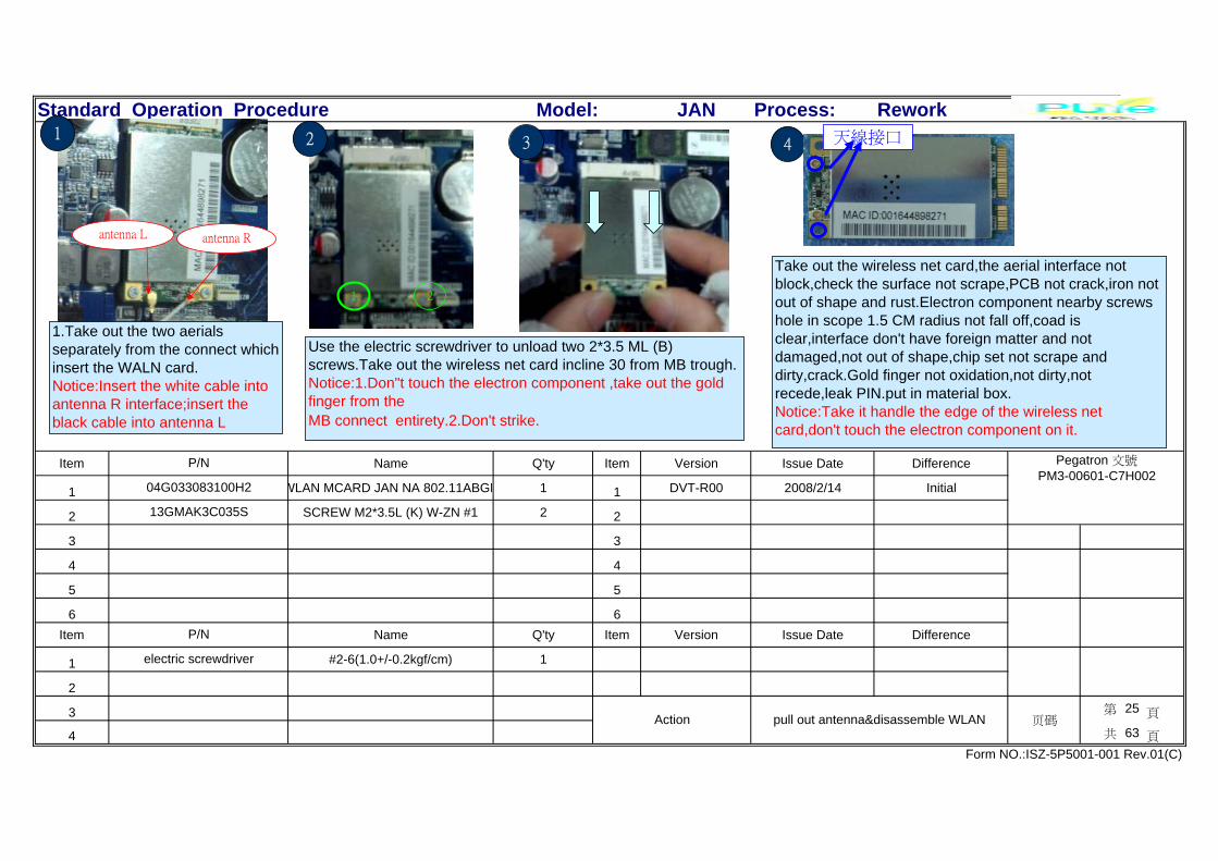
1 WLAN MCARD JAN NA 802.11ABGN 1 1 DVT-R00 2008/2/14 Initial
2 SCREW M2*3.5L (K) W-ZN #1 2 2
3 3
4 4
5 5
6 6Item Name Q'ty Item Version Issue Date Difference
1 #2-6(1.0+/-0.2kgf/cm) 1
2
3 第 25 頁
4 共 63 頁
Form NO.:ISZ-5P5001-001 Rev.01(C)
Action pull out antenna&disassemble WLAN 页碼
electric screwdriver
P/N
Model:
P/N Pegatron 文號PM3-00601-C7H002
04G033083100H2
13GMAK3C035S
antenna L antenna R
1.Take out the two aerialsseparately from the connect whichinsert the WALN card.Notice:Insert the white cable intoantenna R interface;insert theblack cable into antenna L
1
Take out the wireless net card,the aerial interface notblock,check the surface not scrape,PCB not crack,iron notout of shape and rust.Electron component nearby screwshole in scope 1.5 CM radius not fall off,coad isclear,interface don't have foreign matter and notdamaged,not out of shape,chip set not scrape anddirty,crack.Gold finger not oxidation,not dirty,notrecede,leak PIN.put in material box.Notice:Take it handle the edge of the wireless netcard,don't touch the electron component on it.
Use the electric screwdriver to unload two 2*3.5 ML (B)screws.Take out the wireless net card incline 30 from MB trough.Notice:1.Don"t touch the electron component ,take out the goldfinger from theMB connect entirety.2.Don't strike.
43
1 2
2 天線接口

Standard Operation Procedure JAN Process: Rework
Item Name Q'ty Item Version Issue Date Difference
1 CPU THERMAL MODULE 1 1 DVT-R00 2008/2/14 Initial
2 SCREW M3*13L (B) 1 2
3 3
4 4
5 5
6 6Item Name Q'ty Item Version Issue Date Difference
1 #2 (5.0±0.5kgf/cm) 1
2
3 第 26 頁
4 共 63 頁
Form NO.:ISZ-5P5001-001 Rev.01(C)
Action diassemble CPU H/S&pull out cable 页碼
electric screwdriver
P/N
Model:
P/N Pegatron 文號PM3-00601-C7H002
13G075199000H2
13GMAB3F130S
Use the electric screwdriver to unload seven screwsfixed to CPU H/S&CPU.Notice:Don't touch electron component on M/B.
5
3 2
4
7
1
6
1
VGA H/S CABLECPU H/S CABLE
2
Take out the CPU H/S main power cable fromMB_Fan1 interface.
3
Take out CPU H/S,put it in box.

Standard Operation Procedure JAN Process: Rework
Item Name Q'ty Item Version Issue Date Difference
1 SCREW M3*13L (B) W-Zn #2 3 1 DVT-R00 2008/2/14 Initial
2 JAN MXM THERMAL MODULE KIT 1 2
3 3
4 4
5 5
6 6Item Name Q'ty Item Version Issue Date Difference
1 #2 (5.0±0.5kgf/cm) 1
2 #1-6(1.2±0.2kgf/cm) 1
3 第 27 頁
4 共 63 頁
Form NO.:ISZ-5P5001-001 Rev.01(C)
Action disassemble H/S 页碼
electric screwdriver
electric screwdriver
P/N
Model:
P/N Pegatron 文號PM3-00601-C7H002
13GMAB3F130S
13G075199010H2
Use the electric screwdriver to unload sevenscrews fixed VGA H/S&VGA.Put screws intomaterial box.Notice:Don't touch electron component onM/B.Don't mix the screw.
Take out the VGA H/S power cord from MB_Fan2(V)interface.Notice:Don't crack the cable.
2
6
57
1
2 3
4
1
1.Take out VGA H/S,2.Put it into material box.
3

Standard Operation Procedure JAN Process: Rework
Item Name Q'ty Item Version Issue Date Difference
1 G98/MXM/256M/HP(P621) 1 1 DVT-R00 2008/2/14 Initial
2 SCREW M2*3.5L (K) W-ZN #1 2 2
3 3
4 4
5 5
6 6Item Name Q'ty Item Version Issue Date Difference
1 #1-6(1.0±0.2kgf/cm) 1
2
3 第 28 頁
4 共 63 頁
Form NO.:ISZ-5P5001-001 Rev.01(C)
Action disassemble VGA 页碼
electric screwdriver
P/N
Model:
P/N Pegatron 文號PM3-00601-C7H002
80-C1D0W0-H0A01
13GMAK3C035S
1
Take down the VGA card incline 30 from theM/B.Notice:Don't touch the electron component onthe card,don't strike.
1 2
Use electric screwdriver to unload twoscrews and put it into material box.Notice:Don't strike,don't mix the screw.
23
Take out VGA card into material box.Notice:Don't touch the electroncomponent on the card.Don't touch goldfinger.

Standard Operation Procedure JAN Process: Rework
Item Name Q'ty Item Version Issue Date Difference
1 Jan inverter air box 1 1 DVT-R00 2008/2/14 Initial
2 2
3 3
4 4
5 5
6 6Item Name Q'ty Item Version Issue Date Difference
1
2
3 第 29 頁
4 共 63 頁
Form NO.:ISZ-5P5001-001 Rev.01(C)
Action disassemble inverter air box 页碼
P/N
Model:
P/N Pegatron 文號PM3-00601-C7H002
13GP1570T140-1H2
1.Pull out inverter cable from AMP card connect vertically.Note:Don't break cable&connector.2.Route inverter cable(as green part).
21
Take director cover away from BASEPAN.NOTE:Don't break director cover .Put it on material temporary storage.
6pin
bl

Standard Operation Procedure JAN Process: Rework
Item Name Q'ty Item Version Issue Date Difference
1 1 DVT-R00 2008/2/14 Initial
2 2
3 3
4 4
5 5
6 6Item Name Q'ty Item Version Issue Date Difference
1
2
3 第 30 頁
4 共 63 頁
Form NO.:ISZ-5P5001-001 Rev.01(C)
Action pull out cable 页碼
P/N
Model:
P/N Pegatron 文號PM3-00601-C7H002
3pin
bl
1.Pull out inverter cable from M/B CONNECT vertically.Note:Don't damage cable&connector.2.Tear tape,put it in discarding box.Note:Don't make tape fall off in unit.
1
Press hook,pull out inverter cable vertically.Note:Don't break cable&connector.
2
Standard Operation Procedure JAN Process: Rework
Item Name Q'ty Item Version Issue Date Difference
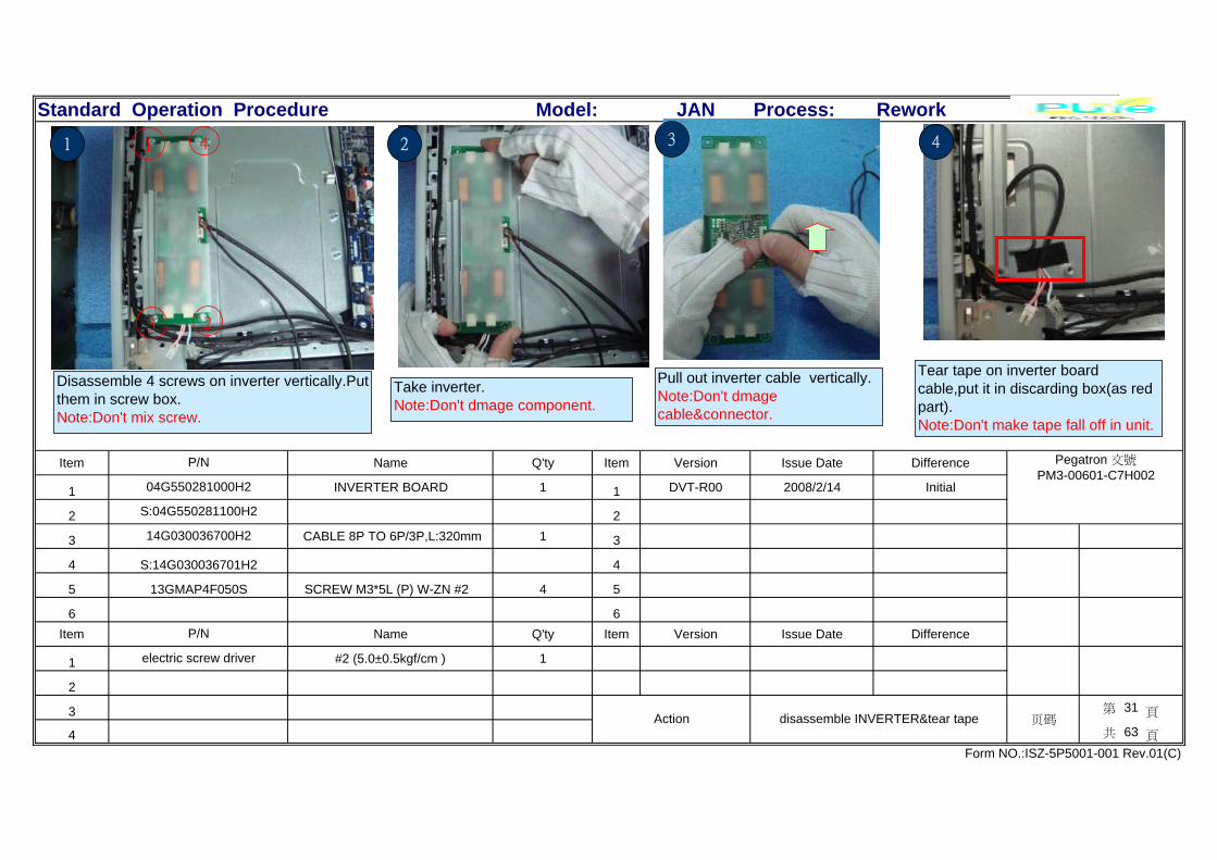
1 INVERTER BOARD 1 1 DVT-R00 2008/2/14 Initial
2 2
3 CABLE 8P TO 6P/3P,L:320mm 1 3
4 4
5 SCREW M3*5L (P) W-ZN #2 4 5
6 6Item Name Q'ty Item Version Issue Date Difference
1 #2 (5.0±0.5kgf/cm ) 1
2
3 第 31 頁
4 共 63 頁
Form NO.:ISZ-5P5001-001 Rev.01(C)
Action disassemble INVERTER&tear tape 页碼
electric screw driver
P/N
14G030036700H2
S:14G030036701H2
13GMAP4F050S
Model:
P/N Pegatron 文號PM3-00601-C7H002
04G550281000H2
S:04G550281100H2
Pull out inverter cable vertically.Note:Don't dmagecable&connector.
3
Take inverter.Note:Don't dmage component.
Disassemble 4 screws on inverter vertically.Putthem in screw box.Note:Don't mix screw.
1
23
4 21 4
Tear tape on inverter boardcable,put it in discarding box(as redpart).Note:Don't make tape fall off in unit.

Standard Operation Procedure JAN Process: Rework
Item Name Q'ty Item Version Issue Date Difference
1 40P TO 30P LVDS,L:200mm 1 1 DVT-R00 2008/2/14 Initial
2 2
3 3
4 4
5 5
6 6Item Name Q'ty Item Version Issue Date Difference
1
2
3 第 32 頁
4 共 63 頁
Form NO.:ISZ-5P5001-001 Rev.01(C)
Action tear tape&Pull out LVDS cable 页碼
P/N
Model:
P/N Pegatron 文號PM3-00601-C7H002
14G030024510H2
S:14G030024511H2
Tear tape on LVDS cable,put it in discardingbox(as red part).Note:Don't make tape fall off in unit.
4For no VGA For VGA1 2
Tear tape on LVDS cable,put it in discardingbox(as red part).Note:Don't make tape fall off in unit.
Hold LVDS connectot(as red circle).Pull out LVDS cable vertically at the sametime.Note:Don't pull out LVDS cable directly.
3

Standard Operation Procedure JAN Process: Rework
Item Name Q'ty Item Version Issue Date Difference
1 1 DVT-R00 2008/2/14 Initial
2 2
3 3
4 4
5 5
6 6Item Name Q'ty Item Version Issue Date Difference
1
2
3 第 33 頁
4 共 63 頁
Form NO.:ISZ-5P5001-001 Rev.01(C)
Action ll outLVDS&MIC cable&CAMER cable&TS ca 页碼
P/N
Model:
P/N Pegatron 文號PM3-00601-C7H002
Hold LVDS connector(as red circle).Pull out LVDS cable vertically at the same time.Note:Don't pull out directly LVDS cable & don'tbreak the cable.
1
Pull out MIC cable from M/B CONNECTvertically(as pic).Note:Don't damage cable&connector.
2MIC
bl
CAMERA cable
TS cable(M/B)
1.Pull out CAMER cable from M/B vertically2.Pull out TS cable from M/B vertically.Note:Don't break cable&connector.
3

Standard Operation Procedure JAN Process: Rework
Item Name Q'ty Item Version Issue Date Difference
1 1 DVT-R00 2008/2/14 Initial
2 2
3 3
4 4
5 5
6 6Item Name Q'ty Item Version Issue Date Difference
1
2
3 第 34 頁
4 共 63 頁
Form NO.:ISZ-5P5001-001 Rev.01(C)
Action MBEINT cable&Bluetooth cable (M/B)&Event 页碼
P/N
Model:
P/N Pegatron 文號PM3-00601-C7H002
Hold BLUE TOOTH cable connector,piull out BLUETOOTH cable M/B vertically.Note:Don't break cable&connector.
1.Tear 2 tape on ambient light cable,put it indiscarding box(as red part).Note:Don't make tape fall off in unit .2.Pull out ambient light cable from AMBENTconnector(as yellow part).Note: Don't break &scratch cable.
BLUE TOOTH Cable
ambient
light card
cable
1 2
1.Tear tape,put it in discarding box(as red part).2.Pull out EVENT LED cable from M/B vertically(as yellowpart).Note:Don't break cable&connector.
3
Event LED cable
Standard Operation Procedure JAN Process: Rework
Item Name Q'ty Item Version Issue Date Difference
1 SCREW M3*5L (P) W-ZN #2 6 1 DVT-R00 2008/2/14 Initial
2 2
3 3
4 4
5 5
6 6Item Name Q'ty Item Version Issue Date Difference
1 #2 (5.0+/-0.5kgf/cm) 1
2
3 第 35 頁
4 共 63 頁
Form NO.:ISZ-5P5001-001 Rev.01(C)
Action take MB 页碼
electric screw driver
P/N
Model:
P/N Pegatron 文號PM3-00601-C7H002
13GMAP4F050S
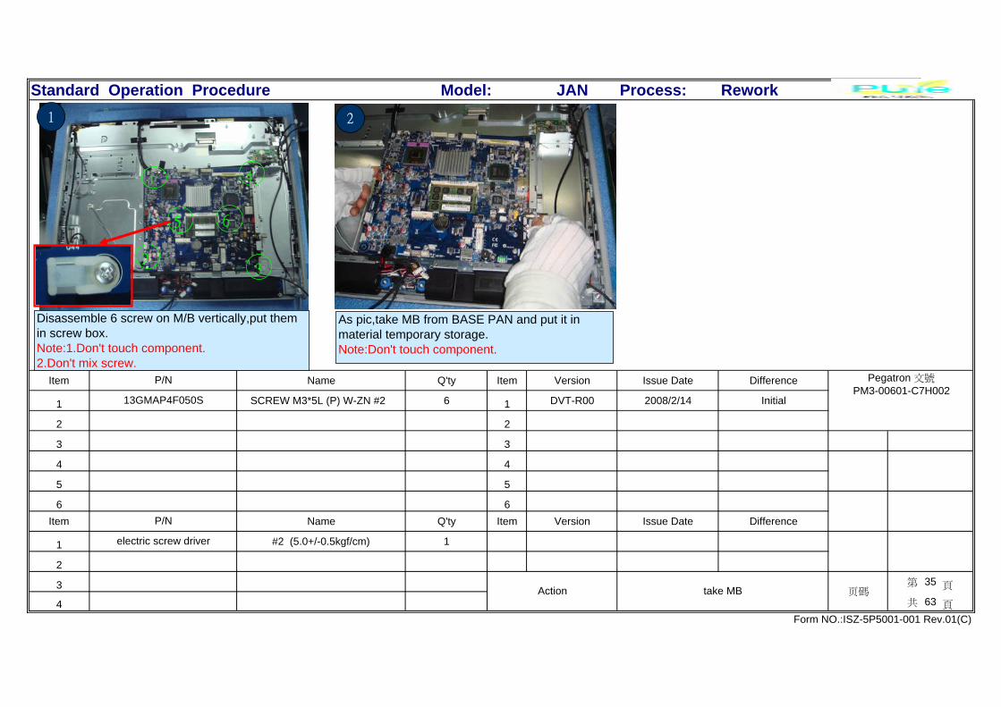
Disassemble 6 screw on M/B vertically,put themin screw box.Note:1.Don't touch component.2.Don't mix screw.
2
1
3
4
65
1 2
As pic,take MB from BASE PAN and put it inmaterial temporary storage.Note:Don't touch component.

Standard Operation Procedure JAN Process: Rework
Item Name Q'ty Item Version Issue Date Difference
1 1 DVT-R00 2008/2/14 Initial
2 2
3 3
4 4
5 5
6 6Item Name Q'ty Item Version Issue Date Difference
1
2
3 第 36 頁
4 共 63 頁
Form NO.:ISZ-5P5001-001 Rev.01(C)
Action disassemble DDR&CPU 页碼
P/N
Model:
P/N Pegatron 文號PM3-00601-C7H002
1.Press DDR hook until DDR spring (as pic)Note: Don't break hook.2.Hold DDR&pull out DDR at the same time,makesure DDR golden finger pull out entirety.3.put DDR in stork box.
1
pull out at same time
11
22
Make sure tool no dirty,nounusual thing, then take CPU onM/B .
Rotate 180
Lock screw on CPU card hook(aspic),rotate screw driver 180 degree.Note:Make sure it locked in the rightposition.
2 3
fool-
proof

Standard Operation Procedure JAN Process: Rework
Item Name Q'ty Item Version Issue Date Difference
1 MISR-CF/JAN/HP R1.02(5189-2525 1 1 DVT-R00 2008/2/14 Initial
2 2
3 JAN_CPU_BACKPLANE 1 3
4 4
5 5
6 6Item Name Q'ty Item Version Issue Date Difference
1
2
3 第 37 頁
4 共 63 頁
Form NO.:ISZ-5P5001-001 Rev.01(C)
Action disassemble CPU stanfd&M/B 页碼
P/N
13GP157AM040-1H2
Model:
P/N Pegatron 文號PM3-00601-C7H002
80-MIB304-G001P
S:80-MIB304-G002P
1
fool-proof
1.Take CPU from M/B.Note:Don't touch component,don't makeCPU fall off.2.Check PIN in the samelevel,nobroken&no foreign thing3.Put CPU in material temporary storage.
2
Take CPU stand from MB.Note:Don't touchcomponent.2.Put it in materialtemporary storage.
3
1.Take M/B(as pic),check version is R1.02.componentaround screw hole OK,IO connector is OK,confirmjumper&GMCH H/S position is right,PCB board noscratch,DDR PIN on M/B existed.Reverse M/B,check M/BPCB board not scratch.Note:Take M/B edge,don't touch electrion component.2 Put M/B in material temporary storage
Standard Operation Procedure JAN Process: Rework
Item Name Q'ty Item Version Issue Date Difference
1 1 DVT-R00 2008/2/14 Initial
2 2
3 3
4 4
5 5
6 6Item Name Q'ty Item Version Issue Date Difference
1
2
3 第 38 頁
4 共 63 頁
Form NO.:ISZ-5P5001-001 Rev.01(C)
Action tear tape 页碼
P/N
Model:
P/N Pegatron 文號PM3-00601-C7H002
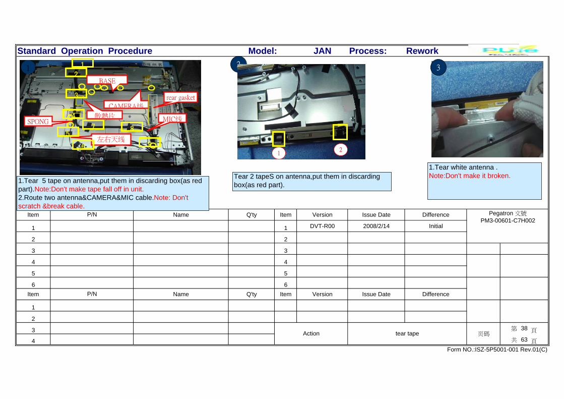
1.Tear 5 tape on antenna,put them in discarding box(as redpart).Note:Don't make tape fall off in unit.2.Route two antenna&CAMERA&MIC cable.Note: Don'tscratch &break cable.
2
Tear 2 tapeS on antenna,put them in discardingbox(as red part).
3
1.Tear white antenna .Note:Don't make it broken.
2
2
SPONG
左右天线
MIC线
CAMERA线
rear gasket
BASE
3
7 85
96
散熱片
1
4
1
12

Standard Operation Procedure JAN Process: Rework
Item Name Q'ty Item Version Issue Date Difference
1 WLAN ANTENNA-L 1 1 DVT-R00 2008/2/14 Initial
2 2
3 WLAN ANTENNA-R 1 3
4 4
5 5
6 6Item Name Q'ty Item Version Issue Date Difference
1
2
3 第 39 頁
4 共 63 頁
Form NO.:ISZ-5P5001-001 Rev.01(C)
Action disassemble antenna 页碼
P/N
14G154009100H2
S:14G154010000H2
Model:
P/N Pegatron 文號PM3-00601-C7H002
14G154009000H2
S:14G154010100H2
1
1.Route cable from BASE PAN.Note: Make sure don't scratchcable.2.Put it in material temporaryt
32
1.Check black antenna(left),confirm cablenot broken,no copperoutside,connerctor&antenna small cardOK.
1.Tear black antenna.Note:Don't make it broken.2.Route cable fron BASE PAN connector.Note: Don't scratch cable.

Standard Operation Procedure JAN Process: Rework
Item Name Q'ty Item Version Issue Date Difference
1 JAN SPEAKER 4W LEFT 1 1 DVT-R00 2008/2/14 Initial
2 JAN SPEAKER 4W RIGHT 1 2
3 SCREW M3*5L H=9.5 (B) W-ZN #2 A 2 3
4 SCREW M3*5L H=8 (B) B-ZN #2 A 2 4
5 5
6 6Item Name Q'ty Item Version Issue Date Difference
1 #2 (5.0±0.5kgf/cm) 1
2
3 第 40 頁
4 共 63 頁
Form NO.:ISZ-5P5001-001 Rev.01(C)
Action disassemble SPEAKER 页碼
electric screw driver
P/N
13GMAB4F145S
13GMAB4F130Z
Model:
P/N Pegatron 文號PM3-00601-C7H002
04G170032910H2
04G170032900H2
1.Dissamble 4screws on left/right speaker vertically.Note:Don't touch speaker eardrum part.2.Take left/right speaker,check speaker no broken ,nodeformed.3.Put it in material temporary stockage.
2
1 2 4 3
1
speaker L
speaker R
Pull out speaker cable from AMP connectorvertically.Note:Don't damage cable&connector.
Standard Operation Procedure JAN Process: Rework
Item Name Q'ty Item Version Issue Date Difference
1 SCREW M3*5L (P) W-ZN #2 2 1 DVT-R00 2008/2/14 Initial
2 2
3 3
4 4
5 5
6 6Item Name Q'ty Item Version Issue Date Difference
1 #2 (5.0±0.5kgf/cm) 1
2
3 第 41 頁
4 共 63 頁
Form NO.:ISZ-5P5001-001 Rev.01(C)
Action disassemble FFC cable& screw 页碼
electric screw driver
P/N
Model:
P/N Pegatron 文號PM3-00601-C7H002
13GMAP4F050S
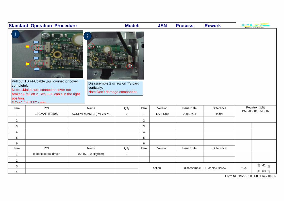
Disassemble 2 screw on TS cardvertically.Note:Don't damage component.
1
2
2
Pull out TS FFCcable ,pull connector covercompletely.Note:1.Make sure connector cover notbroken& fall off.2.Two FFC cable in the rightposition.3 Don't fold FFC cable
1
Standard Operation Procedure JAN Process: Rework
Item Name Q'ty Item Version Issue Date Difference
1 1 DVT-R00 2008/2/14 Initial
2 JAN TOUCH SCREEN 22' 1 2
3 3
4 5P TO 5P T/S,L:100mm 1 4
5 5
6 6Item Name Q'ty Item Version Issue Date Difference
1
2
3 第 42 頁
4 共 63 頁
Form NO.:ISZ-5P5001-001 Rev.01(C)
Action disassemblr TS card 页碼
P/N
14G030010220H2
S:14G030010221H2
Model:
P/N Pegatron 文號PM3-00601-C7H002
18G302200000H2
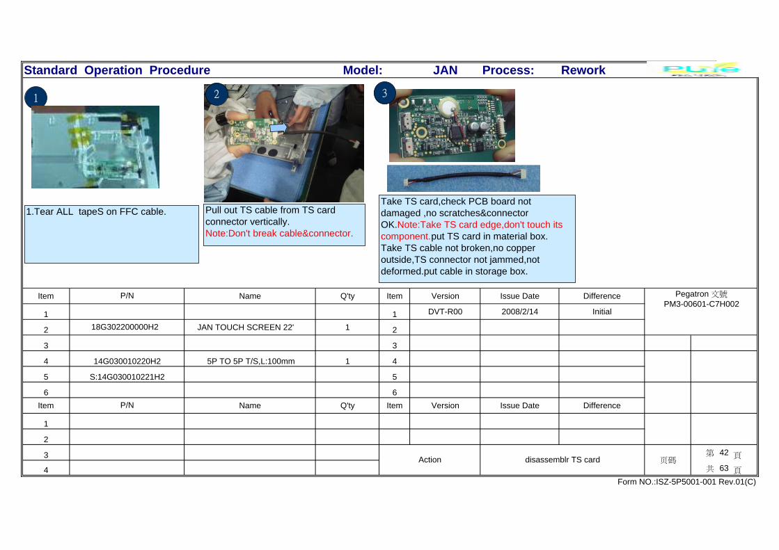
Pull out TS cable from TS cardconnector vertically.Note:Don't break cable&connector.
2
1.Tear ALL tapeS on FFC cable.
1 3
Take TS card,check PCB board notdamaged ,no scratches&connectorOK.Note:Take TS card edge,don't touch itscomponent.put TS card in material box.Take TS cable not broken,no copperoutside,TS connector not jammed,notdeformed.put cable in storage box.

Standard Operation Procedure JAN Process: Rework
Item Name Q'ty Item Version Issue Date Difference
1 AMP-JAN/HP R1.02B 1 1 DVT-R00 2008/2/14 Initial
2 6P TO 6P,L:50mm AMPpower cable 1 2
3 3
4 SCREW M3*5L (P) W-ZN #2 3 4
5 O 10P AMP,L:220mm AMP AUDIO 1 5
6 6Item Name Q'ty Item Version Issue Date Difference
1 #2 (5.0±0.5kgf/cm) 1
2
3 第 43 頁
4 共 63 頁
14G000608900H2
S:14G000608901H2
Form NO.:ISZ-5P5001-001 Rev.01(C)
Action disassemble AMP card 页碼
electric screw driver
S:14G030036501H2 P/N
13GMAP4F050S
14G030036500H2
Model:
P/N Pegatron 文號PM3-00601-C7H002
80-C1BJY4-00A01
Disassemble 3 screw on AMP card vertically(as pic)Put them in screw box .Note:Don't mix screws.
3 2
1
1
Take AMP card ,pull out AMP Audiocable vertically.Note:Take PCB board edge,don'tdamage cable&connector.
2
Pull out AMP Audio power cablevertically(as pic).Note:Take PCB board edge,don'tdamage cable&connector.
3 4
1.Take AMP CARD,checkPCB boardno broken,no scratch,componentaround screw hole no fall off.2.Put it in material temporary stockage.

Standard Operation Procedure JAN Process: Rework
Item Name Q'ty Item Version Issue Date Difference
1 SCREW M3*5L (P) W-ZN #2 (white) 6 1 DVT-R00 2008/2/14 Initial
2 CREW M3*6L D5.5 (P) B-ZN #2(blac 6 2
3 3
4 4
5 5
6 6Item Name Q'ty Item Version Issue Date Difference
1 #2 (5.0±0.5kgf/cm) 1
2
3 第 44 頁
4 共 63 頁
Form NO.:ISZ-5P5001-001 Rev.01(C)
Action disassemble BASE 页碼
electric screw driver
P/N
Model:
P/N Pegatron 文號PM3-00601-C7H002
13GMAP4F050S
13GMCP4F061Z
1 2
3 45
6
7
8
9
10
11
12
Disassemble 12 screws vertically on BASE (as pic).Put themin screw box .Note:Don't mix screws. Two operators hold BASE PAN,route power switch&Hot start Volume&IR &Blue tooth cable,lift
base pan from unit.Note:Route camera&led cable,pass POWER Switch &Hot start&Volume&IRcable&bluetooth cable through base pan hole.Don't press &scratch cable.
21

Standard Operation Procedure JAN Process: Rework
Item Name Q'ty Item Version Issue Date Difference
1 SCREW M3*4L (B) W-ZN #2 4 1 DVT-R00 2008/2/14 Initial
2 2
3 3
4 4
5 5
6 6Item Name Q'ty Item Version Issue Date Difference
1 #2 (5.0+/-0.5kgf/cm) 1
2
3 第 45 頁
4 共 63 頁
Form NO.:ISZ-5P5001-001 Rev.01(C)
Action disassemble LCD 页碼
electric screw driver
P/N
Model:
P/N Pegatron 文號PM3-00601-C7H002
13GMAB4F040S
Two operator disassemble 2 screw on Base pan left/rightside,put screws in screw box.Note:Don't make screws mixed.Diassembling order :first onenext to foot (circle2),second one is on LCD (circle1).
1
21
12right
left 21
12right
left
12right
1
Two operator hold base pan,route inverter cable&FFC cablethrough corresponding base pan hole,then separate base panand LCD.Note:Don't scratch cable.
2
Standard Operation Procedure JAN Process: Rework
Item Name Q'ty Item Version Issue Date Difference
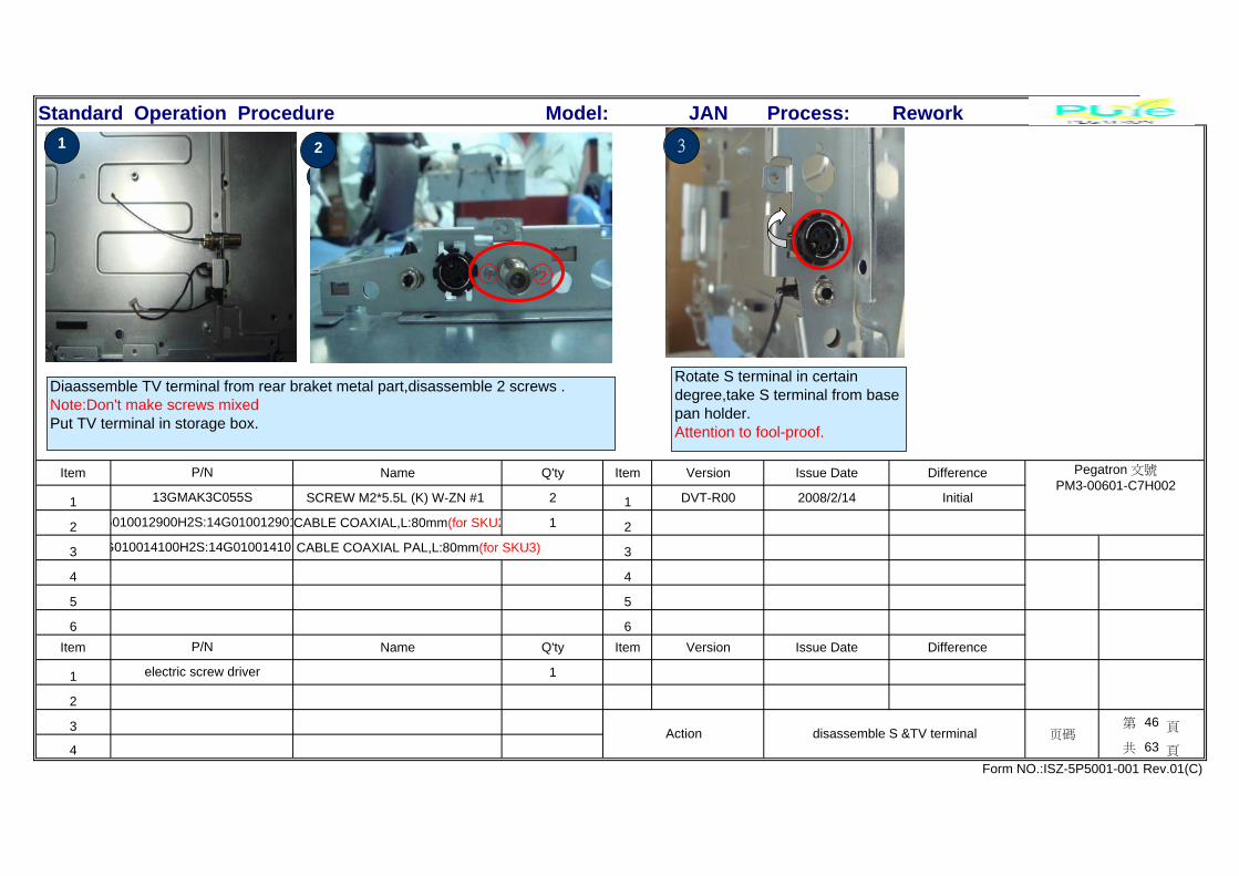
1 SCREW M2*5.5L (K) W-ZN #1 2 1 DVT-R00 2008/2/14 Initial
2 CABLE COAXIAL,L:80mm(for SKU2 1 2
3 CABLE COAXIAL PAL,L:80mm(for SKU3) 3
4 4
5 5
6 6Item Name Q'ty Item Version Issue Date Difference
1 1
2
3 第 46 頁
4 共 63 頁
Form NO.:ISZ-5P5001-001 Rev.01(C)
Action disassemble S &TV terminal 页碼
electric screw driver
P/N
G010014100H2S:14G010014101
Model:
P/N Pegatron 文號PM3-00601-C7H002
13GMAK3C055S
G010012900H2S:14G010012901
Diaassemble TV terminal from rear braket metal part,disassemble 2 screws .Note:Don't make screws mixedPut TV terminal in storage box.
2
1 2
21
Rotate S terminal in certaindegree,take S terminal from basepan holder.Attention to fool-proof.
3

Standard Operation Procedure JAN Process: Rework
Item Name Q'ty Item Version Issue Date Difference
1 TO 4P DIN/AUD,L80mm(for SKU2&S 1 1 DVT-R00 2008/2/14 Initial
2 2
3 3
4 4
5 5
6 6Item Name Q'ty Item Version Issue Date Difference
1 2#, 6cm, 1.5±0.5kgf/cm 1
2
3 第 47 頁
4 共 63 頁
Form NO.:ISZ-5P5001-001 Rev.01(C)
Action disassemble AUDIO terminal 页碼
electric screw driver
P/N
Model:
P/N Pegatron 文號PM3-00601-C7H002
14G010012800H2
S:14G010012801H2
Assemble AUDIOconnector on rear braketmetal part, disassemblescrew circle with electricscrew driver.
32
1.Disassemble screw circle on AUDIO cable .Make sure itexisted.2.Put it in material temporary stockage.
fool-proof
Take S terminal from base pan(as pic).
1
Standard Operation Procedure JAN Process: Rework
Item Name Q'ty Item Version Issue Date Difference
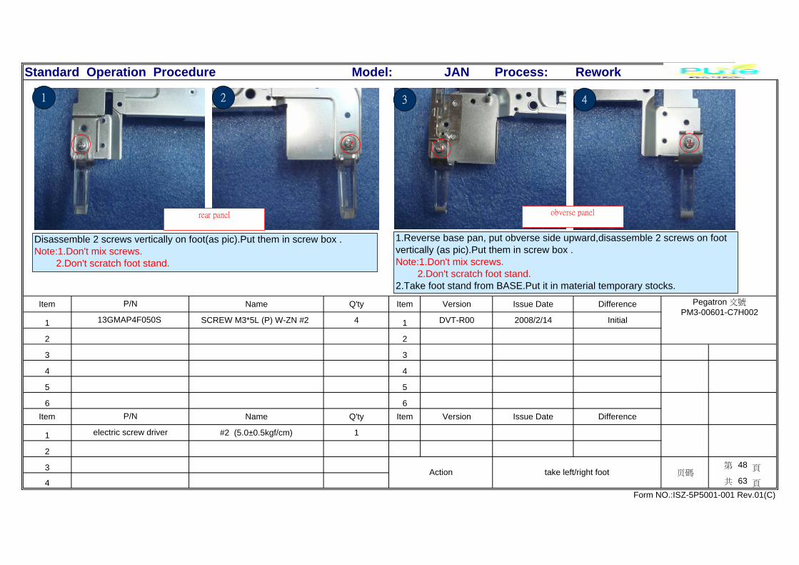
1 SCREW M3*5L (P) W-ZN #2 4 1 DVT-R00 2008/2/14 Initial
2 2
3 3
4 4
5 5
6 6Item Name Q'ty Item Version Issue Date Difference
1 #2 (5.0±0.5kgf/cm) 1
2
3 第 48 頁
4 共 63 頁
Form NO.:ISZ-5P5001-001 Rev.01(C)
Action take left/right foot 页碼
electric screw driver
P/N
Model:
P/N Pegatron 文號PM3-00601-C7H002
13GMAP4F050S
1.Reverse base pan, put obverse side upward,disassemble 2 screws on footvertically (as pic).Put them in screw box .Note:1.Don't mix screws. 2.Don't scratch foot stand.2.Take foot stand from BASE.Put it in material temporary stocks.
rear panel obverse panel
3 41 2
11 22
Disassemble 2 screws vertically on foot(as pic).Put them in screw box .Note:1.Don't mix screws. 2.Don't scratch foot stand.

Standard Operation Procedure JAN Process: Rework
Item Name Q'ty Item Version Issue Date Difference
1 JAN_BASE_PAN_ 1 1 DVT-R00 2008/2/14 Initial
2 2
3 3
4 4
5 5
6 6Item Name Q'ty Item Version Issue Date Difference
1
2
3 第 49 頁
4 共 63 頁
Form NO.:ISZ-5P5001-001 Rev.01(C)
Action check BASE PAN 页碼
P/N
Model:
P/N Pegatron 文號PM3-00601-C7H002
13GP157AM010-1H2
1.Take Base pan,check it no deformed ,no rusty,rivet OK. 2.Make sure 34screw boss existed&OK,(as yellowcircle).3.Make sure HDD&ODD hole existed.(as red circle).4.Make sure 3pcs sponge sticked well&in the rightposition.5.Put it in material temporary stockage.
1
Check 1pcs gasket on Base pan sticked OK.
2
Standard Operation Procedure JAN Process: Rework
Item Name Q'ty Item Version Issue Date Difference
1 1 DVT-R00 2008/2/14 Initial
2 2
3 3
4 4
5 5
6 6Item Name Q'ty Item Version Issue Date Difference
1
2
3 第 50 頁
4 共 63 頁
Form NO.:ISZ-5P5001-001 Rev.01(C)
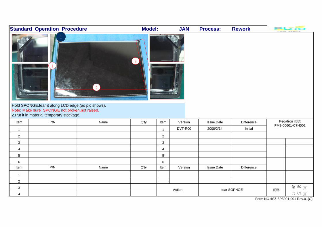
Action tear SOPNGE 页碼
P/N
Model:
P/N Pegatron 文號PM3-00601-C7H002
Hold SPONGE,tear it along LCD edge.(as pic shows).Note: Make sure SPONGE not broken,not raised.2.Put it in material temporary stockage.
1
13
2

Standard Operation Procedure JAN Process: Rework
Item Name Q'ty Item Version Issue Date Difference
1 LCD TFT 22' 1 1 DVT-R00 2008/2/14 Initial
2 2
3 3
4 4
5 5
6 6Item Name Q'ty Item Version Issue Date Difference
1
2
3 第 51 頁
4 共 63 頁
Form NO.:ISZ-5P5001-001 Rev.01(C)
Action check LCD 页碼
P/N
Model:
P/N Pegatron 文號PM3-00601-C7H002
18G242200001H2
1.Wipe surface dirty with clean cloth.2.Check LCD screen no scratch,nodirt,not broken.Note:1.Wipe PANEL.2.Spring liquor oncloth to wipe panel when it's hard toclean.
1.Reverse LCD,make LCD rear panel upward,confirm LCD no rusty,no deformed,check LCD TS controlcard cableOK,cable-routing is right(as pic).Make sure LCD M/B no foreign thing, PIN not slant,notbroken,inverter cable &connector OK.Note:Don't touch the yellow part in picture.
1 2 camera

Standard Operation Procedure JAN Process: Rework
Item Name Q'ty Item Version Issue Date Difference
1 SCREW M3*5L (P) W-ZN #2 5 1 DVT-R00 2008/2/14 Initial
2 2
3 3
4 4
5 5
6 6Item Name Q'ty Item Version Issue Date Difference
1 #2 (5.0±0.5kgf/cm) 1
2
3 第 52 頁
4 共 63 頁
Form NO.:ISZ-5P5001-001 Rev.01(C)
Action disassemble right frame screw 页碼
electric screw driver
P/N
Model:
P/N Pegatron 文號PM3-00601-C7H002
13GMAP4F050S
21
Disassemble 5 screws on right sidecap(as pic).Put them in screw box .Note:Don't scratch plastic part.
2
3
5
4
1
Take right side cap from LCDframe.
Press botton twice ,check it has feeling,spring smoothly.
3
Standard Operation Procedure JAN Process: Rework
Item Name Q'ty Item Version Issue Date Difference
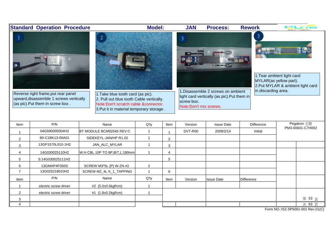
1 BT MODULE BCM92045 REV:C 1 1 DVT-R00 2008/2/14 Initial
2 SIDEKEYL-JAN/HP R1.02 1 2
3 JAN_ALC_MYLAR 1 3
4 W.H CBL 10P TO 8P,B/T,L:180mm 1 4
5 5
6 SCREW M3*5L (P) W-ZN #2 27 SCREW M2_4L K_1_TAPPING 1 6
Item Name Q'ty Item Version Issue Date Difference
1 #2 (5.0±0.5kgf/cm) 1
2 #1 (1.8±0.2kgf/cm) 1
3 第 53 頁
4 共 63 頁
13GMAP4F050S
Form NO.:ISZ-5P5001-001 Rev.01(C)
electric screw driver
13G025218010H2
P/N
electric screw driver
13GP1570L010-1H2
14G030025110H2
S:14G030025111H2
Model:
P/N Pegatron 文號PM3-00601-C7H002
04G590005004H2
80-C1BK13-00A01
21
1.Take blue tooth card (as pic).2. Pull out blue tooth Cable vertically.Note:Don't scratch cable &connector.3.Put it in material temporary storage .
Reverse right frame,put rear panelupward,disassemble 1 screws vertically(as pic).Put them in screw box .
1.Tear ambient light cardMYLAR(as yellow part).2.Put MYLAR & ambient light cardin discarding area.
3
1 2
3
1.Disassemble 2 screws on ambientlight card vertically (as pic).Put them inscrew box.Note:Don't mix screws.

Standard Operation Procedure JAN Process: Rework
Item Name Q'ty Item Version Issue Date Difference
1 JAN_SIDE_CAP_LF_ASM 1 1 DVT-R00 2008/2/14 Initial
2 10P TO 6P/5P,L:610mm 1 2
3 3
4 SCREW M3*5L (P) W-ZN #2 5 4
5 5
6 6Item Name Q'ty Item Version Issue Date Difference
1 #2 (5.0±0.5kgf/cm) 1
2
3 第 54 頁
4 共 63 頁
Form NO.:ISZ-5P5001-001 Rev.01(C)
Action disassemble left frame screw 页碼
electric screw driver
P/N
S:14G030036801H2
13GMAP4F050S
Model:
P/N Pegatron 文號PM3-00601-C7H002
13GP157AP030-1H2
14G030036800H2
1.Check right frame surface no dust,no scratch&hook isOK.Make sure 2 screw boss on ambient light botton card& 1screw boss on blue tooth card existed ,5 hook OK2.Put it in material temporary storage.
12
3
5
4
1
2
Disassemble 5 screws on left side capvertically (as pic).Put them in screw box .Note:Don't scratch plastic part.
3
Take left frame from LCD frame.

Standard Operation Procedure JAN Process: Rework
Item Name Q'ty Item Version Issue Date Difference
1 JAN_SIDEKEY_MYLAR 1 1 DVT-R00 2008/2/14 Initial
2 SIDEKEYR-JAN/HP R1.02 1 2
3 SCREW M3*5L (P) W-ZN #2 2 3
4 SIDEUP-JAN/HP 1 4
5 SCREW M3*5L (P) W-ZN #2 1 5
6 6Item Name Q'ty Item Version Issue Date Difference
1 #2 (5.0±0.5kgf/cm) 1
2
3 第 55 頁
4 共 63 頁
Form NO.:ISZ-5P5001-001 Rev.01(C)
Action disassmble Switch&VOLUME control card 页碼
electric screw driver
P/N
13GMAP4F050S
80-C1H010-00A01
13GMAP4F050S
Model:
P/N Pegatron 文號PM3-00601-C7H002
13GP1570L020-1H2
80-C1BK23-00A02
Pull out VOLUME 6 pin)+POWER Switch(5 pin)Cable vertically.Note:Don't damage cable &connector.
1
6 pin5 pin
1
Disassemble 1 screw on POWER Switch cardand 2 screw on volume card vertically (aspic).Put them in screw box .Note:Don't mix screw.Put two cards in material box.
2
23
1.Tear volume card MYLAR(asyellow part).2.Put MYLAR in discarding area.
3

Standard Operation Procedure JAN Process: Rework
Item Name Q'ty Item Version Issue Date Difference
1 JAN_SIDE_CAP_RT_ASM 1 1 DVT-R00 2008/2/14 Initial
2 2
3 3
4 4
5 5
6 6Item Name Q'ty Item Version Issue Date Difference
1
2
3 第 56 頁
4 共 63 頁
Form NO.:ISZ-5P5001-001 Rev.01(C)
Action check left frame 页碼
P/N
Model:
P/N Pegatron 文號PM3-00601-C7H002
13GP157AP020-1H2
Check left frame surface no dust ,no scratch.Make sure 2 screw boss.on .VOLUME Control card &1screw boss on Power switch card existedOK&Put it in material temporary storage
1
Standard Operation Procedure JAN Process: Rework
Item Name Q'ty Item Version Issue Date Difference
1 1 DVT-R00 2008/2/14 Initial
2 2
3 3
4 4
5 5
6 6Item Name Q'ty Item Version Issue Date Difference
1 #2 (5.0±0.5kgf/cm) 1
2
3 第 57 頁
4 共 63 頁
Form NO.:ISZ-5P5001-001 Rev.01(C)
Action disassemble bottom frame 页碼
electric screw driver
P/N
Model:
P/N Pegatron 文號PM3-00601-C7H002
1 23 4
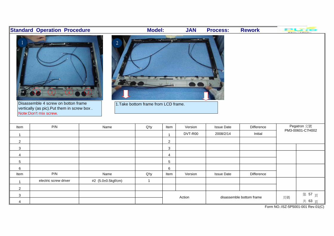
1.Take bottom frame from LCD frame.
21
Disassemble 4 screw on botton framevertically (as pic).Put them in screw box .Note:Don't mix screw.

Standard Operation Procedure JAN Process: Rework
Item Name Q'ty Item Version Issue Date Difference
1 WEBCAM_BRKT 1 1 DVT-R00 2008/2/14 Initial
2 SCREW M3*5L (P) W-ZN #2 2 2
3 8P TO 4P/5P WEB,L:680mm 1 3
4 4
5 5
6 6Item Name Q'ty Item Version Issue Date Difference
1 #2 (5.0±0.5kgf/cm) 1
2
3 第 58 頁
4 共 63 頁
Form NO.:ISZ-5P5001-001 Rev.01(C)
Action pull out camera cable 页碼
electric screw driver
P/N
14G030037100H2
S:14G030037101H2
Model:
P/N Pegatron 文號PM3-00601-C7H002
13GP1570M160-1H2
13GMAP4F050S
1
12
Disassemble 2 screw on camera vertically (aspic).Put them in screw box .Note:Don't mix screw.
1.Take camera module from unit.2.Tear camera tinfoil,put it in discardingarea.
2
Pull out camera cable from CONNECTOR.Note:Don't scratch cable&connector.2.Put them in material temporary storage.
3

Standard Operation Procedure JAN Process: Rework
Item Name Q'ty Item Version Issue Date Difference
1 AMBIENT LIGHT MODULE RGB 1 1 DVT-R00 2008/2/14 Initial
2 JAN_ACOUSTIC_SEAL 2 2
3 WEBCAM_LENS(GLASS ) 1 3
4 WEBCAM_gasket 1 4
5 5
6 6Item Name Q'ty Item Version Issue Date Difference
1
2
3 第 59 頁
4 共 63 頁
Form NO.:ISZ-5P5001-001 Rev.01(C)
Action IC dust proof&camera glass&cushion& ambie 页碼
P/N
13GP1570T070-1H2
13GP1570T080-1H2
Model:
P/N Pegatron 文號PM3-00601-C7H002
04G680001500H2
13GP1570T090-1H2
Take 2 pcs MIC dust-proof&1PCS cameraprotective glass&1PCS camera cushion(aspic).Note:Don't scratch camera glass.2.Put them in material temporary storage.
MIC dust
proofMIC dust
proof
camera protective glass(down)&camera cushion(up)
1 3
Pull out ambient light cableNote:Don't scratch cable.Put them in material temporarystorage.
Take ambient light module frombottom frame(as pic)Note: Don't make hook&ambientlight broken.
2

Standard Operation Procedure JAN Process: Rework
Item Name Q'ty Item Version Issue Date Difference
1 JAN_CHIN 1 1 DVT-R00 2008/2/14 Initial
2 8P TO 2IR/LED,L:290mm 1 2
3 3
4 JAN_IR_HOLDER 1 4
5 JAN_LED_HOLDER 1 5
6 6Item Name Q'ty Item Version Issue Date Difference
1
2
3 第 60 頁
4 共 63 頁
Form NO.:ISZ-5P5001-001 Rev.01(C)
Action disassemble IR module(1) 页碼
P/N
S:14G030036901H2
13GP1570P260-1H2
13GP1570T030-1H2
Model:
P/N Pegatron 文號PM3-00601-C7H002
13GP157AP050-1H2
14G030036900H2
1.Hold IR Receiver module 1&2hook push IR Receiver upwardcompletely.2.Put bottom frame in materialtemporary storage
1
1 32
Reverse IR plastic module,face to itsrear panel.Pull out IR light (as pic).Note: Don't damage cable& light. 1.Check light cover no broken,no deformed &2 hook existed.
2.Put it in material temporary storage.
Push IR plastic module(as pic).
assemble
crossing
3
2

Standard Operation Procedure JAN Process: Rework
Item Name Q'ty Item Version Issue Date Difference
1 1 DVT-R00 2008/2/14 Initial
2 2
3 3
4 4
5 5
6 6Item Name Q'ty Item Version Issue Date Difference
1
2
3 第 61 頁
4 共 63 頁
Form NO.:ISZ-5P5001-001 Rev.01(C)
Action disassemble IR module(2) 页碼
P/N
Model:
P/N Pegatron 文號PM3-00601-C7H002
2 3
2
1
21
Take IR receiver from IR plastic module(aspic)Note: Don't damage cable
Face to IR plastic module(as pic).Note: Don't damage cable&light.Put IR receiver&IR CABLE inmaterial temporary storage.

Standard Operation Procedure JAN Process: Rework
Item Name Q'ty Item Version Issue Date Difference
1 HOTS-JAN/HP R1.02 1 1 DVT-R00 2008/2/14 Initial
2 JAN_HOTKEY_BRKT 1 2
3 3
4 4
5 5
6 6Item Name Q'ty Item Version Issue Date Difference
1 #1 (1.0±0.2kgf/cm) 1
2
3 第 62 頁
4 共 63 頁
Form NO.:ISZ-5P5001-001 Rev.01(C)
Action disassembleLED cable 页碼
electric screw driver
P/N
Model:
P/N Pegatron 文號PM3-00601-C7H002
80-C1BK03-00A01
13GP1570M330-1H2
Pull out LED from holder .Note:Don'tmake LED holder hook&cable broken.Put it in material temporary storage.
21 3
Disassemble 1 screw on Hot Startvertically(as pic),put screw in screw box.Note: Don't mix screw.
Take Hot Start BRKT(as yellowpart),put it in material temporarystorage.
Standard Operation Procedure JAN Process: Rework
Item Name Q'ty Item Version Issue Date Difference
1 JAN_FRONT_BEZEL_ASM 1 1 DVT-R00 2008/2/14 Initial
2 WH CBL 4P TO 4P SMART/C,L270m 1 2
3 3
4 4
5 5
6 6Item Name Q'ty Item Version Issue Date Difference
1
2
3 第 63 頁
4 共 63 頁
Form NO.:ISZ-5P5001-001 Rev.01(C)
Action sassemble Hot Start module&LCD bottom fram 页碼
P/N
S:14G030036601H2
Model:
P/N Pegatron 文號PM3-00601-C7H002
13GP157AP010-1H2
14G030036600H2
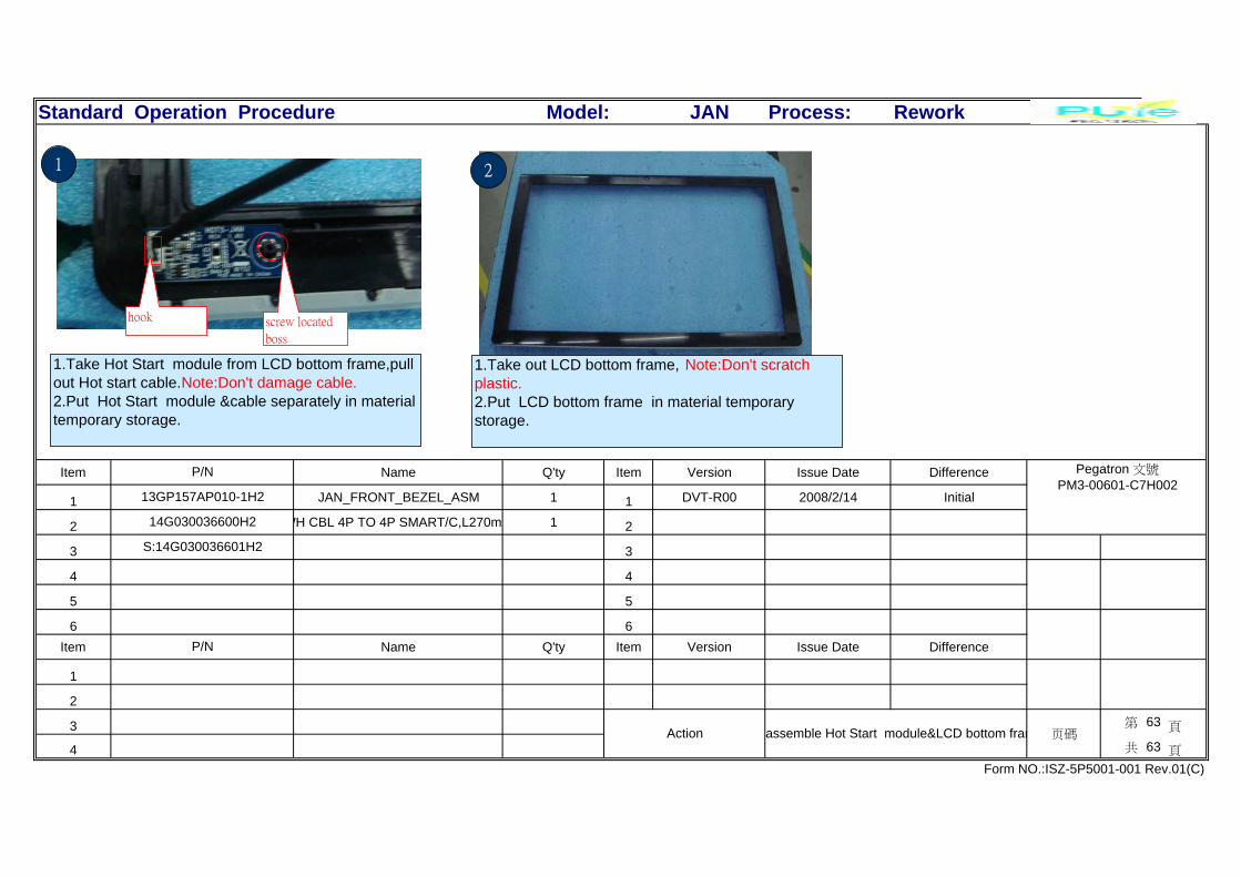
1.Take Hot Start module from LCD bottom frame,pullout Hot start cable.Note:Don't damage cable.2.Put Hot Start module &cable separately in materialtemporary storage.
1
screw located
boss
hook
2
1.Take out LCD bottom frame, Note:Don't scratchplastic.2.Put LCD bottom frame in material temporarystorage.