Embed Size (px)
Citation preview
Technical white paper
HP 2920 Switch Series stacking
Table of contents Introduction .................................................................................................................................................................................... 2
Achieve new levels of network performance and resiliency ............................................................................................... 2
Using HP switch virtualization technologies ........................................................................................................................... 3
Freedom to choose ....................................................................................................................................................................... 4
Stacking topologies ...................................................................................................................................................................... 5
Ring topologies .......................................................................................................................................................................... 6
Chain topologies ........................................................................................................................................................................ 7
Stacking terms ........................................................................................................................................................................... 7
Creating a stack ......................................................................................................................................................................... 9
Adding a switch to a stack ..................................................................................................................................................... 13
Removing a switch from a stack .......................................................................................................................................... 13
Renumbering stack members .............................................................................................................................................. 14
Restoring the operation of a stack ...................................................................................................................................... 16
Stack software update ........................................................................................................................................................... 17
Creating a stack from standalone switches ...................................................................................................................... 17
Stacking notes ......................................................................................................................................................................... 17
Technical white paper | HP 2920 Switch Series stacking
Introduction
This white paper describes how the HP switch virtualization technologies can deliver high-performance and highly available switching while simplifying management and lowering costs. It is aimed at CTOs, CIOs, IT managers, or business managers, who are interested in making their enterprise network more flexible.
HP switch virtualization technologies offer three benefits:
• Simplicity by aggregating the management of multiple physical switches under the management of one.
• Resiliency by maintaining redundant management and offering simple and industry standard link aggregation.
• Capacity can be increased as needs grow by adding members to an existing stack.
Achieve new levels of network performance and resiliency
HP FlexNetwork architecture leverages a set of switch virtualization technologies that allow enterprises to dramatically simplify the design and operations of their data center, campus, and branch office Ethernet networks. HP switch virtualization technologies essentially “flattens” data center and campus networks, helping eliminate the need for a dedicated aggregation layer. It provides direct, higher capacity connections between users and network resources. It allows enterprises to overcome the limitations of legacy design and inefficient protocols by delivering new levels of network performance and resiliency.
HP switch virtualization technologies extend the performance and scalability benefits of modular, chassis-based switches to both modular and stackable switches. No longer do businesses need to compromise enterprise capabilities for the convenience and cost of a stackable switch.
HP switch virtualization technologies including HP Intelligent Resilient Framework (IRF), HP Mesh Technology, and HP 2920 stacking Technology are included in a variety of HP data center and campus and branch office switches. The operation of the three network virtualization technologies are similar.
With HP switch virtualization technologies, one switch within a domain or stack operates as the primary switch. The associated switches provide Layer 2 and Layer 3 functionality for directly connected users. Optimal routes are calculated based on the entire logical domain, rather than the individual switches that the domain represents.
All switches in a stack or domain are managed as a single entity using one IP address by the managing logical switch. If the primary switch fails, a new switch is instantly selected, which prevents service interruption, and helps ensure application and network continuity.
HP switch virtualization technologies:
• Simplify the network design: Simplifying the data center or campus network from 3 tiers to 2 tiers with HP switch virtualization technologies has many benefits such as higher performance with less complexity. It helps eliminate network layers, reduces the latency that is inherent in multitier networks, and enables better user experience, whether it is for voice, video, or other highly sensitive applications. With fewer network devices to purchase and manage, both capital and operational expenses are lower.
• Enable higher performance: HP switch virtualization technologies deliver greater efficiency and performance. Unlike with STP, which can consume half of the network bandwidth, HP switch virtualization technologies gives all the bandwidth you are paying for. HP switch virtualization technologies keep all the links active and enable efficient, high-bandwidth connectivity throughout the switching plane. This is true even for multicast data, which is often a major consumer of network bandwidth.
• Deliver greater resiliency: HP switch virtualization technologies usage decreases network downtime by providing higher levels of availability and resiliency. HP switch virtualization technologies deliver faster failover than STP and its relatives, which means higher availability. For example, when a link or switch failure occurs, HP IRF can recover rapidly and reconverge the network in less than 50 ms. While, HP 3800 Switch Series with Mesh Technology reconverges the network with less than 5 ms of latency.
• Ease of management: HP switch virtualization technologies create a single logical switch by grouping several physical switches into a stack or domain with a single IP address so that there is no need to connect, configure, and manage switches individually. Multiple active switches can be controlled via a single management interface, which vastly simplifies network configuration and operations.
• Add capacity as you grow: Enterprises can add capacity on a “pay-as-you-grow” basis by adding switches to the stack. Businesses can achieve massively scalable performance that’s necessary for today’s intensive applications, whether it is virtualized workload mobility in the data center or video on-demand in the branch. Initial acquisition costs are lower as you can buy only the capacity you need and there’s no compromise on scalability as needs grow.
2
Technical white paper | HP 2920 Switch Series stacking
Using HP switch virtualization technologies
HP switch virtualization technologies are used across the HP FlexFabric, HP FlexCampus, and HP FlexBranch architectures. HP has developed two technologies that aggregate multiple switches into a larger switch. HP IRF utilizes standard 10 or 40 Gig interfaces, that can be designated as IRF links, to interconnect the switches and HP Meshed stacking and 2920 stacking use dedicated stacking modules and interfaces to accomplish the same objective.
HP IRF technology is leveraged across the HP switch portfolio, including for the HP 125xx, 105xx, 75xx, 58xx, 55xx, 5120, and 3600v2 Switch Series. Also, HP IRF is designed for the unforgiving data center and campus environments. Up to nine HP switches of the same family can be combined into a single domain to create an ultra-resilient virtual switching fabric. The fabric may comprise hundreds or even thousands of 1GbE or 10GbE switch ports.
You can utilize multiple 10 or 40GbE between switches to further boost performance. This allows scalable on-demand capacity to support critical business applications.
HP IRF also delivers a network-based in-service software upgrade (ISSU) capability that allows individual HP IRF-enabled switches to be taken offline for servicing or software upgrades without affecting traffic going to other switches in the HP IRF domain.
HP Meshed stacking and 2920 stacking deliver a high-performance, scalable network to support media-intensive applications for campus and branch offices. The HP 3800 Switch Series provides the industry’s highest level of resiliency in a 1U stackable switch, and the HP 2920 Switch Series provides fixed-port, basic Layer 3 switching with modular 10G capabilities and each of these switches offer virtualization solutions.
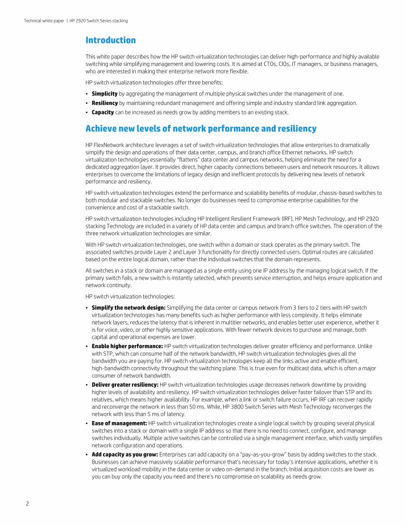
Up to ten HP 3800 Switch Series can be configured in a ring topology. In this configuration, a link or switch failure creates a chain topology, which enables continued operations. Also, up to five HP 3800 switches can be fully meshed using HP Mesh technology. With each switch directly connected in a mesh configuration, a link or switch failure results in minimal to no impact on the performance of the remaining network.
Configuration of the HP 3800 is truly plug and play. A single management interface is used to configure up to ten switches in a stack. Software updates are simple too. You only need to update one switch and the others are updated automatically. When the time comes to add capacity, additional switches can be added to the stack.
The HP 3800 Switch Series has dual-redundant power supplies so that a power failure does not impact the network. The switch can be serviced in the field, with hot-swappable power supplies and a hot-swappable fan tray. These hardware innovations, in conjunction with a robust Layer 3 feature set, including BGP, OSPF, Virtual Router Redundancy Protocol VRRP, and more, makes the HP 3800 Switch Series one of the most agile and resilient stackable network infrastructure solutions available.
The HP 3800 Switch Series provides comprehensive protection against threats focused on the critical path of the network. It supports IEEE 802.1x for network access control. It also supports virus throttling for attack mitigation and traffic mirroring. The management interface is also encrypted and sensitive configuration information is protected.
3
Technical white paper | HP 2920 Switch Series stacking
Figure 1. HP 3800 stacking topologies
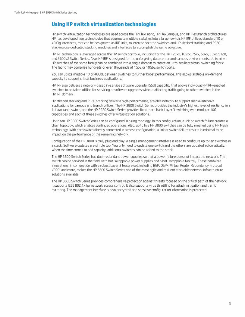
The HP 2920 Switch Series can stack up to four switches in a chain or ring topology. In the ring configuration, a link or switch failure creates a chain topology, which enables continued operations. Like the HP 3800 Switch Series, configuration of the HP 2920 is also plug and play. A single management interface is used to configure up to four switches in a stack. Software updates are simple. If one switch is updated, others are updated automatically and to add capacity, additional switches can be added to the stack.
Figure 2. HP 2920 stacking—ring topology
Figure 3. HP 2920 stacking—chain topology
The HP 2920 Switch Series has a removable power supply in case the need for additional PoE power is required or if switch needs to be serviced in the field. Also, this switch series provides the flexibility to add 10G uplinks through optional modules that slot into the back of the box. These hardware innovations, in conjunction with a basic Layer 3 feature set, including static and RIP routing makes the HP 2920 Switch Series one of the most flexible, stackable network infrastructure solutions available.
Both the HP 3800 and HP 2920 Switch Series are ideal for organizations that place a priority on green IT, as the switches support the IEEE 802.3az Energy Efficiency Ethernet for reduced power consumption. These switches also support 10GbE over standard copper cabling as well as IPv6. In addition, both families support OpenFlow (HP 2920 Switch Series support early 2013) and are part of the HP Software-defined Networking solution.
Freedom to choose
With HP, enterprises have the freedom to choose proven networking technologies for their data centers, campus, and branch offices. HP switch virtualization technologies, a key element in the FlexNetwork architecture, allow enterprises to simplify and scale their networks while helping eliminate time-worn designs and protocols. With HP FlexNetwork, enterprises can free themselves from vendor lock-in and build a high-performance, scalable, and affordable network that supports how businesses and people work today.
Chain configuration
…
10
9
8
1
…
10
9
8
1
Ring configuration
1
21
23
14
33
1
34
25
Mesh configurations
4
Technical white paper | HP 2920 Switch Series stacking
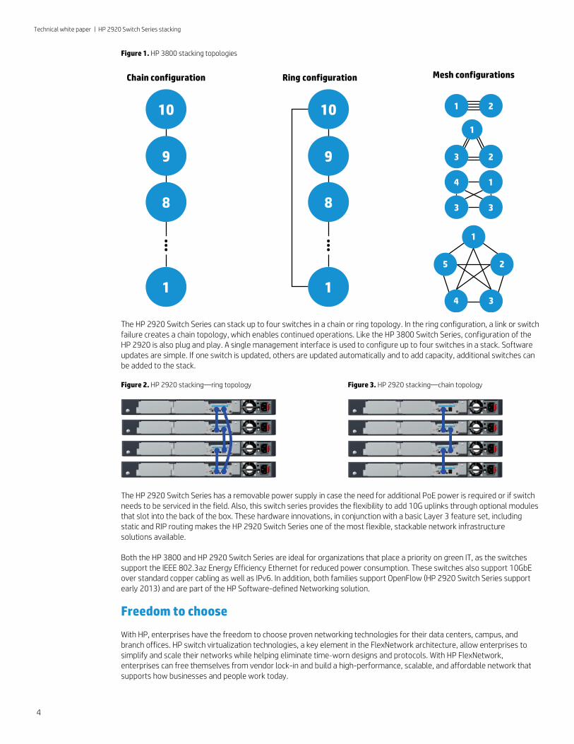
Table 1. HP Networking Stacking Technologies
HP Intelligent Resilient Framework (HP IRF)
Meshed stacking on HP 3800 Series
HP 2920 Switch Series stacking
Max switches in a stack 9 10 4
Topologies Ring, chain Mesh, ring, chain Ring, chain
Cable lengths Up to 70 km 0.5, 1, and 3 m 0.5, 1, and 3 m
Throughput
10 Gbps/link
Up to 320 Gbps
(full-duplex)
42 Gbps/link
Up to 168 Gbps
(full-duplex)
20 Gbps/link
Up to 40 Gbps
(full-duplex)
Configurable/Dedicated Configurable Dedicated Dedicated
Stacking topologies
The HP 2920 Switch Series provide a stacking solution where all switches in a stack acting as “One Switch”. The stacking links between switches carry both data and stack management communications. Two different stacking topologies, ring and chain, are supported by the HP 2920 Switch Series.
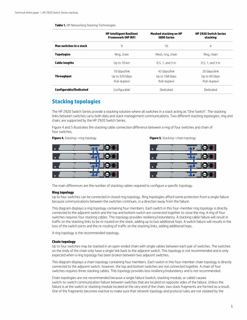
Figure 4 and 5 illustrates the stacking cable connection difference between a ring of four switches and chain of four switches.
Figure 4. Stacking—ring topology
Figure 5. Stacking—chain topology
The main differences are the number of stacking cables required to configure a specific topology.
Ring topology Up to four switches can be connected in closed ring topology. Ring topologies afford some protection from a single failure because communications between the switches continues, in a direction away from the failure.
This diagram displays a ring topology containing four members. Each switch in this four-member ring topology is directly connected to the adjacent switch and the top and bottom switch are connected together to close the ring. A ring of four switches requires four stacking cables. This topology provides resiliency/redundancy. A stacking cable failure will result in traffic on the stacking links to be re-routed on the stack, adding up to two additional hops. A switch failure will results in the loss of the switch ports and the re-routing of traffic on the stacking links, adding additional hops.
A ring topology is the recommended topology.
Chain topology Up to four switches may be stacked in an open-ended chain with single cables between each pair of switches. The switches on the ends of the chain only have a single link back to the adjacent switch. This topology is not recommended and is only expected when a ring topology has been broken between two adjacent switches.
This diagram displays a chain topology containing four members. Each switch in this four-member chain topology is directly connected to the adjacent switch, however, the top and bottom switches are not connected together. A chain of four switches requires three stacking cables. This topology provides less resiliency/redundancy and is not recommended.
Chain topologies are not recommended because a single failure (switch, stacking module, or cable) causes switch-to-switch communication failure between switches that are located on opposite sides of the failure. Unless the failure is at the switch or stacking module located at the very end of the chain, two stack fragments are formed as a result. One of the fragments becomes inactive to make sure that network topology and protocol rules are not violated by the
5
Technical white paper | HP 2920 Switch Series stacking
creation of two virtual switches. For the inactive fragment, the switches remain powered on and create a separate stack, but all of network ports on the switches in the inactive fragment become disabled and do not pass network traffic.
Connect only HP 2920 Switch Series in a switch stack. You cannot stack the HP 2920 Switch Series with other HP Networking switches like the HP 3800 Switch Series, HP 5120 Switch Series, or HP 5500 Switch Series to name a few.
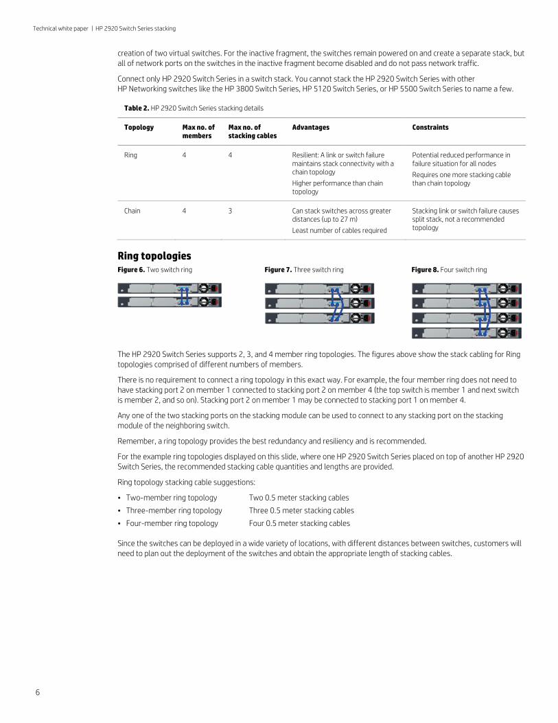
Table 2. HP 2920 Switch Series stacking details
Topology Max no. of members
Max no. of stacking cables
Advantages Constraints
Ring 4 4 Resilient: A link or switch failure maintains stack connectivity with a chain topology
Higher performance than chain topology
Potential reduced performance in failure situation for all nodes
Requires one more stacking cable than chain topology
Chain 4 3 Can stack switches across greater distances (up to 27 m)
Least number of cables required
Stacking link or switch failure causes split stack, not a recommended topology
Ring topologies Figure 6. Two switch ring
Figure 7. Three switch ring
Figure 8. Four switch ring
The HP 2920 Switch Series supports 2, 3, and 4 member ring topologies. The figures above show the stack cabling for Ring topologies comprised of different numbers of members.
There is no requirement to connect a ring topology in this exact way. For example, the four member ring does not need to have stacking port 2 on member 1 connected to stacking port 2 on member 4 (the top switch is member 1 and next switch is member 2, and so on). Stacking port 2 on member 1 may be connected to stacking port 1 on member 4.
Any one of the two stacking ports on the stacking module can be used to connect to any stacking port on the stacking module of the neighboring switch.
Remember, a ring topology provides the best redundancy and resiliency and is recommended.
For the example ring topologies displayed on this slide, where one HP 2920 Switch Series placed on top of another HP 2920 Switch Series, the recommended stacking cable quantities and lengths are provided.
Ring topology stacking cable suggestions:
• Two-member ring topology Two 0.5 meter stacking cables
• Three-member ring topology Three 0.5 meter stacking cables
• Four-member ring topology Four 0.5 meter stacking cables
Since the switches can be deployed in a wide variety of locations, with different distances between switches, customers will need to plan out the deployment of the switches and obtain the appropriate length of stacking cables.
6
Technical white paper | HP 2920 Switch Series stacking
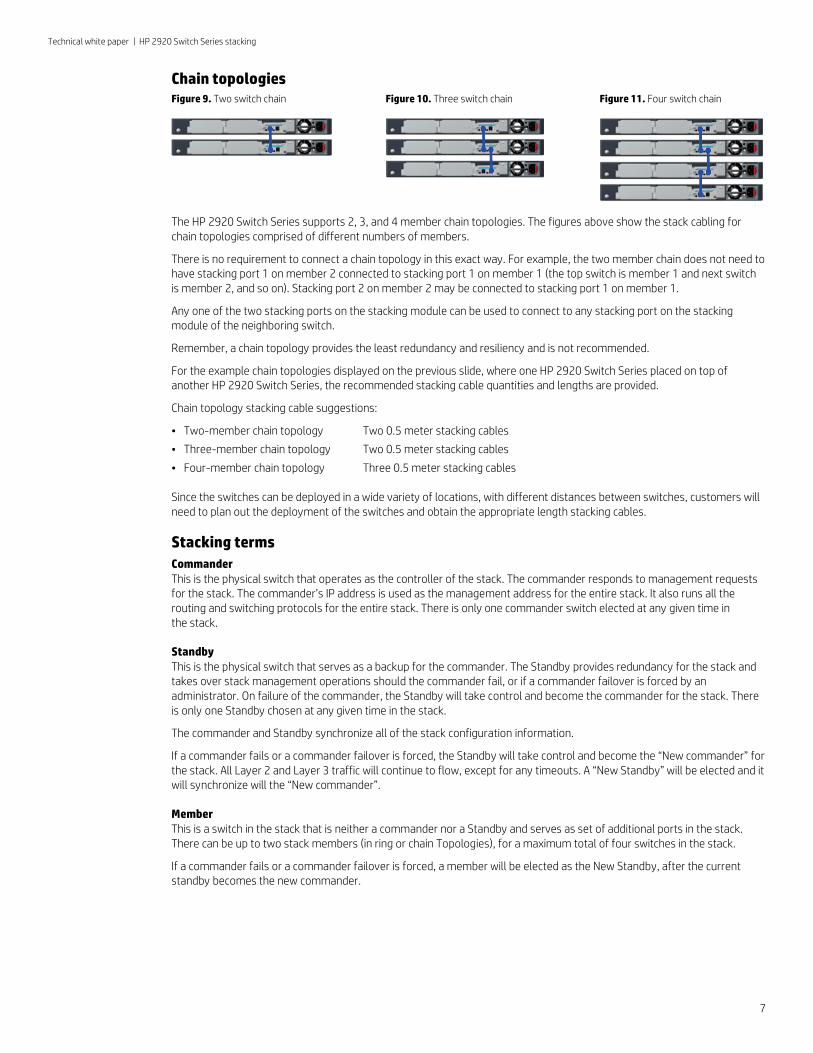
Chain topologies Figure 9. Two switch chain
Figure 10. Three switch chain
Figure 11. Four switch chain
The HP 2920 Switch Series supports 2, 3, and 4 member chain topologies. The figures above show the stack cabling for chain topologies comprised of different numbers of members.
There is no requirement to connect a chain topology in this exact way. For example, the two member chain does not need to have stacking port 1 on member 2 connected to stacking port 1 on member 1 (the top switch is member 1 and next switch is member 2, and so on). Stacking port 2 on member 2 may be connected to stacking port 1 on member 1.
Any one of the two stacking ports on the stacking module can be used to connect to any stacking port on the stacking module of the neighboring switch.
Remember, a chain topology provides the least redundancy and resiliency and is not recommended.
For the example chain topologies displayed on the previous slide, where one HP 2920 Switch Series placed on top of another HP 2920 Switch Series, the recommended stacking cable quantities and lengths are provided.
Chain topology stacking cable suggestions:
• Two-member chain topology Two 0.5 meter stacking cables
• Three-member chain topology Two 0.5 meter stacking cables
• Four-member chain topology Three 0.5 meter stacking cables
Since the switches can be deployed in a wide variety of locations, with different distances between switches, customers will need to plan out the deployment of the switches and obtain the appropriate length stacking cables.
Stacking terms Commander This is the physical switch that operates as the controller of the stack. The commander responds to management requests for the stack. The commander’s IP address is used as the management address for the entire stack. It also runs all the routing and switching protocols for the entire stack. There is only one commander switch elected at any given time in the stack.
Standby This is the physical switch that serves as a backup for the commander. The Standby provides redundancy for the stack and takes over stack management operations should the commander fail, or if a commander failover is forced by an administrator. On failure of the commander, the Standby will take control and become the commander for the stack. There is only one Standby chosen at any given time in the stack.
The commander and Standby synchronize all of the stack configuration information.
If a commander fails or a commander failover is forced, the Standby will take control and become the “New commander” for the stack. All Layer 2 and Layer 3 traffic will continue to flow, except for any timeouts. A “New Standby” will be elected and it will synchronize will the “New commander”.
Member This is a switch in the stack that is neither a commander nor a Standby and serves as set of additional ports in the stack. There can be up to two stack members (in ring or chain Topologies), for a maximum total of four switches in the stack.
If a commander fails or a commander failover is forced, a member will be elected as the New Standby, after the current standby becomes the new commander.
7
Technical white paper | HP 2920 Switch Series stacking
Traffic flow through a ring topology
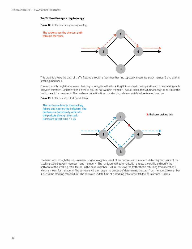
Figure 12. Traffic flow through a ring topology
This graphic shows the path of traffic flowing through a four-member ring topology, entering a stack member 2 and exiting stacking member 4.
The red path through the four-member ring topology is with all stacking links and switches operational. If the stacking cable between member 1 and member 4 were to fail, the hardware in member 1 would sense the failure and start to re-route the traffic meant for member 4. The hardware detection time of a stacking cable or switch failure is less than 1 µs.
Figure 13. Traffic flow after stacking link failure
The blue path through the four-member Ring topology is a result of the hardware in member 1 detecting the failure of the stacking cable between member 1 and member 4. The hardware will automatically re-route the traffic and notify the software of the stacking cable failure. In this case, member 2 will re-route all the traffic that is returning from member 1 which is meant for member 4. The software will then begin the process of determining the path from member 2 to member 4 due to the stacking cable failure. The software update time of a stacking cable or switch failure is around 100 ms.
1
42
3
The packets use the shortest path through the stack.
The hardware detects the stackingfailure and notifies the Software. Thehardware automatically redirectsthe packets through the stack. Hardware detect time < 1 µs
1
42
3
X: Broken stacking link
X
8
Technical white paper | HP 2920 Switch Series stacking
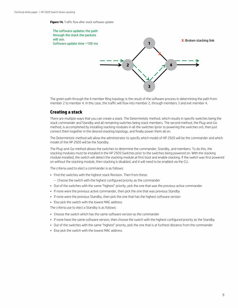
Figure 14. Traffic flow after stack software update
The green path through the 4 member Ring topology is the result of the software process in determining the path from member 2 to member 4. In this case, the traffic will flow into member 2, through members 3 and exit member 4.
Creating a stack There are multiple ways that you can create a stack. The Deterministic method, which results in specific switches being the stack commander and Standby and all remaining switches being stack members. The second method, the Plug-and-Go method, is accomplished by installing stacking modules in all the switches (prior to powering the switches on), then just connect them together in the desired stacking topology, and finally power them all on.
The Deterministic method will allow the administrator to specify which model of HP 2920 will be the commander and which model of the HP 2920 will be the Standby.
The Plug-and-Go method allows the switches to determine the commander, Standby, and members. To do this, the stacking modules must be installed in the HP 2920 Switches prior to the switches being powered on. With the stacking module installed, the switch will detect the stacking module at first boot and enable stacking. If the switch was first powered on without the stacking module, then stacking is disabled, and it will need to be enabled via the CLI.
The criteria used to elect a commander is as follows:
• Find the switches with the highest stack Revision. Then from these:
– Choose the switch with the highest configured priority as the commander
• Out of the switches with the same “highest” priority, pick the one that was the previous active commander
• If none were the previous active commander, then pick the one that was previous Standby
• If none were the previous Standby, then pick the one that has the highest software version
• Else pick the switch with the lowest MAC address
The criteria use to elect a Standby is as follows:
• Choose the switch which has the same software version as the commander
• If none have the same software version, then choose the switch with the highest configured priority as the Standby
• Out of the switches with the same “highest” priority, pick the one that is at furthest distance from the commander
• Else pick the switch with the lowest MAC address
The software updates the path through the stack the packets will use.Software update time >100 ms 1
42
3
X: Broken stacking link
X
9

Technical white paper | HP 2920 Switch Series stacking
Steps to configure a stack with the Deterministic method 1. Adding the stacking module after the switch has been powered on for the first time, will require stacking to be enabled
via the CLI. This will allow for the Deterministic method of configuring a stack of HP 2920 Switch Series. Figure 15. Install stacking module after initial switch power on/off
2. Make sure that stacking is enabled for the switch. You can determine this by issuing the command “show stacking” from the switch CLI. If stacking is disabled, then go to the Config context in the CLI and issue the command: HP Switch(config)# stacking enable. This command causes the switch to reboot.
Figure 16. Enable stacking
3. When the switch is fully booted, issue the “show stacking” command again and you will notice that the switch now has the status of commander, that it has a member ID of 1 (one), and the default priority of 128.
Figure 17. Stack commander
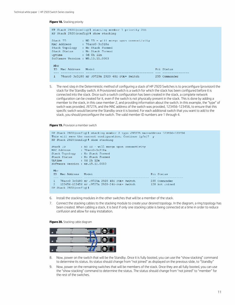
4. To retain its function as commander through stack boots and other situations, you can increase the priority of this switch. The highest priority switch will be commander when all the switches are booted simultaneously. Default priority is 128; priority range is 1 to 255. To increase the switches stacking priority, from the Config context, issue the command: HP Switch(config)# stacking member 1 priority 255.
10
Technical white paper | HP 2920 Switch Series stacking
Figure 18. Stacking priority
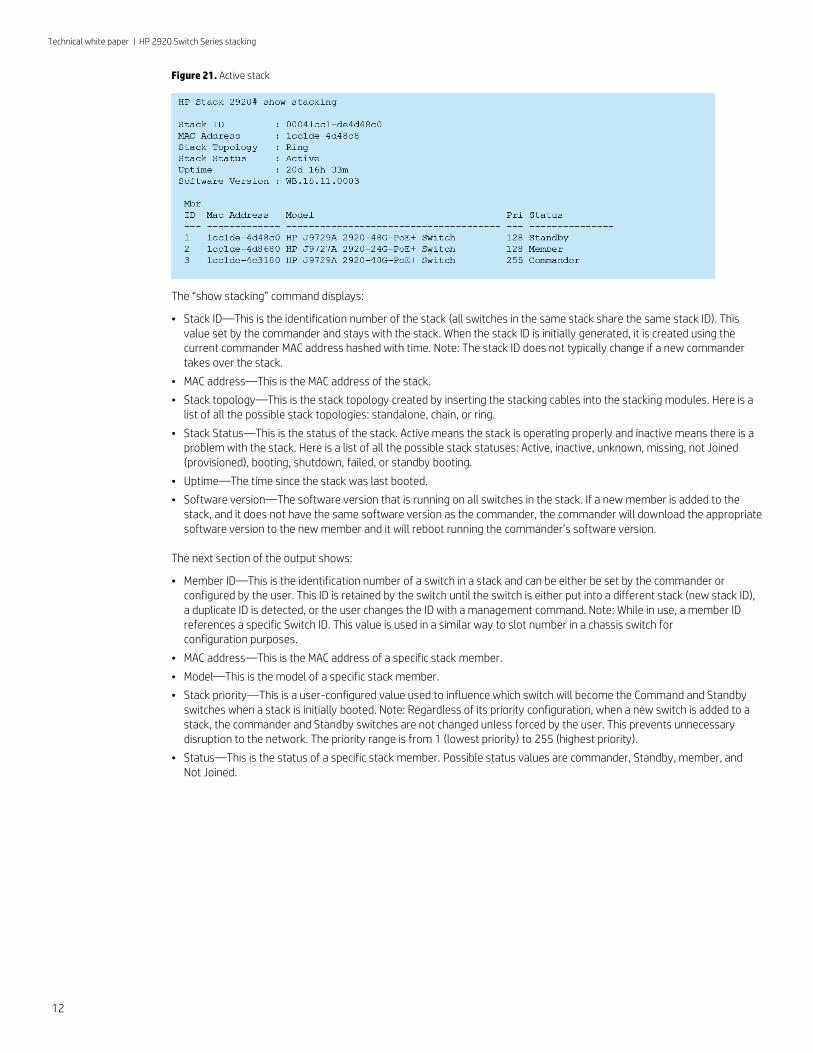
5. The next step in the Deterministic method of configuring a stack of HP 2920 Switches is to preconfigure (provision) the stack for the Standby switch. A Provisioned switch is a switch for which the stack has been configured before it is connected into the stack. Once such a switch configuration has been created in the stack, a complete network configuration can be created for it, even if the switch is not physically present in the stack. This is done by adding a member to the stack, in this case member 2, and providing information about the switch. In this example, the “type” of switch was provided, J9727A, and the MAC address of the switch was provided, 123456-123456, to ensure that this specific switch would become the Standby once it is booted. For each additional switch that you want to add to the stack, you should preconfigure the switch. The valid member ID numbers are 1 through 4.
Figure 19. Provision a member switch
6. Install the stacking modules in the other switches that will be a member of the stack.
7. Connect the stacking cables to the stacking module to create your desired topology. In the diagram, a ring topology has been created. When cabling a stack, it is best if only one stacking cable is being connected at a time in order to reduce confusion and allow for easy installation.
Figure 20. Stacking cable diagram
8. Now, power on the switch that will be the Standby. Once it is fully booted, you can use the “show stacking” command to determine its status. Its status should change from “not joined” as displayed on the previous slide, to “Standby”
9. Now, power on the remaining switches that will be members of the stack. Once they are all fully booted, you can use the “show stacking” command to determine the status. The status should change from “not joined” to “member” for the rest of the switches.
11
Technical white paper | HP 2920 Switch Series stacking
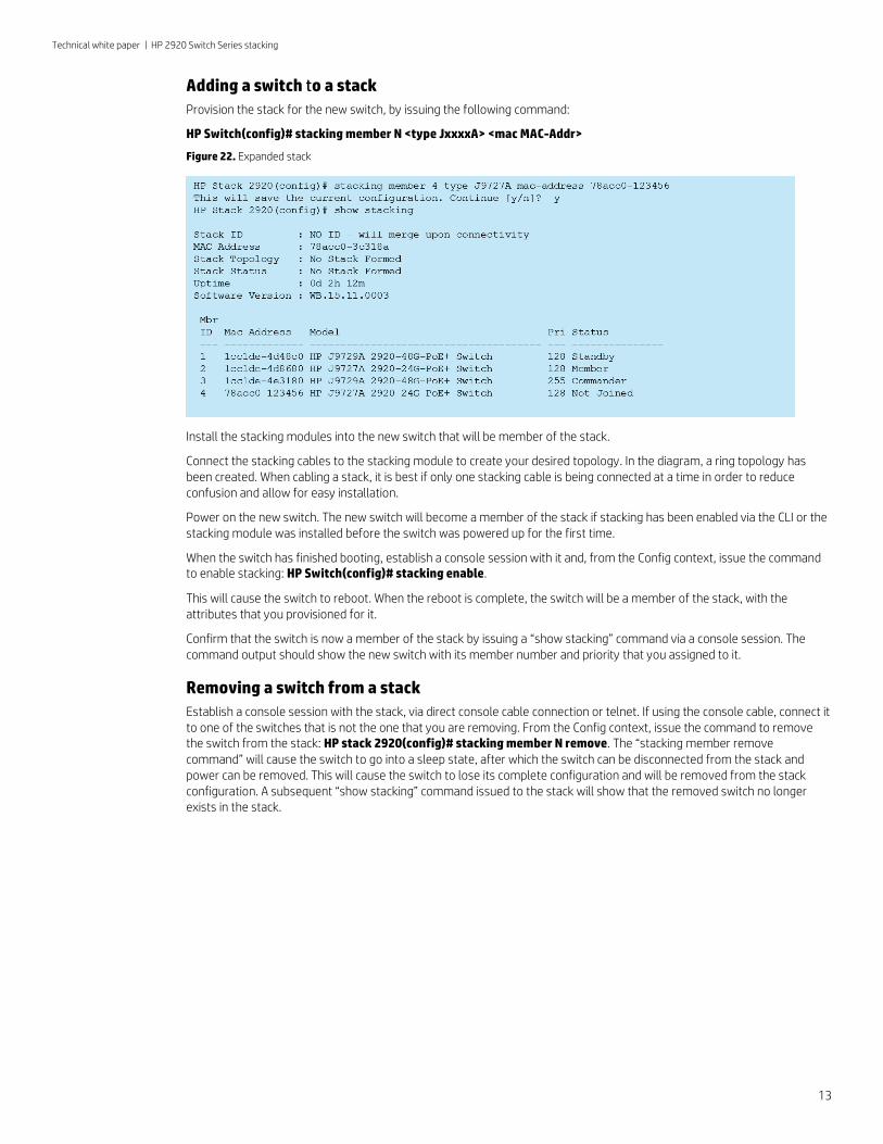
Figure 21. Active stack
The “show stacking” command displays:
• Stack ID—This is the identification number of the stack (all switches in the same stack share the same stack ID). This value set by the commander and stays with the stack. When the stack ID is initially generated, it is created using the current commander MAC address hashed with time. Note: The stack ID does not typically change if a new commander takes over the stack.
• MAC address—This is the MAC address of the stack.
• Stack topology—This is the stack topology created by inserting the stacking cables into the stacking modules. Here is a list of all the possible stack topologies: standalone, chain, or ring.
• Stack Status—This is the status of the stack. Active means the stack is operating properly and inactive means there is a problem with the stack. Here is a list of all the possible stack statuses: Active, inactive, unknown, missing, not Joined (provisioned), booting, shutdown, failed, or standby booting.
• Uptime—The time since the stack was last booted.
• Software version—The software version that is running on all switches in the stack. If a new member is added to the stack, and it does not have the same software version as the commander, the commander will download the appropriate software version to the new member and it will reboot running the commander’s software version.
The next section of the output shows:
• Member ID—This is the identification number of a switch in a stack and can be either be set by the commander or configured by the user. This ID is retained by the switch until the switch is either put into a different stack (new stack ID), a duplicate ID is detected, or the user changes the ID with a management command. Note: While in use, a member ID references a specific Switch ID. This value is used in a similar way to slot number in a chassis switch for configuration purposes.
• MAC address—This is the MAC address of a specific stack member.
• Model—This is the model of a specific stack member.
• Stack priority—This is a user-configured value used to influence which switch will become the Command and Standby switches when a stack is initially booted. Note: Regardless of its priority configuration, when a new switch is added to a stack, the commander and Standby switches are not changed unless forced by the user. This prevents unnecessary disruption to the network. The priority range is from 1 (lowest priority) to 255 (highest priority).
• Status—This is the status of a specific stack member. Possible status values are commander, Standby, member, and Not Joined.
12
Technical white paper | HP 2920 Switch Series stacking
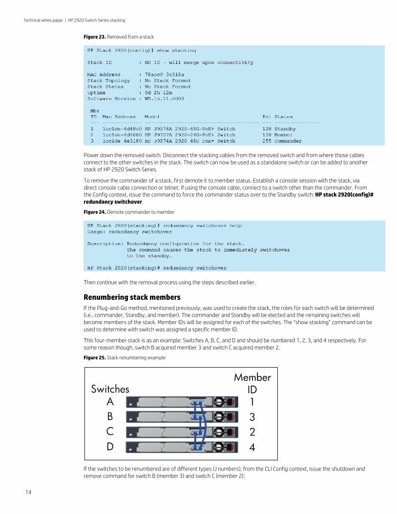
Adding a switch to a stack Provision the stack for the new switch, by issuing the following command:
HP Switch(config)# stacking member N <type JxxxxA> <mac MAC-Addr>
Figure 22. Expanded stack
Install the stacking modules into the new switch that will be member of the stack.
Connect the stacking cables to the stacking module to create your desired topology. In the diagram, a ring topology has been created. When cabling a stack, it is best if only one stacking cable is being connected at a time in order to reduce confusion and allow for easy installation.
Power on the new switch. The new switch will become a member of the stack if stacking has been enabled via the CLI or the stacking module was installed before the switch was powered up for the first time.
When the switch has finished booting, establish a console session with it and, from the Config context, issue the command to enable stacking: HP Switch(config)# stacking enable.
This will cause the switch to reboot. When the reboot is complete, the switch will be a member of the stack, with the attributes that you provisioned for it.
Confirm that the switch is now a member of the stack by issuing a “show stacking” command via a console session. The command output should show the new switch with its member number and priority that you assigned to it.
Removing a switch from a stack Establish a console session with the stack, via direct console cable connection or telnet. If using the console cable, connect it to one of the switches that is not the one that you are removing. From the Config context, issue the command to remove the switch from the stack: HP stack 2920(config)# stacking member N remove. The “stacking member remove command” will cause the switch to go into a sleep state, after which the switch can be disconnected from the stack and power can be removed. This will cause the switch to lose its complete configuration and will be removed from the stack configuration. A subsequent “show stacking” command issued to the stack will show that the removed switch no longer exists in the stack.
13
Technical white paper | HP 2920 Switch Series stacking
Figure 23. Removed from a stack
Power down the removed switch. Disconnect the stacking cables from the removed switch and from where those cables connect to the other switches in the stack. The switch can now be used as a standalone switch or can be added to another stack of HP 2920 Switch Series.
To remove the commander of a stack, first demote it to member status. Establish a console session with the stack, via direct console cable connection or telnet. If using the console cable, connect to a switch other than the commander. From the Config context, issue the command to force the commander status over to the Standby switch: HP stack 2920(config)# redundancy switchover.
Figure 24. Demote commander to member
Then continue with the removal process using the steps described earlier.
Renumbering stack members If the Plug-and-Go method, mentioned previously, was used to create the stack, the roles for each switch will be determined (i.e., commander, Standby, and member). The commander and Standby will be elected and the remaining switches will become members of the stack. Member IDs will be assigned for each of the switches. The “show stacking” command can be used to determine with switch was assigned a specific member ID.
This four-member stack is as an example: Switches A, B, C, and D and should be numbered 1, 2, 3, and 4 respectively. For some reason though, switch B acquired member 3 and switch C acquired member 2.
Figure 25. Stack renumbering example
If the switches to be renumbered are of different types (J numbers), from the CLI Config context, issue the shutdown and remove command for switch B (member 3) and switch C (member 2):
14
Technical white paper | HP 2920 Switch Series stacking
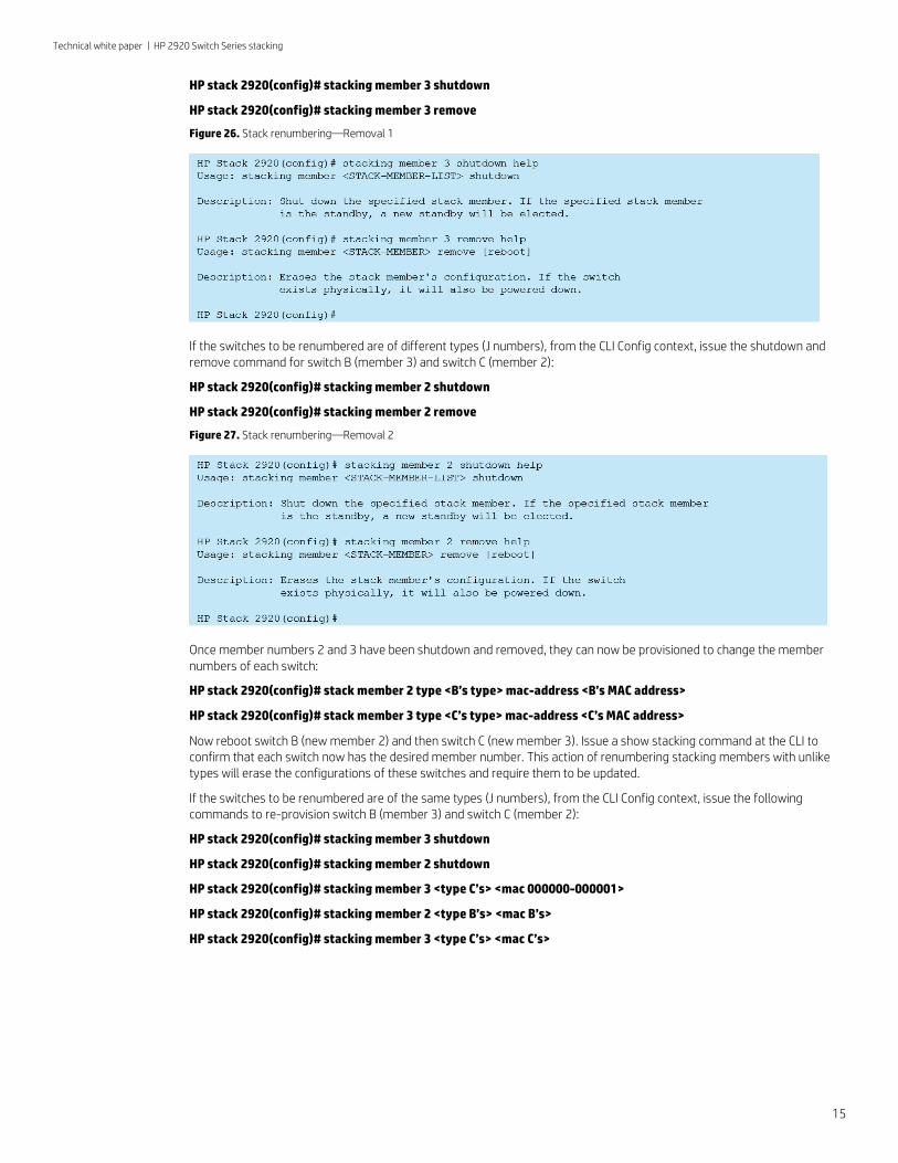
HP stack 2920(config)# stacking member 3 shutdown
HP stack 2920(config)# stacking member 3 remove
Figure 26. Stack renumbering—Removal 1
If the switches to be renumbered are of different types (J numbers), from the CLI Config context, issue the shutdown and remove command for switch B (member 3) and switch C (member 2):
HP stack 2920(config)# stacking member 2 shutdown
HP stack 2920(config)# stacking member 2 remove
Figure 27. Stack renumbering—Removal 2
Once member numbers 2 and 3 have been shutdown and removed, they can now be provisioned to change the member numbers of each switch:
HP stack 2920(config)# stack member 2 type <B’s type> mac-address <B’s MAC address>
HP stack 2920(config)# stack member 3 type <C’s type> mac-address <C’s MAC address>
Now reboot switch B (new member 2) and then switch C (new member 3). Issue a show stacking command at the CLI to confirm that each switch now has the desired member number. This action of renumbering stacking members with unlike types will erase the configurations of these switches and require them to be updated.
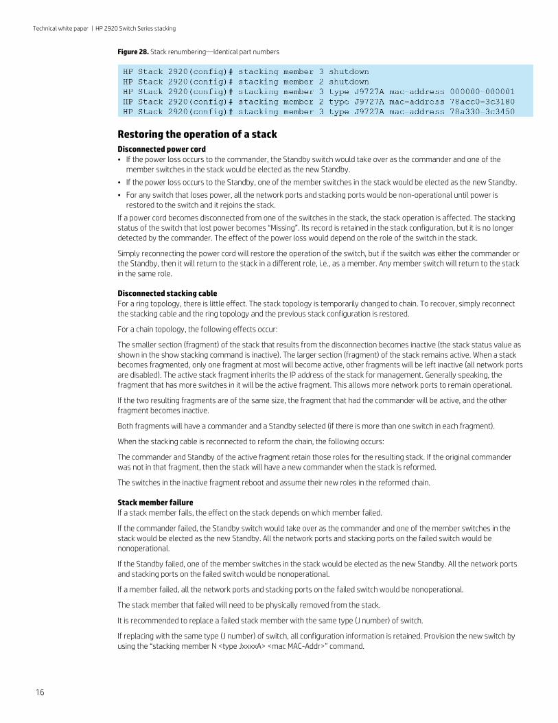
If the switches to be renumbered are of the same types (J numbers), from the CLI Config context, issue the following commands to re-provision switch B (member 3) and switch C (member 2):
HP stack 2920(config)# stacking member 3 shutdown
HP stack 2920(config)# stacking member 2 shutdown
HP stack 2920(config)# stacking member 3 <type C’s> <mac 000000-000001>
HP stack 2920(config)# stacking member 2 <type B’s> <mac B’s>
HP stack 2920(config)# stacking member 3 <type C’s> <mac C’s>
15
Technical white paper | HP 2920 Switch Series stacking
Figure 28. Stack renumbering—Identical part numbers
Restoring the operation of a stack Disconnected power cord • If the power loss occurs to the commander, the Standby switch would take over as the commander and one of the
member switches in the stack would be elected as the new Standby.
• If the power loss occurs to the Standby, one of the member switches in the stack would be elected as the new Standby.
• For any switch that loses power, all the network ports and stacking ports would be non-operational until power is restored to the switch and it rejoins the stack.
If a power cord becomes disconnected from one of the switches in the stack, the stack operation is affected. The stacking status of the switch that lost power becomes “Missing”. Its record is retained in the stack configuration, but it is no longer detected by the commander. The effect of the power loss would depend on the role of the switch in the stack.
Simply reconnecting the power cord will restore the operation of the switch, but if the switch was either the commander or the Standby, then it will return to the stack in a different role, i.e., as a member. Any member switch will return to the stack in the same role.
Disconnected stacking cable For a ring topology, there is little effect. The stack topology is temporarily changed to chain. To recover, simply reconnect the stacking cable and the ring topology and the previous stack configuration is restored.
For a chain topology, the following effects occur:
The smaller section (fragment) of the stack that results from the disconnection becomes inactive (the stack status value as shown in the show stacking command is inactive). The larger section (fragment) of the stack remains active. When a stack becomes fragmented, only one fragment at most will become active, other fragments will be left inactive (all network ports are disabled). The active stack fragment inherits the IP address of the stack for management. Generally speaking, the fragment that has more switches in it will be the active fragment. This allows more network ports to remain operational.
If the two resulting fragments are of the same size, the fragment that had the commander will be active, and the other fragment becomes inactive.
Both fragments will have a commander and a Standby selected (if there is more than one switch in each fragment).
When the stacking cable is reconnected to reform the chain, the following occurs:
The commander and Standby of the active fragment retain those roles for the resulting stack. If the original commander was not in that fragment, then the stack will have a new commander when the stack is reformed.
The switches in the inactive fragment reboot and assume their new roles in the reformed chain.
Stack member failure If a stack member fails, the effect on the stack depends on which member failed.
If the commander failed, the Standby switch would take over as the commander and one of the member switches in the stack would be elected as the new Standby. All the network ports and stacking ports on the failed switch would be nonoperational.
If the Standby failed, one of the member switches in the stack would be elected as the new Standby. All the network ports and stacking ports on the failed switch would be nonoperational.
If a member failed, all the network ports and stacking ports on the failed switch would be nonoperational.
The stack member that failed will need to be physically removed from the stack.
It is recommended to replace a failed stack member with the same type (J number) of switch.
If replacing with the same type (J number) of switch, all configuration information is retained. Provision the new switch by using the “stacking member N <type JxxxxA> <mac MAC-Addr>” command.
16
Technical white paper | HP 2920 Switch Series stacking
If replaced with a different type (J number) of switch, all configuration information is deleted. The switch must be removed from the stack using the “stacking member N remove” command, followed by a “stacking member N <type JxxxxA> <mac MAC-Addr>” command to provision the new switch. The new switch needs to be configured.
Reconnect all Ethernet ports, the same as on the failed stack member if replacing with the same type (J number) of switch.
If the replacement switch has a different version of software, it will be updated automatically to match the software version running on the stack.
Stack software update Load the new code onto the commander via TFTP, USB, or Xmodem. Once the new code is loaded, it will be copied to each of the members of the stack. In order for the stack of switches to run the new code, the stack must be rebooted. From a console session with the stack, issue the following command:
HP stack 2920# boot system
This causes the entire stack to be rebooted. Each unit is booted from its image, unless you specify otherwise with options to this command. Make sure that you boot from the image to which you downloaded. If you add a new member to an existing stack, the commander updates the new switches code to match the current stack code. Multiple versions of code is not supported across the stack members.
As the stack is rebooting, booting messages appear from the stack as it reboots.
You can confirm that the new code has been loaded on each stack member by using the member-context command for each member:
Syntax: member-context <STACK-MEMBER>
This command sets the CLI context so that subsequent commands apply to the stack member that is specified.
From the stack member context, you can see the switch software version that is running on that switch with either the show flash or show version command.
Creating a stack from standalone switches If the HP 2920 Switches have stacking modules installed and stacking enabled, each switch is a commander of a stack of one switch (itself). When stacking cables are connected between the switches, the switches will make up a new stack, and an election for the commander and Standby of the stack will occur. The switch which is elected Standby will reboot following the election. After each new switch is connected to the new stack, the switch will be rebooted.
Stacking notes When the HP 2920 Switch Series are configured as a stack, single IP management (classic ProVision stacking) is not supported.
Also, specific features reside on the commander only in a stack:
• The Auxiliary (USB) port functions only on the commander. The ability to upload/download software and configurations must be done using the commanders auxiliary (USB) port.
• The mode button on the commander functions for the entire stack and the mode button on a stack member functions only on that stack member.
The HP 2920 Switch Series do not support distributed trunking. However, link aggregation from different HP 2920 switches in a stack to a distribution or edge switch is supported.
Learn more at hp.com/networking
Sign up for updates hp.com/go/getupdated
Share with colleagues
Rate this document
© Copyright 2015 Hewlett-Packard Development Company, L.P. The information contained herein is subject to change without notice. The only warranties for HP products and services are set forth in the express warranty statements accompanying such products and services. Nothing herein should be construed as constituting an additional warranty. HP shall not be liable for technical or editorial errors or omissions contained herein.
4AA5-7121ENW, March 2015