Embed Size (px)
Citation preview
1
ContentsFeatures . . . . . . . . . . . . . . . . . . . . . . . . . . . . . . . . . . . . . . . . . . 1The CB Story . . . . . . . . . . . . . . . . . . . . . . . . . . . . . . . . . . . . A1
Licensing/Warning/Included Accessories . . . . . . . A1Controls and Indicators. . . . . . . . . . . . . . . . . . . . . . . . . A2Our Thanks to You . . . . . . . . . . . . . . . . . . . . . . . . . . . . . . A3
Customer Support . . . . . . . . . . . . . . . . . . . . . . . . . . . A3Operating Your CB Mobile Radio Installation/Connection . . . . . . . . . . . . . . . . . . . . . . . . . . . 2Turning On. . . . . . . . . . . . . . . . . . . . . . . . . . . . . . . . . . . . . . . . 4CB Antenna . . . . . . . . . . . . . . . . . . . . . . . . . . . . . . . . . . . . . . . 4Microphone Connector. . . . . . . . . . . . . . . . . . . . . . . . . . . . 5Squelch . . . . . . . . . . . . . . . . . . . . . . . . . . . . . . . . . . . . . . . . . . . 5Setting Squelch . . . . . . . . . . . . . . . . . . . . . . . . . . . . . . . . . . . 6Channel Selection . . . . . . . . . . . . . . . . . . . . . . . . . . . . . . . . . 8Channel 9/19. . . . . . . . . . . . . . . . . . . . . . . . . . . . . . . . . . . . . . 8CB/Weather . . . . . . . . . . . . . . . . . . . . . . . . . . . . . . . . . . . . . . . 8Dual Watch . . . . . . . . . . . . . . . . . . . . . . . . . . . . . . . . . . . . . . . 9Scan . . . . . . . . . . . . . . . . . . . . . . . . . . . . . . . . . . . . . . . . . . . . . . 9Soundtracker System . . . . . . . . . . . . . . . . . . . . . . . . . . . . 10Activating Soundtracker System . . . . . . . . . . . . . . . . . . 11S/RF Power Meter . . . . . . . . . . . . . . . . . . . . . . . . . . . . . . . . 12RX/TX Indicator LED. . . . . . . . . . . . . . . . . . . . . . . . . . . . . . 12Antenna Connector . . . . . . . . . . . . . . . . . . . . . . . . . . . . . . 13External Speaker . . . . . . . . . . . . . . . . . . . . . . . . . . . . . . . . . 13Power . . . . . . . . . . . . . . . . . . . . . . . . . . . . . . . . . . . . . . . . . . . 13Ignition Noise Interference . . . . . . . . . . . . . . . . . . . . . . . 14Temporary Mobile Operation. . . . . . . . . . . . . . . . . . . . . 14Operation to Receive/Transmit . . . . . . . . . . . . . . . . . . . 15Maintenance. . . . . . . . . . . . . . . . . . . . . . . . . . . . . . . . . . . . . 16Frequency Ranges . . . . . . . . . . . . . . . . . . . . . . . . . . . . . . . 18Specifications . . . . . . . . . . . . . . . . . . . . . . . . . . . . . . . . . . . 19Accessories . . . . . . . . . . . . . . . . . . . . . . . . . . . . . . . . . . . 20, 21Accessories Order Info . . . . . . . . . . . . . . . . . . . . . . . . . . . 22Warranty . . . . . . . . . . . . . . . . . . . . . . . . . . . . . . . . . . . . . . . . 23If You Think You Need Service . . . . . . . . . . Back Cover
Features of This Product
• 40 CB Radio Channels
• 10 Weather Channels
• SoundtrackerTMSystem
• Instant Channel 19 and 9
• 40 Channel Scan
• Dual Watch
• Front Firing Speaker
• Channel Saver Circuitry
• Dynamic Microphone
• 9 Foot Mic Cord
• Front Panel MicrophoneConnector
How to Use Your Cobra 18WXST II

2
Mounting and Connections
Select a location for the transceiver and micro-phone bracket that is convenient for operation.In automobiles, the transceiver is usually mountedto the underneath of the dash panel, with themicrophone bracket beside it.
1Hold the radio with mounting bracket in theexact location desired. Remove the mountingbracket and use it as a template to mark thelocation for the mounting screws.
2Drill necessary holes and secure mountingbracket in location.
3Connect the antenna cable plug to the recepta-cle marked “ANT”on the back of the unit.
Mounting andConnectionsNote
The transceiver is held in the
universal mounting bracket by
two thumb screws, permitting
adjustment at the most conve-
nient angle.
A universal mounting bracket
is supplied along with self tap-
ping screws and star washers.
To mount the transceiver:
OperationInstallation
CB Tranceiver
EXT. SPKR.
POWER13.8V DC
ANTENNA
CB Transceiver

3
4Connect the red lead of DC power cord to anaccessory 12 volt fuse.
5Connect the orange lead to a constant 12v fuse(ie: cigarette lighter or direct to battery)
6Connect the black lead to the negative side ofthe automobile.This is usually the chassis. Anyconvenient location with good electrical contact(remove paint) may be used.
7Mount the microphone bracket on right side ofthe transceiver or near it using two screws sup-plied.When mounting in an automobile, placethe bracket under the dash so the microphoneis readily accessible.
8Attach the 4-pin microphone cable to recepta-cle on front of unit and install unit in bracket-securely.
Mounting andConnectionsNote
Before installing the CB radio,
visually check the vehicle bat-
tery connections to determine
which battery terminal, posi-
tive or negative (positive is the
larger of the two) is grounded
to the engine block
(or chassis).
OperationInstallation
SQUELCHVOLUME
DW SCAN S 1 3 5 9 +30
P .5 1 2 3 4
CB / WEATHER
CH 9 / 19
1

4
Turning on
Turn volume control clockwise to turn power onand set the desired listening volume.
CB Antenna
Only a properly matched antenna system willallow maximum power output.
In mobile installations (cars, trucks, boats, etc.),an antenna system that is non-directional should be used.
When installed in a boat, the transceiver will notoperate at maximum efficiency without a groundplate unless the vessel has a steel hull. Beforeinstalling the transceiver in a boat, consult yourdealer for information regarding an adequategrounding system.
Turning onYour Radio
Operation
CB Antenna
OFF
Note
Cobra loaded-type antennamodels HGA 1000, HGA 1500,and HGA 2000 are highly rec-ommended for most installa-tions. Consult your Cobra deal-er for further details (or seeorder form at the back of this book).
3-Way Combination Antennasare available which allow oper-ation of all three bands (AM-FM& CB), using a single antenna.However, use of this type ofantenna usually results in lessthan normal transmit andreceive range when comparedto a standard-type "SingleBand" antenna designed for CB only.

5
Microphone Connector
Allows for convenient removal of the microphoneplug when storage is required.The microphoneMUST be connected to the unit at all times when inuse, for proper operation.
Squelch
This control is used to cut off or eliminate receiverbackground noise in the absence of an incomingsignal. Adjust until the receiver noise disappears.This will require the incoming signal to be slightlystronger than average receiver noise. Further clock-wise rotation will increase the threshold levelwhich a signal must overcome in order to be heard.Only strong signals will be heard at a maximumclockwise setting.
MicrophoneConnector
Operation
OFF
OFF
Squelch
SHIELD
AUDIO
RX
TX
1
23
4

NOISE
WEAK SIGNALS
MEDIUM SIGNALS
STRONG SIGNALS
GA
TE
CL
OS
ED
NOISE
WEAK SIGNALS
MEDIUM SIGNALS
STRONG SIGNALS
NOISE
WEAK SIGNALS
MEDIUM SIGNALS
STRONG SIGNALS
GA
TE
O
PE
N
NOISE
WEAK SIGNALS
MEDIUM SIGNALS
STRONG SIGNALS
6
Operation
Gate open
Gate closed
SettingSquelch
Setting Squelch Squelch is the “control gate” for incoming signals.
1. Full clockwise rotation closes the gate allowing only very strong signals to enter.
2. Full counterclockwise rotation opens the “gate”allowing all signals in.
OFF
OFF

7
3. To achieve the Desired Squelch Setting (DSS),turn the Squelch control counterclockwise untilyou hear noise. Now turn the control clockwisejust until the noise stops. This is the DSS setting.
Operation
NOISE
WEAK SIGNALS
MEDIUM SIGNALS
STRONG SIGNALS
GA
TE
Gate set to Desired Squelch Setting (DSS)
OFF

ChannelSelection
8
Set CB or WX Mode
Set on CB mode. Rotate channel knob clockwiseuntil desired channel is displayed.
Channel 9/Channel 19
Press CH 9/19 to obtain instant access to emergencychannel 9. Press again for information CH 19.
CB/Weather
CB mode is for normal CB operation. PressCB/Weather again and select active Weather channelin your area.
Operation
OFF
OFF
PRESS AND RELEASE
OFF
Channel 9/Channel 19
CB Weather
PRESS AND RELEASE
9
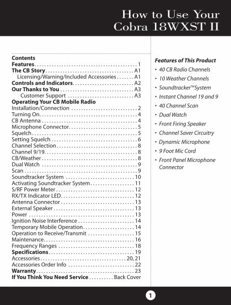
Dual Watch
This features allows the user to scan between twoselected channels.
1. Select first channel, CB mode.
2. Press and hold DW until LED begins flashing andbeeps once.
3. Select second channel. Press DW until LED lightssteady and radio beeps twice. Two channels arenow stored in DW memory.
Scan
Press and release SCAN button to activate CB scanmode. If the radio is squelched, radio begins to scan.
When scan is interrupted by a signal, scan stops andholds until loss of signal. Press PTT on mic to stopscan function. Press Scan to restart CB scan.
Operation
Dual WatchNote
The radio needs to be
squelched before DW can
monitor both channels.
OFF
ScanNote
On some channels squelch
setting might have to be re-set.
PRESS AND HOLD
OFF
PRESS AND RELEASE

10
The SoundTracker System reduces noise whileleaving the signal intact in the reception mode.In the transmission mode, it strengthens the sig-nal, providing you with a significant reduction innoise on reception and transmission.
How SoundTracker works
On Reception–“Cuts Noise Coming In”With a normal CB, distant signals fall below thesquelch level and are unintelligible. With aSoundTracker CB, the noise level is cut by up to90%, which increases the signal-to-noise ratioand dramatically improves signal clarity. This alsoallows you to significantly reduce the squelchlevel, which greatly expands your listening range.
On Transmission–“Strengthens Signals Going Out”A SoundTracker CB strengthens the transmit sig-nal by more effectively using the available RFpower output of the CB. The result is improvedtransmission signal clarity and an expandedtransmission range.
SoundtrackerSystem
Operation
USPat. No. 6,038,429

11
Activating Soundtracker
1. Press the SoundTracker button on the upperleft side of front panel. A red indicator will illuminate when the SoundTracker system isengaged.
ActivatingSoundtracker
Operation
OFF
PUSH AND RELEASE

12
S/RF Power Meter
Shows relative transmitter RF output power andinput signal strength when receiving.The LED(Light Emitting Diode) segments glow green toamber to red...this indicates receive or transmitactivity.
RX/TX Indicator LED
RX indicator will light when in the receive mode.TX indicator lights when in transmit mode.
When weather channel is selected,WX indicator isilluminated, and the channel is displayed.
S/RFPowerMeter
Operation
OFF
OFF
RX/TXIndicator LED

13
Rear Panel
Antenna Connector. This female connector per-mits connection of the transmission line cablemale connector to the transceiver.
External Speaker. The External Speaker Jack isused for an external speaker. The external speak-er should have 8-ohm impedance and be ratedto handle at least 4.0 watts. When the externalspeaker is plugged in, the internal speaker isautomatically disconnected.
Power: This cable is permanently attached to theradio. If you wish to remove the radio after instal-lation, disconnect at fuse holder and ground connector.
AntennaConnector
Operation
ExternalSpeaker
EXT. SPKR.
POWER13.8V DC
ANTENNA
Power
Note
Cobra external speakers are
rated 15 watts

14
Ignition Noise Interference
Use of a mobile receiver at low signal levels is nor-mally limited by the presence of electrical noise.Under most operating conditions, when signallevel is adequate, the background noise does notpresent a serious problem. Also, when extremelylow level signals are being received, the transceivermay be operated with vehicle engine turned off.The unit requires very little current and thereforewill not significantly discharge the vehicle battery.
Even though this radio has an automatic noise lim-iter, in some installations ignition interference maybe high enough to make good communicationsimpossible. Consult your COBRA dealer or a 2-wayradio technician for help in locating and correctingthe source of severe noise.
Temporary Mobile Operation
For temporary mobile operation, you may want topurchase an additional cigarette lighter adapterfrom your COBRA dealer.This adapter and a mag-netic mount antenna allow you to quickly "install"your transceiver for temporary use.
Operation
Ignition NoiseInterference
TemporaryMobileOperation
Note
Red and Orange wires are con-
nected to positive side of socket
center tip. Black wire is connect-
ed to negative side contacts.
Note
Radio resets to CH 9 when con-
nected to cigarette lighter plug.
EXT
ANT
13.8V DC
PA
Note
When using the unit with cig-
arette adapter, turn off when
not in use to avoid draining
the battery.

15
Operating Procedure to Receive1. Be sure that power cord, antenna and microphone are connected to the
proper connectors before proceeding further. The weather switch shouldbe in the "CB" position.
2. Turn the radio ON by rotating the VOLUME CONTROL clockwise.3. Rotate SQUELCH CONTROL counterclockwise until incoming signal is
heard.4. Select the desired channel.5. Set VOLUME CONTROL to a comfortable listening level.6. Engage the SoundTracker system by depressing the button labeled ST.Listen to the background noise from the speaker. Turn the SQUELCH CON-TROL slowly clockwise until the noise JUST disappears (no signal should bepresent). Leave the control at this setting. The squelch is now properlyadjusted. The receiver will remain quiet until a signal is actually received. Donot advance the control too far, or some of the weaker signals will not beheard. The revolutionary SoundTracker system allows you to reduceunwanted background noise (static) and increase the signal for betterreception.Operating Procedure to Transmit1. Select the desired channel.2. The receiver and transmitter are controlled by the press-to-talk switch on
the microphone. Press the switch and the transmitter is activated; releaseswitch to receive. When transmitting (on a clear channel), hold the micro-phone two inches from the mouth and speak clearly in a normal voice.
Be sure the antenna is properly connected to the radio before transmit-ting. Prolonged transmitting without an antenna, or a poorly matchedantenna, could cause damage to the transmitter.
Operation

16
Maintenance/Adjustment
Maintenance
Maintenance and Adjustment
Your COBRA CB transceiver is specificallydesigned for the environment encountered inmobile installations. The use of all solid state cir-cuitry and its light weight result in high reliabili-ty. Should a failure occur, however, review the fol-lowing, then if necessary, replace parts only withidentical parts. Do not substitute.
1. Check connections to the source of power andmake sure it is the 13.8 VDC required to oper-ate your radio.
2. Check the fuses in the DC power cord. Themain power lead (red & orange wire) has a 2amp 3AG type fuse in its holder. Use only theabove specified type and size fuse for maxi-mum protection. Failure to do so, will void thewarranty.
3. Make certain the microphone is properlyplugged in.
4. Make certain the antenna is properly assem-bled and connected.
If you are unable to correct the problem, refer tothe SERVICE INSTRUCTIONS at the end of thismanual for the correct procedure for warrantyand post-warranty service from COBRA.

Permitted: "A tornado sighted six miles of town."Not Permitted : "This is observation post number 10.No tornado sighted."
Warning
17
Channel 9EmergencyMessages
Replacement Warning
Replacement or substitution of certain parts withreplacements other than those recommended byCobra may be a violation of the technical regula-tions of Part 95 of the FCC rules, or of TypeAcceptance requirements of Part 2 of said rules.
When making adjustments, be sure to re-readapplicable portions of this instruction manual tomake certain you are following correct procedureand that the radio was properly installed, etc.
A Few Rules That Should Be Obeyed1. You are not allowed to carry on a conversation with
another station for more than five minutes at a time with-out taking a one-minute break to give others a chance touse the channel.
2. You are not allowed to blast others off the air by overpow-ering them with illegally amplified transmitter power orillegally high antennas.
3. You can't use CB to promote illegal activities.4. You are not allowed to use profanity.5. You may not play music in your CB.6. You may not use your CB to sell merchandise or profes-
sional service.
Use Channel 9 For Emergency Messages Only
The FCC gives the following examples of permit-ted and prohibited types of communications foruse on Channel 9. These are guidelines and arenot intended to be all-inclusive.
A Few RulesYou ShouldKnow

Accessories
18
Frequency RangesThe COBRA 18 WX ST II transceiver represents one ofthe most advanced AM two-way radios used as a ClassD station in the Citizens Radio Service.This unit featuresadvanced Phase Lock Loop (PLL) circuitry providingcomplete coverage of all 40 CB channels and all 10weather channels as shown below.
1 26.965 21 27.2152 26.975 22 27.2253 26.985 23 27.2554 27.005 24 27.2355 27.015 25 27.245
6 27.025 26 27.2657 27.035 27 27.2758 27.055 28 27.2859 27.065 29 27.29510 27.075 30 27.305
11 27.085 31 27.31512 27.105 32 27.32513 27.115 33 27.33514 27.125 34 27.34515 27.135 35 27.355
16 27.155 36 27.36517 27.165 37 27.37518 27.175 38 27.38519 27.185 39 27.39520 27.205 40 27.405
Channel ChannelCB Freq. CB Freq.Channel In MHz Channel In MHz
WeatherWeather Freq.Channel In MHz
1 162.5502 162.4003 162.4754 162.4255 162.4506 162.5007 162.5258 161.6509 161.77510 163.275

19
Specifications
Specifications
GENERALCHANNELS . . . . . . . . . . . . . . . . . . . . . . . . CB - 40 CH
WEATHER – 10CHFREQUENCY RANGE. . . . . . . . . . . . . . . . CB - 26.965 TO 27.405 MHZ
WEATHER – 161.650 TO 163.275FREQUENCY TOLERANCE . . . . . . . . . . . 0.005 %FREQUENCY CONTROL . . . . . . . . . . . . PLL (PHASE LOCK LOOP) SYNTHESIZEROPERATING TEMPERATURE RANGE . . . . . . . . . . . . . . . . . . . . . . . . . . . . -30° C TO + 65° CMICROPHONE . . . . . . . . . . . . . . . . . . . . . PLUG-IN DYNAMICINPUT VOLTAGE . . . . . . . . . . . . . . . . . . . 13.8VDC nom. (negative ground) CURRENT DRAIN TRANSMIT: AM FULL MOD., 1.4A (MAXIMUM)
RECEIVE: SQUELCHED, 0.9 A;FULL AUDIO OUTPUT, 1.2A (NOMINAL)
SIZE . . . . . . . . . . . . . . . . . . . . . . . . . . . . . .6-7/8” D X 6-3/4”W X 1-7/8” HWEIGHT . . . . . . . . . . . . . . . . . . . . . . . . . . . .4.25 LBS.ANTENNA CONNECTOR . . . . . . . . . . . .UHF; SO-239METER . . . . . . . . . . . . . . . . . . . . . . . . . . . . .LED; INDICATES RELATIVE POWER
OUTPUT AND RECEIVED SIGNAL STRENGTH
TRANSMITTERPOWER OUTPUT . . . . . . . . . . . . . . . . . . .4 WATTSMODULATION . . . . . . . . . . . . . . . . . . . . .AM (AMPLITUDE MODULATION)FREQUENCY RESPONSE . . . . . . . . . . . .300 TO 3000 HZOUTPUT IMPEDANCE . . . . . . . . . . . . . . .50 OHMS, UNBALANCED
RECEIVERSENSITIVITY . . . . . . . . . . . . . . . . . . . . . . . .LESS THAN 1 µV FOR 10dB (S+N) SELECTIVITY . . . . . . . . . . . . . . . . . . . . . . .6 dB @ 7 KHZ, 60 DB @ 10KHZIMAGE REJECTION . . . . . . . . . . . . . . . . . .60 dB, TYPICALADJACENT-CHANNEL REJECTION . . .50 dB, TYPICALATOMATIC NOISE LIMITER . . . . . . . . . .BUILT-IN
WEATHERSENSITIVITY . . . . . . . . . . . . . . . . . . . . . . . .LESS THAN 1 µV FOR 12 dB SINADIF-FREQUENCY . . . . . . . . . . . . . . . . . . . . .DUAL CONVERSIONAUDIO OUTPUT . . . . . . . . . . . . . . . . . . . .MAXIMUM 1 W AT 10% DISTORTIONFREQUENCY RESPONSE . . . . . . . . . . . .300 – 3000 HZ AT -6 dB

20
Accessories
Replacement MountingBracket
251-199-9-001 $4.50
Replacement Thumb Screws
634-081-9-001 $0.60
Replacement MicrophoneBracket
741-080-9-001 $0.45
4-Pin Power Microphone
HG M75 $25.95
4-Pin Noise CancelingMicrophone
HG M77 $30.95
4-Pin Replacement DynamicMicrophone
HG M73 $19.95
4 Pin Premium Noise-Cancelling Microphone
HG M84 $74.95
4 Pin Premium Noise-Cancelling MicrophoneWood GrainHG M84W $74.95
5 Pin Premium Noise-Cancelling Microphone
HG M85 $74.95
You can find quality Cobra products and accessories atyour local Cobra dealer, or in the U.S.A., you can orderdirectly from Cobra. See ordering info on page 22.

38” Base Loaded MagnetMount Antenna
HG A1500 $46.95
54” Base Loaded MagnetMount Antenna
HG A2000 $99.95
21” Base Loaded MagnetMount Antenna
HG A1000 $28.95
Dynamic External Speaker
HG S100 $21.95
Noise Canceling ExternalSpeaker
HG S300 $28.95
Dynamic Noise CancelingWith Talk Back ExternalSpeaker
HG S500 $32.95
Fiberglass Whip Replacement Antenna
33 FFoooott HG A300 $28.95Black, Red, White, Gold44 FFoooott HG A400 $29.95Black, Red, White44 11//22 FFoooott HG A450 $30.95Black, Red, White, Gold
Accessories
62” Center-Load Replacement Antenna
HG A6000 $89.95Black/Clear, Black, Red, White, Gold
21

Accessories Order Info
22
251-199-9-001 Replacement Mounting Bracket634-081-9-001 Replacement Thumb Screws741-080-9-001 Replacement Microphone BracketHG A1000 21”Base Loaded Magnetic Mount AntennaHG A1500 38”Base Loaded Magnetic Mount AntennaHG A2000 54”Base Loaded Magnetic Mount AntennaHG M84 4 Pin Premium Noise-Cancelling MicrophoneHG M84W 4 Pin Premium Noise-Cancelling Mic Wood gr HG M85 5 Pin Premium Noise-Cancelling MicrophoneHG M73 Replacement Dynamic MicrophoneHG M75 Power Microphone HG M77 Noise Canceling/Power MicrophoneHG S100 Dynamic External SpeakerHG S300 Noise Canceling External SpeakerHG S500 Dynamic Noise Canceling
With Talk Back External SpeakerHG A300 Fiberglass Whip Replacement Antenna
Black, Red, White, GoldHG A400 Fiberglass Whip Replacement Antenna
Black, Red, White, GoldHG A450 Fiberglass Whip Replacement Antenna
Black, Red, White, GoldHG A6000 62”Center-Load Replacement Antenna
Black/Clear, Black, Red, White, Gold
Item # Description
Ordering From U.S.A.Call 773-889-3087 for pricing or visit www.cobra.com.
For Credit Card OrdersCall 773-889-3087 [Press one from the main menu] 8:00 a.m. to 6:00 p.m. Central Time, Monday through Friday.
Make Check or Money Order Payable ToCobra Electronics, Attn: Accessories Dept., 6500 West Cortland Street, Chicago, IL 60707 U.S.A.
To Order OnlinePlease visit our website: www.cobra.com

23
Limited Two Year WarrantyLimited Warranty
COBRA ELECTRONICS CORPORATION warrants that its COBRACB Transceiver, and the component parts thereof, will be free ofdefects in material and workmanship for a period of two (2) yearsfrom the date of consumer purchase.This warranty may beenforced by the first consumer purchaser, provided that the prod-uct is utilized within the U.S.A.
COBRA will, without charge, repair or replace, at its option, a defec-tive CB Transceiver upon delivery to the COBRA factory ServiceDepartment, accompanied by proof of the date of first consumerpurchase, such a duplicated sales receipt.
You must pay initial shipping charges required to ship the prod-uct for warranty service, but the return charges will be at COBRA’Sexpense, if the product is repaired or replaced under warranty.
Exclusions: This limited warranty does not apply; 1) to any prod-uct damaged by accident; 2) in the event of misuse or abuse ofthe product or as a result of unauthorized alterations or repairs; 3)if the serial number has been altered, defaced or removed; 4) if theowner of the product resides outside the U.S.A.
All implied warranties, including warranties of mer-chantability and fitness for a particular purpose are limitedin duration to the length of this warranty.
COBRA shall not be liable for any incidental, consequentialor other damages; including, without limitation, damagesresulting from loss of use or cost of installation.
Some states do not allow limitations on how long an impliedwarranty lasts and/or do not allow the exclusion or limita-tion of incidental or consequential damages, so the abovelimitations may not apply to you.
Cobra ElectronicsCorporation
6500 West Cortland StreetChicago, Illinois 60707 USA
Cobra®, HighGear®, SoundTracker®, Nothing Comes Close to aCobra® and the snake design are registered trademarks of CobraElectronics Corporation, USA. Cobra Electronics Corporation™ isa trademark of Cobra Electronics Corporation, USA.

The Cobra line of quality products also includes:
• CB Radios
• microTALK® Radios
• Radar/Laser Detectors
• Safety Alert® Traffic Warning Systems
• Handheld GPS Receivers
• Mobile GPS Navigation Systems
• HighGear® Accessories
• CobraMarine® VHF Radios
• CobraMarine® Chartplotters
• Power Inverters
• Accessories
Nothing Comes Close to a Cobra®

Cobra Electronics Corporation6500 West Cortland StreetChicago, IL 60707 USA
©2006 Cobra Electronics Corporation
Printed in China
Part No. 480-315-P-001
For technical assistance, please call our Automated Help Desk which can assist you by answering the most frequently asked questions about Cobra products.
(773) 889-3087 24 hours a day, 7 days a week.
A Consumer Service Representative can be reached through this same number 8:00 am - 6:00 pm, Monday through Friday, Central Time.
Technical assistance is also available on-line in the Frequently Asked Questions (FAQ) section at www.cobra.com or by e-mail to [email protected]
If you think you need service call 1.773.889.3087
If your product should require factory service please call Cobra first before sending in your unit.This will ensure the fastest turn-around time on your repair.
You may be asked to send your unit to the Cobra factory. It will be necessary to furnish the follow-ing in order to have the product serviced and returned.
1. For Warranty Repair include some form of proof-of-purchase, such as a mechanical reproductionor carbon of a sales receipt. If you send the original receipt it cannot be returned.
2. Send the entire product.
3. Enclose a description of what is happening with the unit. Include a typed or clearly print nameand address of where the unit is to be returned.
4. Pack unit securely to prevent damage in transit. If possible, use the original packing material.
5. Ship prepaid and insured by way of a traceable carrier such as United Parcel Service (UPS) or FirstClass Mail to avoid loss in transit to: Cobra Factory Service, Cobra Electronics Corporation, 6500W. Cortland St., Chicago, IL 60707.
6. If the unit is in warranty, upon receipt of your unit it will either be repaired or exchangeddepending on the model. Please allow approximately 3 to 4 weeks before contacting us for status. If the unit is out of warranty a letter will automatically be sent informing you of the repair charge or replacement charge. If you have any questions, please call 1.773.889.3087 for assistance.
If You Think You Need Service

18 WX ST IIMobile Radio
with System
Operating Instructions for your
18 WX ST II
Nothing Comes Close to a Cobra®

CB Tranceiver
“Ingenious Products for Easier Communication.”
18 WX ST IIMobile Radio
with System
Operating Instructions for your
18 WX ST II
18 WX ST II
OFF
OFF
A1
The Citizens Band Story
4
5
21
3
The Citizens Band lies between the shortwave broadcastand 10-meter Amateur radio bands, and was establishedby law in 1949. The Class D two-way communicationsservice was opened in 1959. (CB also includes a Class Acitizens band and Class C remote control frequencies.)
FCC RegulationsFCC regulations permit only "transmissions" (one-partyto another) rather than" broadcast" (to a wide audience).Thus, advertising is not allowed on CB channels becausethat is "broadcasting".
FCC WarningsAll transmitter adjustments other than those suppliedby the manufacturer as front panel operating controls,must be made by, or under the supervision of, the holderof an FCC-issued general Radio-Telephone Operator’sLicense.
Replacement or substitution of transistors, regular di-odes or other parts of a unique nature, with parts otherthan those recommended by Cobra, may cause violationof the technical regulations of Part 95 of the FCC Rules,or violation of Type Acceptance requirements of Part 2of the Rules.
You should read and understand Part 95 (included withthis unit) of the FCC Rules and Regulations, before oper-ating your Cobra radio, even though the FCC no longerrequires you to obtain an operator’s license.
What’s included with your CB Radio:1. CB transceiver 6. FCC rules2. Microphone . (not pictured)3. Transceiver bracket 1.4. Microphone bracket5. Operating Manual

18 WX ST II
OFF
OFF
EXT. SPKR.
POWER13.8V DC
ANTENNA
A2
Controls and Indicators
1
712
6
2 3 4 5
1314
8
11
151. Microphone Connector.
2. Off/On/Volume.
3. Squelch.
4. Channel 9/Channel 19
5. CB/Weather
6. Channel Selector Button.
7. LED Channel Display.
8. S/RF Power Meter.
9. WX Indicator LED.
10. TX Indicator LED.
11. RX Indicator LED.
12. Scan Button.
13. SoundTracker™ Button.
14. Dual Watch Button.
15. Microphone
Back Side
16. Antenna Connector
17. External Speaker Connector
18. Power Cord
910
16
17
18

Thank you for purchasing the Cobra 18 WX ST IICB Radio Transceiver. Properly used, this Cobraproduct will give you many years of reliable service.
“Cuts Static coming in, adds Punch going out!”
Technology that dramatically improves thetransmission and reception of CB radio signals.
The revolutionary SoundTrackerTM System recon-figures the transmission signal which allows it tobe transferred more effectively through clutteredairwaves.
At the same time, it significantly reduces theamount of static on all incoming CB signals.
The end result is a clearer, cleaner soundingreception of signals and a more powerful transmission which dramatically improveCB communications.
Customer Support
Should you encounter any problems with thisproduct, or not understand its many features,please refer to this owner’s manual. If, after refer-ring to the manual, you still need help, call CobraCustomer Service at 773.889.3087.
Cobra Customer ServiceLive operators are available M-F 8:00 am –6:00 pm Central Time at773.889.3087Automated TechnicalAssistance available 24hours a day, seven days aweek. E-mail questions to:[email protected]
Cobra on the World WideWeb: Frequently AskedQuestions (FAQ) can befound at: www.cobra.com
A3
Our Thanks to You