Embed Size (px)
Citation preview

How to Program
WONDOM
Products with ADAU1701
through SigmaStudio
By Sure Electronics

ADAU1701 is a high performance digital signal processor of Analog Devices Inc. We have developed many products
integrated with ADAU1701, which support programming via SigmaStudio after connection with our programming boards.
This document is meant to show you how to program WONDOM ADAU1701 DSP products with SigmaStudio.
We need to know the products and
software that we need before start.
In this part, we will focus on introduction
of WONDOM products integrated with
DSP and ICP programmers.
In this part, we will give you a brief
introduction of SigmaStudio
interface and some documents you
may need.
We will demonstrate to write
basic programs based on
WONDOM DSP products for
your reference, so that you can
get started quickly.
We need to know the products and software that we
need before start.
In this part, we will focus on introduction of WONDOM
products integrated with DSP and ICP programmers.
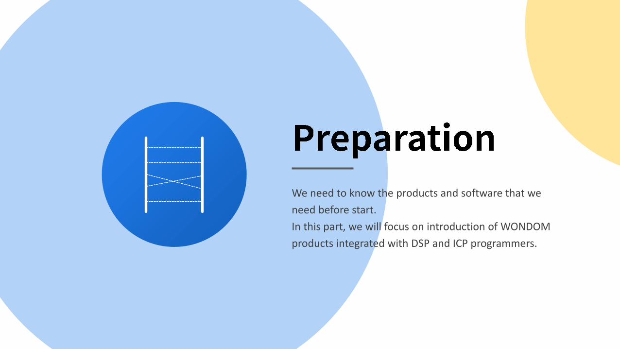
The following are the products list of WONDOM products that are integrated with ADAU1701 DSP.
The functions vary to different products. Please select to your requirements.
Model DescriptionSS
ProgramAPP
ControlPC UI
Control
APM2 2-in, 4-out ADAU1701 DSP Kernel Board Y Y Y
JAB3 Mono / Stereo Class D Audio Amplifier Board Integrated with ADAU1701 DSP Y Y Y
JAB3+ Mono / Stereo Audio Amplifier Board Integrated with ADAU1701 DSP & BT V5.0 Y N Y
JAB44CH 30W Audio Amplifier Board Integrated with ADAU1701 DSP & BT V5.0, Supporting Configuration as 4.0 / 2.1 / 2.0 / 0.2 Output Mode
Y N Y
JAB54CH 100W Audio Amplifier Board Integrated with ADAU1701 DSP & BT V5.0, Supporting Configuration as 4.0 / 2.1 / 2.0 / 0.2 Output Mode
Y N Y

Model DescriptionSS
ProgramAPP
ControlPC UI
Control
ICP1 In-Circuit Programmer Y N N
ICP3 In-Circuit Programmer Integrated with Bluetooth BLE Y Y N
ICP5 In-Circuit Programmer Integrated with Bluetooth BLE & USB to UART Y Y* Y
Different ICP products support different functions. Please select to your requirements.
* The function only works when both products with ADAU1701 DSP and the ICP board support it, i.e. JAB3+ doesn’t support APP control, so even if you buy
ICP3 or ICP5 that supports APP control, JAB3+ still cannot support APP control after connection.

If you never install SigmaStudio, you can click the following link for download and installation. https://www.analog.com/sigmastudiodownload
It’s highly suggested that you remember the following link for official support. You can find algorithm information, tutorials, examples and other useful documentation as reference.SigmaStudio and SigmaDSP Documentation [Analog Devices Wiki]
In this part, we will give you a brief introduction of
SigmaStudio interface and some documents you
may need.

We will take connection of APM2 and ICP3 as an example here.
Connection based on other products are similar.
Connect ICP3 to PC, run SigmaStduio, create a new project, drag “USBi”, “ADAU1701”, “E2Prom”, complete logic connection to see if ICP3 has been recoginizedsuccessfully;
Connect APM2 & APM3, connect audio source and speakers, power up the system
Connect APM2 with ICP3 through a 6-pin cable Write program

Brief Interface Introduction
Devices Hardware ConfigurationDrag corresponding DSP & USB communication
module and complete logic connection
ICs/DSPs & USB Communication module

Hardware RegisterThis page appears when ADAU1701 is
dragged into hardware configuration section. GPIOs are set here.
Brief Interface Introduction
Devices
ICs/DSPs & USB Communication module

Schematic Toolbox
Schematic Design
Drag desired algorithm here and complete the logic connection
Algorithms & Modules
Brief Interface Introduction

WONDOM products integrated with ADAU1701 DSP are equipped with terminal interfaces for various functions. You can
get the detailed introduction in datasheet. Please find the documentation in the detailed product page on our website.
APM2 AA-AP23122 ADAU1701 Kernel Board
JAB3 Audio Amplifier Boards Integrated with ADAU1701 DSP
JAB3+ Audio Amplifier Boards Integrated with ADAU1701 DSP & Bluetooth V5.0
JAB4 4CH 30W Audio Amplifier Boards Integrated with ADAU1701 DSP & Bluetooth V5.0
JAB5 4CH 100W Audio Amplifier Boards Integrated with ADAU1701 DSP & Bluetooth V5.0

ICP Programmer Pin Definition
ICP series is self-developed programming board, which can be used with WONDOM DSP products. After connection with
ICP programmer, DSP products can support programming and remote control (It’s up to specific product). Please find the
user guide in the detailed product page on our website.
Model Document Video
ICP1 WODNOM ICP1 User Guide - Programming -
ICP3 WODNOM ICP3 User Guide – Programming & APP Control Watch
ICP5 WODNOM ICP5 User Guide – Programming, APP & PC UI Control -

Products Demo Program Document you may need
APM2 APM2_SigmaStudio.dspproj Download
JAB3 - Mono JAB3_SigmaStudio_MONO.dspproj
Download
JAB3 - Stereo JAB3_SigmaStudio_STEREO.dspproj
JAB3+ JAB3+_Stereo_ADAU1701_DEMOProgram.dspproj Download
JAB4 JAB4_ADAU1701_DEMOProgram.dspproj -
JAB5 JAB5_ADAU1701_DEMOProgram.dspproj Download
Here are the demo programs for the products. You can download them for reference. The demo program is only for
demonstration of signal flow chart.

WONDOM products are developed based on ADAU1701 DSP. We have made use of ADAU1701 resources to provide basic
functions like audio input & output, control. Therefore, it’s necessary for us to understand the correspondence
relationship between the hardware and program for further development.
Model Document Video
APM2 The correspondence between APM2 hardware and program -
JAB3 How to develop JAB3 & Integrated ADAU1701 DSP Watch
JAB3+ How to program JAB3+ through SigmaStudio Watch
JAB5 How to program JAB5 through SigmaStudio Watch

Products Original Firmware
APM2 Download
JAB3 - Mono Download
JAB3 - Stereo Download
JAB3+ - Mono Download
JAB3+ - Stereo Download
Here are the demo programs for the products. You can download them for reference. The demo program is only for
demonstration of signal flow chart.
Products Original Firmware
JAB4 Download
JAB5 Download

We will demonstrate to write basic programs based on
WONDOM DSP products for your reference, so that you
can get started quickly.
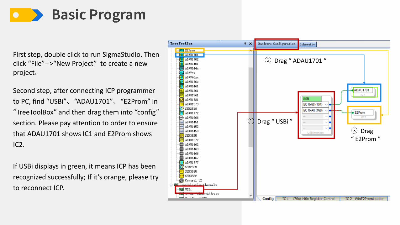
First step, double click to run SigmaStudio. Then click “File”-->“New Project” to create a new project
Second step, after connecting ICP programmer
to PC, find “USBi” “ADAU1701” “E2Prom” in
“TreeToolBox” and then drag them into “config”
section. Please pay attention to order to ensure
that ADAU1701 shows IC1 and E2Prom shows
IC2.
If USBi displays in green, it means ICP has been
recognized successfully; If it’s orange, please try
to reconnect ICP.
Drag “ USBi ”
Drag “ ADAU1701 ”
Drag“ E2Prom ”

Let’s write a bypass program at first.
Click “Schematic” to enter schematic
design section
Drag “IO”-“Input”-“Input” to design
section from “TreeToolBox” . We can see 0
& 1 of input module are ticked. They are
for analog input.
Drag “IO”-“Output”-“Outnput” . We want
stereo output, so we need to drag two
output modules. Stereo output on APM3
are corresponded with DAC0 & DAC1.
Complete logic connection between input
and output modules.
( )
Click “Schematic”
Drag input module
Drag output module
Connection
Basic Program – Bypass
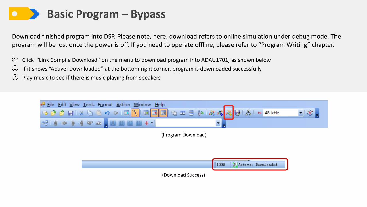
Download finished program into DSP. Please note, here, download refers to online simulation under debug mode. The program will be lost once the power is off. If you need to operate offline, please refer to “Program Writing” chapter.
Click “Link Compile Download” on the menu to download program into ADAU1701, as shown below
If it shows “Active: Downloaded” at the bottom right corner, program is downloaded successfully
Play music to see if there is music playing from speakers
(Program Download)
(Download Success)
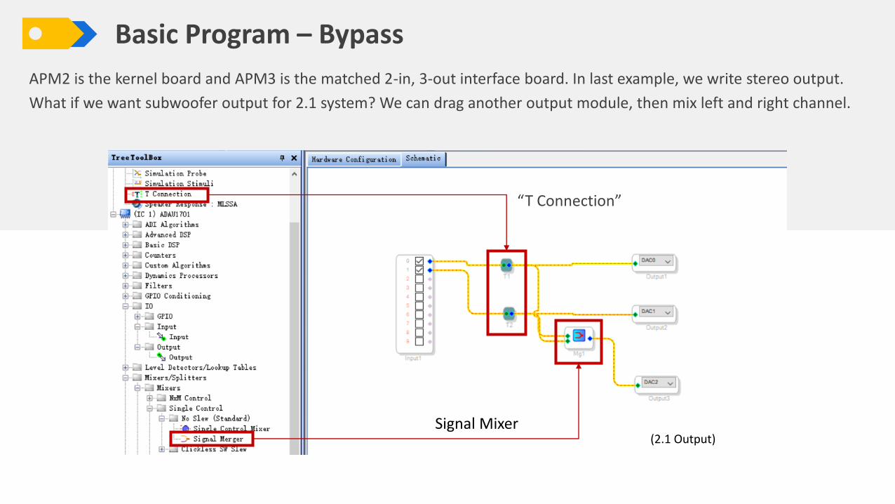
APM2 is the kernel board and APM3 is the matched 2-in, 3-out interface board. In last example, we write stereo output.
What if we want subwoofer output for 2.1 system? We can drag another output module, then mix left and right channel.
Signal Mixer
“T Connection”
(2.1 Output)
Basic Program – Bypass

Basic Program – Volume Control
How to adjust overall volume? We need to make use of “Volume Controls” modules. There are many functions in this
module group. We will use one for demonstration only. You can explore other modules on your own.
Put volume control module into design section as below. You can adjust overall volume by dragging the slider. Put cursor
on this module, then right click without selecting it, you will find detailed settings of volume control, such as max value,
steps, etc.
(Drag input module)
(Add connection
point)
There is only one connect point in input module. Select the module, right click and add points.
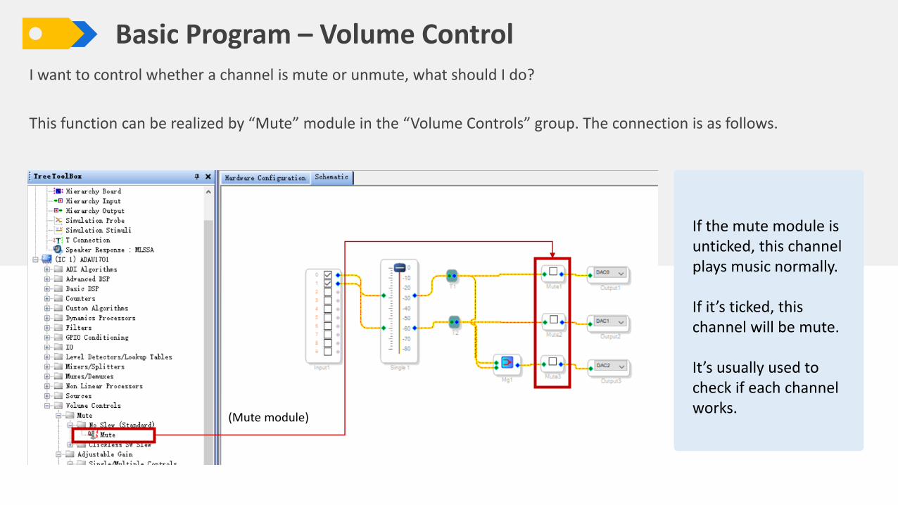
Basic Program – Volume ControlI want to control whether a channel is mute or unmute, what should I do?
This function can be realized by “Mute” module in the “Volume Controls” group. The connection is as follows.
(Mute module)
If the mute module is unticked, this channel plays music normally.
If it’s ticked, this channel will be mute.
It’s usually used to check if each channel works.

This time, let’s add crossover function. We employ “Filters”-“Crossover”-“Double Precision”-“2 -Way”-“Crossover” module
here. You can try other modules by yourself.
Signal Flow: Input left and right channel signal, go through volume control, each channel is split into high frequency and
low frequency. The high is transmitted to stereo output while the low is mixed and transferred to subwoofer output.
(2-way crossover)
Basic Program – Crossover

If crossover module doesn’t have enough the
connection points, you can select the module and
right click, then choose “Add Algorithm”.
(Add connection point)
Click the curve icon of the crossover module, you can
see detailed settings. You can adjust cut-off frequency,
gain, filter type and polarity.
Basic Program – Crossover

Now, we want to add EQ based on finished program, through which we can adjust gain of each frequency to achieve
desired effects. Here we use “Filters”-“Second Order”-“Single Precision”-“2ch”-“Medium Size Eq” module.
(EQ)
Basic Program – EQ

( EQ)
There is only one frequency band of the
module. We can right click with it selected
and choose how many bands you want.
Each center frequency and gain are
adjustable. Here is just for example.
Basic Program – EQ
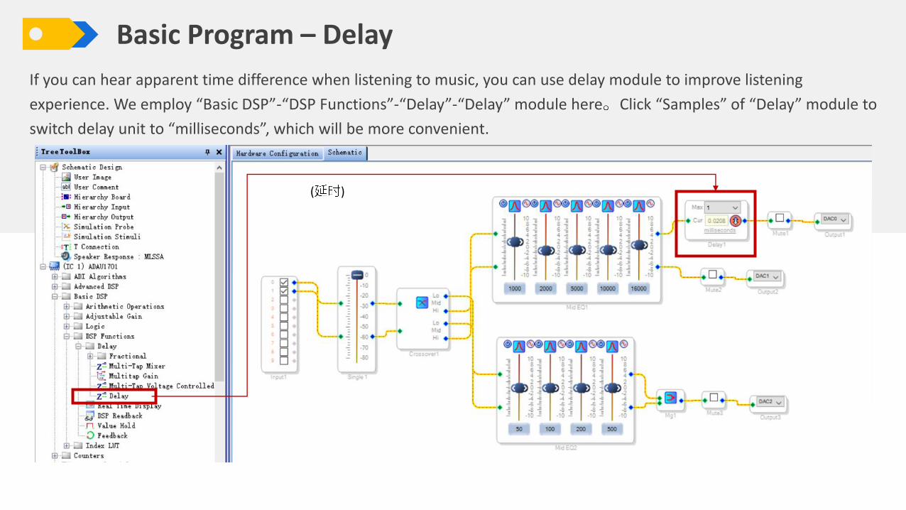
If you can hear apparent time difference when listening to music, you can use delay module to improve listening
experience. We employ “Basic DSP”-“DSP Functions”-“Delay”-“Delay” module here Click “Samples” of “Delay” module to
switch delay unit to “milliseconds”, which will be more convenient.
( )
Basic Program – Delay

We may connect speakers reversely by accident and sometimes we don’t want to reconnect. Then, we can use signal
invert module. We use “Basic DSP”-“Logic”-“Invert”-“Signal Invert” module. Signal will be inverted after ticked.
( )
Basic Program – Signal Invert

Many customers want bass enhancement. We can get this function through “ADI Algorithms”-“Dynamic Bass” module.
You can set the parameters according to the requirements of your audio project.
(Bass Enhancement)
Basic Program – Bass Enhancement
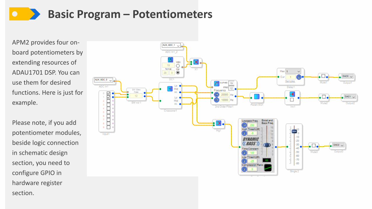
APM2 provides four on-
board potentiometers by
extending resources of
ADAU1701 DSP. You can
use them for desired
functions. Here is just for
example.
Please note, if you add
potentiometer modules,
beside logic connection
in schematic design
section, you need to
configure GPIO in
hardware register
section.
Basic Program – Potentiometers

The potentiometers need to read hardware parameters then transmit to related modules for signal processing. Therefore, we need to adopt modules with control parameters.
Employ gain control module with control
parameters, drag “Auxiliary ADC Input”
module, and complete logic connection
This potentiometer works as high-pass filter of stereo.
The filter module divides 10k-20kHz frequency into 19 curves. The
potentiometer reads hardware voltage and multiply with the value of
DC input Block to convert into frequency signal, which is transferred
to filter to choose corresponding curve.
Basic Program – Potentiometers

After schematic is done, we need to set GPIO in hardware register section. Otherwise, the potentiometers won’t work normally.
Find the GPIO and choose the corresponding ADC in the drop-down menu.
Basic Program – Potentiometers

How to run finished programs offline? We must write them into E2Prom.
If it shows “Design Mode” at the bottom right corner, you need to click “Link Compile Download”. When it shows “Active:
Downloaded”, we can move on to next step.
Basic Program – Program Writing

Click “Hardware Configuration”
Select “ADAU1701” module and
then right click
Choose “Write Latest Compilation
to E2PROM”, you will see the
right window. Click “OK” and wait
for finish.
Basic Program – Program Writing